EP4283764A1 - Pouch forming method - Google Patents
Pouch forming method Download PDFInfo
- Publication number
- EP4283764A1 EP4283764A1 EP22763620.6A EP22763620A EP4283764A1 EP 4283764 A1 EP4283764 A1 EP 4283764A1 EP 22763620 A EP22763620 A EP 22763620A EP 4283764 A1 EP4283764 A1 EP 4283764A1
- Authority
- EP
- European Patent Office
- Prior art keywords
- pouch
- forming
- sheet
- present
- pouch sheet
- Prior art date
- Legal status (The legal status is an assumption and is not a legal conclusion. Google has not performed a legal analysis and makes no representation as to the accuracy of the status listed.)
- Granted
Links
Images







Classifications
-
- H—ELECTRICITY
- H01—ELECTRIC ELEMENTS
- H01M—PROCESSES OR MEANS, e.g. BATTERIES, FOR THE DIRECT CONVERSION OF CHEMICAL ENERGY INTO ELECTRICAL ENERGY
- H01M50/00—Constructional details or processes of manufacture of the non-active parts of electrochemical cells other than fuel cells, e.g. hybrid cells
- H01M50/10—Primary casings; Jackets or wrappings
- H01M50/102—Primary casings; Jackets or wrappings characterised by their shape or physical structure
- H01M50/105—Pouches or flexible bags
-
- B—PERFORMING OPERATIONS; TRANSPORTING
- B29—WORKING OF PLASTICS; WORKING OF SUBSTANCES IN A PLASTIC STATE IN GENERAL
- B29C—SHAPING OR JOINING OF PLASTICS; SHAPING OF MATERIAL IN A PLASTIC STATE, NOT OTHERWISE PROVIDED FOR; AFTER-TREATMENT OF THE SHAPED PRODUCTS, e.g. REPAIRING
- B29C51/00—Shaping by thermoforming, i.e. shaping sheets or sheet like preforms after heating, e.g. shaping sheets in matched moulds or by deep-drawing; Apparatus therefor
- B29C51/10—Forming by pressure difference, e.g. vacuum
-
- B—PERFORMING OPERATIONS; TRANSPORTING
- B32—LAYERED PRODUCTS
- B32B—LAYERED PRODUCTS, i.e. PRODUCTS BUILT-UP OF STRATA OF FLAT OR NON-FLAT, e.g. CELLULAR OR HONEYCOMB, FORM
- B32B15/00—Layered products comprising a layer of metal
- B32B15/04—Layered products comprising a layer of metal comprising metal as the main or only constituent of a layer, which is next to another layer of the same or of a different material
- B32B15/08—Layered products comprising a layer of metal comprising metal as the main or only constituent of a layer, which is next to another layer of the same or of a different material of synthetic resin
-
- B—PERFORMING OPERATIONS; TRANSPORTING
- B32—LAYERED PRODUCTS
- B32B—LAYERED PRODUCTS, i.e. PRODUCTS BUILT-UP OF STRATA OF FLAT OR NON-FLAT, e.g. CELLULAR OR HONEYCOMB, FORM
- B32B15/00—Layered products comprising a layer of metal
- B32B15/04—Layered products comprising a layer of metal comprising metal as the main or only constituent of a layer, which is next to another layer of the same or of a different material
- B32B15/08—Layered products comprising a layer of metal comprising metal as the main or only constituent of a layer, which is next to another layer of the same or of a different material of synthetic resin
- B32B15/085—Layered products comprising a layer of metal comprising metal as the main or only constituent of a layer, which is next to another layer of the same or of a different material of synthetic resin comprising polyolefins
-
- B—PERFORMING OPERATIONS; TRANSPORTING
- B32—LAYERED PRODUCTS
- B32B—LAYERED PRODUCTS, i.e. PRODUCTS BUILT-UP OF STRATA OF FLAT OR NON-FLAT, e.g. CELLULAR OR HONEYCOMB, FORM
- B32B15/00—Layered products comprising a layer of metal
- B32B15/04—Layered products comprising a layer of metal comprising metal as the main or only constituent of a layer, which is next to another layer of the same or of a different material
- B32B15/08—Layered products comprising a layer of metal comprising metal as the main or only constituent of a layer, which is next to another layer of the same or of a different material of synthetic resin
- B32B15/088—Layered products comprising a layer of metal comprising metal as the main or only constituent of a layer, which is next to another layer of the same or of a different material of synthetic resin comprising polyamides
-
- B—PERFORMING OPERATIONS; TRANSPORTING
- B32—LAYERED PRODUCTS
- B32B—LAYERED PRODUCTS, i.e. PRODUCTS BUILT-UP OF STRATA OF FLAT OR NON-FLAT, e.g. CELLULAR OR HONEYCOMB, FORM
- B32B15/00—Layered products comprising a layer of metal
- B32B15/20—Layered products comprising a layer of metal comprising aluminium or copper
-
- B—PERFORMING OPERATIONS; TRANSPORTING
- B32—LAYERED PRODUCTS
- B32B—LAYERED PRODUCTS, i.e. PRODUCTS BUILT-UP OF STRATA OF FLAT OR NON-FLAT, e.g. CELLULAR OR HONEYCOMB, FORM
- B32B27/00—Layered products comprising a layer of synthetic resin
- B32B27/06—Layered products comprising a layer of synthetic resin as the main or only constituent of a layer, which is next to another layer of the same or of a different material
- B32B27/08—Layered products comprising a layer of synthetic resin as the main or only constituent of a layer, which is next to another layer of the same or of a different material of synthetic resin
-
- B—PERFORMING OPERATIONS; TRANSPORTING
- B32—LAYERED PRODUCTS
- B32B—LAYERED PRODUCTS, i.e. PRODUCTS BUILT-UP OF STRATA OF FLAT OR NON-FLAT, e.g. CELLULAR OR HONEYCOMB, FORM
- B32B27/00—Layered products comprising a layer of synthetic resin
- B32B27/32—Layered products comprising a layer of synthetic resin comprising polyolefins
-
- B—PERFORMING OPERATIONS; TRANSPORTING
- B32—LAYERED PRODUCTS
- B32B—LAYERED PRODUCTS, i.e. PRODUCTS BUILT-UP OF STRATA OF FLAT OR NON-FLAT, e.g. CELLULAR OR HONEYCOMB, FORM
- B32B27/00—Layered products comprising a layer of synthetic resin
- B32B27/34—Layered products comprising a layer of synthetic resin comprising polyamides
-
- B—PERFORMING OPERATIONS; TRANSPORTING
- B32—LAYERED PRODUCTS
- B32B—LAYERED PRODUCTS, i.e. PRODUCTS BUILT-UP OF STRATA OF FLAT OR NON-FLAT, e.g. CELLULAR OR HONEYCOMB, FORM
- B32B27/00—Layered products comprising a layer of synthetic resin
- B32B27/36—Layered products comprising a layer of synthetic resin comprising polyesters
-
- B—PERFORMING OPERATIONS; TRANSPORTING
- B32—LAYERED PRODUCTS
- B32B—LAYERED PRODUCTS, i.e. PRODUCTS BUILT-UP OF STRATA OF FLAT OR NON-FLAT, e.g. CELLULAR OR HONEYCOMB, FORM
- B32B7/00—Layered products characterised by the relation between layers; Layered products characterised by the relative orientation of features between layers, or by the relative values of a measurable parameter between layers, i.e. products comprising layers having different physical, chemical or physicochemical properties; Layered products characterised by the interconnection of layers
- B32B7/04—Interconnection of layers
- B32B7/12—Interconnection of layers using interposed adhesives or interposed materials with bonding properties
-
- H—ELECTRICITY
- H01—ELECTRIC ELEMENTS
- H01M—PROCESSES OR MEANS, e.g. BATTERIES, FOR THE DIRECT CONVERSION OF CHEMICAL ENERGY INTO ELECTRICAL ENERGY
- H01M50/00—Constructional details or processes of manufacture of the non-active parts of electrochemical cells other than fuel cells, e.g. hybrid cells
- H01M50/10—Primary casings; Jackets or wrappings
- H01M50/116—Primary casings; Jackets or wrappings characterised by the material
- H01M50/117—Inorganic material
- H01M50/119—Metals
-
- H—ELECTRICITY
- H01—ELECTRIC ELEMENTS
- H01M—PROCESSES OR MEANS, e.g. BATTERIES, FOR THE DIRECT CONVERSION OF CHEMICAL ENERGY INTO ELECTRICAL ENERGY
- H01M50/00—Constructional details or processes of manufacture of the non-active parts of electrochemical cells other than fuel cells, e.g. hybrid cells
- H01M50/10—Primary casings; Jackets or wrappings
- H01M50/116—Primary casings; Jackets or wrappings characterised by the material
- H01M50/121—Organic material
-
- H—ELECTRICITY
- H01—ELECTRIC ELEMENTS
- H01M—PROCESSES OR MEANS, e.g. BATTERIES, FOR THE DIRECT CONVERSION OF CHEMICAL ENERGY INTO ELECTRICAL ENERGY
- H01M50/00—Constructional details or processes of manufacture of the non-active parts of electrochemical cells other than fuel cells, e.g. hybrid cells
- H01M50/10—Primary casings; Jackets or wrappings
- H01M50/116—Primary casings; Jackets or wrappings characterised by the material
- H01M50/124—Primary casings; Jackets or wrappings characterised by the material having a layered structure
- H01M50/126—Primary casings; Jackets or wrappings characterised by the material having a layered structure comprising three or more layers
- H01M50/129—Primary casings; Jackets or wrappings characterised by the material having a layered structure comprising three or more layers with two or more layers of only organic material
-
- B—PERFORMING OPERATIONS; TRANSPORTING
- B29—WORKING OF PLASTICS; WORKING OF SUBSTANCES IN A PLASTIC STATE IN GENERAL
- B29C—SHAPING OR JOINING OF PLASTICS; SHAPING OF MATERIAL IN A PLASTIC STATE, NOT OTHERWISE PROVIDED FOR; AFTER-TREATMENT OF THE SHAPED PRODUCTS, e.g. REPAIRING
- B29C51/00—Shaping by thermoforming, i.e. shaping sheets or sheet like preforms after heating, e.g. shaping sheets in matched moulds or by deep-drawing; Apparatus therefor
- B29C51/08—Deep drawing or matched-mould forming, i.e. using mechanical means only
- B29C51/082—Deep drawing or matched-mould forming, i.e. using mechanical means only by shaping between complementary mould parts
-
- B—PERFORMING OPERATIONS; TRANSPORTING
- B29—WORKING OF PLASTICS; WORKING OF SUBSTANCES IN A PLASTIC STATE IN GENERAL
- B29C—SHAPING OR JOINING OF PLASTICS; SHAPING OF MATERIAL IN A PLASTIC STATE, NOT OTHERWISE PROVIDED FOR; AFTER-TREATMENT OF THE SHAPED PRODUCTS, e.g. REPAIRING
- B29C51/00—Shaping by thermoforming, i.e. shaping sheets or sheet like preforms after heating, e.g. shaping sheets in matched moulds or by deep-drawing; Apparatus therefor
- B29C51/14—Shaping by thermoforming, i.e. shaping sheets or sheet like preforms after heating, e.g. shaping sheets in matched moulds or by deep-drawing; Apparatus therefor using multilayered preforms or sheets
-
- B—PERFORMING OPERATIONS; TRANSPORTING
- B29—WORKING OF PLASTICS; WORKING OF SUBSTANCES IN A PLASTIC STATE IN GENERAL
- B29C—SHAPING OR JOINING OF PLASTICS; SHAPING OF MATERIAL IN A PLASTIC STATE, NOT OTHERWISE PROVIDED FOR; AFTER-TREATMENT OF THE SHAPED PRODUCTS, e.g. REPAIRING
- B29C53/00—Shaping by bending, folding, twisting, straightening or flattening; Apparatus therefor
- B29C53/02—Bending or folding
- B29C53/04—Bending or folding of plates or sheets
-
- B—PERFORMING OPERATIONS; TRANSPORTING
- B29—WORKING OF PLASTICS; WORKING OF SUBSTANCES IN A PLASTIC STATE IN GENERAL
- B29K—INDEXING SCHEME ASSOCIATED WITH SUBCLASSES B29B, B29C OR B29D, RELATING TO MOULDING MATERIALS OR TO MATERIALS FOR MOULDS, REINFORCEMENTS, FILLERS OR PREFORMED PARTS, e.g. INSERTS
- B29K2023/00—Use of polyalkenes or derivatives thereof as moulding material
- B29K2023/10—Polymers of propylene
- B29K2023/12—PP, i.e. polypropylene
-
- B—PERFORMING OPERATIONS; TRANSPORTING
- B29—WORKING OF PLASTICS; WORKING OF SUBSTANCES IN A PLASTIC STATE IN GENERAL
- B29K—INDEXING SCHEME ASSOCIATED WITH SUBCLASSES B29B, B29C OR B29D, RELATING TO MOULDING MATERIALS OR TO MATERIALS FOR MOULDS, REINFORCEMENTS, FILLERS OR PREFORMED PARTS, e.g. INSERTS
- B29K2067/00—Use of polyesters or derivatives thereof, as moulding material
- B29K2067/003—PET, i.e. poylethylene terephthalate
-
- B—PERFORMING OPERATIONS; TRANSPORTING
- B29—WORKING OF PLASTICS; WORKING OF SUBSTANCES IN A PLASTIC STATE IN GENERAL
- B29K—INDEXING SCHEME ASSOCIATED WITH SUBCLASSES B29B, B29C OR B29D, RELATING TO MOULDING MATERIALS OR TO MATERIALS FOR MOULDS, REINFORCEMENTS, FILLERS OR PREFORMED PARTS, e.g. INSERTS
- B29K2077/00—Use of PA, i.e. polyamides, e.g. polyesteramides or derivatives thereof, as moulding material
-
- B—PERFORMING OPERATIONS; TRANSPORTING
- B29—WORKING OF PLASTICS; WORKING OF SUBSTANCES IN A PLASTIC STATE IN GENERAL
- B29L—INDEXING SCHEME ASSOCIATED WITH SUBCLASS B29C, RELATING TO PARTICULAR ARTICLES
- B29L2009/00—Layered products
- B29L2009/003—Layered products comprising a metal layer
-
- B—PERFORMING OPERATIONS; TRANSPORTING
- B29—WORKING OF PLASTICS; WORKING OF SUBSTANCES IN A PLASTIC STATE IN GENERAL
- B29L—INDEXING SCHEME ASSOCIATED WITH SUBCLASS B29C, RELATING TO PARTICULAR ARTICLES
- B29L2031/00—Other particular articles
- B29L2031/712—Containers; Packaging elements or accessories, Packages
- B29L2031/7146—Battery-cases
-
- B—PERFORMING OPERATIONS; TRANSPORTING
- B32—LAYERED PRODUCTS
- B32B—LAYERED PRODUCTS, i.e. PRODUCTS BUILT-UP OF STRATA OF FLAT OR NON-FLAT, e.g. CELLULAR OR HONEYCOMB, FORM
- B32B2439/00—Containers; Receptacles
- B32B2439/02—Open containers
-
- B—PERFORMING OPERATIONS; TRANSPORTING
- B32—LAYERED PRODUCTS
- B32B—LAYERED PRODUCTS, i.e. PRODUCTS BUILT-UP OF STRATA OF FLAT OR NON-FLAT, e.g. CELLULAR OR HONEYCOMB, FORM
- B32B2457/00—Electrical equipment
- B32B2457/10—Batteries
-
- Y—GENERAL TAGGING OF NEW TECHNOLOGICAL DEVELOPMENTS; GENERAL TAGGING OF CROSS-SECTIONAL TECHNOLOGIES SPANNING OVER SEVERAL SECTIONS OF THE IPC; TECHNICAL SUBJECTS COVERED BY FORMER USPC CROSS-REFERENCE ART COLLECTIONS [XRACs] AND DIGESTS
- Y02—TECHNOLOGIES OR APPLICATIONS FOR MITIGATION OR ADAPTATION AGAINST CLIMATE CHANGE
- Y02E—REDUCTION OF GREENHOUSE GAS [GHG] EMISSIONS, RELATED TO ENERGY GENERATION, TRANSMISSION OR DISTRIBUTION
- Y02E60/00—Enabling technologies; Technologies with a potential or indirect contribution to GHG emissions mitigation
- Y02E60/10—Energy storage using batteries
Definitions
- the present invention relates to a method for forming a pouch.
- Secondary batteries are rechargeable unlike primarily batteries, and also, the possibility of compact size and high capacity is high. Thus, recently, many studies on secondary batteries are being carried out. As technology development and demands for mobile devices increase, the demands for secondary batteries as energy sources are rapidly increasing.
- Rechargeable batteries are classified into coin type batteries, cylindrical type batteries, prismatic type batteries, and pouch type batteries according to a shape of a battery case.
- an electrode assembly mounted in a battery case is a chargeable and dischargeable power generating device having a structure in which an electrode and a separator are stacked.
- the electrode assembly may be approximately classified into a jelly roll type electrode assembly in which a separator is interposed between a positive electrode and a negative electrode, each of which is provided as the form of a sheet coated with an active material, and then, the positive electrode, the separator, and the negative electrode are wound, a stacked type electrode assembly in which a plurality of positive and negative electrodes with a separator therebetween are sequentially stacked, and a stack/folding type electrode assembly in which stacked type unit cells are wound together with a separation film having a long length.
- the pouch-type battery in which a stack/folding type electrode assembly is built in a pouch-type battery case provided as an aluminum lamination sheet is attracting much attention due to its low manufacturing cost, small weight, easy shape deformation, and the like, and thus, its usage is gradually increasing.
- One aspect of the present invention is to provide a method for forming a pouch, which is capable of preventing or remarkably reducing an occurrence of curls in a process of forming an accommodation part that accommodates an electrode assembly in a pouch sheet.
- a method for forming a pouch according to the present invention may comprise: a curling process of bending a pouch sheet in a round shape; a seating process of seating the bent pouch sheet on a lower mold, in which a molding groove is formed; and a forming process of pressing the pouch sheet by using a punch mold to form an accommodation part, in which an electrode assembly is accommodated, in the pouch sheet.
- a pouch according to an embodiment of the present invention may be manufactured through the method for forming the pouch according to an embodiment of the present invention.
- a secondary battery according to an embodiment of the present invention may comprise the pouch manufactured through the method for forming the pouch according to an embodiment of the present invention.
- the accommodation groove accommodating the electrode assembly is formed in the pouch sheet after bending the pouch sheet in the round shape, the occurrence of the curls in the pouch may be significantly reduced or prevented.
- FIG. 1 is a perspective view illustrating a curling process in a method for forming a pouch according to an embodiment of the present invention
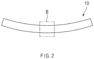
- FIG. 2 is a cross-sectional view taken along line A-A' of FIG. 1
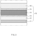
- FIG. 3 is an enlarged cross-sectional view of an area B in FIG. 2 .
- FIG. 4 is a cross-sectional view illustrating a seating process in the method for forming the pouch according to an embodiment of the present invention
- FIG. 5 is a cross-sectional view illustrating a state before pressing a pouch sheet in a forming process in the method for forming the pouch according to an embodiment of the present invention
- FIG. 6 is a cross-sectional view illustrating a state of pressing the pouch sheet in the forming process in the method for forming the pouch according to an embodiment of the present invention.
- a method for forming a pouch may comprise a curling process of bending a pouch sheet 10, a seating process of seating the bent pouch sheet 10 on a lower mold 110, and a forming process of forming an accommodation part 10a in the pouch sheet 10 by using a punch mold 120.
- the pouch sheet 10 in the curling process, may be bent in a round shape.
- the pouch sheet 10 in the curling process, may be bent to be convex downward.
- the pouch sheet 10 in the curling process, may be bent in an arc shape. That is, in the curling process, when the pouch sheet 10 is seated on a lower mold 110, the pouch sheet 10 may be bent to form a convex curvature in a direction of the lower mold 110.
- a degree of crystallinity may be changed by controlling a cooling temperature to bend the pouch sheet 10.
- the pouch sheet 10 may have, for example, a PP layer 16 provided thereon.
- the pouch sheet 10 may be bent by applying tension to the PP layer.
- the pouch sheet 10 may have a structure, in which a PET layer 11, a nylon layer 12, an aluminum layer 14, and the PP layer 16 are stacked upward from a lower side.
- the pouch sheet 10 may further comprise, for example, adhesion layers 13 and 15 on both surfaces of the aluminum layer 14 to firmly adhere between the nylon layer 12, the PET layer 11, and the aluminum layer 14.
- a cooling temperature may be controlled to change the degree of crystallinity of the PP layer 16, thereby applying tension to the PP layer 16. That is, in the curling process, after the PP layer 16 is extruded and attached to the aluminum layer 14, the PP layer 16 is cooled so that the tension is applied to the PP layer, and thus, the pouch sheet 10 may be bent.
- an inner layer of the pouch may be formed when the electrode assembly is accommodated.
- the PP layer 16 may be made of a polypropylene (PP) material, and the nylon layer 12 may be made of a nylon material.
- the aluminum layer 14 may be provided as a sheet made of an aluminum (Al) material, and the PET layer 11 may be made of a polyethylene terephthalate material.
- the bent pouch sheet 10 may be seated on the lower mold 110 in which a molding groove 113 is formed.
- the pouch sheet 10 may be seated so that the convex portion of the pouch sheet 10 faces the molding groove 113 of the lower mold 110.
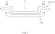
- FIG. 7 is a cross-sectional view illustrating a state in which a punch mold is separated to form a pouch 10' after pressing the pouch sheet in the forming process in the method for forming the pouch according to an embodiment of the present invention.
- the pouch sheet 10 may be pressed through the punch mold 120 to form the accommodation part 10a in which the electrode assembly is accommodated in the pouch sheet 10.
- the pouch sheet 10 may be pressed from an upper side of the pouch sheet 10 in a direction of the lower mold 110 by using punch mold 120 to form the accommodation part 10a corresponding to the molding groove 113 of the lower mold 110, thereby manufacturing the pouch.
- the pouch sheet 10 may be pressed in the direction of the molding groove 113 of the lower mold 110 through the punch mold 120 to significantly prevent or reduce an occurrence of curls in the pouch.
- FIG. 8 is a cross-sectional view illustrating a vacuum adsorption process in a forming process in a method for forming a pouch according to another embodiment of the present invention
- FIG. 9 is a cross-sectional view illustrating a state in which a punch mold is separated after pressing a pouch sheet in the forming process in the method for forming the pouch according to another embodiment of the present invention.
- a method for forming a pouch according to an embodiment of the present invention may comprise a curling process of bending a pouch sheet 10, a seating process of seating the bent pouch sheet 10 on a lower mold 210, and a forming process of forming an accommodation part 10a in the pouch sheet 10 by using a punch mold 120.
- the forming process may comprise a vacuum adsorption process of vacuum-suctioning the pouch sheet 10.
- the method for forming the pouch according to another embodiment of the present invention is different from the method for forming the pouch according to the foregoing embodiment of the present invention in that the vacuum adsorption process is performed in the forming process.
- contents of this embodiment which are duplicated with those according to the foregoing embodiment, will be omitted or briefly described, and also, differences therebetween will be mainly described.
- a pouch sheet 10 may be pressed through a punch mold 120 to form an accommodation part 10a in which an electrode assembly is accommodated in a pouch sheet 10.
- the pouch sheet 10 may be pressed from an upper side of the pouch sheet 10 in a direction of a lower mold 210 by using punch mold 120 to form the accommodation part 10a corresponding to a molding groove 213 of the lower mold 210.
- the forming process may comprise a vacuum adsorption process of vacuum-suctioning the pouch sheet 10.
- the pouch sheet 10 in the vacuum adsorption process, in the forming process, when the pouch sheet 10 is pressed, the pouch sheet 10 may be vacuum-adsorbed through vacuum holes 211 and 212 formed in the lower mold 210.
- the pouch according to an embodiment of the present invention may be manufactured through the method for forming the pouch according to the foregoing embodiment of the present invention or the method for forming the pouch according to the foregoing another embodiment of the present invention.
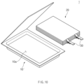
- FIG. 10 is an exploded perspective view illustrating an example of a secondary battery comprising the pouch manufactured in the method for forming the pouch according to an embodiment of the present invention.
- a secondary battery 1 may include a pouch 10' manufactured through the method for forming the pouch according to the foregoing embodiment of the present invention or the method for forming the pouch according to the foregoing another embodiment of the present invention.
- the secondary battery 1 may comprise a pouch 10' and an electrode assembly 20 accommodated in an accommodation part 10a of the pouch 10'.
- an electrode lead 30 may be provided at one side or each of both sides of the electrode assembly 20.
- the electrode lead 30 may be disposed in one direction of the electrode assembly 20 in FIG. 10
- the electrode lead 30 may also be disposed on each of both the sides of the electrode assembly 20.
- FIG. 11 is an image showing a pouch manufactured in a method for forming a pouch according to a related art
- FIG. 12 is an image showing a pouch manufactured in a method for forming a pouch according to an embodiment of the present invention.
- FIG. 11 is an image showing a pouch manufactured through a method for forming a pouch according to the related art, in which a forming process is performed in a flat shape without bending a pouch sheet
- FIG. 12 is an image showing a pouch manufactured through a method for forming a pouch according to an embodiment of the present invention, in which a forming process is performed after a pouch sheet is bent to be rounded in a direction of a molding groove of a lower mold.
- the amount of curling in the pouch manufactured through the method for forming the pouch according to an embodiment of the present invention has a mean value of 25 mm at the upper left position and a mean value of 5.75 mm at the lower right position.
- the amount of curling in the pouch manufactured through the method for forming the pouch according to the related art has a mean value of 42.5 mm at the upper left position and a mean value of 12.75 mm at the lower right position, which are indicated as significantly increasing values.
- the forming process is performed after the pouch sheet is bent to be rounded in the direction of the molding groove of the lower mold to significantly reduce the amount of curling.
Landscapes
- Chemical & Material Sciences (AREA)
- Chemical Kinetics & Catalysis (AREA)
- Electrochemistry (AREA)
- General Chemical & Material Sciences (AREA)
- Engineering & Computer Science (AREA)
- Mechanical Engineering (AREA)
- Inorganic Chemistry (AREA)
- Sealing Battery Cases Or Jackets (AREA)
- Secondary Cells (AREA)
- Making Paper Articles (AREA)
Abstract
Description
- The present application claims the benefit of the priority of
Korean Patent Application No. 10-2021-0029069, filed on March 04, 2021 - The present invention relates to a method for forming a pouch.
- Secondary batteries are rechargeable unlike primarily batteries, and also, the possibility of compact size and high capacity is high. Thus, recently, many studies on secondary batteries are being carried out. As technology development and demands for mobile devices increase, the demands for secondary batteries as energy sources are rapidly increasing.
- Rechargeable batteries are classified into coin type batteries, cylindrical type batteries, prismatic type batteries, and pouch type batteries according to a shape of a battery case. In such a secondary battery, an electrode assembly mounted in a battery case is a chargeable and dischargeable power generating device having a structure in which an electrode and a separator are stacked.
- The electrode assembly may be approximately classified into a jelly roll type electrode assembly in which a separator is interposed between a positive electrode and a negative electrode, each of which is provided as the form of a sheet coated with an active material, and then, the positive electrode, the separator, and the negative electrode are wound, a stacked type electrode assembly in which a plurality of positive and negative electrodes with a separator therebetween are sequentially stacked, and a stack/folding type electrode assembly in which stacked type unit cells are wound together with a separation film having a long length.
- Recently, the pouch-type battery in which a stack/folding type electrode assembly is built in a pouch-type battery case provided as an aluminum lamination sheet is attracting much attention due to its low manufacturing cost, small weight, easy shape deformation, and the like, and thus, its usage is gradually increasing.
- However, there is a problem in that a process of forming an accommodation part in a pouch sheet that accommodates an electrode assembly so as to manufacture a secondary battery is performed to cause curls such as being wound in a circular shape due to a difference in elongation rate between layers in a pouch constituted by the plurality of layers, thereby causing an interference between assembly mechanisms. Also, vacuum adsorption is not performed during the transferring, resulting in a problem that an operation of the equipment is stopped. In addition, there is a problem in that costs for remodeling the equipment to prevent the curls from occurring increase, and in particular, the remodeling of the equipment is not easy in a high-speed production line.
- One aspect of the present invention is to provide a method for forming a pouch, which is capable of preventing or remarkably reducing an occurrence of curls in a process of forming an accommodation part that accommodates an electrode assembly in a pouch sheet.
- A method for forming a pouch according to the present invention may comprise: a curling process of bending a pouch sheet in a round shape; a seating process of seating the bent pouch sheet on a lower mold, in which a molding groove is formed; and a forming process of pressing the pouch sheet by using a punch mold to form an accommodation part, in which an electrode assembly is accommodated, in the pouch sheet.
- A pouch according to an embodiment of the present invention may be manufactured through the method for forming the pouch according to an embodiment of the present invention.
- A secondary battery according to an embodiment of the present invention may comprise the pouch manufactured through the method for forming the pouch according to an embodiment of the present invention.
- According to the present invention, since the accommodation groove accommodating the electrode assembly is formed in the pouch sheet after bending the pouch sheet in the round shape, the occurrence of the curls in the pouch may be significantly reduced or prevented.
-
-
FIG. 1 is a perspective view illustrating a curling process in a method for forming a pouch according to an embodiment of the present invention. -
FIG. 2 is a cross-sectional view taken along line A-A' ofFIG. 1 . -
FIG. 3 is an enlarged cross-sectional view of an area B inFIG. 2 . -
FIG. 4 is a cross-sectional view illustrating a seating process in the method for forming the pouch according to an embodiment of the present invention. -
FIG. 5 is a cross-sectional view illustrating a state before pressing a pouch sheet in a forming process in the method for forming the pouch according to an embodiment of the present invention. -
FIG. 6 is a cross-sectional view illustrating a state of pressing the pouch sheet in the forming process in the method for forming the pouch according to an embodiment of the present invention. -
FIG. 7 is a cross-sectional view illustrating a state in which a punch mold is separated to form a pouch after pressing the pouch sheet in the forming process in the method for forming the pouch according to an embodiment of the present invention. -
FIG. 8 is a cross-sectional view illustrating a vacuum adsorption process in a forming process in a method for forming a pouch according to another embodiment of the present invention. -
FIG. 9 is a cross-sectional view illustrating a state in which a punch mold is separated after pressing a pouch sheet in the forming process in the method for forming the pouch according to another embodiment of the present invention. -
FIG. 10 is an exploded perspective view illustrating an example of a secondary battery comprising the pouch manufactured in the method for forming the pouch according to an embodiment of the present invention. -
FIG. 11 is an image showing a pouch manufactured in a method for forming a pouch according to a related art. -
FIG. 12 is an image showing a pouch manufactured in a method for forming a pouch according to an embodiment of the present invention. - The objectives, specific advantages, and novel features of the present invention will become more apparent from the following detailed description taken in conjunction with the accompanying drawings. It should be noted that the reference numerals are added to the components of the drawings in the present specification with the same numerals as possible, even if they are illustrated in other drawings. Also, the present invention may be embodied in different forms and should not be construed as limited to the embodiments set forth herein. In the following description of the present invention, the detailed descriptions of related arts which may unnecessarily obscure the gist of the present invention will be omitted.
-
FIG. 1 is a perspective view illustrating a curling process in a method for forming a pouch according to an embodiment of the present invention,FIG. 2 is a cross-sectional view taken along line A-A' ofFIG. 1 , andFIG. 3 is an enlarged cross-sectional view of an area B inFIG. 2 . - Also,
FIG. 4 is a cross-sectional view illustrating a seating process in the method for forming the pouch according to an embodiment of the present invention,FIG. 5 is a cross-sectional view illustrating a state before pressing a pouch sheet in a forming process in the method for forming the pouch according to an embodiment of the present invention, andFIG. 6 is a cross-sectional view illustrating a state of pressing the pouch sheet in the forming process in the method for forming the pouch according to an embodiment of the present invention. - Referring to
FIGS. 1 to 6 , a method for forming a pouch according to an embodiment of the present invention may comprise a curling process of bending apouch sheet 10, a seating process of seating thebent pouch sheet 10 on alower mold 110, and a forming process of forming anaccommodation part 10a in thepouch sheet 10 by using apunch mold 120. - Hereinafter, the method for forming the pouch according to an embodiment of the present invention will be described in more detail.
- Referring to
FIGS. 1 to 3 , in the curling process, thepouch sheet 10 may be bent in a round shape. Here, in the curling process, thepouch sheet 10 may be bent to be convex downward. Here, in the curling process, thepouch sheet 10 may be bent in an arc shape. That is, in the curling process, when thepouch sheet 10 is seated on alower mold 110, thepouch sheet 10 may be bent to form a convex curvature in a direction of thelower mold 110. - In the curling process, after lamination of the
pouch sheet 10, a degree of crystallinity may be changed by controlling a cooling temperature to bend thepouch sheet 10. - The
pouch sheet 10 may have, for example, aPP layer 16 provided thereon. Here, in the curling process, thepouch sheet 10 may be bent by applying tension to the PP layer. - In addition, referring to
FIGS. 2 and3 , thepouch sheet 10 may have a structure, in which aPET layer 11, anylon layer 12, analuminum layer 14, and thePP layer 16 are stacked upward from a lower side. Here, thepouch sheet 10 may further comprise, for example,adhesion layers aluminum layer 14 to firmly adhere between thenylon layer 12, thePET layer 11, and thealuminum layer 14. - In the curling process, after laminating the
pouch sheet 10 by applying heat and a pressure, a cooling temperature may be controlled to change the degree of crystallinity of thePP layer 16, thereby applying tension to thePP layer 16. That is, in the curling process, after thePP layer 16 is extruded and attached to thealuminum layer 14, thePP layer 16 is cooled so that the tension is applied to the PP layer, and thus, thepouch sheet 10 may be bent. - Here, although the
PP layer 16 is disposed in an upward direction inFIGS. 2 and3 , an inner layer of the pouch may be formed when the electrode assembly is accommodated. - The
PP layer 16 may be made of a polypropylene (PP) material, and thenylon layer 12 may be made of a nylon material. In addition, thealuminum layer 14 may be provided as a sheet made of an aluminum (Al) material, and thePET layer 11 may be made of a polyethylene terephthalate material. - Referring to
FIG. 4 , in the seating process, thebent pouch sheet 10 may be seated on thelower mold 110 in which amolding groove 113 is formed. - In the seating process, the
pouch sheet 10 may be seated so that the convex portion of thepouch sheet 10 faces themolding groove 113 of thelower mold 110. -
FIG. 7 is a cross-sectional view illustrating a state in which a punch mold is separated to form a pouch 10' after pressing the pouch sheet in the forming process in the method for forming the pouch according to an embodiment of the present invention. - Referring to
FIGS. 5 to 7 , in the forming process, thepouch sheet 10 may be pressed through thepunch mold 120 to form theaccommodation part 10a in which the electrode assembly is accommodated in thepouch sheet 10. - In the forming process, the
pouch sheet 10 may be pressed from an upper side of thepouch sheet 10 in a direction of thelower mold 110 by usingpunch mold 120 to form theaccommodation part 10a corresponding to themolding groove 113 of thelower mold 110, thereby manufacturing the pouch. - In the method for forming the pouch, which is configured as described above, according to the present invention, after the
pouch sheet 10 is bent to be rounded in the direction of themolding groove 113 of thelower mold 110, thepouch sheet 10 may be pressed in the direction of themolding groove 113 of thelower mold 110 through thepunch mold 120 to significantly prevent or reduce an occurrence of curls in the pouch. - Hereinafter, a method for forming a pouch according to another embodiment of the present invention will be described.
-
FIG. 8 is a cross-sectional view illustrating a vacuum adsorption process in a forming process in a method for forming a pouch according to another embodiment of the present invention, andFIG. 9 is a cross-sectional view illustrating a state in which a punch mold is separated after pressing a pouch sheet in the forming process in the method for forming the pouch according to another embodiment of the present invention. - Referring to
FIGS. 8 to 9 , in a method for forming a pouch according to another embodiment of the present invention, a method for forming a pouch according to an embodiment of the present invention may comprise a curling process of bending apouch sheet 10, a seating process of seating thebent pouch sheet 10 on alower mold 210, and a forming process of forming anaccommodation part 10a in thepouch sheet 10 by using apunch mold 120. Here, the forming process may comprise a vacuum adsorption process of vacuum-suctioning thepouch sheet 10. - The method for forming the pouch according to another embodiment of the present invention is different from the method for forming the pouch according to the foregoing embodiment of the present invention in that the vacuum adsorption process is performed in the forming process. Thus, contents of this embodiment, which are duplicated with those according to the foregoing embodiment, will be omitted or briefly described, and also, differences therebetween will be mainly described.
- In more detail, in the forming process in the method for forming the pouch according to another embodiment of the present invention, a
pouch sheet 10 may be pressed through apunch mold 120 to form anaccommodation part 10a in which an electrode assembly is accommodated in apouch sheet 10. - In the forming process, the
pouch sheet 10 may be pressed from an upper side of thepouch sheet 10 in a direction of alower mold 210 by usingpunch mold 120 to form theaccommodation part 10a corresponding to amolding groove 213 of thelower mold 210. - Here, the forming process may comprise a vacuum adsorption process of vacuum-suctioning the
pouch sheet 10. - Here, in the vacuum adsorption process, in the forming process, when the
pouch sheet 10 is pressed, thepouch sheet 10 may be vacuum-adsorbed throughvacuum holes lower mold 210. - Thus, when the
pouch sheet 10 is pressed through thepunch mold 120, movement of thepouch sheet 10 may be prevented. - The pouch according to an embodiment of the present invention may be manufactured through the method for forming the pouch according to the foregoing embodiment of the present invention or the method for forming the pouch according to the foregoing another embodiment of the present invention.
-
FIG. 10 is an exploded perspective view illustrating an example of a secondary battery comprising the pouch manufactured in the method for forming the pouch according to an embodiment of the present invention. - Referring to
FIG. 10 , asecondary battery 1 according to an embodiment of the present invention may include a pouch 10' manufactured through the method for forming the pouch according to the foregoing embodiment of the present invention or the method for forming the pouch according to the foregoing another embodiment of the present invention. - In more detail, the
secondary battery 1 may comprise a pouch 10' and anelectrode assembly 20 accommodated in anaccommodation part 10a of the pouch 10'. - In addition, in the
secondary battery 1, anelectrode lead 30 may be provided at one side or each of both sides of theelectrode assembly 20. Here, although theelectrode lead 30 may be disposed in one direction of theelectrode assembly 20 inFIG. 10 , theelectrode lead 30 may also be disposed on each of both the sides of theelectrode assembly 20. -
FIG. 11 is an image showing a pouch manufactured in a method for forming a pouch according to a related art, andFIG. 12 is an image showing a pouch manufactured in a method for forming a pouch according to an embodiment of the present invention. - Here,
FIG. 11 is an image showing a pouch manufactured through a method for forming a pouch according to the related art, in which a forming process is performed in a flat shape without bending a pouch sheet, andFIG. 12 is an image showing a pouch manufactured through a method for forming a pouch according to an embodiment of the present invention, in which a forming process is performed after a pouch sheet is bent to be rounded in a direction of a molding groove of a lower mold. - An amount of curling in each of the pouches manufactured according to the present invention and the related art, which are illustrated in
FIGS. 11 and12 , was measured to be shown in Table 1 below. In Table 1,Product 1 and Product 2 in the pouch according to the related art are shown in left and right images ofFIG. 11 , and Product 3 and Product 4 in the pouch according to the present invention are shown in left and right images ofFIG. 12 .[Table 1] Classification Amount of curling (mm) Upper left Lower left Upper right Lower right Pouch of related art Product 1 40 21.5 14 39.5 Product 2 45 23 11.5 41 Pouch of present invention Product 3 26 12 5 27 Product 4 24 9 6.5 22 - As shown in Table 1 above, the amount of curling in the pouch manufactured through the method for forming the pouch according to an embodiment of the present invention has a mean value of 25 mm at the upper left position and a mean value of 5.75 mm at the lower right position. On the other hand, the amount of curling in the pouch manufactured through the method for forming the pouch according to the related art has a mean value of 42.5 mm at the upper left position and a mean value of 12.75 mm at the lower right position, which are indicated as significantly increasing values. Thus, in the pouch manufactured through the method for forming the pouch according to an embodiment of the present invention, it is seen that the forming process is performed after the pouch sheet is bent to be rounded in the direction of the molding groove of the lower mold to significantly reduce the amount of curling.
- While the present invention has been particularly shown and described with reference to the specific embodiments, it is to be understood that the scope of the present invention is not limited to the method for forming the pouch according to the present invention. It will be understood by those of ordinary skill in the art that various changes in form and details may be made therein without departing from the spirit and scope of the present invention.
- Furthermore, the scope of protection of the present invention will be clarified by the appended claims.
-
- 1: Secondary battery
- 10: Pouch sheet
- 10a: Accommodation part
- 20: Electrode assembly
- 30: Electrode lead
- 110, 210: Lower mold
- 113, 213: Molding groove
- 120: Punch mold
- 211, 212: Vacuum hole
Claims (11)
- A method for forming a pouch, the method comprising:a curling process of bending a pouch sheet in a round shape;a seating process of seating the bent pouch sheet on a lower mold, in which a molding groove is formed; anda forming process of pressing the pouch sheet by using a punch mold to form an accommodation part, in which an electrode assembly is accommodated, in the pouch sheet.
- The method for forming a pouch of claim 1, wherein, in the curling process, the pouch sheet is bent to be convex downward.
- The method for forming a pouch of claim 2, wherein, in the curling process, the pouch sheet is bent in an arc shape.
- The method for forming a pouch of claim 2, wherein, in the seating process, the pouch sheet is seated so that a convex portion of the pouch sheet faces the molding groove of the lower mold.
- The method for forming a pouch of claim 4, wherein a polypropylene (PP) layer is provided on the pouch sheet, and
in the curling process, tension is applied to the PP layer to bend the pouch sheet. - The method for forming a pouch of claim 5, wherein, in the curling process, after the pouch sheet comprising a plurality of layers is laminated, the PP layer is cooled to apply the tension to the PP layer.
- The method for forming a pouch of claim 5, wherein the pouch sheet is formed by stacking a PET layer, a nylon layer, an aluminum layer, and the PP layer upward from a lower side.
- The method for forming a pouch of claim 5, wherein, in the forming process, the pouch sheet is pressed from an upper side of the pouch sheet in a direction of the lower mold by using the punch mold to form the accommodation part corresponding to the molding groove of the lower mold.
- The method for forming a pouch of claim 1, wherein the forming process comprises a vacuum adsorption process of vacuum-adsorbing the pouch sheet through a vacuum hole formed in the lower mold when the pouch sheet is pressed.
- A pouch manufactured through the method for forming a pouch of any one of claims 1 to 9.
- A secondary battery comprising the pouch manufactured through the method for forming a pouch of any one of claims 1 to 9.
Applications Claiming Priority (2)
| Application Number | Priority Date | Filing Date | Title |
|---|---|---|---|
| KR1020210029069A KR102790884B1 (en) | 2021-03-04 | 2021-03-04 | Pouch forming method |
| PCT/KR2022/003040 WO2022186639A1 (en) | 2021-03-04 | 2022-03-03 | Pouch forming method |
Publications (3)
| Publication Number | Publication Date |
|---|---|
| EP4283764A1 true EP4283764A1 (en) | 2023-11-29 |
| EP4283764A4 EP4283764A4 (en) | 2025-04-30 |
| EP4283764B1 EP4283764B1 (en) | 2026-04-29 |
Family
ID=83154270
Family Applications (1)
| Application Number | Title | Priority Date | Filing Date |
|---|---|---|---|
| EP22763620.6A Active EP4283764B1 (en) | 2021-03-04 | 2022-03-03 | Pouch forming method |
Country Status (5)
| Country | Link |
|---|---|
| US (1) | US12548825B2 (en) |
| EP (1) | EP4283764B1 (en) |
| KR (1) | KR102790884B1 (en) |
| CN (1) | CN116964834A (en) |
| WO (1) | WO2022186639A1 (en) |
Families Citing this family (2)
| Publication number | Priority date | Publication date | Assignee | Title |
|---|---|---|---|---|
| KR20240087284A (en) | 2022-12-12 | 2024-06-19 | 주식회사 엘지에너지솔루션 | Secondary Battery Pack |
| KR20250145975A (en) * | 2024-03-29 | 2025-10-13 | 주식회사 엘지에너지솔루션 | System and method for producing battery cell packaging material |
Family Cites Families (23)
| Publication number | Priority date | Publication date | Assignee | Title |
|---|---|---|---|---|
| JP2002050326A (en) * | 2000-05-25 | 2002-02-15 | Sumitomo Electric Ind Ltd | Method for drawing film for battery package, method for forming laminate film and battery |
| JP2003187759A (en) | 2001-12-20 | 2003-07-04 | Mitsubishi Chemicals Corp | Secondary battery and method of manufacturing secondary battery |
| CN101193750B (en) | 2005-04-18 | 2011-02-16 | 东洋纺织株式会社 | Film-laminated polyimide film and flexible printed circuit board |
| JP3912615B2 (en) * | 2005-04-19 | 2007-05-09 | 東洋紡績株式会社 | Thin film laminated polyimide film, thin film laminated polyimide film roll and use thereof |
| JP2008216215A (en) | 2007-03-07 | 2008-09-18 | Toyota Motor Corp | Sheet curvature measuring apparatus and sheet curvature measuring method |
| US20120183825A1 (en) | 2011-01-14 | 2012-07-19 | Seung-Hun Lee | Secondary battery and method of manufacturing the same |
| KR101415575B1 (en) | 2011-10-18 | 2014-07-07 | 에스케이이노베이션 주식회사 | Wrapping Method of Jelly roll for Battery Cell of Secondary Battery |
| KR101528001B1 (en) | 2012-06-22 | 2015-06-10 | 주식회사 엘지화학 | Electrode assembly, manufacture thereof, and secondary batteries including same |
| JP2015051525A (en) | 2013-09-05 | 2015-03-19 | 出光ユニテック株式会社 | Biaxially stretched nylon film, laminate film, laminate packaging material, battery, and method for producing biaxially stretched nylon film |
| KR101816946B1 (en) | 2013-10-30 | 2018-01-09 | 주식회사 엘지화학 | Cell case, its manufacturing metallic mold and manufacturing method, battery cell |
| KR102221808B1 (en) | 2014-08-11 | 2021-03-02 | 삼성에스디아이 주식회사 | Secondary battery |
| KR101879911B1 (en) | 2015-03-27 | 2018-07-18 | 주식회사 엘지화학 | Method for Production of Curved-Shaped Battery Cell |
| US20170092912A1 (en) | 2015-09-30 | 2017-03-30 | Sumitomo Chemical Company, Limited | Film production method, battery separator film, nonaqueous electrolyte secondary battery separator, and nonaqueous electrolyte secondary battery |
| KR102150010B1 (en) | 2016-09-21 | 2020-08-31 | 주식회사 엘지화학 | Deep Drawing Apparatus for Laminated Sheet Capable of Adjusting Tension and Method for Deep Drawing Using the Same |
| KR102187172B1 (en) | 2016-12-01 | 2020-12-07 | 주식회사 엘지화학 | Mold apparatus and manufacturing method of curved secondary battery using the same |
| KR20180092174A (en) * | 2017-02-08 | 2018-08-17 | 주식회사 엘지화학 | Apparatus and method for forming pouch of secondary battery secured residual thickness |
| KR102261672B1 (en) | 2017-04-24 | 2021-06-08 | 주식회사 엘지에너지솔루션 | Battery Case Having Anti-Curl Guideline and Apparatus thereor |
| KR102217451B1 (en) | 2017-08-29 | 2021-02-22 | 주식회사 엘지화학 | Rechargeable battery and the manufacturing method, and press block for rechargeable battery |
| KR102531552B1 (en) | 2017-11-23 | 2023-05-12 | 주식회사 엘지에너지솔루션 | device for pressing secondary battery method of manufacturing secondary battery |
| KR102766735B1 (en) * | 2018-02-07 | 2025-02-12 | 다이니폰 인사츠 가부시키가이샤 | Battery packaging material, manufacturing method thereof, and battery |
| KR102137541B1 (en) * | 2018-06-26 | 2020-07-24 | (주)광신하이테크 | Large capacity Battery pouch film forming cutting device and foaming cutting method |
| KR102131739B1 (en) | 2018-11-09 | 2020-07-09 | 주식회사 엘지화학 | Pouch forming method and pouch forming device |
| EP4467624A3 (en) * | 2019-12-27 | 2025-02-19 | Toppan Inc. | Power storage device packaging material and power storage device using the same |
-
2021
- 2021-03-04 KR KR1020210029069A patent/KR102790884B1/en active Active
-
2022
- 2022-03-03 WO PCT/KR2022/003040 patent/WO2022186639A1/en not_active Ceased
- 2022-03-03 EP EP22763620.6A patent/EP4283764B1/en active Active
- 2022-03-03 US US18/279,656 patent/US12548825B2/en active Active
- 2022-03-03 CN CN202280019064.9A patent/CN116964834A/en active Pending
Also Published As
| Publication number | Publication date |
|---|---|
| EP4283764B1 (en) | 2026-04-29 |
| KR102790884B1 (en) | 2025-04-04 |
| US20240297377A1 (en) | 2024-09-05 |
| KR20220125096A (en) | 2022-09-14 |
| EP4283764A4 (en) | 2025-04-30 |
| US12548825B2 (en) | 2026-02-10 |
| WO2022186639A1 (en) | 2022-09-09 |
| CN116964834A (en) | 2023-10-27 |
Similar Documents
| Publication | Publication Date | Title |
|---|---|---|
| US11799122B2 (en) | Pouch for a secondary battery including a bridge and accommodation grooves | |
| EP3518306B1 (en) | Secondary battery and manufacturing method thereof | |
| JP2019179764A (en) | Apparatus and method for manufacturing electrode assembly, and electrode assembly manufactured using the same | |
| KR101553542B1 (en) | Cell stacking method for Secondary Battery and cell stack for using the same | |
| US20220246974A1 (en) | Method for manufacturing electrode assembly, electrode assembly manufactured therethrough, and secondary battery | |
| KR101291063B1 (en) | Stacking system and method for Secondary Battery | |
| US20200153025A1 (en) | Pouch forming method and pouch forming device | |
| US11799173B2 (en) | Secondary battery and manufacturing method thereof | |
| EP4283764B1 (en) | Pouch forming method | |
| KR20230109917A (en) | Secondary battery manufacturing apparatus and secondary battery manufacturing method | |
| EP4300647A1 (en) | Electrode assembly and battery cell including same | |
| JP2025039726A (en) | Secondary battery manufacturing method and secondary battery | |
| KR102663799B1 (en) | Secondary battery and manufacturing method for the same | |
| CN108370057A (en) | Electrode assembly manufacturing method and electrochemical device using the electrode assembly manufactured by the manufacturing method | |
| US20250286111A1 (en) | Pressing apparatus for secondary batteries, secondary battery manufactured using the same, and method of manufacturing the same | |
| CN116171499B (en) | Secondary battery manufacturing method and secondary battery | |
| JP7693990B2 (en) | Electrode assembly and secondary battery including the same | |
| EP4131589B1 (en) | Secondary battery manufacturing method | |
| US20240055877A1 (en) | Pressurizing channel and secondary battery charging/discharging device comprising same | |
| KR20250072076A (en) | Taping Device for Secondary Battery and Secondary Battery manufactured using the Device | |
| CN117157789A (en) | Electrode assembly and battery cell including the same | |
| KR20250117029A (en) | Secondary battery manufacturing device and manufacturing method | |
| KR20220040361A (en) | Rechargeable battery manufacturing method and rechargeable battery | |
| KR20180008038A (en) | Electrode assembly and the manufacturing method |
Legal Events
| Date | Code | Title | Description |
|---|---|---|---|
| STAA | Information on the status of an ep patent application or granted ep patent |
Free format text: STATUS: THE INTERNATIONAL PUBLICATION HAS BEEN MADE |
|
| PUAI | Public reference made under article 153(3) epc to a published international application that has entered the european phase |
Free format text: ORIGINAL CODE: 0009012 |
|
| STAA | Information on the status of an ep patent application or granted ep patent |
Free format text: STATUS: REQUEST FOR EXAMINATION WAS MADE |
|
| 17P | Request for examination filed |
Effective date: 20230825 |
|
| AK | Designated contracting states |
Kind code of ref document: A1 Designated state(s): AL AT BE BG CH CY CZ DE DK EE ES FI FR GB GR HR HU IE IS IT LI LT LU LV MC MK MT NL NO PL PT RO RS SE SI SK SM TR |
|
| DAV | Request for validation of the european patent (deleted) | ||
| DAX | Request for extension of the european patent (deleted) | ||
| A4 | Supplementary search report drawn up and despatched |
Effective date: 20250328 |
|
| RIC1 | Information provided on ipc code assigned before grant |
Ipc: B32B 15/20 20060101ALI20250324BHEP Ipc: B32B 15/08 20060101ALI20250324BHEP Ipc: H01M 50/129 20210101ALI20250324BHEP Ipc: H01M 50/105 20210101AFI20250324BHEP |
|
| GRAP | Despatch of communication of intention to grant a patent |
Free format text: ORIGINAL CODE: EPIDOSNIGR1 |
|
| STAA | Information on the status of an ep patent application or granted ep patent |
Free format text: STATUS: GRANT OF PATENT IS INTENDED |
|
| INTG | Intention to grant announced |
Effective date: 20251205 |
|
| P01 | Opt-out of the competence of the unified patent court (upc) registered |
Free format text: CASE NUMBER: UPC_APP_0000263_4283764/2026 Effective date: 20260106 |
|
| GRAS | Grant fee paid |
Free format text: ORIGINAL CODE: EPIDOSNIGR3 |
|
| GRAA | (expected) grant |
Free format text: ORIGINAL CODE: 0009210 |
|
| STAA | Information on the status of an ep patent application or granted ep patent |
Free format text: STATUS: THE PATENT HAS BEEN GRANTED |
|
| AK | Designated contracting states |
Kind code of ref document: B1 Designated state(s): AL AT BE BG CH CY CZ DE DK EE ES FI FR GB GR HR HU IE IS IT LI LT LU LV MC MK MT NL NO PL PT RO RS SE SI SK SM TR |
|
| REG | Reference to a national code |
Ref country code: CH Ref legal event code: F10 Free format text: ST27 STATUS EVENT CODE: U-0-0-F10-F00 (AS PROVIDED BY THE NATIONAL OFFICE) Effective date: 20260429 Ref country code: GB Ref legal event code: FG4D |