EP4283763A1 - Battery temperature regulation system - Google Patents
Battery temperature regulation system Download PDFInfo
- Publication number
- EP4283763A1 EP4283763A1 EP23173477.3A EP23173477A EP4283763A1 EP 4283763 A1 EP4283763 A1 EP 4283763A1 EP 23173477 A EP23173477 A EP 23173477A EP 4283763 A1 EP4283763 A1 EP 4283763A1
- Authority
- EP
- European Patent Office
- Prior art keywords
- battery
- temperature
- mode
- thermoelectric device
- polarity
- Prior art date
- Legal status (The legal status is an assumption and is not a legal conclusion. Google has not performed a legal analysis and makes no representation as to the accuracy of the status listed.)
- Pending
Links
- 238000001816 cooling Methods 0.000 claims abstract description 25
- 238000010438 heat treatment Methods 0.000 claims abstract description 25
- 238000000034 method Methods 0.000 claims abstract description 24
- 238000007600 charging Methods 0.000 claims description 15
- 238000012544 monitoring process Methods 0.000 claims description 3
- 230000001105 regulatory effect Effects 0.000 claims description 3
- 238000010586 diagram Methods 0.000 description 11
- 239000004065 semiconductor Substances 0.000 description 5
- 230000001276 controlling effect Effects 0.000 description 4
- 239000000463 material Substances 0.000 description 4
- 238000004364 calculation method Methods 0.000 description 3
- OKTJSMMVPCPJKN-UHFFFAOYSA-N Carbon Chemical compound [C] OKTJSMMVPCPJKN-UHFFFAOYSA-N 0.000 description 2
- 238000007726 management method Methods 0.000 description 2
- 238000011144 upstream manufacturing Methods 0.000 description 2
- WHXSMMKQMYFTQS-UHFFFAOYSA-N Lithium Chemical compound [Li] WHXSMMKQMYFTQS-UHFFFAOYSA-N 0.000 description 1
- 241000270295 Serpentes Species 0.000 description 1
- 230000032683 aging Effects 0.000 description 1
- MRPWWVMHWSDJEH-UHFFFAOYSA-N antimony telluride Chemical compound [SbH3+3].[SbH3+3].[TeH2-2].[TeH2-2].[TeH2-2] MRPWWVMHWSDJEH-UHFFFAOYSA-N 0.000 description 1
- 229910052797 bismuth Inorganic materials 0.000 description 1
- JCXGWMGPZLAOME-UHFFFAOYSA-N bismuth atom Chemical compound [Bi] JCXGWMGPZLAOME-UHFFFAOYSA-N 0.000 description 1
- 239000002041 carbon nanotube Substances 0.000 description 1
- 229910021393 carbon nanotube Inorganic materials 0.000 description 1
- 230000032677 cell aging Effects 0.000 description 1
- 239000000919 ceramic Substances 0.000 description 1
- 238000004891 communication Methods 0.000 description 1
- 238000004590 computer program Methods 0.000 description 1
- 238000010281 constant-current constant-voltage charging Methods 0.000 description 1
- 238000010276 construction Methods 0.000 description 1
- 230000007423 decrease Effects 0.000 description 1
- 238000007599 discharging Methods 0.000 description 1
- 239000003792 electrolyte Substances 0.000 description 1
- 238000005562 fading Methods 0.000 description 1
- 230000006870 function Effects 0.000 description 1
- 229910002804 graphite Inorganic materials 0.000 description 1
- 239000010439 graphite Substances 0.000 description 1
- 150000002500 ions Chemical class 0.000 description 1
- 239000007788 liquid Substances 0.000 description 1
- 229910052744 lithium Inorganic materials 0.000 description 1
- 230000010287 polarization Effects 0.000 description 1
- XSOKHXFFCGXDJZ-UHFFFAOYSA-N telluride(2-) Chemical compound [Te-2] XSOKHXFFCGXDJZ-UHFFFAOYSA-N 0.000 description 1
Images



Classifications
-
- H—ELECTRICITY
- H01—ELECTRIC ELEMENTS
- H01M—PROCESSES OR MEANS, e.g. BATTERIES, FOR THE DIRECT CONVERSION OF CHEMICAL ENERGY INTO ELECTRICAL ENERGY
- H01M10/00—Secondary cells; Manufacture thereof
- H01M10/60—Heating or cooling; Temperature control
- H01M10/61—Types of temperature control
- H01M10/613—Cooling or keeping cold
-
- H—ELECTRICITY
- H01—ELECTRIC ELEMENTS
- H01M—PROCESSES OR MEANS, e.g. BATTERIES, FOR THE DIRECT CONVERSION OF CHEMICAL ENERGY INTO ELECTRICAL ENERGY
- H01M10/00—Secondary cells; Manufacture thereof
- H01M10/42—Methods or arrangements for servicing or maintenance of secondary cells or secondary half-cells
- H01M10/425—Structural combination with electronic components, e.g. electronic circuits integrated to the outside of the casing
-
- H—ELECTRICITY
- H01—ELECTRIC ELEMENTS
- H01M—PROCESSES OR MEANS, e.g. BATTERIES, FOR THE DIRECT CONVERSION OF CHEMICAL ENERGY INTO ELECTRICAL ENERGY
- H01M10/00—Secondary cells; Manufacture thereof
- H01M10/42—Methods or arrangements for servicing or maintenance of secondary cells or secondary half-cells
- H01M10/48—Accumulators combined with arrangements for measuring, testing or indicating the condition of cells, e.g. the level or density of the electrolyte
- H01M10/486—Accumulators combined with arrangements for measuring, testing or indicating the condition of cells, e.g. the level or density of the electrolyte for measuring temperature
-
- H—ELECTRICITY
- H01—ELECTRIC ELEMENTS
- H01M—PROCESSES OR MEANS, e.g. BATTERIES, FOR THE DIRECT CONVERSION OF CHEMICAL ENERGY INTO ELECTRICAL ENERGY
- H01M10/00—Secondary cells; Manufacture thereof
- H01M10/60—Heating or cooling; Temperature control
- H01M10/61—Types of temperature control
- H01M10/615—Heating or keeping warm
-
- H—ELECTRICITY
- H01—ELECTRIC ELEMENTS
- H01M—PROCESSES OR MEANS, e.g. BATTERIES, FOR THE DIRECT CONVERSION OF CHEMICAL ENERGY INTO ELECTRICAL ENERGY
- H01M10/00—Secondary cells; Manufacture thereof
- H01M10/60—Heating or cooling; Temperature control
- H01M10/63—Control systems
-
- H—ELECTRICITY
- H01—ELECTRIC ELEMENTS
- H01M—PROCESSES OR MEANS, e.g. BATTERIES, FOR THE DIRECT CONVERSION OF CHEMICAL ENERGY INTO ELECTRICAL ENERGY
- H01M10/00—Secondary cells; Manufacture thereof
- H01M10/60—Heating or cooling; Temperature control
- H01M10/65—Means for temperature control structurally associated with the cells
- H01M10/651—Means for temperature control structurally associated with the cells characterised by parameters specified by a numeric value or mathematical formula, e.g. ratios, sizes or concentrations
-
- H—ELECTRICITY
- H01—ELECTRIC ELEMENTS
- H01M—PROCESSES OR MEANS, e.g. BATTERIES, FOR THE DIRECT CONVERSION OF CHEMICAL ENERGY INTO ELECTRICAL ENERGY
- H01M10/00—Secondary cells; Manufacture thereof
- H01M10/60—Heating or cooling; Temperature control
- H01M10/65—Means for temperature control structurally associated with the cells
- H01M10/653—Means for temperature control structurally associated with the cells characterised by electrically insulating or thermally conductive materials
-
- H—ELECTRICITY
- H01—ELECTRIC ELEMENTS
- H01M—PROCESSES OR MEANS, e.g. BATTERIES, FOR THE DIRECT CONVERSION OF CHEMICAL ENERGY INTO ELECTRICAL ENERGY
- H01M10/00—Secondary cells; Manufacture thereof
- H01M10/60—Heating or cooling; Temperature control
- H01M10/65—Means for temperature control structurally associated with the cells
- H01M10/657—Means for temperature control structurally associated with the cells by electric or electromagnetic means
- H01M10/6572—Peltier elements or thermoelectric devices
-
- H—ELECTRICITY
- H01—ELECTRIC ELEMENTS
- H01M—PROCESSES OR MEANS, e.g. BATTERIES, FOR THE DIRECT CONVERSION OF CHEMICAL ENERGY INTO ELECTRICAL ENERGY
- H01M10/00—Secondary cells; Manufacture thereof
- H01M10/60—Heating or cooling; Temperature control
- H01M10/65—Means for temperature control structurally associated with the cells
- H01M10/655—Solid structures for heat exchange or heat conduction
- H01M10/6551—Surfaces specially adapted for heat dissipation or radiation, e.g. fins or coatings
-
- Y—GENERAL TAGGING OF NEW TECHNOLOGICAL DEVELOPMENTS; GENERAL TAGGING OF CROSS-SECTIONAL TECHNOLOGIES SPANNING OVER SEVERAL SECTIONS OF THE IPC; TECHNICAL SUBJECTS COVERED BY FORMER USPC CROSS-REFERENCE ART COLLECTIONS [XRACs] AND DIGESTS
- Y02—TECHNOLOGIES OR APPLICATIONS FOR MITIGATION OR ADAPTATION AGAINST CLIMATE CHANGE
- Y02E—REDUCTION OF GREENHOUSE GAS [GHG] EMISSIONS, RELATED TO ENERGY GENERATION, TRANSMISSION OR DISTRIBUTION
- Y02E60/00—Enabling technologies; Technologies with a potential or indirect contribution to GHG emissions mitigation
- Y02E60/10—Energy storage using batteries
Definitions
- the present disclosure relates generally to the field of managing a battery and, more specifically to operating a battery within a temperature range.
- high temperatures result in faster cell aging and capacity fading that potentially lead to a thermal runaway.
- Low temperatures result in higher voltage drop inside the cell because of a larger equivalent internal resistance and thus lower output power capability.
- Use in low temperatures can result in lower useful capacity and can also limit the rate of charge or discharge due to a reduced mobility of ions and increased viscosity of electrolyte.
- Typical battery thermal management systems are not designed and operated for achieving an optimum capacity and/or an optimum rate of charge and discharge.
- the systems include a thermal management method that cools by liquid or forced air, and heats by use of a heat exchanger and external heating. Issues with these systems is they are often bulky that reduces the contexts in which they can be used. These systems are also limited to contexts that are not sensitive to weight/volume control.
- thermoelectric device configured to attach to the battery and operate in a heating mode to elevate the operating temperature of the battery and in a cooling mode to reduce the operating temperature of the battery.
- Control circuitry is configured to: determine a temperature of the battery; supply an input voltage and a polarity of the thermoelectric device; and adjust the input voltage and the polarity based on a temperature of the battery.
- control circuitry comprises: a power conditioner that supplies the input voltage and the polarity of the thermoelectric device; and a local controller that adjusts the input voltage and the polarity based on the operating temperature of the battery.
- a thermally conductive wrap is configured to contact against individual cells of the battery and conduct heat from the thermoelectric device to the individual cells when operating in the heating mode and conducts the heat from the individual cells to the thermoelectric device when operating in the cooling mode.
- a sensor is configured to sense the temperature of the battery and transmit a corresponding signal to the control circuitry.
- control circuitry comprises a local controller and further comprises a system controller configured to receive a user input and to transmit a temperature setting point to the local controller.
- system controller determines whether the battery should be in one of capacity control mode and rate control mode.
- system controller is further configured to operate in an auto mode that switches between the capacity control mode and the rate control mode based on a load on the battery, and a manual temperature setting mode in which the temperature of the battery is set based on user input.
- control circuitry further comprises: a DC/DC converter; and an H-bridge to adjust a polarity of the input voltage of the thermoelectric device.
- thermoelectric device is configured to act in the heating mode in a first polarity and to act in the cooling mode in a second polarity.
- thermoelectric device that heats the battery when operated in a first polarity and that cools the battery when operated in a second polarity
- control unit comprising control circuitry configured to monitor a temperature of the battery and determine a temperature setting for the battery
- control operation of the thermoelectric device between the first polarity and the second polarity and adjust a voltage supplied to the thermoelectric device to maintain the battery operating within the temperature range.
- control unit comprises: a power conditioner comprising a DC/DC converter and an H-bridge; and a local controller that receives signals from a sensor at the battery to monitor the temperature of the battery.
- thermoelectric device comprises an array of n-type and p-type semiconductor materials that are electrically and thermally connected together and positioned between opposing plates.
- control unit further comprises: a DC/DC converter; and an H-bridge to adjust the polarity of the thermoelectric device.
- a system controller is located remotely from the control unit with the system controller comprising system control circuitry configured to: receive user input; based on the user input, determine when the battery should be in one of capacity control mode and rate control mode.
- a thermally conductive wrap is configured to contact against individual cells of the battery and conduct heat from the thermoelectric device to heat the individual cells when operating in one of the polarities and conduct the heat from the individual cells to the thermoelectric device when operating in a second one of the polarities.
- a power source provides power to the control unit.
- One aspect is directed to a method of regulating a temperature of a battery with the method comprising: determining a temperature range for the battery; monitoring a temperature of the battery; when the temperature is below the temperature range, operating a thermoelectric device thermally connected to the battery in a first polarity and heating the battery; and when the temperature is above the temperature range, operating the thermoelectric device in a second polarity and cooling the battery.
- the method comprises receiving user input and determining the temperature range based on the user input.
- the method comprises determining an operating mode of the battery and determining the temperature range based on the operating mode.
- the method comprises determining the temperature range for the battery based on whether operating in a rate-optimizing charging mode or a capacity-optimizing charging mode.
- FIG. 1 schematically illustrates a system 10 for controlling a temperature of a battery 100.
- a thermoelectric device 20 is positioned to heat and/or cool the battery 100.
- a power conditioner 50 is operatively connected to the thermoelectric device 20.
- the power conditioner 50 regulates an input voltage and a polarity of the input voltage to the thermoelectric device 20.
- a local controller 60 determines a mode for the battery 100 and an operating temperature range. The local control 60 controls the power conditioner 50 to set the polarity and input voltage based on the need to cool or heat the battery 100 to operate within the temperature range.
- thermoelectric device 20 is positioned to heat or cool the battery 100.
- Figure 2A illustrates an example of a thermoelectric device 20 that includes an array 21 of alternating n- and p- type semiconductors that are positioned between opposing plates 22, 23.
- the array 21 of semiconductors are soldered between the plates 22, 23 and are electrically in series and thermally in parallel.
- semiconductor materials include but are not limited to bismuth, telluride, and antimony telluride.
- a voltage is applied across the plates 22, 23 to create an electric current. When current flows through the junctions of the two plates 22, 23, heat is removed at one junction and cooling occurs while heat is deposited at the other junction.
- a heat sink 24 that includes an exposed surface area such as fins can be attached to the outer plate 23 to further facilitate the heat transfer.
- the plates 22, 23 are ceramic.
- FIG. 2A illustrates the thermoelectric device 20 operating in cooling mode to remove heat from the battery 100.
- the plate 22 is positioned in thermal contact with the battery 100. Electric energy is supplied to the plates 22, 23 thus causing heat from the battery 100 to be removed through the contact with the plate 22. The heat is then thermally conducted through the array 21 and to the plate 23 where it is released directly into the environment and/or through the heat sink 24.
- the polarity of the supplied electric energy can be reversed for the thermoelectric device 20 to operate in a heating mode. As illustrated in Figure 2B , the reversed polarity provides for heat to be collected at the plate 23 directly from the environment and/or through the heat sink 24. The heat is transferred through the array 21 and plate 22 to the battery 100.
- Figure 3 illustrates an example of the system 10 connected to a battery 100 to control a temperature of the battery 100.
- the battery 100 includes a series of pouch or prismatic battery cells 101.
- the battery includes a series of cylindrical cells.
- a wrap 40 is positioned on a portion or entirety of the battery 100.
- the wrap 40 is thermally conductive and provides for the transfer of heat.
- the wrap 40 can have a variety of constructions including but not limited to a pyrolytic graphite sheet and a carbon nanotube material.
- the wrap 40 snakes around and contacts against one or more of the surfaces the cells 101. Additionally or alternatively, the wrap 40 extends around a portion or entirety of the exterior of the battery 100.
- the wrap 40 can be positioned against the thermoelectric device 20 or can be spaced away from the thermoelectric device 20.
- thermoelectric device 20 is positioned to heat and/or cool the battery 100.
- Figure 3 includes the device 20 mounted on a side of the other, although the device 20 can be positioned at a variety of different locations relative to the battery 100.
- the power conditioner 50 is electrically connected to the thermoelectric device 20.
- the power conditioner 50 regulates the magnitude of the input voltage supplied to the thermoelectric device 20.
- the power conditioner 50 also regulates the polarity of the input voltage to control the operational mode of the thermoelectric device 20 and whether it operates in heating mode to supply heat to the battery 100 or cooling mode to remove heat.
- Figure 4 includes an example with the power conditioner 50 having a converter 51.
- the converter 51 is a DC/DC converter that regulates the output voltage per duty ratio.
- the power conditioner 50 also includes a switcher 52 to vary the polarization of the voltage inputs to change the operational mode of the thermoelectric device 20.
- the switcher 52 includes an H-bridge with multiple switches that can be set to control the voltage output.
- the local controller 60 determines whether the thermoelectric device 20 operates in the heating mode or the cooling mode.
- the local controller 60 also monitors the temperature of the battery 100 and maintains the temperature within a desired operating range to achieve increased performance of the battery 100.
- the local controller 60 receives an input indicating the operation of the battery 100 and thus determines the operating point to achieve the desired performance for charge or discharge rate, capacity, or both.
- the local controller 60 receives signals from a sensor 80 that is positioned to sense a temperature of the battery 100. This sensed temperature is used by the local controller 60 to operate the power conditioner 50 to remain within the desired temperature range.
- the local controller 60 further uses the temperature of the battery 100 received from the sensor 80, and the inputs from the system controller 90 to calculate the operational commands for the thermoelectric device 20.
- the local controller 60 calculates the outputs the mode values and the duty ratio for operation of the thermoelectric device 20.
- a system controller 90 is positioned upstream from the local controller 60.
- the system controller 90 sends data to the local controller 60 for operation of the thermoelectric device 20.
- the system controller 90 sends a temperature setting point and an operational temperature range of the battery 100.
- the data can be stored at the system controller 90 in an autonomous system and/or received as input through user commands.
- Figure 5A schematically illustrates the determination of the mode values that are used to set the operational mode of the thermoelectric device 20. These calculations are based on the temperature setting point T s , a temperature tolerance from the setting point , and the sensed temperature (Temp). One or both of the local controller 60 and system controller 90 calculates the mode using the following logic:
- FIG. 5B schematically illustrates the determination of the duty ratio calculated by one or both of the local controller 60 and the system controller 90.
- the determination sets the constant K for the slope of the duty ratio control.
- the duty ratio calculations include the following:
- FIG. 6 illustrates a functional implementation diagram of the local controller 60.
- the local controller 60 receives as an input a temperature setting for the thermoelectric device 20.
- the local controller 60 includes a look-up table 61 that includes a duty ratio calculation and a mode selection for different temperature setting points.
- a mode selector 62 output signals to operates the switches of the H-bridge switcher 52.
- the mode selector 62 calculates the following:
- the local controller 60 also includes a pulse width modulation generator 63.
- PWM generator 63 provides a PWM signal that controls the converter 51 of the power conditioner 50 to regulate the output voltage per duty ratio value.
- the system controller 90 determines when the battery 100 should operate in capacity control mode or in rate control mode.
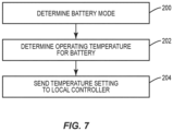
- Figure 7 illustrates a process by which the system controller 90 operates to control the temperature of the battery 100.
- the system controller 90 determines the battery mode (block 200). In one example, this is based on input from a user. In another example, the input is received from an upstream controller that monitors a larger overall process.
- the battery mode is determined by the system controller 90 based on sensed data including but not limited to amount of charge remaining in the battery 100, current charge demand on the battery 100, and the time since last recharging.
- the system controller 90 determines the operating temperature for the battery 100 (block 202). For a capacity control mode, the system controller 90 calculates the setting temperature as with T c being an optimum operating temperature and being the variations above and below that define the allowable operating range. For rate control mode, the system controller 90 calculates the setting temperature as with T r being the optimum temperature and being the variations above and below that define the operating range. Once calculated, the system controller 90 sends the temperature setting to the local controller 60 (block 204).
- the local controller 60 Upon receiving the setting temperatures, the local controller 60 compares the temperature setting to the measured real temperature of the battery 100 and commands the thermoelectric device 20 to cool or heat as necessary.
- the number of operational modes of the battery 100 can vary.
- One example includes two operational modes including a capacity control mode and a rate control mode.
- Another example includes three operational modes include capacity control mode, rate control mode, and an auto mode that switches between capacity control mode and rate control mode depending upon the demands on the battery 100.
- the auto mode operates in both the capacity control mode and the rate control mode based on the mode in which the battery 100 is operating.
- the system controller 90 initially operates in the rate control mode during high speed charging of the battery 100 to save charging time, and then switches to capacity control mode during battery low speed charging phase to maximize charging capacity.
- One example includes a constant current - constant voltage charging method for charging a lithium rechargeable battery. Constant current (CC) is the high speed charging phase, and constant voltage (CV) is the low speed charging phase. The method first performs CC charging before the battery voltage reaches a predetermined value, and then switches to CV until charging current decreases to a setting point.
- the system controller 90 first sets the mode as capacity control mode. During the capacity control mode, the system controller 90 senses the load characteristics. If the load shows frequently high current discharge pulses, then the system controller 90 will switch to the rate control mode. Later if the load shows less frequency of high current discharge, then the system controller 90 will switch back to the capacity control mode.
- the system controller 90 can also provide for a manual mode.
- the manual mode includes receiving the temperature setting from the user.
- the input includes a specific temperature setting and the system controller 90 determines a range (i.e., +/- d).
- the user input includes a range of temperatures.
- the power conditioner 50 and the local controller 60 are incorporated into a control unit 70.
- the control unit 70 includes control circuitry 71 and a memory circuitry 72.
- the control circuitry 71 controls overall operation of the system 10 according to program instructions stored in the memory circuitry 72.
- the control circuitry 71 can include one or more circuits, microcontrollers, microprocessors, hardware, or a combination thereof.
- Memory circuitry 72 includes a non-transitory computer readable storage medium storing program instructions, such as a computer program product, that configures the control circuitry 71 to implement one or more of the techniques discussed herein.
- Memory circuitry 72 can include various memory devices such as, for example, read-only memory, and flash memory.
- a power condition PC module 73 can include instructions for operation of the power conditioner 50 and a controller C module 74 can include instructions for operation of the controller 60.
- Other examples include common modules for operation of these components.
- the control circuitry 71 can omit the memory circuitry 72, e.g., according to at least some embodiments in which the control circuitry 71 is dedicated and non-programmable.
- Communication circuitry 75 provides for receiving one or more inputs for operation of the system 10. Inputs can include but are not limited to inputs regarding operation of the battery 100, temperatures inputs, and user commands.
- the power conditioner 50 and the controller 60 are separate. Each includes control circuitry and memory circuitry and is configured to provide for operation of their specific component. Power may be supplied to operate one or more of the power conditioner 50, controller 60, and control unit 70. The power can be supplied from one or more of the battery 100 and a power bus 110, such as a DC bus, to which the battery 100 is electrically connected. In another example, one or more of the components are powered by a separate power source 79, such as a battery.
- the system 10 includes a single thermoelectric device 20 to heat and/or cool the battery 100.
- Other examples can include two or more thermoelectric devices 20 positioned to heat and/or cool the battery 100.
- the thermoelectric devices 20 can be the same or different.
Landscapes
- Engineering & Computer Science (AREA)
- General Chemical & Material Sciences (AREA)
- Manufacturing & Machinery (AREA)
- Chemical & Material Sciences (AREA)
- Chemical Kinetics & Catalysis (AREA)
- Electrochemistry (AREA)
- Physics & Mathematics (AREA)
- Automation & Control Theory (AREA)
- Electromagnetism (AREA)
- Microelectronics & Electronic Packaging (AREA)
- Algebra (AREA)
- General Physics & Mathematics (AREA)
- Mathematical Analysis (AREA)
- Mathematical Optimization (AREA)
- Pure & Applied Mathematics (AREA)
- Secondary Cells (AREA)
- Charge And Discharge Circuits For Batteries Or The Like (AREA)
Abstract
Description
- The present disclosure relates generally to the field of managing a battery and, more specifically to operating a battery within a temperature range.
- Battery performance including rate of charge or discharge, and capacity of charge or discharge, is affected by operating temperatures. Typically, high temperatures result in faster cell aging and capacity fading that potentially lead to a thermal runaway. Low temperatures result in higher voltage drop inside the cell because of a larger equivalent internal resistance and thus lower output power capability. Use in low temperatures can result in lower useful capacity and can also limit the rate of charge or discharge due to a reduced mobility of ions and increased viscosity of electrolyte.
- Typical battery thermal management systems are not designed and operated for achieving an optimum capacity and/or an optimum rate of charge and discharge. The systems include a thermal management method that cools by liquid or forced air, and heats by use of a heat exchanger and external heating. Issues with these systems is they are often bulky that reduces the contexts in which they can be used. These systems are also limited to contexts that are not sensitive to weight/volume control.
- Thus, there is a need for systems configured to keep a battery in a desired temperature range during operation. Operation within the temperature range can result in better charge and discharge capacity, high power rate, lower aging rate, and higher reliability.
- One aspect is directed to a system for heating and cooling a battery for the battery to operate within a temperature range. The system comprises a thermoelectric device configured to attach to the battery and operate in a heating mode to elevate the operating temperature of the battery and in a cooling mode to reduce the operating temperature of the battery. Control circuitry is configured to: determine a temperature of the battery; supply an input voltage and a polarity of the thermoelectric device; and adjust the input voltage and the polarity based on a temperature of the battery.
- In another aspect, the control circuitry comprises: a power conditioner that supplies the input voltage and the polarity of the thermoelectric device; and a local controller that adjusts the input voltage and the polarity based on the operating temperature of the battery.
- In another aspect, a thermally conductive wrap is configured to contact against individual cells of the battery and conduct heat from the thermoelectric device to the individual cells when operating in the heating mode and conducts the heat from the individual cells to the thermoelectric device when operating in the cooling mode.
- In another aspect, a sensor is configured to sense the temperature of the battery and transmit a corresponding signal to the control circuitry.
- In another aspect, the control circuitry comprises a local controller and further comprises a system controller configured to receive a user input and to transmit a temperature setting point to the local controller.
- In another aspect, the system controller determines whether the battery should be in one of capacity control mode and rate control mode.
- In another aspect, the system controller is further configured to operate in an auto mode that switches between the capacity control mode and the rate control mode based on a load on the battery, and a manual temperature setting mode in which the temperature of the battery is set based on user input.
- In another aspect, the control circuitry further comprises: a DC/DC converter; and an H-bridge to adjust a polarity of the input voltage of the thermoelectric device.
- In another aspect, the thermoelectric device is configured to act in the heating mode in a first polarity and to act in the cooling mode in a second polarity.
- One aspect is directed to a system for heating and cooling a battery for the battery to operate within a temperature range. The system comprises: a thermoelectric device that heats the battery when operated in a first polarity and that cools the battery when operated in a second polarity; a control unit comprising control circuitry configured to monitor a temperature of the battery and determine a temperature setting for the battery; control operation of the thermoelectric device between the first polarity and the second polarity and adjust a voltage supplied to the thermoelectric device to maintain the battery operating within the temperature range.
- In another aspect, the control unit comprises: a power conditioner comprising a DC/DC converter and an H-bridge; and a local controller that receives signals from a sensor at the battery to monitor the temperature of the battery.
- In another aspect, the thermoelectric device comprises an array of n-type and p-type semiconductor materials that are electrically and thermally connected together and positioned between opposing plates.
- In another aspect, the control unit further comprises: a DC/DC converter; and an H-bridge to adjust the polarity of the thermoelectric device.
- In another aspect, a system controller is located remotely from the control unit with the system controller comprising system control circuitry configured to: receive user input; based on the user input, determine when the battery should be in one of capacity control mode and rate control mode.
- In another aspect, a thermally conductive wrap is configured to contact against individual cells of the battery and conduct heat from the thermoelectric device to heat the individual cells when operating in one of the polarities and conduct the heat from the individual cells to the thermoelectric device when operating in a second one of the polarities.
- In another aspect, a power source provides power to the control unit.
- One aspect is directed to a method of regulating a temperature of a battery with the method comprising: determining a temperature range for the battery; monitoring a temperature of the battery; when the temperature is below the temperature range, operating a thermoelectric device thermally connected to the battery in a first polarity and heating the battery; and when the temperature is above the temperature range, operating the thermoelectric device in a second polarity and cooling the battery.
- In another aspect, the method comprises receiving user input and determining the temperature range based on the user input.
- In another aspect, the method comprises determining an operating mode of the battery and determining the temperature range based on the operating mode.
- In another aspect, the method comprises determining the temperature range for the battery based on whether operating in a rate-optimizing charging mode or a capacity-optimizing charging mode.
- The features, functions and advantages that have been discussed can be achieved independently in various aspects or may be combined in yet other aspects, further details of which can be seen with reference to the following description and the drawings.
-
-
Figure 1 is a schematic diagram of a system for controlling a temperature of a battery. -
Figure 2A is a schematic diagram of a thermoelectric device thermally connected to a battery and operating in a cooling mode. -
Figure 2B is a schematic diagram of the thermoelectric device ofFigure 2A operating in a heating mode. -
Figure 3 is a schematic diagram of a system for controlling the temperature of a battery. -
Figure 4 is a schematic diagram of a system for controlling the temperature of a battery. -
Figure 5A is a schematic diagram of a determination of the mode values to set the operational mode of a thermoelectric device. -
Figure 5B is a schematic diagram of a determination of a duty ratio. -
Figure 6 is a schematic diagram of a local controller. -
Figure 7 is a flowchart diagram of a method of steps to control a temperature of a battery. -
Figure 8 is a schematic diagram of a control unit. -
Figure 1 schematically illustrates asystem 10 for controlling a temperature of abattery 100. Athermoelectric device 20 is positioned to heat and/or cool thebattery 100. Apower conditioner 50 is operatively connected to thethermoelectric device 20. Thepower conditioner 50 regulates an input voltage and a polarity of the input voltage to thethermoelectric device 20. Alocal controller 60 determines a mode for thebattery 100 and an operating temperature range. Thelocal control 60 controls thepower conditioner 50 to set the polarity and input voltage based on the need to cool or heat thebattery 100 to operate within the temperature range. - The
thermoelectric device 20 is positioned to heat or cool thebattery 100.Figure 2A illustrates an example of athermoelectric device 20 that includes anarray 21 of alternating n- and p- type semiconductors that are positioned betweenopposing plates array 21 of semiconductors are soldered between theplates plates plates heat sink 24 that includes an exposed surface area such as fins can be attached to theouter plate 23 to further facilitate the heat transfer. In one example, theplates -
Figure 2A illustrates thethermoelectric device 20 operating in cooling mode to remove heat from thebattery 100. Theplate 22 is positioned in thermal contact with thebattery 100. Electric energy is supplied to theplates battery 100 to be removed through the contact with theplate 22. The heat is then thermally conducted through thearray 21 and to theplate 23 where it is released directly into the environment and/or through theheat sink 24. - The polarity of the supplied electric energy can be reversed for the
thermoelectric device 20 to operate in a heating mode. As illustrated inFigure 2B , the reversed polarity provides for heat to be collected at theplate 23 directly from the environment and/or through theheat sink 24. The heat is transferred through thearray 21 andplate 22 to thebattery 100. -
Figure 3 illustrates an example of thesystem 10 connected to abattery 100 to control a temperature of thebattery 100. In this example, thebattery 100 includes a series of pouch orprismatic battery cells 101. In another example, the battery includes a series of cylindrical cells. - A
wrap 40 is positioned on a portion or entirety of thebattery 100. Thewrap 40 is thermally conductive and provides for the transfer of heat. Thewrap 40 can have a variety of constructions including but not limited to a pyrolytic graphite sheet and a carbon nanotube material. In one example as illustrated inFigure 3 , thewrap 40 snakes around and contacts against one or more of the surfaces thecells 101. Additionally or alternatively, thewrap 40 extends around a portion or entirety of the exterior of thebattery 100. Thewrap 40 can be positioned against thethermoelectric device 20 or can be spaced away from thethermoelectric device 20. - The
thermoelectric device 20 is positioned to heat and/or cool thebattery 100.Figure 3 includes thedevice 20 mounted on a side of the other, although thedevice 20 can be positioned at a variety of different locations relative to thebattery 100. - The
power conditioner 50 is electrically connected to thethermoelectric device 20. Thepower conditioner 50 regulates the magnitude of the input voltage supplied to thethermoelectric device 20. Thepower conditioner 50 also regulates the polarity of the input voltage to control the operational mode of thethermoelectric device 20 and whether it operates in heating mode to supply heat to thebattery 100 or cooling mode to remove heat. -
Figure 4 includes an example with thepower conditioner 50 having aconverter 51. Theconverter 51 is a DC/DC converter that regulates the output voltage per duty ratio. Thepower conditioner 50 also includes aswitcher 52 to vary the polarization of the voltage inputs to change the operational mode of thethermoelectric device 20. Theswitcher 52 includes an H-bridge with multiple switches that can be set to control the voltage output. - The
local controller 60 determines whether thethermoelectric device 20 operates in the heating mode or the cooling mode. Thelocal controller 60 also monitors the temperature of thebattery 100 and maintains the temperature within a desired operating range to achieve increased performance of thebattery 100. In one example, thelocal controller 60 receives an input indicating the operation of thebattery 100 and thus determines the operating point to achieve the desired performance for charge or discharge rate, capacity, or both. Thelocal controller 60 receives signals from asensor 80 that is positioned to sense a temperature of thebattery 100. This sensed temperature is used by thelocal controller 60 to operate thepower conditioner 50 to remain within the desired temperature range. - The
local controller 60 further uses the temperature of thebattery 100 received from thesensor 80, and the inputs from thesystem controller 90 to calculate the operational commands for thethermoelectric device 20. Thelocal controller 60 calculates the outputs the mode values and the duty ratio for operation of thethermoelectric device 20. - As illustrated in
Figure 4 , asystem controller 90 is positioned upstream from thelocal controller 60. Thesystem controller 90 sends data to thelocal controller 60 for operation of thethermoelectric device 20. In one example, thesystem controller 90 sends a temperature setting point and an operational temperature range of thebattery 100. The data can be stored at thesystem controller 90 in an autonomous system and/or received as input through user commands. -
Figure 5A schematically illustrates the determination of the mode values that are used to set the operational mode of thethermoelectric device 20. These calculations are based on the temperature setting point Ts, a temperature tolerance from the setting point, and the sensed temperature (Temp). One or both of the
local controller 60 andsystem controller 90 calculates the mode using the following logic: - If

- If

- If Temp > (Ts + d), then Mode = 1 (cooling mode)
-
Figure 5B schematically illustrates the determination of the duty ratio calculated by one or both of thelocal controller 60 and thesystem controller 90. The determination sets the constant K for the slope of the duty ratio control. The duty ratio calculations include the following: - If

- If

- If

-
Figure 6 illustrates a functional implementation diagram of thelocal controller 60. Thelocal controller 60 receives as an input a temperature setting for thethermoelectric device 20. Thelocal controller 60 includes a look-up table 61 that includes a duty ratio calculation and a mode selection for different temperature setting points. Amode selector 62 output signals to operates the switches of the H-bridge switcher 52. Themode selector 62 calculates the following: - If Mode = -1, then SW1 and SW4 = ON, SW2 and SW3 = OFF, working in heating mode
- If Mode = 0, then SW1 to SW4 = OFF, working in idle mode with no heating or cooling
- If Mode = 1, then SW1 and SW$ = OFF, SW2 and SW3 = ON, working in cooling mode
- The
local controller 60 also includes a pulsewidth modulation generator 63.PWM generator 63 provides a PWM signal that controls theconverter 51 of thepower conditioner 50 to regulate the output voltage per duty ratio value. - In one example, the
system controller 90 determines when thebattery 100 should operate in capacity control mode or in rate control mode.Figure 7 illustrates a process by which thesystem controller 90 operates to control the temperature of thebattery 100. Thesystem controller 90 determines the battery mode (block 200). In one example, this is based on input from a user. In another example, the input is received from an upstream controller that monitors a larger overall process. In another example, the battery mode is determined by thesystem controller 90 based on sensed data including but not limited to amount of charge remaining in thebattery 100, current charge demand on thebattery 100, and the time since last recharging. - The
system controller 90 determines the operating temperature for the battery 100 (block 202). For a capacity control mode, thesystem controller 90 calculates the setting temperature as being the variations above and below that define the allowable operating range. For rate control mode, the
system controller 90 calculates the setting temperature as being the variations above and below that define the operating range. Once calculated, the
system controller 90 sends the temperature setting to the local controller 60 (block 204). - Upon receiving the setting temperatures, the
local controller 60 compares the temperature setting to the measured real temperature of thebattery 100 and commands thethermoelectric device 20 to cool or heat as necessary. - The number of operational modes of the
battery 100 can vary. One example includes two operational modes including a capacity control mode and a rate control mode. Another example includes three operational modes include capacity control mode, rate control mode, and an auto mode that switches between capacity control mode and rate control mode depending upon the demands on thebattery 100. - The auto mode operates in both the capacity control mode and the rate control mode based on the mode in which the
battery 100 is operating. During the auto mode when thebattery 100 is being charged from an external source, thesystem controller 90 initially operates in the rate control mode during high speed charging of thebattery 100 to save charging time, and then switches to capacity control mode during battery low speed charging phase to maximize charging capacity. One example includes a constant current - constant voltage charging method for charging a lithium rechargeable battery. Constant current (CC) is the high speed charging phase, and constant voltage (CV) is the low speed charging phase. The method first performs CC charging before the battery voltage reaches a predetermined value, and then switches to CV until charging current decreases to a setting point. - During the auto mode when the
battery 100 is in a discharging phase to serve a load, thesystem controller 90 first sets the mode as capacity control mode. During the capacity control mode, thesystem controller 90 senses the load characteristics. If the load shows frequently high current discharge pulses, then thesystem controller 90 will switch to the rate control mode. Later if the load shows less frequency of high current discharge, then thesystem controller 90 will switch back to the capacity control mode. - The
system controller 90 can also provide for a manual mode. The manual mode includes receiving the temperature setting from the user. In one example, the input includes a specific temperature setting and thesystem controller 90 determines a range (i.e., +/- d). In another example, the user input includes a range of temperatures. - In one example, the
power conditioner 50 and thelocal controller 60 are incorporated into acontrol unit 70. As illustrated inFigure 8 , thecontrol unit 70 includescontrol circuitry 71 and amemory circuitry 72. Thecontrol circuitry 71 controls overall operation of thesystem 10 according to program instructions stored in thememory circuitry 72. Thecontrol circuitry 71 can include one or more circuits, microcontrollers, microprocessors, hardware, or a combination thereof.Memory circuitry 72 includes a non-transitory computer readable storage medium storing program instructions, such as a computer program product, that configures thecontrol circuitry 71 to implement one or more of the techniques discussed herein.Memory circuitry 72 can include various memory devices such as, for example, read-only memory, and flash memory. In one example, a powercondition PC module 73 can include instructions for operation of thepower conditioner 50 and acontroller C module 74 can include instructions for operation of thecontroller 60. Other examples include common modules for operation of these components. In another example, thecontrol circuitry 71 can omit thememory circuitry 72, e.g., according to at least some embodiments in which thecontrol circuitry 71 is dedicated and non-programmable. -
Communication circuitry 75 provides for receiving one or more inputs for operation of thesystem 10. Inputs can include but are not limited to inputs regarding operation of thebattery 100, temperatures inputs, and user commands. - In another example (not illustrated), the
power conditioner 50 and thecontroller 60 are separate. Each includes control circuitry and memory circuitry and is configured to provide for operation of their specific component. Power may be supplied to operate one or more of thepower conditioner 50,controller 60, andcontrol unit 70. The power can be supplied from one or more of thebattery 100 and apower bus 110, such as a DC bus, to which thebattery 100 is electrically connected. In another example, one or more of the components are powered by aseparate power source 79, such as a battery. - In one example, the
system 10 includes a singlethermoelectric device 20 to heat and/or cool thebattery 100. Other examples can include two or morethermoelectric devices 20 positioned to heat and/or cool thebattery 100. Thethermoelectric devices 20 can be the same or different. - Further, the disclosure comprises embodiments according to the following clauses:
- Clause 1. A system to heat and cool a
battery 100 for thebattery 100 to operate within a temperature range, the system comprising:- a
thermoelectric device 20 configured to attach to thebattery 100 and operate in a heating mode to elevate an operating temperature of thebattery 100 and in a cooling mode to reduce the operating temperature of thebattery 100; -
control circuitry 71 configured to:- determine a temperature of the
battery 100; - supply an input voltage and a polarity of the
thermoelectric device 20; and
- determine a temperature of the
battery 100. - a
- Clause 2. The system of Clause 1, wherein the
control circuitry 71 comprises:- a
power conditioner 50 that supplies the input voltage and the polarity of thethermoelectric device 20; and - a
local controller 60 that adjusts the input voltage and the polarity based on the operating temperature of thebattery 100.
- a
- Clause 3. The system of Clause 1 or 2, further comprising a thermally
conductive wrap 40 configured to contact againstindividual cells 101 of thebattery 100 and conducts heat from thethermoelectric device 20 to theindividual cells 101 when operating in the heating mode and conducts the heat from theindividual cells 101 to thethermoelectric device 20 when operating in the cooling mode. - Clause 4. The system of any one of Clauses 1-3, further comprising a
sensor 80 configured to sense the temperature of thebattery 100 and transmit a corresponding signal to the control circuitry. - Clause 5. The system of any one of Clause 1-4, wherein the
control circuitry 71 comprises alocal controller 60 and further comprising asystem controller 90 configured to receive a user input and to transmit a temperature setting point to thelocal controller 60. - 6. The system of Clause 5, wherein the system controller determines when the battery should is in one of a capacity control mode and a rate control mode.
- Clause 7. The system of
Clause 6, wherein the system controller is further configured to operate in an auto mode that switches between the capacity control mode and the rate control mode based on a load on the battery, and a manual temperature setting mode in which the temperature of the battery is set based on user input. -
Clause 8. The system of any one of Clauses 1-7, wherein thecontrol circuitry 71 further comprises:- a DC/
DC converter 51; and - an H-
bridge 52 to adjust a polarity of the input voltage of thethermoelectric device 20.
- a DC/
- Clause 9. The system of any one of Clauses 1-8, wherein the
thermoelectric device 20 is configured to act in the heating mode in a first polarity and to act in the cooling mode in a second polarity. -
Clause 10. A system to heat and cool abattery 100 for thebattery 100 to operate within a temperature range, the system comprising:- a
thermoelectric device 20 that heats thebattery 100 when operated in a first polarity and that cools thebattery 100 when operated in a second polarity; and - a
control unit 70 comprisingcontrol circuitry 71 configured to:- monitor a temperature of the
battery 100; - determine a temperature setting for the
battery 100;
- monitor a temperature of the
thermoelectric device 20 between the first polarity and the second polarity and adjust a voltage supplied to thethermoelectric device 20 to maintain thebattery 100 operating within the temperature range. - a
- Clause 11. The system of
Clause 10, wherein the control unit comprises:
apower conditioner 50 comprising a DC/DC converter 51 and an H-bridge 52; and
alocal controller 60 that receives signals from asensor 80 at thebattery 100 to monitor the temperature of thebattery 100. - Clause 12. The system of
Clause 10 or 11, wherein thethermoelectric device 20 comprises an array of n-type and p-type semiconductor materials 21 that are electrically and thermally connected together and positioned between opposingplates - Clause 13. The system of any one of Clauses 10-12, wherein the
control unit 70 further comprises:- a DC/
DC converter 51; and - an H-
bridge 52 to adjust a polarity of thethermoelectric device 20.
- a DC/
- Clause 14. The system of any one of Clauses 10-13, further comprising a
system controller 90 located remotely from thecontrol unit 70, thesystem controller 90 comprising system control circuitry configured to:- receive user input;
- based on the user input, determine when the
battery 100 is in one of capacity control mode and rate control mode.
- Clause 15. The system of any one of Clauses 10-14, further comprising a thermally
conductive wrap 40 configured to contact againstindividual cells 101 of thebattery 100 and conduct heat from thethermoelectric device 20 to heat theindividual cells 101 when operating in one of the first and second polarities and conduct the heat from theindividual cells 101 to thethermoelectric device 20 when operating in a second one of the polarities. - Clause 16. The system of any one of Clauses 10-15, further comprising a
power source 79 to provide power to thecontrol unit 70. - Clause 17. A method of regulating a temperature of a
battery 100, the method comprising:- determining a temperature range for the
battery 100; - monitoring a temperature of the
battery 100; - when the temperature is below the temperature range, operating a
thermoelectric device 20 thermally connected to thebattery 100 in a first polarity and heating thebattery 100; and - when the temperature is above the temperature range, operating the
thermoelectric device 20 in a second polarity and cooling thebattery 100.
- determining a temperature range for the
- Clause 18. The method of Clause 17, further comprising receiving user input and determining the temperature range based on the user input.
- Clause 19. The method of Clause 17 or 18, further comprising determining an operating mode of the
battery 100 and determining the temperature range based on the operating mode. -
Clause 20. The method of any one of Clauses 17-19, further comprising determining the temperature range for thebattery 100 based on operating in one of a rate-optimizing charging mode and a capacity-optimizing charging mode. - The present invention may be carried out in other ways than those specifically set forth herein without departing from essential characteristics of the invention. The present embodiments are to be considered in all respects as illustrative and not restrictive, and all changes coming within the meaning and equivalency range of the appended claims are intended to be embraced therein.
Claims (15)
- A system (10) to heat and cool a battery (100) for the battery (100) to operate within a temperature range, the system (10) comprising:a thermoelectric device (20) configured to attach to the battery (100) and operate in a heating mode to elevate an operating temperature of the battery (100) and in a cooling mode to reduce the operating temperature of the battery (100);a control circuitry (71) configured to:adjust the input voltage and the polarity based on a temperature of the battery (100).determine a temperature of the battery (100);supply an input voltage and a polarity of the thermoelectric device (20); and
- The system (10) of claim 1, wherein the control circuitry (71) comprises:a power conditioner (50) configured to supply the input voltage and the polarity of the thermoelectric device (20); anda local controller (60) configured to adjust the input voltage and the polarity based on the operating temperature of the battery (100).
- The system (10) of claim 1 or 2, further comprising a thermally conductive wrap (40) configured to contact against individual cells (101) of the battery (100) and conducts heat from the thermoelectric device (20) to the individual cells (101) when operating in the heating mode and conducts the heat from the individual cells (101) to the thermoelectric device (20) when operating in the cooling mode.
- The system (10) of any one of the preceding claims, further comprising a sensor (80) configured to sense the temperature of the battery (100) and transmit a corresponding signal to the control circuitry (71).
- The system (10) of claim 1, wherein the control circuitry (71) comprises a local controller (60) and further comprising a system controller (90) configured to receive a user input and to transmit a temperature setting point to the local controller (60).
- The system (10) of claim 5, wherein the system controller (90) determines when the battery (100) is in one of a capacity control mode and a rate control mode.
- The system (10) of claim 6, wherein the system controller (90) is further configured to operate the battery (100) in an auto mode that switches between the capacity control mode and the rate control mode based on a load on the battery (100), and a manual temperature setting mode in which the temperature of the battery (100) is set based on user input.
- The system (10) of claim 1, wherein the control circuitry (71) further comprises:a DC/DC converter (51); andan H-bridge (52) to adjust a polarity of the input voltage of the thermoelectric device (20).
- The system (10) of any one of the preceding claims, wherein the thermoelectric device (20) is configured to act in the heating mode in a first polarity and to act in the cooling mode in a second polarity.
- A method of regulating a temperature of a battery (100), the method comprising:determining a temperature range for the battery (100);monitoring a temperature of the battery (100);when the temperature is below the temperature range, operating a thermoelectric device (20) thermally connected to the battery (100) in a first polarity and heating the battery (100); andwhen the temperature is above the temperature range, operating the thermoelectric device (20) in a second polarity and cooling the battery (100).
- The method of claim 10, further comprising receiving user input and determining the temperature range based on the user input.
- The method of claim 10 or 11, further comprising determining an operating mode of the battery (100) and determining the temperature range based on the operating mode.
- The method of any one of claims 10-12, further comprising determining the temperature range for the battery (100) based on operating in one of a rate-optimizing charging mode and a capacity-optimizing charging mode.
- The method of any one of claims 10-13, further comprising utilizing a sensor (80) configured to sense the temperature of the battery (100) and transmit a corresponding signal to a control circuitry (71).
- The method of any one of claims 10-14, further comprising adjusting the input voltage and the polarity of the battery (100) based on the operating temperature of the battery (100).
Applications Claiming Priority (1)
| Application Number | Priority Date | Filing Date | Title |
|---|---|---|---|
| US17/750,682 US20230378569A1 (en) | 2022-05-23 | 2022-05-23 | Battery Temperature Regulation System |
Publications (1)
| Publication Number | Publication Date |
|---|---|
| EP4283763A1 true EP4283763A1 (en) | 2023-11-29 |
Family
ID=86382877
Family Applications (1)
| Application Number | Title | Priority Date | Filing Date |
|---|---|---|---|
| EP23173477.3A Pending EP4283763A1 (en) | 2022-05-23 | 2023-05-15 | Battery temperature regulation system |
Country Status (2)
| Country | Link |
|---|---|
| US (1) | US20230378569A1 (en) |
| EP (1) | EP4283763A1 (en) |
Families Citing this family (1)
| Publication number | Priority date | Publication date | Assignee | Title |
|---|---|---|---|---|
| DE102024112818A1 (en) | 2024-05-07 | 2025-11-13 | Bayerische Motoren Werke Aktiengesellschaft | Means of transport, device and method for energy-saving charging of an electrochemical energy storage device |
Citations (3)
| Publication number | Priority date | Publication date | Assignee | Title |
|---|---|---|---|---|
| US20170200992A1 (en) * | 2014-09-12 | 2017-07-13 | Gentherm Incorporated | Graphite thermoelectric and/or resistive thermal management systems and methods |
| US20200227801A1 (en) * | 2018-05-07 | 2020-07-16 | Saurav Kumar | Active rechargeable battery thermal management system |
| EP3817126A1 (en) * | 2019-11-04 | 2021-05-05 | Samsung SDI Co., Ltd. | Battery pack and control method thereof |
Family Cites Families (7)
| Publication number | Priority date | Publication date | Assignee | Title |
|---|---|---|---|---|
| JP2003007356A (en) * | 2001-06-25 | 2003-01-10 | Matsushita Refrig Co Ltd | Temperature regulator for storage battery and running vehicle mounting the same |
| WO2011138156A1 (en) * | 2010-05-07 | 2011-11-10 | Siemens Aktiengesellschaft | Electrical energy store and cooling device |
| US10889162B2 (en) * | 2018-11-16 | 2021-01-12 | Toyota Motor Engineering & Manufacturing North America, Inc. | Vehicle component cooling through directed HVAC cooling and operation |
| CN111244572A (en) * | 2020-01-22 | 2020-06-05 | 恒大新能源汽车科技(广东)有限公司 | Battery pack temperature difference control system, control method and electronic equipment |
| GB202001012D0 (en) * | 2020-01-24 | 2020-03-11 | Ocado Innovation Ltd | Raising and lowering containers |
| CN111584971A (en) * | 2020-04-26 | 2020-08-25 | 东风汽车集团有限公司 | Power battery thermal management system |
| US12567621B2 (en) * | 2022-05-09 | 2026-03-03 | Rivian Ip Holdings, Llc | Thermal system |
-
2022
- 2022-05-23 US US17/750,682 patent/US20230378569A1/en active Pending
-
2023
- 2023-05-15 EP EP23173477.3A patent/EP4283763A1/en active Pending
Patent Citations (3)
| Publication number | Priority date | Publication date | Assignee | Title |
|---|---|---|---|---|
| US20170200992A1 (en) * | 2014-09-12 | 2017-07-13 | Gentherm Incorporated | Graphite thermoelectric and/or resistive thermal management systems and methods |
| US20200227801A1 (en) * | 2018-05-07 | 2020-07-16 | Saurav Kumar | Active rechargeable battery thermal management system |
| EP3817126A1 (en) * | 2019-11-04 | 2021-05-05 | Samsung SDI Co., Ltd. | Battery pack and control method thereof |
Also Published As
| Publication number | Publication date |
|---|---|
| US20230378569A1 (en) | 2023-11-23 |
Similar Documents
| Publication | Publication Date | Title |
|---|---|---|
| US6163086A (en) | Power supply circuit and a voltage level adjusting circuit and method for a portable battery-powered electronic device | |
| US9093847B2 (en) | Temperature controlled parallel balancing | |
| KR102667239B1 (en) | Method and a battery system for thermal management | |
| US7446508B2 (en) | Battery charger for charging lithium-ion battery | |
| EP3531497B1 (en) | Battery pack temperature control method and device | |
| US6459237B1 (en) | Battery charger apparatus and method | |
| EP3817126B1 (en) | Battery pack and control method thereof | |
| KR20230005943A (en) | Electric vehicle, its control system and electric heating device | |
| CN1312821C (en) | Charging rate regulator circuit of battery | |
| RU2403656C1 (en) | Method of using lithium-ion accumulator battery in artificial earth satellite | |
| EP4283763A1 (en) | Battery temperature regulation system | |
| KR102401539B1 (en) | Apparatus and method for cell balancing | |
| US11646597B2 (en) | Fast charging for lithium-ion batteries using pulse width modulated charging and cooling | |
| WO2019008367A1 (en) | BATTERY MANAGEMENT | |
| JP7610545B2 (en) | Secondary battery system, control device for secondary battery system, control method, and program | |
| WO2025228129A1 (en) | Charge-discharge system | |
| EP4002553B1 (en) | Battery temperature control apparatus, battery system, energy storage system and battery temperature control method | |
| Alaoui | Modular energy efficient and solid-state Battery Thermal Management System | |
| WO2025021700A1 (en) | Battery system | |
| JP2001314045A (en) | Charging device | |
| US20240275201A1 (en) | Bidirectional Adaptive Terminal Voltage (BATV) with a Battery Pack | |
| KR20150033126A (en) | Apparatus for controlling temperature of battery pack | |
| US20250226462A1 (en) | Battery pack | |
| JPH0837736A (en) | Battery control device | |
| GB2631103A (en) | Independent battery apparatus |
Legal Events
| Date | Code | Title | Description |
|---|---|---|---|
| PUAI | Public reference made under article 153(3) epc to a published international application that has entered the european phase |
Free format text: ORIGINAL CODE: 0009012 |
|
| STAA | Information on the status of an ep patent application or granted ep patent |
Free format text: STATUS: THE APPLICATION HAS BEEN PUBLISHED |
|
| AK | Designated contracting states |
Kind code of ref document: A1 Designated state(s): AL AT BE BG CH CY CZ DE DK EE ES FI FR GB GR HR HU IE IS IT LI LT LU LV MC ME MK MT NL NO PL PT RO RS SE SI SK SM TR |
|
| STAA | Information on the status of an ep patent application or granted ep patent |
Free format text: STATUS: REQUEST FOR EXAMINATION WAS MADE |
|
| 17P | Request for examination filed |
Effective date: 20240527 |
|
| RBV | Designated contracting states (corrected) |
Designated state(s): AL AT BE BG CH CY CZ DE DK EE ES FI FR GB GR HR HU IE IS IT LI LT LU LV MC ME MK MT NL NO PL PT RO RS SE SI SK SM TR |