EP4283760A1 - Coolant distribution arrangement and system for cooling vehicle propulsion batteries - Google Patents
Coolant distribution arrangement and system for cooling vehicle propulsion batteries Download PDFInfo
- Publication number
- EP4283760A1 EP4283760A1 EP22175277.7A EP22175277A EP4283760A1 EP 4283760 A1 EP4283760 A1 EP 4283760A1 EP 22175277 A EP22175277 A EP 22175277A EP 4283760 A1 EP4283760 A1 EP 4283760A1
- Authority
- EP
- European Patent Office
- Prior art keywords
- coolant
- cooling system
- manifold section
- arrangement
- deairing
- Prior art date
- Legal status (The legal status is an assumption and is not a legal conclusion. Google has not performed a legal analysis and makes no representation as to the accuracy of the status listed.)
- Granted
Links
Images



Classifications
-
- B—PERFORMING OPERATIONS; TRANSPORTING
- B60—VEHICLES IN GENERAL
- B60K—ARRANGEMENT OR MOUNTING OF PROPULSION UNITS OR OF TRANSMISSIONS IN VEHICLES; ARRANGEMENT OR MOUNTING OF PLURAL DIVERSE PRIME-MOVERS IN VEHICLES; AUXILIARY DRIVES FOR VEHICLES; INSTRUMENTATION OR DASHBOARDS FOR VEHICLES; ARRANGEMENTS IN CONNECTION WITH COOLING, AIR INTAKE, GAS EXHAUST OR FUEL SUPPLY OF PROPULSION UNITS IN VEHICLES
- B60K11/00—Arrangement in connection with cooling of propulsion units
- B60K11/02—Arrangement in connection with cooling of propulsion units with liquid cooling
-
- B—PERFORMING OPERATIONS; TRANSPORTING
- B60—VEHICLES IN GENERAL
- B60K—ARRANGEMENT OR MOUNTING OF PROPULSION UNITS OR OF TRANSMISSIONS IN VEHICLES; ARRANGEMENT OR MOUNTING OF PLURAL DIVERSE PRIME-MOVERS IN VEHICLES; AUXILIARY DRIVES FOR VEHICLES; INSTRUMENTATION OR DASHBOARDS FOR VEHICLES; ARRANGEMENTS IN CONNECTION WITH COOLING, AIR INTAKE, GAS EXHAUST OR FUEL SUPPLY OF PROPULSION UNITS IN VEHICLES
- B60K1/00—Arrangement or mounting of electrical propulsion units
- B60K1/04—Arrangement or mounting of electrical propulsion units of the electric storage means for propulsion
-
- H—ELECTRICITY
- H01—ELECTRIC ELEMENTS
- H01M—PROCESSES OR MEANS, e.g. BATTERIES, FOR THE DIRECT CONVERSION OF CHEMICAL ENERGY INTO ELECTRICAL ENERGY
- H01M10/00—Secondary cells; Manufacture thereof
- H01M10/60—Heating or cooling; Temperature control
- H01M10/61—Types of temperature control
- H01M10/613—Cooling or keeping cold
-
- H—ELECTRICITY
- H01—ELECTRIC ELEMENTS
- H01M—PROCESSES OR MEANS, e.g. BATTERIES, FOR THE DIRECT CONVERSION OF CHEMICAL ENERGY INTO ELECTRICAL ENERGY
- H01M10/00—Secondary cells; Manufacture thereof
- H01M10/60—Heating or cooling; Temperature control
- H01M10/65—Means for temperature control structurally associated with the cells
- H01M10/655—Solid structures for heat exchange or heat conduction
- H01M10/6556—Solid parts with flow channel passages or pipes for heat exchange
-
- H—ELECTRICITY
- H01—ELECTRIC ELEMENTS
- H01M—PROCESSES OR MEANS, e.g. BATTERIES, FOR THE DIRECT CONVERSION OF CHEMICAL ENERGY INTO ELECTRICAL ENERGY
- H01M10/00—Secondary cells; Manufacture thereof
- H01M10/60—Heating or cooling; Temperature control
- H01M10/65—Means for temperature control structurally associated with the cells
- H01M10/656—Means for temperature control structurally associated with the cells characterised by the type of heat-exchange fluid
- H01M10/6567—Liquids
-
- H—ELECTRICITY
- H01—ELECTRIC ELEMENTS
- H01M—PROCESSES OR MEANS, e.g. BATTERIES, FOR THE DIRECT CONVERSION OF CHEMICAL ENERGY INTO ELECTRICAL ENERGY
- H01M10/00—Secondary cells; Manufacture thereof
- H01M10/60—Heating or cooling; Temperature control
- H01M10/66—Heat-exchange relationships between the cells and other systems, e.g. central heating systems or fuel cells
- H01M10/663—Heat-exchange relationships between the cells and other systems, e.g. central heating systems or fuel cells the system being an air-conditioner or an engine
-
- H—ELECTRICITY
- H01—ELECTRIC ELEMENTS
- H01M—PROCESSES OR MEANS, e.g. BATTERIES, FOR THE DIRECT CONVERSION OF CHEMICAL ENERGY INTO ELECTRICAL ENERGY
- H01M50/00—Constructional details or processes of manufacture of the non-active parts of electrochemical cells other than fuel cells, e.g. hybrid cells
- H01M50/20—Mountings; Secondary casings or frames; Racks, modules or packs; Suspension devices; Shock absorbers; Transport or carrying devices; Holders
- H01M50/249—Mountings; Secondary casings or frames; Racks, modules or packs; Suspension devices; Shock absorbers; Transport or carrying devices; Holders specially adapted for aircraft or vehicles, e.g. cars or trains
-
- B—PERFORMING OPERATIONS; TRANSPORTING
- B60—VEHICLES IN GENERAL
- B60K—ARRANGEMENT OR MOUNTING OF PROPULSION UNITS OR OF TRANSMISSIONS IN VEHICLES; ARRANGEMENT OR MOUNTING OF PLURAL DIVERSE PRIME-MOVERS IN VEHICLES; AUXILIARY DRIVES FOR VEHICLES; INSTRUMENTATION OR DASHBOARDS FOR VEHICLES; ARRANGEMENTS IN CONNECTION WITH COOLING, AIR INTAKE, GAS EXHAUST OR FUEL SUPPLY OF PROPULSION UNITS IN VEHICLES
- B60K1/00—Arrangement or mounting of electrical propulsion units
-
- B—PERFORMING OPERATIONS; TRANSPORTING
- B60—VEHICLES IN GENERAL
- B60K—ARRANGEMENT OR MOUNTING OF PROPULSION UNITS OR OF TRANSMISSIONS IN VEHICLES; ARRANGEMENT OR MOUNTING OF PLURAL DIVERSE PRIME-MOVERS IN VEHICLES; AUXILIARY DRIVES FOR VEHICLES; INSTRUMENTATION OR DASHBOARDS FOR VEHICLES; ARRANGEMENTS IN CONNECTION WITH COOLING, AIR INTAKE, GAS EXHAUST OR FUEL SUPPLY OF PROPULSION UNITS IN VEHICLES
- B60K1/00—Arrangement or mounting of electrical propulsion units
- B60K2001/003—Arrangement or mounting of electrical propulsion units with means for cooling the electrical propulsion units
- B60K2001/005—Arrangement or mounting of electrical propulsion units with means for cooling the electrical propulsion units the electric storage means
-
- B—PERFORMING OPERATIONS; TRANSPORTING
- B60—VEHICLES IN GENERAL
- B60K—ARRANGEMENT OR MOUNTING OF PROPULSION UNITS OR OF TRANSMISSIONS IN VEHICLES; ARRANGEMENT OR MOUNTING OF PLURAL DIVERSE PRIME-MOVERS IN VEHICLES; AUXILIARY DRIVES FOR VEHICLES; INSTRUMENTATION OR DASHBOARDS FOR VEHICLES; ARRANGEMENTS IN CONNECTION WITH COOLING, AIR INTAKE, GAS EXHAUST OR FUEL SUPPLY OF PROPULSION UNITS IN VEHICLES
- B60K1/00—Arrangement or mounting of electrical propulsion units
- B60K1/04—Arrangement or mounting of electrical propulsion units of the electric storage means for propulsion
- B60K2001/0405—Arrangement or mounting of electrical propulsion units of the electric storage means for propulsion characterised by their position
- B60K2001/0438—Arrangement under the floor
-
- B—PERFORMING OPERATIONS; TRANSPORTING
- B60—VEHICLES IN GENERAL
- B60Y—INDEXING SCHEME RELATING TO ASPECTS CROSS-CUTTING VEHICLE TECHNOLOGY
- B60Y2200/00—Type of vehicle
- B60Y2200/10—Road Vehicles
- B60Y2200/14—Trucks; Load vehicles, Busses
-
- B—PERFORMING OPERATIONS; TRANSPORTING
- B60—VEHICLES IN GENERAL
- B60Y—INDEXING SCHEME RELATING TO ASPECTS CROSS-CUTTING VEHICLE TECHNOLOGY
- B60Y2200/00—Type of vehicle
- B60Y2200/10—Road Vehicles
- B60Y2200/14—Trucks; Load vehicles, Busses
- B60Y2200/143—Busses
-
- B—PERFORMING OPERATIONS; TRANSPORTING
- B60—VEHICLES IN GENERAL
- B60Y—INDEXING SCHEME RELATING TO ASPECTS CROSS-CUTTING VEHICLE TECHNOLOGY
- B60Y2410/00—Constructional features of vehicle sub-units
- B60Y2410/10—Housings
-
- H—ELECTRICITY
- H01—ELECTRIC ELEMENTS
- H01M—PROCESSES OR MEANS, e.g. BATTERIES, FOR THE DIRECT CONVERSION OF CHEMICAL ENERGY INTO ELECTRICAL ENERGY
- H01M10/00—Secondary cells; Manufacture thereof
- H01M10/60—Heating or cooling; Temperature control
- H01M10/61—Types of temperature control
- H01M10/615—Heating or keeping warm
-
- H—ELECTRICITY
- H01—ELECTRIC ELEMENTS
- H01M—PROCESSES OR MEANS, e.g. BATTERIES, FOR THE DIRECT CONVERSION OF CHEMICAL ENERGY INTO ELECTRICAL ENERGY
- H01M10/00—Secondary cells; Manufacture thereof
- H01M10/60—Heating or cooling; Temperature control
- H01M10/62—Heating or cooling; Temperature control specially adapted for specific applications
- H01M10/625—Vehicles
-
- H—ELECTRICITY
- H01—ELECTRIC ELEMENTS
- H01M—PROCESSES OR MEANS, e.g. BATTERIES, FOR THE DIRECT CONVERSION OF CHEMICAL ENERGY INTO ELECTRICAL ENERGY
- H01M10/00—Secondary cells; Manufacture thereof
- H01M10/60—Heating or cooling; Temperature control
- H01M10/65—Means for temperature control structurally associated with the cells
- H01M10/656—Means for temperature control structurally associated with the cells characterised by the type of heat-exchange fluid
- H01M10/6567—Liquids
- H01M10/6568—Liquids characterised by flow circuits, e.g. loops, located externally to the cells or cell casings
-
- H—ELECTRICITY
- H01—ELECTRIC ELEMENTS
- H01M—PROCESSES OR MEANS, e.g. BATTERIES, FOR THE DIRECT CONVERSION OF CHEMICAL ENERGY INTO ELECTRICAL ENERGY
- H01M2220/00—Batteries for particular applications
- H01M2220/20—Batteries in motive systems, e.g. vehicle, ship, plane
-
- Y—GENERAL TAGGING OF NEW TECHNOLOGICAL DEVELOPMENTS; GENERAL TAGGING OF CROSS-SECTIONAL TECHNOLOGIES SPANNING OVER SEVERAL SECTIONS OF THE IPC; TECHNICAL SUBJECTS COVERED BY FORMER USPC CROSS-REFERENCE ART COLLECTIONS [XRACs] AND DIGESTS
- Y02—TECHNOLOGIES OR APPLICATIONS FOR MITIGATION OR ADAPTATION AGAINST CLIMATE CHANGE
- Y02E—REDUCTION OF GREENHOUSE GAS [GHG] EMISSIONS, RELATED TO ENERGY GENERATION, TRANSMISSION OR DISTRIBUTION
- Y02E60/00—Enabling technologies; Technologies with a potential or indirect contribution to GHG emissions mitigation
- Y02E60/10—Energy storage using batteries
Definitions
- the present application relates cooling of propulsion batteries and in particular propulsion batteries that may be positioned in several positions or clusters in or on a vehicle.
- Battery-operated vehicles are provided with propulsion battery packs for providing enough energy for the operation of the vehicle.
- Propulsion battery packs are known to be sensitive to temperature differences in particular when they are combined in parallel electrical circuits. By keeping all the batteries at even temperatures, the aging of the batteries can be kept under control. A cooling circuit is then designed to provide even temperatures. That is, the coolant flow is guided as a parallel flow to the batteries.
- the propulsion battery pack is placed quite close to the cooling system, including power train and electric machine cooling, radiators, pumps and valves.
- the cooling system can be placed in the rear of the vehicle.
- busses for public transport all propulsion battery packs cannot be placed in the rear of the vehicle and there is limited space available inside the bus in the passenger area. Therefore, some of the propulsion battery packs are placed on the roof of the bus. This poses problems with the coolant distribution from the cooling system in the rear up to the roof of the vehicle.
- One problem is that there also is limited space for conduits for coolant to and from the battery packs on the roof.
- a general concern regarding cooling systems for battery packs is air in the system that needs to be removed in order for the cooling of the batteries to be efficient. This is because air bubbles may be trapped in different locations in the battery packs and the cooling in those locations will thus be inferior, and might risk damaging cells in the battery due to excessive heat. Air enters the cooling system when the system is assembled or if repairs are needed whereby the system is opened. Generally, there are deairing functions built in the cooling system such as expansion tanks connected at positions in the cooling system where air will gather, such as high points in the cooling system.
- the de-airing poses a further problem because of the distance between the main cooling system and the battery packs. Due to the limited space for conduits, but also due to added costs, it may not be possible and/or desired to provide extra conduits and pumps for transporting air in the battery packs to the main cooling system. It would of course be possible to provide an extra de-airing unit in the vicinity of the battery packs, but again, this adds costs both regarding the unit as such but also added assembly time. Further, it would add to the complexity of the system and would also require additional space adjacent the battery packs, which might not be feasible.
- the aim of the present application is to develop arrangements and systems for cooling propulsion batteries. This aim is solved by an arrangement and a vehicle propulsion battery cooling system according to the independent patent claims. Preferable embodiments form the subject of the dependent patent claims.
- a coolant distribution arrangement for a vehicle propulsion battery cooling system may comprise a coolant inlet circuit, a coolant outlet circuit, and at least one coolant branch, configured to cool a set of propulsion battery packs.
- the arrangement may comprise a first manifold section, which first manifold section may comprise a coolant inlet configured to receive coolant from the coolant inlet circuit, supply outlets configured to supply coolant to the at least one coolant branch.
- the arrangement may further comprise a second manifold section, which second manifold section may comprise receiving inlets configured to receive coolant from the at least one coolant branch, a coolant outlet configured to return coolant to the coolant outlet circuit.
- the arrangement may comprise a deairing connection between the first manifold section and the second manifold section configured to evacuate air from the first manifold section to the second manifold section.
- any air that has entered the inlet circuit and is transported to the first manifold section due to for instance repairs wherein the cooling system is opened, will be transported from the first manifold section via the deairing connection to the second manifold section, where the air will be transported with the return flow back to the main cooling system that is provided with appropriate deairing devices.
- air that might have entered the battery packs will be transported to the second manifold section and then follow the return flow back to the main cooling system.
- the deairing connection may be arranged downstream of the supply outlets of the first manifold section, and in this regard, the deairing connection, when the arrangement is attached to a vehicle, may be positioned higher than the supply outlets.
- the coolant inlet may be arranged upstream of the supply outlets.
- the deairing connection may be arranged downstream of the receiving inlets of the second manifold section.
- the deairing connection may be arranged upstream of the coolant outlet, whereby air in the second manifold section is evacuated through the coolant outlet.
- the coolant outlet when the arrangement is attached to a vehicle, is positioned higher than the deairing connection. This ensures that any air in the second manifold section will rise to the upper part where the coolant outlet is positioned.
- first and the second manifold sections may be discrete components and wherein the deairing connection comprises a separate conduit. This may be an advantage if the space available is such that it is difficult to provide it as a single unit.
- the first and the second manifold sections may form a single unit and wherein the deairing connection comprises a passage provided in the unit. If available space allows it, then a single unit might be a good option, reducing the number of components and thus assembly time and cost.
- a vehicle propulsion battery cooling system comprising at least one distribution pipe circuit fluidly connected to a main cooling system, at least one coolant circuit configured to cool a set of propulsion battery packs, and a coolant distribution arrangement as described above.
- the at least one distribution pipe circuit and the battery packs may be located remotely from the main cooling system, and actually quite far from the main cooling system. That can for example be the case where battery packs have to be arranged several meters higher up and farther away from the main cooling system.
- busses for public transport where the main cooling system often is placed in the rear part of the buss while several battery packs have to be placed on the roof due to the limited space inside the bus. This is even more pronounced with articulated busses where some battery packs are arranged on the roof of the front part while some battery packs are arranged on the roof of the rear part.
- the solution may thus comprise a single coolant inlet circuit and a single coolant outlet circuit for fluid connection between the main cooling system and the distribution pipe circuit.
- a single coolant inlet circuit and a single coolant outlet circuit for fluid connection between the main cooling system and the distribution pipe circuit.
- cooling system In this application, “cooling system”, “coolant” and “cooling” is used in connection with handling temperatures of propulsion batteries. It is to be understood that even though propulsion batteries produce heat during operation, during certain weather conditions and outside temperatures, the cooling system and the coolant may be used for warming propulsion batteries. The application shall thus not be regarded as limited to only cooling, but may also entail warming. Thus, the temperature of the coolant provided to the propulsion batteries may be cooler than the temperature of the propulsion batteries, but the temperatures of the coolant may also warmer than the temperatures of the propulsion batteries.
- a distribution pipe circuit 10 of a vehicle propulsion battery cooling system 8 for cooling propulsion batteries 12 is shown in Fig. 1 .
- the distribution pipe circuit 10 is fluidly connected to a main cooling system 14 that is configured to regulate the temperature of a number of propulsion batteries arranged in a vehicle.
- the main cooling system comprises a number of units for the temperature regulation such as a temperature conditioning circuit.
- the temperature conditioning circuit may comprise radiators, pumps, valves, coolers and heaters as well as regulating and control means as well as sensors of different types. This type of temperature conditioning circuit is well known in this technical field and will not be described in more detail.
- Each propulsion battery comprises a plurality of battery cells encased in enclosure forming a battery pack, which is the wording that is used in this application. It is to be understood that propulsion batteries may have different layout and chemical compositions, which is outside the scope of the present application. The important aspect is that the cells of the battery packs can be temperature controlled.
- the battery packs 12 comprise a large number of battery cells encased in a suitable housing, whereby space for coolant is created between the cells and the housing. The coolant is used for keeping the battery cells in an even temperature during operation.
- the battery packs 12 are connected in appropriate ways to an electrical machine 15 for propelling the vehicle. The connection to the electrical machine and its controlling does not form part of the present application and will not be discussed in detail in the following.
- the inlet conduit 16 is connected to an inlet port 20 of a first manifold section 22 of a coolant distribution arrangement 24 comprised in the distribution pipe circuit 10, Fig. 1 .
- the first manifold section 22 preferably has an elongated hollow body 26, providing an elongated volume.
- the inlet port 20 is preferably positioned at one end of the body 26, whereby coolant entering the volume will have a flow direction fd along the elongated body 26.
- the first coolant manifold section 22 is further arranged with a number of outlet ports 28, the number corresponding to the number of battery packs 12 that are to be cooled, preferably positioned along the elongated body 26.
- Suitable conduits 30 are connected between the outlet ports 28 and the battery packs 12.
- the coolant distribution arrangement 24 is further provided with a second manifold section 32.
- the second manifold section 32 preferably also has an elongated hollow body 34, providing an elongated volume.
- the second manifold section 32 is further provided with a number of inlet ports 36, the number corresponding to the number of battery packs 12. Suitable fluid conduits 37 are connected between the battery packs 12 and the inlet ports 36.
- the second manifold section 32 is further provided with an outlet port 38, preferably positioned at one end of the body 34, to which outlet port 38 the coolant outlet circuit 18 is connected for return of the coolant to the main cooling system 14.
- a flow direction fd in the elongated body 34 will be created from the inlet ports 36 to the outlet port 38.
- the battery packs 12 are connected in parallel with the first and the second manifold section 22, 32.
- the first manifold section 22 preferably has a volume that creates an even pressure level from the inlet of coolant. This also creates an even flow to all battery packs which is important for providing the same temperature control in all battery packs of the circuit.
- the first manifold section 22 is angled or inclined in its extension in relation to a horizontal plane.
- the inlet port 20 is preferably positioned in one end of the first manifold section, and more preferably in the lower end of the inclined first manifold section. This provides the advantage that any air that might be present in the incoming coolant will rise and will move along an upper area of the volume of the first manifold section 22 up to the upper end of the inclined first manifold section 22.
- outlet ports 28 to the battery packs 12 are preferably placed in a lower section of the volume of the first manifold section 22 in order to avoid or minimize the risk of air entering the battery packs 12 that might be present in the incoming coolant, since most of any air entering the volume of the first manifold section 22 will rise to an upper part of the volume.
- a deairing outlet port 40 is arranged at the upper end of the inclined first manifold section 22.
- the deairing outlet port 40 is placed downstream of the outlet ports 28.
- the deairing outlet port 40 is fluidly connected to a deairing inlet port 42 on the second manifold section via a connection 44, forming a deairing bypass.
- the bypass connection 44 could for example be a suitable conduit such as a hose.
- the second manifold section 32 is also arranged angled or inclined with respect to a horizontal plane.
- the outlet port 38 for the return of coolant is arranged at the upper end of the inclined second manifold 32.
- the deairing inlet port 42 for the bypass connection 44 is positioned upstream of the outlet port 38 for the coolant as seen in the flow direction fd.
- the deairing inlet port 42 for the bypass connection 44 is positioned downstream of the inlet ports 36 of the battery packs 12.
- first and the second manifold sections 22, 32 have been shown to be inclined, they could also be arranged vertical with the outlet port 40 of the bypass connection 44 at the top of the first manifold section 22 and the outlet port 38 for coolant return at the top of the second manifold section 32.
- an inter-connection may be provided. This may for example be the case with articulated busses 60 used for public transport, Fig. 7 , where one cluster 12 may be arranged remotely on the roof of the front part while one cluster 12' may be arranged remotely on the roof of the rear part.
- a first variant of such a solution is schematically shown in Fig. 2 where two distribution circuits are connected in series. Here a return circuit 18' from a first distribution circuit 10 is connected to an inlet port 20' of a first manifold section 22' of a second distribution pipe circuit 10'.
- the second distribution pipe circuit 10' may be arranged in the same manner as the first distribution pipe circuit 10 with fluid conduits 30' from the first manifold section 22' to the battery packs 12' of the second cluster. From the battery packs 12', fluid conduits 37' are connected to the second manifold section 32'. At the upper end of the second manifold section 32', a return circuit 18 to the main cooling system 14 is provided.
- a deairing bypass connection 44' is provided between the first and the second manifold sections 22', 32', whereby air that is transported with the coolant from the first distribution pipe circuit 10 will enter the first manifold section 22' of the second distribution pipe circuit 10', and will be led via the bypass connection 44' to the second manifold section 32' of the second distribution pipe circuit 10' and then transported back to the main cooling system with the return coolant as described above.
- FIG. 3 Another variant is shown in Fig. 3 , which is very similar regarding the layout as the variant of Fig. 2 .
- two distribution circuits 10 and 10' are connected in parallel.
- the incoming circuit 16 is branched to provide coolant to both first manifold sections 22 and 22'.
- the coolant return from both second manifold sections 32 and 32' are connected to the return circuit 18.
- This setup might require an additional pump or a larger pump than for a single circuit or for circuits connected in series.
- the coolant distribution arrangement 24 has been shown and described as two separate manifold sections with the bypass connection as a separate conduit, but it is of course possible to provide the coolant distribution arrangement as a single unit.
- Figure 3 shows a schematic example of such a unit 24".
- a lower first part 22" of the unit 24" corresponds to the first manifold section with the inlet port 20" from the main cooling system at a lower end.
- the outlet ports 28" for supplying coolant to the battery packs are arranged along a lower section of the volume of the first part 22".
- An upper second part 32" of the unit 24" corresponds to the second manifold section, having the inlet ports 36" for coolant returning from the battery packs arranged along a lower section of the volume of the second part 32".
- an outlet port 38" for the return of coolant to the main cooling system is provided.
- a passage 44" is provided between the two parts 22", 32" in an upper area thereof, creating a bypass connection.
- any air entering the volume of the first part 22" will move along the upper area of the volume of the first part” and will thus not be drawn into the flow of coolant to the battery packs, at least not to any larger extent. Instead, the air will flow through the bypass connection 44" into the volume of the second part 32" adjacent the outlet port 38" for the return of coolant. Thus, the air will be drawn together with the coolant out of the unit and be transported back to the cooling system where it will be deaired via an expansion tank of the cooling system.
- This solution provides a very compact yet effective solution both for the distribution of coolant to a number of battery packs as well as handling any air included in the coolant without air entering the battery packs.
- clusters of battery packs may be arranged on the roof of a vehicle.
- clusters of battery packs are placed in other positions in a vehicle, which positions may be at some distance or remotely from the main cooling system.
- some battery packs 12 may be placed under the floor of the passenger compartment towards the front of the coach, where the main cooling system 14 is situated in the rear of the coach as seen in Fig. 6 .
- only two conduits are needed for the supply of coolant to battery packs positioned remotely from the main cooling system.
- FIG. 8 Another example where the present solution may be used is for trucks 80 and the like heavy vehicles that are configured to be connected to and tow a trailer 82.
- the trailer is often a separate unit that may be connected and disconnected to the truck.
- one or several battery pack clusters 12 may be provided remotely on the trailer in addition to battery packs mounted on the truck.
- the present application may then be used for cooling of the battery packs on the trailer, and it is therefore an advantage that only two conduits are arranged between the truck and the trailer.
Landscapes
- Engineering & Computer Science (AREA)
- Chemical & Material Sciences (AREA)
- Chemical Kinetics & Catalysis (AREA)
- Electrochemistry (AREA)
- General Chemical & Material Sciences (AREA)
- Manufacturing & Machinery (AREA)
- Combustion & Propulsion (AREA)
- Transportation (AREA)
- Mechanical Engineering (AREA)
- Aviation & Aerospace Engineering (AREA)
- Cooling, Air Intake And Gas Exhaust, And Fuel Tank Arrangements In Propulsion Units (AREA)
- Secondary Cells (AREA)
Abstract
Description
- The present application relates cooling of propulsion batteries and in particular propulsion batteries that may be positioned in several positions or clusters in or on a vehicle.
- Battery-operated vehicles are provided with propulsion battery packs for providing enough energy for the operation of the vehicle. Propulsion battery packs are known to be sensitive to temperature differences in particular when they are combined in parallel electrical circuits. By keeping all the batteries at even temperatures, the aging of the batteries can be kept under control. A cooling circuit is then designed to provide even temperatures. That is, the coolant flow is guided as a parallel flow to the batteries.
- Usually for battery-operated vehicles, the propulsion battery pack is placed quite close to the cooling system, including power train and electric machine cooling, radiators, pumps and valves. For busses the cooling system can be placed in the rear of the vehicle. Regarding busses for public transport, all propulsion battery packs cannot be placed in the rear of the vehicle and there is limited space available inside the bus in the passenger area. Therefore, some of the propulsion battery packs are placed on the roof of the bus. This poses problems with the coolant distribution from the cooling system in the rear up to the roof of the vehicle. One problem is that there also is limited space for conduits for coolant to and from the battery packs on the roof.
- A general concern regarding cooling systems for battery packs is air in the system that needs to be removed in order for the cooling of the batteries to be efficient. This is because air bubbles may be trapped in different locations in the battery packs and the cooling in those locations will thus be inferior, and might risk damaging cells in the battery due to excessive heat. Air enters the cooling system when the system is assembled or if repairs are needed whereby the system is opened. Generally, there are deairing functions built in the cooling system such as expansion tanks connected at positions in the cooling system where air will gather, such as high points in the cooling system.
- Regarding the above mentioned locations of battery packs such as on the roof, the de-airing poses a further problem because of the distance between the main cooling system and the battery packs. Due to the limited space for conduits, but also due to added costs, it may not be possible and/or desired to provide extra conduits and pumps for transporting air in the battery packs to the main cooling system. It would of course be possible to provide an extra de-airing unit in the vicinity of the battery packs, but again, this adds costs both regarding the unit as such but also added assembly time. Further, it would add to the complexity of the system and would also require additional space adjacent the battery packs, which might not be feasible.
- There is thus room for improvements in this technical area.
- The aim of the present application is to develop arrangements and systems for cooling propulsion batteries. This aim is solved by an arrangement and a vehicle propulsion battery cooling system according to the independent patent claims. Preferable embodiments form the subject of the dependent patent claims.
- According to one aspect, a coolant distribution arrangement for a vehicle propulsion battery cooling system is provided. The cooling system may comprise a coolant inlet circuit, a coolant outlet circuit, and at least one coolant branch, configured to cool a set of propulsion battery packs.
- The arrangement may comprise a first manifold section, which first manifold section may comprise a coolant inlet configured to receive coolant from the coolant inlet circuit, supply outlets configured to supply coolant to the at least one coolant branch.
- The arrangement may further comprise a second manifold section, which second manifold section may comprise receiving inlets configured to receive coolant from the at least one coolant branch, a coolant outlet configured to return coolant to the coolant outlet circuit.
- Further, the arrangement may comprise a deairing connection between the first manifold section and the second manifold section configured to evacuate air from the first manifold section to the second manifold section.
- With this solution, any air that has entered the inlet circuit and is transported to the first manifold section, due to for instance repairs wherein the cooling system is opened, will be transported from the first manifold section via the deairing connection to the second manifold section, where the air will be transported with the return flow back to the main cooling system that is provided with appropriate deairing devices. Also, air that might have entered the battery packs will be transported to the second manifold section and then follow the return flow back to the main cooling system.
- With this solution, no additional deairing solution is necessary, whereby additional deairing devices, such as expansion tanks will not be necessary adjacent the arrangement and the coolant branch or branches with the battery packs. Nor will any additional deairing conduits be necessary. This is an advantage in particular when battery packs are placed in locations on the vehicle where it might be difficult or costly to provide additional deairing solutions, such as for instance when battery packs are placed remotely from the main cooling system and/or the space available is limited. The solution is thus cost-effective both regarding omission of additional components as well as reduced complexity and reduced assembly time.
- According to a further aspect, the deairing connection may be arranged downstream of the supply outlets of the first manifold section, and in this regard, the deairing connection, when the arrangement is attached to a vehicle, may be positioned higher than the supply outlets. Thus, any air in the first manifold section will be transported with the flow of coolant to the deairing connection, reducing the risk of air entering the outlets to the battery packs and reaching the battery packs. Further in this regard, the coolant inlet may be arranged upstream of the supply outlets. This provides the advantage that there is a pressure drop in the first manifold section, in turn providing an equalized flow of coolant through all the outlets and thus an equalized flow through the battery packs, which in turn provides the same cooling in all the battery packs.
- According to a further aspect, the deairing connection may be arranged downstream of the receiving inlets of the second manifold section. In this regard, the deairing connection may be arranged upstream of the coolant outlet, whereby air in the second manifold section is evacuated through the coolant outlet. Thus, both air from the deairing connection and any air from the battery packs will be transported by the flow of coolant through the coolant outlet and back to the main cooling system. Further in this regard, the coolant outlet, when the arrangement is attached to a vehicle, is positioned higher than the deairing connection. This ensures that any air in the second manifold section will rise to the upper part where the coolant outlet is positioned.
- As one option, the first and the second manifold sections may be discrete components and wherein the deairing connection comprises a separate conduit. This may be an advantage if the space available is such that it is difficult to provide it as a single unit. As another option, the first and the second manifold sections may form a single unit and wherein the deairing connection comprises a passage provided in the unit. If available space allows it, then a single unit might be a good option, reducing the number of components and thus assembly time and cost.
- According to a further aspect, a vehicle propulsion battery cooling system is provided, comprising at least one distribution pipe circuit fluidly connected to a main cooling system, at least one coolant circuit configured to cool a set of propulsion battery packs, and a coolant distribution arrangement as described above.
- With such a vehicle propulsion battery cooling system, several distribution pipe circuits may be fluidly connected in series or in parallel to the main cooling system. It is thus possible to have several places on the vehicle where battery packs are positioned, such as on several locations on a roof of a buss, such as an articulated buss, and still utilize the benefits of the solution. Thus, the at least one distribution pipe circuit and the battery packs may be located remotely from the main cooling system, and actually quite far from the main cooling system. That can for example be the case where battery packs have to be arranged several meters higher up and farther away from the main cooling system. One example here is busses for public transport where the main cooling system often is placed in the rear part of the buss while several battery packs have to be placed on the roof due to the limited space inside the bus. This is even more pronounced with articulated busses where some battery packs are arranged on the roof of the front part while some battery packs are arranged on the roof of the rear part.
- The solution may thus comprise a single coolant inlet circuit and a single coolant outlet circuit for fluid connection between the main cooling system and the distribution pipe circuit. Thus, as a minimum, only two conduits are required for providing adequate cooling of battery packs even when placed remotely from the main cooling system and even if more than one cluster of battery packs are to be cooled.
- These and other aspects of, and advantages with, the present invention will become apparent from the following detailed description of the invention and from the accompanying drawings.
- In the following detailed description of the invention, reference will be made to the accompanying drawings, of which
-
Fig. 1 schematically shows a distribution pipe circuit, comprising a coolant distribution arrangement, to be fluidly connected to a main cooling system of a vehicle as well as being fluidly connected to propulsion battery packs, -
Fig. 2 schematically shows two distribution pipe circuits according toFig. 1 fluidly connected in series, -
Fig. 3 schematically shows two distribution pipe circuits according toFig. 1 fluidly connected in parallel, -
Fig. 4 schematically shows an example of a coolant distribution arrangement that may be comprised in the distribution pipe circuit ofFig. 1 , and -
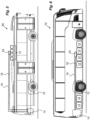
Figs. 5-8 schematically show different vehicles provided with propulsion battery pack cooling systems comprising the distribution pipe circuit with the coolant distribution arrangement. - In this application, "cooling system", "coolant" and "cooling" is used in connection with handling temperatures of propulsion batteries. It is to be understood that even though propulsion batteries produce heat during operation, during certain weather conditions and outside temperatures, the cooling system and the coolant may be used for warming propulsion batteries. The application shall thus not be regarded as limited to only cooling, but may also entail warming. Thus, the temperature of the coolant provided to the propulsion batteries may be cooler than the temperature of the propulsion batteries, but the temperatures of the coolant may also warmer than the temperatures of the propulsion batteries.
- One example of a
distribution pipe circuit 10 of a vehicle propulsionbattery cooling system 8 for coolingpropulsion batteries 12 is shown inFig. 1 . Thedistribution pipe circuit 10 is fluidly connected to amain cooling system 14 that is configured to regulate the temperature of a number of propulsion batteries arranged in a vehicle. The main cooling system comprises a number of units for the temperature regulation such as a temperature conditioning circuit. The temperature conditioning circuit may comprise radiators, pumps, valves, coolers and heaters as well as regulating and control means as well as sensors of different types. This type of temperature conditioning circuit is well known in this technical field and will not be described in more detail. Each propulsion battery comprises a plurality of battery cells encased in enclosure forming a battery pack, which is the wording that is used in this application. It is to be understood that propulsion batteries may have different layout and chemical compositions, which is outside the scope of the present application. The important aspect is that the cells of the battery packs can be temperature controlled. - From the main cooling system only two
conduits coolant inlet circuit 16 for incoming coolant and onecoolant outlet circuit 18 for return coolant. The location may be on the roof of a vehicle such as apublic transport bus 50, seeFig. 5 , i.e. remotely from themain cooling system 14. The battery packs 12 comprise a large number of battery cells encased in a suitable housing, whereby space for coolant is created between the cells and the housing. The coolant is used for keeping the battery cells in an even temperature during operation. The battery packs 12 are connected in appropriate ways to anelectrical machine 15 for propelling the vehicle. The connection to the electrical machine and its controlling does not form part of the present application and will not be discussed in detail in the following. - According to the application, the
inlet conduit 16 is connected to aninlet port 20 of afirst manifold section 22 of acoolant distribution arrangement 24 comprised in thedistribution pipe circuit 10,Fig. 1 . Thefirst manifold section 22 preferably has an elongatedhollow body 26, providing an elongated volume. Theinlet port 20 is preferably positioned at one end of thebody 26, whereby coolant entering the volume will have a flow direction fd along theelongated body 26. The firstcoolant manifold section 22 is further arranged with a number ofoutlet ports 28, the number corresponding to the number of battery packs 12 that are to be cooled, preferably positioned along theelongated body 26.Suitable conduits 30 are connected between theoutlet ports 28 and the battery packs 12. - The
coolant distribution arrangement 24 is further provided with asecond manifold section 32. Thesecond manifold section 32 preferably also has an elongatedhollow body 34, providing an elongated volume. Thesecond manifold section 32 is further provided with a number ofinlet ports 36, the number corresponding to the number of battery packs 12. Suitablefluid conduits 37 are connected between the battery packs 12 and theinlet ports 36. Thesecond manifold section 32 is further provided with anoutlet port 38, preferably positioned at one end of thebody 34, to whichoutlet port 38 thecoolant outlet circuit 18 is connected for return of the coolant to themain cooling system 14. A flow direction fd in theelongated body 34 will be created from theinlet ports 36 to theoutlet port 38. - As seen with this solution, the battery packs 12 are connected in parallel with the first and the
second manifold section first manifold section 22 preferably has a volume that creates an even pressure level from the inlet of coolant. This also creates an even flow to all battery packs which is important for providing the same temperature control in all battery packs of the circuit. - Further, as seen in
Fig. 1 , thefirst manifold section 22 is angled or inclined in its extension in relation to a horizontal plane. Theinlet port 20 is preferably positioned in one end of the first manifold section, and more preferably in the lower end of the inclined first manifold section. This provides the advantage that any air that might be present in the incoming coolant will rise and will move along an upper area of the volume of thefirst manifold section 22 up to the upper end of the inclinedfirst manifold section 22. Further, theoutlet ports 28 to the battery packs 12 are preferably placed in a lower section of the volume of thefirst manifold section 22 in order to avoid or minimize the risk of air entering the battery packs 12 that might be present in the incoming coolant, since most of any air entering the volume of thefirst manifold section 22 will rise to an upper part of the volume. - According to the application, in order to evacuate air that is present in the
first manifold section 22, adeairing outlet port 40 is arranged at the upper end of the inclinedfirst manifold section 22. Thus, thedeairing outlet port 40 is placed downstream of theoutlet ports 28. Thedeairing outlet port 40 is fluidly connected to adeairing inlet port 42 on the second manifold section via aconnection 44, forming a deairing bypass. Thebypass connection 44 could for example be a suitable conduit such as a hose. - Further, as seen in
Fig. 1 , thesecond manifold section 32 is also arranged angled or inclined with respect to a horizontal plane. Here, theoutlet port 38 for the return of coolant is arranged at the upper end of the inclinedsecond manifold 32. Thedeairing inlet port 42 for thebypass connection 44 is positioned upstream of theoutlet port 38 for the coolant as seen in the flow direction fd. Further, thedeairing inlet port 42 for thebypass connection 44 is positioned downstream of theinlet ports 36 of the battery packs 12. Thus, air that is transported from thefirst manifold section 22 to thesecond manifold section 32 via thebypass connection 44 will be introduced into the flow of coolant returning from thesecond manifold section 32 to the main cooling system and evacuated through the expansion tank of the main cooling system. Further, any air present in the coolant from the battery packs 12 will be transported by the flow of coolant returning from thesecond manifold section 32. - Even though the first and the
second manifold sections outlet port 40 of thebypass connection 44 at the top of thefirst manifold section 22 and theoutlet port 38 for coolant return at the top of thesecond manifold section 32. - If more clusters of battery packs 12 are positioned remotely from the main cooling system, an inter-connection may be provided. This may for example be the case with articulated
busses 60 used for public transport,Fig. 7 , where onecluster 12 may be arranged remotely on the roof of the front part while one cluster 12' may be arranged remotely on the roof of the rear part. A first variant of such a solution is schematically shown inFig. 2 where two distribution circuits are connected in series. Here a return circuit 18' from afirst distribution circuit 10 is connected to an inlet port 20' of a first manifold section 22' of a second distribution pipe circuit 10'. The second distribution pipe circuit 10' may be arranged in the same manner as the firstdistribution pipe circuit 10 with fluid conduits 30' from the first manifold section 22' to the battery packs 12' of the second cluster. From the battery packs 12', fluid conduits 37' are connected to the second manifold section 32'. At the upper end of the second manifold section 32', areturn circuit 18 to themain cooling system 14 is provided. As with the previously described embodiment with a single distribution pipe circuit, also here a deairing bypass connection 44' is provided between the first and the second manifold sections 22', 32', whereby air that is transported with the coolant from the firstdistribution pipe circuit 10 will enter the first manifold section 22' of the second distribution pipe circuit 10', and will be led via the bypass connection 44' to the second manifold section 32' of the second distribution pipe circuit 10' and then transported back to the main cooling system with the return coolant as described above. - Another variant is shown in
Fig. 3 , which is very similar regarding the layout as the variant ofFig. 2 . However, here twodistribution circuits 10 and 10' are connected in parallel. Thus, as seen inFig. 3 , theincoming circuit 16 is branched to provide coolant to both firstmanifold sections 22 and 22'. In the same manner, the coolant return from both secondmanifold sections 32 and 32' are connected to thereturn circuit 18. This setup might require an additional pump or a larger pump than for a single circuit or for circuits connected in series. - With this solution, it is thus possible to connect and to cool several battery pack clusters with the same main inlet and outlet conduits from the main cooling system. Thus, even if there are several battery clusters arranged remotely from the cooling system, it is not necessary to provide several inlet and outlet conduits which is an advantage when taking into account the limited space available as well as the distances between the battery pack clusters and the main cooling system.
- In the above shown embodiments, the
coolant distribution arrangement 24 has been shown and described as two separate manifold sections with the bypass connection as a separate conduit, but it is of course possible to provide the coolant distribution arrangement as a single unit.Figure 3 shows a schematic example of such aunit 24". Here a lowerfirst part 22" of theunit 24" corresponds to the first manifold section with theinlet port 20" from the main cooling system at a lower end. Theoutlet ports 28" for supplying coolant to the battery packs are arranged along a lower section of the volume of thefirst part 22". An uppersecond part 32" of theunit 24" corresponds to the second manifold section, having theinlet ports 36" for coolant returning from the battery packs arranged along a lower section of the volume of thesecond part 32". At the upper end of thesecond part 32", anoutlet port 38" for the return of coolant to the main cooling system is provided. As seen in the figure, apassage 44" is provided between the twoparts 22", 32" in an upper area thereof, creating a bypass connection. - Thus, any air entering the volume of the
first part 22" will move along the upper area of the volume of the first part" and will thus not be drawn into the flow of coolant to the battery packs, at least not to any larger extent. Instead, the air will flow through thebypass connection 44" into the volume of thesecond part 32" adjacent theoutlet port 38" for the return of coolant. Thus, the air will be drawn together with the coolant out of the unit and be transported back to the cooling system where it will be deaired via an expansion tank of the cooling system. This solution provides a very compact yet effective solution both for the distribution of coolant to a number of battery packs as well as handling any air included in the coolant without air entering the battery packs. - In the foregoing, it has been mentioned that clusters of battery packs may be arranged on the roof of a vehicle. However, it is possible to utilize the present application where clusters of battery packs are placed in other positions in a vehicle, which positions may be at some distance or remotely from the main cooling system. For instance, in a long-distance bus or
coach 70, some battery packs 12 may be placed under the floor of the passenger compartment towards the front of the coach, where themain cooling system 14 is situated in the rear of the coach as seen inFig. 6 . Also with this situation, it is an advantage that as few conduits as possible are drawn through the vehicle, since it will interfere with luggage space under the passenger compartment and also lead to increased assembly time of the system as well as increased complexity. As mentioned above, with the solution according to the present application, only two conduits are needed for the supply of coolant to battery packs positioned remotely from the main cooling system. - Another example where the present solution may be used is for
trucks 80 and the like heavy vehicles that are configured to be connected to and tow atrailer 82. The trailer is often a separate unit that may be connected and disconnected to the truck. As seen schematically inFig. 8 , one or severalbattery pack clusters 12 may be provided remotely on the trailer in addition to battery packs mounted on the truck. The present application may then be used for cooling of the battery packs on the trailer, and it is therefore an advantage that only two conduits are arranged between the truck and the trailer. - It is to be understood that the embodiments described above and shown in the drawings are to be regarded only as non-limiting examples and that the present application can be modified in many ways within the scope of the patent claims.
Claims (15)
- A coolant distribution arrangement (24, 24', 24") for a vehicle propulsion battery cooling system (8), the cooling system (8) comprising a coolant inlet circuit (16), a coolant outlet circuit (18), and at least one coolant branch (30, 37), configured to cool a set of propulsion battery packs (12, 12'), wherein- the arrangement (24, 24', 24") comprises a first manifold section (22, 22', 22"), which first manifold section (22, 22', 22") comprises:- a coolant inlet (20, 20', 20") configured to receive coolant from the coolant inlet circuit (16),- supply outlets (28, 28', 28") configured to supply coolant to the at least one coolant branch (30, 37; 30', 37'),wherein the arrangement comprises a second manifold section (32, 32', 32"), which second manifold section (32, 32', 32") comprises:- receiving inlets (36, 36', 36") configured to receive coolant from the at least one coolant branch (30, 37; 30', 37'),- a coolant outlet (38, 38', 38") configured to return coolant to the coolant outlet circuit (18), andwherein the arrangement (24, 24', 24") comprises a deairing connection (44, 44', 44") between the first manifold section (22, 22', 22") and the second manifold section (32, 32', 32") configured to evacuate air from the first manifold section (22, 22', 22") to the second manifold section (32, 32', 32").
- A coolant distribution arrangement (24, 24', 24") according to claim 1, wherein the deairing connection (44, 44', 44") is arranged downstream of the supply outlets (28, 28', 28") of the first manifold section (22, 22', 22").
- A coolant distribution arrangement (24, 24', 24") according to claim 2, wherein the deairing connection (44, 44', 44"), when the arrangement (24, 24', 24") is attached to a vehicle, is positioned higher than the supply outlets (28, 28', 28").
- A coolant distribution arrangement (24, 24', 24") according to claim 2 or 3, wherein the coolant inlet (20, 20', 20") is arranged upstream of said supply outlets (28, 28', 28").
- A coolant distribution arrangement (24, 24', 24") according to any of the claims 2 to 4, wherein the deairing connection (44, 44', 44") is arranged downstream of the receiving inlets (26, 26', 26") of the second manifold section (32, 32', 32").
- A coolant distribution arrangement (24, 24', 24") according to claim 5, wherein the deairing connection (44, 44', 44") is arranged upstream of the coolant outlet (28, 28', 28"), whereby air in the second manifold section (32, 32', 32") is evacuated through the coolant outlet (28, 28', 28").
- A coolant distribution arrangement (24, 24', 24") according to any of the claims 4 to 6, wherein the coolant outlet (28, 28', 28"), when the arrangement (24, 24', 24") is attached to a vehicle, is positioned higher than the deairing connection (44, 44', 44").
- A coolant distribution arrangement (24, 24') according to any of the preceding claims, wherein the first and the second manifold sections (22, 22', 32, 32') are discrete components and wherein the deairing connection (44, 44') comprises a separate conduit.
- A coolant distribution arrangement (24") according to any of the preceding claims, wherein the first and the second manifold sections (22", 32") form a single unit (24") and wherein the deairing connection comprises a passage (44") provided in the unit (24").
- A vehicle propulsion battery cooling system (8) comprising:- at least one distribution pipe circuit (10, 10') fluidly connected to a main cooling system (14),- at least one coolant branch (30, 37; 30', 37') configured to cool a set of propulsion battery packs, and- a coolant distribution arrangement (24, 24', 24") according to any of the preceding claims.
- A vehicle propulsion battery cooling system (8) according to claim 10, comprising several distribution pipe circuits (10, 10') fluidly connected in series to the main cooling system (14).
- A vehicle propulsion battery cooling system (8) according to claim 10, comprising several distribution pipe circuits (10, 10') fluidly connected in parallel to the main cooling system (14).
- A vehicle propulsion battery cooling system (8) according to claims 10 to12, wherein the at least one distribution pipe circuit (10, 10') and the battery packs (12, 12') are located remotely from the main cooling system.
- A vehicle propulsion battery cooling system (8) according to claim 12, comprising a single coolant inlet circuit (16) and a single coolant outlet circuit (18) for fluid connection between the main cooling system (14) and the at least one distribution pipe circuit (10. 10').
- A vehicle comprising a main cooling system, a set of propulsion battery packs (12, 12') and a vehicle propulsion battery cooling system (8) according to any of the claims 10 - 14, wherein the vehicle propulsion battery cooling system (8) is configured to cool the set of propulsion battery packs (12, 12').
Priority Applications (1)
| Application Number | Priority Date | Filing Date | Title |
|---|---|---|---|
| EP22175277.7A EP4283760B1 (en) | 2022-05-25 | 2022-05-25 | Coolant distribution arrangement and system for cooling vehicle propulsion batteries |
Applications Claiming Priority (1)
| Application Number | Priority Date | Filing Date | Title |
|---|---|---|---|
| EP22175277.7A EP4283760B1 (en) | 2022-05-25 | 2022-05-25 | Coolant distribution arrangement and system for cooling vehicle propulsion batteries |
Publications (2)
| Publication Number | Publication Date |
|---|---|
| EP4283760A1 true EP4283760A1 (en) | 2023-11-29 |
| EP4283760B1 EP4283760B1 (en) | 2025-07-30 |
Family
ID=82361412
Family Applications (1)
| Application Number | Title | Priority Date | Filing Date |
|---|---|---|---|
| EP22175277.7A Active EP4283760B1 (en) | 2022-05-25 | 2022-05-25 | Coolant distribution arrangement and system for cooling vehicle propulsion batteries |
Country Status (1)
| Country | Link |
|---|---|
| EP (1) | EP4283760B1 (en) |
Citations (5)
| Publication number | Priority date | Publication date | Assignee | Title |
|---|---|---|---|---|
| WO2020192807A1 (en) * | 2019-03-27 | 2020-10-01 | Novacek Tomas | Heat exchanger with double manifold |
| WO2021188030A1 (en) * | 2020-03-17 | 2021-09-23 | Scania Cv Ab | Coolant distribution manifold, propulsion battery cooling system, and vehicle |
| WO2021221550A1 (en) * | 2020-04-29 | 2021-11-04 | Scania Cv Ab | Thermal management system, and vehicle |
| EP3916209A1 (en) * | 2020-05-28 | 2021-12-01 | Volkswagen Ag | Hybrid vehicle with a cooling system |
| WO2022005373A1 (en) * | 2020-07-01 | 2022-01-06 | Scania Cv Ab | Multiple circuit thermal management system comprising mixing lines, and vehicle |
-
2022
- 2022-05-25 EP EP22175277.7A patent/EP4283760B1/en active Active
Patent Citations (5)
| Publication number | Priority date | Publication date | Assignee | Title |
|---|---|---|---|---|
| WO2020192807A1 (en) * | 2019-03-27 | 2020-10-01 | Novacek Tomas | Heat exchanger with double manifold |
| WO2021188030A1 (en) * | 2020-03-17 | 2021-09-23 | Scania Cv Ab | Coolant distribution manifold, propulsion battery cooling system, and vehicle |
| WO2021221550A1 (en) * | 2020-04-29 | 2021-11-04 | Scania Cv Ab | Thermal management system, and vehicle |
| EP3916209A1 (en) * | 2020-05-28 | 2021-12-01 | Volkswagen Ag | Hybrid vehicle with a cooling system |
| WO2022005373A1 (en) * | 2020-07-01 | 2022-01-06 | Scania Cv Ab | Multiple circuit thermal management system comprising mixing lines, and vehicle |
Also Published As
| Publication number | Publication date |
|---|---|
| EP4283760B1 (en) | 2025-07-30 |
Similar Documents
| Publication | Publication Date | Title |
|---|---|---|
| US11001123B2 (en) | Thermal management unit and system | |
| US10476117B2 (en) | Vehicle power supply system | |
| US11207947B2 (en) | Cooling system for a motor vehicle and motor vehicle having such a cooling system | |
| US20220377946A1 (en) | Integration Component, Temperature-Control System, and Motor Vehicle | |
| CN115698477B (en) | Multi-circuit thermal management system including hybrid pipeline and vehicle | |
| JP2018069808A (en) | vehicle | |
| EP4143423B1 (en) | Thermal management system, and vehicle | |
| US10866037B2 (en) | Process valve manifold and heat exchanger system | |
| CN115104215B (en) | Coolant distribution manifold, propulsion battery cooling system and vehicle | |
| CN111788082B (en) | Thermal regulation systems for electrically driven vehicles and vehicles including such systems | |
| WO2022234269A1 (en) | A heating and cooling system for a vehicle | |
| CN112895843B (en) | Thermal management system for a motor vehicle and motor vehicle having such a thermal management system | |
| EP4283760B1 (en) | Coolant distribution arrangement and system for cooling vehicle propulsion batteries | |
| CN120018957A (en) | Thermal management system and vehicle having at least one such thermal management system | |
| US20250125446A1 (en) | Air cooling system for an electric vehicle | |
| CA2707645C (en) | Heating/cooling system having a plurality of separate consumer circuits, particularly for commercial vehicles | |
| WO2021205973A1 (en) | Cooling circuit with several cooling temperatures for motor vehicle and method for operating such cooling circuit | |
| CN112572093A (en) | Thermal management system and engineering machinery | |
| US20250121647A1 (en) | Air cooling system for an electric vehicle | |
| CN117818431A (en) | A fuel cell vehicle thermal management integrated system and vehicle | |
| CN122008783A (en) | Thermal management system of vehicle and vehicle | |
| CN117901614A (en) | Arrangement method of thermal management module, thermal management module and whole vehicle thermal management system | |
| CN114335807A (en) | Battery cooling system of electric mining dump truck and control method |
Legal Events
| Date | Code | Title | Description |
|---|---|---|---|
| PUAI | Public reference made under article 153(3) epc to a published international application that has entered the european phase |
Free format text: ORIGINAL CODE: 0009012 |
|
| STAA | Information on the status of an ep patent application or granted ep patent |
Free format text: STATUS: THE APPLICATION HAS BEEN PUBLISHED |
|
| AK | Designated contracting states |
Kind code of ref document: A1 Designated state(s): AL AT BE BG CH CY CZ DE DK EE ES FI FR GB GR HR HU IE IS IT LI LT LU LV MC MK MT NL NO PL PT RO RS SE SI SK SM TR |
|
| STAA | Information on the status of an ep patent application or granted ep patent |
Free format text: STATUS: REQUEST FOR EXAMINATION WAS MADE |
|
| 17P | Request for examination filed |
Effective date: 20240529 |
|
| RBV | Designated contracting states (corrected) |
Designated state(s): AL AT BE BG CH CY CZ DE DK EE ES FI FR GB GR HR HU IE IS IT LI LT LU LV MC MK MT NL NO PL PT RO RS SE SI SK SM TR |
|
| GRAP | Despatch of communication of intention to grant a patent |
Free format text: ORIGINAL CODE: EPIDOSNIGR1 |
|
| STAA | Information on the status of an ep patent application or granted ep patent |
Free format text: STATUS: GRANT OF PATENT IS INTENDED |
|
| RIC1 | Information provided on ipc code assigned before grant |
Ipc: H01M 50/249 20210101ALI20250321BHEP Ipc: H01M 10/663 20140101ALI20250321BHEP Ipc: H01M 10/6567 20140101ALI20250321BHEP Ipc: H01M 10/6556 20140101ALI20250321BHEP Ipc: B60K 1/04 20190101ALI20250321BHEP Ipc: B60K 1/00 20060101ALI20250321BHEP Ipc: B60K 11/02 20060101ALI20250321BHEP Ipc: H01M 10/613 20140101AFI20250321BHEP |
|
| INTG | Intention to grant announced |
Effective date: 20250414 |
|
| GRAS | Grant fee paid |
Free format text: ORIGINAL CODE: EPIDOSNIGR3 |
|
| GRAA | (expected) grant |
Free format text: ORIGINAL CODE: 0009210 |
|
| STAA | Information on the status of an ep patent application or granted ep patent |
Free format text: STATUS: THE PATENT HAS BEEN GRANTED |
|
| AK | Designated contracting states |
Kind code of ref document: B1 Designated state(s): AL AT BE BG CH CY CZ DE DK EE ES FI FR GB GR HR HU IE IS IT LI LT LU LV MC MK MT NL NO PL PT RO RS SE SI SK SM TR |
|
| REG | Reference to a national code |
Ref country code: GB Ref legal event code: FG4D |
|
| REG | Reference to a national code |
Ref country code: CH Ref legal event code: EP |
|
| REG | Reference to a national code |
Ref country code: DE Ref legal event code: R096 Ref document number: 602022018304 Country of ref document: DE |
|
| REG | Reference to a national code |
Ref country code: IE Ref legal event code: FG4D |
|
| REG | Reference to a national code |
Ref country code: SE Ref legal event code: TRGR |
|
| REG | Reference to a national code |
Ref country code: NL Ref legal event code: MP Effective date: 20250730 |
|
| REG | Reference to a national code |
Ref country code: AT Ref legal event code: MK05 Ref document number: 1820056 Country of ref document: AT Kind code of ref document: T Effective date: 20250730 |
|
| PG25 | Lapsed in a contracting state [announced via postgrant information from national office to epo] |
Ref country code: PT Free format text: LAPSE BECAUSE OF FAILURE TO SUBMIT A TRANSLATION OF THE DESCRIPTION OR TO PAY THE FEE WITHIN THE PRESCRIBED TIME-LIMIT Effective date: 20251202 |
|
| PG25 | Lapsed in a contracting state [announced via postgrant information from national office to epo] |
Ref country code: IS Free format text: LAPSE BECAUSE OF FAILURE TO SUBMIT A TRANSLATION OF THE DESCRIPTION OR TO PAY THE FEE WITHIN THE PRESCRIBED TIME-LIMIT Effective date: 20251130 |
|
| PG25 | Lapsed in a contracting state [announced via postgrant information from national office to epo] |
Ref country code: NO Free format text: LAPSE BECAUSE OF FAILURE TO SUBMIT A TRANSLATION OF THE DESCRIPTION OR TO PAY THE FEE WITHIN THE PRESCRIBED TIME-LIMIT Effective date: 20251030 |
|
| REG | Reference to a national code |
Ref country code: LT Ref legal event code: MG9D |
|
| PG25 | Lapsed in a contracting state [announced via postgrant information from national office to epo] |
Ref country code: AT Free format text: LAPSE BECAUSE OF FAILURE TO SUBMIT A TRANSLATION OF THE DESCRIPTION OR TO PAY THE FEE WITHIN THE PRESCRIBED TIME-LIMIT Effective date: 20250730 |
|
| P01 | Opt-out of the competence of the unified patent court (upc) registered |
Free format text: CASE NUMBER: UPC_APP_0016371_4283760/2025 Effective date: 20251209 |
|
| PG25 | Lapsed in a contracting state [announced via postgrant information from national office to epo] |
Ref country code: FI Free format text: LAPSE BECAUSE OF FAILURE TO SUBMIT A TRANSLATION OF THE DESCRIPTION OR TO PAY THE FEE WITHIN THE PRESCRIBED TIME-LIMIT Effective date: 20250730 |
|
| PG25 | Lapsed in a contracting state [announced via postgrant information from national office to epo] |
Ref country code: HR Free format text: LAPSE BECAUSE OF FAILURE TO SUBMIT A TRANSLATION OF THE DESCRIPTION OR TO PAY THE FEE WITHIN THE PRESCRIBED TIME-LIMIT Effective date: 20250730 Ref country code: NL Free format text: LAPSE BECAUSE OF FAILURE TO SUBMIT A TRANSLATION OF THE DESCRIPTION OR TO PAY THE FEE WITHIN THE PRESCRIBED TIME-LIMIT Effective date: 20250730 |
|
| PG25 | Lapsed in a contracting state [announced via postgrant information from national office to epo] |
Ref country code: GR Free format text: LAPSE BECAUSE OF FAILURE TO SUBMIT A TRANSLATION OF THE DESCRIPTION OR TO PAY THE FEE WITHIN THE PRESCRIBED TIME-LIMIT Effective date: 20251031 |
|
| PG25 | Lapsed in a contracting state [announced via postgrant information from national office to epo] |
Ref country code: LV Free format text: LAPSE BECAUSE OF FAILURE TO SUBMIT A TRANSLATION OF THE DESCRIPTION OR TO PAY THE FEE WITHIN THE PRESCRIBED TIME-LIMIT Effective date: 20250730 |
|
| PG25 | Lapsed in a contracting state [announced via postgrant information from national office to epo] |
Ref country code: PL Free format text: LAPSE BECAUSE OF FAILURE TO SUBMIT A TRANSLATION OF THE DESCRIPTION OR TO PAY THE FEE WITHIN THE PRESCRIBED TIME-LIMIT Effective date: 20250730 Ref country code: BG Free format text: LAPSE BECAUSE OF FAILURE TO SUBMIT A TRANSLATION OF THE DESCRIPTION OR TO PAY THE FEE WITHIN THE PRESCRIBED TIME-LIMIT Effective date: 20250730 |
|
| PG25 | Lapsed in a contracting state [announced via postgrant information from national office to epo] |
Ref country code: RS Free format text: LAPSE BECAUSE OF FAILURE TO SUBMIT A TRANSLATION OF THE DESCRIPTION OR TO PAY THE FEE WITHIN THE PRESCRIBED TIME-LIMIT Effective date: 20251030 |
|
| PG25 | Lapsed in a contracting state [announced via postgrant information from national office to epo] |
Ref country code: ES Free format text: LAPSE BECAUSE OF FAILURE TO SUBMIT A TRANSLATION OF THE DESCRIPTION OR TO PAY THE FEE WITHIN THE PRESCRIBED TIME-LIMIT Effective date: 20250730 |
|
| PG25 | Lapsed in a contracting state [announced via postgrant information from national office to epo] |
Ref country code: SM Free format text: LAPSE BECAUSE OF FAILURE TO SUBMIT A TRANSLATION OF THE DESCRIPTION OR TO PAY THE FEE WITHIN THE PRESCRIBED TIME-LIMIT Effective date: 20250730 |
|
| PG25 | Lapsed in a contracting state [announced via postgrant information from national office to epo] |
Ref country code: DK Free format text: LAPSE BECAUSE OF FAILURE TO SUBMIT A TRANSLATION OF THE DESCRIPTION OR TO PAY THE FEE WITHIN THE PRESCRIBED TIME-LIMIT Effective date: 20250730 |
|
| PG25 | Lapsed in a contracting state [announced via postgrant information from national office to epo] |
Ref country code: IT Free format text: LAPSE BECAUSE OF FAILURE TO SUBMIT A TRANSLATION OF THE DESCRIPTION OR TO PAY THE FEE WITHIN THE PRESCRIBED TIME-LIMIT Effective date: 20250730 |
|
| PG25 | Lapsed in a contracting state [announced via postgrant information from national office to epo] |
Ref country code: CZ Free format text: LAPSE BECAUSE OF FAILURE TO SUBMIT A TRANSLATION OF THE DESCRIPTION OR TO PAY THE FEE WITHIN THE PRESCRIBED TIME-LIMIT Effective date: 20250730 |
|
| PG25 | Lapsed in a contracting state [announced via postgrant information from national office to epo] |
Ref country code: EE Free format text: LAPSE BECAUSE OF FAILURE TO SUBMIT A TRANSLATION OF THE DESCRIPTION OR TO PAY THE FEE WITHIN THE PRESCRIBED TIME-LIMIT Effective date: 20250730 Ref country code: SK Free format text: LAPSE BECAUSE OF FAILURE TO SUBMIT A TRANSLATION OF THE DESCRIPTION OR TO PAY THE FEE WITHIN THE PRESCRIBED TIME-LIMIT Effective date: 20250730 |