EP4283644A1 - Electric tool - Google Patents
Electric tool Download PDFInfo
- Publication number
- EP4283644A1 EP4283644A1 EP22773911.7A EP22773911A EP4283644A1 EP 4283644 A1 EP4283644 A1 EP 4283644A1 EP 22773911 A EP22773911 A EP 22773911A EP 4283644 A1 EP4283644 A1 EP 4283644A1
- Authority
- EP
- European Patent Office
- Prior art keywords
- contact rod
- pressing block
- power tool
- switch
- straight line
- Prior art date
- Legal status (The legal status is an assumption and is not a legal conclusion. Google has not performed a legal analysis and makes no representation as to the accuracy of the status listed.)
- Granted
Links
Images





Classifications
-
- H—ELECTRICITY
- H01—ELECTRIC ELEMENTS
- H01H—ELECTRIC SWITCHES; RELAYS; SELECTORS; EMERGENCY PROTECTIVE DEVICES
- H01H9/00—Details of switching devices, not covered by groups H01H1/00 - H01H7/00
- H01H9/02—Bases, casings, or covers
- H01H9/06—Casing of switch constituted by a handle serving a purpose other than the actuation of the switch, e.g. by the handle of a vacuum cleaner
-
- H—ELECTRICITY
- H01—ELECTRIC ELEMENTS
- H01H—ELECTRIC SWITCHES; RELAYS; SELECTORS; EMERGENCY PROTECTIVE DEVICES
- H01H3/00—Mechanisms for operating contacts
- H01H3/32—Driving mechanisms, i.e. for transmitting driving force to the contacts
- H01H3/46—Driving mechanisms, i.e. for transmitting driving force to the contacts using rod or lever linkage, e.g. toggle
-
- B—PERFORMING OPERATIONS; TRANSPORTING
- B25—HAND TOOLS; PORTABLE POWER-DRIVEN TOOLS; MANIPULATORS
- B25F—COMBINATION OR MULTI-PURPOSE TOOLS NOT OTHERWISE PROVIDED FOR; DETAILS OR COMPONENTS OF PORTABLE POWER-DRIVEN TOOLS NOT PARTICULARLY RELATED TO THE OPERATIONS PERFORMED AND NOT OTHERWISE PROVIDED FOR
- B25F5/00—Details or components of portable power-driven tools not particularly related to the operations performed and not otherwise provided for
- B25F5/02—Construction of casings, bodies or handles
-
- H—ELECTRICITY
- H01—ELECTRIC ELEMENTS
- H01H—ELECTRIC SWITCHES; RELAYS; SELECTORS; EMERGENCY PROTECTIVE DEVICES
- H01H1/00—Contacts
- H01H1/12—Contacts characterised by the manner in which co-operating contacts engage
- H01H1/14—Contacts characterised by the manner in which co-operating contacts engage by abutting
- H01H1/24—Contacts characterised by the manner in which co-operating contacts engage by abutting with resilient mounting
-
- H—ELECTRICITY
- H01—ELECTRIC ELEMENTS
- H01H—ELECTRIC SWITCHES; RELAYS; SELECTORS; EMERGENCY PROTECTIVE DEVICES
- H01H13/00—Switches having rectilinearly-movable operating part or parts adapted for pushing or pulling in one direction only, e.g. push-button switch
- H01H13/02—Details
- H01H13/04—Cases; Covers
- H01H13/08—Casing of switch constituted by a handle serving a purpose other than the actuation of the switch
-
- H—ELECTRICITY
- H01—ELECTRIC ELEMENTS
- H01H—ELECTRIC SWITCHES; RELAYS; SELECTORS; EMERGENCY PROTECTIVE DEVICES
- H01H13/00—Switches having rectilinearly-movable operating part or parts adapted for pushing or pulling in one direction only, e.g. push-button switch
- H01H13/02—Details
- H01H13/12—Movable parts; Contacts mounted thereon
- H01H13/20—Driving mechanisms
-
- H—ELECTRICITY
- H01—ELECTRIC ELEMENTS
- H01H—ELECTRIC SWITCHES; RELAYS; SELECTORS; EMERGENCY PROTECTIVE DEVICES
- H01H13/00—Switches having rectilinearly-movable operating part or parts adapted for pushing or pulling in one direction only, e.g. push-button switch
- H01H13/50—Switches having rectilinearly-movable operating part or parts adapted for pushing or pulling in one direction only, e.g. push-button switch having a single operating member
- H01H13/56—Switches having rectilinearly-movable operating part or parts adapted for pushing or pulling in one direction only, e.g. push-button switch having a single operating member the contact returning to its original state upon the next application of operating force
- H01H13/58—Switches having rectilinearly-movable operating part or parts adapted for pushing or pulling in one direction only, e.g. push-button switch having a single operating member the contact returning to its original state upon the next application of operating force with contact-driving member rotated step-wise in one direction
- H01H13/585—Switches having rectilinearly-movable operating part or parts adapted for pushing or pulling in one direction only, e.g. push-button switch having a single operating member the contact returning to its original state upon the next application of operating force with contact-driving member rotated step-wise in one direction wherein the movable contact rotates around the axis of the push button
-
- H—ELECTRICITY
- H01—ELECTRIC ELEMENTS
- H01H—ELECTRIC SWITCHES; RELAYS; SELECTORS; EMERGENCY PROTECTIVE DEVICES
- H01H71/00—Details of the protective switches or relays covered by groups H01H73/00 - H01H83/00
- H01H71/10—Operating or release mechanisms
- H01H71/66—Power reset mechanisms
-
- H—ELECTRICITY
- H01—ELECTRIC ELEMENTS
- H01H—ELECTRIC SWITCHES; RELAYS; SELECTORS; EMERGENCY PROTECTIVE DEVICES
- H01H71/00—Details of the protective switches or relays covered by groups H01H73/00 - H01H83/00
- H01H71/10—Operating or release mechanisms
- H01H71/66—Power reset mechanisms
- H01H2071/665—Power reset mechanisms the reset mechanism operating directly on the normal manual operator, e.g. electromagnet pushes manual release lever back into "ON" position
-
- H—ELECTRICITY
- H01—ELECTRIC ELEMENTS
- H01H—ELECTRIC SWITCHES; RELAYS; SELECTORS; EMERGENCY PROTECTIVE DEVICES
- H01H3/00—Mechanisms for operating contacts
- H01H3/32—Driving mechanisms, i.e. for transmitting driving force to the contacts
- H01H3/38—Driving mechanisms, i.e. for transmitting driving force to the contacts using spring or other flexible shaft coupling
-
- H—ELECTRICITY
- H01—ELECTRIC ELEMENTS
- H01H—ELECTRIC SWITCHES; RELAYS; SELECTORS; EMERGENCY PROTECTIVE DEVICES
- H01H9/00—Details of switching devices, not covered by groups H01H1/00 - H01H7/00
- H01H9/02—Bases, casings, or covers
- H01H9/04—Dustproof, splashproof, drip-proof, waterproof, or flameproof casings
Definitions
- the present application relates to a power tool.
- a power tool with a microswitch is safer and less expensive.
- the relatively short turn-on stroke of the microswitch is not applicable to a working condition of the power tool and a user's usage habits.
- the switch is easily turned off by vibrations generated when the power tool runs. If the stroke of a trigger coincides with the stroke of the microswitch, it is inconvenient for the user to accurately manipulate the power tool. In this case, the feel of using an operating element is poor.
- the structure of the microswitch is easily damaged, resulting in a relatively short life of the microswitch.
- the present application provides a power tool.
- the power tool is provided with a switch, and an operating element controlling the switch to be turned on has a good operation feel and is safe and reliable.
- an impact force to which the switch is subjected is buffered by a pressing block so that the switch is protected, thereby prolonging the service life of the switch.
- the operating element has a simple and reliable overall structure.
- the present application provides a power tool.
- the power tool includes: a housing; an electric motor disposed in the housing; a switch including a trigger point for controlling the electric motor to be turned on; an operating element to be operated to trigger the switch; a contact rod connected to the operating element, where the operating element is capable of pushing the contact rod to move along a straight line; a pressing block elastically connected to the contact rod and capable of being driven by the contact rod to push the trigger point; and a reset element connected to the contact rod.
- the operating element is capable of pushing the contact rod to move along the straight line.
- a mounting cavity is formed in the contact rod, and the pressing block is disposed in the mounting cavity; and the power tool further includes a biasing element disposed in the mounting cavity, connecting the contact rod to the pressing block, and causing the contact rod and the pressing block to move at different speeds.
- the electric motor includes an electric motor shaft extending along a first axis
- the operating element is a push button capable of being pushed along a first straight line, where the first straight line is substantially parallel to the first axis.
- the electric motor includes an electric motor shaft extending along a first axis
- the operating element is rotatably connected to the housing
- the contact rod and the pressing block are capable of being driven by the operating element to move along a first straight line and are capable of being reset by the reset element, where the first straight line is a radial direction of the first axis.
- the first straight line passes through the switch, and the trigger point is capable of being pushed in a direction parallel to the first straight line so that the electric motor is turned on.
- At least one second straight line perpendicular to the first straight line exists, where a projection of the switch in the direction of the second straight line at least partially overlaps a projection of the contact rod in the direction of the second straight line.
- the power tool further includes a contact piece abutting against the pressing block, where when the contact rod moves along the first straight line, the contact piece is capable of being driven by the pressing block to rotate so as to trigger the switch.
- the power tool further includes a switch box, where at least part of the switch, the contact rod, and the reset element are disposed in the switch box, and the contact rod includes an exposed portion exposed from the switch box.
- the power tool further includes a dust-proof member surrounding at least part of the exposed portion of the contact rod, where the exposed portion of the contact rod is in contact with the operating element.
- the volume of the switch box is greater than or equal to 5000 cubic millimeters and less than or equal to 9500 cubic millimeters.
- a power tool includes: a housing; an electric motor disposed in the housing; a switch including a trigger point for controlling the switch to be turned on; and an operating element to be operated to trigger the switch.
- the power tool further includes: a contact rod capable of abutting against the operating element to be pushed; a pressing block disposed between the contact rod and the trigger point, where the contact rod forms a mounting cavity, and the pressing block is at least partially disposed in the mounting cavity; a biasing element connecting the pressing block to the contact rod; and a switch box supporting the pressing block, the switch, the biasing element, and the contact rod.
- the operating element is capable of pushing the contact rod to move along a straight line from a first stage to a second stage.
- the pressing block is separated from the trigger point when the contact rod is in the first stage, the trigger point is pressed and triggered by the pressing block when the contact rod is in the second stage, and the ratio of the stroke of the contact rod in the first stage to the stroke of the contact rod in the second stage is higher than or equal to 1 and lower than or equal to 1.5.
- the biasing element compresses the stroke of the contact rod and transmits the stroke of the contact rod to the pressing block, and the biasing element is disposed in the mounting cavity.
- the power tool includes a reset element connected to the contact rod, where the contact rod compresses the reset element when the contact rod moves in a first stage.
- the contact rod and the pressing block are capable of being driven by the operating element to move along a first straight line and are capable of being reset by the reset element.
- the contact rod includes connecting holes
- the pressing block is provided with a connecting pin, where the connecting pin is placed into the connecting holes so that the contact rod and the pressing block are connected to each other and are movable relative to each other in the direction of the first straight line.
- the contact rod includes a mounting slot
- the pressing block is provided with an adapter
- the adapter is placed into the mounting slot so that the pressing block is positioned and the pressing block and the contact rod are movable relative to each other in the direction of the first straight line.
- the reset element is disposed in the switch box.
- the ratio of the elastic force of the biasing element to the elastic force of the trigger point is higher than or equal to 2 and lower than or equal to 3 when the contact rod is in the second stage.
- the stroke range of the operating element is greater than or equal to 4 mm and less than or equal to 6 mm.
- the contact rod and the pressing block are configured to connect the operating element to the switch such that the turn-on stroke of the operating element is increased, thereby improving the feel and safety of using the operating element, an impact force to which the switch is subjected is buffered by the pressing block so that the switch is protected, thereby prolonging the service life of the switch, and the operating element has a simple and reliable overall structure.
- the present application provides a power tool 100, where the power tool 100 may be a tool which needs to be controlled by a switch to be turned on, for example, an angle grinder, an electric drill, an electric hammer, or a polisher.
- the power tool 100 includes a housing 110, an electric motor 120, and a working assembly, where the electric motor 120 drives the working assembly to run.
- the angle grinder is used as an example for describing the specific structure of the power tool 100.
- the work assembly includes an output shaft and a working accessory, where the working accessory may be a grinding disc or the like, and the electric motor 120 drives, through the output shaft, the working accessory to rotate to perform a polishing operation.
- the power tool 100 further includes a switch 130, the electric motor 120 is disposed in the housing 110, and the switch 130 can control the electric motor 120 to be turned on and off.
- the switch 130 may be a switch with a relatively short stroke such as a microswitch or a membrane switch so that a cost can be reduced and the volume of the whole power tool can be reduced.
- the switch 130 may be triggered by a small force.
- the power tool 100 further includes an operating element 140 for a user to operate. The user presses the operating element 140 to trigger the switch 130 so as to turn on the electric motor 120.
- the power tool 100 further includes a contact rod 150 and a pressing block 160, the contact rod 150 is connected to the operating element 140, and the operating element 140 can push the contact rod 150 to move along a straight line from a first stage to a second stage.
- the contact rod 150 is supported directly or indirectly by the housing 110, and the contact rod can be in contact with the operating element 140.
- the pressing block 160 is disposed between the contact rod 150 and the switch 130, and the contact rod 150 drives the pressing block 160 to be in contact with the switch 130 and press a trigger point 131 to trigger the switch 130.
- the pressing block 160 is separated from the trigger point 131 when the contact rod 150 is in the first stage, and the trigger point 131 of the switch is pressed and triggered by the pressing block 160 when the contact rod 150 is in the second stage.
- the operating element 140 drives the contact rod 150 to enter the first stage from an initial position and move, and the contact rod 150 drives the pressing block 160 to move toward the trigger point 131.
- the movement of the operating element 140 is an idle stroke. Even though the user presses the operating element 140, the contact rod 150 in the first stage cannot drive the pressing block 160 to be in contact with the switch 130, and the switch 130 is not triggered in this case.
- the operating element 140 continues pushing the contact rod 150 such that the contact rod 150 enters the second stage, and the contact rod 150 drives the pressing block 160 to be in contact with the trigger point 131.
- the pressing block 160 is pushed to press the trigger point 131 such that the switch 130 is triggered and the electric motor 120 is turned on.
- the contact rod 150 enters an end position when the operating element 140 is pushed to the end of the stroke.
- the ratio of the stroke of the contact rod 150 in the first stage to the stroke of the contact rod 150 in the second stage is higher than or equal to 1 and lower than or equal to 1.5.
- the problem that the switch 130 is easy to trigger can be solved through the configuration of the contact rod 150 in the first stage.
- the power tool 100 does not start the electric motor 120 by mistake because of a vibration and a false trigger of the user, and the power tool 100 is prevented from suddenly running and hurting the user.
- the power tool 100 further includes a reset element 170 connected to the contact rod 150.
- the reset element 170 is disposed between the switch 130 and the contact rod 150, and the reset element 170 is not in contact with the trigger point 131.
- the reset element 170 is an elastic member, which may be a spring, a compression spring, a tension spring, a torsion spring, a spiral spring, a rubber ring, a steel wire, an airbag, or the like.
- the contact rod 150 compresses the reset element 170.
- the reset element 170 absorbs a pressure supplied to the operating element 140 by the user so that the user can be effectively prevented from triggering the operating element 140 by mistake to start the electric motor 120 and the safety of the power tool 100 is improved.
- the switch 130 is pressed by the pressing block 160, and the contact rod 150 is located in the middle of the initial position and the end position or at the end position.
- the operating element 140 is released. In this case, the reset element 170 releases the contact rod 150 and pushes the contact rod 150 to return to the initial position such that the contact rod 150 and the pressing block 160 are reset.
- the power tool 100 further includes a biasing element 180 connecting the contact rod 150 to the pressing block 160, compressing the stroke of the contact rod 150, and then transmitting the stroke of the contact rod 150 to the pressing block 160.
- the biasing element 180 is also the elastic member, which may be the spring, the compression spring, the tension spring, the torsion spring, the spiral spring, the rubber ring, the steel wire, the airbag, or the like.
- the biasing element 180 is disposed between the pressing block 160 and the contact rod 150. After the contact rod 150 enters the second stage, the pressing block 160 is in contact with the trigger point 131 of the switch 130, and the user continues pressing the operating element 140 so that the contact rod 150 continues moving toward the switch 130.
- the contact rod 150 approaches the switch 130, and the pressing block 160 and the biasing element 180 between the switch 130 and the contact rod 150 are squeezed so that the biasing element 180 is compressed and pushes the pressing block 160 to press the trigger point 131 at the same time.
- the biasing element 180 is provided so that the stroke transmitted to the pressing block 160 by the contact rod 150 can be compressed.
- the biasing element 180 can be used for buffering a pressing force of the user to the operating element 140 so that the reliability of an operating assembly 200 integrally constituted by the contact rod 150, the operating element 140, the pressing block 160, and the switch 130 is improved.
- the biasing element 180 can be used for buffering the pressing force of the user to the operating element 140 so that the switch 130 is effectively protected and the service life of the switch 130 is prolonged.
- the biasing element 180 provides an elastic force for the pressing block 160 so that it is ensured that the switch 130 is prevented from being reset due to vibrations during the working of the power tool 100 and causing an abnormal shutdown.
- a mounting cavity 151 is formed in the middle portion of the contact rod 150, and the biasing element 180 and the pressing block 160 are placed in the mounting cavity 151.
- the whole mounting cavity 151 extends along the direction of a first straight line 101.
- the contact rod 150 is driven to move along the first straight line 101 toward a first direction, where the direction in which the contact rod 150 moves at this time is set as the front direction.
- the biasing element 180 and the pressing block 160 are arranged successively along the direction of the first straight line 101, the pressing block 160 is located in front of the biasing element 180, and the biasing element 180 is located between the pressing block 160 and the bottom wall of the mounting cavity 151 of the contact rod 150.
- the biasing element 180 can be in contact with the pressing block 160.
- the contact rod 150 When the contact rod 150 is at the initial position, one end of the pressing block 160 is not in contact with the switch 130, and the other end of the pressing block 160 is connected to the biasing element 180 or disposed toward the biasing element 180.
- the contact rod 150 provides pressure in the first direction for the biasing element 180, and the trigger point 131 of the switch 130 abuts against the pressing block 160, thereby compressing the biasing element 180 together to compress the stroke of the contact rod 150 and transmit the compressed stroke to the pressing block 160.
- the reset element 170 squeezes the contact rod 150 to drive the contact rod 150 and the pressing block 160 to be reset so that the contact rod 150 returns to the initial position.
- the contact rod 150 includes connecting holes 153
- the pressing block 160 is provided with a connecting pin 162, where the connecting pin 162 is placed into the connecting holes 153 so that the contact rod 150 and the pressing block 160 are connected to each other and are movable relative to each other in the direction of the first straight line 101.
- Both the biasing element 180 and the reset element 170 are springs and extend in the direction of the first straight line 101 so that both the biasing element 180 and the reset element 170 can be telescopic substantially along the direction of the first straight line 101.
- the first line 101 passes through the switch 130, and the trigger point 131 can be pushed in a direction parallel to the first line 101 so that the electric motor 120 is turned on.
- the connecting holes 153 extend to certain lengths in the direction of the first straight line 101 so that the pressing block 160 and the contact rod 150 can move a certain distance relative to each other in the direction of the first straight line 101, thereby causing the pressing block 160 and the contact rod 150 to move relative to each other at different speeds.
- the ratio of the elastic force of the biasing element 180 to the elastic force of the trigger point 131 is higher than or equal to 2 and lower than or equal to 3, thereby improving the overall reliability of the operating assembly 200 and improving the feel of the user.
- the power tool 100 further includes a switch box 190, where at least part of the switch 130, the contact rod 150, and the reset element 170 are configured to be supported by the switch box 190, and the contact rod 150 is indirectly supported by the housing 110 in this case.
- at least part of the switch 130, the contact rod 150, and the reset element 170 are disposed in the switch box 190.
- the contact rod 150 includes an exposed portion exposed from the switch box 190, and the exposed portion of the contact rod 150 is in contact with or connected to the operating element 140 so that the operating element 140 can drive the contact rod 150 to move or the contact rod 150 drives the operating element 140 to move.
- the operating assembly 200 is packaged by the switch box 190 so that the operating assembly 200 is modular and adaptable to a variety of power tools 100.
- the switch box 190 is sealed by a sealing member so that the operating assembly 200 in the switch box 190 is protected against dust.
- the switch box 190 may have a two-half structure. An accommodating space is formed in the middle of the two-half structure through splicing. The joint of the two-half switch box 190 is sealed by the sealing member, where the sealing member may be made of a sealing material such as silica gel.
- the power tool 100 further includes a dust-proof member 191 surrounding the exposed portion of the contact rod 150.
- the dust-proof member 191 is an elastic member and can deform as the contact rod 150 moves and is always in the state of wrapping the contact rod 150.
- the dust-proof member 191 may be made of a rubber material.
- the dust-proof member 191 is connected to the switch box 190 so that the inside of the dust-proof member 191 communicates with the accommodating space formed by the switch box 190.
- the whole operating assembly 200 is located in the accommodating space formed by the switch box 190 and the accommodating space formed by the dust-proof member 191.
- a relatively airtight dust-proof space is integrally formed by the switch box 190 and the dust-proof member 191.
- the contact rod 150 is supported directly or indirectly by the housing 110, and the contact rod 150 can be in contact with the operating element 140.
- the contact rod 150 abuts against the operating element 140.
- the operating element 140 is pressed such that the contact rod 150 and the operating element 140 are in contact with each other, and the operating element 140 is continuously pressed such that the contact rod 150 is pushed to move.
- the contact rod 150 is rotatably connected to the housing directly or indirectly, and the contact rod 150 can be pushed by the operating element 140 to rotate so that the pressing block 160 is driven to move toward the switch and trigger the switch 130 to be turned on.
- the electric motor 120 includes an electric motor shaft extending along a first axis 102, where the first straight line 101 is a radial direction of the first axis 102.
- the operating element 140 is rotatable relative to the housing.
- the operating element 140 is configured to be a trigger.
- the user presses the operating element 140 to drive the contact rod 150 to move, where the direction in which the operating element 140 is pressed is substantially the same as the direction of the first straight line 101.
- the trigger point 131 can be pushed in a direction parallel to the first straight line 101 so that the electric motor 120 is turned on.
- the contact rod 150 and the pressing block 160 can be driven by the trigger to move along the first straight line 101 and can be driven by the reset element 170 so that the contact rod 150 and the pressing block 160 return to the initial position along the first straight line 101.
- the stroke range of the operating element 140 is greater than or equal to 4 mm and less than or equal to 6 mm so that the stroke range of the contact rod 150 is greater than or equal to 4 mm and less than or equal to 6 mm, and the ratio of the stroke of the contact rod 150 in the first stage to the stroke of the contact rod 150 in the second stage is higher than or equal to 1 and lower than or equal to 1.5.
- the power tool 100 with the switch 130 is safer and less expensive than a current switch.
- the relatively short turn-on stroke of the switch 130 is not applicable to a working condition of the power tool 100 and the user's usage habits.
- the switch 130 is easily turned off by the vibrations generated when the power tool 100 runs.
- the stroke of the operating element 140 coincides with the stroke of the switch 130, it is inconvenient for the user to accurately manipulate the power tool 100. In this case, the feel of using the operating element 140 is poor. In addition, the structure of the switch 130 is easily damaged, resulting in a relatively short life of the switch 130.
- the reset element 170 and the biasing element 180 are provided so that the stroke of the switch 130 is increased and it is implemented that the stroke range of the operating element 140 is greater than or equal to 4 mm and less than or equal to 6 mm. Thus, the performance of the operating element 140 more conforms to the working condition under which the power tool 100 is used.
- the biasing element 180 can effectively prevent the switch 130 from being turned off due to the vibrations of the power tool 100 and buffers the impact force of the operating element 140, thereby reducing the impact on the switch 130 and prolonging the service life of the switch 130.
- the mounting cavity 151 is formed in the middle portion of the contact rod 150, the biasing element 180 and the pressing block 160 are placed in the mounting cavity 151, both the reset element 170 and the biasing element 180 can be telescopic in the direction of the first straight line 101, and the first straight line 101 passes through the switch 130 so that the whole operating element 140 is simple and reliable.
- the overall structure of the operating assembly 200 and the switch box 190 is compact, and elements such as the contact rod 150, the reset element 170, the pressing block 160 are added to increase the stroke of the operating element 140, which does not make the overall structure of the operating assembly 200 complicated and increase the overall dimension of the power tool 100 indirectly.
- the biasing element 180 and the pressing block 160 are assembled in the contact rod 150, and the connecting pin 162 is placed into the connecting holes 153 to limit the pressing block 160.
- the switch 130, the contact rod 150, and the reset element 170 are assembled in the switch box 190, the two-half switch box 190 is spliced by snaps or screws, the switch is encapsulated by the sealing member, and the dust-proof member 191 is sleeved on the exposed portion of the contact rod 150.
- the whole constituted by the operating assembly 200 and the switch box 190 is then mounted in the housing 110.
- the power tool 100 provided by the present application may be provided with no switch box 190, and the operating assembly 200 is directly fixed or supported by the housing 110.
- a power tool 100a is provided, and the power tool 100a includes a housing 110a, an electric motor 120a, and an operating assembly 200a, where the operating assembly 200a includes a switch 130a, an operating element 140a, a contact rod 150a, a pressing block 160a, and a reset element 170a, the operating element 140a is a trigger, the electric motor 120a is disposed in the housing 110a, the switch 130a includes a trigger point 131a for controlling the electric motor 120a to be turned on, and the trigger is operated to trigger the switch 130a.
- the power tool 100a further includes a switch box 190a, and at least part of the operating assembly 200a is disposed in the switch box 190a so that the whole operating assembly 200a is modular.
- the contact rod 150a is connected to the trigger, the trigger can push the contact rod 150a to move along a straight line to trigger the switch 130a, the pressing block 160a is elastically connected to the contact rod 150a, the pressing block 160a can be driven by the contact rod 150a to push the trigger point 131a, and the reset element 170a is connected to the contact rod 150a and the switch box 190a.
- the operating element 140a can push the contact rod 150a to move along the straight line from a first stage to a second stage.
- the reset element 170a keeps the contact rod 150a away from the switch 130a so that the pressing block 160a and the trigger point 131a are separated from each other.
- the pressing block 160a When the operating element 140a is pressed and the contact rod 150a is in the first stage, the pressing block 160a is separated from the trigger point 131a. When the user presses the operating element 140a so that the contact rod 150a is in the second stage, the contact rod 150a compresses the reset element 170a, and the trigger point 131a is pressed by the pressing block 160a such that the electric motor 120a is turned on.
- the contact rod 150a includes a mounting slot 152a, the pressing block 160a is provided with an adapter 161a, and the adapter 161a is placed into the mounting slot 152a so that the pressing block 160a is positioned and the pressing block 160a and the contact rod 150a are movable relative to each other in the direction of a first straight line 101a.
- Both the reset element 170a and the biasing element 180a can be telescopic in the direction of the first straight line 101a passing through the switch 130a.
- the switch box 190a includes a positioning pin, and the reset element 170a is configured to be a torsion spring and connected to the positioning pin. One end of the reset element 170a is connected to the contact rod 150a.
- the operating element 140a is pressed to perform a leading movement, which is an idle stroke.
- the contact rod 150a and the pressing block 160a are reset by the reset element 170a so that it is convenient to control the power tool 100a to be turned on next time.
- a power tool 100b is provided, the structure of the power tool 100b is substantially the same as the structure of the power tool 100b in the second example, and the third example differs from the second example in that at least one second straight line 103b perpendicular to the first straight line 101b exists so that a projection of the switch 130b in the direction of the second straight line 103b at least partially overlaps a projection of the contact rod 150b in the direction of the second straight line 130b.
- a trigger point 131b of the switch 130b can be pressed in the direction of the second straight line 103b so that the electric motor 120b is triggered to be turned on.
- the power tool 100b further includes a contact piece 163b abutting against the pressing block, and when the contact rod 150b moves along the first straight line 101b, the contact piece 163b is driven by the pressing block to rotate to trigger the switch 130b.
- the contact piece 163b has a curved design and is rotatably connected to the switch 130b or the switch box 190b, and a direction in which the contact rod 150b is driven is shifted by the contact piece 163b.
- a resilient piece 180b is disposed between the pressing block and the contact rod 150b, and the pressing block and the contact rod 150b can move a certain distance relative to each other in the direction of the first straight line 101b.
- the projection of the switch 130b in the direction of the second straight line 103b at least partially overlaps the projection of the contact rod 150b in the direction of the second straight line 103b.
- the dimension of the whole operating assembly in the direction of the first straight line 101b can be reduced so that the dimension of the switch box 190b is reduced.
- the volume of the switch box 190b is greater than or equal to 5000 cubic millimeters and less than or equal to 9500 cubic millimeters
- the area of a vertical projection of the switch box 190b on the plane in which the first straight line 101b and the second straight line 103b are located is greater than or equal to 400 square millimeters and less than or equal to 750 square millimeters.
- an operating element is a push button 142c which can push a contact rod 150c to move along a first straight line 101c.
- An electric motor 120c includes an electric motor shaft extending along a first axis 102c, where the first straight line 101c is substantially parallel to the first axis 102c, that is, the first straight line 101c is parallel to the first axis 102c or the included angle formed by the first straight line 101c and the first axis 102c is less than 30 degrees.
- a user pushes the operating element to drive the contact rod 150c to move, where the direction in which the operating element is pushed is substantially the same as the direction of the first straight line 101c.
- a trigger point can be pushed in a direction parallel to the first straight line 101c so that the electric motor 120c is turned on.
- the contact rod 150c and a pressing block 160c can be driven by a trigger to move along the first straight line 101c and can be driven by a reset element 170c so that the contact rod 150c and the pressing block 160c return to an initial position along the first straight line 101c.
- the contact rod 150c, the reset element 170c, and a switch 130c are directly supported by ribs formed by the housing 110c, and no switch box 190c is provided.
- the reset element 170c may be disposed between the switch 130c and the contact rod 150c.
- one end of the reset element 170c is connected to a housing 110c or fixed to a connector of the housing 110c, and the other end of the reset element 170c is connected to the switch 130c.
- a biasing element is disposed between the pressing block 160c and the contact rod 150c so that the pressing block 160c and the contact rod 150c can move a certain distance relative to each other in the direction of the first straight line 101c.
Landscapes
- Engineering & Computer Science (AREA)
- Mechanical Engineering (AREA)
- Push-Button Switches (AREA)
- Physics & Mathematics (AREA)
- Electromagnetism (AREA)
Abstract
Description
- This application claims priority to
Chinese Patent Application No. 202110316477.0 filed with the China National Intellectual Property Administration (CNIPA) on Mar. 25, 2021 Chinese Patent Application No. 202110316496.3 filed with the CNIPA on Mar. 25, 2021 Chinese Patent Application No. 202111503443.9 filed with the CNIPA on Dec. 9, 2021 Chinese Patent Application No. 202111503453.2 filed with the CNIPA on Dec. 9, 2021 - The present application relates to a power tool.
- A power tool with a microswitch is safer and less expensive. However, the relatively short turn-on stroke of the microswitch is not applicable to a working condition of the power tool and a user's usage habits. The switch is easily turned off by vibrations generated when the power tool runs. If the stroke of a trigger coincides with the stroke of the microswitch, it is inconvenient for the user to accurately manipulate the power tool. In this case, the feel of using an operating element is poor. In addition, the structure of the microswitch is easily damaged, resulting in a relatively short life of the microswitch.
- The present application provides a power tool. The power tool is provided with a switch, and an operating element controlling the switch to be turned on has a good operation feel and is safe and reliable. In addition, an impact force to which the switch is subjected is buffered by a pressing block so that the switch is protected, thereby prolonging the service life of the switch. In addition, the operating element has a simple and reliable overall structure.
- In a first aspect, the present application provides a power tool. The power tool includes: a housing; an electric motor disposed in the housing; a switch including a trigger point for controlling the electric motor to be turned on; an operating element to be operated to trigger the switch; a contact rod connected to the operating element, where the operating element is capable of pushing the contact rod to move along a straight line; a pressing block elastically connected to the contact rod and capable of being driven by the contact rod to push the trigger point; and a reset element connected to the contact rod.
- Optionally, the operating element is capable of pushing the contact rod to move along the straight line.
- Optionally, a mounting cavity is formed in the contact rod, and the pressing block is disposed in the mounting cavity; and the power tool further includes a biasing element disposed in the mounting cavity, connecting the contact rod to the pressing block, and causing the contact rod and the pressing block to move at different speeds.
- Optionally, the electric motor includes an electric motor shaft extending along a first axis, and the operating element is a push button capable of being pushed along a first straight line, where the first straight line is substantially parallel to the first axis.
- Optionally, the electric motor includes an electric motor shaft extending along a first axis, the operating element is rotatably connected to the housing, and the contact rod and the pressing block are capable of being driven by the operating element to move along a first straight line and are capable of being reset by the reset element, where the first straight line is a radial direction of the first axis.
- Optionally, the first straight line passes through the switch, and the trigger point is capable of being pushed in a direction parallel to the first straight line so that the electric motor is turned on.
- Optionally, at least one second straight line perpendicular to the first straight line exists, where a projection of the switch in the direction of the second straight line at least partially overlaps a projection of the contact rod in the direction of the second straight line.
- Optionally, the power tool further includes a contact piece abutting against the pressing block, where when the contact rod moves along the first straight line, the contact piece is capable of being driven by the pressing block to rotate so as to trigger the switch.
- Optionally, the power tool further includes a switch box, where at least part of the switch, the contact rod, and the reset element are disposed in the switch box, and the contact rod includes an exposed portion exposed from the switch box.
- Optionally, the power tool further includes a dust-proof member surrounding at least part of the exposed portion of the contact rod, where the exposed portion of the contact rod is in contact with the operating element.
- Optionally, the volume of the switch box is greater than or equal to 5000 cubic millimeters and less than or equal to 9500 cubic millimeters.
- A power tool includes: a housing; an electric motor disposed in the housing; a switch including a trigger point for controlling the switch to be turned on; and an operating element to be operated to trigger the switch. The power tool further includes: a contact rod capable of abutting against the operating element to be pushed; a pressing block disposed between the contact rod and the trigger point, where the contact rod forms a mounting cavity, and the pressing block is at least partially disposed in the mounting cavity; a biasing element connecting the pressing block to the contact rod; and a switch box supporting the pressing block, the switch, the biasing element, and the contact rod.
- Optionally, the operating element is capable of pushing the contact rod to move along a straight line from a first stage to a second stage.
- The pressing block is separated from the trigger point when the contact rod is in the first stage, the trigger point is pressed and triggered by the pressing block when the contact rod is in the second stage, and the ratio of the stroke of the contact rod in the first stage to the stroke of the contact rod in the second stage is higher than or equal to 1 and lower than or equal to 1.5.
- Optionally, the biasing element compresses the stroke of the contact rod and transmits the stroke of the contact rod to the pressing block, and the biasing element is disposed in the mounting cavity.
- Optionally, the power tool includes a reset element connected to the contact rod, where the contact rod compresses the reset element when the contact rod moves in a first stage.
- Optionally, the contact rod and the pressing block are capable of being driven by the operating element to move along a first straight line and are capable of being reset by the reset element.
- Optionally, the contact rod includes connecting holes, and the pressing block is provided with a connecting pin, where the connecting pin is placed into the connecting holes so that the contact rod and the pressing block are connected to each other and are movable relative to each other in the direction of the first straight line.
- Optionally, the contact rod includes a mounting slot, the pressing block is provided with an adapter, and the adapter is placed into the mounting slot so that the pressing block is positioned and the pressing block and the contact rod are movable relative to each other in the direction of the first straight line.
- Optionally, the reset element is disposed in the switch box.
- Optionally, the ratio of the elastic force of the biasing element to the elastic force of the trigger point is higher than or equal to 2 and lower than or equal to 3 when the contact rod is in the second stage.
- Optionally, the stroke range of the operating element is greater than or equal to 4 mm and less than or equal to 6 mm.
- According to the present application, the contact rod and the pressing block are configured to connect the operating element to the switch such that the turn-on stroke of the operating element is increased, thereby improving the feel and safety of using the operating element, an impact force to which the switch is subjected is buffered by the pressing block so that the switch is protected, thereby prolonging the service life of the switch, and the operating element has a simple and reliable overall structure.
-
-
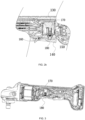
FIG. 1 is a structural view of a power tool according to a first example of the present application; -
FIG. 2a is a schematic view showing internal structures of the power tool provided inFIG. 1 when a contact rod is in a first stage; -
FIG. 2b is an enlarged sectional view showing internal structures of the power tool provided inFIG. 2a when a contact rod is in a first stage; -
FIG. 3 is a schematic view showing internal structures of the power tool provided inFIG. 1 when a contact rod is in a second stage; -
FIG. 4 is a perspective view of an operating assembly of the power tool provided inFIG. 1 ; -
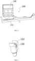
FIG. 5 is a perspective view of a contact rod of the power tool provided inFIG. 1 ; -
FIG. 6 is a schematic view showing an internal structure of a contact rod of the power tool provided inFIG. 1 ; -
FIG. 7 is a structural view of a mounting cavity of a contact rod of the power tool provided inFIG. 1 ; -
FIG. 8 is a schematic view showing internal structures of a power tool according to a second example of the present application; -
FIG. 9 is a sectional view of an operating assembly of the power tool provided inFIG. 8 ; -
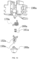
FIG. 10 is an exploded view of an operating assembly of the power tool provided inFIG. 8 ; -
FIG. 11 is a structural view of a power tool according to a third example of the present application; -
FIG. 12 is a schematic view showing internal structures of the power tool provided inFIG. 11 ; -
FIG. 13 is a structural view of a power tool according to a fourth example of the present application; and -
FIG. 14 is a schematic view showing internal structures of the power tool provided inFIG. 11 . - Examples of the present application are described below in detail with reference to the drawings. The same or similar reference numerals indicate the same or similar elements or elements having the same or similar functions. The examples described below with reference to the drawings are only intended to explain the present application and are not to be construed as limiting the present application.
- Technical solutions of the present application are further described below through the examples in conjunction with the drawings. Referring to
FIGS. 1 to 3 , the present application provides apower tool 100, where thepower tool 100 may be a tool which needs to be controlled by a switch to be turned on, for example, an angle grinder, an electric drill, an electric hammer, or a polisher. Thepower tool 100 includes ahousing 110, anelectric motor 120, and a working assembly, where theelectric motor 120 drives the working assembly to run. In the present application, the angle grinder is used as an example for describing the specific structure of thepower tool 100. When thepower tool 100 is the angle grinder, the work assembly includes an output shaft and a working accessory, where the working accessory may be a grinding disc or the like, and theelectric motor 120 drives, through the output shaft, the working accessory to rotate to perform a polishing operation. - The
power tool 100 further includes aswitch 130, theelectric motor 120 is disposed in thehousing 110, and theswitch 130 can control theelectric motor 120 to be turned on and off. Theswitch 130 may be a switch with a relatively short stroke such as a microswitch or a membrane switch so that a cost can be reduced and the volume of the whole power tool can be reduced. Theswitch 130 may be triggered by a small force. Thepower tool 100 further includes anoperating element 140 for a user to operate. The user presses theoperating element 140 to trigger theswitch 130 so as to turn on theelectric motor 120. - Referring to
FIGS. 2a to 4 , thepower tool 100 further includes acontact rod 150 and apressing block 160, thecontact rod 150 is connected to theoperating element 140, and theoperating element 140 can push thecontact rod 150 to move along a straight line from a first stage to a second stage. Thecontact rod 150 is supported directly or indirectly by thehousing 110, and the contact rod can be in contact with theoperating element 140. Thepressing block 160 is disposed between thecontact rod 150 and theswitch 130, and thecontact rod 150 drives thepressing block 160 to be in contact with theswitch 130 and press atrigger point 131 to trigger theswitch 130. Thepressing block 160 is separated from thetrigger point 131 when thecontact rod 150 is in the first stage, and thetrigger point 131 of the switch is pressed and triggered by thepressing block 160 when thecontact rod 150 is in the second stage. Thus, when the user presses theoperating element 140, theoperating element 140 drives thecontact rod 150 to enter the first stage from an initial position and move, and thecontact rod 150 drives thepressing block 160 to move toward thetrigger point 131. In this case, the movement of theoperating element 140 is an idle stroke. Even though the user presses theoperating element 140, thecontact rod 150 in the first stage cannot drive thepressing block 160 to be in contact with theswitch 130, and theswitch 130 is not triggered in this case. As the user continues pressing theoperating element 140, theoperating element 140 continues pushing thecontact rod 150 such that thecontact rod 150 enters the second stage, and thecontact rod 150 drives thepressing block 160 to be in contact with thetrigger point 131. As the user presses theoperating element 140, thepressing block 160 is pushed to press thetrigger point 131 such that theswitch 130 is triggered and theelectric motor 120 is turned on. Thecontact rod 150 enters an end position when theoperating element 140 is pushed to the end of the stroke. The ratio of the stroke of thecontact rod 150 in the first stage to the stroke of thecontact rod 150 in the second stage is higher than or equal to 1 and lower than or equal to 1.5. The problem that theswitch 130 is easy to trigger can be solved through the configuration of thecontact rod 150 in the first stage. Thus, thepower tool 100 does not start theelectric motor 120 by mistake because of a vibration and a false trigger of the user, and thepower tool 100 is prevented from suddenly running and hurting the user. Referring toFIGS. 2a ,2b, and 3 , thepower tool 100 further includes areset element 170 connected to thecontact rod 150. Thereset element 170 is disposed between theswitch 130 and thecontact rod 150, and thereset element 170 is not in contact with thetrigger point 131. Thereset element 170 is an elastic member, which may be a spring, a compression spring, a tension spring, a torsion spring, a spiral spring, a rubber ring, a steel wire, an airbag, or the like. When thecontact rod 150 moves in the first stage, thecontact rod 150 compresses thereset element 170. Thus, thereset element 170 absorbs a pressure supplied to theoperating element 140 by the user so that the user can be effectively prevented from triggering theoperating element 140 by mistake to start theelectric motor 120 and the safety of thepower tool 100 is improved. After the user drives, by pressing theoperating element 140, thecontact rod 150 to enter the second stage, theswitch 130 is pressed by thepressing block 160, and thecontact rod 150 is located in the middle of the initial position and the end position or at the end position. After the user finishes using thepower tool 100, theoperating element 140 is released. In this case, thereset element 170 releases thecontact rod 150 and pushes thecontact rod 150 to return to the initial position such that thecontact rod 150 and thepressing block 160 are reset. - Referring to
FIG. 6 , thepower tool 100 further includes a biasingelement 180 connecting thecontact rod 150 to thepressing block 160, compressing the stroke of thecontact rod 150, and then transmitting the stroke of thecontact rod 150 to thepressing block 160. The biasingelement 180 is also the elastic member, which may be the spring, the compression spring, the tension spring, the torsion spring, the spiral spring, the rubber ring, the steel wire, the airbag, or the like. The biasingelement 180 is disposed between thepressing block 160 and thecontact rod 150. After thecontact rod 150 enters the second stage, thepressing block 160 is in contact with thetrigger point 131 of theswitch 130, and the user continues pressing theoperating element 140 so that thecontact rod 150 continues moving toward theswitch 130. Thus, thecontact rod 150 approaches theswitch 130, and thepressing block 160 and the biasingelement 180 between theswitch 130 and thecontact rod 150 are squeezed so that the biasingelement 180 is compressed and pushes thepressing block 160 to press thetrigger point 131 at the same time. The biasingelement 180 is provided so that the stroke transmitted to thepressing block 160 by thecontact rod 150 can be compressed. The biasingelement 180 can be used for buffering a pressing force of the user to theoperating element 140 so that the reliability of anoperating assembly 200 integrally constituted by thecontact rod 150, theoperating element 140, thepressing block 160, and theswitch 130 is improved. In addition, the biasingelement 180 can be used for buffering the pressing force of the user to theoperating element 140 so that theswitch 130 is effectively protected and the service life of theswitch 130 is prolonged. Additionally, the biasingelement 180 provides an elastic force for thepressing block 160 so that it is ensured that theswitch 130 is prevented from being reset due to vibrations during the working of thepower tool 100 and causing an abnormal shutdown. - Optionally, referring to
FIGS. 5 to 7 , a mountingcavity 151 is formed in the middle portion of thecontact rod 150, and the biasingelement 180 and thepressing block 160 are placed in the mountingcavity 151. The whole mountingcavity 151 extends along the direction of a firststraight line 101. When the user presses theoperating element 140, thecontact rod 150 is driven to move along the firststraight line 101 toward a first direction, where the direction in which thecontact rod 150 moves at this time is set as the front direction. The biasingelement 180 and thepressing block 160 are arranged successively along the direction of the firststraight line 101, thepressing block 160 is located in front of the biasingelement 180, and the biasingelement 180 is located between thepressing block 160 and the bottom wall of the mountingcavity 151 of thecontact rod 150. The biasingelement 180 can be in contact with thepressing block 160. When thecontact rod 150 is at the initial position, one end of thepressing block 160 is not in contact with theswitch 130, and the other end of thepressing block 160 is connected to the biasingelement 180 or disposed toward the biasingelement 180. The user presses theoperating element 140 to drive thecontact rod 150 to enter the first stage from the initial position. In this case, thecontact rod 150 drives thepressing block 160 and the biasingelement 180 to move along the first direction. The user presses theoperating element 140 to drive thecontact rod 150 and thepressing block 160 to move along the first direction until one end of thepressing block 160 is in contact with thetrigger point 131 of theswitch 130. Thecontact rod 150 provides pressure in the first direction for the biasingelement 180, and thetrigger point 131 of theswitch 130 abuts against thepressing block 160, thereby compressing the biasingelement 180 together to compress the stroke of thecontact rod 150 and transmit the compressed stroke to thepressing block 160. After the user releases theoperating element 140, thereset element 170 squeezes thecontact rod 150 to drive thecontact rod 150 and thepressing block 160 to be reset so that thecontact rod 150 returns to the initial position. - In a first example of the present application, the
contact rod 150 includes connectingholes 153, and thepressing block 160 is provided with a connectingpin 162, where the connectingpin 162 is placed into the connectingholes 153 so that thecontact rod 150 and thepressing block 160 are connected to each other and are movable relative to each other in the direction of the firststraight line 101. Both the biasingelement 180 and thereset element 170 are springs and extend in the direction of the firststraight line 101 so that both the biasingelement 180 and thereset element 170 can be telescopic substantially along the direction of the firststraight line 101. Thefirst line 101 passes through theswitch 130, and thetrigger point 131 can be pushed in a direction parallel to thefirst line 101 so that theelectric motor 120 is turned on. The connectingholes 153 extend to certain lengths in the direction of the firststraight line 101 so that thepressing block 160 and thecontact rod 150 can move a certain distance relative to each other in the direction of the firststraight line 101, thereby causing thepressing block 160 and thecontact rod 150 to move relative to each other at different speeds. Optionally, when thecontact rod 150 is in the second stage, the ratio of the elastic force of the biasingelement 180 to the elastic force of thetrigger point 131 is higher than or equal to 2 and lower than or equal to 3, thereby improving the overall reliability of the operatingassembly 200 and improving the feel of the user. - Optionally, the
power tool 100 further includes aswitch box 190, where at least part of theswitch 130, thecontact rod 150, and thereset element 170 are configured to be supported by theswitch box 190, and thecontact rod 150 is indirectly supported by thehousing 110 in this case. Optionally, at least part of theswitch 130, thecontact rod 150, and thereset element 170 are disposed in theswitch box 190. Thecontact rod 150 includes an exposed portion exposed from theswitch box 190, and the exposed portion of thecontact rod 150 is in contact with or connected to theoperating element 140 so that theoperating element 140 can drive thecontact rod 150 to move or thecontact rod 150 drives theoperating element 140 to move. The operatingassembly 200 is packaged by theswitch box 190 so that the operatingassembly 200 is modular and adaptable to a variety ofpower tools 100. Theswitch box 190 is sealed by a sealing member so that the operating assembly 200 in theswitch box 190 is protected against dust. Theswitch box 190 may have a two-half structure. An accommodating space is formed in the middle of the two-half structure through splicing. The joint of the two-half switch box 190 is sealed by the sealing member, where the sealing member may be made of a sealing material such as silica gel. Thepower tool 100 further includes a dust-proof member 191 surrounding the exposed portion of thecontact rod 150. The dust-proof member 191 is an elastic member and can deform as thecontact rod 150 moves and is always in the state of wrapping thecontact rod 150. The dust-proof member 191 may be made of a rubber material. The dust-proof member 191 is connected to theswitch box 190 so that the inside of the dust-proof member 191 communicates with the accommodating space formed by theswitch box 190. Thewhole operating assembly 200 is located in the accommodating space formed by theswitch box 190 and the accommodating space formed by the dust-proof member 191. A relatively airtight dust-proof space is integrally formed by theswitch box 190 and the dust-proof member 191. - The
contact rod 150 is supported directly or indirectly by thehousing 110, and thecontact rod 150 can be in contact with theoperating element 140. Optionally, thecontact rod 150 abuts against the operatingelement 140. Optionally, when theoperating element 140 is not pressed by the user, there is a gap between thecontact rod 150 and theoperating element 140, theoperating element 140 is pressed such that thecontact rod 150 and theoperating element 140 are in contact with each other, and theoperating element 140 is continuously pressed such that thecontact rod 150 is pushed to move. - Optionally, the
contact rod 150 is rotatably connected to the housing directly or indirectly, and thecontact rod 150 can be pushed by theoperating element 140 to rotate so that thepressing block 160 is driven to move toward the switch and trigger theswitch 130 to be turned on. - The
electric motor 120 includes an electric motor shaft extending along afirst axis 102, where the firststraight line 101 is a radial direction of thefirst axis 102. In this example, theoperating element 140 is rotatable relative to the housing. Theoperating element 140 is configured to be a trigger. The user presses theoperating element 140 to drive thecontact rod 150 to move, where the direction in which theoperating element 140 is pressed is substantially the same as the direction of the firststraight line 101. Thetrigger point 131 can be pushed in a direction parallel to the firststraight line 101 so that theelectric motor 120 is turned on. Thecontact rod 150 and thepressing block 160 can be driven by the trigger to move along the firststraight line 101 and can be driven by thereset element 170 so that thecontact rod 150 and thepressing block 160 return to the initial position along the firststraight line 101. - The stroke range of the
operating element 140 is greater than or equal to 4 mm and less than or equal to 6 mm so that the stroke range of thecontact rod 150 is greater than or equal to 4 mm and less than or equal to 6 mm, and the ratio of the stroke of thecontact rod 150 in the first stage to the stroke of thecontact rod 150 in the second stage is higher than or equal to 1 and lower than or equal to 1.5. Thepower tool 100 with theswitch 130 is safer and less expensive than a current switch. However, the relatively short turn-on stroke of theswitch 130 is not applicable to a working condition of thepower tool 100 and the user's usage habits. Theswitch 130 is easily turned off by the vibrations generated when thepower tool 100 runs. If the stroke of theoperating element 140 coincides with the stroke of theswitch 130, it is inconvenient for the user to accurately manipulate thepower tool 100. In this case, the feel of using theoperating element 140 is poor. In addition, the structure of theswitch 130 is easily damaged, resulting in a relatively short life of theswitch 130. Thereset element 170 and the biasingelement 180 are provided so that the stroke of theswitch 130 is increased and it is implemented that the stroke range of theoperating element 140 is greater than or equal to 4 mm and less than or equal to 6 mm. Thus, the performance of theoperating element 140 more conforms to the working condition under which thepower tool 100 is used. The biasingelement 180 can effectively prevent theswitch 130 from being turned off due to the vibrations of thepower tool 100 and buffers the impact force of theoperating element 140, thereby reducing the impact on theswitch 130 and prolonging the service life of theswitch 130. - The mounting
cavity 151 is formed in the middle portion of thecontact rod 150, the biasingelement 180 and thepressing block 160 are placed in the mountingcavity 151, both thereset element 170 and the biasingelement 180 can be telescopic in the direction of the firststraight line 101, and the firststraight line 101 passes through theswitch 130 so that thewhole operating element 140 is simple and reliable. In addition, the overall structure of the operatingassembly 200 and theswitch box 190 is compact, and elements such as thecontact rod 150, thereset element 170, thepressing block 160 are added to increase the stroke of theoperating element 140, which does not make the overall structure of the operating assembly 200 complicated and increase the overall dimension of thepower tool 100 indirectly. - During assembly, the biasing
element 180 and thepressing block 160 are assembled in thecontact rod 150, and the connectingpin 162 is placed into the connectingholes 153 to limit thepressing block 160. Theswitch 130, thecontact rod 150, and thereset element 170 are assembled in theswitch box 190, the two-half switch box 190 is spliced by snaps or screws, the switch is encapsulated by the sealing member, and the dust-proof member 191 is sleeved on the exposed portion of thecontact rod 150. The whole constituted by the operatingassembly 200 and theswitch box 190 is then mounted in thehousing 110. - Optionally, the
power tool 100 provided by the present application may be provided with noswitch box 190, and the operatingassembly 200 is directly fixed or supported by thehousing 110. - Referring to
FIGS. 8 to 10 , in a second example of the present application, apower tool 100a is provided, and thepower tool 100a includes ahousing 110a, anelectric motor 120a, and anoperating assembly 200a, where theoperating assembly 200a includes aswitch 130a, anoperating element 140a, acontact rod 150a, apressing block 160a, and areset element 170a, theoperating element 140a is a trigger, theelectric motor 120a is disposed in thehousing 110a, theswitch 130a includes a trigger point 131a for controlling theelectric motor 120a to be turned on, and the trigger is operated to trigger theswitch 130a. Thepower tool 100a further includes aswitch box 190a, and at least part of theoperating assembly 200a is disposed in theswitch box 190a so that thewhole operating assembly 200a is modular. - The
contact rod 150a is connected to the trigger, the trigger can push thecontact rod 150a to move along a straight line to trigger theswitch 130a, thepressing block 160a is elastically connected to thecontact rod 150a, thepressing block 160a can be driven by thecontact rod 150a to push the trigger point 131a, and thereset element 170a is connected to thecontact rod 150a and theswitch box 190a. Theoperating element 140a can push thecontact rod 150a to move along the straight line from a first stage to a second stage. When the user does not press theoperating element 140a, thereset element 170a keeps thecontact rod 150a away from theswitch 130a so that thepressing block 160a and the trigger point 131a are separated from each other. When theoperating element 140a is pressed and thecontact rod 150a is in the first stage, thepressing block 160a is separated from the trigger point 131a. When the user presses theoperating element 140a so that thecontact rod 150a is in the second stage, thecontact rod 150a compresses thereset element 170a, and the trigger point 131a is pressed by thepressing block 160a such that theelectric motor 120a is turned on. - The
contact rod 150a includes a mountingslot 152a, thepressing block 160a is provided with an adapter 161a, and the adapter 161a is placed into the mountingslot 152a so that thepressing block 160a is positioned and thepressing block 160a and thecontact rod 150a are movable relative to each other in the direction of a firststraight line 101a. Both thereset element 170a and thebiasing element 180a can be telescopic in the direction of the firststraight line 101a passing through theswitch 130a. Theswitch box 190a includes a positioning pin, and thereset element 170a is configured to be a torsion spring and connected to the positioning pin. One end of thereset element 170a is connected to thecontact rod 150a. Thus, theoperating element 140a is pressed to perform a leading movement, which is an idle stroke. In addition, thecontact rod 150a and thepressing block 160a are reset by thereset element 170a so that it is convenient to control thepower tool 100a to be turned on next time. - Referring to
FIGS. 11 and 12 , in a third example of the present application, apower tool 100b is provided, the structure of thepower tool 100b is substantially the same as the structure of thepower tool 100b in the second example, and the third example differs from the second example in that at least one secondstraight line 103b perpendicular to the firststraight line 101b exists so that a projection of theswitch 130b in the direction of the secondstraight line 103b at least partially overlaps a projection of thecontact rod 150b in the direction of the secondstraight line 130b. A trigger point 131b of theswitch 130b can be pressed in the direction of the secondstraight line 103b so that the electric motor 120b is triggered to be turned on. Thepower tool 100b further includes acontact piece 163b abutting against the pressing block, and when thecontact rod 150b moves along the firststraight line 101b, thecontact piece 163b is driven by the pressing block to rotate to trigger theswitch 130b. Thecontact piece 163b has a curved design and is rotatably connected to theswitch 130b or theswitch box 190b, and a direction in which thecontact rod 150b is driven is shifted by thecontact piece 163b. Aresilient piece 180b is disposed between the pressing block and thecontact rod 150b, and the pressing block and thecontact rod 150b can move a certain distance relative to each other in the direction of the firststraight line 101b. - With the structural configuration in this example, the projection of the
switch 130b in the direction of the secondstraight line 103b at least partially overlaps the projection of thecontact rod 150b in the direction of the secondstraight line 103b. Thus, the dimension of the whole operating assembly in the direction of the firststraight line 101b can be reduced so that the dimension of theswitch box 190b is reduced. Further, it is implemented that the volume of theswitch box 190b is greater than or equal to 5000 cubic millimeters and less than or equal to 9500 cubic millimeters, and the area of a vertical projection of theswitch box 190b on the plane in which the firststraight line 101b and the secondstraight line 103b are located is greater than or equal to 400 square millimeters and less than or equal to 750 square millimeters. - Referring to
FIGS. 13 and 14 , in a fourth example of the present application, an operating element is apush button 142c which can push acontact rod 150c to move along a firststraight line 101c. An electric motor 120c includes an electric motor shaft extending along afirst axis 102c, where the firststraight line 101c is substantially parallel to thefirst axis 102c, that is, the firststraight line 101c is parallel to thefirst axis 102c or the included angle formed by the firststraight line 101c and thefirst axis 102c is less than 30 degrees. - A user pushes the operating element to drive the
contact rod 150c to move, where the direction in which the operating element is pushed is substantially the same as the direction of the firststraight line 101c. A trigger point can be pushed in a direction parallel to the firststraight line 101c so that the electric motor 120c is turned on. Thecontact rod 150c and apressing block 160c can be driven by a trigger to move along the firststraight line 101c and can be driven by areset element 170c so that thecontact rod 150c and thepressing block 160c return to an initial position along the firststraight line 101c. In this example, thecontact rod 150c, thereset element 170c, and a switch 130c are directly supported by ribs formed by the housing 110c, and no switch box 190c is provided. Thereset element 170c may be disposed between the switch 130c and thecontact rod 150c. Optionally, one end of thereset element 170c is connected to a housing 110c or fixed to a connector of the housing 110c, and the other end of thereset element 170c is connected to the switch 130c. A biasing element is disposed between thepressing block 160c and thecontact rod 150c so that thepressing block 160c and thecontact rod 150c can move a certain distance relative to each other in the direction of the firststraight line 101c.
Claims (21)
- A power tool, comprising:a housing;an electric motor disposed in the housing;a switch comprising a trigger point for controlling the electric motor to be turned on;an operating element to be operated to trigger the switch;a contact rod supported by the housing, wherein the operating element is capable of pushing the contact rod to move;a pressing block elastically connected to the contact rod and capable of being driven by the contact rod to push the trigger point; anda reset element connected to the contact rod.
- The power tool according to claim 1, wherein the operating element is capable of pushing the contact rod to move along a straight line.
- The power tool according to claim 1, whereina mounting cavity is formed in the contact rod, and the pressing block is disposed in the mounting cavity; andthe power tool further comprises:
a biasing element disposed in the mounting cavity, connecting the contact rod to the pressing block, and causing the contact rod and the pressing block to move at different speeds. - The power tool according to claim 3, wherein
the electric motor comprises an electric motor shaft extending along a first axis, and the operating element is a push button capable of being pushed along a first straight line, wherein the first straight line is substantially parallel to the first axis. - The power tool according to claim 1, wherein
the electric motor comprises an electric motor shaft extending along a first axis, the operating element is rotatably connected to the housing, and the contact rod and the pressing block are capable of being driven by the operating element to move along a first straight line and are capable of being reset by the reset element, wherein the first straight line is a radial direction of the first axis. - The power tool according to claim 5, wherein the first straight line passes through the switch, and the trigger point is capable of being pushed in a direction parallel to the first straight line so that the electric motor is turned on.
- The power tool according to claim 5, wherein at least one second straight line perpendicular to the first straight line exists, wherein a projection of the switch in a direction of the second straight line at least partially overlaps a projection of the contact rod in the direction of the second straight line.
- The power tool according to claim 7, further comprising:
a contact piece abutting against the pressing block, wherein when the contact rod moves along the first straight line, the contact piece is capable of being driven by the pressing block to rotate so as to trigger the switch. - The power tool according to any one of claims 1 to 8, further comprising:
a switch box supporting the switch, the reset element, and at least part of the contact rod, wherein the contact rod comprises an exposed portion exposed from the switch box. - The power tool according to claim 9, further comprising:
a dust-proof member surrounding at least part of the exposed portion of the contact rod, wherein the exposed portion of the contact rod is in contact with the operating element. - The power tool according to claim 9, wherein
a volume of the switch box is greater than or equal to 5000 cubic millimeters and less than or equal to 9500 cubic millimeters. - A power tool, comprising:a housing;an electric motor disposed in the housing;a switch comprising a trigger point for controlling the switch to be turned on;an operating element to be operated to trigger the switch;a contact rod capable of abutting against the operating element to be pushed;a pressing block disposed between the contact rod and the trigger point, wherein the contact rod forms a mounting cavity, and the pressing block is at least partially disposed in the mounting cavity;a biasing element connecting the pressing block to the contact rod; anda switch box supporting the pressing block, the switch, the biasing element, and the contact rod.
- The power tool according to claim 12, whereinthe operating element is capable of pushing the contact rod to move along a straight line from a first stage to a second stage;wherein the pressing block is separated from the trigger point when the contact rod is in the first stage, the trigger point is pressed and triggered by the pressing block when the contact rod is in the second stage, and a ratio of a stroke of the contact rod in the first stage to a stroke of the contact rod in the second stage is higher than or equal to 1 and lower than or equal to 1.5.
- The power tool according to claim 12, wherein
the biasing element compresses a stroke of the contact rod and transmits the stroke of the contact rod to the pressing block, and the biasing element is disposed in the mounting cavity. - The power tool according to claim 14, further comprising:
a reset element connected to the contact rod, wherein the contact rod compresses the reset element when the contact rod moves in a first stage. - The power tool according to claim 15, wherein
the contact rod and the pressing block are capable of being driven by the operating element to move along a first straight line and are capable of being reset by the reset element. - The power tool according to claim 16, wherein
the contact rod comprises connecting holes, and the pressing block is provided with a connecting pin, wherein the connecting pin is placed into the connecting holes so that the contact rod and the pressing block are connected to each other and are movable relative to each other in a direction of the first straight line. - The power tool according to claim 16, wherein
the contact rod comprises a mounting slot, the pressing block is provided with an adapter, and the adapter is placed into the mounting slot so that the pressing block is positioned and the pressing block and the contact rod are movable relative to each other in a direction of the first straight line. - The power tool according to claim 15, wherein
the reset element is disposed in the switch box. - The power tool according to claim 13, wherein
a ratio of an elastic force of the biasing element to an elastic force of the trigger point is higher than or equal to 2 and lower than or equal to 3 when the contact rod is in the second stage. - The power tool according to claim 12, wherein
a stroke range of the operating element is greater than or equal to 4 mm and less than or equal to 6 mm.
Applications Claiming Priority (5)
| Application Number | Priority Date | Filing Date | Title |
|---|---|---|---|
| CN202110316496 | 2021-03-25 | ||
| CN202110316477 | 2021-03-25 | ||
| CN202111503453.2A CN114055408B (en) | 2021-03-25 | 2021-12-09 | Electric tool |
| CN202111503443.9A CN115132505A (en) | 2021-03-25 | 2021-12-09 | Electric tool |
| PCT/CN2022/074489 WO2022199249A1 (en) | 2021-03-25 | 2022-01-28 | Electric tool |
Publications (3)
| Publication Number | Publication Date |
|---|---|
| EP4283644A1 true EP4283644A1 (en) | 2023-11-29 |
| EP4283644A4 EP4283644A4 (en) | 2024-07-10 |
| EP4283644B1 EP4283644B1 (en) | 2025-09-10 |
Family
ID=83396322
Family Applications (1)
| Application Number | Title | Priority Date | Filing Date |
|---|---|---|---|
| EP22773911.7A Active EP4283644B1 (en) | 2021-03-25 | 2022-01-28 | Electric tool |
Country Status (3)
| Country | Link |
|---|---|
| US (1) | US12609252B2 (en) |
| EP (1) | EP4283644B1 (en) |
| WO (1) | WO2022199249A1 (en) |
Family Cites Families (12)
| Publication number | Priority date | Publication date | Assignee | Title |
|---|---|---|---|---|
| JPH06223674A (en) * | 1993-01-27 | 1994-08-12 | Omron Corp | Trigger switch |
| JPH09223434A (en) * | 1996-02-19 | 1997-08-26 | Omron Corp | Trigger switch |
| US6717080B1 (en) * | 2003-05-22 | 2004-04-06 | Defond Components Limited | Power tool trigger assembly |
| CN100374234C (en) * | 2004-06-01 | 2008-03-12 | 南京德朔实业有限公司 | jig saw |
| JP5611780B2 (en) * | 2010-11-11 | 2014-10-22 | 株式会社マキタ | Shift switch |
| JP6119340B2 (en) * | 2013-03-19 | 2017-04-26 | オムロン株式会社 | switch |
| JP6277042B2 (en) * | 2014-04-01 | 2018-02-07 | 株式会社マキタ | Electric tool |
| CN204029621U (en) * | 2014-08-20 | 2014-12-17 | 马夸特开关(上海)有限公司 | High capacity direct current electric power tools switch |
| JP6879797B2 (en) * | 2017-03-30 | 2021-06-02 | 佐鳥電機株式会社 | Trigger switch |
| CN208055964U (en) * | 2017-06-06 | 2018-11-06 | 浙江亚特电器有限公司 | A kind of safe electric tool |
| CN212485151U (en) | 2020-07-31 | 2021-02-05 | 江苏华频电子科技有限公司 | Switch structure and electric tool |
| CN212365786U (en) | 2020-09-09 | 2021-01-15 | 南京德朔实业有限公司 | Switch assembly and electric tool |
-
2022
- 2022-01-28 EP EP22773911.7A patent/EP4283644B1/en active Active
- 2022-01-28 WO PCT/CN2022/074489 patent/WO2022199249A1/en not_active Ceased
-
2023
- 2023-08-17 US US18/451,236 patent/US12609252B2/en active Active
Also Published As
| Publication number | Publication date |
|---|---|
| US20240047148A1 (en) | 2024-02-08 |
| EP4283644A4 (en) | 2024-07-10 |
| EP4283644B1 (en) | 2025-09-10 |
| WO2022199249A1 (en) | 2022-09-29 |
| US12609252B2 (en) | 2026-04-21 |
Similar Documents
| Publication | Publication Date | Title |
|---|---|---|
| CN100436077C (en) | power tool | |
| US11845169B2 (en) | Impact tool | |
| US11679482B2 (en) | Power tool | |
| US8978951B2 (en) | Auto hammer | |
| CN102145486B (en) | Electric power tool | |
| JP4424853B2 (en) | Electrical switch | |
| CN115464604A (en) | Rotary Impact Tool | |
| CN114055408B (en) | Electric tool | |
| EP4283644B1 (en) | Electric tool | |
| CN115132505A (en) | Electric tool | |
| US20250058447A1 (en) | Power tool having a hammer mechanism | |
| CN218397491U (en) | Electric tool | |
| US11969868B2 (en) | Power tool having hammer mechanism | |
| CN217121949U (en) | Electric tool | |
| EP0392428A2 (en) | Trigger switch | |
| CN220914080U (en) | Control assembly and handheld power tool | |
| WO2022242327A1 (en) | Angle grinder | |
| CN219882130U (en) | Angle grinder | |
| CN219562976U (en) | Garden tool handle and garden tool | |
| CN119839657B (en) | Hydrostatic spindle device and machine tool | |
| CN102577847A (en) | Handheld electric tool with improved trigger | |
| CN222487250U (en) | Self-moving robot | |
| CN216849689U (en) | Limit switch | |
| CN223957326U (en) | Charging clamp | |
| CN220796528U (en) | Key switch with trigger travel and skirting switch for closestool |
Legal Events
| Date | Code | Title | Description |
|---|---|---|---|
| STAA | Information on the status of an ep patent application or granted ep patent |
Free format text: STATUS: THE INTERNATIONAL PUBLICATION HAS BEEN MADE |
|
| PUAI | Public reference made under article 153(3) epc to a published international application that has entered the european phase |
Free format text: ORIGINAL CODE: 0009012 |
|
| STAA | Information on the status of an ep patent application or granted ep patent |
Free format text: STATUS: REQUEST FOR EXAMINATION WAS MADE |
|
| 17P | Request for examination filed |
Effective date: 20230821 |
|
| AK | Designated contracting states |
Kind code of ref document: A1 Designated state(s): AL AT BE BG CH CY CZ DE DK EE ES FI FR GB GR HR HU IE IS IT LI LT LU LV MC MK MT NL NO PL PT RO RS SE SI SK SM TR |
|
| REG | Reference to a national code |
Ref country code: DE Ref legal event code: R079 Ref document number: 602022021275 Country of ref document: DE Free format text: PREVIOUS MAIN CLASS: H01H0003260000 Ipc: H01H0009060000 |
|
| DAV | Request for validation of the european patent (deleted) | ||
| DAX | Request for extension of the european patent (deleted) | ||
| A4 | Supplementary search report drawn up and despatched |
Effective date: 20240610 |
|
| RIC1 | Information provided on ipc code assigned before grant |
Ipc: H01H 3/46 20060101ALN20240604BHEP Ipc: H01H 3/38 20060101ALN20240604BHEP Ipc: H01H 9/04 20060101ALN20240604BHEP Ipc: B25F 5/02 20060101ALI20240604BHEP Ipc: H01H 13/20 20060101ALI20240604BHEP Ipc: H01H 13/08 20060101ALI20240604BHEP Ipc: H01H 9/06 20060101AFI20240604BHEP |
|
| STAA | Information on the status of an ep patent application or granted ep patent |
Free format text: STATUS: EXAMINATION IS IN PROGRESS |
|
| 17Q | First examination report despatched |
Effective date: 20250214 |
|
| RIC1 | Information provided on ipc code assigned before grant |
Ipc: H01H 9/06 20060101AFI20250612BHEP Ipc: H01H 13/08 20060101ALI20250612BHEP Ipc: H01H 13/20 20060101ALI20250612BHEP Ipc: B25F 5/02 20060101ALI20250612BHEP Ipc: H01H 9/04 20060101ALN20250612BHEP Ipc: H01H 3/38 20060101ALN20250612BHEP Ipc: H01H 3/46 20060101ALN20250612BHEP |
|
| GRAP | Despatch of communication of intention to grant a patent |
Free format text: ORIGINAL CODE: EPIDOSNIGR1 |
|
| STAA | Information on the status of an ep patent application or granted ep patent |
Free format text: STATUS: GRANT OF PATENT IS INTENDED |
|
| GRAS | Grant fee paid |
Free format text: ORIGINAL CODE: EPIDOSNIGR3 |
|
| GRAA | (expected) grant |
Free format text: ORIGINAL CODE: 0009210 |
|
| STAA | Information on the status of an ep patent application or granted ep patent |
Free format text: STATUS: THE PATENT HAS BEEN GRANTED |
|
| RIC1 | Information provided on ipc code assigned before grant |
Ipc: H01H 9/06 20060101AFI20250704BHEP Ipc: H01H 13/08 20060101ALI20250704BHEP Ipc: H01H 13/20 20060101ALI20250704BHEP Ipc: B25F 5/02 20060101ALI20250704BHEP Ipc: H01H 9/04 20060101ALN20250704BHEP Ipc: H01H 3/38 20060101ALN20250704BHEP Ipc: H01H 3/46 20060101ALN20250704BHEP |
|
| INTG | Intention to grant announced |
Effective date: 20250718 |
|
| AK | Designated contracting states |
Kind code of ref document: B1 Designated state(s): AL AT BE BG CH CY CZ DE DK EE ES FI FR GB GR HR HU IE IS IT LI LT LU LV MC MK MT NL NO PL PT RO RS SE SI SK SM TR |
|
| REG | Reference to a national code |
Ref country code: GB Ref legal event code: FG4D |
|
| REG | Reference to a national code |
Ref country code: CH Ref legal event code: EP |
|
| REG | Reference to a national code |
Ref country code: DE Ref legal event code: R096 Ref document number: 602022021275 Country of ref document: DE |
|
| REG | Reference to a national code |
Ref country code: IE Ref legal event code: FG4D |
|
| PG25 | Lapsed in a contracting state [announced via postgrant information from national office to epo] |
Ref country code: NO Free format text: LAPSE BECAUSE OF FAILURE TO SUBMIT A TRANSLATION OF THE DESCRIPTION OR TO PAY THE FEE WITHIN THE PRESCRIBED TIME-LIMIT Effective date: 20251210 |
|
| REG | Reference to a national code |
Ref country code: LT Ref legal event code: MG9D |
|
| PG25 | Lapsed in a contracting state [announced via postgrant information from national office to epo] |
Ref country code: FI Free format text: LAPSE BECAUSE OF FAILURE TO SUBMIT A TRANSLATION OF THE DESCRIPTION OR TO PAY THE FEE WITHIN THE PRESCRIBED TIME-LIMIT Effective date: 20250910 |
|
| REG | Reference to a national code |
Ref country code: NL Ref legal event code: MP Effective date: 20250910 |
|
| PG25 | Lapsed in a contracting state [announced via postgrant information from national office to epo] |
Ref country code: HR Free format text: LAPSE BECAUSE OF FAILURE TO SUBMIT A TRANSLATION OF THE DESCRIPTION OR TO PAY THE FEE WITHIN THE PRESCRIBED TIME-LIMIT Effective date: 20250910 |
|
| PG25 | Lapsed in a contracting state [announced via postgrant information from national office to epo] |
Ref country code: GR Free format text: LAPSE BECAUSE OF FAILURE TO SUBMIT A TRANSLATION OF THE DESCRIPTION OR TO PAY THE FEE WITHIN THE PRESCRIBED TIME-LIMIT Effective date: 20251211 |
|
| PG25 | Lapsed in a contracting state [announced via postgrant information from national office to epo] |
Ref country code: SE Free format text: LAPSE BECAUSE OF FAILURE TO SUBMIT A TRANSLATION OF THE DESCRIPTION OR TO PAY THE FEE WITHIN THE PRESCRIBED TIME-LIMIT Effective date: 20250910 |
|
| PG25 | Lapsed in a contracting state [announced via postgrant information from national office to epo] |
Ref country code: LV Free format text: LAPSE BECAUSE OF FAILURE TO SUBMIT A TRANSLATION OF THE DESCRIPTION OR TO PAY THE FEE WITHIN THE PRESCRIBED TIME-LIMIT Effective date: 20250910 |
|
| PG25 | Lapsed in a contracting state [announced via postgrant information from national office to epo] |
Ref country code: PL Free format text: LAPSE BECAUSE OF FAILURE TO SUBMIT A TRANSLATION OF THE DESCRIPTION OR TO PAY THE FEE WITHIN THE PRESCRIBED TIME-LIMIT Effective date: 20250910 Ref country code: BG Free format text: LAPSE BECAUSE OF FAILURE TO SUBMIT A TRANSLATION OF THE DESCRIPTION OR TO PAY THE FEE WITHIN THE PRESCRIBED TIME-LIMIT Effective date: 20250910 |
|
| PG25 | Lapsed in a contracting state [announced via postgrant information from national office to epo] |
Ref country code: RS Free format text: LAPSE BECAUSE OF FAILURE TO SUBMIT A TRANSLATION OF THE DESCRIPTION OR TO PAY THE FEE WITHIN THE PRESCRIBED TIME-LIMIT Effective date: 20251210 |
|
| PG25 | Lapsed in a contracting state [announced via postgrant information from national office to epo] |
Ref country code: ES Free format text: LAPSE BECAUSE OF FAILURE TO SUBMIT A TRANSLATION OF THE DESCRIPTION OR TO PAY THE FEE WITHIN THE PRESCRIBED TIME-LIMIT Effective date: 20250910 |
|
| REG | Reference to a national code |
Ref country code: AT Ref legal event code: MK05 Ref document number: 1836851 Country of ref document: AT Kind code of ref document: T Effective date: 20250910 |
|
| PG25 | Lapsed in a contracting state [announced via postgrant information from national office to epo] |
Ref country code: NL Free format text: LAPSE BECAUSE OF FAILURE TO SUBMIT A TRANSLATION OF THE DESCRIPTION OR TO PAY THE FEE WITHIN THE PRESCRIBED TIME-LIMIT Effective date: 20250910 |
|
| PG25 | Lapsed in a contracting state [announced via postgrant information from national office to epo] |
Ref country code: SM Free format text: LAPSE BECAUSE OF FAILURE TO SUBMIT A TRANSLATION OF THE DESCRIPTION OR TO PAY THE FEE WITHIN THE PRESCRIBED TIME-LIMIT Effective date: 20250910 |
|
| PG25 | Lapsed in a contracting state [announced via postgrant information from national office to epo] |
Ref country code: AT Free format text: LAPSE BECAUSE OF FAILURE TO SUBMIT A TRANSLATION OF THE DESCRIPTION OR TO PAY THE FEE WITHIN THE PRESCRIBED TIME-LIMIT Effective date: 20250910 |
|
| PG25 | Lapsed in a contracting state [announced via postgrant information from national office to epo] |
Ref country code: IT Free format text: LAPSE BECAUSE OF FAILURE TO SUBMIT A TRANSLATION OF THE DESCRIPTION OR TO PAY THE FEE WITHIN THE PRESCRIBED TIME-LIMIT Effective date: 20250910 |
|
| PG25 | Lapsed in a contracting state [announced via postgrant information from national office to epo] |
Ref country code: IS Free format text: LAPSE BECAUSE OF FAILURE TO SUBMIT A TRANSLATION OF THE DESCRIPTION OR TO PAY THE FEE WITHIN THE PRESCRIBED TIME-LIMIT Effective date: 20260110 |
|
| PG25 | Lapsed in a contracting state [announced via postgrant information from national office to epo] |
Ref country code: PT Free format text: LAPSE BECAUSE OF FAILURE TO SUBMIT A TRANSLATION OF THE DESCRIPTION OR TO PAY THE FEE WITHIN THE PRESCRIBED TIME-LIMIT Effective date: 20260112 Ref country code: CZ Free format text: LAPSE BECAUSE OF FAILURE TO SUBMIT A TRANSLATION OF THE DESCRIPTION OR TO PAY THE FEE WITHIN THE PRESCRIBED TIME-LIMIT Effective date: 20250910 |
|
| PG25 | Lapsed in a contracting state [announced via postgrant information from national office to epo] |
Ref country code: EE Free format text: LAPSE BECAUSE OF FAILURE TO SUBMIT A TRANSLATION OF THE DESCRIPTION OR TO PAY THE FEE WITHIN THE PRESCRIBED TIME-LIMIT Effective date: 20250910 Ref country code: SK Free format text: LAPSE BECAUSE OF FAILURE TO SUBMIT A TRANSLATION OF THE DESCRIPTION OR TO PAY THE FEE WITHIN THE PRESCRIBED TIME-LIMIT Effective date: 20250910 |
|
| REG | Reference to a national code |
Ref country code: DE Ref legal event code: R097 Ref document number: 602022021275 Country of ref document: DE |
|
| PG25 | Lapsed in a contracting state [announced via postgrant information from national office to epo] |
Ref country code: LT Free format text: LAPSE BECAUSE OF FAILURE TO SUBMIT A TRANSLATION OF THE DESCRIPTION OR TO PAY THE FEE WITHIN THE PRESCRIBED TIME-LIMIT Effective date: 20250910 |
|
| PG25 | Lapsed in a contracting state [announced via postgrant information from national office to epo] |
Ref country code: DK Free format text: LAPSE BECAUSE OF FAILURE TO SUBMIT A TRANSLATION OF THE DESCRIPTION OR TO PAY THE FEE WITHIN THE PRESCRIBED TIME-LIMIT Effective date: 20250910 |
|
| PLBE | No opposition filed within time limit |
Free format text: ORIGINAL CODE: 0009261 |
|
| STAA | Information on the status of an ep patent application or granted ep patent |
Free format text: STATUS: NO OPPOSITION FILED WITHIN TIME LIMIT |
|
| REG | Reference to a national code |
Ref country code: CH Ref legal event code: L10 Free format text: ST27 STATUS EVENT CODE: U-0-0-L10-L00 (AS PROVIDED BY THE NATIONAL OFFICE) Effective date: 20260722 |