EP4283594A1 - Flight simulation system - Google Patents
Flight simulation system Download PDFInfo
- Publication number
- EP4283594A1 EP4283594A1 EP23173532.5A EP23173532A EP4283594A1 EP 4283594 A1 EP4283594 A1 EP 4283594A1 EP 23173532 A EP23173532 A EP 23173532A EP 4283594 A1 EP4283594 A1 EP 4283594A1
- Authority
- EP
- European Patent Office
- Prior art keywords
- operational
- flight simulation
- head
- user
- location
- Prior art date
- Legal status (The legal status is an assumption and is not a legal conclusion. Google has not performed a legal analysis and makes no representation as to the accuracy of the status listed.)
- Granted
Links
Images






Classifications
-
- G—PHYSICS
- G09—EDUCATION; CRYPTOGRAPHY; DISPLAY; ADVERTISING; SEALS
- G09B—EDUCATIONAL OR DEMONSTRATION APPLIANCES; APPLIANCES FOR TEACHING, OR COMMUNICATING WITH, THE BLIND, DEAF OR MUTE; MODELS; PLANETARIA; GLOBES; MAPS; DIAGRAMS
- G09B9/00—Simulators for teaching or training purposes
- G09B9/02—Simulators for teaching or training purposes for teaching control of vehicles or other craft
- G09B9/08—Simulators for teaching or training purposes for teaching control of vehicles or other craft for teaching control of aircraft, e.g. Link trainer
- G09B9/24—Simulators for teaching or training purposes for teaching control of vehicles or other craft for teaching control of aircraft, e.g. Link trainer including display or recording of simulated flight path
-
- G—PHYSICS
- G09—EDUCATION; CRYPTOGRAPHY; DISPLAY; ADVERTISING; SEALS
- G09B—EDUCATIONAL OR DEMONSTRATION APPLIANCES; APPLIANCES FOR TEACHING, OR COMMUNICATING WITH, THE BLIND, DEAF OR MUTE; MODELS; PLANETARIA; GLOBES; MAPS; DIAGRAMS
- G09B9/00—Simulators for teaching or training purposes
- G09B9/02—Simulators for teaching or training purposes for teaching control of vehicles or other craft
- G09B9/08—Simulators for teaching or training purposes for teaching control of vehicles or other craft for teaching control of aircraft, e.g. Link trainer
- G09B9/30—Simulation of view from aircraft
- G09B9/307—Simulation of view from aircraft by helmet-mounted projector or display
-
- G—PHYSICS
- G06—COMPUTING OR CALCULATING; COUNTING
- G06F—ELECTRIC DIGITAL DATA PROCESSING
- G06F3/00—Input arrangements for transferring data to be processed into a form capable of being handled by the computer; Output arrangements for transferring data from processing unit to output unit, e.g. interface arrangements
- G06F3/01—Input arrangements or combined input and output arrangements for interaction between user and computer
- G06F3/011—Arrangements for interaction with the human body, e.g. for user immersion in virtual reality
-
- G—PHYSICS
- G06—COMPUTING OR CALCULATING; COUNTING
- G06F—ELECTRIC DIGITAL DATA PROCESSING
- G06F3/00—Input arrangements for transferring data to be processed into a form capable of being handled by the computer; Output arrangements for transferring data from processing unit to output unit, e.g. interface arrangements
- G06F3/01—Input arrangements or combined input and output arrangements for interaction between user and computer
- G06F3/011—Arrangements for interaction with the human body, e.g. for user immersion in virtual reality
- G06F3/012—Head tracking input arrangements
-
- G—PHYSICS
- G06—COMPUTING OR CALCULATING; COUNTING
- G06F—ELECTRIC DIGITAL DATA PROCESSING
- G06F3/00—Input arrangements for transferring data to be processed into a form capable of being handled by the computer; Output arrangements for transferring data from processing unit to output unit, e.g. interface arrangements
- G06F3/01—Input arrangements or combined input and output arrangements for interaction between user and computer
- G06F3/016—Input arrangements with force or tactile feedback as computer generated output to the user
-
- G—PHYSICS
- G06—COMPUTING OR CALCULATING; COUNTING
- G06F—ELECTRIC DIGITAL DATA PROCESSING
- G06F3/00—Input arrangements for transferring data to be processed into a form capable of being handled by the computer; Output arrangements for transferring data from processing unit to output unit, e.g. interface arrangements
- G06F3/01—Input arrangements or combined input and output arrangements for interaction between user and computer
- G06F3/03—Arrangements for converting the position or the displacement of a member into a coded form
- G06F3/033—Pointing devices displaced or positioned by the user, e.g. mice, trackballs, pens or joysticks; Accessories therefor
- G06F3/0354—Pointing devices displaced or positioned by the user, e.g. mice, trackballs, pens or joysticks; Accessories therefor with detection of two-dimensional [2D] relative movements between the device, or an operating part thereof, and a plane or surface, e.g. 2D mice, trackballs, pens or pucks
- G06F3/03547—Touch pads, in which fingers can move on a surface
-
- G—PHYSICS
- G06—COMPUTING OR CALCULATING; COUNTING
- G06F—ELECTRIC DIGITAL DATA PROCESSING
- G06F3/00—Input arrangements for transferring data to be processed into a form capable of being handled by the computer; Output arrangements for transferring data from processing unit to output unit, e.g. interface arrangements
- G06F3/01—Input arrangements or combined input and output arrangements for interaction between user and computer
- G06F3/048—Interaction techniques based on graphical user interfaces [GUI]
- G06F3/0487—Interaction techniques based on graphical user interfaces [GUI] using specific features provided by the input device, e.g. functions controlled by the rotation of a mouse with dual sensing arrangements, or of the nature of the input device, e.g. tap gestures based on pressure sensed by a digitiser
- G06F3/0488—Interaction techniques based on graphical user interfaces [GUI] using specific features provided by the input device, e.g. functions controlled by the rotation of a mouse with dual sensing arrangements, or of the nature of the input device, e.g. tap gestures based on pressure sensed by a digitiser using a touch-screen or digitiser, e.g. input of commands through traced gestures
-
- G—PHYSICS
- G09—EDUCATION; CRYPTOGRAPHY; DISPLAY; ADVERTISING; SEALS
- G09B—EDUCATIONAL OR DEMONSTRATION APPLIANCES; APPLIANCES FOR TEACHING, OR COMMUNICATING WITH, THE BLIND, DEAF OR MUTE; MODELS; PLANETARIA; GLOBES; MAPS; DIAGRAMS
- G09B9/00—Simulators for teaching or training purposes
- G09B9/02—Simulators for teaching or training purposes for teaching control of vehicles or other craft
- G09B9/08—Simulators for teaching or training purposes for teaching control of vehicles or other craft for teaching control of aircraft, e.g. Link trainer
- G09B9/16—Ambient or aircraft conditions simulated or indicated by instrument or alarm
- G09B9/165—Condition of cabin, cockpit or pilot's accessories
-
- G—PHYSICS
- G09—EDUCATION; CRYPTOGRAPHY; DISPLAY; ADVERTISING; SEALS
- G09B—EDUCATIONAL OR DEMONSTRATION APPLIANCES; APPLIANCES FOR TEACHING, OR COMMUNICATING WITH, THE BLIND, DEAF OR MUTE; MODELS; PLANETARIA; GLOBES; MAPS; DIAGRAMS
- G09B9/00—Simulators for teaching or training purposes
- G09B9/02—Simulators for teaching or training purposes for teaching control of vehicles or other craft
- G09B9/08—Simulators for teaching or training purposes for teaching control of vehicles or other craft for teaching control of aircraft, e.g. Link trainer
- G09B9/30—Simulation of view from aircraft
- G09B9/301—Simulation of view from aircraft by computer-processed or -generated image
- G09B9/302—Simulation of view from aircraft by computer-processed or -generated image the image being transformed by computer processing, e.g. updating the image to correspond to the changing point of view
-
- G—PHYSICS
- G06—COMPUTING OR CALCULATING; COUNTING
- G06F—ELECTRIC DIGITAL DATA PROCESSING
- G06F3/00—Input arrangements for transferring data to be processed into a form capable of being handled by the computer; Output arrangements for transferring data from processing unit to output unit, e.g. interface arrangements
- G06F3/01—Input arrangements or combined input and output arrangements for interaction between user and computer
- G06F3/048—Interaction techniques based on graphical user interfaces [GUI]
- G06F3/0484—Interaction techniques based on graphical user interfaces [GUI] for the control of specific functions or operations, e.g. selecting or manipulating an object, an image or a displayed text element, setting a parameter value or selecting a range
- G06F3/04847—Interaction techniques to control parameter settings, e.g. interaction with sliders or dials
Definitions
- the disclosure relates to a flight simulation system.
- Some known flight simulation systems include dome screens. With these flight simulation systems including dome screens, a reproduction of an aircraft cockpit seat is made inside the dome, and simulated experiences of actual aircraft flight are provided in an exact manner. On the other hand, the flight simulation systems including dome screens usually occupy relatively large space, and additionally, this kind of systems are costly. There are other small-scale and low-cost technologies for providing simulated experiences of actual aircraft flight.
- One example is the flight simulation system using a head-mounted display described in Japanese Unexamined Patent Application Publication (Translation of PCT Application) (JP-T) No. 2021-513122 .
- An aspect of the disclosure provides a flight simulation system configured to perform flight simulation of models of aircrafts.
- the flight simulation system includes a head-mounted display, a haptic device, and a control device.
- the head-mounted display is wearable by a user, configured to display a virtual reality image of a cockpit of an aircraft in a virtual space.
- the haptic device is disposed in a real space at a location corresponding to operational interfaces provided in the cockpit in the virtual reality image.
- the control device is configured to control the flight simulation using the head-mounted display and the haptic device.
- the haptic device includes a touch sensor configured to detect a touch location touched by the user on the haptic device and a vibrator configured to cause a vibration at the touch location.
- the control device includes a processor and a memory configured to store coordinate data indicating coordinate locations of the operational interfaces provided in the cockpit of each of the models.
- the processor is configured to execute a process including: performing flight simulation of a model selected by the user from the models; causing the head-mounted display to display the virtual reality image picturing the operational interfaces of the selected model; when the user touches the haptic device, causing the vibrator to cause a vibration at the touch location; based on the coordinate data of the selected model and the touch location, identifying an operational interface corresponding to the touch location among the operational interfaces of the selected model; and applying a change based on an operation performed on the identified operational interface to the flight simulation of the selected model.
- the above-mentioned flight simulation system using a known head-mounted display includes physical input hardware of human machine interfaces (HMIs) such as a control yoke, rudder pedals, and switches.
- HMIs human machine interfaces
- the arrangement of operational interfaces such as an instrument panel and various kinds of switches can differ among different models of aircrafts.
- HMIs are to be prepared for the individual aircraft models. This makes it difficult for a single flight simulation system to handle multiple models of aircrafts.
- FIG. 1 schematically illustrates an overall configuration of the flight simulation system 1 according to the first embodiment.
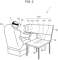
- FIG. 2 is a perspective view illustrating an example of a use case of the flight simulation system 1 according to the first embodiment.
- FIG. 3 schematically illustrates an example of a virtual reality image 400 displayed in the flight simulation system 1 according to the first embodiment.
- the flight simulation system 1 is configured to perform flight simulation of multiple models of aircrafts. As illustrated in FIGs. 1 and 2 , the flight simulation system 1 includes a control device 10, a head-mounted display 20, a haptic device 30, a control yoke 40, rudder pedals 50, and a cockpit seat 60.
- the control device 10 may be implemented by, for example, a personal computer, tablet computer, or smartphone.
- the control device 10 is coupled to the head-mounted display 20, the haptic device 30, the control yoke 40, and the rudder pedals 50 in a wired or wireless manner that enables mutual communications.
- the control device 10 controls flight simulation using the head-mounted display 20 and the haptic device 30. Flight simulation is to simulate flight situations for the purpose of providing piloting training or on-board experiences of flights with, for example, an aircraft. In the flight simulation according to the present embodiment, for example, while flight situations with a particular aircraft are reproduced in a virtual space, mock flight with an aircraft 402 is carried out in the virtual space based on operations by a user 2 in the real space.
- the real space is a space in which the flight simulation system 1 is installed in reality.
- the virtual space is an artificial space on a computer, created by arithmetic operation by, for example, a computer.
- the control device 10 controls mock flight with the aircraft 402 reproduced in the virtual space based on operations by the user 2 in the real space.
- the control device 10 includes a processor 12 and a memory 14 that is coupled to the processor 12.
- the processor 12 is an arithmetic processing unit installed in a computer.
- the processor 12 is implemented by, for example, a central processing unit (CPU).
- the processor 12 may be implemented by another kind of microprocessor.
- the processor 12 may be implemented by one or multiple processors.
- the processor 12 runs a program stored in the memory 14 or another storage medium to perform various operations with the control device 10.
- the memory 14 is a storage medium for storing programs and other various kinds of data.
- the memory 14 includes, for example, a random-access memory (RAM) and a read-only memory (ROM).
- the ROM is a non-volatile memory for storing the program to be run by the processor 12 and, for example, data to be used to run the program.
- the RAM is a volatile memory for temporarily storing data including variables to be used in operations performed by the processor 12, operational parameters, and operational results.
- the program stored in the ROM is loaded on the RAM and run by the processor 12 implemented by, for example, a CPU.
- the head-mounted display 20 is a display device that is wearable on the head of the user 2. As illustrated in FIG. 2 , for example, the head-mounted display 20 is a non-see-through display device that is mountable to block the entire field of vision of the user 2.
- the head-mounted display 20 is coupled to the control device 10 in a manner that enables communication.
- the head-mounted display 20 receives information from the control device 10 and displays images of flight simulation for the user 2.
- the head-mounted display 20 displays, for example, the virtual reality image 400.
- the virtual reality image 400 is an image of a cockpit 404 of the aircraft 402 in the virtual space.
- the virtual reality image 400 includes, for example, images of operational interfaces 411, 412, 413, 414, and 415 (hereinafter also referred to simply as the "operational interfaces 410" in a collective manner) provided inside the cockpit 404 and an image of an instrument panel 420.
- the operational interfaces 410 are various kinds of control equipment disposed inside the cockpit 404 of the aircraft 402.
- the operational interfaces 410 are, for example, various operating tools and devices used for flight control of the aircraft 402, piloting of the aircraft 402, and other kinds of control relating to flight operation of the aircraft 402.
- the operational interfaces 410 may be, for example, physical operating tools used for piloting of the aircraft 402 such as switches, levers, knobs, and buttons, or a touch panel or other interfaces that virtually display these physical operating tools.
- Examples of the operational interfaces 410 may include a push-button switch, a toggle switch, a rocker switch, a rotary switch, and a slide switch.
- the instrument panel 420 is a display device for visually indicating values measured by, for example, various sensors provided in the aircraft 402.
- the virtual reality image 400 includes, for example, an image of an external environment 406 (hatched in FIG. 3 ) outside the aircraft 402, viewed from the cockpit 404.
- the external environment 406 is the environment outside the aircraft 402 in the virtual space; the external environment 406 is, for example, the view of the sky or ground viewable from the cockpit 404.
- the head-mounted display 20 includes an external camera 22 and a posture sensor 24.
- the external camera 22 is an example of an imager.
- the external camera 22 is implemented by, for example, a visible light camera.
- the external camera 22 is not limited to a visible light camera and may be implemented by, for example, a near-infrared camera.
- the external camera 22 is provided at, for example, the front of the outer side of the head-mounted display 20.
- the external camera 22 captures images of the surrounding environment around the head-mounted display 20 in the real space.
- the external camera 22 captures images of the surrounding environment around the cockpit seat 60 of the user 2.
- the external camera 22 mainly captures images of the environment in front of the user 2.
- Examples of the posture sensor 24 include a gyro sensor, an angular velocity sensor, and an acceleration sensor.
- the posture sensor 24 is provided in the head-mounted display 20.
- the posture sensor 24 senses various kinds of motion, posture, and orientation of the head of the user 2 wearing the head-mounted display 20. For example, when the user 2 wearing the head-mounted display 20 turns their face to the right, the posture sensor 24 senses this posture and transmits information about the posture to the control device 10.
- the haptic device 30 is operable to provide skin sensation feedback for the user 2 with a tactile sensation caused by, for example, vibration, force, movements, heat, or static electricity.
- the haptic device 30 is formed by, for example, a touch panel shaped as a rectangular plate.
- One or more haptic devices 30 are disposed around the cockpit seat 60 where the user 2 sits.
- one haptic device 30 is disposed in front of the cockpit seat 60, and two other haptic devices 30 are disposed on the right side with respect to the cockpit seat 60; in total, three haptic devices 30 are provided.
- This example is, however, not to be interpreted as limiting. Two or fewer haptic devices 30 or four or more haptic devices 30 may be provided.
- the haptic device 30 may be disposed, for example, at the upper part in front of the cockpit seat 60 or on the left side with respect to the cockpit seat 60.
- the haptic devices 30 are disposed in the real space at the locations corresponding to the operational interfaces 410 provided in the cockpit 404 in the virtual reality image 400.
- the haptic device 30 is disposed at the location facing the cockpit seat 60 or the location on the right side with respect to the cockpit seat 60.
- the haptic devices 30 are positioned, for example, such that the distance and direction in the virtual space from the location of the cockpit seat where the user 2 sits to the coordinate locations of the operational interfaces 411, 412, 413, 414, and 415 illustrated in FIG. 3 are the same as the distance and direction in the real space from the location of the cockpit seat 60 where the user 2 sits to operational interface set locations 311, 312, 313, 314, and 315 (hereinafter also referred to simply as the "operational interface set locations 310" in a collective manner) illustrated in FIG. 2 .
- the operational interface set locations 310 are coordinate locations in the real space; the coordinate locations indicate specific locations on the surfaces of the haptic devices 30.
- the operational interface set locations 310 that are set on the surfaces of the haptic devices 30 respectively correspond to the coordinate locations of the operational interfaces 410 in the virtual space.
- three-dimensional coordinate locations are set for the individual operational interfaces 410 in the cockpit 404 of the aircraft 402 drawn in the virtual reality image 400.
- the three-dimensional coordinate locations (the virtual space) may be indicated by XYZ coordinates determined with respect to a first fixed reference location as the origin.
- the three-dimensional coordinate locations (the virtual space) of the operational interfaces 410 in the virtual reality image 400 are set at the locations corresponding to the three-dimensional coordinate locations (the real space) of the operational interfaces disposed in the cockpit of a real aircraft in the real space.
- the first fixed reference location may be, for example, a location in the center of the cockpit seat 60 or a location in the center of the cockpit 404 of the aircraft 402.
- the operational interface set locations 310 are set on the surfaces of the haptic devices 30 in the real space such that the operational interface set locations 310 respectively correspond to the three-dimensional coordinate locations (the virtual space) of the operational interfaces 410 in the virtual reality image 400.
- the operational interface set locations 310 may be indicated by XYZ coordinates determined with respect to a second fixed reference location as the origin on the surface of the haptic device 30.
- the second fixed reference location may be, for example, a location in the center of the surface of the haptic device 30 or a location of any of the four corners of the haptic device 30.
- the haptic device 30 includes a touch sensor 32, a vibrator 34, and a liquid crystal display 36.
- the touch sensor 32 is provided at the surface of the haptic device 30.
- the touch sensor 32 detects the touch location on the haptic device 30 at which the user 2 touches. For example, when a finger of the user 2 touches the surface of the haptic device 30, the touch sensor 32 detects the touch location and transmits information about the touch location to the control device 10.
- One or more vibrators 34 are disposed in the haptic device 30.
- multiple vibrators 34 may be vertically and horizontally disposed at particular intervals at the surface of the haptic device 30.
- the vibrator 34 causes vibrations at the touch location detected by the touch sensor 32.
- the vibrator 34 at or near the touch location detected by the touch sensor 32 causes vibrations.
- the liquid crystal display 36 is an example of a display.
- the liquid crystal display 36 is provided at the surface of the haptic device 30.
- the liquid crystal display 36 receives information transmitted by the control device 10 and displays an image relating to the information.
- the control yoke 40 is an operating tool useable by the user 2 to pilot the aircraft 402 in flight simulation.
- the control yoke 40 is disposed in front of the cockpit seat 60.
- the control yoke 40 is provided with a handle so that the user 2 holds the control yoke 40 with both hands.
- the control yoke 40 is coupled to the control device 10 in a manner that enables communication.
- information indicating details of the operation with the control yoke 40 is transmitted to the control device 10, and the control device 10 applies changes based on the details of the operation with the control yoke 40 to flight simulation.
- the operating tool for piloting the aircraft 402 is a control yoke, but this is not to be interpreted as limiting; the operating tool for piloting the aircraft 402 may be a control stick.
- the rudder pedals 50 are operating tools useable by the user 2 to pilot the aircraft 402 in flight simulation.
- the rudder pedals 50 are disposed at the lower part in front of the cockpit seat 60.
- the rudder pedals 50 are provided with pedals in the manner in which the user 2 can push down the rudder pedals 50 with their feet.
- the rudder pedals 50 are coupled to the control device 10 in a manner that enables communication.
- information indicating details of the operation with the rudder pedals 50 is transmitted to the control device 10, and the control device 10 applies changes based on the details of the operation with the rudder pedals 50 to flight simulation.
- the nose of the aircraft 402 flying in flight simulation is caused to turn in a different direction.
- the cockpit seat 60 is a seat where the user 2 sits during flight simulation.
- the cockpit seat 60 may be, for example, a seat especially for flight simulation or a seat for general purposes.
- the cockpit seat 60 is disposed near the haptic device 30, the control yoke 40, and the rudder pedals 50, facing the haptic device 30, the control yoke 40, and the rudder pedals 50.
- the user 2 sitting in the cockpit seat 60 can operate with their own hands and feet the haptic device 30, the control yoke 40, and the rudder pedals 50.
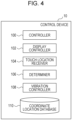
- FIG. 4 is a block diagram illustrating an example of the functional configuration of the flight simulation system 1 according to the first embodiment.
- the control device 10 includes a controller 100, a display controller 102, a touch location receiver 104, a determiner 106, a vibration controller 108, and a coordinate location database 110.
- the coordinate location database 110 is previously stored in the memory 14.
- first coordinate data, second coordinate data, identification information of the operational interface 410 are associated with each other.
- the processor 12 searches the coordinate location database 110 using any one information item out of the first coordinate data, the second coordinate data, and the identification information of the operational interface 410, so that the processor 12 uniquely extracts other information items associated with the one information item.
- the coordinate location database 110 has a table in which the first coordinate data, the second coordinate data, and the identification information of the operational interface 410 are associated with each other for individual aircraft models.
- the first coordinate data is coordinate data about individual aircraft models, indicating the coordinate locations (the virtual space) of the operational interfaces 410 provided in the cockpit 404 of the aircraft 402 in the virtual space with respect to each aircraft model.
- the first coordinate data according to the present embodiment indicates the individual coordinate locations of the operational interfaces 410 included in the virtual reality image 400 illustrated in FIG. 3 .
- the second coordinate data is coordinate data indicating the coordinate locations (the real space) on the surface of the haptic device 30 in the real space, corresponding to the coordinate locations (the virtual space) of the operational interfaces 410.
- the second coordinate data indicates the coordinate locations (the real space) of the operational interface set locations 310 on the surface of the haptic device 30 illustrated in FIG. 2 .
- the operational interface set locations 311, 312, 313, 314, and 315 (the real space) in the real space respectively correspond to the coordinate locations (the virtual space) of the operational interfaces 411, 412, 413, 414, and 415 in the virtual reality image 400.
- the identification information of the operational interface 410 is identification information for identifying the individual operational interfaces 410.
- the identification information of the operational interface 410 may be an identification number or identification code generated for the individual operational interfaces 410. Because the kinds and numbers of operational interfaces 410 provided in the cockpit 404 vary among different aircraft models, the identification information of the operational interface 410 is set differently for individual aircraft models. With this identification information, the individual operational interfaces 410 provided in the cockpit 404 of the aircraft 402 of each model are uniquely identified.
- the controller 100 controls flight simulation. For example, the controller 100 performs flight simulation of one model selected by the user 2 from multiple models. For example, the controller 100 reproduces in the virtual space a mock flight of the aircraft 402 of one model selected by the user 2 and controls the mock flight. For example, in response to operations performed by the user 2 with the haptic device 30, the control yoke 40, the rudder pedals 50, and other elements, the controller 100 applies changes based on details of the operations to the flight in the ongoing flight simulation.
- the controller 100 also controls, for example, outside environments other than the aircraft 402 in the virtual space.
- the outside environments are environmental conditions that can affect flight with the aircraft 402, such as weather, temperature, and wind speed.
- the display controller 102 causes the head-mounted display 20 to display images relating to flight simulation.
- the display controller 102 causes the head-mounted display 20 to display the virtual reality image 400 illustrated in FIG. 2 .
- the display controller 102 causes the head-mounted display 20 to display, for example, the virtual reality image 400 picturing the operational interfaces 410 provided in the cockpit 404 of the model selected by the user 2.
- the display controller 102 also changes the displayed appearance of the cockpit 404 in the virtual reality image 400 based on, for example, the detection result from the posture sensor 24.
- the display controller 102 changes the displayed appearance of the cockpit 404 in the virtual reality image 400 displayed on the head-mounted display 20, for example, in association with various kinds of motion, posture, and orientation of the head of the user 2 wearing the head-mounted display 20. For example, when the user 2 wearing the head-mounted display 20 sits in the cockpit seat 60 and faces forward, the display controller 102 causes the head-mounted display 20 to display the virtual reality image 400 picturing the area viewed on the front side with respect to the cockpit seat, out of the areas of the cockpit 404 in the virtual space.
- the display controller 102 causes the head-mounted display 20 to display the virtual reality image 400 picturing the area viewed on the right side with respect to the cockpit seat, out of the areas of the cockpit 404 in the virtual space.
- the virtual reality image 400 picturing the area viewed on the left side, back side, upper side, or lower side with respect to the cockpit seat is displayed out of the areas of the cockpit 404.
- the display controller 102 is operable to provide control to display the virtual reality image 400 in all 360-degree directions of the cockpit 404 of the aircraft 402 in the virtual space, for example, in association with various kinds of motion, posture, and orientation of the head of the user 2 sensed by the posture sensor 24. This improves the immersive feeling of the user 2 in flight simulation.
- the touch location receiver 104 obtains the second coordinate data from the touch sensor 32. For example, when a finger of the user 2 touches the operational interface set location 310 on the surface of the haptic device 30, the touch location receiver 104 obtains the second coordinate data of the operational interface set location 310 corresponding to the touch location from the touch sensor 32. For example, when a finger of the user 2 touches the particular operational interface set location 311 on the surface of the haptic device 30, the touch sensor 32 detects the coordinate location of the operational interface set location 311 as the touch location and transmits the second coordinate data of the operational interface set location 311 to the control device 10. The touch location receiver 104 obtains the second coordinate data of the operational interface set location 311 transmitted by the touch sensor 32. By receiving this second coordinate data, a particular operational interface 410 is identified as the operational interface 410 operated by the user 2 in flight simulation.
- the determiner 106 determines whether a finger of the user 2 has touched the haptic devices 30 based on, for example, the detection result on the haptic devices 30 from the touch sensor 32. For example, the determiner 106 determines whether a finger of the user 2 has touched any of the operational interface set locations 310 configured on the surface of the haptic device 30. For example, when a finger of the user 2 touches the particular operational interface set location 311 on the surface of the haptic device 30, the touch sensor 32 detects the coordinate location of the operational interface set location 311 as the touch location and transmits the second coordinate data of the operational interface set location 311 to the control device 10. When the second coordinate data of the operational interface set location 311 is transmitted from the touch sensor 32, the determiner 106 determines that a finger of the user 2 has touched the operational interface set location 311.
- the determiner 106 also identifies, based on the coordinate location database 110 and a touch location (the operational interface set location 310), the operational interface 410 corresponding to the touch location and the coordinate location of the operational interfaces 410. For example, using the second coordinate data corresponding to the touch location obtained by the touch location receiver 104, the determiner 106 searches the coordinate location database 110 of one particular model selected by the user 2, detects the identification information and first coordinate data of a particular operational interface 410 associated with the second coordinate data. In this manner, the determiner 106 identifies the particular operational interface 410 and the coordinate location of the particular operational interface 410.
- a particular operational interface 410 is one operational interface 410 corresponding to the touch location (the operational interface set location 310) out of the operational interfaces 410 disposed in the cockpit 404 of a particular model selected by the user 2.
- the determiner 106 identifies, as the operational interface 410 corresponding to the touch location, the operational interface 411 in the virtual reality image 400 illustrated in FIG. 3 and the coordinate location of the operational interface 411.
- the touch location receiver 104 obtains the second coordinate data of the operational interface set location 311 that is the touch location in the real space.
- the determiner 106 searches the coordinate location database 110 using the second coordinate data and obtains the identification information and first coordinate data of the operational interface 411 associated with the second coordinate data. Based on the identification information and first coordinate data of the operational interface 411, the determiner 106 identifies the operational interface 411 and the coordinate location of the operational interface 411.
- the determiner 106 may also search the coordinate location database 110 using the second coordinate data obtained by the touch location receiver 104 and determines whether the identification information and first coordinate data of the operational interface 410 corresponding to the second coordinate data are registered in the coordinate location database 110. As a result, when the first coordinate data is not registered, it is determined that the touch on the haptic device 30 by the user 2 is not on the operational interfaces 410.
- the vibration controller 108 controls vibration of the vibrator 34.
- the vibration controller 108 causes the vibrator 34 to cause vibrations at the touch location on the surface of the haptic device 30.
- the vibration controller 108 causes the vibrator 34 to cause vibrations at the touch location.
- the vibration controller 108 may change the vibration mode of the vibrator 34 depending on the kind of the one operational interface 410 identified in the virtual space based on the touch location. For example, when the one operational interface 410 identified based on the touch location is a push-button switch, the vibration controller 108 causes the vibrator 34 to cause vibrations at the following two time points: when the button is pressed down, and when the button is released. When the one operational interface 410 identified based on the touch location is a toggle switch, the vibration controller 108 causes the vibrator 34 to cause a vibration once when the toggle switch is flicked.
- FIG. 5 is a flowchart illustrating a flight simulation control process performed by the control device 10 according to the first embodiment.
- the user 2 selects an aircraft model targeted for flight simulation from multiple models (step S100).
- the controller 100 designates the model selected by the user 2 as the model with which flight simulation is to be performed.
- the display controller 102 obtains from the memory 14 the virtual reality image 400 picturing the operational interfaces 410 provided in the cockpit 404 of the model selected by the user 2.
- the display controller 102 then causes the head-mounted display 20 to display the obtained virtual reality image 400 (step S102).
- the controller 100 starts flight simulation of the selected model (step S104).
- the controller 100 and the display controller 102 change the appearance of the virtual reality image 400 displayed on the head-mounted display 20 based on simulation contents and details of operations performed by the user 2.
- the determiner 106 determines whether the user 2 has touched the operational interface set locations 310 on the surface of the haptic devices 30 (step S106).
- step S106 when it is determined that the user 2 has not touched the haptic devices 30 (NO in step S106), the process proceeds to step S116.
- the touch location receiver 104 obtains the second coordinate data of the operational interface set location 310 corresponding to the touch location from the touch sensor 32 (step S108). For example, when the touch location touched by the user 2 is the operational interface set location 311, the touch location receiver 104 obtains the second coordinate data of the operational interface set location 311 as the touch location from the touch sensor 32.
- the determiner 106 based on the second coordinate data of the operational interface set location 310 corresponding to the touch location obtained in step S108 and the coordinate location database 110, the determiner 106 identifies the operational interface 410 corresponding to the touch location and the coordinate location of the operational interface 410 (step S110).
- controller 100 applies changes based on the operation performed on the identified operational interface 410 to flight simulation of the selected model (step S112).
- the controller 100 determines that the operational interface 410 corresponding to the operational interface set location 310 is operated and applies changes based on details of the operation performed on the operational interface 410 to the flight in the ongoing flight simulation.
- the operational interface 411 is a switch for performing a particular operation with the aircraft 402
- the controller 100 determines that the operational interface 411 is operated and applies changes corresponding to the particular operation to the flight in the ongoing flight simulation.
- the controller 100 changes the operational interface 411 from OFF state to ON state.
- the controller 100 determines that the operational interface 411 is turned on and applies changes to the flight in flight simulation so that the engine of the aircraft 402 in the virtual space is started.
- the display controller 102 also applies changes based on the operation performed on the identified operational interface 410 to the virtual reality image 400 and causes the head-mounted display 20 to display the virtual reality image 400.
- the display controller 102 causes the head-mounted display 20 to display the virtual reality image 400 in which the operational interface 411 in the virtual space has been changed from OFF state to ON state.
- the vibration controller 108 causes vibrations at the touch location on the haptic device 30 in a vibration mode of the vibrator 34 corresponding to the kind of the identified operational interface 410 (step S114).
- step S106 When in step S106 it is determined that the user 2 has not touched the haptic device 30 (NO in step S106) or when the haptic device 30 is vibrated in step S114, the controller 100 determines whether flight simulation has ended (step S116). As a result, when it is determined that flight simulation has not ended (NO in step S116), the process is repeated from step S106 and flight simulation continues. By contrast, when it is determined that flight simulation has ended (YES in step S116), the flight simulation control process ends.
- the first coordinate data indicating the coordinate locations of the operational interfaces 410 provided in the cockpit 404 of the aircraft 402 of each model in the virtual space is previously stored. While flight simulation of the model selected by the user 2 is performed, when the user 2 touches the haptic device 30, the control device 10 identifies the operational interface 410 operated by the user 2, based on the coordinate location database 110, in which the first coordinate data and the second coordinate data are previously associated with each other, and the second coordinate data indicating the actual touch location.
- the flight simulation system 1 can perform flight simulation of the different models because the flight simulation system 1 reproduces the operational interfaces 410 of the different models in a virtual manner using the same haptic devices 30.
- the flight simulation system 1 For the purpose of performing flight simulation of one model selected from multiple models, hardware corresponding to the model is not to be prepared. As such, a flight simulation system with low costs and high general applicability is provided.
- the vibration controller 108 causes vibrations at the touch location with the vibrator 34.
- the user 2 performs an operation on the operational interface 410 displayed in the virtual reality image 400
- the user 2 is notified by vibration that an operation is performed on the operational interface 410.
- the user 2 can perform operations on the operational interfaces 410 in the virtual space in an assured manner.
- the vibration controller 108 changes the vibration mode of the vibrator 34 depending on the kind of the one operational interface 410 identified in the virtual space based on the touch location. As a result, based on the vibration mode, the user 2 can easily identify the operational interface 410 in the virtual space that is operated. This improves the usability of the haptic devices 30 in flight simulation and the reality of the operational interfaces 410.
- the flight simulation system 1 according to a second embodiment of the disclosure will be described in detail with reference to FIGs. 6 and 7 .
- the second embodiment is a modification of the first embodiment. The following mainly describes the points different from the first embodiment, and detailed descriptions of the same configurations, functions, and other details as the first embodiment are not repeated.
- the operational interface 410 in the virtual space and the coordinate location of the operational interface 410 are identified based on the coordinate location database 110 stored in the memory 14 and the touch location touched by the user 2 on the haptic device 30.
- the haptic devices 30 are to be disposed at proper coordinate locations (the real space) corresponding to the coordinate locations (the virtual space) of the operational interfaces 410.
- the operational interface set locations 310 on the haptic devices 30 in the real space are not coincident with the coordinate locations of the operational interfaces 410 indicated by the first coordinate data stored in the coordinate location database 110.
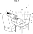
- two-dimensional bar codes 511, 512, 513, 514, and 515 (hereinafter also referred to simply as the "two-dimensional bar codes 510" in a collective manner) indicating the operational interface set locations 310 are displayed on the liquid crystal displays 36 of the haptic devices 30 (see FIG. 7 ), and the two-dimensional bar codes 510 are captured with the external camera 22 of the head-mounted display 20.
- the flight simulation system 1 according to the second embodiment it is possible to correct the coordinate locations of the operational interfaces 410 in the virtual space based on the displayed locations (in other words, the operational interface set locations 310) at which the two-dimensional bar codes 510 are displayed on the liquid crystal displays 36 in the real space.
- the coordinate locations of the operational interfaces 410 in the virtual space are made coincident with the displayed locations of the two-dimensional bar codes 510 in an exact manner.
- FIG. 6 is a block diagram illustrating an example of the functional configuration of the flight simulation system 1 according to the second embodiment.
- FIG. 7 is a perspective view illustrating an example of a use case of the flight simulation system 1 according to the second embodiment may be used.
- the control device 10 of the flight simulation system 1 according to the second embodiment includes, in addition to the controller 100, the display controller 102, the touch location receiver 104, the determiner 106, the vibration controller 108, and the coordinate location database 110 that are the constituent elements of the control device 10 of the flight simulation system 1 according to the first embodiment, an identification information display controller 200, an identification information receiver 202, and a coordinate location corrector 204.
- the identification information display controller 200 causes the liquid crystal displays 36 of the haptic devices 30 to display one or more two-dimensional bar codes 510.
- the two-dimensional bar code 510 is an example of identification information.
- the two-dimensional bar code 510 is identification information generated for the individual operational interfaces 410 in the virtual space so that the operational interfaces 410 are uniquely identified.
- the two-dimensional bar code 510 of the operational interface 410 is not necessarily a two-dimensional bar code as an example.
- the two-dimensional bar code 510 may be alternatively implemented as a quick response (QR) code (registered trademark), a one-dimensional bar code, text information such as identification information or identification code of the operational interface 410, or various kinds of patterns; otherwise, the two-dimensional bar code 510 may be implemented as any kind of information such as illumination modes of an infrared lamp when the information is created in the manner that enables identification of the operational interface 410.
- QR quick response
- the identification information display controller 200 refers to the coordinate location database 110 previously stored in the memory 14 and identifies a coordinate location on the surface of the haptic device 30 in the real space and a two-dimensional bar code 510 that correspond to a particular operational interface 410 of the operational interfaces 410 in the virtual space.
- the identification information display controller 200 then causes the haptic device 30 to display the two-dimensional bar code 510 corresponding to the particular operational interface 410 at the coordinate location on the haptic device 30.
- the identification information display controller 200 causes the liquid crystal displays 36 to display the two-dimensional bar codes 511, 512, 513, 514, and 515.
- the two-dimensional bar codes 511, 512, 513, 514, and 515 are identification information corresponding to the respective operational interfaces 411, 412, 413, 414, and 415 in the virtual reality image 400 illustrated in FIG. 3 .
- the identification information display controller 200 searches the coordinate location database 110 using the first coordinate data of the operational interface 411 in the virtual reality image 400 illustrated in FIG. 3 and extracts the second coordinate data corresponding to the first coordinate data.
- the identification information display controller 200 then causes the haptic device 30 in the real space to display the two-dimensional bar code 511 at the coordinate location on the surface of the haptic device 30 corresponding to the second coordinate data as illustrated in FIG. 7 .
- the two-dimensional bar code 510 is also stored in an associated manner.
- the identification information receiver 202 obtains, for example, the two-dimensional bar code 510 captured by the external camera 22 and an image capture location at which the two-dimensional bar code 510 is captured.
- the identification information receiver 202 obtains, for example, as the image capture location, the distance and direction from the location of the cockpit seat 60 in which the user 2 sits to the captured two-dimensional bar code 510.
- the coordinate location corrector 204 corrects the coordinate location of the operational interface 410 in the virtual space.
- the coordinate location corrector 204 determines, for example, whether the image capture location of the two-dimensional bar code 510 obtained by the identification information receiver 202 is coincident with the coordinate location of the operational interface 410 in the virtual space corresponding to the two-dimensional bar code 510.
- the coordinate location corrector 204 determines whether the distance and direction in the real space from the location of the cockpit seat 60 in which the user 2 sits to the captured two-dimensional bar code 510 are the same as the distance and direction in the virtual space from the location of the cockpit seat in which the user 2 sits to the coordinate location of the operational interface 410 corresponding to the two-dimensional bar code 510.
- the coordinate location corrector 204 corrects the coordinate location of the operational interface 410 in the virtual space. For example, based on the image capture location of the two-dimensional bar code 510 captured by the external camera 22, the coordinate location corrector 204 corrects the coordinate location of the operational interface 410 in the virtual space corresponding to the two-dimensional bar code 510.
- the coordinate location corrector 204 converts the distance and direction from the location of the cockpit seat 60 in which the user 2 sits to the captured two-dimensional bar code 510 into the distance and direction in the virtual space; the coordinate location corrector 204 then corrects the coordinate location of the operational interface 410 in the virtual space by designating the coordinate location of the same distance and direction in the virtual space from the location of the cockpit seat in which the user 2 sits as a new coordinate location of the operational interface 410 corresponding to the two-dimensional bar code 510.
- the display controller 102 provides display of the images picturing the operational interfaces 410 in the virtual space in the manner in which the images picturing the operational interfaces 410 are superimposed on the virtual reality image 400.
- the virtual reality image 400 is displayed with the image picturing the external environment 406, the image picturing the cockpit 404, the image picturing the instrument panel 420, and the images picturing the operational interfaces 410 that are superimposed in the order presented.
- the display controller 102 provides display of the images picturing the operational interfaces 410 corresponding to the two-dimensional bar codes 510 captured by the external camera 22 in the manner in which the images picturing the operational interfaces 410 are superimposed on the virtual reality image 400 displayed on the head-mounted display 20.
- the display controller 102 changes the image picturing the operational interface 410 from the coordinate location before correction to a new coordinate location after correction and then provides display of the image picturing the operational interface 410 in the manner in which the image picturing the operational interface 410 is superimposed on the virtual reality image 400.
- FIG. 8 is a flowchart illustrating a flight simulation control process performed by the control device 10 according to the second embodiment. Except for step S200, the process illustrated in FIG. 8 is the same as the flight simulation control process performed by the control device 10 according to the first embodiment illustrated in FIG. 5 , and descriptions of the steps other than step S200 are not repeated.
- step S200 the control device 10 performs a coordinate location correction process in FIG. 9 (step S200).
- step S200 the control device 10 causes the liquid crystal displays 36 of the haptic devices 30 to display the two-dimensional bar codes 510.
- the external camera 22 captures the two-dimensional bar codes 510, and the control device 10 obtains the image capture locations of the two-dimensional bar codes 510 from the external camera 22.
- the control device 10 subsequently determines whether the image capture locations of the two-dimensional bar code 510 are coincident with the coordinate locations of the operational interfaces 410 corresponding to the two-dimensional bar codes 510.
- the control device 10 corrects the coordinate locations of the operational interfaces 410 corresponding to the two-dimensional bar codes 510. Based on the corrected coordinate locations, the control device 10 causes the head-mounted display 20 to display the operational interfaces 410.
- step S104 illustrated in FIG. 8 The operations from step S104 to step S116 illustrated in FIG. 8 are the same as the operations from step S 104 to step S 116 of the flight simulation control process performed by the control device 10 according to the first embodiment illustrated in FIG. 5 , and descriptions of the operations are not repeated.
- FIG. 9 is a flowchart illustrating the coordinate location correction process (step S200) performed by the control device 10 according to the second embodiment.
- the identification information display controller 200 causes the liquid crystal displays 36 of the haptic devices 30 to display all the two-dimensional bar codes 510 representing the operational interfaces 410 provided in the cockpit 404 of one aircraft model selected by the user 2 (step S202).
- the liquid crystal displays 36 of the haptic devices 30 receive information from the identification information display controller 200 and display the two-dimensional bar codes 510 of the operational interfaces 410 at the locations in the real space corresponding to the operational interfaces 410.
- the external camera 22 of the head-mounted display 20 detects the two-dimensional bar codes 510 displayed on the liquid crystal displays 36 of the haptic devices 30.
- the identification information receiver 202 obtains the detected two-dimensional bar codes 510 and the image capture locations of the two-dimensional bar codes 510 from the external camera 22 (step S204).
- the coordinate location corrector 204 determines whether the image capture locations of the two-dimensional bar codes 510 obtained by the identification information receiver 202 are coincident with the coordinate locations of the operational interfaces 410 in the virtual space corresponding to the two-dimensional bar codes 510 (step S206).
- the coordinate location correction process ends.
- the coordinate location corrector 204 corrects the coordinate locations of the operational interfaces 410 in the virtual space corresponding to the two-dimensional bar codes 510 based on the image capture locations of the two-dimensional bar codes 510 obtained by the identification information receiver 202 (step S208).
- the display controller 102 changes the images picturing the operational interfaces 410 in the virtual space corresponding to the two-dimensional bar codes 510 from the coordinate locations before correction to new coordinate locations after correction and causes the head-mounted display 20 to display the images (step S210), and the coordinate location correction process ends.
- the display controller 102 provides display of the images picturing the operational interfaces 410 corresponding to the two-dimensional bar codes 510 at the coordinate locations after correction in the manner in which the images picturing the operational interfaces 410 are superimposed on the virtual reality image 400 displayed on the head-mounted display 20.
- the two-dimensional bar codes 510 are displayed on the liquid crystal displays 36, and the external camera 22 captures the two-dimensional bar codes 510.
- the coordinate location corrector 204 corrects the coordinate location of the operational interface 410 in the virtual space corresponding to the two-dimensional bar code 510.
- the display controller 102 provides display of the images of the operational interfaces 410 at the corrected coordinate locations of the operational interfaces 410 in the manner in which the images of the operational interfaces 410 are superimposed on the virtual reality image 400.
- the displayed locations of the two-dimensional bar codes 510 displayed on the liquid crystal displays 36 in the real space are made coincident with the coordinate locations of the operational interfaces 410 in the virtual space corresponding to the two-dimensional bar codes 510.
- the user 2 can exactly operate the operational interfaces 410 in the virtual space.
- the haptic device 30 is shaped as a rectangular plate, but this example is not to be interpreted as limiting.
- the haptic device 30 may be shaped as, for example, a polygonal plate or curved shape.
- the series of operations performed by the flight simulation system 1 may be implemented by software, hardware, or a combination of software and hardware.
- a program as software is previously stored in, for example, non-transitory media provided inside or outside the individual devices.
- the program is, for example, read from a non-transitory storage medium (for example, ROM), loaded on a temporary storage medium (for example, a RAM), and run by a processor such as a CPU.
- a program configured to execute a process implementing the functions of the flight simulation system 1 may be provided.
- a computer-readable non-transitory storage medium storing the program may be provided.
- the non-transitory storage medium may be, for example, a disk storage medium such as an optical disk, magnetic disk, or magneto-optical disk, or a semiconductor memory such as a flash memory or USB flash drive.
- the control device 10 illustrated in FIGs. 1 , 4 , and 6 can be implemented by circuitry including at least one semiconductor integrated circuit such as at least one processor (e.g., a central processing unit (CPU)), at least one application specific integrated circuit (ASIC), and/or at least one field programmable gate array (FPGA).
- processor e.g., a central processing unit (CPU)
- ASIC application specific integrated circuit
- FPGA field programmable gate array
- At least one processor can be configured, by reading instructions from at least one machine readable tangible medium, to perform all or a part of functions of the control device 10 including the controller 100, the display controller 102, the touch location receiver 104, the determiner 106, the vibration controller 108, and the coordinate location database 110, or the control device 10 including the controller 100, the display controller 102, the touch location receiver 104, the determiner 106, the vibration controller 108, the coordinate location database 110, the identification information display controller 200, the identification information receiver 202, and the coordinate location corrector 204.
- Such a medium may take many forms, including, but not limited to, any type of magnetic medium such as a hard disk, any type of optical medium such as a CD and a DVD, any type of semiconductor memory (i.e., semiconductor circuit) such as a volatile memory and a non-volatile memory.
- the volatile memory may include a DRAM and a SRAM
- the non-volatile memory may include a ROM and a NVRAM.
- the ASIC is an integrated circuit (IC) customized to perform
- the FPGA is an integrated circuit designed to be configured after manufacturing in order to perform, all or a part of the functions of the modules illustrated in FIGs. 1 , 4 , and 6 .
Landscapes
- Engineering & Computer Science (AREA)
- Theoretical Computer Science (AREA)
- General Engineering & Computer Science (AREA)
- General Physics & Mathematics (AREA)
- Physics & Mathematics (AREA)
- Human Computer Interaction (AREA)
- Business, Economics & Management (AREA)
- Educational Technology (AREA)
- Educational Administration (AREA)
- Aviation & Aerospace Engineering (AREA)
- Computer Hardware Design (AREA)
- User Interface Of Digital Computer (AREA)
- Processing Or Creating Images (AREA)
Abstract
Description
- The disclosure relates to a flight simulation system.
- Some known flight simulation systems include dome screens. With these flight simulation systems including dome screens, a reproduction of an aircraft cockpit seat is made inside the dome, and simulated experiences of actual aircraft flight are provided in an exact manner. On the other hand, the flight simulation systems including dome screens usually occupy relatively large space, and additionally, this kind of systems are costly. There are other small-scale and low-cost technologies for providing simulated experiences of actual aircraft flight. One example is the flight simulation system using a head-mounted display described in Japanese Unexamined Patent Application Publication (Translation of
PCT Application) (JP-T) No. 2021-513122 - An aspect of the disclosure provides a flight simulation system configured to perform flight simulation of models of aircrafts. The flight simulation system includes a head-mounted display, a haptic device, and a control device. The head-mounted display is wearable by a user, configured to display a virtual reality image of a cockpit of an aircraft in a virtual space. The haptic device is disposed in a real space at a location corresponding to operational interfaces provided in the cockpit in the virtual reality image. The control device is configured to control the flight simulation using the head-mounted display and the haptic device. The haptic device includes a touch sensor configured to detect a touch location touched by the user on the haptic device and a vibrator configured to cause a vibration at the touch location. The control device includes a processor and a memory configured to store coordinate data indicating coordinate locations of the operational interfaces provided in the cockpit of each of the models. The processor is configured to execute a process including: performing flight simulation of a model selected by the user from the models; causing the head-mounted display to display the virtual reality image picturing the operational interfaces of the selected model; when the user touches the haptic device, causing the vibrator to cause a vibration at the touch location; based on the coordinate data of the selected model and the touch location, identifying an operational interface corresponding to the touch location among the operational interfaces of the selected model; and applying a change based on an operation performed on the identified operational interface to the flight simulation of the selected model.
- The accompanying drawings are included to provide a further understanding of the disclosure and are incorporated in and constitute a part of this specification. The drawings illustrate embodiments and, together with the specification, serve to describe the principles of the disclosure.
-
FIG. 1 schematically illustrates an overall configuration of a flight simulation system according to an embodiment; -
FIG. 2 is a perspective view illustrating an example of a use case of the flight simulation system according to the embodiment; -
FIG. 3 schematically illustrates an example of a virtual reality image displayed in the flight simulation system according to the embodiment; -
FIG. 4 is a block diagram illustrating an example of the functional configuration of the flight simulation system according to the embodiment; -
FIG. 5 is a flowchart illustrating a flight simulation control process performed by a control device according to the embodiment; -
FIG. 6 is a block diagram illustrating an example of the functional configuration of a flight simulation system according to an embodiment; -
FIG. 7 is a perspective view illustrating an example of a use case of the flight simulation system according to the embodiment; -
FIG. 8 is a flowchart illustrating a flight simulation control process performed by a control device according to the embodiment; and -
FIG. 9 is a flowchart illustrating a coordinate location correction process performed by the control device according to the embodiment. - The above-mentioned flight simulation system using a known head-mounted display, described in
JP-T No. 2021-513122 - It is desirable to provide a flight simulation system with low costs and high general applicability.
- In the following, an embodiment of the disclosure is described in detail with reference to the accompanying drawings. Note that the following description is directed to an illustrative example of the disclosure and not to be construed as limiting to the disclosure. Factors including, without limitation, numerical values, shapes, materials, components, positions of the components, and how the components are coupled to each other are illustrative only and not to be construed as limiting to the disclosure. Further, elements in the following example embodiment which are not recited in a most-generic independent claim of the disclosure are optional and may be provided on an as-needed basis. The drawings are schematic and are not intended to be drawn to scale. Throughout the present specification and the drawings, elements having substantially the same function and configuration are denoted with the same numerals to avoid any redundant description.
- Firstly, the overall configuration of a
flight simulation system 1 according to a first embodiment of the disclosure will be described with reference toFIGs. 1 ,2 , and3 .FIG. 1 schematically illustrates an overall configuration of theflight simulation system 1 according to the first embodiment.FIG. 2 is a perspective view illustrating an example of a use case of theflight simulation system 1 according to the first embodiment.FIG. 3 schematically illustrates an example of avirtual reality image 400 displayed in theflight simulation system 1 according to the first embodiment. - The
flight simulation system 1 is configured to perform flight simulation of multiple models of aircrafts. As illustrated inFIGs. 1 and2 , theflight simulation system 1 includes acontrol device 10, a head-mounteddisplay 20, ahaptic device 30, acontrol yoke 40,rudder pedals 50, and acockpit seat 60. - The
control device 10 may be implemented by, for example, a personal computer, tablet computer, or smartphone. Thecontrol device 10 is coupled to the head-mounteddisplay 20, thehaptic device 30, thecontrol yoke 40, and therudder pedals 50 in a wired or wireless manner that enables mutual communications. Thecontrol device 10 controls flight simulation using the head-mounteddisplay 20 and thehaptic device 30. Flight simulation is to simulate flight situations for the purpose of providing piloting training or on-board experiences of flights with, for example, an aircraft. In the flight simulation according to the present embodiment, for example, while flight situations with a particular aircraft are reproduced in a virtual space, mock flight with anaircraft 402 is carried out in the virtual space based on operations by auser 2 in the real space. The real space is a space in which theflight simulation system 1 is installed in reality. The virtual space is an artificial space on a computer, created by arithmetic operation by, for example, a computer. Thecontrol device 10 controls mock flight with theaircraft 402 reproduced in the virtual space based on operations by theuser 2 in the real space. Thecontrol device 10 includes aprocessor 12 and amemory 14 that is coupled to theprocessor 12. - The
processor 12 is an arithmetic processing unit installed in a computer. Theprocessor 12 is implemented by, for example, a central processing unit (CPU). Theprocessor 12 may be implemented by another kind of microprocessor. Theprocessor 12 may be implemented by one or multiple processors. Theprocessor 12 runs a program stored in thememory 14 or another storage medium to perform various operations with thecontrol device 10. - The
memory 14 is a storage medium for storing programs and other various kinds of data. Thememory 14 includes, for example, a random-access memory (RAM) and a read-only memory (ROM). The ROM is a non-volatile memory for storing the program to be run by theprocessor 12 and, for example, data to be used to run the program. The RAM is a volatile memory for temporarily storing data including variables to be used in operations performed by theprocessor 12, operational parameters, and operational results. The program stored in the ROM is loaded on the RAM and run by theprocessor 12 implemented by, for example, a CPU. - The head-mounted
display 20 is a display device that is wearable on the head of theuser 2. As illustrated inFIG. 2 , for example, the head-mounteddisplay 20 is a non-see-through display device that is mountable to block the entire field of vision of theuser 2. The head-mounteddisplay 20 is coupled to thecontrol device 10 in a manner that enables communication. The head-mounteddisplay 20 receives information from thecontrol device 10 and displays images of flight simulation for theuser 2. The head-mounteddisplay 20 displays, for example, thevirtual reality image 400. As illustrated inFIG. 3 , thevirtual reality image 400 is an image of acockpit 404 of theaircraft 402 in the virtual space. For example, thevirtual reality image 400 includes, for example, images ofoperational interfaces operational interfaces 410" in a collective manner) provided inside thecockpit 404 and an image of aninstrument panel 420. - The
operational interfaces 410 are various kinds of control equipment disposed inside thecockpit 404 of theaircraft 402. Theoperational interfaces 410 are, for example, various operating tools and devices used for flight control of theaircraft 402, piloting of theaircraft 402, and other kinds of control relating to flight operation of theaircraft 402. Theoperational interfaces 410 may be, for example, physical operating tools used for piloting of theaircraft 402 such as switches, levers, knobs, and buttons, or a touch panel or other interfaces that virtually display these physical operating tools. Examples of theoperational interfaces 410 may include a push-button switch, a toggle switch, a rocker switch, a rotary switch, and a slide switch. Theinstrument panel 420 is a display device for visually indicating values measured by, for example, various sensors provided in theaircraft 402. - As well as the images of the inside of the
cockpit 404, thevirtual reality image 400 includes, for example, an image of an external environment 406 (hatched inFIG. 3 ) outside theaircraft 402, viewed from thecockpit 404. Theexternal environment 406 is the environment outside theaircraft 402 in the virtual space; theexternal environment 406 is, for example, the view of the sky or ground viewable from thecockpit 404. - Referring back to
FIG. 1 , the head-mounteddisplay 20 includes anexternal camera 22 and aposture sensor 24. Theexternal camera 22 is an example of an imager. Theexternal camera 22 is implemented by, for example, a visible light camera. Theexternal camera 22 is not limited to a visible light camera and may be implemented by, for example, a near-infrared camera. Theexternal camera 22 is provided at, for example, the front of the outer side of the head-mounteddisplay 20. Theexternal camera 22 captures images of the surrounding environment around the head-mounteddisplay 20 in the real space. Theexternal camera 22 captures images of the surrounding environment around thecockpit seat 60 of theuser 2. For example, theexternal camera 22 mainly captures images of the environment in front of theuser 2. - Examples of the
posture sensor 24 include a gyro sensor, an angular velocity sensor, and an acceleration sensor. Theposture sensor 24 is provided in the head-mounteddisplay 20. Theposture sensor 24 senses various kinds of motion, posture, and orientation of the head of theuser 2 wearing the head-mounteddisplay 20. For example, when theuser 2 wearing the head-mounteddisplay 20 turns their face to the right, theposture sensor 24 senses this posture and transmits information about the posture to thecontrol device 10. - The
haptic device 30 is operable to provide skin sensation feedback for theuser 2 with a tactile sensation caused by, for example, vibration, force, movements, heat, or static electricity. Thehaptic device 30 is formed by, for example, a touch panel shaped as a rectangular plate. One or morehaptic devices 30 are disposed around thecockpit seat 60 where theuser 2 sits. For example, in the example inFIG. 2 , onehaptic device 30 is disposed in front of thecockpit seat 60, and two otherhaptic devices 30 are disposed on the right side with respect to thecockpit seat 60; in total, threehaptic devices 30 are provided. This example is, however, not to be interpreted as limiting. Two or fewerhaptic devices 30 or four or morehaptic devices 30 may be provided. Thehaptic device 30 may be disposed, for example, at the upper part in front of thecockpit seat 60 or on the left side with respect to thecockpit seat 60. Thehaptic devices 30 are disposed in the real space at the locations corresponding to theoperational interfaces 410 provided in thecockpit 404 in thevirtual reality image 400. - For example, as illustrated in
FIG. 2 , thehaptic device 30 is disposed at the location facing thecockpit seat 60 or the location on the right side with respect to thecockpit seat 60. Thehaptic devices 30 are positioned, for example, such that the distance and direction in the virtual space from the location of the cockpit seat where theuser 2 sits to the coordinate locations of theoperational interfaces FIG. 3 are the same as the distance and direction in the real space from the location of thecockpit seat 60 where theuser 2 sits to operational interface setlocations locations 310" in a collective manner) illustrated inFIG. 2 . The operational interface setlocations 310 are coordinate locations in the real space; the coordinate locations indicate specific locations on the surfaces of thehaptic devices 30. The operational interface setlocations 310 that are set on the surfaces of thehaptic devices 30 respectively correspond to the coordinate locations of theoperational interfaces 410 in the virtual space. - The following describes the coordinate location. In the
flight simulation system 1 according to the present embodiment, three-dimensional coordinate locations (the virtual space) are set for the individualoperational interfaces 410 in thecockpit 404 of theaircraft 402 drawn in thevirtual reality image 400. The three-dimensional coordinate locations (the virtual space) may be indicated by XYZ coordinates determined with respect to a first fixed reference location as the origin. The three-dimensional coordinate locations (the virtual space) of theoperational interfaces 410 in thevirtual reality image 400 are set at the locations corresponding to the three-dimensional coordinate locations (the real space) of the operational interfaces disposed in the cockpit of a real aircraft in the real space. Here, the first fixed reference location may be, for example, a location in the center of thecockpit seat 60 or a location in the center of thecockpit 404 of theaircraft 402. - The operational interface set locations 310 (three-dimensional coordinate locations in the real space) are set on the surfaces of the
haptic devices 30 in the real space such that the operational interface setlocations 310 respectively correspond to the three-dimensional coordinate locations (the virtual space) of theoperational interfaces 410 in thevirtual reality image 400. The operational interface set locations 310 (three-dimensional coordinate locations in the real space) may be indicated by XYZ coordinates determined with respect to a second fixed reference location as the origin on the surface of thehaptic device 30. The second fixed reference location may be, for example, a location in the center of the surface of thehaptic device 30 or a location of any of the four corners of thehaptic device 30. - Referring back to
FIG. 1 , thehaptic device 30 includes atouch sensor 32, avibrator 34, and aliquid crystal display 36. Thetouch sensor 32 is provided at the surface of thehaptic device 30. Thetouch sensor 32 detects the touch location on thehaptic device 30 at which theuser 2 touches. For example, when a finger of theuser 2 touches the surface of thehaptic device 30, thetouch sensor 32 detects the touch location and transmits information about the touch location to thecontrol device 10. - One or
more vibrators 34 are disposed in thehaptic device 30. For example,multiple vibrators 34 may be vertically and horizontally disposed at particular intervals at the surface of thehaptic device 30. Thevibrator 34 causes vibrations at the touch location detected by thetouch sensor 32. For example, when a finger of theuser 2 touches thehaptic device 30, thevibrator 34 at or near the touch location detected by thetouch sensor 32 causes vibrations. - The
liquid crystal display 36 is an example of a display. Theliquid crystal display 36 is provided at the surface of thehaptic device 30. Theliquid crystal display 36 receives information transmitted by thecontrol device 10 and displays an image relating to the information. - The
control yoke 40 is an operating tool useable by theuser 2 to pilot theaircraft 402 in flight simulation. Thecontrol yoke 40 is disposed in front of thecockpit seat 60. For example, thecontrol yoke 40 is provided with a handle so that theuser 2 holds thecontrol yoke 40 with both hands. Thecontrol yoke 40 is coupled to thecontrol device 10 in a manner that enables communication. When theuser 2 performs an operation with thecontrol yoke 40, information indicating details of the operation with thecontrol yoke 40 is transmitted to thecontrol device 10, and thecontrol device 10 applies changes based on the details of the operation with thecontrol yoke 40 to flight simulation. When theuser 2 pushes or pulls thecontrol yoke 40, the body of theaircraft 402 flying in flight simulation is caused to ascend or descend. When theuser 2 turns thecontrol yoke 40, the body of theaircraft 402 flying in flight simulation is caused to turn. In the above description, the operating tool for piloting theaircraft 402 is a control yoke, but this is not to be interpreted as limiting; the operating tool for piloting theaircraft 402 may be a control stick. - The
rudder pedals 50 are operating tools useable by theuser 2 to pilot theaircraft 402 in flight simulation. Therudder pedals 50 are disposed at the lower part in front of thecockpit seat 60. For example, therudder pedals 50 are provided with pedals in the manner in which theuser 2 can push down therudder pedals 50 with their feet. Therudder pedals 50 are coupled to thecontrol device 10 in a manner that enables communication. When theuser 2 performs an operation with therudder pedals 50, information indicating details of the operation with therudder pedals 50 is transmitted to thecontrol device 10, and thecontrol device 10 applies changes based on the details of the operation with therudder pedals 50 to flight simulation. When theuser 2 pushes down therudder pedals 50, the nose of theaircraft 402 flying in flight simulation is caused to turn in a different direction. - The
cockpit seat 60 is a seat where theuser 2 sits during flight simulation. Thecockpit seat 60 may be, for example, a seat especially for flight simulation or a seat for general purposes. Thecockpit seat 60 is disposed near thehaptic device 30, thecontrol yoke 40, and therudder pedals 50, facing thehaptic device 30, thecontrol yoke 40, and therudder pedals 50. As a result, theuser 2 sitting in thecockpit seat 60 can operate with their own hands and feet thehaptic device 30, thecontrol yoke 40, and therudder pedals 50. - Next, the functional configuration of the
flight simulation system 1 according to the first embodiment will be described with reference toFIG. 4. FIG. 4 is a block diagram illustrating an example of the functional configuration of theflight simulation system 1 according to the first embodiment. - As illustrated in
FIG. 4 , thecontrol device 10 includes acontroller 100, adisplay controller 102, atouch location receiver 104, adeterminer 106, avibration controller 108, and a coordinatelocation database 110. - The coordinate
location database 110 is previously stored in thememory 14. In the coordinatelocation database 110, first coordinate data, second coordinate data, identification information of theoperational interface 410 are associated with each other. Theprocessor 12 searches the coordinatelocation database 110 using any one information item out of the first coordinate data, the second coordinate data, and the identification information of theoperational interface 410, so that theprocessor 12 uniquely extracts other information items associated with the one information item. The coordinatelocation database 110 has a table in which the first coordinate data, the second coordinate data, and the identification information of theoperational interface 410 are associated with each other for individual aircraft models. - The first coordinate data is coordinate data about individual aircraft models, indicating the coordinate locations (the virtual space) of the
operational interfaces 410 provided in thecockpit 404 of theaircraft 402 in the virtual space with respect to each aircraft model. For example, the first coordinate data according to the present embodiment indicates the individual coordinate locations of theoperational interfaces 410 included in thevirtual reality image 400 illustrated inFIG. 3 . - The second coordinate data is coordinate data indicating the coordinate locations (the real space) on the surface of the
haptic device 30 in the real space, corresponding to the coordinate locations (the virtual space) of theoperational interfaces 410. For example, the second coordinate data according to the present embodiment indicates the coordinate locations (the real space) of the operational interface setlocations 310 on the surface of thehaptic device 30 illustrated inFIG. 2 . The operational interface setlocations operational interfaces virtual reality image 400. - The identification information of the
operational interface 410 is identification information for identifying the individualoperational interfaces 410. The identification information of theoperational interface 410 may be an identification number or identification code generated for the individualoperational interfaces 410. Because the kinds and numbers ofoperational interfaces 410 provided in thecockpit 404 vary among different aircraft models, the identification information of theoperational interface 410 is set differently for individual aircraft models. With this identification information, the individualoperational interfaces 410 provided in thecockpit 404 of theaircraft 402 of each model are uniquely identified. - The
controller 100 controls flight simulation. For example, thecontroller 100 performs flight simulation of one model selected by theuser 2 from multiple models. For example, thecontroller 100 reproduces in the virtual space a mock flight of theaircraft 402 of one model selected by theuser 2 and controls the mock flight. For example, in response to operations performed by theuser 2 with thehaptic device 30, thecontrol yoke 40, therudder pedals 50, and other elements, thecontroller 100 applies changes based on details of the operations to the flight in the ongoing flight simulation. Thecontroller 100 also controls, for example, outside environments other than theaircraft 402 in the virtual space. The outside environments are environmental conditions that can affect flight with theaircraft 402, such as weather, temperature, and wind speed. - The
display controller 102 causes the head-mounteddisplay 20 to display images relating to flight simulation. For example, thedisplay controller 102 causes the head-mounteddisplay 20 to display thevirtual reality image 400 illustrated inFIG. 2 . Thedisplay controller 102 causes the head-mounteddisplay 20 to display, for example, thevirtual reality image 400 picturing theoperational interfaces 410 provided in thecockpit 404 of the model selected by theuser 2. - The
display controller 102 also changes the displayed appearance of thecockpit 404 in thevirtual reality image 400 based on, for example, the detection result from theposture sensor 24. Thedisplay controller 102 changes the displayed appearance of thecockpit 404 in thevirtual reality image 400 displayed on the head-mounteddisplay 20, for example, in association with various kinds of motion, posture, and orientation of the head of theuser 2 wearing the head-mounteddisplay 20. For example, when theuser 2 wearing the head-mounteddisplay 20 sits in thecockpit seat 60 and faces forward, thedisplay controller 102 causes the head-mounteddisplay 20 to display thevirtual reality image 400 picturing the area viewed on the front side with respect to the cockpit seat, out of the areas of thecockpit 404 in the virtual space. When theuser 2 wearing the head-mounteddisplay 20 sits in thecockpit seat 60 and faces rightward, thedisplay controller 102 causes the head-mounteddisplay 20 to display thevirtual reality image 400 picturing the area viewed on the right side with respect to the cockpit seat, out of the areas of thecockpit 404 in the virtual space. When theuser 2 faces leftward, backward, upward, or downward, similarly to/in a similar manner/in the same manner as/as in/likewise, thevirtual reality image 400 picturing the area viewed on the left side, back side, upper side, or lower side with respect to the cockpit seat is displayed out of the areas of thecockpit 404. As described above, thedisplay controller 102 is operable to provide control to display thevirtual reality image 400 in all 360-degree directions of thecockpit 404 of theaircraft 402 in the virtual space, for example, in association with various kinds of motion, posture, and orientation of the head of theuser 2 sensed by theposture sensor 24. This improves the immersive feeling of theuser 2 in flight simulation. - The
touch location receiver 104 obtains the second coordinate data from thetouch sensor 32. For example, when a finger of theuser 2 touches the operational interface setlocation 310 on the surface of thehaptic device 30, thetouch location receiver 104 obtains the second coordinate data of the operational interface setlocation 310 corresponding to the touch location from thetouch sensor 32. For example, when a finger of theuser 2 touches the particular operational interface setlocation 311 on the surface of thehaptic device 30, thetouch sensor 32 detects the coordinate location of the operational interface setlocation 311 as the touch location and transmits the second coordinate data of the operational interface setlocation 311 to thecontrol device 10. Thetouch location receiver 104 obtains the second coordinate data of the operational interface setlocation 311 transmitted by thetouch sensor 32. By receiving this second coordinate data, a particularoperational interface 410 is identified as theoperational interface 410 operated by theuser 2 in flight simulation. - The
determiner 106 determines whether a finger of theuser 2 has touched thehaptic devices 30 based on, for example, the detection result on thehaptic devices 30 from thetouch sensor 32. For example, thedeterminer 106 determines whether a finger of theuser 2 has touched any of the operational interface setlocations 310 configured on the surface of thehaptic device 30. For example, when a finger of theuser 2 touches the particular operational interface setlocation 311 on the surface of thehaptic device 30, thetouch sensor 32 detects the coordinate location of the operational interface setlocation 311 as the touch location and transmits the second coordinate data of the operational interface setlocation 311 to thecontrol device 10. When the second coordinate data of the operational interface setlocation 311 is transmitted from thetouch sensor 32, thedeterminer 106 determines that a finger of theuser 2 has touched the operational interface setlocation 311. - The
determiner 106 also identifies, based on the coordinatelocation database 110 and a touch location (the operational interface set location 310), theoperational interface 410 corresponding to the touch location and the coordinate location of theoperational interfaces 410. For example, using the second coordinate data corresponding to the touch location obtained by thetouch location receiver 104, thedeterminer 106 searches the coordinatelocation database 110 of one particular model selected by theuser 2, detects the identification information and first coordinate data of a particularoperational interface 410 associated with the second coordinate data. In this manner, thedeterminer 106 identifies the particularoperational interface 410 and the coordinate location of the particularoperational interface 410. Here, a particularoperational interface 410 is oneoperational interface 410 corresponding to the touch location (the operational interface set location 310) out of theoperational interfaces 410 disposed in thecockpit 404 of a particular model selected by theuser 2. - For example, when the
user 2 touches the operational interface setlocation 311 on thehaptic device 30 illustrated inFIG. 2 , thedeterminer 106 identifies, as theoperational interface 410 corresponding to the touch location, theoperational interface 411 in thevirtual reality image 400 illustrated inFIG. 3 and the coordinate location of theoperational interface 411. For example, when theuser 2 touches the operational interface setlocation 311, thetouch location receiver 104 obtains the second coordinate data of the operational interface setlocation 311 that is the touch location in the real space. Thedeterminer 106 then searches the coordinatelocation database 110 using the second coordinate data and obtains the identification information and first coordinate data of theoperational interface 411 associated with the second coordinate data. Based on the identification information and first coordinate data of theoperational interface 411, thedeterminer 106 identifies theoperational interface 411 and the coordinate location of theoperational interface 411. - For example, the
determiner 106 may also search the coordinatelocation database 110 using the second coordinate data obtained by thetouch location receiver 104 and determines whether the identification information and first coordinate data of theoperational interface 410 corresponding to the second coordinate data are registered in the coordinatelocation database 110. As a result, when the first coordinate data is not registered, it is determined that the touch on thehaptic device 30 by theuser 2 is not on theoperational interfaces 410. - The
vibration controller 108 controls vibration of thevibrator 34. When theuser 2 touches the surface of thehaptic device 30, thevibration controller 108 causes thevibrator 34 to cause vibrations at the touch location on the surface of thehaptic device 30. For example, when oneoperational interface 410 corresponding to the touch location touched by theuser 2 on thehaptic device 30 is identified, thevibration controller 108 causes thevibrator 34 to cause vibrations at the touch location. - When the
user 2 touches thehaptic device 30, thevibration controller 108 may change the vibration mode of thevibrator 34 depending on the kind of the oneoperational interface 410 identified in the virtual space based on the touch location. For example, when the oneoperational interface 410 identified based on the touch location is a push-button switch, thevibration controller 108 causes thevibrator 34 to cause vibrations at the following two time points: when the button is pressed down, and when the button is released. When the oneoperational interface 410 identified based on the touch location is a toggle switch, thevibration controller 108 causes thevibrator 34 to cause a vibration once when the toggle switch is flicked. - Next, the process flow implemented by the
control device 10 of theflight simulation system 1 according to the first embodiment will be described with reference toFIG. 5. FIG. 5 is a flowchart illustrating a flight simulation control process performed by thecontrol device 10 according to the first embodiment. - As illustrated in
FIG. 5 , theuser 2 selects an aircraft model targeted for flight simulation from multiple models (step S100). Thecontroller 100 designates the model selected by theuser 2 as the model with which flight simulation is to be performed. - Next, the
display controller 102 obtains from thememory 14 thevirtual reality image 400 picturing theoperational interfaces 410 provided in thecockpit 404 of the model selected by theuser 2. Thedisplay controller 102 then causes the head-mounteddisplay 20 to display the obtained virtual reality image 400 (step S102). - Subsequently, the
controller 100 starts flight simulation of the selected model (step S104). During this flight simulation, thecontroller 100 and thedisplay controller 102 change the appearance of thevirtual reality image 400 displayed on the head-mounteddisplay 20 based on simulation contents and details of operations performed by theuser 2. - After flight simulation is started, the
determiner 106 determines whether theuser 2 has touched the operational interface setlocations 310 on the surface of the haptic devices 30 (step S106). - As a result, when it is determined that the
user 2 has not touched the haptic devices 30 (NO in step S106), the process proceeds to step S116. By contrast, when it is determined that theuser 2 has touched the haptic devices 30 (YES in step S106), thetouch location receiver 104 obtains the second coordinate data of the operational interface setlocation 310 corresponding to the touch location from the touch sensor 32 (step S108). For example, when the touch location touched by theuser 2 is the operational interface setlocation 311, thetouch location receiver 104 obtains the second coordinate data of the operational interface setlocation 311 as the touch location from thetouch sensor 32. - Subsequently, based on the second coordinate data of the operational interface set
location 310 corresponding to the touch location obtained in step S108 and the coordinatelocation database 110, thedeterminer 106 identifies theoperational interface 410 corresponding to the touch location and the coordinate location of the operational interface 410 (step S110). - Subsequently, the
controller 100 applies changes based on the operation performed on the identifiedoperational interface 410 to flight simulation of the selected model (step S112). - For example, when the touch location touched by the
user 2 is the operational interface setlocation 310, thecontroller 100 determines that theoperational interface 410 corresponding to the operational interface setlocation 310 is operated and applies changes based on details of the operation performed on theoperational interface 410 to the flight in the ongoing flight simulation. For example, in the case where theoperational interface 411 is a switch for performing a particular operation with theaircraft 402, when theuser 2 touches the operational interface setlocation 311 in the real space, thecontroller 100 determines that theoperational interface 411 is operated and applies changes corresponding to the particular operation to the flight in the ongoing flight simulation. For example, in the case where theoperational interface 411 in the virtual space is a switch relating to an engine starter, and theoperational interface 411 is in OFF state, when theuser 2 touches the operational interface setlocation 311 in the real space, thecontroller 100 changes theoperational interface 411 from OFF state to ON state. Thecontroller 100 then determines that theoperational interface 411 is turned on and applies changes to the flight in flight simulation so that the engine of theaircraft 402 in the virtual space is started. Thedisplay controller 102 also applies changes based on the operation performed on the identifiedoperational interface 410 to thevirtual reality image 400 and causes the head-mounteddisplay 20 to display thevirtual reality image 400. For example, in the case where theoperational interface 411 in the virtual space is in OFF state, when theuser 2 touches the operational interface setlocation 311 in the real space, thedisplay controller 102 causes the head-mounteddisplay 20 to display thevirtual reality image 400 in which theoperational interface 411 in the virtual space has been changed from OFF state to ON state. - Subsequently, the
vibration controller 108 causes vibrations at the touch location on thehaptic device 30 in a vibration mode of thevibrator 34 corresponding to the kind of the identified operational interface 410 (step S114). - When in step S106 it is determined that the
user 2 has not touched the haptic device 30 (NO in step S106) or when thehaptic device 30 is vibrated in step S114, thecontroller 100 determines whether flight simulation has ended (step S116). As a result, when it is determined that flight simulation has not ended (NO in step S116), the process is repeated from step S106 and flight simulation continues. By contrast, when it is determined that flight simulation has ended (YES in step S116), the flight simulation control process ends. - As described above, in the
flight simulation system 1 according to the first embodiment, regarding multiple models of theaircraft 402, the first coordinate data indicating the coordinate locations of theoperational interfaces 410 provided in thecockpit 404 of theaircraft 402 of each model in the virtual space is previously stored. While flight simulation of the model selected by theuser 2 is performed, when theuser 2 touches thehaptic device 30, thecontrol device 10 identifies theoperational interface 410 operated by theuser 2, based on the coordinatelocation database 110, in which the first coordinate data and the second coordinate data are previously associated with each other, and the second coordinate data indicating the actual touch location. As a result, although the arrangement of theoperational interfaces 410 varies among different models, theflight simulation system 1 can perform flight simulation of the different models because theflight simulation system 1 reproduces theoperational interfaces 410 of the different models in a virtual manner using the samehaptic devices 30. For the purpose of performing flight simulation of one model selected from multiple models, hardware corresponding to the model is not to be prepared. As such, a flight simulation system with low costs and high general applicability is provided. - With the
flight simulation system 1 according to the first embodiment, when theuser 2 touches the surface of thehaptic device 30, thevibration controller 108 causes vibrations at the touch location with thevibrator 34. As a result, when theuser 2 performs an operation on theoperational interface 410 displayed in thevirtual reality image 400, theuser 2 is notified by vibration that an operation is performed on theoperational interface 410. As such, theuser 2 can perform operations on theoperational interfaces 410 in the virtual space in an assured manner. - With the
flight simulation system 1 according to the first embodiment, when theuser 2 touches thehaptic device 30, thevibration controller 108 changes the vibration mode of thevibrator 34 depending on the kind of the oneoperational interface 410 identified in the virtual space based on the touch location. As a result, based on the vibration mode, theuser 2 can easily identify theoperational interface 410 in the virtual space that is operated. This improves the usability of thehaptic devices 30 in flight simulation and the reality of theoperational interfaces 410. - Next, the
flight simulation system 1 according to a second embodiment of the disclosure will be described in detail with reference toFIGs. 6 and7 . The second embodiment is a modification of the first embodiment. The following mainly describes the points different from the first embodiment, and detailed descriptions of the same configurations, functions, and other details as the first embodiment are not repeated. - In the
flight simulation system 1 according to the first embodiment, theoperational interface 410 in the virtual space and the coordinate location of theoperational interface 410 are identified based on the coordinatelocation database 110 stored in thememory 14 and the touch location touched by theuser 2 on thehaptic device 30. However, in theflight simulation system 1 according to the first embodiment, thehaptic devices 30 are to be disposed at proper coordinate locations (the real space) corresponding to the coordinate locations (the virtual space) of theoperational interfaces 410. - If the
haptic devices 30 are disposed apart from the proper locations (the real space), the operational interface setlocations 310 on thehaptic devices 30 in the real space are not coincident with the coordinate locations of theoperational interfaces 410 indicated by the first coordinate data stored in the coordinatelocation database 110. - In the
flight simulation system 1 according to the second embodiment, two-dimensional bar codes dimensional bar codes 510" in a collective manner) indicating the operational interface setlocations 310 are displayed on theliquid crystal displays 36 of the haptic devices 30 (seeFIG. 7 ), and the two-dimensional bar codes 510 are captured with theexternal camera 22 of the head-mounteddisplay 20. With this configuration, in theflight simulation system 1 according to the second embodiment, it is possible to correct the coordinate locations of theoperational interfaces 410 in the virtual space based on the displayed locations (in other words, the operational interface set locations 310) at which the two-dimensional bar codes 510 are displayed on theliquid crystal displays 36 in the real space. As a result, the coordinate locations of theoperational interfaces 410 in the virtual space are made coincident with the displayed locations of the two-dimensional bar codes 510 in an exact manner. -
FIG. 6 is a block diagram illustrating an example of the functional configuration of theflight simulation system 1 according to the second embodiment.FIG. 7 is a perspective view illustrating an example of a use case of theflight simulation system 1 according to the second embodiment may be used. As illustrated inFIG. 6 , thecontrol device 10 of theflight simulation system 1 according to the second embodiment includes, in addition to thecontroller 100, thedisplay controller 102, thetouch location receiver 104, thedeterminer 106, thevibration controller 108, and the coordinatelocation database 110 that are the constituent elements of thecontrol device 10 of theflight simulation system 1 according to the first embodiment, an identificationinformation display controller 200, anidentification information receiver 202, and a coordinatelocation corrector 204. - The identification
information display controller 200 causes theliquid crystal displays 36 of thehaptic devices 30 to display one or more two-dimensional bar codes 510. The two-dimensional bar code 510 is an example of identification information. The two-dimensional bar code 510 is identification information generated for the individualoperational interfaces 410 in the virtual space so that theoperational interfaces 410 are uniquely identified. The two-dimensional bar code 510 of theoperational interface 410 is not necessarily a two-dimensional bar code as an example. The two-dimensional bar code 510 may be alternatively implemented as a quick response (QR) code (registered trademark), a one-dimensional bar code, text information such as identification information or identification code of theoperational interface 410, or various kinds of patterns; otherwise, the two-dimensional bar code 510 may be implemented as any kind of information such as illumination modes of an infrared lamp when the information is created in the manner that enables identification of theoperational interface 410. - The identification
information display controller 200, for example, refers to the coordinatelocation database 110 previously stored in thememory 14 and identifies a coordinate location on the surface of thehaptic device 30 in the real space and a two-dimensional bar code 510 that correspond to a particularoperational interface 410 of theoperational interfaces 410 in the virtual space. The identificationinformation display controller 200 then causes thehaptic device 30 to display the two-dimensional bar code 510 corresponding to the particularoperational interface 410 at the coordinate location on thehaptic device 30. For example, as illustrated inFIG. 7 , the identificationinformation display controller 200 causes theliquid crystal displays 36 to display the two-dimensional bar codes dimensional bar codes operational interfaces virtual reality image 400 illustrated inFIG. 3 . For example, the identificationinformation display controller 200 searches the coordinatelocation database 110 using the first coordinate data of theoperational interface 411 in thevirtual reality image 400 illustrated inFIG. 3 and extracts the second coordinate data corresponding to the first coordinate data. The identificationinformation display controller 200 then causes thehaptic device 30 in the real space to display the two-dimensional bar code 511 at the coordinate location on the surface of thehaptic device 30 corresponding to the second coordinate data as illustrated inFIG. 7 . - In the coordinate
location database 110 according to the present embodiment, as well as the first coordinate data, the second coordinate data, and the identification information of theoperational interface 410, the two-dimensional bar code 510 is also stored in an associated manner. - The
identification information receiver 202 obtains, for example, the two-dimensional bar code 510 captured by theexternal camera 22 and an image capture location at which the two-dimensional bar code 510 is captured. Theidentification information receiver 202 obtains, for example, as the image capture location, the distance and direction from the location of thecockpit seat 60 in which theuser 2 sits to the captured two-dimensional bar code 510. - The coordinate
location corrector 204 corrects the coordinate location of theoperational interface 410 in the virtual space. The coordinatelocation corrector 204 determines, for example, whether the image capture location of the two-dimensional bar code 510 obtained by theidentification information receiver 202 is coincident with the coordinate location of theoperational interface 410 in the virtual space corresponding to the two-dimensional bar code 510. For example, the coordinatelocation corrector 204 determines whether the distance and direction in the real space from the location of thecockpit seat 60 in which theuser 2 sits to the captured two-dimensional bar code 510 are the same as the distance and direction in the virtual space from the location of the cockpit seat in which theuser 2 sits to the coordinate location of theoperational interface 410 corresponding to the two-dimensional bar code 510. - For example, when the image capture location of the two-
dimensional bar code 510 is not coincident with the coordinate location of theoperational interface 410 in the virtual space, the coordinatelocation corrector 204 corrects the coordinate location of theoperational interface 410 in the virtual space. For example, based on the image capture location of the two-dimensional bar code 510 captured by theexternal camera 22, the coordinatelocation corrector 204 corrects the coordinate location of theoperational interface 410 in the virtual space corresponding to the two-dimensional bar code 510. For example, the coordinatelocation corrector 204 converts the distance and direction from the location of thecockpit seat 60 in which theuser 2 sits to the captured two-dimensional bar code 510 into the distance and direction in the virtual space; the coordinatelocation corrector 204 then corrects the coordinate location of theoperational interface 410 in the virtual space by designating the coordinate location of the same distance and direction in the virtual space from the location of the cockpit seat in which theuser 2 sits as a new coordinate location of theoperational interface 410 corresponding to the two-dimensional bar code 510. - The
display controller 102 provides display of the images picturing theoperational interfaces 410 in the virtual space in the manner in which the images picturing theoperational interfaces 410 are superimposed on thevirtual reality image 400. Thevirtual reality image 400 is displayed with the image picturing theexternal environment 406, the image picturing thecockpit 404, the image picturing theinstrument panel 420, and the images picturing theoperational interfaces 410 that are superimposed in the order presented. Thedisplay controller 102 provides display of the images picturing theoperational interfaces 410 corresponding to the two-dimensional bar codes 510 captured by theexternal camera 22 in the manner in which the images picturing theoperational interfaces 410 are superimposed on thevirtual reality image 400 displayed on the head-mounteddisplay 20. For example, when the coordinate location of theoperational interface 410 in the virtual space is corrected by the coordinatelocation corrector 204, thedisplay controller 102 changes the image picturing theoperational interface 410 from the coordinate location before correction to a new coordinate location after correction and then provides display of the image picturing theoperational interface 410 in the manner in which the image picturing theoperational interface 410 is superimposed on thevirtual reality image 400. - Next, the process flow implemented by the
control device 10 of theflight simulation system 1 according to the second embodiment will be described with reference toFIGs. 8 and9 .FIG. 8 is a flowchart illustrating a flight simulation control process performed by thecontrol device 10 according to the second embodiment. Except for step S200, the process illustrated inFIG. 8 is the same as the flight simulation control process performed by thecontrol device 10 according to the first embodiment illustrated inFIG. 5 , and descriptions of the steps other than step S200 are not repeated. - As illustrated in
FIG. 8 , after thevirtual reality image 400 is displayed on the head-mounteddisplay 20 in step S102, thecontrol device 10 performs a coordinate location correction process inFIG. 9 (step S200). - In step S200, the
control device 10 causes theliquid crystal displays 36 of thehaptic devices 30 to display the two-dimensional bar codes 510. Theexternal camera 22 captures the two-dimensional bar codes 510, and thecontrol device 10 obtains the image capture locations of the two-dimensional bar codes 510 from theexternal camera 22. Thecontrol device 10 subsequently determines whether the image capture locations of the two-dimensional bar code 510 are coincident with the coordinate locations of theoperational interfaces 410 corresponding to the two-dimensional bar codes 510. As a result, when the image capture locations of the two-dimensional bar codes 510 are not coincident with the coordinate locations of theoperational interfaces 410 corresponding to the two-dimensional bar codes 510, thecontrol device 10 corrects the coordinate locations of theoperational interfaces 410 corresponding to the two-dimensional bar codes 510. Based on the corrected coordinate locations, thecontrol device 10 causes the head-mounteddisplay 20 to display theoperational interfaces 410. - Subsequently, the process proceeds to step S104 illustrated in
FIG. 8 . The operations from step S104 to step S116 illustrated inFIG. 8 are the same as the operations from step S 104 to stepS 116 of the flight simulation control process performed by thecontrol device 10 according to the first embodiment illustrated inFIG. 5 , and descriptions of the operations are not repeated. - The following describes in detail the coordinate location correction process (step S200) in
FIG. 8 with reference toFIG. 9. FIG. 9 is a flowchart illustrating the coordinate location correction process (step S200) performed by thecontrol device 10 according to the second embodiment. - As illustrated in
FIG. 9 , the identificationinformation display controller 200 causes theliquid crystal displays 36 of thehaptic devices 30 to display all the two-dimensional bar codes 510 representing theoperational interfaces 410 provided in thecockpit 404 of one aircraft model selected by the user 2 (step S202). Theliquid crystal displays 36 of thehaptic devices 30 receive information from the identificationinformation display controller 200 and display the two-dimensional bar codes 510 of theoperational interfaces 410 at the locations in the real space corresponding to theoperational interfaces 410. - Subsequently, the
external camera 22 of the head-mounteddisplay 20 detects the two-dimensional bar codes 510 displayed on theliquid crystal displays 36 of thehaptic devices 30. Next, theidentification information receiver 202 obtains the detected two-dimensional bar codes 510 and the image capture locations of the two-dimensional bar codes 510 from the external camera 22 (step S204). - Subsequently, the coordinate
location corrector 204 determines whether the image capture locations of the two-dimensional bar codes 510 obtained by theidentification information receiver 202 are coincident with the coordinate locations of theoperational interfaces 410 in the virtual space corresponding to the two-dimensional bar codes 510 (step S206). - As a result, when it is determined that the image capture locations of the two-
dimensional bar codes 510 are coincident with the coordinate locations of the operational interfaces 410 (YES in step S206), the coordinate location correction process ends. By contrast, when it is determined that the image capture locations of the two-dimensional bar codes 510 are not coincident with the coordinate locations of the operational interfaces 410 (NO in step S206), the coordinatelocation corrector 204 corrects the coordinate locations of theoperational interfaces 410 in the virtual space corresponding to the two-dimensional bar codes 510 based on the image capture locations of the two-dimensional bar codes 510 obtained by the identification information receiver 202 (step S208). - Subsequently, the
display controller 102 changes the images picturing theoperational interfaces 410 in the virtual space corresponding to the two-dimensional bar codes 510 from the coordinate locations before correction to new coordinate locations after correction and causes the head-mounteddisplay 20 to display the images (step S210), and the coordinate location correction process ends. Thedisplay controller 102 provides display of the images picturing theoperational interfaces 410 corresponding to the two-dimensional bar codes 510 at the coordinate locations after correction in the manner in which the images picturing theoperational interfaces 410 are superimposed on thevirtual reality image 400 displayed on the head-mounteddisplay 20. - As described above, in the
flight simulation system 1 according to the second embodiment, the two-dimensional bar codes 510 are displayed on theliquid crystal displays 36, and theexternal camera 22 captures the two-dimensional bar codes 510. As a result, based on the image capture locations of the two-dimensional bar codes 510, the coordinatelocation corrector 204 corrects the coordinate location of theoperational interface 410 in the virtual space corresponding to the two-dimensional bar code 510. Thedisplay controller 102 provides display of the images of theoperational interfaces 410 at the corrected coordinate locations of theoperational interfaces 410 in the manner in which the images of theoperational interfaces 410 are superimposed on thevirtual reality image 400. With this configuration, when thehaptic devices 30 are not disposed at proper locations, the displayed locations of the two-dimensional bar codes 510 displayed on theliquid crystal displays 36 in the real space are made coincident with the coordinate locations of theoperational interfaces 410 in the virtual space corresponding to the two-dimensional bar codes 510. As a result, theuser 2 can exactly operate theoperational interfaces 410 in the virtual space. - The embodiments of the disclosure have been described above with reference to the accompanying drawings, but the disclosure is not limited to the embodiments. It is understood that various modifications and alterations within the scope indicated in the claims may occur to those skilled in the art, and these are also embraced within the technical scope of the disclosure.
- For example, in the above descriptions of the embodiments, the
haptic device 30 is shaped as a rectangular plate, but this example is not to be interpreted as limiting. Thehaptic device 30 may be shaped as, for example, a polygonal plate or curved shape. - The series of operations performed by the
flight simulation system 1 according to the embodiments described above may be implemented by software, hardware, or a combination of software and hardware. A program as software is previously stored in, for example, non-transitory media provided inside or outside the individual devices. The program is, for example, read from a non-transitory storage medium (for example, ROM), loaded on a temporary storage medium (for example, a RAM), and run by a processor such as a CPU. - According to the embodiments described above, a program configured to execute a process implementing the functions of the
flight simulation system 1 may be provided. Furthermore, a computer-readable non-transitory storage medium storing the program may be provided. The non-transitory storage medium may be, for example, a disk storage medium such as an optical disk, magnetic disk, or magneto-optical disk, or a semiconductor memory such as a flash memory or USB flash drive. - The
control device 10 illustrated inFIGs. 1 ,4 , and6 can be implemented by circuitry including at least one semiconductor integrated circuit such as at least one processor (e.g., a central processing unit (CPU)), at least one application specific integrated circuit (ASIC), and/or at least one field programmable gate array (FPGA). At least one processor can be configured, by reading instructions from at least one machine readable tangible medium, to perform all or a part of functions of thecontrol device 10 including thecontroller 100, thedisplay controller 102, thetouch location receiver 104, thedeterminer 106, thevibration controller 108, and the coordinatelocation database 110, or thecontrol device 10 including thecontroller 100, thedisplay controller 102, thetouch location receiver 104, thedeterminer 106, thevibration controller 108, the coordinatelocation database 110, the identificationinformation display controller 200, theidentification information receiver 202, and the coordinatelocation corrector 204. Such a medium may take many forms, including, but not limited to, any type of magnetic medium such as a hard disk, any type of optical medium such as a CD and a DVD, any type of semiconductor memory (i.e., semiconductor circuit) such as a volatile memory and a non-volatile memory. The volatile memory may include a DRAM and a SRAM, and the non-volatile memory may include a ROM and a NVRAM. The ASIC is an integrated circuit (IC) customized to perform, and the FPGA is an integrated circuit designed to be configured after manufacturing in order to perform, all or a part of the functions of the modules illustrated inFIGs. 1 ,4 , and6 .
Claims (5)
- A flight simulation system configured to perform flight simulation of models of aircrafts, the flight simulation system comprising:a head-mounted display wearable by a user, the head-mounted display being configured to display a virtual reality image of a cockpit of an aircraft in a virtual space;a haptic device disposed in a real space at a location corresponding to operational interfaces provided in the cockpit in the virtual reality image; anda control device configured to control the flight simulation using the head-mounted display and the haptic device, whereinthe haptic device comprisesa touch sensor configured to detect a touch location touched by the user on the haptic device, anda vibrator configured to cause a vibration at the touch location,the control device comprisesa processor, anda memory configured to store coordinate data indicating coordinate locations of the operational interfaces provided in the cockpit of each of the models, andthe processor is configured to execute a process comprisingperforming flight simulation of a model selected by the user from the models,causing the head-mounted display to display the virtual reality image picturing the operational interfaces of the selected model,when the user touches the haptic device, causing the vibrator to cause a vibration at the touch location,based on the coordinate data of the selected model and the touch location, identifying an operational interface corresponding to the touch location among the operational interfaces of the selected model, andapplying a change based on an operation performed on the identified operational interface to the flight simulation of the selected model.
- The flight simulation system according to Claim 1, wherein the process further comprises
when the user touches the haptic device, changing a vibration mode of the vibrator depending on a kind of the identified operational interface. - The flight simulation system according to Claim 1 or 2, whereinthe head-mounted display comprises an imager configured to capture an image of a surrounding environment around the head-mounted display in the real space,the haptic device further comprises a display configured to display identification information of the operational interfaces at locations corresponding to the operational interfaces in the real space, andthe process further comprises
providing display of one or more operational interfaces of the operational interfaces corresponding to the identification information captured by the imager in a manner in which the one or more operational interfaces are superimposed on the virtual reality image displayed on the head-mounted display. - The flight simulation system according to Claim 3, wherein the process further comprises
based on the locations of the identification information captured by the imager, correcting the coordinate locations of the one or more operational interfaces superimposed on the virtual reality image. - The flight simulation system according to any of claims Claim 1 to 4, whereinthe head-mounted display comprises a posture sensor configured to sense a motion of a head of the user wearing the head-mounted display, andthe process further comprisesbased on a detection result from the posture sensor, changing a displayed appearance of the cockpit in the virtual reality image displayed on the head-mounted display in association with the motion of the head of the user wearing the head-mounted display.
Applications Claiming Priority (1)
| Application Number | Priority Date | Filing Date | Title |
|---|---|---|---|
| JP2022085459A JP7839687B2 (en) | 2022-05-25 | 2022-05-25 | Flight simulation system |
Publications (3)
| Publication Number | Publication Date |
|---|---|
| EP4283594A1 true EP4283594A1 (en) | 2023-11-29 |
| EP4283594B1 EP4283594B1 (en) | 2025-08-20 |
| EP4283594C0 EP4283594C0 (en) | 2025-08-20 |
Family
ID=86386797
Family Applications (1)
| Application Number | Title | Priority Date | Filing Date |
|---|---|---|---|
| EP23173532.5A Active EP4283594B1 (en) | 2022-05-25 | 2023-05-16 | Flight simulation system |
Country Status (3)
| Country | Link |
|---|---|
| US (1) | US12592162B2 (en) |
| EP (1) | EP4283594B1 (en) |
| JP (1) | JP7839687B2 (en) |
Families Citing this family (2)
| Publication number | Priority date | Publication date | Assignee | Title |
|---|---|---|---|---|
| JP7069416B2 (en) * | 2019-08-30 | 2022-05-17 | 楽天グループ株式会社 | Unmanned aerial vehicle maneuvering simulation system and method |
| JP7839687B2 (en) * | 2022-05-25 | 2026-04-02 | 株式会社Subaru | Flight simulation system |
Citations (7)
| Publication number | Priority date | Publication date | Assignee | Title |
|---|---|---|---|---|
| EP2755114A2 (en) * | 2007-09-28 | 2014-07-16 | Immersion Corporation | Multi-touch device having dynamic haptic effects |
| US20170293351A1 (en) * | 2016-04-07 | 2017-10-12 | Ariadne's Thread (Usa), Inc. (Dba Immerex) | Head mounted display linked to a touch sensitive input device |
| US20180228556A1 (en) * | 2017-02-16 | 2018-08-16 | Hans Schweizer | Operating apparatus and operating method for operating a medical device |
| US20200098185A1 (en) * | 2017-01-17 | 2020-03-26 | Pravaedi Llc | Virtual reality training device |
| US10884525B1 (en) * | 2019-04-23 | 2021-01-05 | Lockheed Martin Corporation | Interactive mixed masking system, method and computer program product for a simulator |
| JP2021513122A (en) | 2018-02-02 | 2021-05-20 | アクセス ヴァーチャル, エルエルシー | Pilot training system based on virtual reality |
| US20210327295A1 (en) * | 2020-04-17 | 2021-10-21 | Rockwell Collins, Inc. | Head tracking with virtual avionics training products |
Family Cites Families (7)
| Publication number | Priority date | Publication date | Assignee | Title |
|---|---|---|---|---|
| JP5176112B2 (en) | 2008-07-03 | 2013-04-03 | 財団法人ヒューマンサイエンス振興財団 | Control system and control method |
| US10529248B2 (en) | 2014-06-19 | 2020-01-07 | Embraer S.A. | Aircraft pilot training system, method and apparatus for theory, practice and evaluation |
| US20160093230A1 (en) | 2014-09-30 | 2016-03-31 | Lockheed Martin Corporation | Domeless simulator |
| JP7129839B2 (en) | 2018-07-19 | 2022-09-02 | 三菱重工業株式会社 | TRAINING APPARATUS, TRAINING SYSTEM, TRAINING METHOD, AND PROGRAM |
| US20220335850A1 (en) * | 2021-04-16 | 2022-10-20 | Paladin AI Inc. | Automatic inferential pilot competency analysis based on detecting performance norms in flight simulation data |
| CN114360312A (en) | 2021-12-17 | 2022-04-15 | 江西洪都航空工业集团有限责任公司 | Ground service maintenance training system and method based on augmented reality technology |
| JP7839687B2 (en) * | 2022-05-25 | 2026-04-02 | 株式会社Subaru | Flight simulation system |
-
2022
- 2022-05-25 JP JP2022085459A patent/JP7839687B2/en active Active
-
2023
- 2023-04-28 US US18/140,802 patent/US12592162B2/en active Active
- 2023-05-16 EP EP23173532.5A patent/EP4283594B1/en active Active
Patent Citations (7)
| Publication number | Priority date | Publication date | Assignee | Title |
|---|---|---|---|---|
| EP2755114A2 (en) * | 2007-09-28 | 2014-07-16 | Immersion Corporation | Multi-touch device having dynamic haptic effects |
| US20170293351A1 (en) * | 2016-04-07 | 2017-10-12 | Ariadne's Thread (Usa), Inc. (Dba Immerex) | Head mounted display linked to a touch sensitive input device |
| US20200098185A1 (en) * | 2017-01-17 | 2020-03-26 | Pravaedi Llc | Virtual reality training device |
| US20180228556A1 (en) * | 2017-02-16 | 2018-08-16 | Hans Schweizer | Operating apparatus and operating method for operating a medical device |
| JP2021513122A (en) | 2018-02-02 | 2021-05-20 | アクセス ヴァーチャル, エルエルシー | Pilot training system based on virtual reality |
| US10884525B1 (en) * | 2019-04-23 | 2021-01-05 | Lockheed Martin Corporation | Interactive mixed masking system, method and computer program product for a simulator |
| US20210327295A1 (en) * | 2020-04-17 | 2021-10-21 | Rockwell Collins, Inc. | Head tracking with virtual avionics training products |
Also Published As
| Publication number | Publication date |
|---|---|
| JP2023173299A (en) | 2023-12-07 |
| EP4283594B1 (en) | 2025-08-20 |
| US20230386357A1 (en) | 2023-11-30 |
| US12592162B2 (en) | 2026-03-31 |
| EP4283594C0 (en) | 2025-08-20 |
| JP7839687B2 (en) | 2026-04-02 |
Similar Documents
| Publication | Publication Date | Title |
|---|---|---|
| US11112856B2 (en) | Transition between virtual and augmented reality | |
| US11144121B2 (en) | Wearable interactive user interface | |
| CN110168475B (en) | Method of operating a hub and system for interacting with peripheral devices | |
| CA2675999C (en) | System and method for the interactive display of data in a motion capture environment | |
| US10884525B1 (en) | Interactive mixed masking system, method and computer program product for a simulator | |
| US12592162B2 (en) | Flight simulation system | |
| JP2023100884A (en) | Keyboards for Virtual Reality Display Systems, Augmented Reality Display Systems, and Mixed Reality Display Systems | |
| US10496155B2 (en) | Virtual reality floor mat activity region | |
| US20170025031A1 (en) | Method and apparatus for testing a device for use in an aircraft | |
| US9013396B2 (en) | System and method for controlling a virtual reality environment by an actor in the virtual reality environment | |
| US20050174361A1 (en) | Image processing method and apparatus | |
| JP2022534639A (en) | Artificial Reality System with Finger Mapping Self-Tactile Input Method | |
| JP2014221636A (en) | Gesture-based control system for vehicle interface | |
| WO2018102615A1 (en) | A system for importing user interface devices into virtual/augmented reality | |
| CN112400198A (en) | Display system, server, display method and device | |
| KR101960929B1 (en) | Basic life support training simulation system | |
| CN108021227B (en) | Method for rapidly moving in virtual reality and virtual reality device | |
| JP2018032217A (en) | Information processing method, program enabling computer to execute method and computer | |
| TWI653546B (en) | Virtual reality system with outside-in tracking and inside-out tracking and controlling method thereof | |
| JP4678428B2 (en) | Virtual space position pointing device | |
| US12148322B2 (en) | Head tracking with virtual avionics training products | |
| EP4231191A1 (en) | System for the design, review and/or presentation of prototype solutions for vehicles, corresponding operation method and computer program product | |
| CN113672078B (en) | Information prompt system, method, computer readable medium and computer program product | |
| JP6290493B2 (en) | Information processing method, program for causing computer to execute information processing method, and computer | |
| JP2022025474A (en) | Animation creation method |
Legal Events
| Date | Code | Title | Description |
|---|---|---|---|
| PUAI | Public reference made under article 153(3) epc to a published international application that has entered the european phase |
Free format text: ORIGINAL CODE: 0009012 |
|
| STAA | Information on the status of an ep patent application or granted ep patent |
Free format text: STATUS: THE APPLICATION HAS BEEN PUBLISHED |
|
| AK | Designated contracting states |
Kind code of ref document: A1 Designated state(s): AL AT BE BG CH CY CZ DE DK EE ES FI FR GB GR HR HU IE IS IT LI LT LU LV MC ME MK MT NL NO PL PT RO RS SE SI SK SM TR |
|
| STAA | Information on the status of an ep patent application or granted ep patent |
Free format text: STATUS: REQUEST FOR EXAMINATION WAS MADE |
|
| 17P | Request for examination filed |
Effective date: 20240523 |
|
| RBV | Designated contracting states (corrected) |
Designated state(s): AL AT BE BG CH CY CZ DE DK EE ES FI FR GB GR HR HU IE IS IT LI LT LU LV MC ME MK MT NL NO PL PT RO RS SE SI SK SM TR |
|
| GRAP | Despatch of communication of intention to grant a patent |
Free format text: ORIGINAL CODE: EPIDOSNIGR1 |
|
| STAA | Information on the status of an ep patent application or granted ep patent |
Free format text: STATUS: GRANT OF PATENT IS INTENDED |
|
| RIC1 | Information provided on ipc code assigned before grant |
Ipc: G06F 3/0354 20130101ALI20250225BHEP Ipc: G06F 3/04847 20220101ALI20250225BHEP Ipc: G06F 3/01 20060101ALI20250225BHEP Ipc: G09B 9/16 20060101ALI20250225BHEP Ipc: G09B 9/30 20060101AFI20250225BHEP |
|
| INTG | Intention to grant announced |
Effective date: 20250311 |
|
| GRAS | Grant fee paid |
Free format text: ORIGINAL CODE: EPIDOSNIGR3 |
|
| GRAA | (expected) grant |
Free format text: ORIGINAL CODE: 0009210 |
|
| STAA | Information on the status of an ep patent application or granted ep patent |
Free format text: STATUS: THE PATENT HAS BEEN GRANTED |
|
| AK | Designated contracting states |
Kind code of ref document: B1 Designated state(s): AL AT BE BG CH CY CZ DE DK EE ES FI FR GB GR HR HU IE IS IT LI LT LU LV MC ME MK MT NL NO PL PT RO RS SE SI SK SM TR |
|
| REG | Reference to a national code |
Ref country code: GB Ref legal event code: FG4D |
|
| REG | Reference to a national code |
Ref country code: CH Ref legal event code: EP |
|
| REG | Reference to a national code |
Ref country code: DE Ref legal event code: R096 Ref document number: 602023005810 Country of ref document: DE |
|
| REG | Reference to a national code |
Ref country code: IE Ref legal event code: FG4D |
|
| U01 | Request for unitary effect filed |
Effective date: 20250918 |
|
| U07 | Unitary effect registered |
Designated state(s): AT BE BG DE DK EE FI FR IT LT LU LV MT NL PT RO SE SI Effective date: 20250924 |
|
| PG25 | Lapsed in a contracting state [announced via postgrant information from national office to epo] |
Ref country code: IS Free format text: LAPSE BECAUSE OF FAILURE TO SUBMIT A TRANSLATION OF THE DESCRIPTION OR TO PAY THE FEE WITHIN THE PRESCRIBED TIME-LIMIT Effective date: 20251220 |
|
| PG25 | Lapsed in a contracting state [announced via postgrant information from national office to epo] |
Ref country code: NO Free format text: LAPSE BECAUSE OF FAILURE TO SUBMIT A TRANSLATION OF THE DESCRIPTION OR TO PAY THE FEE WITHIN THE PRESCRIBED TIME-LIMIT Effective date: 20251120 |
|
| PG25 | Lapsed in a contracting state [announced via postgrant information from national office to epo] |
Ref country code: HR Free format text: LAPSE BECAUSE OF FAILURE TO SUBMIT A TRANSLATION OF THE DESCRIPTION OR TO PAY THE FEE WITHIN THE PRESCRIBED TIME-LIMIT Effective date: 20250820 |
|
| PG25 | Lapsed in a contracting state [announced via postgrant information from national office to epo] |
Ref country code: GR Free format text: LAPSE BECAUSE OF FAILURE TO SUBMIT A TRANSLATION OF THE DESCRIPTION OR TO PAY THE FEE WITHIN THE PRESCRIBED TIME-LIMIT Effective date: 20251121 |
|
| PG25 | Lapsed in a contracting state [announced via postgrant information from national office to epo] |
Ref country code: PL Free format text: LAPSE BECAUSE OF FAILURE TO SUBMIT A TRANSLATION OF THE DESCRIPTION OR TO PAY THE FEE WITHIN THE PRESCRIBED TIME-LIMIT Effective date: 20250820 |
|
| PG25 | Lapsed in a contracting state [announced via postgrant information from national office to epo] |
Ref country code: RS Free format text: LAPSE BECAUSE OF FAILURE TO SUBMIT A TRANSLATION OF THE DESCRIPTION OR TO PAY THE FEE WITHIN THE PRESCRIBED TIME-LIMIT Effective date: 20251120 |
|
| PG25 | Lapsed in a contracting state [announced via postgrant information from national office to epo] |
Ref country code: ES Free format text: LAPSE BECAUSE OF FAILURE TO SUBMIT A TRANSLATION OF THE DESCRIPTION OR TO PAY THE FEE WITHIN THE PRESCRIBED TIME-LIMIT Effective date: 20250820 |
|
| PG25 | Lapsed in a contracting state [announced via postgrant information from national office to epo] |
Ref country code: SM Free format text: LAPSE BECAUSE OF FAILURE TO SUBMIT A TRANSLATION OF THE DESCRIPTION OR TO PAY THE FEE WITHIN THE PRESCRIBED TIME-LIMIT Effective date: 20250820 |
|
| PG25 | Lapsed in a contracting state [announced via postgrant information from national office to epo] |
Ref country code: CZ Free format text: LAPSE BECAUSE OF FAILURE TO SUBMIT A TRANSLATION OF THE DESCRIPTION OR TO PAY THE FEE WITHIN THE PRESCRIBED TIME-LIMIT Effective date: 20250820 |
|
| PG25 | Lapsed in a contracting state [announced via postgrant information from national office to epo] |
Ref country code: SK Free format text: LAPSE BECAUSE OF FAILURE TO SUBMIT A TRANSLATION OF THE DESCRIPTION OR TO PAY THE FEE WITHIN THE PRESCRIBED TIME-LIMIT Effective date: 20250820 |