EP4283580A1 - Improved device for checking banknotes - Google Patents
Improved device for checking banknotes Download PDFInfo
- Publication number
- EP4283580A1 EP4283580A1 EP23020242.6A EP23020242A EP4283580A1 EP 4283580 A1 EP4283580 A1 EP 4283580A1 EP 23020242 A EP23020242 A EP 23020242A EP 4283580 A1 EP4283580 A1 EP 4283580A1
- Authority
- EP
- European Patent Office
- Prior art keywords
- opening
- banknote
- banknotes
- sensor means
- operative zone
- Prior art date
- Legal status (The legal status is an assumption and is not a legal conclusion. Google has not performed a legal analysis and makes no representation as to the accuracy of the status listed.)
- Pending
Links
- 238000003780 insertion Methods 0.000 claims description 10
- 230000037431 insertion Effects 0.000 claims description 10
- 230000000007 visual effect Effects 0.000 claims description 5
- 230000005670 electromagnetic radiation Effects 0.000 claims description 2
- 239000000976 ink Substances 0.000 description 6
- 230000004913 activation Effects 0.000 description 4
- 230000009849 deactivation Effects 0.000 description 2
- 239000002184 metal Substances 0.000 description 2
- 230000005855 radiation Effects 0.000 description 2
- 230000001464 adherent effect Effects 0.000 description 1
- 238000010276 construction Methods 0.000 description 1
- 230000001419 dependent effect Effects 0.000 description 1
- 238000001228 spectrum Methods 0.000 description 1
- 239000000126 substance Substances 0.000 description 1
Images


Classifications
-
- G—PHYSICS
- G07—CHECKING-DEVICES
- G07D—HANDLING OF COINS OR VALUABLE PAPERS, e.g. TESTING, SORTING BY DENOMINATIONS, COUNTING, DISPENSING, CHANGING OR DEPOSITING
- G07D7/00—Testing specially adapted to determine the identity or genuineness of valuable papers or for segregating those which are unacceptable, e.g. banknotes that are alien to a currency
- G07D7/06—Testing specially adapted to determine the identity or genuineness of valuable papers or for segregating those which are unacceptable, e.g. banknotes that are alien to a currency using wave or particle radiation
- G07D7/12—Visible light, infrared or ultraviolet radiation
-
- G—PHYSICS
- G07—CHECKING-DEVICES
- G07D—HANDLING OF COINS OR VALUABLE PAPERS, e.g. TESTING, SORTING BY DENOMINATIONS, COUNTING, DISPENSING, CHANGING OR DEPOSITING
- G07D11/00—Devices accepting coins; Devices accepting, dispensing, sorting or counting valuable papers
- G07D11/10—Mechanical details
- G07D11/14—Inlet or outlet ports
-
- G—PHYSICS
- G07—CHECKING-DEVICES
- G07D—HANDLING OF COINS OR VALUABLE PAPERS, e.g. TESTING, SORTING BY DENOMINATIONS, COUNTING, DISPENSING, CHANGING OR DEPOSITING
- G07D7/00—Testing specially adapted to determine the identity or genuineness of valuable papers or for segregating those which are unacceptable, e.g. banknotes that are alien to a currency
- G07D7/04—Testing magnetic properties of the materials thereof, e.g. by detection of magnetic imprint
Definitions
- This invention relates to an improved device for checking banknotes.
- the invention proposed here relates to a device designed to check the authenticity of banknotes and, if necessary, also their value.
- the aforementioned electronic components may comprise, for example, UV sensors for checking the presence and the positioning of ultraviolet inks, that is, UV markings, magnetic sensors for detecting the presence and the positioning of magnetic inks and metal wires, infrared sensors for checking the presence of inks sensitive to infrared rays and sensors (normally, pulsing LED transceivers and infrared sensors) for measuring the size and/or thickness of the banknotes.
- UV sensors for checking the presence and the positioning of ultraviolet inks
- magnetic sensors for detecting the presence and the positioning of magnetic inks and metal wires
- infrared sensors for checking the presence of inks sensitive to infrared rays and sensors (normally, pulsing LED transceivers and infrared sensors) for measuring the size and/or thickness of the banknotes.
- the most sophisticated devices for checking banknotes are also able to measure the reaction of the various components of the banknote to the rays of different wavelengths emitted by the device itself.
- the devices present on the market for checking banknotes have different shapes, sizes and also operating principles.
- the devices for checking banknotes that comprise an external case, that is, a container, in which a through opening is defined for the insertion of the banknotes to be tested, are very common.
- a system for dragging the banknotes through the aforementioned through-opening and one or more sensors operating in such a way as to perform one or more authenticity checks on each banknote passing through the through-opening are provided inside the container.
- the aim of the invention is to overcome the aforementioned problems of the prior art.
- Another aim of the invention is to provide a device for checking banknotes that is convenient to use, especially in commercial establishments, in particular at the locations of the persons in charge of collecting payments from customers.
- a further aim of the invention is to provide a device for checking banknotes that is effective in detecting the authenticity, and possibly also the value, of banknotes.
- Another aim of the invention is to provide a device for checking banknotes that is relatively inexpensive.
- the specific object of the invention is therefore a device for checking banknotes comprising: a container in which are defined a first opening for inserting at least one banknote, and a second opening for inserting at least one banknote; moving means for carrying, in use, at least one banknote, which is inserted in the first opening, to an operative zone placed in the container and from said operative zone to the second opening or to the first opening, and for carrying, in use, at least one banknote (T), which is inserted in the second opening, to said operative zone and from said operative zone to the first opening or to the second opening; and first sensor means for detecting at least one characteristic of the at least one banknote in said operative zone and for ascertaining the value of said at least one banknote and/or whether said at least one banknote is genuine or counterfeit based on said at least one characteristic.
- the device for checking banknotes 1 comprises an outer container 2 in which a first opening 3 for inserting and extracting a banknote T and a second opening 4 for inserting and extracting a banknote T are provided.
- first opening 3 and the second opening 4 are formed, respectively, at a first side 5 and a second side 6 of the outer container 2, opposite to the first side 5.
- the outer container 2 has a parallelepiped shape; however, according to further variants of the invention, it can also adopt shapes different from that shown in the drawings.
- the first shaft 8 and the second shaft 9 are also parallel to each other and mounted, respectively, at the first opening 3 and the second opening 4 in a rotatable manner about their respective axes.
- an electric motor 10 of reduced power is provided connected to the first shaft 8 by means of a connecting belt 11, so as to be able to rotate it about its axis in both directions of rotation, thus setting in motion the pair of conveyor belts 7a, 7b in one direction, that is, from the first opening 3 towards the second opening 4, or in the other direction, that is, from the second opening 4 towards the first opening 3.
- conveyor belts 7a, 7b there is a plurality of rollers 12 directed parallel to the first shaft 8 and to the second shaft 9 and idly rotatable about their respective axes, in such a way that the banknote T carried by the conveyor belts 7a, 7b remains adherent to the latter.
- rollers 12 are evenly distributed over the entire length of the conveyor belts 7a, 7b.
- a pressing system (not shown in the drawings) acting on the plurality of rollers 12 can also be provided in the device for checking banknotes 1 in such a way as to push them, constantly, against the underlying conveyor belts 7a, 7b, in order to favour the adhesion of the banknote T to the latter and therefore the relative transport.
- the aforementioned conveyor belts 7a, 7b and the plurality of rollers 12 can be replaced with other movement systems suitable to allow the transport of a banknote T from the first opening 3 to the second opening 4 and from the second opening 4 to the first opening 3.
- a first pair of presence sensors 13, 14, for example of the infrared type, is also provided at the first opening 3, for detecting the insertion of a banknote T in the first opening 3.
- the two sensors of the first pair of presence sensors 13, 14 are arranged, respectively, above and below the first opening 3.
- the first pair of presence sensors 13, 14 is operatively connected to the electric motor 10, in such a way that when the pair of presence sensors 13, 14 detects the insertion of a banknote T in the first opening 3, the electric motor 10 automatically comes into operation by advancing both conveyor belts 7a, 7b according to a first direction F, corresponding to the direction of advance directed from the first opening 3 towards the second opening 4 (see Figs. 1-3 ).
- a second pair of presence sensors 15, 16, for example of the infrared type, is provided at the second opening 4 to detect the insertion of a banknote T in the second opening 4.
- the sensors of the second pair of presence sensors 15, 16 are arranged, respectively, above and below the second opening 4.
- the second pair of presence sensors 15, 16 is also operatively connected to the electric motor 10, in such a way that when this pair of presence sensors 15, 16 detects the insertion of a banknote T in the second opening 4, the electric motor 10 automatically comes into operation by advancing both conveyor belts 7a, 7b according to a second direction R, corresponding to the direction of advance directed from the second opening 4 towards the first opening 3 (see Figs. 4-6 ).
- sensors 17, 18, of known type for detecting one or more characteristics of the banknote T carried by the conveyor belts 7a, 7b from the first opening 3 to the second opening 4 (see Figs. 1-3 ) or vice versa, that is, from the second opening 4 to the first opening 3 (see Figs. 4-6 ).
- the aforementioned characteristics are characteristics that allow determination of whether each banknote T is genuine or counterfeit, and possibly also the value of the banknote T itself.
- the aforementioned sensors 17, 18 may comprise, for example, magnetic sensors for detecting the presence of magnetic inks and/or metal wires in the banknotes T, and/or sensors which use ultraviolet rays (UV), normally composed of a transmitter and a receiver of UV radiation, for detecting any inks with fluorescent phosphors in the banknotes T, and/or sensors which use infrared rays (IR), normally composed of a transmitter and a receiver of IR rays, for detecting in the banknotes T both the inks that reflect the infrared light and those that instead absorb said light becoming black, and/or sensors that use the reflected white light, for identifying the details of the printing not conforming to the original, and the transmitted white light for checking the presence of the normal components of the banknote T visible only with backlight.
- UV ultraviolet rays
- IR infrared rays
- the sensors 17, 18 may also include detectors capable of subjecting the banknote T to a wide spectrum of electromagnetic radiation and detecting how the various components thereof react to the various wavelengths emitted, thus making it possible to accurately identify the composition of the various substances present in the banknote T itself.
- the same sensors 17, 18 may also comprise devices for detecting one or more surface dimensions (for example, length, width and/or diagonal) and/or the thickness of the banknotes T, in order to check their authenticity and/or value.
- the aforementioned sensors 17, 18 are arranged inside the outer container 2 in positions such as to be able to emit radiation, if provided for by their operation, on each banknote T that transits on the conveyor belts 7a, 7b from the first opening 3 to the second opening 4 or from the second opening 4 to the first opening 3.
- an electronic control board 19 for controlling and coordinating the operation of the first pair of presence sensors 13, 14, of the second pair of presence sensors 15, 16, of the electric motor 10 and of the sensors 17, 18 for detecting the authenticity and/or the value of the banknotes T.
- the first pair of presence sensors 13, 14, the second pair of presence sensors 15, 16, the electric motor 10 and also the sensors 17, 18 for detecting the authenticity and/or the value of the banknotes T are operatively connected, directly or indirectly, to the electronic control board 19.
- the same electronic control board 19 also allows coordination of the operation of the first pair of presence sensors 13, 14 and of the second pair of presence sensors 15, 16, identifying whether the passage of the banknote T through the two sensors of the first pair of presence sensors 13, 14 or of the second pair of presence sensors 15, 16 is due to the insertion of the banknote T in the device for checking the banknote 1 or to the exit of the banknote T from the latter.
- the electronic control board 19 will command the activation of the electric motor 10 so as to advance the conveyor belts 7a, 7b with the relative banknote T according to the first direction F, and the deactivation of the electric motor 10 when the second pair of presence sensors 15, 16 detects that the banknote T has reached the second opening 4 (see Figs. 1-3 ).
- the electronic control board 19 will command the activation of the electric motor 10 so as to advance the conveyor belts 7a, 7b with the relative banknote T in the second direction R, and the deactivation of the electric motor 10 when the first pair of presence sensors 13, 14 detects that the banknote T has reached the first opening 3 (see Figs. 4-6 ).
- a USB socket 20, or other data transfer socket operatively connected to the electronic control board 19, to allow the transfer of data to and from said device for checking banknotes 1, including the updating of the relative control software.
- the device for checking banknotes 1 may comprise, in a position visible on the outer container 2, a display 21 and/or a visual and/or audible indicator for visually and/or acoustically indicating whether the banknote T inserted in the first opening 3 or in the second opening 4 is genuine or counterfeit, and possibly also for visually indicating the value of the banknote T itself.
- a socket such as the aforementioned USB socket 20
- a wireless transceiver may be provided in the device for checking banknotes 1 to allow the cable or wireless connection to an external visual and/or audible indicator or display.
- the device for checking banknotes 1 further comprises an electrical power supply system (not shown) electrically connected to the electronic control board 19 and an electrical connector (not shown) forming part of such an electrical power supply system and electrically connectable to an external electrical outlet (not shown) by means of an external cable (not shown).
- the aforementioned power supply system also includes one or more rechargeable batteries electrically connected both to the aforementioned electrical connector and to the electronic control board 19, in such a way that the latter and also the aforementioned functional components electrically connected to the electronic control board 19 can receive the power supply from said one or more rechargeable batteries even when the electrical connector is not connected to a power outlet.
- the first pair of presence sensors 13, 14 sends an electrical insertion signal to the electronic control board 19, which automatically provides for the activation of the electric motor 10 in such a way as to advance the conveyor belts 7a, 7b with the banknote T according to the first direction F (see Figs. 1-3 ).
- the aforementioned sensors 17, 18 carry out all the checks on the banknote T required to detect its authenticity and/or the value.
- the second pair of presence sensors 15, 16 transmits an electrical output signal to the electronic control board 19, which in turn automatically deactivates the electric motor 10 and then stops the advancement of the conveyor belts 7a, 7b.
- the second pair of presence sensors 15, 16 transmits an electrical insertion signal to the electronic control board 19, which automatically commands the activation of the electric motor 10 in such a way as to advance the conveyor belts 7a, 7b with the banknote T in the second direction R (see Figs. 4-6 ).
- the aforementioned sensors 17, 18 carry out all the checks on the banknote T required to detect its authenticity and/or the value.
- the first pair of presence sensors 13, 14 transmits an electrical output signal to the electronic control board 19, which in turn automatically deactivates the electric motor 10 and then stops the advancement of the conveyor belts 7a, 7b.
- the electronic control board 19 can be configured in such a way that the exit of the banknote T, following the checking by the sensors 17, 18 for detecting the authenticity and/or the value, can take place from the same opening 3, 4 in which the same banknote T has been inserted.
- the electronic control board 19 can be programmed in such a way that if the aforementioned sensors 17, 18 detect that the banknote T is not genuine, the exit of the banknote T from the same opening 3, 4 in which it was inserted is arranged by means of the conveyor belts 7a, 7b; in the case of authenticity of the banknote T, the exit of the latter from the opening opposite to the one in which it was introduced is, on the other hand, commanded.
- the device for checking banknotes 1 is, in addition to being effective in detecting the authenticity (and possibly also the value) of the banknotes T, also particularly convenient and useful for carrying out payment operations in the cash registers of commercial establishments, to ensure the authenticity of the banknotes delivered by the customer to the cashier for the execution of the payment, and of the banknotes delivered by the cashier to the customer for the possible change of the sum paid.
- the customer will be able to insert, for example, the banknotes T in the first opening 3, thus allowing the cashier to withdraw them from the second opening 4, after checking the authenticity by the same device for checking banknotes 1.
- the cashier in case of return of change, will be able to insert the banknotes in the second opening 4 facing him/her, thus allowing the customer to withdraw them from the first opening 3, after checking the authenticity by the same device for checking banknotes 1.
Landscapes
- Physics & Mathematics (AREA)
- General Physics & Mathematics (AREA)
- Health & Medical Sciences (AREA)
- General Health & Medical Sciences (AREA)
- Toxicology (AREA)
- Inspection Of Paper Currency And Valuable Securities (AREA)
Abstract
Description
- This invention relates to an improved device for checking banknotes.
- Specifically, the invention proposed here relates to a device designed to check the authenticity of banknotes and, if necessary, also their value.
- There are currently various types of devices for checking banknotes provided with various electronic components designed for carrying out one or more controls on the banknotes, in order to check their authenticity and in some cases also their value.
- The aforementioned electronic components may comprise, for example, UV sensors for checking the presence and the positioning of ultraviolet inks, that is, UV markings, magnetic sensors for detecting the presence and the positioning of magnetic inks and metal wires, infrared sensors for checking the presence of inks sensitive to infrared rays and sensors (normally, pulsing LED transceivers and infrared sensors) for measuring the size and/or thickness of the banknotes.
- The most sophisticated devices for checking banknotes are also able to measure the reaction of the various components of the banknote to the rays of different wavelengths emitted by the device itself.
- The devices present on the market for checking banknotes have different shapes, sizes and also operating principles.
- For example, the devices for checking banknotes that comprise an external case, that is, a container, in which a through opening is defined for the insertion of the banknotes to be tested, are very common.
- A system for dragging the banknotes through the aforementioned through-opening and one or more sensors operating in such a way as to perform one or more authenticity checks on each banknote passing through the through-opening are provided inside the container.
- However, the current devices for checking banknotes show a certain inconvenience of use, especially in the case of use by cashiers, that is to say, those individuals who are responsible for receiving payments from customers and, if necessary, returning the change in the form of banknotes and/or coins.
- The aim of the invention is to overcome the aforementioned problems of the prior art.
- Another aim of the invention is to provide a device for checking banknotes that is convenient to use, especially in commercial establishments, in particular at the locations of the persons in charge of collecting payments from customers.
- A further aim of the invention is to provide a device for checking banknotes that is effective in detecting the authenticity, and possibly also the value, of banknotes.
- Another aim of the invention is to provide a device for checking banknotes that is relatively inexpensive.
- The specific object of the invention is therefore a device for checking banknotes comprising: a container in which are defined a first opening for inserting at least one banknote, and a second opening for inserting at least one banknote; moving means for carrying, in use, at least one banknote, which is inserted in the first opening, to an operative zone placed in the container and from said operative zone to the second opening or to the first opening, and for carrying, in use, at least one banknote (T), which is inserted in the second opening, to said operative zone and from said operative zone to the first opening or to the second opening; and first sensor means for detecting at least one characteristic of the at least one banknote in said operative zone and for ascertaining the value of said at least one banknote and/or whether said at least one banknote is genuine or counterfeit based on said at least one characteristic.
- Preferred embodiments are defined in the dependent claims.
- Characteristics and advantages will become more obvious from the following description of preferred but not exclusive embodiments illustrated, purely by way of non-limiting example, in the accompanying drawings, wherein:
-
Figure 1 is an axonometric view of a device for checking banknotes according to the invention, in a first operating mode; -
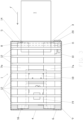
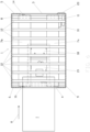
Figure 2 is a cross-section view through the line B-B ofFigure 1 ; -
Figure 3 is a cross-section view through the line A-A ofFigure 1 ; -
Figure 4 is an axonometric view of the device shown inFigure 1 , in a second operating mode; -
Figure 5 is a cross-section view through the line D-D ofFigure 4 ; and -
Figure 6 is a cross-section view through the line C-C ofFigure 4 . - With reference to accompanying drawings, a device for checking banknotes according to the invention has been indicated in its entirety with the
reference numeral 1. - The device for checking
banknotes 1 comprises anouter container 2 in which afirst opening 3 for inserting and extracting a banknote T and asecond opening 4 for inserting and extracting a banknote T are provided. - In particular, the
first opening 3 and thesecond opening 4 are formed, respectively, at afirst side 5 and asecond side 6 of theouter container 2, opposite to thefirst side 5. - According to the accompanying drawings, the
outer container 2 has a parallelepiped shape; however, according to further variants of the invention, it can also adopt shapes different from that shown in the drawings. - Inside the
outer container 2, between thefirst opening 3 and the second opening 4, there is a pair ofconveyor belts first shaft 8 and asecond shaft 9. - The
first shaft 8 and thesecond shaft 9 are also parallel to each other and mounted, respectively, at thefirst opening 3 and the second opening 4 in a rotatable manner about their respective axes. - For the movement of the
conveyor belts electric motor 10 of reduced power is provided connected to thefirst shaft 8 by means of aconnecting belt 11, so as to be able to rotate it about its axis in both directions of rotation, thus setting in motion the pair ofconveyor belts second opening 4, or in the other direction, that is, from the second opening 4 towards thefirst opening 3. - Above the
conveyor belts rollers 12 directed parallel to thefirst shaft 8 and to thesecond shaft 9 and idly rotatable about their respective axes, in such a way that the banknote T carried by theconveyor belts - The
aforesaid rollers 12 are evenly distributed over the entire length of theconveyor belts - A pressing system (not shown in the drawings) acting on the plurality of
rollers 12 can also be provided in the device for checkingbanknotes 1 in such a way as to push them, constantly, against theunderlying conveyor belts - According to further possible embodiments of the invention, not shown in the accompanying drawings, the
aforementioned conveyor belts rollers 12 can be replaced with other movement systems suitable to allow the transport of a banknote T from thefirst opening 3 to thesecond opening 4 and from thesecond opening 4 to thefirst opening 3. - A first pair of
presence sensors first opening 3, for detecting the insertion of a banknote T in thefirst opening 3. - In the specific case shown in the accompanying drawings, the two sensors of the first pair of
presence sensors first opening 3. - The first pair of
presence sensors electric motor 10, in such a way that when the pair ofpresence sensors first opening 3, theelectric motor 10 automatically comes into operation by advancing bothconveyor belts first opening 3 towards the second opening 4 (seeFigs. 1-3 ). - Similarly, a second pair of
presence sensors second opening 4 to detect the insertion of a banknote T in thesecond opening 4. - In the specific case shown in the accompanying drawings, the sensors of the second pair of
presence sensors second opening 4. - The second pair of
presence sensors electric motor 10, in such a way that when this pair ofpresence sensors second opening 4, theelectric motor 10 automatically comes into operation by advancing bothconveyor belts second opening 4 towards the first opening 3 (seeFigs. 4-6 ). - Inside the
outer container 2 there are also one ormore sensors conveyor belts first opening 3 to the second opening 4 (seeFigs. 1-3 ) or vice versa, that is, from the second opening 4 to the first opening 3 (seeFigs. 4-6 ). - Specifically, the aforementioned characteristics are characteristics that allow determination of whether each banknote T is genuine or counterfeit, and possibly also the value of the banknote T itself.
- The
aforementioned sensors - The
sensors - The
same sensors - The
aforementioned sensors outer container 2 in positions such as to be able to emit radiation, if provided for by their operation, on each banknote T that transits on theconveyor belts first opening 3 to thesecond opening 4 or from thesecond opening 4 to thefirst opening 3. - Since the
aforementioned sensors - Inside the
outer container 2 there is also anelectronic control board 19 for controlling and coordinating the operation of the first pair ofpresence sensors presence sensors electric motor 10 and of thesensors - For this reason, the first pair of
presence sensors presence sensors electric motor 10 and also thesensors electronic control board 19. - The same
electronic control board 19 also allows coordination of the operation of the first pair ofpresence sensors presence sensors presence sensors presence sensors banknote 1 or to the exit of the banknote T from the latter. - Specifically, when the banknote T is inserted into the
first opening 3 theelectronic control board 19 will command the activation of theelectric motor 10 so as to advance theconveyor belts electric motor 10 when the second pair ofpresence sensors Figs. 1-3 ). - Similarly, when the banknote T is inserted in the
second opening 4 theelectronic control board 19 will command the activation of theelectric motor 10 so as to advance theconveyor belts electric motor 10 when the first pair ofpresence sensors Figs. 4-6 ). - It follows therefore that the
electric motor 10 is left running only for the time necessary for the transport of each banknote T from thefirst opening 3 to thesecond opening 4 or vice versa; this means that theelectric motor 10 is not used more than necessary for the correct operation of the device for checking thebanknote 1, and in this way the operating life of theelectric motor 10 itself is possibly increased. - In the device for checking
banknotes 1 there is also provided aUSB socket 20, or other data transfer socket, operatively connected to theelectronic control board 19, to allow the transfer of data to and from said device for checkingbanknotes 1, including the updating of the relative control software. - The device for checking
banknotes 1 according to the invention may comprise, in a position visible on theouter container 2, adisplay 21 and/or a visual and/or audible indicator for visually and/or acoustically indicating whether the banknote T inserted in thefirst opening 3 or in thesecond opening 4 is genuine or counterfeit, and possibly also for visually indicating the value of the banknote T itself. - Alternatively or in addition to the
aforementioned displays 21 and visual and/or audible indicator, a socket (such as the aforementioned USB socket 20) and/or a wireless transceiver may be provided in the device for checkingbanknotes 1 to allow the cable or wireless connection to an external visual and/or audible indicator or display. - The device for checking
banknotes 1 further comprises an electrical power supply system (not shown) electrically connected to theelectronic control board 19 and an electrical connector (not shown) forming part of such an electrical power supply system and electrically connectable to an external electrical outlet (not shown) by means of an external cable (not shown). - According to a technical variant of the invention, not shown in the accompanying drawings, the aforementioned power supply system also includes one or more rechargeable batteries electrically connected both to the aforementioned electrical connector and to the
electronic control board 19, in such a way that the latter and also the aforementioned functional components electrically connected to theelectronic control board 19 can receive the power supply from said one or more rechargeable batteries even when the electrical connector is not connected to a power outlet. - According to the operation of the device for checking
banknotes 1, when a banknote T is inserted into thefirst opening 3, the first pair ofpresence sensors electronic control board 19, which automatically provides for the activation of theelectric motor 10 in such a way as to advance theconveyor belts Figs. 1-3 ). - During the passage of the banknote T from the
first opening 3 to thesecond opening 4, theaforementioned sensors - Subsequently, when the same banknote T arrives at the
second opening 4, the second pair ofpresence sensors electronic control board 19, which in turn automatically deactivates theelectric motor 10 and then stops the advancement of theconveyor belts - Similarly, when inserting a banknote T into the
second opening 4, the second pair ofpresence sensors electronic control board 19, which automatically commands the activation of theelectric motor 10 in such a way as to advance theconveyor belts Figs. 4-6 ). - During the passage of the banknote T from the
second opening 4 to thefirst opening 3, theaforementioned sensors - Subsequently, when the same banknote T arrives at the
first opening 3, the first pair ofpresence sensors electronic control board 19, which in turn automatically deactivates theelectric motor 10 and then stops the advancement of theconveyor belts - According to a further embodiment of the invention not shown in the accompanying drawings, the
electronic control board 19 can be configured in such a way that the exit of the banknote T, following the checking by thesensors same opening - Again according to this latter embodiment, the
electronic control board 19 can be programmed in such a way that if theaforementioned sensors same opening conveyor belts - As can be seen from the description above, the device for checking
banknotes 1 is, in addition to being effective in detecting the authenticity (and possibly also the value) of the banknotes T, also particularly convenient and useful for carrying out payment operations in the cash registers of commercial establishments, to ensure the authenticity of the banknotes delivered by the customer to the cashier for the execution of the payment, and of the banknotes delivered by the cashier to the customer for the possible change of the sum paid. - In fact, thanks to the two-way operation of the device for checking
banknotes 1 described above, the customer will be able to insert, for example, the banknotes T in thefirst opening 3, thus allowing the cashier to withdraw them from thesecond opening 4, after checking the authenticity by the same device for checkingbanknotes 1. - The cashier, in case of return of change, will be able to insert the banknotes in the
second opening 4 facing him/her, thus allowing the customer to withdraw them from thefirst opening 3, after checking the authenticity by the same device for checkingbanknotes 1. - It is understood that the above has been described by way of non-limiting example, so that any construction variations should be considered as falling within the scope of the present technical solution, as described above and claimed below.
Claims (7)
- Device for checking banknotes (1) which comprises:- a container (2) where are defined a first opening (3) for inserting at least one banknote (T) and a second opening (4) for inserting at least one banknote (T);- moving means (7a, 7b, 8, 9, 10, 11, 12) for carrying, in use, at least one banknote (T), which is inserted in the first opening (3), to an operative zone placed in the container (2) and from said operative zone to the second opening (4) or to the first opening (3), and for carrying, in use, at least one banknote (T), which is inserted in the second opening (4), to said operative zone and from said operative zone to the first opening (3) or to the second opening (4);- first sensor means (17, 18) for detecting at least one characteristic of the at least one banknote (T) in said operative zone and for ascertaining the value of said at least one banknote (T) and/or whether said at least one banknote (T) is genuine or counterfeit, based on said at least one characteristic;- second sensor means (13, 14) for detecting the insertion of at least one banknote (T) in the first opening (3); and- third sensor means (15, 16) for detecting the insertion of at least one banknote (T) in the second opening (4);wherein the second sensor means (13, 14) are configured to also detect the at least partial exiting of at least one banknote (T) from the first opening (3), and the third sensor means (15, 16) are configured to also detect the at least partial exiting of at least one banknote (T) from the second opening (4); andwherein the moving means (7a, 7b, 8, 9, 10, 11, 12) are operatively connected with the second sensor means (13, 14) and with the third sensor means (15, 16) such that the stopping of the moving means (7a, 7b, 8, 9, 10, 11, 12) is automatically executed when said at least one banknote (T) being transported by the moving means (7a, 7b, 8, 9, 10, 11, 12) reaches the first opening (3) or the second opening (4).
- Device for checking banknotes (1) according to claim 1, characterized in that the first opening (3) is formed at a first side (5) of the container (2) and in that the second opening (4) is formed at a second side (6) of the container (2), wherein said first side (5) and second side (6) are opposite each other.
- Device for checking banknotes (1) according to claim 1 or 2, characterized in that the moving means (7a, 7b, 8, 9, 10, 11, 12) are operatively connected with the second sensor means (13, 14) and the third sensor means (15, 16) such that the moving of said banknote (T) from the first opening (3) to said operative zone and from said operative zone to the second opening (4) or to the first opening (3) by the moving means (7a, 7b, 8, 9, 10, 11, 12) is automatically executed when a banknote (T) is inserted in the first opening (3), and such that the moving of said banknote (T) from the second opening (4) to said operative zone and from said operative zone to the first opening (3) or to the second opening (4) by the moving means (7a, 7b, 8, 9, 10, 11, 12) is automatically executed when a banknote (T) is inserted in the second opening (4).
- Device for checking banknotes (1) according to any one of preceding claims, characterized in that the second sensor means (13, 14) or the third sensor means (15, 16) comprise at least one presence sensor.
- Device for checking banknotes (1) according to any one of preceding claims, characterized in that the first sensor means (17, 18) comprise at least one magnetic sensor, and/or at least one sensor using ultraviolet rays or infrared rays or white light, and/or at least one sensor using electromagnetic radiations with different wavelengths, and/or at least one device for detecting at least one size of the banknote (T).
- Device for checking banknotes (1) according to any one of preceding claims, characterized in that it comprises a display (21) and/or a visual and/or acoustic indicator for visually and/or acoustically indicating whether said banknote (T) is genuine or counterfeit, and/or for visually indicating the value of said banknote (T).
- Device for checking banknotes (1) according to any one of preceding claims, characterized in that it comprises a socket and/or a wireless transceiver to allow, in use, a cable and/or wireless connection with an external display or with an external visual and/or acoustic indicator for visually and/or acoustically indicating whether said banknote (T) is genuine or counterfeit, and/or for visually indicating the value of said banknote (T).
Applications Claiming Priority (2)
| Application Number | Priority Date | Filing Date | Title |
|---|---|---|---|
| IT102022000010955A IT202200010955A1 (en) | 2022-05-25 | 2022-05-25 | IMPROVED BANKNOTE VERIFICATION DEVICE |
| IT202022000002132U IT202200002132U1 (en) | 2022-05-25 | 2022-05-25 | IMPROVED BANKNOTE VERIFICATION DEVICE |
Publications (1)
| Publication Number | Publication Date |
|---|---|
| EP4283580A1 true EP4283580A1 (en) | 2023-11-29 |
Family
ID=88506074
Family Applications (1)
| Application Number | Title | Priority Date | Filing Date |
|---|---|---|---|
| EP23020242.6A Pending EP4283580A1 (en) | 2022-05-25 | 2023-05-23 | Improved device for checking banknotes |
Country Status (1)
| Country | Link |
|---|---|
| EP (1) | EP4283580A1 (en) |
Citations (4)
| Publication number | Priority date | Publication date | Assignee | Title |
|---|---|---|---|---|
| JP2004133735A (en) * | 2002-10-11 | 2004-04-30 | World Techno:Kk | Checker for printed paper sheet |
| JP2008052486A (en) * | 2006-08-24 | 2008-03-06 | Oki Electric Ind Co Ltd | Automatic transaction apparatus |
| US20100289211A1 (en) * | 2008-01-11 | 2010-11-18 | Universal Entertainment Corporation | Paper sheet treating apparatus |
| WO2022070017A1 (en) * | 2020-10-02 | 2022-04-07 | Roberto Serpilli | Device for sanitizing banknotes |
-
2023
- 2023-05-23 EP EP23020242.6A patent/EP4283580A1/en active Pending
Patent Citations (4)
| Publication number | Priority date | Publication date | Assignee | Title |
|---|---|---|---|---|
| JP2004133735A (en) * | 2002-10-11 | 2004-04-30 | World Techno:Kk | Checker for printed paper sheet |
| JP2008052486A (en) * | 2006-08-24 | 2008-03-06 | Oki Electric Ind Co Ltd | Automatic transaction apparatus |
| US20100289211A1 (en) * | 2008-01-11 | 2010-11-18 | Universal Entertainment Corporation | Paper sheet treating apparatus |
| WO2022070017A1 (en) * | 2020-10-02 | 2022-04-07 | Roberto Serpilli | Device for sanitizing banknotes |
Similar Documents
| Publication | Publication Date | Title |
|---|---|---|
| KR970005399B1 (en) | Paper money processor | |
| US8854186B2 (en) | Sheet-of-paper processing device | |
| CN100530251C (en) | Device for storing banknote | |
| US8313100B2 (en) | Paper sheet processing apparatus with redetection process and method of conveying paper sheet | |
| US5513773A (en) | Single denomination bill dispensing apparatus | |
| US8973730B2 (en) | Bank notes handling apparatus | |
| EP1997079B1 (en) | Banknote acceptor with visual checking | |
| US7230223B2 (en) | Sensing system for ascertaining currency content of ATM | |
| US8873828B2 (en) | Device for processing paper sheets or the like | |
| US20110006475A1 (en) | Paper treating apparatus | |
| US20110128122A1 (en) | Paper sheet processing apparatus | |
| EP4283581A1 (en) | Enhanced device for checking banknotes | |
| KR101166603B1 (en) | Forgery tester paper money of a counting machine using dual uv sensor | |
| EP4283579A1 (en) | Device for checking coins and banknotes | |
| IT202200002132U1 (en) | IMPROVED BANKNOTE VERIFICATION DEVICE | |
| IT202200002123U1 (en) | IMPROVED BANKNOTE VERIFICATION DEVICE | |
| IT202200002129U1 (en) | IMPROVED BANKNOTE VERIFICATION DEVICE | |
| KR200399249Y1 (en) | Paper money counting apparatus having function of discriminating counterfeit note | |
| JP5081873B2 (en) | Coin deposit / withdrawal device | |
| CN209388400U (en) | A banknote checking machine | |
| EP3291186B1 (en) | A bank note handling machine | |
| KR100576035B1 (en) | Paper thickness detection device and method | |
| IT202200002156U1 (en) | IMPROVED BANKNOTE VERIFICATION DEVICE | |
| KR20070045450A (en) | Banknote counter | |
| JP3393624B2 (en) | Banknote handling equipment |
Legal Events
| Date | Code | Title | Description |
|---|---|---|---|
| PUAI | Public reference made under article 153(3) epc to a published international application that has entered the european phase |
Free format text: ORIGINAL CODE: 0009012 |
|
| STAA | Information on the status of an ep patent application or granted ep patent |
Free format text: STATUS: THE APPLICATION HAS BEEN PUBLISHED |
|
| AK | Designated contracting states |
Kind code of ref document: A1 Designated state(s): AL AT BE BG CH CY CZ DE DK EE ES FI FR GB GR HR HU IE IS IT LI LT LU LV MC ME MK MT NL NO PL PT RO RS SE SI SK SM TR |
|
| STAA | Information on the status of an ep patent application or granted ep patent |
Free format text: STATUS: REQUEST FOR EXAMINATION WAS MADE |
|
| 17P | Request for examination filed |
Effective date: 20240527 |
|
| RBV | Designated contracting states (corrected) |
Designated state(s): AL AT BE BG CH CY CZ DE DK EE ES FI FR GB GR HR HU IE IS IT LI LT LU LV MC ME MK MT NL NO PL PT RO RS SE SI SK SM TR |
|
| STAA | Information on the status of an ep patent application or granted ep patent |
Free format text: STATUS: EXAMINATION IS IN PROGRESS |
|
| 17Q | First examination report despatched |
Effective date: 20240829 |