EP4283329A1 - Vorrichtung und verfahren zur gemeinsamen erfassung einer farbe und eines abstands eines gegenstands - Google Patents
Vorrichtung und verfahren zur gemeinsamen erfassung einer farbe und eines abstands eines gegenstands Download PDFInfo
- Publication number
- EP4283329A1 EP4283329A1 EP22175219.9A EP22175219A EP4283329A1 EP 4283329 A1 EP4283329 A1 EP 4283329A1 EP 22175219 A EP22175219 A EP 22175219A EP 4283329 A1 EP4283329 A1 EP 4283329A1
- Authority
- EP
- European Patent Office
- Prior art keywords
- light
- optics
- designed
- receiving
- distance
- Prior art date
- Legal status (The legal status is an assumption and is not a legal conclusion. Google has not performed a legal analysis and makes no representation as to the accuracy of the status listed.)
- Granted
Links
Images




Classifications
-
- G—PHYSICS
- G01—MEASURING; TESTING
- G01J—MEASUREMENT OF INTENSITY, VELOCITY, SPECTRAL CONTENT, POLARISATION, PHASE OR PULSE CHARACTERISTICS OF INFRARED, VISIBLE OR ULTRAVIOLET LIGHT; COLORIMETRY; RADIATION PYROMETRY
- G01J3/00—Spectrometry; Spectrophotometry; Monochromators; Measuring colours
- G01J3/46—Measurement of colour; Colour measuring devices, e.g. colorimeters
- G01J3/50—Measurement of colour; Colour measuring devices, e.g. colorimeters using electric radiation detectors
- G01J3/502—Measurement of colour; Colour measuring devices, e.g. colorimeters using electric radiation detectors using a dispersive element, e.g. grating, prism
-
- G—PHYSICS
- G01—MEASURING; TESTING
- G01N—INVESTIGATING OR ANALYSING MATERIALS BY DETERMINING THEIR CHEMICAL OR PHYSICAL PROPERTIES
- G01N21/00—Investigating or analysing materials by the use of optical means, i.e. using sub-millimetre waves, infrared, visible or ultraviolet light
- G01N21/17—Systems in which incident light is modified in accordance with the properties of the material investigated
- G01N21/25—Colour; Spectral properties, i.e. comparison of effect of material on the light at two or more different wavelengths or wavelength bands
- G01N21/255—Details, e.g. use of specially adapted sources, lighting or optical systems
-
- G—PHYSICS
- G01—MEASURING; TESTING
- G01S—RADIO DIRECTION-FINDING; RADIO NAVIGATION; DETERMINING DISTANCE OR VELOCITY BY USE OF RADIO WAVES; LOCATING OR PRESENCE-DETECTING BY USE OF THE REFLECTION OR RERADIATION OF RADIO WAVES; ANALOGOUS ARRANGEMENTS USING OTHER WAVES
- G01S17/00—Systems using the reflection or reradiation of electromagnetic waves other than radio waves, e.g. lidar systems
- G01S17/02—Systems using the reflection of electromagnetic waves other than radio waves
- G01S17/06—Systems determining position data of a target
- G01S17/42—Simultaneous measurement of distance and other co-ordinates
-
- G—PHYSICS
- G01—MEASURING; TESTING
- G01J—MEASUREMENT OF INTENSITY, VELOCITY, SPECTRAL CONTENT, POLARISATION, PHASE OR PULSE CHARACTERISTICS OF INFRARED, VISIBLE OR ULTRAVIOLET LIGHT; COLORIMETRY; RADIATION PYROMETRY
- G01J3/00—Spectrometry; Spectrophotometry; Monochromators; Measuring colours
- G01J3/02—Details
- G01J3/0205—Optical elements not provided otherwise, e.g. optical manifolds, diffusers, windows
- G01J3/0208—Optical elements not provided otherwise, e.g. optical manifolds, diffusers, windows using focussing or collimating elements, e.g. lenses or mirrors; performing aberration correction
-
- G—PHYSICS
- G01—MEASURING; TESTING
- G01J—MEASUREMENT OF INTENSITY, VELOCITY, SPECTRAL CONTENT, POLARISATION, PHASE OR PULSE CHARACTERISTICS OF INFRARED, VISIBLE OR ULTRAVIOLET LIGHT; COLORIMETRY; RADIATION PYROMETRY
- G01J3/00—Spectrometry; Spectrophotometry; Monochromators; Measuring colours
- G01J3/02—Details
- G01J3/10—Arrangements of light sources specially adapted for spectrometry or colorimetry
-
- G—PHYSICS
- G01—MEASURING; TESTING
- G01J—MEASUREMENT OF INTENSITY, VELOCITY, SPECTRAL CONTENT, POLARISATION, PHASE OR PULSE CHARACTERISTICS OF INFRARED, VISIBLE OR ULTRAVIOLET LIGHT; COLORIMETRY; RADIATION PYROMETRY
- G01J3/00—Spectrometry; Spectrophotometry; Monochromators; Measuring colours
- G01J3/12—Generating the spectrum; Monochromators
- G01J3/14—Generating the spectrum; Monochromators using refracting elements, e.g. prisms
-
- G—PHYSICS
- G01—MEASURING; TESTING
- G01S—RADIO DIRECTION-FINDING; RADIO NAVIGATION; DETERMINING DISTANCE OR VELOCITY BY USE OF RADIO WAVES; LOCATING OR PRESENCE-DETECTING BY USE OF THE REFLECTION OR RERADIATION OF RADIO WAVES; ANALOGOUS ARRANGEMENTS USING OTHER WAVES
- G01S17/00—Systems using the reflection or reradiation of electromagnetic waves other than radio waves, e.g. lidar systems
- G01S17/02—Systems using the reflection of electromagnetic waves other than radio waves
- G01S17/06—Systems determining position data of a target
- G01S17/08—Systems determining position data of a target for measuring distance only
-
- G—PHYSICS
- G01—MEASURING; TESTING
- G01S—RADIO DIRECTION-FINDING; RADIO NAVIGATION; DETERMINING DISTANCE OR VELOCITY BY USE OF RADIO WAVES; LOCATING OR PRESENCE-DETECTING BY USE OF THE REFLECTION OR RERADIATION OF RADIO WAVES; ANALOGOUS ARRANGEMENTS USING OTHER WAVES
- G01S17/00—Systems using the reflection or reradiation of electromagnetic waves other than radio waves, e.g. lidar systems
- G01S17/02—Systems using the reflection of electromagnetic waves other than radio waves
- G01S17/06—Systems determining position data of a target
- G01S17/08—Systems determining position data of a target for measuring distance only
- G01S17/32—Systems determining position data of a target for measuring distance only using transmission of continuous waves, whether amplitude-, frequency-, or phase-modulated, or unmodulated
-
- G—PHYSICS
- G01—MEASURING; TESTING
- G01S—RADIO DIRECTION-FINDING; RADIO NAVIGATION; DETERMINING DISTANCE OR VELOCITY BY USE OF RADIO WAVES; LOCATING OR PRESENCE-DETECTING BY USE OF THE REFLECTION OR RERADIATION OF RADIO WAVES; ANALOGOUS ARRANGEMENTS USING OTHER WAVES
- G01S17/00—Systems using the reflection or reradiation of electromagnetic waves other than radio waves, e.g. lidar systems
- G01S17/86—Combinations of lidar systems with systems other than lidar, radar or sonar, e.g. with direction finders
-
- G—PHYSICS
- G01—MEASURING; TESTING
- G01S—RADIO DIRECTION-FINDING; RADIO NAVIGATION; DETERMINING DISTANCE OR VELOCITY BY USE OF RADIO WAVES; LOCATING OR PRESENCE-DETECTING BY USE OF THE REFLECTION OR RERADIATION OF RADIO WAVES; ANALOGOUS ARRANGEMENTS USING OTHER WAVES
- G01S7/00—Details of systems according to groups G01S13/00, G01S15/00, G01S17/00
- G01S7/48—Details of systems according to groups G01S13/00, G01S15/00, G01S17/00 of systems according to group G01S17/00
- G01S7/4802—Details of systems according to groups G01S13/00, G01S15/00, G01S17/00 of systems according to group G01S17/00 using analysis of echo signal for target characterisation; Target signature; Target cross-section
-
- G—PHYSICS
- G01—MEASURING; TESTING
- G01S—RADIO DIRECTION-FINDING; RADIO NAVIGATION; DETERMINING DISTANCE OR VELOCITY BY USE OF RADIO WAVES; LOCATING OR PRESENCE-DETECTING BY USE OF THE REFLECTION OR RERADIATION OF RADIO WAVES; ANALOGOUS ARRANGEMENTS USING OTHER WAVES
- G01S7/00—Details of systems according to groups G01S13/00, G01S15/00, G01S17/00
- G01S7/48—Details of systems according to groups G01S13/00, G01S15/00, G01S17/00 of systems according to group G01S17/00
- G01S7/4808—Evaluating distance, position or velocity data
-
- G—PHYSICS
- G01—MEASURING; TESTING
- G01S—RADIO DIRECTION-FINDING; RADIO NAVIGATION; DETERMINING DISTANCE OR VELOCITY BY USE OF RADIO WAVES; LOCATING OR PRESENCE-DETECTING BY USE OF THE REFLECTION OR RERADIATION OF RADIO WAVES; ANALOGOUS ARRANGEMENTS USING OTHER WAVES
- G01S7/00—Details of systems according to groups G01S13/00, G01S15/00, G01S17/00
- G01S7/48—Details of systems according to groups G01S13/00, G01S15/00, G01S17/00 of systems according to group G01S17/00
- G01S7/481—Constructional features, e.g. arrangements of optical elements
- G01S7/4814—Constructional features, e.g. arrangements of optical elements of transmitters alone
- G01S7/4815—Constructional features, e.g. arrangements of optical elements of transmitters alone using multiple transmitters
-
- G—PHYSICS
- G02—OPTICS
- G02B—OPTICAL ELEMENTS, SYSTEMS OR APPARATUS
- G02B27/00—Optical systems or apparatus not provided for by any of the groups G02B1/00 - G02B26/00, G02B30/00
- G02B27/10—Beam splitting or combining systems
- G02B27/14—Beam splitting or combining systems operating by reflection only
- G02B27/141—Beam splitting or combining systems operating by reflection only using dichroic mirrors
-
- G—PHYSICS
- G01—MEASURING; TESTING
- G01J—MEASUREMENT OF INTENSITY, VELOCITY, SPECTRAL CONTENT, POLARISATION, PHASE OR PULSE CHARACTERISTICS OF INFRARED, VISIBLE OR ULTRAVIOLET LIGHT; COLORIMETRY; RADIATION PYROMETRY
- G01J3/00—Spectrometry; Spectrophotometry; Monochromators; Measuring colours
- G01J3/02—Details
- G01J3/10—Arrangements of light sources specially adapted for spectrometry or colorimetry
- G01J2003/102—Plural sources
-
- G—PHYSICS
- G01—MEASURING; TESTING
- G01S—RADIO DIRECTION-FINDING; RADIO NAVIGATION; DETERMINING DISTANCE OR VELOCITY BY USE OF RADIO WAVES; LOCATING OR PRESENCE-DETECTING BY USE OF THE REFLECTION OR RERADIATION OF RADIO WAVES; ANALOGOUS ARRANGEMENTS USING OTHER WAVES
- G01S17/00—Systems using the reflection or reradiation of electromagnetic waves other than radio waves, e.g. lidar systems
- G01S17/02—Systems using the reflection of electromagnetic waves other than radio waves
- G01S17/06—Systems determining position data of a target
- G01S17/46—Indirect determination of position data
Definitions
- the invention relates to a device and a method for jointly detecting a color and a distance of an object.
- Devices and methods that are designed to recognize a color or a distance of an object are known in principle. Particularly when determining a color, it is desirable to also know the distance of the object, since the determined color values change depending on the distance of the object and thus also the color resolution.
- the transmitting unit includes a light element that is designed to emit light in a predefined wavelength range and a transmitting optics that is designed to direct the emitted light onto an object.
- the receiving unit comprises a first receiving element, a second receiving element, which is arranged at a distance from the first receiving element, and receiving optics which are designed to receive light remitted by the object and to direct it onto the first receiving element and the second receiving element.
- the evaluation unit is designed to evaluate light received by the first receiving element and to determine a distance of the object and from it evaluate the light received by the second receiving element and determine a color of the object.
- the light element is designed to emit light in a predefined wavelength range, in particular in the range of visible light.
- the light element is in particular designed to emit chromatically broadband, so-called white light.
- the transmitting optics direct the emitted light towards an object whose color is to be recognized.
- One or more lenses and/or one or more mirrors can be used for this purpose.
- the light is remitted by the object and directed onto a first and a second receiving element using the receiving optics, which can also have one or more lenses and/or one or more mirrors.
- the first receiving element is designed to return distance information and is designed, for example, as a line sensor. Alternatively, the first receiving element can also be designed as a time-of-flight sensor.
- the second receiving element is designed to return color information and is designed, for example, as a color sensor. In particular, the second receiving element is designed to detect different color components in the light remitted by the object, for example by a so-called CCD sensor.
- the evaluation unit then evaluates the information received from the first and second receiving elements and thus determines a distance and a color.
- a single light element is used to emit light that is used both for distance detection and for color detection is used. This results in a particularly compact and inexpensive structure of the device.
- the light element has a first light source, a second light source and a third light source, which are spaced apart from one another and which are designed to emit light in three different predefined wave ranges, the transmitting unit further having superposition optics which is designed to superimpose the light emitted by the three light sources and to direct it onto a common beam axis.
- the first, two and third light sources are designed in particular as semiconductor light sources, in particular light-emitting diodes.
- the first, second and third wavelength ranges lie in particular in the spectrum of visible light.
- the three wavelength ranges are red, green and blue.
- the three wavelength ranges differ, but can partially overlap. This is in particular an alternative embodiment to the embodiment described above, in which the light element comprises a single light source which is designed to emit chromatically broadband, so-called white light.
- the first, second and third light sources can be activated one after the other in this embodiment, so that a specific emission pattern results from the three wavelength ranges.
- the second receiving element can be designed such that it can, in particular, only determine the intensity of the remitted light and the evaluation unit determines the color of the object on the basis of this intensity, in particular taking the emission pattern into account.
- This embodiment enables particularly good color recognition.
- the overlay optics comprise a reflector which has a plurality of reflecting surfaces which are arranged and designed to superimpose the light emitted by the three light sources and to direct it onto a common beam axis.
- This embodiment of the overlay optics is, for example, in the EP 3 770 567 B1 described.
- an alternative embodiment of the device provides that the overlay optics have two dichroic mirrors, which are arranged and designed to superimpose the light emitted by the three light sources and to direct it onto a common beam axis.
- This embodiment of the overlay optics can also be referred to as a beam splitter staircase.
- a further alternative embodiment of the device provides that the overlay optics comprise a first prism, a second prism, a third prism and a fourth prism, which are arranged next to one another in such a way that they together have a cuboid shape, with contact surfaces between the prisms being dichroitically coated .
- this embodiment provides that the first, second, third and fourth prisms are cemented and/or glued together, in particular on respective surfaces that extend from one of the legs of the triangle on which a prism is based.
- One embodiment of the device provides that it further comprises a base element that is flexible in sections, on which the first light source, the second light source and the third light source are arranged, the base element being arranged around the superposition optics in such a way that one light source is at one of them is arranged on three adjacent side surfaces of the overlay optics.
- This embodiment makes it possible to mount the first, second and third light sources in a particularly simple manner.
- the base element has a first positioning element, a second positioning element and a third positioning element, which fasten the first light source, the second light source and the third light source at a predefined distance from the three adjacent side surfaces of the overlay optics.
- the first, second and third positioning elements fasten the first, second and third light sources each in a width, a length and a height, i.e. in x, y and z in space, relative to the three adjacent side surfaces of the overlay optics.
- the first light source, the second light source and the third light source have an aperture, the predefined distance being in particular a direct contact, more particularly a gap-free contact, of the respective aperture with the respective side surface of the overlay optics.
- a respective aperture can be provided between the positioning element and the respective side surface.
- This embodiment ensures a particularly precise positioning of the light sources in relation to the overlay optics.
- the base element further has a fourth positioning element, and wherein the first positioning element, the second positioning element, the third positioning element and the fourth positioning element attach the overlay optics to four adjacent side surfaces.
- This embodiment enables a particularly secure attachment of the overlay optics.
- the fourth positioning element has a diaphragm which is designed to spatially limit the light superimposed by the superposition optics.
- This embodiment makes it possible to adjust the size and shape of the light spot on the object.
- the fourth positioning element fastens the panel at a predefined distance from the fourth side surface.
- the fourth positioning element fastens the aperture in a width, a length and a height, i.e. in x, y and z in space, relative to the fourth side surfaces of the overlay optics.
- the predefined distance is a direct contact, more particularly a gap-free contact.
- This embodiment enables a particularly precise overlay.
- the first positioning element, the second positioning element and the third positioning element each have an upper and a lower holding element that are formed attach the overlay optics to an upper surface and a lower surface. With the help of these holding elements, the positioning of the first, second and third light sources can be ensured in particular relative to the overlay optics and/or the respective aperture.
- This embodiment ensures a particularly secure attachment of the overlay optics.
- One embodiment of the device provides that the evaluation unit is designed to correct the determined color based on the determined distance of the object.
- the distance to the object is determined regularly, for example at 1 kHz, which enables high-frequency compensation of the color values.
- the correction of the determined color is carried out in particular using a function stored in the evaluation unit, which is stored individually for each color and matching the second receiving element during production.
- the evaluation unit determines the distance of the object using triangulation based on the light spot position on the line sensor and uses this to determine compensation or correction factors for the color determined by the second receiving element. This correction factor is multiplied accordingly by the signals from the second receiving element in order to compensate for the object distance in the height of the measurement signal.
- the detected measurement signal can change by several orders of magnitude. Since the resolvability of color differences depends primarily on the difference in the recorded measurement signal, the resolvability of color differences also changes with different object distances.
- the Electrical amplification of the measurement signal of the second receiving element is dynamically adjusted depending on the height of the measurement signal and thus also the distance of the object. Accordingly, the electrical amplification is increased at large distances and low signal heights and reduced at small distances and intense signals.
- the color resolution set in the evaluation unit and usable for the application is adjusted according to the set electrical gain and the determined distance correction factor. It can therefore be adjusted depending on the application conditions
- This embodiment enables particularly accurate color determination.
- the receiving optics are designed in one piece.
- “in one piece” means made of a coherent material and can also be referred to as integral.
- This embodiment enables a particularly compact structure of the device.
- the task mentioned at the beginning is also solved by a method for jointly detecting a color and a distance of an object.
- the method includes emitting light in a predefined wavelength range, directing the emitted light at an object, receiving light remitted from the object, directing the remitted light at a first receiving element and a second receiving element, evaluating the light remitted by the object first receiving element to determine a distance of the object and to evaluate the light received from the second Receiving element received light to determine a color of the object.
- a device for attaching an overlay optics comprises a sectionally flexible base element, and a first, second and third positioning element, which are arranged on the flexible base element, wherein the sectionally flexible base element is bendable such that the first positioning element with the second positioning element and the second positioning element with the third positioning element can be brought into engagement and thus forms a cavity in which overlay optics can be arranged.
- the device also includes a fourth positioning element that is engageable with the first and third positioning elements, thereby securing the overlay optics to the device.
- a method for attaching an overlay optics includes the steps of providing a device for attaching an overlay optics, comprising a partially flexible base element and a first, second and third positioning element arranged thereon; Bending the sectionally flexible base element; in Engaging the first positioning element with the second positioning element; engaging the second positioning member with the third positioning member; arranging overlay optics within a cavity created by engagement of the first, second and third positioning elements; engaging a fourth positioning element with the first and third positioning elements and thus attaching the overlay optics.
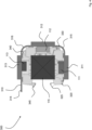
- Fig. 1 shows a schematic top view of a device 10 for jointly detecting a color and a distance of an object.
- the device 10 has a transmitting unit 100, a receiving unit 200 and an evaluation unit, which is not shown for reasons of clarity.
- the transmitting unit 100 includes a light element 110.
- the light element 110 includes a first light source 111, a second light source 112 and a third light source 113, each of which is spaced apart from one another.
- the first light source 111 is designed to emit light in a first predefined wave range
- the second light source 112 is designed to emit light in a second predefined wave range
- the third light source 112 is designed to emit light in a third predefined wave range.
- the first wave range, the second wave range and the third wave range differ, but can partially overlap.
- the transmitting unit 100 also includes superposition optics which are designed to superimpose the light emitted by the three light sources 111, 112, 113 and direct it onto a common beam axis.
- the overlay optics are shown here as an example as a beam overlay cube 115.
- the beam superimposition cube consists of four prisms attached to each other, which are dichroitically coated on the contact surfaces.
- the beam overlay cube has four rectangular side surfaces of the same size, arranged at right angles to one another, as well as a rectangular roof and a floor surface, which are also arranged at right angles to the side surfaces and either one Have the same size as the side surfaces or a different size.
- the term cube also includes cuboids.
- the three light sources 111, 112, 113 are arranged around the sides of the beam overlay cube 115 in such a way that a beam direction of the light emitted by the first light source 111 is offset by 90 degrees in the plane of the drawing to a beam direction of the light emitted by the second light source 112 and a beam direction of the light emitted by the second light source 112 is offset by 90 degrees in the plane of the drawing to a beam direction of the light emitted by the third light source 113, so the first light source 111 and the third light source 113 face each other by 180 degrees in the plane of the drawing.
- the beam overlay cube 115 is arranged and designed in such a way that the three beam directions of the three light sources are directed and superimposed in such a way that a common light beam is emitted from the beam overlay cube 115 opposite the second light source 112.
- the device 10 can also include a device for attaching an overlay optics, which is described below Fig. 2 will be described in more detail.
- superposition optics such as a reflector that has a plurality of reflecting surfaces or two dichroic mirrors, which are also designed to superimpose the light emitted by the three light sources and to direct it onto a common beam axis, which, however, are not shown in the figures shown are also possible.
- the transmitting unit 100 also includes a deflection optics 120, which is designed to deflect the light emitted by the three light sources 111, 112, 113 and superimposed by the superposition optics and to deflect it onto a transmitting optics 130.
- the transmission optics are designed by the three light sources 111, 112, 113 to direct emitted light at an object. The object is not shown for reasons of clarity and is located to the right of the device 10, outside the drawing area.
- the device 10 also includes a front window 250 through which the light emitted by the three light sources 111, 112, 113 exits the device, which is shown by the beam path 1. The emitted light is then remitted at the object, which is shown by the beam path 2, and enters the device 10 again as remitted light through the front window 250.
- the remitted light hits a receiving optics 230 of the receiving unit 200, which directs the remitted light onto a first receiving element 210 on the one hand and onto a second receiving element 220 on the other hand, which is spaced from the first receiving element 210.
- the first receiving element 210 and the second receiving element 220 are designed to receive the light directed at them and convert it into an electrical signal.
- the evaluation unit is designed to evaluate the light received by the first receiving element 210 or the electrical signal formed therefrom and to determine a distance of the object.
- the evaluation unit is also designed to evaluate the light received by the second receiving element 220 or the electrical signal formed therefrom and to determine a color of the object.
- Both the transmitting unit 100 with all of its described components and the receiving unit 200 with all of its described components are housed in a single housing, not shown for reasons of clarity, which has the front window 250 as the only optical interface.
- the evaluation unit can be arranged either in the housing or outside of it.
- the device uses 10 for joint detection a color and a distance of an object, a single light element 110 comprising three, in particular exactly three, light sources that are used both to determine a color and to determine a distance of the object.
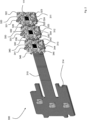
- Fig. 2 shows a perspective view of a device 300, which is used to attach an overlay optics, in particular an overlay optics as in Fig. 1 pictured.
- the device 300 is located as in Fig. 2 shown in a partial step of a method for attaching an overlay optics, which will be discussed in more detail in connection with Fig. 10 is described.
- the device 300 for attaching an overlay optics comprises a sectionally flexible base element 310, comprising a first rigid section 311, a second rigid section 312, a third rigid section 313 and a fourth rigid section 314.
- a first positioning element 320 is arranged on the first rigid section 311, a second positioning element 330 is arranged on the second rigid section 312 and a third positioning element 340 is arranged on the third rigid section 313.
- the first positioning element 320, the second positioning element 330 and the third positioning element 340 are essentially uniform, with each of the positioning elements having a plurality of holding elements and a plurality of locking elements, which are described below.
- the first positioning element 320 has an upper holding element 321, a lower holding element 324 and four side locking elements 322, 323, 325 and 326.
- the second positioning element 330 has an upper holding element 331, a lower holding element 334 and four side ones Locking elements 332, 333, 335 and 336.
- the third positioning element 340 also has an upper holding element 341, a lower holding element 344 and four side locking elements 342, 343, 345 and 346.
- the two left side locking elements 322 and 323, 332 and 333 as well as 342 and 343 are arranged offset outwards from the corresponding two right side locking elements 325 and 326, 335 and 336 as well as 345 and 346.
- the locking elements are arranged in such a way that they can engage with corresponding grooves in the respectively adjacent positioning element and can thus fasten the positioning elements to one another.
- a light source is arranged centrally in each of the three positioning elements 320, 330, 340, with only the first light source 111 in the first positioning element 320 being provided with a reference number.
- Each of the three light sources is provided with a diaphragm, which is also not shown for reasons of clarity.
- the first positioning element 320, the second positioning element 330 and the third positioning element 340 are fastened on the partially flexible base element 310 in the SMD process.
- a first flexible section is arranged between the first rigid section 311 and the second rigid section 312 and a second flexible section is arranged between the second rigid section 312 and the third rigid section 313, the rigid sections 315 and 316 not being present for reasons of clarity are provided with a reference number.
- the base element 310 can also have further flexible sections, which are not provided with reference numbers in detail here.
- the fourth rigid section 314 further has fastening and/or connection elements for fastening and/or connecting the device 300 to a housing of a device 10 for jointly detecting a color and a distance of an object, as in Fig. 1 shown, which are not provided with reference numbers for reasons of clarity.
- Fig. 3 shows a perspective view of a device 300 for attaching an overlay optics as in Fig. 2 shown.
- the device 300 is located as in Fig. 3 shown in a further sub-step of a method for attaching an overlay optics, which will be discussed in more detail in connection with Fig. 10 is described.
- the beam overlay cube 115 has a substantially cuboid shape and is composed of four prisms.
- the three rigid sections 311, 312, 313 with the positioning elements 320, 330, 340 arranged thereon are arranged around the beam overlay cube 115 using the flexible sections 315 and 316 in such a way that they contact it on three of the four side surfaces.
- the flexible sections 315 and 316 curve in such a way that they form a quarter circle.
- the upper holding elements 321, 331 and 341 rest on the beam overlay cube 115.
- the lower holding elements are also located in this Fig. 3 not visible for perspective reasons are, on the beam overlay cube 115 and thus fix it on five of six surfaces.
- Fig. 4 shows a top view of the in Fig. 3 Device 300 shown in cross section.
- the quarter-circle shape of the flexible sections 315 and 316 can be seen again.
- Fig. 4 It can be seen that the beam overlay cube 115 is contacted by the respective positioning elements on three of the four side surfaces and is thus held in position.
- the first light source 111, the second light source 112 and the third light source 113 can be seen, which can illuminate the three of the four side surfaces using a diaphragm.
- Fig. 5 shows a perspective view of a device 300 for attaching an overlay optics as in Fig. 2 and Fig. 4 shown.
- the device 300 is located as in Fig. 5 shown in a further sub-step of a method for attaching an overlay optics, which will be discussed in more detail in connection with Fig. 10 is described.
- a fourth positioning element 350 has been provided, which is essentially the same as the other three positioning elements. In contrast to the other three positioning elements, however, no light source is provided in the fourth positioning element 350, but rather only an aperture which defines a shape and size, for example a diameter, of the common light beam emitted by the beam superposition cube 115.
- FIG. 5 It can be seen that an upper holding element 351 of the fourth positioning element 350 contacts the beam overlay cube 115 on the top and is thus fastened. Likewise, a lower holding element, not shown, contacts the beam overlay cube 115 on the underside. Another four locking elements of the fourth positioning element 350, which are not shown for perspective reasons, also engage with corresponding grooves, also not shown, in the adjacent first positioning element 320 and the likewise adjacent third positioning element 340 and thus fasten the beam overlay cube 115 from all six sides.
- Fig. 6 shows a top view of the in Fig. 5 device 300 shown.
- the fourth positioning element 350 does not have a light source, but only a diaphragm.
- Fig. 7 shows a perspective view of a device 300 for attaching an overlay optics as in Fig. 2 , Fig. 4 and Fig. 6 shown.
- the device 300 is located as in Fig. 7 shown in a further sub-step of a method for attaching an overlay optics, which will be discussed in more detail in connection with Fig. 10 is described.
- the device 300 is inserted into a fastening sleeve 400.
- the mounting collar 400 includes an upper surface 410, a lower surface 450 and three side surfaces 420, 430 and 440. A fourth side surface is not provided. The device can thus be inserted particularly easily into the fastening sleeve 400.
- the left and right side surfaces 420 and 440 include a fastening element, of which only the left side surface is provided with a reference number 422.
- the upper surface 410 and the lower surface 450 include also fastening elements 411 and 451. These fastening elements serve to fasten the device 300 in a housing.
- Fig. 8 shows a top view of the in Fig. 7 device 300 shown.
- the fastening element 442 on the right side surface can be seen.
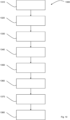
- Fig. 9 shows a flowchart of a method 1000 for jointly detecting a color and a distance of an object.
- the method 1000 includes emitting light in a predefined wavelength range. This step can be done in particular by the in Fig. 1 light element 110 shown or the first, second and third light sources 111, 112 and 113 take place.
- the method 1000 includes directing the emitted light onto an object. This can be done in particular using the in Fig. 1 transmission optics 130 shown.
- the method 1000 includes receiving light that is remitted by the object.
- the method 1000 includes directing the remitted light onto a first receiving element and a second receiving element.
- a first receiving element 210 and a second receiving element 220 can in particular be a first receiving element 210 and a second receiving element 220, as in Fig. 1 act shown. This can be done in particular using the in Fig. 1 receiving optics 230 shown.
- the method 1000 includes evaluating the light received by the first receiving element in order to determine a distance of the object.
- the method 1000 includes evaluating the light received by the second receiving element in order to determine a color of the object.
- steps 1050 and 1060 can be carried out simultaneously.
- a device for jointly detecting a color and a distance of an object in particular as in connection with Fig. 1 to 8 described, provided and/or the method 1000 is carried out with it.
- Fig. 10 shows a flowchart of a method 1300 for attaching an overlay optics, in particular an overlay optics as in connection with Fig. 1 to 8 described.
- a device for attaching an overlay optics comprising a partially flexible base element and a first, second and third positioning element arranged thereon, in particular a device for attaching an overlay optics as in Fig. 2 shown.
- step 1320 the partially flexible base element is bent and the first positioning element with the second
- Positioning element engaged and the second positioning element engaged with the third positioning element Positioning element engaged and the second positioning element engaged with the third positioning element.
- step 1330 overlay optics are provided.
- the overlay optics are arranged within a cavity created by the engagement of the first, second and third positioning elements, in particular as in Fig. 3 and 4 shown.
- a fourth positioning element is provided.
- step 1360 the fourth positioning element is brought into engagement with the first and third positioning elements and the overlay optics are thus fastened, in particular as in Fig. 5 and 6 shown.
- a fastening collar is provided.
- step 1380 the fastening sleeve is fastened to the sectionally flexible base element, as in Fig. 7 and 8th shown.
- the fastening collar can be attached to a housing, in particular to a housing of a device for jointly detecting a color and a distance of an object, as in Fig. 1 shown, attached.
Landscapes
- Physics & Mathematics (AREA)
- Engineering & Computer Science (AREA)
- General Physics & Mathematics (AREA)
- Spectroscopy & Molecular Physics (AREA)
- Remote Sensing (AREA)
- Radar, Positioning & Navigation (AREA)
- Computer Networks & Wireless Communication (AREA)
- Electromagnetism (AREA)
- General Health & Medical Sciences (AREA)
- Biochemistry (AREA)
- Immunology (AREA)
- Pathology (AREA)
- Analytical Chemistry (AREA)
- Chemical & Material Sciences (AREA)
- Life Sciences & Earth Sciences (AREA)
- Health & Medical Sciences (AREA)
- Optics & Photonics (AREA)
- Spectrometry And Color Measurement (AREA)
Abstract
Description
- Die Erfindung betrifft eine Vorrichtung und ein Verfahren zur gemeinsamen Erfassung einer Farbe und eines Abstands eines Gegenstands.
- Vorrichtungen und Verfahren, die ausgebildet sind, eine Farbe oder einen Abstand eines Gegenstand zu erkennen sind prinzipiell bekannt. Insbesondere beim Ermitteln einer Farbe ist es wünschenswert, auch den Abstand des Gegenstands zu kennen, da sich die ermittelten Farbwerte in Abhängigkeit vom Abstand des Gegenstands verändern und somit auch die Farbauflösung.
- Es ist daher eine Aufgabe, eine verbesserte Vorrichtung und ein verbessertes Verfahren zur gemeinsamen Erfassung einer Farbe und eines Abstands eines Gegenstands anzugeben.
- Diese Aufgabe wird zunächst gelöst durch eine Vorrichtung, umfassend eine Sendeeinheit, eine Empfangseinheit und eine Auswerteeinheit. Die Sendeeinheit umfasst dabei ein Lichtelement, das ausgebildet ist, Licht in einem vordefinierten Wellenlängenbereich zu emittieren und eine Sendeoptik, die ausgebildet ist, das emittierte Licht auf einen Gegenstand zu richten. Die Empfangseinheit umfasst ein erstes Empfangselement, ein zweites Empfangselement, das von dem ersten Empfangselement beabstandet angeordnet ist, und eine Empfangsoptik, die ausgebildet ist, von dem Gegenstand remittiertes Licht zu empfangen und auf das erste Empfangselement und das zweite Empfangselement zu richten. Die Auswerteeinheit ist ausgebildet, von dem ersten Empfangselement empfangenes Licht auszuwerten und einen Abstand des Gegenstands zu ermitteln und von dem zweiten Empfangselement empfangenes Licht auszuwerten und eine Farbe des Gegenstands zu ermitteln.
- Das Lichtelement ist dabei ausgebildet, Licht in einem vordefinierten Wellenlängenbereich zu emittieren, insbesondere im Bereich des sichtbaren Lichts. Dabei ist das Lichtelement insbesondere ausgebildet, chromatisch breitbandiges, sogenanntes weißes Licht zu emittieren.
- Die Sendeoptik richtet das emittierte Licht auf einen Gegenstand, dessen Farbe erkannt werden soll. Hierzu können eine oder mehrere Linsen und/oder einen oder mehrere Spiegel verwendet werden.
- Das Licht wird von dem Gegenstand remittiert und mithilfe der Empfangsoptik, die ebenfalls einen oder mehrere Linsen und/oder einen oder mehrere Spiegel aufweisen kann, auf ein erstes und ein zweites Empfangselement gerichtet. Das erste Empfangselement ist dabei ausgebildet, Abstandsinformationen zurückzuliefern und beispielsweise als Zeilensensor ausgebildet. Alternativ kann das erste Empfangselement auch als Time-of-Flight-Sensor ausgebildet sein. Das zweite Empfangselement ist ausgebildet, Farbinformationen zurückzuliefern und beispielsweise als Farbsensor ausgebildet. Insbesondere ist das zweite Empfangselement ausgebildet, in dem von dem Gegenstand remittierten Licht unterschiedliche Farbanteile zu detektieren, beispielsweise durch einen sogenannten CCD-Sensor.
- Die Auswerteeinheit wertet dann die von dem ersten und zweiten Empfangselement empfangenen Informationen aus und bestimmt so einen Abstand und eine Farbe.
- Dabei wird insbesondere ein einziges Lichtelement verwendet, um Licht zu emittieren, das sowohl für die Abstandserfassung als auch für die Farberfassung verwendet wird. Hierdurch ergibt sich ein besonders kompakter und günstiger Aufbau der Vorrichtung.
- Eine Ausführungsform der Vorrichtung sieht vor, dass das Lichtelement eine erste Lichtquelle, eine zweite Lichtquelle und eine dritte Lichtquelle aufweist, die voneinander beabstandet sind und die ausgebildet sind, Licht in drei verschiedenen vordefinierten Wellenbereichen zu emittieren, wobei die Sendeeinheit weiter eine Überlagerungsoptik aufweist, die ausgebildet ist, das von den drei Lichtquellen emittierte Licht zu überlagern und auf eine gemeinsame Strahlachse zu richten.
- Die erste, zwei und dritte Lichtquelle sind dabei insbesondere als Halbleiterlichtquellen, insbesondere Leuchtdioden ausgebildet. Dabei liegen der erste, zweite und dritte Wellenlängenbereich insbesondere im Spektrum des sichtbaren Lichts. Insbesondere liegen die drei Wellenlängenbereiche im Bereich rot, grün und blau. Die drei Wellenlängenbereiche unterscheiden sich dabei, können sich aber teilweise überlappen. Dies ist insbesondere eine alternative Ausführungsform zu der weiter oben beschriebenen Ausführungsform, in der das Lichtelement eine einzelne Lichtquelle umfasst, die ausgebildet ist, chromatisch breitbandiges, sogenanntes weißes Licht zu emittieren.
- Insbesondere können die erste, zweite und dritte Lichtquelle in dieser Ausführungsform nacheinander aktiviert werden, sodass sich ein bestimmtes Emissionsmuster aus den drei Wellenlängenbereichen ergibt. In diesem Fall kann das zweite Empfangselement derart ausgebildet sein, dass es, insbesondere nur, die Intensität des remittierten Lichts ermitteln kann und die Auswerteeinheit auf Basis dieser Intensität insbesondere unter Berücksichtigung des Emissionsmusters die Farbe des Gegenstands ermittelt.
- Durch diese Ausführungsform wird eine besonders gute Farberkennung ermöglicht.
- Eine Ausführungsform der Vorrichtung sieht vor, dass die Überlagerungsoptik einen Reflektor umfasst, der eine Vielzahl von reflektierenden Flächen aufweist, die angeordnet und ausgebildet sind, das von den drei Lichtquellen emittierte Licht zu überlagern und auf eine gemeinsame Strahlachse zu richten.
- Diese Ausführungsform der Überlagerungsoptik ist beispielsweise in der
EP 3 770 567 B1 beschrieben. - Eine alternative Ausführungsform der Vorrichtung sieht vor, dass die Überlagerungsoptik zwei dichroitische Spiegel aufweist, die angeordnet und ausgebildet sind, das von den drei Lichtquellen emittierte Licht zu überlagern und auf eine gemeinsame Strahlachse zu richten.
- Diese Ausführungsform der Überlagerungsoptik kann auch als Strahlteilertreppe bezeichnet werden.
- Eine weitere alternative Ausführungsform der Vorrichtung sieht vor, dass die Überlagerungsoptik ein erstes Prisma, ein zweites Prisma, ein drittes Prisma und ein viertes Prisma umfasst, die derart aneinander angeordnet sind, dass sie gemeinsam eine Quaderform aufweisen, wobei Kontaktflächen zwischen den Prismen dichroitisch beschichtet sind.
- Insbesondere sieht diese Ausführungsform vor, dass das erste, zweite, dritte und vierte Prisma miteinander verkittet und/oder verklebt sind, insbesondere an jeweiligen Flächen, die sich von einer der Katheten des einem Prisma zugrundeliegenden Dreiecks erstrecken.
- Durch diese drei alternativen Ausführungsformen wird eine besonders gute Überlagerung des von den drei Lichtquellen emittierten Lichts ermöglicht.
- Eine Ausführungsform der Vorrichtung sieht vor, dass sie weiter ein abschnittsweise flexibles Basiselement umfasst, an dem die erste Lichtquelle, die zweite Lichtquelle und die dritte Lichtquelle angeordnet sind, wobei das Basiselement derart um die Überlagerungsoptik herum angeordnet ist, dass je eine Lichtquelle an einer von drei benachbarten Seitenflächen der Überlagerungsoptik angeordnet ist.
- Durch diese Ausführungsform ist eine besonders einfache Montage der ersten, zweiten und dritten Lichtquelle möglich.
- Eine Ausführungsform der Vorrichtung sieht vor, dass das Basiselement ein erstes Positionierungselement, ein zweites Positionierungselement und ein drittes Positionierungselement aufweist, die die erste Lichtquelle, die zweite Lichtquelle und die dritte Lichtquelle in einem vordefinierten Abstand zu den drei benachbarten Seitenflächen der Überlagerungsoptik befestigen. Insbesondere befestigt das erste, zweite und dritte Positionierungselement die erste, zweite und dritte Lichtquelle jeweils in einer Breite, einer Länge und einer Höhe, d.h. in x, y und z im Raum, gegenüber den drei benachbarten Seitenflächen der Überlagerungsoptik.
- Optional weisen die erste Lichtquelle, die zweite Lichtquelle und die dritte Lichtquelle eine Blende auf, wobei der vordefinierte Abstand insbesondere ein direkter Kontakt, weiter insbesondere ein spaltfreier Kontakt der jeweiligen Blende mit der jeweiligen Seitenfläche der Überlagerungsoptik ist. Alternativ oder zusätzlich kann eine jeweilige Blende zwischen dem Positionierungselement und der jeweiligen Seitenfläche vorgesehen sein.
- Durch diese Ausführungsform wird eine besonders genaue Positionierung der Lichtquellen zu der Überlagerungsoptik gewährleistet.
- Eine Ausführungsform der Vorrichtung sieht vor, dass das Basiselement weiter ein viertes Positionierungselement aufweist, und wobei das erste Positionierungselement, das zweite Positionierungselement, das dritte Positionierungselement und das vierte Positionierungselement die Überlagerungsoptik an vier benachbarten Seitenflächen befestigen.
- Durch diese Ausführungsform wird eine besonders sichere Befestigung der Überlagerungsoptik ermöglicht.
- Eine Ausführungsform der Vorrichtung sieht vor, dass das vierte Positionierungselement eine Blende aufweist, die ausgebildet ist, das von der Überlagerungsoptik überlagerte Licht räumlich zu begrenzen.
- Durch diese Ausführungsform wird eine Einstellung von Größe und Form des Lichtflecks auf dem Gegenstand ermöglicht.
- Eine Ausführungsform der Vorrichtung sieht vor, dass das vierte Positionierungselement die Blende in einem vordefinierten Abstand zu der vierten Seitenfläche befestigt. Insbesondere befestigt das vierte Positionierungselement die Blende in einer Breite, einer Länge und einer Höhe, d.h. in x, y und z im Raum, gegenüber der vierten Seitenflächen der Überlagerungsoptik.
- Insbesondere ist der vordefinierte Abstand ein direkter Kontakt, weiter insbesondere ein spaltfreier Kontakt.
- Durch diese Ausführungsform wird eine besonders genaue Überlagerung ermöglicht.
- Eine Ausführungsform der Vorrichtung sieht vor, dass das erste Positionierungselement, das zweite Positionierungselement und das dritte Positionierungselement jeweils ein oberes und ein unteres Halteelement aufweisen, die ausgebildet sind die Überlagerungsoptik an einer oberen Oberfläche und einer unteren Oberfläche zu befestigen. Mithilfe dieser Halteelemente kann insbesondere die Positionierung der ersten, zweiten und dritten Lichtquelle relativ zur Überlagerungsoptik und/oder zur jeweiligen Blende sichergestellt werden.
- Durch diese Ausführungsform wird eine besonders sichere Befestigung der Überlagerungsoptik gewährleistet.
- Eine Ausführungsform der Vorrichtung sieht vor, dass die Auswerteeinheit ausgebildet ist, basierend auf dem ermittelten Abstand des Gegenstands die ermittelte Farbe zu korrigieren.
- Dazu wird der Abstand zum Gegenstand regelmäßig ermittelt, beispielsweise mit 1 kHz, wodurch eine hochfrequente Kompensation der Farbwerte ermöglicht wird. Die Korrektur der ermittelten Farbe erfolgt insbesondere anhand einer in der Auswerteeinheit hinterlegten Funktion, welche für jede Farbe und passend zu dem zweiten Empfangselement individuell während der Fertigung hinterlegt wird. Die Auswerteeinheit ermittelt beispielsweise anhand der Lichtfleckposition auf dem Zeilensensor den Abstand des Objekts mittels Triangulation und bestimmt daraus Kompensations- bzw. Korrekturfaktoren für die von dem zweiten Empfangselement ermittelte Farbe. Dieser Korrekturfaktor wird entsprechend mit dem Signalen des zweiten Empfangselement multipliziert, um den Objektabstand in der Höhe des Messignals zu kompensieren.
- Bei der Erfassung einer Farbe durch das zweite Empfangselement in unterschiedlichen Abständen kann sich das erfasste Messignal um mehrere Größenordnungen ändern. Da die Auflösbarkeit von Farbunterschieden in erster Linie abhängig vom Unterschied des erfassten Messignals ist, ändert sich mit unterschiedlichen Objektabständen auch die Auflösbarkeit von Farbunterschieden. Um die Farbauflösung möglichst über den gesamten Arbeitsbereich optimal zu halten, wird die elektrische Verstärkung des Messsignal des zweiten Empfangselements abhängig von der Höhe des Messignals und damit auch dem Abstand des Objekts dynamisch eingestellt. Entsprechend wird die elektrische Verstärkung bei großen Abständen und geringen Signalhöhe vergrößert, bei kleinen Abständen und intensiven Signalen verkleinert.
- Die in der Auswerteeinheit eingestellte und für die Applikation nutzbare Farbauflösung wird entsprechend der eingestellten elektrischen Verstärkung und des ermittelten Abstandskorrekturfaktors angepasst. Sie lässt sich damit in Abhängigkeit der Applikationsbedingungen justieren
- Durch diese Ausführungsform wird eine besonders genaue Farbermittlung ermöglicht.
- Eine Ausführungsform der Vorrichtung sieht vor, dass die Empfangsoptik einstückig ausgebildet ist. Einstückig meint vorliegend aus einem zusammenhängenden Material und kann auch als integral bezeichnet werden.
- Durch diese Ausführungsform wird ein besonders kompakter Aufbau der Vorrichtung ermöglicht.
- Die eingangs genannte Aufgabe wird auch gelöst durch ein Verfahren zur gemeinsamen Erfassung einer Farbe und eines Abstands eines Gegenstands.
- Dabei umfasst das Verfahren ein Emittieren von Licht in einem vordefinierten Wellenlängenbereich, ein Richten des emittierten Lichts auf einen Gegenstand, ein Empfangen von von dem Gegenstand remittiertem Licht, ein Richten des remittierten Lichts auf ein erstes Empfangselement und ein zweites Empfangselement, ein Auswerten des von dem ersten Empfangselement empfangenen Lichts um einen Abstand des Gegenstands zu ermitteln und ein Auswerten des von dem zweiten Empfangselement empfangenen Lichts um eine Farbe des Gegenstands zu ermitteln.
- Bezüglich der Ausgestaltungen und Vorteile des Verfahrens zur gemeinsamen Erfassung einer Farbe und eines Abstands eines Gegenstands wird auf die Ausgestaltungen und Vorteile der Vorrichtung zur gemeinsamen Erfassung einer Farbe und eines Abstands eines Gegenstands verwiesen.
- Ebenfalls ist erfindungsgemäß eine Vorrichtung zur Befestigung einer Überlagerungsoptik vorgesehen. Die Vorrichtung umfasst ein abschnittsweise flexibles Basiselement, und ein erstes, zweites und drittes Positionierungselement, die an dem flexiblen Basiselement angeordnet sind, wobei das abschnittsweise flexible Basiselement derart verbiegbar ist, dass das erste Positionierungselement mit dem zweiten Positionierungselement und das zweite Positionierungselement mit dem dritten Positionierungselement in Eingriff gebracht werden kann und so einen Hohlraum bildet, in dem eine Überlagerungsoptik angeordnet werden kann. Die Vorrichtung umfasst auch ein viertes Positionierungselement, das mit dem ersten und dem dritten Positionierungselement in Eingriff gebracht werden kann und so die Überlagerungsoptik an der Vorrichtung befestigt.
- Bezüglich der Ausgestaltungen und Vorteile der Vorrichtung zur Befestigung einer Überlagerungsoptik wird auf die Ausgestaltungen und Vorteile der Vorrichtung zur gemeinsamen Erfassung einer Farbe und eines Abstands eines Gegenstands verwiesen.
- Auch ist erfindungsgemäß ein Verfahren zur Befestigung einer Überlagerungsoptik vorgesehen. Das Verfahren umfasst dabei die Schritte Bereitstellen einer Vorrichtung zur Befestigung einer Überlagerungsoptik, umfassend ein abschnittsweise flexibles Basiselement und ein erstes, zweites und drittes daran angeordnetes Positionierungselement; Verbiegen des abschnittsweise flexiblen Basiselements; in Eingriff Bringen des ersten Positionierungselements mit dem zweiten Positionierungselement; in Eingriff Bringen des zweiten Positionierungselements mit dem dritten Positionierungselement; Anordnen einer Überlagerungsoptik innerhalb eines Hohlraums, der durch den Eingriff des ersten, zweiten und dritten Positionierungselements entstanden ist; in Eingriff bringen eines vierten Positionierungselements mit dem ersten und dem dritten Positionierungselement und somit Befestigen der Überlagerungsoptik.
- Bezüglich der Ausgestaltungen und Vorteile des Verfahrens zur Befestigung einer Überlagerungsoptik wird auf die Ausgestaltungen und Vorteile der Vorrichtung zur Befestigung einer Überlagerungsoptik vorgesehen.
- Ausführungsformen der Vorrichtung und des Verfahrens zur gemeinsamen Erfassung einer Farbe und eines Abstands eines Gegenstands sowie der Vorrichtung und des Verfahrens zur Befestigung einer Überlagerungsoptik werden nun im Zusammenhang mit den folgenden Figuren näher beschrieben. Es zeigen:
- Fig. 1
- eine schematische Draufsicht einer Vorrichtung zur gemeinsamen Erfassung einer Farbe und eines Abstands eines Gegenstands;
- Fig. 2
- eine perspektivische Ansicht einer Vorrichtung zur Befestigung einer Überlagerungsoptik;
- Fig. 3
- eine perspektivische Ansicht einer Vorrichtung aus
Fig. 2 ; - Fig. 4
- eine Draufsicht der in
Fig. 3 gezeigten Vorrichtung im Querschnitt; - Fig. 5
- eine weitere perspektivische Ansicht einer Vorrichtung aus
Fig. 2 ; - Fig. 6
- eine Draufsicht der in
Fig. 5 gezeigten Vorrichtung im Querschnitt; - Fig. 7
- eine weitere perspektivische Ansicht einer Vorrichtung aus
Fig. 2 ; - Fig. 8
- eine Draufsicht der in
Fig. 7 gezeigten Vorrichtung im Querschnitt; - Fig. 9
- ein Ablaufdiagramm eines Verfahrens zur gemeinsamen Erfassung einer Farbe und eines Abstands eines Gegenstands; und
- Fig. 10
- ein Ablaufdiagramm eines Verfahrens zur Befestigung einer Überlagerungsoptik.
- Dabei bezeichnen gleiche Bezugszeichen gleiche oder ähnliche Merkmale.
-
Fig. 1 zeigt eine schematische Draufsicht einer Vorrichtung 10 zur gemeinsamen Erfassung einer Farbe und eines Abstands eines Gegenstands. - Die Vorrichtung 10 weist eine Sendeeinheit 100, eine Empfangseinheit 200 und eine Auswerteeinheit auf, die aus Gründen der Übersichtlichkeit nicht gezeigt ist.
- Die Sendeeinheit 100 umfasst ein Lichtelement 110. Das Lichtelement 110 umfasst dabei eine erste Lichtquelle 111, eine zweite Lichtquelle 112 und eine dritte Lichtquelle 113, die jeweils voneinander beabstandet sind. Die erste Lichtquelle 111 ist dabei ausgebildet Licht in einem ersten vordefinierten Wellenbereich zu emittieren, die zweite Lichtquelle 112 ist ausgebildet Licht in einem zweiten vordefinierten Wellenbereich zu emittieren und die dritte Lichtquelle 112 ist ausgebildet Licht in einem dritten vordefinierten Wellenbereich zu emittieren. Der erste Wellenbereich, der zweite Wellenbereich und der dritte Wellenbereich unterscheiden sich dabei, können sich jedoch teilweise überlappen.
- Die Sendeeinheit 100 umfasst auch eine Überlagerungsoptik, die ausgebildet ist, das von den drei Lichtquellen 111, 112, 113 emittierte Licht zu überlagern und auf eine gemeinsame Strahlachse zu richten. Dabei ist die Überlagerungsoptik hier beispielhaft als Strahlüberlagerungswürfel 115 abgebildet. Der Strahlüberlagerungswürfel besteht aus vier aneinander befestigten Prismen, welche auf den Kontaktflächen miteinander dichroitisch beschichtet sind. Der Strahlüberlagerungswürfel weist dabei vier gleich große, rechteckig zueinander angeordnete rechteckige Seitenflächen auf sowie eine rechteckige Dach- und eine Bodenfläche, die ebenfalls rechtwinklig zu den Seitenflächen angeordnet sind und entweder eine gleiche Größe aufweisen wie die Seitenflächen oder eine davon verschiedene Größe. Der Begriff Würfel fasst vorliegend somit auch Quader mit ein.
- Die drei Lichtquellen 111, 112, 113 sind dabei derart um die Seiten des Strahlüberlagerungswürfels 115 angeordnet, dass eine Strahlrichtung des durch die erste Lichtquelle 111 emittierten Lichts um 90 Grad in der Zeichnungsebene zu einer Strahlrichtung des durch die zweite Lichtquelle 112 emittierten Lichts versetzt ist und eine Strahlrichtung des durch die zweite Lichtquelle 112 emittierten Lichts um 90 Grad in der Zeichnungsebene zu einer Strahlrichtung des durch die dritte Lichtquelle 113 emittierten Lichts versetzt ist, die erste Lichtquelle 111 und die dritte Lichtquelle 113 sich also um 180 Grad in der Zeichnungsebene gegenüberstehen. Der Strahlüberlagerungswürfel 115 ist dabei derart angeordnet und ausgebildet, die drei Strahlrichtungen der drei Lichtquellen derart zu richten und zu überlagern, dass ein gemeinsamer Lichtstrahl in gegenüber der zweiten Lichtquelle 112, aus dem Strahlüberlagerungswürfel 115 emittiert wird.
- Insbesondere kann die Vorrichtung 10 auch eine Vorrichtung zur Befestigung einer Überlagerungsoptik umfassen, die in der folgenden
Fig. 2 noch näher beschrieben wird. - Andere Ausführungsformen einer Überlagerungsoptik, wie beispielsweise einen Reflektor, der eine Vielzahl von reflektierenden Flächen aufweist oder zwei dichroitische Spiegel, die ebenfalls ausgebildet sind, das von den drei Lichtquellen emittierte Licht zu überlagern und auf eine gemeinsame Strahlachse zu richten, die jedoch nicht in den Figuren gezeigt sind, sind ebenso möglich.
- Die Sendeeinheit 100 umfasst auch eine Umlenkoptik 120, die ausgebildet ist, das von den drei Lichtquellen 111, 112, 113 emittierte und durch die Überlagerungsoptik überlagerte Licht umzulenken und auf eine Sendeoptik 130 umzulenken. Die Sendeoptik ist dabei ausgebildet, das von den drei Lichtquellen 111, 112, 113 emittierte Licht auf einen Gegenstand zu richten. Der Gegenstand ist aus Gründen den Übersichtlichkeit nicht gezeigt und befindet sich dabei rechts von der Vorrichtung 10, außerhalb der Zeichenfläche.
- Die Vorrichtung 10 umfasst auch eine Frontscheibe 250, durch die das von den drei Lichtquellen 111, 112, 113 emittierte Licht aus der Vorrichtung austritt, was durch den Strahlengang 1 gezeigt ist. Das emittierte Licht wird dann an dem Gegenstand remittiert, was durch den Strahlengang 2 gezeigt und tritt als remittiertes Licht durch die Frontscheibe 250 wieder in die Vorrichtung 10 ein.
- Dort trifft das remittierte Licht auf eine Empfangsoptik 230 der Empfangseinheit 200, die das remittierte Licht auf ein erstes Empfangselement 210 einerseits und auf ein zweites Empfangselement 220 andererseits, das von dem ersten Empfangselement 210 beabstandet ist, richtet. Das erste Empfangselement 210 und das zweite Empfangselement 220 sind dabei ausgebildet, das auf sie gerichtete Licht zu empfangen und in ein elektrisches Signal umzuwandeln.
- Die nicht abgebildete Auswerteeinheit ist dabei ausgebildet ist, das von dem ersten Empfangselement 210 empfangene Licht bzw. das davon gebildete elektrische Signal auszuwerten und einen Abstand des Gegenstands zu ermitteln. Die Auswerteeinheit ist auch ausgebildet, das von dem zweiten Empfangselement 220 empfangene Licht bzw. das davon gebildete elektrische Signal auszuwerten und eine Farbe des Gegenstands zu ermitteln.
- Sowohl die Sendeeinheit 100 mit all ihren beschriebenen Komponenten als auch die Empfangseinheit 200 mit all ihren beschriebenen Komponenten sind dabei in einem einzelnen, aus Gründen der Übersichtlichkeit nicht gezeigten Gehäuse untergebracht, das als einzige optische Schnittstelle die Frontscheibe 250 aufweist. Die Auswerteeinheit kann entweder in dem Gehäuse oder außerhalb davon angeordnet sein. Insbesondere nutzt die Vorrichtung 10 zur gemeinsamen Erfassung einer Farbe und eines Abstands eines Gegenstands ein einzelnes Lichtelement 110 umfassend drei, insbesondere genau drei Lichtquellen, die sowohl zur Bestimmung einer Farbe als auch zur Bestimmung eines Abstands des Gegenstands verwendet werden.
-
Fig. 2 zeigt eine perspektivische Ansicht einer Vorrichtung 300, die zur Befestigung einer Überlagerungsoptik dient, insbesondere einer Überlagerungsoptik wie inFig. 1 abgebildet. Dabei befindet sich die Vorrichtung 300 wie inFig. 2 gezeigt in einem Teilschritt eines Verfahrens zur Befestigung einer Überlagerungsoptik, welches noch im Detail im Zusammenhang mitFig. 10 beschrieben wird. - Wie in
Fig. 2 zunächst gezeigt umfasst die Vorrichtung 300 zur Befestigung einer Überlagerungsoptik ein abschnittsweise flexibles Basiselement 310, umfassend einen ersten starren Abschnitt 311, einen zweiten starren Abschnitt 312, einen dritten starren Abschnitt 313 und einen vierten starren Abschnitt 314. - Am ersten starren Abschnitt 311 ist ein erstes Positionierungselement 320 angeordnet, am zweiten starren Abschnitt 312 ist ein zweites Positionierungselement 330 angeordnet und am dritten starren Abschnitt 313 ist ein drittes Positionierungselement 340 angeordnet.
- Das erste Positionierungselement 320, das zweite Positionierungselement 330 und das dritte Positionierungselement 340 sind dabei im wesentlichen gleichförmig ausgebildet, wobei jedes der Positionierungselemente mehrere Halteelemente und mehrere Arretierungselemente aufweist, die im Folgenden beschrieben werden.
- Das erste Positionierungselement 320 weist ein oberes Halteelement 321, ein unteres Halteelement 324 sowie vier seitliche Arretierungselemente 322, 323, 325 und 326 auf. Ebenso weist das zweite Positionierungselement 330 weist ein oberes Halteelement 331, ein unteres Halteelement 334 sowie vier seitliche Arretierungselemente 332, 333, 335 und 336 auf. Auch weist das weist dritte Positionierungselement 340 ein oberes Halteelement 341, ein unteres Halteelement 344 sowie vier seitliche Arretierungselemente 342, 343, 345 und 346 auf. Dabei sind jeweils die zwei linken seitlichen Arretierungselemente 322 und 323, 332 und 333 sowie 342 und 343 nach außen versetzt zu den jeweils korrespondierenden zwei rechten seitlichen Arretierungselementen 325 und 326, 335 und 336 sowie 345 und 346 angeordnet.
- Dabei sind die die Arretierungselemente derart angeordnet, dass sie mit dazu korrespondierenden Nuten in dem jeweils benachbarten Positionierungselement eingreifen können und so die Positionierungselemente aneinander befestigen können.
- Zentral in jedem der drei Positionierungselemente 320, 330, 340 ist eine Lichtquelle angeordnet, wobei nur die erste Lichtquelle 111 in dem ersten Positionierungselement 320 mit einem Bezugszeichen versehen ist. Jede der drei Lichtquellen ist dabei mit einer Blende versehen, die aus Gründen der Übersichtlichkeit ebenfalls nicht gezeigt ist.
- Dabei sind das erste Positionierungselement 320, das zweite Positionierungselement 330 und das dritte Positionierungselement 340 im SMD-Prozess auf dem abschnittsweise flexiblen Basiselement 310 befestigt.
- Zwischen dem ersten starren Abschnitt 311 und dem zweiten starren Abschnitt 312 ist ein erster flexibler Abschnitt angeordnet und zwischen dem zweiten starren Abschnitt 312 und dem dritten starren Abschnitt 313 ist ein zweiter flexibler Abschnitt angeordnet, wobei die starren Abschnitte 315 und 316 aus Gründen der Übersichtlichkeit nicht mit einem Bezugszeichen versehen sind. Das Basiselement 310 kann auch weitere flexible Abschnitte aufweisen, die hier nicht im Detail mit Bezugszeichen versehen sind.
- Der vierte starre Abschnitt 314 weist darüber hinaus Befestigungs- und/oder Anschlusselemente zum Befestigen und/oder Anschließen der Vorrichtung 300 an einem Gehäuse einer Vorrichtung 10 zur gemeinsamen Erfassung einer Farbe und eines Abstands eines Gegenstands, wie in
Fig. 1 gezeigt, auf, die hier aus Gründen der Übersichtlichkeit nicht mit Bezugszeichen versehen sind. -
Fig. 3 zeigt eine perspektivische Ansicht einer Vorrichtung 300 zur Befestigung einer Überlagerungsoptik wie inFig. 2 gezeigt. Dabei befindet sich die Vorrichtung 300 wie inFig. 3 gezeigt in einem weiteren Teilschritt eines Verfahrens zur Befestigung einer Überlagerungsoptik, welches noch im Detail im Zusammenhang mitFig. 10 beschrieben wird. - Wie in
Fig. 3 ersichtlich wurde eine Überlagerungsoptik in Form eines Strahlüberlagerungswürfels 115, wie bereits inFig. 1 beschrieben, bereitgestellt. Wie ebenfalls inFig. 3 ersichtlich weist der Strahlüberlagerungswürfel 115 eine im Wesentlichen quaderförmige Form auf und ist aus vier Prismen zusammengesetzt. - Um den Strahlüberlagerungswürfel 115 herum wurden in diesem in dieser
Fig. 3 gezeigten Verfahrensschritt die drei starren Abschnitte 311, 312, 313 mit den daran angeordneten Positionierungselementen 320, 330, 340 mithilfe der flexiblen Abschnitte 315 und 316 derart um den Strahlüberlagerungswürfel 115 angeordnet, dass sie diesen an drei der vier Seitenflächen kontaktieren. Insbesondere krümmen sich die flexiblen Abschnitte 315 und 316 derart, dass sie einen Viertelkreis ausbilden. - Wie in dieser
Fig. 3 ebenfalls ersichtlich liegen die oberen Halteelemente 321, 331 und 341 an dem Strahlüberlagerungswürfel 115 an. Ebenso liegen die unteren Halteelemente, die in dieserFig. 3 aus perspektivischen Gründen nicht sichtbar sind, an dem Strahlüberlagerungswürfel 115 an und fixieren diesen somit an fünf von sechs Flächen. -
Fig. 4 zeigt eine Draufsicht der inFig. 3 gezeigten Vorrichtung 300 im Querschnitt. Hier ist insbesondere noch einmal die viertelkreisförmige Form der flexiblen Abschnitte 315 und 316 ersichtlich. - Ebenso ist in
Fig. 4 ersichtlich, dass der Strahlüberlagerungswürfel 115 an drei der vier Seitenflächen von den jeweiligen Positionierungselementen kontaktiert und somit in Position gehalten wird. - Auch sind in
Fig. 4 die erste Lichtquelle 111, die zweite Lichtquelle 112 und die dritte Lichtquelle 113 ersichtlich, die die drei der vier Seitenflächen mithilfe einer Blende beleuchten können. -
Fig. 5 zeigt eine perspektivische Ansicht einer Vorrichtung 300 zur Befestigung einer Überlagerungsoptik wie inFig. 2 undFig. 4 gezeigt. Dabei befindet sich die Vorrichtung 300 wie inFig. 5 gezeigt in einem weiteren Teilschritt eines Verfahrens zur Befestigung einer Überlagerungsoptik, welches noch im Detail im Zusammenhang mitFig. 10 beschrieben wird. - Wie in
Fig. 5 ersichtlich wurde ein viertes Positionierungselement 350 bereitgestellt, das im Wesentlichen den anderen drei Positionierungselementen gleicht. Abweichend von den anderen drei Positionierungselementen ist jedoch im vierten Positionierungselement 350 keine Lichtquelle vorgesehen, sondern lediglich eine Blende, die eine Form und Größe, beispielsweise einen Durchmesser, des durch den Strahlüberlagerungswürfel 115 emittierten, gemeinsamen Lichtstrahls definiert. - Ebenso ist in
Fig. 5 ersichtlich, dass ein oberes Halteelement 351 des vierten Positionierungselements 350 den Strahlüberlagerungswürfel 115 an der Oberseite kontaktiert und so befestigt. Ebenso kontaktiert ein unteres, nicht gezeigtes Halteelement den Strahlüberlagerungswürfel 115 an der Unterseite. Auch greifen weitere vier Arretierungselemente des vierten Positionierungselements 350, die aus perspektivischen Gründen nicht gezeigt sind, mit ebenfalls nicht gezeigten korrespondierenden Nuten in dem benachbarten ersten Positionierungselement 320 und dem ebenfalls benachbarten dritten Positionierungselement 340 ein und befestigen so den Strahlüberlagerungswürfel 115 von allen sechs Seiten. -
Fig. 6 zeigt eine Draufsicht der inFig. 5 gezeigten Vorrichtung 300. - In dieser
Fig. 6 ist noch einmal ersichtlich, dass das vierte Positionierungselement 350 keine Lichtquelle, sondern lediglich eine Blende aufweist. -
Fig. 7 zeigt eine perspektivische Ansicht einer Vorrichtung 300 zur Befestigung einer Überlagerungsoptik wie inFig. 2 ,Fig. 4 undFig. 6 gezeigt. Dabei befindet sich die Vorrichtung 300 wie inFig. 7 gezeigt in einem weiteren Teilschritt eines Verfahrens zur Befestigung einer Überlagerungsoptik, welches noch im Detail im Zusammenhang mitFig. 10 beschrieben wird. - Dabei ist die Vorrichtung 300 in eine Befestigungsmanschette 400 eingeführt. Die Befestigungsmanschette 400 umfasst eine obere Oberfläche 410, eine untere Oberfläche 450 sowie drei Seitenflächen 420, 430 und 440. Eine vierte Seitenfläche ist nicht vorgesehen. So kann die Vorrichtung besonders einfach in die Befestigungsmanschette 400 eingeführt werden.
- Die linke und rechte Seitenfläche 420 und 440 umfassen dabei ein Befestigungselement, von denen nur das der linken Seitenfläche mit einem Bezugszeichen 422 versehen ist. Die obere Oberfläche 410 und die untere Oberfläche 450 umfassen jeweils auch Befestigungselemente 411 und 451. Diese Befestigungselemente dienen dazu, die Vorrichtung 300 in einem Gehäuse zu befestigen.
-
Fig. 8 zeigt eine Draufsicht der inFig. 7 gezeigten Vorrichtung 300. - Dabei ist insbesondere auch das Befestigungselement 442 der rechten Seitenfläche ersichtlich.
-
Fig. 9 zeigt ein Ablaufdiagramm eines Verfahrens 1000 zur gemeinsamen Erfassung einer Farbe und eines Abstands eines Gegenstands. - Das Verfahren 1000 umfasst dabei in einem ersten Schritt 1010 ein Emittieren von Licht in einem vordefinierten Wellenlängenbereich. Dieser Schritt kann insbesondere durch das in
Fig. 1 gezeigte Lichtelement 110 bzw. die erste, zweite und dritte Lichtquelle 111, 112 und 113 erfolgen. - In einem weiteren Schritt 1020 umfasst das Verfahren 1000 ein Richten des emittierten Lichts auf einen Gegenstand. Dies kann insbesondere mithilfe der in
Fig. 1 gezeigten Sendeoptik 130 erfolgen. - In einem weiteren Schritt 1030 umfasst das Verfahren 1000 ein Empfangen von Licht, das von dem Gegenstand remittiert wird.
- In einem weiteren Schritt 1040 umfasst das Verfahren 1000 ein Richten des remittierten Lichts auf ein erstes Empfangselement und ein zweites Empfangselement. Dabei kann es sich insbesondere um ein erstes Empfangselement 210 und ein zweites Empfangselement 220, wie in
Fig. 1 gezeigt handeln. Dies kann insbesondere mithilfe der inFig. 1 gezeigten Empfangsoptik 230 erfolgen. - In einem weiteren Schritt 1050 umfasst das Verfahren 1000 ein Auswerten des von dem ersten Empfangselement empfangenen Lichts um einen Abstand des Gegenstands zu ermitteln.
- In einem weiteren Schritt 1060 umfasst das Verfahren 1000 ein Auswerten des von dem zweiten Empfangselement empfangenen Lichts um eine Farbe des Gegenstands zu ermitteln.
- Die beschriebenen Verfahrensschritte, insbesondere die Schritte 1050 und 1060, können dabei gleichzeitig ausgeführt werden.
- In einem weiteren Schritt, der nicht in
Fig. 9 gezeigt ist, und der insbesondere vor dem ersten Schritt 1010 erfolgen kann, wird eine Vorrichtung zur gemeinsamen Erfassung einer Farbe und eines Abstands eines Gegenstands, insbesondere wie im Zusammenhang mit denFig. 1 bis 8 beschrieben, bereitgestellt und/oder mit ihr das Verfahren 1000 durchgeführt. -
Fig. 10 zeigt ein Ablaufdiagramm eines Verfahrens 1300 zur Befestigung einer Überlagerungsoptik, insbesondere einer Überlagerungsoptik wie im Zusammenhang mit denFig. 1 bis 8 beschrieben. - In einem ersten Schritt 1310 wird eine Vorrichtung zur Befestigung einer Überlagerungsoptik bereitgestellt, umfassend ein abschnittsweise flexibles Basiselement und ein erstes, zweites und drittes daran angeordnetes Positionierungselement, insbesondere eine Vorrichtung zur Befestigung einer Überlagerungsoptik wie in
Fig. 2 gezeigt. - In einem folgenden Schritt 1320 wird das abschnittsweise flexible Basiselement verbogen und das erste Positionierungselement mit dem zweiten
- Positionierungselement in Eingriff gebracht sowie das zweite Positionierungselement mit dem dritten Positionierungselement in Eingriff gebracht.
- In einem weiteren Schritt 1330 wird eine Überlagerungsoptik bereitgestellt.
- In einem weiteren Schritt 1340 wird die Überlagerungsoptik innerhalb eines Hohlraums, der durch den Eingriff des ersten, zweiten und dritten Positionierungselement entstanden ist, angeordnet, insbesondere wie in
Fig. 3 und4 gezeigt. - In einem weiteren Schritt 1350 wird ein viertes Positionierungselement bereitgestellt.
- In einem darauffolgenden Schritt 1360 wird das vierte Positionierungselement mit dem ersten und dem dritten Positionierungselement in Eingriff gebracht und so die Überlagerungsoptik befestigt, insbesondere wie in
Fig. 5 und6 gezeigt. - In einem weiteren Schritt 1370 wird eine Befestigungsmanschette bereitgestellt.
- In einem darauffolgenden Schritt 1380 wird die Befestigungsmanschette an dem abschnittsweise flexiblen Basiselement befestigt, wie in
Fig. 7 und8 gezeigt. - In einem optionalen, nicht gezeigten Schritt kann die Befestigungsmanschette an einem Gehäuse, insbesondere an einem Gehäuse einer Vorrichtung zur gemeinsamen Erfassung einer Farbe und eines Abstands eines Gegenstands, wie in
Fig. 1 gezeigt, befestigt werden. -
- 10
- Vorrichtung
- 100
- Sendeeinheit
- 110
- Lichtelement
- 111
- erste Lichtquelle
- 112
- zweite Lichtquelle
- 113
- dritte Lichtquelle
- 115
- Strahlüberlagerungswürfel
- 120
- Umlenkoptik
- 130
- Sendeoptik
- 200
- Empfangseinheit
- 210
- erstes Empfangselement
- 220
- zweites Empfangselement
- 230
- Empfangsoptik
- 250
- Frontscheibe
- 300
- Vorrichtung
- 310
- Basiselement
- 311
- erster starrer Abschnitt
- 312
- zweiter starrer Abschnitt
- 313
- dritter starrer Abschnitt
- 314
- vierter starrer Abschnitt
- 315
- erster flexibler Abschnitt
- 316
- zweiter flexibler Abschnitt
- 320
- erstes Positionierungselement
- 321
- oberes Halteelement
- 322
- Arretierungselement
- 323
- Arretierungselement
- 324
- unteres Halteelement
- 325
- Arretierungselement
- 326
- Arretierungselement
- 330
- zweites Positionierungselement
- 331
- oberes Halteelement
- 332
- Arretierungselement
- 333
- Arretierungselement
- 334
- unteres Halteelement
- 335
- Arretierungselement
- 336
- Arretierungselement
- 340
- drittes Positionierungselement
- 341
- oberes Halteelement
- 342
- Arretierungselement
- 343
- Arretierungselement
- 344
- unteres Halteelement
- 345
- Arretierungselement
- 346
- Arretierungselement
- 350
- viertes Positionierungselement
- 351
- oberes Halteelement
- 400
- Befestigungsmanschette
- 410
- obere Oberfläche
- 411
- Befestigungselement
- 420
- Seitenfläche
- 422
- Befestigungselement
- 430
- Seitenfläche
- 440
- Seitenfläche
- 442
- Befestigungselement
- 450
- untere Oberfläche
- 451
- Befestigungselement
- 1000
- Verfahren
- 1010
- Verfahrensschritt
- 1020
- Verfahrensschritt
- 1030
- Verfahrensschritt
- 1040
- Verfahrensschritt
- 1050
- Verfahrensschritt
- 1060
- Verfahrensschritt
- 1300
- Verfahrensschritt
- 1310
- Verfahrensschritt
- 1320
- Verfahrensschritt
- 1330
- Verfahrensschritt
- 1340
- Verfahrensschritt
- 1350
- Verfahrensschritt
- 1360
- Verfahrensschritt
- 1370
- Verfahrensschritt
- 1380
- Verfahrensschritt
Claims (14)
- Vorrichtung (10) zur gemeinsamen Erfassung einer Farbe und eines Abstands eines Gegenstands, umfassend:- eine Sendeeinheit (100), umfassend:- ein Lichtelement (110), das ausgebildet ist, Licht in einem vordefinierten Wellenlängenbereich zu emittieren; und- eine Sendeoptik (130), die ausgebildet ist, das emittierte Licht auf einen Gegenstand zu richten;- eine Empfangseinheit (200), umfassend- ein erstes Empfangselement (210);- ein zweites Empfangselement (220), das von dem ersten Empfangselement (210) beabstandet angeordnet ist, und- eine Empfangsoptik (230);- wobei die Empfangsoptik ausgebildet ist, von dem Gegenstand remittiertes Licht zu empfangen und auf das erste Empfangselement (220) und das zweite Empfangselement (230) zu richten; und- eine Auswerteeinheit, die ausgebildet ist, von dem ersten Empfangselement (210) empfangenes Licht auszuwerten und einen Abstand des Gegenstands zu ermitteln und von dem zweiten Empfangselement (220) empfangenes Licht auszuwerten und eine Farbe des Gegenstands zu ermitteln.
- Vorrichtung nach Anspruch 1,wobei das Lichtelement (110) eine erste Lichtquelle (111), eine zweite Lichtquelle (112) und eine dritte Lichtquelle (113) aufweist, die voneinander beabstandet sind und die ausgebildet sind, Licht in drei verschiedenen vordefinierten Wellenbereichen zu emittieren,wobei die Sendeeinheit (100) weiter eine Überlagerungsoptik aufweist, die ausgebildet ist, das von den drei Lichtquellen (111, 112, 113) emittierte Licht zu überlagern und auf eine gemeinsame Strahlachse zu richten.
- Vorrichtung nach Anspruch 2,
wobei die Überlagerungsoptik einen Reflektor umfasst, der eine Vielzahl von reflektierenden Flächen aufweist, die angeordnet und ausgebildet sind, das von den drei Lichtquellen emittierte Licht zu überlagern und auf eine gemeinsame Strahlachse zu richten. - Vorrichtung nach Anspruch 2,
wobei die Überlagerungsoptik einen Spiegel und zwei dichroitische Spiegel, die angeordnet und ausgebildet sind, das von den drei Lichtquellen emittierte Licht zu überlagern und auf eine gemeinsame Strahlachse zu richten. - Vorrichtung nach Anspruch 2,
wobei die Überlagerungsoptik ein erstes Prisma, ein zweites Prisma, ein drittes Prisma und ein viertes Prisma umfasst, die derart aneinander angeordnet sind, dass sie gemeinsam eine Quaderform aufweisen, wobei Kontaktflächen zwischen den Prismen dichroitisch beschichtet und angeordnet und ausgebildet sind, das von den drei Lichtquellen emittierte Licht zu überlagern und auf eine gemeinsame Strahlachse zu richten. - Vorrichtung nach Anspruch 5,
weiter umfassend ein abschnittsweise flexibles Basiselement (310), an dem die erste Lichtquelle (111), die zweite Lichtquelle (112) und die dritte Lichtquelle (113) angeordnet sind, wobei das Basiselement (310) derart um die Überlagerungsoptik herum angeordnet ist, dass je eine Lichtquelle an einer von drei benachbarten Seitenflächen der Überlagerungsoptik angeordnet ist. - Vorrichtung nach Anspruch 6,
wobei das Basiselement (310) ein erstes Positionierungselement (320), ein zweites Positionierungselement (330) und ein drittes Positionierungselement (340) aufweist, die die erste Lichtquelle (111), die zweite Lichtquelle (112) und die dritte Lichtquelle (113) in einem vordefinierten Abstand zu den drei benachbarten Seitenflächen der Überlagerungsoptik befestigen. - Vorrichtung nach Anspruch 7,
wobei das Basiselement (310) weiter ein viertes Positionierungselement (350) aufweist, und wobei das erste Positionierungselement (320), das zweite Positionierungselement (330), das dritte Positionierungselement (340) und das vierte Positionierungselement (350) die Überlagerungsoptik an vier benachbarten Seitenflächen befestigen. - Vorrichtung nach Anspruch 8,
wobei das vierte Positionierungselement (350) eine Blende aufweist, die ausgebildet ist, das von der Überlagerungsoptik überlagerte Licht räumlich zu begrenzen. - Vorrichtung nach Anspruch 9,
wobei das vierte Positionierungselement (350) die Blende in einem vordefinierten Abstand zu der vierten Seitenfläche befestigt. - Vorrichtung nach einem der Ansprüche 7 bis 10, wobei das erste Positionierungselement (320), das zweite Positionierungselement (330) und das dritte Positionierungselement jeweils ein oberes und ein unteres Halteelement (321, 324; 331, 334; 341, 344) aufweisen, die ausgebildet sind die Überlagerungsoptik an einer oberen Oberfläche und einer unteren Oberfläche zu befestigen.
- Vorrichtung nach einem der vorstehenden Ansprüche,
wobei die Auswerteeinheit (300) ausgebildet ist, basierend auf dem ermittelten Abstand des Gegenstands die ermittelte Farbe zu korrigieren. - Vorrichtung nach einem der vorstehenden Ansprüche,
wobei die Empfangsoptik (230) einstückig ausgebildet ist. - Verfahren (1000) zur gemeinsamen Erfassung einer Farbe und eines Abstands eines Gegenstands, umfassend:- Emittieren (1010) von Licht in einem vordefinierten Wellenlängenbereich- Richten (1020) des emittierten Lichts auf einen Gegenstand;- Empfangen (1030) von von dem Gegenstand remittiertem Licht- Richten (1040) des remittierten Lichts auf ein erstes Empfangselement und ein zweites Empfangselement;- Auswerten (1050) des von dem ersten Empfangselement empfangenen Lichts um einen Abstand des Gegenstands zu ermitteln; und- Auswerten (1060) des von dem zweiten Empfangselement empfangenen Lichts um eine Farbe des Gegenstands zu ermitteln.
Priority Applications (3)
| Application Number | Priority Date | Filing Date | Title |
|---|---|---|---|
| EP22175219.9A EP4283329B1 (de) | 2022-05-24 | 2022-05-24 | Vorrichtung und verfahren zur gemeinsamen erfassung einer farbe und eines abstands eines gegenstands |
| CN202310585860.5A CN117109742A (zh) | 2022-05-24 | 2023-05-23 | 用于联合检测物体的颜色和距离的装置和方法 |
| US18/200,732 US20230384214A1 (en) | 2022-05-24 | 2023-05-23 | Apparatus and method for jointly detecting a color and a distance of an object |
Applications Claiming Priority (1)
| Application Number | Priority Date | Filing Date | Title |
|---|---|---|---|
| EP22175219.9A EP4283329B1 (de) | 2022-05-24 | 2022-05-24 | Vorrichtung und verfahren zur gemeinsamen erfassung einer farbe und eines abstands eines gegenstands |
Publications (2)
| Publication Number | Publication Date |
|---|---|
| EP4283329A1 true EP4283329A1 (de) | 2023-11-29 |
| EP4283329B1 EP4283329B1 (de) | 2024-07-03 |
Family
ID=82058445
Family Applications (1)
| Application Number | Title | Priority Date | Filing Date |
|---|---|---|---|
| EP22175219.9A Active EP4283329B1 (de) | 2022-05-24 | 2022-05-24 | Vorrichtung und verfahren zur gemeinsamen erfassung einer farbe und eines abstands eines gegenstands |
Country Status (3)
| Country | Link |
|---|---|
| US (1) | US20230384214A1 (de) |
| EP (1) | EP4283329B1 (de) |
| CN (1) | CN117109742A (de) |
Citations (3)
| Publication number | Priority date | Publication date | Assignee | Title |
|---|---|---|---|---|
| US20100118276A1 (en) * | 2000-08-24 | 2010-05-13 | Li Kenneth K | Etendue efficient combination of multiple light sources |
| US20150043009A1 (en) * | 2009-03-25 | 2015-02-12 | Faro Technologies, Inc. | Laser scanner having a multi-color light source and real-time color receiver |
| EP3770567B1 (de) | 2019-07-23 | 2021-09-01 | Sick Ag | Optoelektronischer sensor |
Family Cites Families (4)
| Publication number | Priority date | Publication date | Assignee | Title |
|---|---|---|---|---|
| US7832878B2 (en) * | 2006-03-06 | 2010-11-16 | Innovations In Optics, Inc. | Light emitting diode projection system |
| WO2008029337A1 (en) * | 2006-09-07 | 2008-03-13 | Koninklijke Philips Electronics N.V. | Beam combiner for multiple light sources |
| US8542348B2 (en) * | 2010-11-03 | 2013-09-24 | Rockwell Automation Technologies, Inc. | Color sensor insensitive to distance variations |
| US20230048279A1 (en) * | 2021-08-12 | 2023-02-16 | Advanced Semiconductor Engineering, Inc. | Optical device |
-
2022
- 2022-05-24 EP EP22175219.9A patent/EP4283329B1/de active Active
-
2023
- 2023-05-23 CN CN202310585860.5A patent/CN117109742A/zh active Pending
- 2023-05-23 US US18/200,732 patent/US20230384214A1/en active Pending
Patent Citations (3)
| Publication number | Priority date | Publication date | Assignee | Title |
|---|---|---|---|---|
| US20100118276A1 (en) * | 2000-08-24 | 2010-05-13 | Li Kenneth K | Etendue efficient combination of multiple light sources |
| US20150043009A1 (en) * | 2009-03-25 | 2015-02-12 | Faro Technologies, Inc. | Laser scanner having a multi-color light source and real-time color receiver |
| EP3770567B1 (de) | 2019-07-23 | 2021-09-01 | Sick Ag | Optoelektronischer sensor |
Also Published As
| Publication number | Publication date |
|---|---|
| US20230384214A1 (en) | 2023-11-30 |
| EP4283329B1 (de) | 2024-07-03 |
| CN117109742A (zh) | 2023-11-24 |
Similar Documents
| Publication | Publication Date | Title |
|---|---|---|
| DE2633391C2 (de) | Anordnung zur Prüfung oder Ausrichtung rechtwinklig sich schneidender Achsen | |
| DE69226906T2 (de) | Gerät zur Erfassung des Oberflächenglanzes | |
| EP2513875B1 (de) | Spektralsensor zur prüfung von wertdokumenten | |
| DE102009058804A1 (de) | Sensor zur Prüfung von Wertdokumenten | |
| EP1766328B1 (de) | Sensor zur vermessung der oberfläche eines objekts | |
| EP0966657A1 (de) | Hadamard-spektrometer | |
| EP2513874B1 (de) | Sensor zur prüfung von wertdokumenten | |
| EP3438525B1 (de) | Beleuchtungsvorrichtung für simulationsanordnung für kraftfahrzeugunfälle | |
| EP4283329B1 (de) | Vorrichtung und verfahren zur gemeinsamen erfassung einer farbe und eines abstands eines gegenstands | |
| DE202022102875U1 (de) | Vorrichtung zur gemeinsamen Erfassung einer Farbe und eines Abstands eines Gegenstands | |
| WO2019137643A1 (de) | Verfahren und vorrichtung zur optischen zielverfolgung von mit einem hochenergielaser bestrahlbarem zielobjekt | |
| EP1038184A1 (de) | Vorrichtung und verfahren zur bildaufnahme an tropfenerzeugenden dispensierköpfen | |
| EP3770567A1 (de) | Optoelektronischer sensor | |
| DE102023107515A1 (de) | Vorrichtung und Verfahren zur Erfassung mindestens eines Tropfens | |
| EP2690398A1 (de) | Vorrichtung zum Ermitteln der Lage von mechanischen Elementen | |
| EP1650589B1 (de) | Mikroskop mit einer Vorrichtung zur Erkennung optischer Bauteile | |
| DE102004029343B4 (de) | Zielführungsvorrichtung für ein Fluggerät | |
| DE19709310C2 (de) | Optoelektronische Justierhilfe | |
| CH690864A5 (de) | Gerät und Verfahren zur Farbmessung und/oder Farberkennung sowie Vorrichtung in einem solchen Gerät. | |
| DE102020110887A1 (de) | Beleuchtungsvorrichtung für Fahrzeuge | |
| EP1686398B1 (de) | Optoelektronischer Sensor | |
| EP2600605A1 (de) | Verfahren und eine Aufnahmevorrichtung zur Aufnahme von Multispektralbildern | |
| DE102021004516B3 (de) | Verfahren zum Betreiben einer Gated-Kamera, Steuervorrichtung zur Durchführung eines solchen Verfahrens, Gated-Kamera mit einer solchen Steuervorrichtung und Kraftfahrzeug mit einer solchen Gated-Kamera | |
| EP4045937B1 (de) | Verfahren und vorrichtung zur erfassung von bilddaten | |
| DE10014627A1 (de) | Verfahren und Vorrichtung zum Abbilden von Objekten |
Legal Events
| Date | Code | Title | Description |
|---|---|---|---|
| PUAI | Public reference made under article 153(3) epc to a published international application that has entered the european phase |
Free format text: ORIGINAL CODE: 0009012 |
|
| STAA | Information on the status of an ep patent application or granted ep patent |
Free format text: STATUS: EXAMINATION IS IN PROGRESS |
|
| 17P | Request for examination filed |
Effective date: 20230206 |
|
| AK | Designated contracting states |
Kind code of ref document: A1 Designated state(s): AL AT BE BG CH CY CZ DE DK EE ES FI FR GB GR HR HU IE IS IT LI LT LU LV MC MK MT NL NO PL PT RO RS SE SI SK SM TR |
|
| GRAP | Despatch of communication of intention to grant a patent |
Free format text: ORIGINAL CODE: EPIDOSNIGR1 |
|
| STAA | Information on the status of an ep patent application or granted ep patent |
Free format text: STATUS: GRANT OF PATENT IS INTENDED |
|
| RIC1 | Information provided on ipc code assigned before grant |
Ipc: G01S 17/46 20060101ALN20240307BHEP Ipc: G02B 27/14 20060101ALI20240307BHEP Ipc: G02B 27/10 20060101ALI20240307BHEP Ipc: G01S 17/86 20200101ALI20240307BHEP Ipc: G01S 17/42 20060101ALI20240307BHEP Ipc: G01S 7/481 20060101ALI20240307BHEP Ipc: G01S 7/48 20060101AFI20240307BHEP |
|
| INTG | Intention to grant announced |
Effective date: 20240322 |
|
| GRAS | Grant fee paid |
Free format text: ORIGINAL CODE: EPIDOSNIGR3 |
|
| GRAA | (expected) grant |
Free format text: ORIGINAL CODE: 0009210 |
|
| STAA | Information on the status of an ep patent application or granted ep patent |
Free format text: STATUS: THE PATENT HAS BEEN GRANTED |
|
| AK | Designated contracting states |
Kind code of ref document: B1 Designated state(s): AL AT BE BG CH CY CZ DE DK EE ES FI FR GB GR HR HU IE IS IT LI LT LU LV MC MK MT NL NO PL PT RO RS SE SI SK SM TR |
|
| REG | Reference to a national code |
Ref country code: CH Ref legal event code: EP |
|
| REG | Reference to a national code |
Ref country code: DE Ref legal event code: R096 Ref document number: 502022001154 Country of ref document: DE |
|
| REG | Reference to a national code |
Ref country code: LT Ref legal event code: MG9D |
|
| REG | Reference to a national code |
Ref country code: NL Ref legal event code: MP Effective date: 20240703 |
|
| PG25 | Lapsed in a contracting state [announced via postgrant information from national office to epo] |
Ref country code: PT Free format text: LAPSE BECAUSE OF FAILURE TO SUBMIT A TRANSLATION OF THE DESCRIPTION OR TO PAY THE FEE WITHIN THE PRESCRIBED TIME-LIMIT Effective date: 20241104 |
|
| PG25 | Lapsed in a contracting state [announced via postgrant information from national office to epo] |
Ref country code: NL Free format text: LAPSE BECAUSE OF FAILURE TO SUBMIT A TRANSLATION OF THE DESCRIPTION OR TO PAY THE FEE WITHIN THE PRESCRIBED TIME-LIMIT Effective date: 20240703 |
|
| PG25 | Lapsed in a contracting state [announced via postgrant information from national office to epo] |
Ref country code: PT Free format text: LAPSE BECAUSE OF FAILURE TO SUBMIT A TRANSLATION OF THE DESCRIPTION OR TO PAY THE FEE WITHIN THE PRESCRIBED TIME-LIMIT Effective date: 20241104 Ref country code: NL Free format text: LAPSE BECAUSE OF FAILURE TO SUBMIT A TRANSLATION OF THE DESCRIPTION OR TO PAY THE FEE WITHIN THE PRESCRIBED TIME-LIMIT Effective date: 20240703 |
|
| PG25 | Lapsed in a contracting state [announced via postgrant information from national office to epo] |
Ref country code: NO Free format text: LAPSE BECAUSE OF FAILURE TO SUBMIT A TRANSLATION OF THE DESCRIPTION OR TO PAY THE FEE WITHIN THE PRESCRIBED TIME-LIMIT Effective date: 20241003 |
|
| PG25 | Lapsed in a contracting state [announced via postgrant information from national office to epo] |
Ref country code: FI Free format text: LAPSE BECAUSE OF FAILURE TO SUBMIT A TRANSLATION OF THE DESCRIPTION OR TO PAY THE FEE WITHIN THE PRESCRIBED TIME-LIMIT Effective date: 20240703 Ref country code: PL Free format text: LAPSE BECAUSE OF FAILURE TO SUBMIT A TRANSLATION OF THE DESCRIPTION OR TO PAY THE FEE WITHIN THE PRESCRIBED TIME-LIMIT Effective date: 20240703 Ref country code: GR Free format text: LAPSE BECAUSE OF FAILURE TO SUBMIT A TRANSLATION OF THE DESCRIPTION OR TO PAY THE FEE WITHIN THE PRESCRIBED TIME-LIMIT Effective date: 20241004 |
|
| PG25 | Lapsed in a contracting state [announced via postgrant information from national office to epo] |
Ref country code: BG Free format text: LAPSE BECAUSE OF FAILURE TO SUBMIT A TRANSLATION OF THE DESCRIPTION OR TO PAY THE FEE WITHIN THE PRESCRIBED TIME-LIMIT Effective date: 20240703 |
|
| PG25 | Lapsed in a contracting state [announced via postgrant information from national office to epo] |
Ref country code: LV Free format text: LAPSE BECAUSE OF FAILURE TO SUBMIT A TRANSLATION OF THE DESCRIPTION OR TO PAY THE FEE WITHIN THE PRESCRIBED TIME-LIMIT Effective date: 20240703 |
|
| PG25 | Lapsed in a contracting state [announced via postgrant information from national office to epo] |
Ref country code: IS Free format text: LAPSE BECAUSE OF FAILURE TO SUBMIT A TRANSLATION OF THE DESCRIPTION OR TO PAY THE FEE WITHIN THE PRESCRIBED TIME-LIMIT Effective date: 20241103 |
|
| PG25 | Lapsed in a contracting state [announced via postgrant information from national office to epo] |
Ref country code: HR Free format text: LAPSE BECAUSE OF FAILURE TO SUBMIT A TRANSLATION OF THE DESCRIPTION OR TO PAY THE FEE WITHIN THE PRESCRIBED TIME-LIMIT Effective date: 20240703 Ref country code: CZ Free format text: LAPSE BECAUSE OF FAILURE TO SUBMIT A TRANSLATION OF THE DESCRIPTION OR TO PAY THE FEE WITHIN THE PRESCRIBED TIME-LIMIT Effective date: 20240703 |
|
| PG25 | Lapsed in a contracting state [announced via postgrant information from national office to epo] |
Ref country code: RS Free format text: LAPSE BECAUSE OF FAILURE TO SUBMIT A TRANSLATION OF THE DESCRIPTION OR TO PAY THE FEE WITHIN THE PRESCRIBED TIME-LIMIT Effective date: 20241003 Ref country code: ES Free format text: LAPSE BECAUSE OF FAILURE TO SUBMIT A TRANSLATION OF THE DESCRIPTION OR TO PAY THE FEE WITHIN THE PRESCRIBED TIME-LIMIT Effective date: 20240703 |
|
| PG25 | Lapsed in a contracting state [announced via postgrant information from national office to epo] |
Ref country code: RS Free format text: LAPSE BECAUSE OF FAILURE TO SUBMIT A TRANSLATION OF THE DESCRIPTION OR TO PAY THE FEE WITHIN THE PRESCRIBED TIME-LIMIT Effective date: 20241003 Ref country code: PL Free format text: LAPSE BECAUSE OF FAILURE TO SUBMIT A TRANSLATION OF THE DESCRIPTION OR TO PAY THE FEE WITHIN THE PRESCRIBED TIME-LIMIT Effective date: 20240703 Ref country code: NO Free format text: LAPSE BECAUSE OF FAILURE TO SUBMIT A TRANSLATION OF THE DESCRIPTION OR TO PAY THE FEE WITHIN THE PRESCRIBED TIME-LIMIT Effective date: 20241003 Ref country code: LV Free format text: LAPSE BECAUSE OF FAILURE TO SUBMIT A TRANSLATION OF THE DESCRIPTION OR TO PAY THE FEE WITHIN THE PRESCRIBED TIME-LIMIT Effective date: 20240703 Ref country code: IS Free format text: LAPSE BECAUSE OF FAILURE TO SUBMIT A TRANSLATION OF THE DESCRIPTION OR TO PAY THE FEE WITHIN THE PRESCRIBED TIME-LIMIT Effective date: 20241103 Ref country code: HR Free format text: LAPSE BECAUSE OF FAILURE TO SUBMIT A TRANSLATION OF THE DESCRIPTION OR TO PAY THE FEE WITHIN THE PRESCRIBED TIME-LIMIT Effective date: 20240703 Ref country code: GR Free format text: LAPSE BECAUSE OF FAILURE TO SUBMIT A TRANSLATION OF THE DESCRIPTION OR TO PAY THE FEE WITHIN THE PRESCRIBED TIME-LIMIT Effective date: 20241004 Ref country code: FI Free format text: LAPSE BECAUSE OF FAILURE TO SUBMIT A TRANSLATION OF THE DESCRIPTION OR TO PAY THE FEE WITHIN THE PRESCRIBED TIME-LIMIT Effective date: 20240703 Ref country code: ES Free format text: LAPSE BECAUSE OF FAILURE TO SUBMIT A TRANSLATION OF THE DESCRIPTION OR TO PAY THE FEE WITHIN THE PRESCRIBED TIME-LIMIT Effective date: 20240703 Ref country code: CZ Free format text: LAPSE BECAUSE OF FAILURE TO SUBMIT A TRANSLATION OF THE DESCRIPTION OR TO PAY THE FEE WITHIN THE PRESCRIBED TIME-LIMIT Effective date: 20240703 Ref country code: BG Free format text: LAPSE BECAUSE OF FAILURE TO SUBMIT A TRANSLATION OF THE DESCRIPTION OR TO PAY THE FEE WITHIN THE PRESCRIBED TIME-LIMIT Effective date: 20240703 |
|
| REG | Reference to a national code |
Ref country code: DE Ref legal event code: R097 Ref document number: 502022001154 Country of ref document: DE |
|
| PG25 | Lapsed in a contracting state [announced via postgrant information from national office to epo] |
Ref country code: DK Free format text: LAPSE BECAUSE OF FAILURE TO SUBMIT A TRANSLATION OF THE DESCRIPTION OR TO PAY THE FEE WITHIN THE PRESCRIBED TIME-LIMIT Effective date: 20240703 Ref country code: RO Free format text: LAPSE BECAUSE OF FAILURE TO SUBMIT A TRANSLATION OF THE DESCRIPTION OR TO PAY THE FEE WITHIN THE PRESCRIBED TIME-LIMIT Effective date: 20240703 Ref country code: SM Free format text: LAPSE BECAUSE OF FAILURE TO SUBMIT A TRANSLATION OF THE DESCRIPTION OR TO PAY THE FEE WITHIN THE PRESCRIBED TIME-LIMIT Effective date: 20240703 |
|
| PG25 | Lapsed in a contracting state [announced via postgrant information from national office to epo] |
Ref country code: EE Free format text: LAPSE BECAUSE OF FAILURE TO SUBMIT A TRANSLATION OF THE DESCRIPTION OR TO PAY THE FEE WITHIN THE PRESCRIBED TIME-LIMIT Effective date: 20240703 |
|
| PG25 | Lapsed in a contracting state [announced via postgrant information from national office to epo] |
Ref country code: SK Free format text: LAPSE BECAUSE OF FAILURE TO SUBMIT A TRANSLATION OF THE DESCRIPTION OR TO PAY THE FEE WITHIN THE PRESCRIBED TIME-LIMIT Effective date: 20240703 |
|
| PLBE | No opposition filed within time limit |
Free format text: ORIGINAL CODE: 0009261 |
|
| STAA | Information on the status of an ep patent application or granted ep patent |
Free format text: STATUS: NO OPPOSITION FILED WITHIN TIME LIMIT |
|
| 26N | No opposition filed |
Effective date: 20250404 |
|
| PGFP | Annual fee paid to national office [announced via postgrant information from national office to epo] |
Ref country code: DE Payment date: 20250519 Year of fee payment: 4 |
|
| PGFP | Annual fee paid to national office [announced via postgrant information from national office to epo] |
Ref country code: IT Payment date: 20250531 Year of fee payment: 4 |
|
| PGFP | Annual fee paid to national office [announced via postgrant information from national office to epo] |
Ref country code: FR Payment date: 20250521 Year of fee payment: 4 |
|
| PGFP | Annual fee paid to national office [announced via postgrant information from national office to epo] |
Ref country code: AT Payment date: 20250721 Year of fee payment: 4 |
|
| PG25 | Lapsed in a contracting state [announced via postgrant information from national office to epo] |
Ref country code: SE Free format text: LAPSE BECAUSE OF FAILURE TO SUBMIT A TRANSLATION OF THE DESCRIPTION OR TO PAY THE FEE WITHIN THE PRESCRIBED TIME-LIMIT Effective date: 20240703 |
|
| REG | Reference to a national code |
Ref country code: CH Ref legal event code: H13 Free format text: ST27 STATUS EVENT CODE: U-0-0-H10-H13 (AS PROVIDED BY THE NATIONAL OFFICE) Effective date: 20251223 |
|
| PG25 | Lapsed in a contracting state [announced via postgrant information from national office to epo] |
Ref country code: LU Free format text: LAPSE BECAUSE OF NON-PAYMENT OF DUE FEES Effective date: 20250524 |
|
| PG25 | Lapsed in a contracting state [announced via postgrant information from national office to epo] |
Ref country code: CH Free format text: LAPSE BECAUSE OF NON-PAYMENT OF DUE FEES Effective date: 20250531 |
|
| REG | Reference to a national code |
Ref country code: BE Ref legal event code: MM Effective date: 20250531 |
|
| PG25 | Lapsed in a contracting state [announced via postgrant information from national office to epo] |
Ref country code: MC Free format text: LAPSE BECAUSE OF FAILURE TO SUBMIT A TRANSLATION OF THE DESCRIPTION OR TO PAY THE FEE WITHIN THE PRESCRIBED TIME-LIMIT Effective date: 20240703 |
|
| PG25 | Lapsed in a contracting state [announced via postgrant information from national office to epo] |
Ref country code: IE Free format text: LAPSE BECAUSE OF NON-PAYMENT OF DUE FEES Effective date: 20250524 |
|
| PG25 | Lapsed in a contracting state [announced via postgrant information from national office to epo] |
Ref country code: BE Free format text: LAPSE BECAUSE OF NON-PAYMENT OF DUE FEES Effective date: 20250531 |