EP4283267A1 - Cross-bonding box integrity monitoring - Google Patents
Cross-bonding box integrity monitoring Download PDFInfo
- Publication number
- EP4283267A1 EP4283267A1 EP22305780.3A EP22305780A EP4283267A1 EP 4283267 A1 EP4283267 A1 EP 4283267A1 EP 22305780 A EP22305780 A EP 22305780A EP 4283267 A1 EP4283267 A1 EP 4283267A1
- Authority
- EP
- European Patent Office
- Prior art keywords
- heat transfer
- transfer means
- housing
- monitoring system
- csh
- Prior art date
- Legal status (The legal status is an assumption and is not a legal conclusion. Google has not performed a legal analysis and makes no representation as to the accuracy of the status listed.)
- Granted
Links
Images



Classifications
-
- G—PHYSICS
- G01—MEASURING; TESTING
- G01K—MEASURING TEMPERATURE; MEASURING QUANTITY OF HEAT; THERMALLY-SENSITIVE ELEMENTS NOT OTHERWISE PROVIDED FOR
- G01K1/00—Details of thermometers not specially adapted for particular types of thermometer
- G01K1/16—Special arrangements for conducting heat from the object to the sensitive element
-
- G—PHYSICS
- G01—MEASURING; TESTING
- G01K—MEASURING TEMPERATURE; MEASURING QUANTITY OF HEAT; THERMALLY-SENSITIVE ELEMENTS NOT OTHERWISE PROVIDED FOR
- G01K1/00—Details of thermometers not specially adapted for particular types of thermometer
- G01K1/02—Means for indicating or recording specially adapted for thermometers
- G01K1/026—Means for indicating or recording specially adapted for thermometers arrangements for monitoring a plurality of temperatures, e.g. by multiplexing
-
- G—PHYSICS
- G01—MEASURING; TESTING
- G01K—MEASURING TEMPERATURE; MEASURING QUANTITY OF HEAT; THERMALLY-SENSITIVE ELEMENTS NOT OTHERWISE PROVIDED FOR
- G01K1/00—Details of thermometers not specially adapted for particular types of thermometer
- G01K1/14—Supports; Fastening devices; Arrangements for mounting thermometers in particular locations
- G01K1/143—Supports; Fastening devices; Arrangements for mounting thermometers in particular locations for measuring surface temperatures
-
- G—PHYSICS
- G01—MEASURING; TESTING
- G01K—MEASURING TEMPERATURE; MEASURING QUANTITY OF HEAT; THERMALLY-SENSITIVE ELEMENTS NOT OTHERWISE PROVIDED FOR
- G01K1/00—Details of thermometers not specially adapted for particular types of thermometer
- G01K1/20—Compensating for effects of temperature changes other than those to be measured, e.g. changes in ambient temperature
-
- G—PHYSICS
- G01—MEASURING; TESTING
- G01K—MEASURING TEMPERATURE; MEASURING QUANTITY OF HEAT; THERMALLY-SENSITIVE ELEMENTS NOT OTHERWISE PROVIDED FOR
- G01K3/00—Thermometers giving results other than momentary value of temperature
- G01K3/005—Circuits arrangements for indicating a predetermined temperature
-
- G—PHYSICS
- G01—MEASURING; TESTING
- G01K—MEASURING TEMPERATURE; MEASURING QUANTITY OF HEAT; THERMALLY-SENSITIVE ELEMENTS NOT OTHERWISE PROVIDED FOR
- G01K3/00—Thermometers giving results other than momentary value of temperature
- G01K3/08—Thermometers giving results other than momentary value of temperature giving differences of values; giving differentiated values
- G01K3/14—Thermometers giving results other than momentary value of temperature giving differences of values; giving differentiated values in respect of space
-
- H—ELECTRICITY
- H02—GENERATION; CONVERSION OR DISTRIBUTION OF ELECTRIC POWER
- H02G—INSTALLATION OF ELECTRIC CABLES OR LINES, OR OF COMBINED OPTICAL AND ELECTRIC CABLES OR LINES
- H02G3/00—Installations of electric cables or lines or protective tubing therefor in or on buildings, equivalent structures or vehicles
- H02G3/02—Details
- H02G3/08—Distribution boxes; Connection or junction boxes
- H02G3/16—Distribution boxes; Connection or junction boxes structurally associated with support for line-connecting terminals within the box
Definitions
- the present invention relates to measurement of temperature of cross-bonding box elements.
- the cable sheaths are earthed in multiple positions in a sealed metallic environment such as a cross-bonding box.
- the connections may become loose and generate increased local electrical resistance that might generate heat, local deformation, internal fires, or very high currents, leading to the destruction of the different parts within the cross-bonding box. It is desirable to identify at an early stage increase of local electrical resistance and increases of spot temperature at those locations.
- High voltage (HV) cables are always provided with an integral metallic sheath to ensure that the electric stress distribution within the insulation attains radial symmetry and is confined to the insulation for safety reasons and to provide an essential ground return path.
- WO2019157619A1 by Zhang et al. disclose a bushing comprising a conductor and an insulating layer which wraps around the conductor.
- the bushing further comprises a groove arranged between the conductor and the insulating layer, and the bushing also comprises a measuring assembly received in the groove and surrounding the conductor, wherein the measuring assembly includes at least one measuring apparatus.
- Each measuring apparatus comprises a temperature sensor configured to measure a temperature of the conductor and a passive wireless communication module configured to transmit the measured temperature.
- the temperature of the bushing can be measured accurately and effectively, thereby improving the reliability and safety of the bushing as well as the electrical device such as switchgear.
- EP3910306 A1 by Ferraro et al disclose embodiments for monitoring the condition of an electrical apparatus based on an estimated temperature of a conductor in the electrical apparatus, and comprise receiving a measured temperature value from a first thermal sensor disposed in the electrical apparatus and configured to sense temperature at a location separated from the conductor by an insulator, generating an estimated conductor temperature value based on applying a nonlinear model to the measured temperature value, and monitoring the condition of the electrical apparatus based on the estimated conductor temperature.
- the nonlinear model may comprise a Hammerstein Wiener model.
- the present invention aims at improving measurement of local temperature of cross-bonding box elements to ensure the integrity of the cross-bonding box and to improve the reliability of the cross-bonding box.
- the present invention relates to a monitoring system for monitoring of a cross-bonding box, wherein the monitoring system comprises:
- the waterproof housing is made of a thermally conductive material.
- the waterproof housing is made of a metal.
- the housing comprises a base section and a lid section.
- the base section may comprise a bottom plate and a number of side plates extending from the bottom plate.
- the lid may be releasably connected to the side plates on the opposite side of the base plate.
- the bottom plate, the side plates and the lid together define a waterproof housing in which the conductor clamps are located.
- the second end of the heat transfer means is thermally connected to the housing contact area of the inner surface of the side plate and the thermal sensing unit is arranged on the outer surface of the side plate adjacent to the housing contact area of the inner surface.
- electrical insulator is positioned between the first end of the heat transfer means and the conductor clamp.
- electrical insulator is positioned between the second end of the heat transfer means and the inner surface of the waterproof housing.
- the monitoring system comprises:
- the individual housing contact areas are spaced apart to avoid that the temperature of one conductor clamp is affecting the temperature measured by more than one thermal sensing unit.
- the monitoring system comprises:
- the monitoring system comprises:
- the monitoring system comprises:
- the heat transfer means is a metal bar or a heat pipe.
- the monitoring system comprises an electrical insulator connected between
- the electrical insulator is a cap insulator.
- the electrical insulator of the heat transfer means is a dielectric material.
- the electrical insulator is made of polyethylene or cross-linked polyethylene.
- the electrical insulator is a thin layer of dielectric material with a thickness of a few microns.
- the thermal sensing unit is configured to measure a parameter representative of the temperature of the conductor clamp or the earthing bar bridge located within the waterproof housing.
- the thermal sensing unit is provided in communication with a signal processing unit.
- an additional thermal sensing unit is arrangeable on the outer surface of the waterproof housing at a distance from the housing contact area of the inner surface, wherein the additional thermal sensing unit is configured to measure an ambient temperature of the housing.
- the signal processing unit is configured to monitor the temperature difference between the temperature measured at a housing contact area and the ambient temperature measured by the additional sensing unit.
- the signal processing unit triggers an alarm if a critical temperature difference is exceeded.
- the present invention also relates to a method of retrofitting a monitoring system to a cross-bonding box comprising the following steps:
- the method comprises the step of:
- the present invention also relates to a cross-bonding box for cross-bonding sheaths of a three-phase power cable comprising:
- the monitoring system comprises an additional thermal sensing unit is arranged on the outer surface of the waterproof housing away from the housing contact area, wherein the additional thermal sensing unit measures ambient temperature.
- the monitoring system comprises:
- the monitoring system comprises:
- the heat transfer means is a metal bar or a heat pipe.
- the monitoring system comprises an electrical insulator connected between:
- the cross-bonding box comprises a waterproof housing 11 with a base section and a lid 16, see also fig 4 .
- the base section may comprise a bottom plate 11bp and several side plates 11sp extending from the bottom plate 11bp.
- the lid 16 may be releasably connected to the side plates on the opposite side of the base plate.
- the bottom plate 11bp, the side plates 11sp and the lid 16 together define a waterproof housing 11 in which the conductor clamps 13, 14 are located.
- the housing 11 in fig. 1 comprises openings 4a, 4b and 4c for guiding ends of high voltage cables 12 from the outside of the housing to the respective conductor clamps 13, 14 inside the housing 11.
- the cross-bonding box comprises a base plate 15 secured to the bottom plate 11bp, where earthing bar bridges 6, sheath voltage limiters 3, and inner conductor clamps 14 and outer conductor clamps 13 are mounted to the base plate 15.
- FIG. 2 and fig. 4 Several parts of the prior art cross bonding box 1 are also shown here, such as the earthing bar bridges 6ab, 6bc, 6ca, outer conductor clamps 13a, 13b, 13c and the inner conductor clamps 14a, 14b, 14c mounted to the base plate 15, and the bottom plate 11bp and four side plates 11sp of the housing 11. It should be noted that some parts of the cross-bonding box have been removed from fig. 2a and fig. 4 , such as the sheath voltage limiter 3. The outer conductor clamps 13 are closer to the openings 4a, 4b and 4c than the inner conductor clamps 14.
- the monitoring system 20 comprises several heat transfer means 23a, 23b, 23c, 24a, 24b, 24c, 25ab, 25bc, 25ca that are thermally connectable to conductor clamps 13a, 13b, 13c, 14a, 14b and 14c or earthing bar bridges 6ab, 6bc, 6ca when on their own.
- fig 1 through to fig 4 show the heat transfer means 23a, 23b, 23c, 24a, 24b, 24c, 25ab, 25bc, 25ca installed in the cross bonding box 1 where the heat transfer means 23a, 23b, 23c, 24a, 24b, 24c, 25ab, 25bc, 25ca are connected to the conductor clamps 13a, 13b, 13c, 14a, 14b and 14c or the earthing bar bridges 6ab, 6bc, 6ca.
- monitoring system 20 mounted to the cross-bonding box 1 will now be described with reference to fig 2a .
- the monitoring system 20 comprises several heat transfer means 23a, 23b, 23c, 24a, 24b, 24c.
- the heat transfer means 23a, 23b, 23c, 24a, 24b, 24c is thermally connected with a first end of the heat transfer means 23a, 23b, 23c, 24a, 24b, 24c to the conductor clamps 13a, 13b, 13c, 14a, 14b, 14c and with a second end of the heat transfer means 23a, 23b, 23c, 24a, 24b, 24c connected to a housing contact area CSh of the inner surface 11a of the waterproof housing 11.
- the housing contact area CSh is located on the side plate 11sp.
- the monitoring system 20 comprises several heat transfer means 25ab, 25bc, 25ca.
- the heat transfer means 25ab, 25bc, 25ca is thermally connected with a first end of the heat transfer means 25ab, 25bc, 25ca to the earthing bar bridges 6ab, 6bc, 6ca and with a second end of the heat transfer means 25ab, 25bc, 25ca connected to a housing contact area CSh of the inner surface 11a of the waterproof housing 11.
- the housing contact area CSh is located on the side plate 11sp.
- the heat transfer means 24a is provided with an electrical insulator 26fi between the first end of the heat transfer means and the conductor clamp 14a.
- the heat transfer means 24a is further provided with an electrical insulator 26se between the second end of the heat transfer means and the inner surface of the waterproof housing 11a. It is considered sufficient to use only one of the insulators 26fi, 26se to provide electrical insulation. However, it is also possible to use both insulators 26fi, 26se.
- the electrical insulator 26fi and 26se may be a dielectric material such as polyethylene (PE) or cross-linked polyethylene (XLPE).
- PE polyethylene
- XLPE cross-linked polyethylene
- the electrical insulator is shaped as a thin layer with a thickness of a few micrometers. It is typically a cap insulator. This provides sufficient electrical insulation and at the same time allows thermal conduction.
- the monitoring system 20 further comprises thermal sensing units 27 mounted on the outer surface 11b of the waterproof housing 11 adjacent to the housing contact area CSh of the inner surface 11a, as shown in fig 2a .
- thermal sensing units 27 mounted on the outer surface 11b of the waterproof housing 11 adjacent to the housing contact area CSh of the inner surface 11a, as shown in fig 2a .
- An additional thermal sensing unit 27a may be mounted on the outer surface 11b of the waterproof housing 1.
- the additional thermal sensing unit will be positioned at a distance from the housing contact area CSh.
- the purpose of the additional thermal sensing unit 27a is to provide a reference temperature representing ambient temperature.
- the waterproof housing 11 is made of a heat conducting material such as a metal.
- the heat transfer means are typically metal bars, heat pipes or metal wires.
- FIG. 2b It is now referred to fig. 2b , in which a second embodiment of the monitoring system 20 is shown.
- the second embodiment corresponds to the first embodiment described above, and only differences between the first and second embodiment will be described herein.
- the monitoring system 20 comprises one heat transfer means for each conductor clamp.
- the first end of the respective heat transfer means is connected to the individual conductor clamps.
- two heat transfer means have their second ends connected to the same housing contact area CSh of the inner surface 11a of the waterproof housing 11.
- the temperature of the two conductor clamps 13a, 14a are monitored by a first common sensing unit 27
- the temperature of the two conductor clamps 13b, 14b are monitored by a second common sensing unit 27
- the temperature of the two conductor clamps 13c, 14c are monitored by a third common sensing unit 27.
- fig. 2c a third embodiment of the monitoring system 20 is shown.
- the third embodiment corresponds to the first embodiment described above, and only differences between the first and third embodiment will be described herein.
- the monitoring system 20 comprises one heat transfer means for each conductor clamp.
- the first end of the respective heat transfer means is connected to the individual conductor clamps.
- three heat transfer means have their second ends connected to the same housing contact area CSh of the inner surface 11a of the waterproof housing 11.
- the temperature of the three conductor clamps 13a, 14a and 14b are monitored by a first common sensing unit 27 and the temperature of the three conductor clamps 13b, 13c and 14c are monitored by a second common sensing unit 27.
- fig. 2d a fourth embodiment of the monitoring system 20 is shown.
- the fourth embodiment corresponds to the first embodiment described above, and only differences between the first and fourth embodiment will be described herein.
- the monitoring system 20 comprises one heat transfer means for each conductor clamp.
- the first end of the respective heat transfer means is connected to the individual conductor clamps.
- all heat transfer means have their second ends connected to the same housing contact area CSh of the inner surface 1 1a of the waterproof housing 11.
- the temperature of the conductor clamps 13a, 13b, 13c, 14a, 14b and 14c are monitored by one common sensing unit 27.
- fig. 2e a fifth embodiment of the monitoring system 20 is shown.
- the fifth embodiment corresponds to the first embodiment described above, and only differences between the first and fifth embodiment will be described herein.
- the monitoring system 20 comprises one heat transfer means for each earthing bar bridge.
- the first end of the respective heat transfer means is connected to the individual earthing bar bridges.
- All heat transfer means 25ab, 25bc, 25ca have their second ends connected to the same housing contact area CSh of the inner surface 11a of the waterproof housing 11. Hence, the temperature of the earthing bar bridges 6ab, 6bc, 6ca are monitored by one common sensing unit 27.
- the monitoring system 20 comprises one heat transfer means for each earthing bar bridge.
- the first end of the respective heat transfer means is connected to the individual earthing bar bridges.
- the second end of the respective heat transfer means 25ab, 25bc, 25ca is connected to individual housing contact areas CSh of the inner surface 1 1a of the waterproof housing 11. Hence, the temperature of each of the earthing bar bridges 6ab, 6bc, 6ca is monitored by an individual sensing unit 27.
- the housing contact area CSh for at least one of the sensing units 27 may be provided on the inner surface of the lid section 16 of the waterproof housing 11.
- the thermal sensing units 27 shown in fig. 2a to 2e are configured to measure a parameter representative of the temperature of the conductor clamps 13a, 13b, 13c, 14a, 14b, 14c or earthing bar bridges 6ab, 6bc, 6ca.
- Heat at the surface of a conductor clamp 13a, 13b, 13c, 14a, 14b, 14c or a earthing bar bridge 6ab, 6bc, 6ca is transmitted via the insulator 26fi to the first end of a heat transfer means 23a, 23b, 23c, 24a, 24b, 24c or 25ab, 25bc, 25ca and further through the heat transfer means 23a, 23b, 23c, 24a, 24b, 24c or 25ab, 25bc, 25ca to the second end of the heat transfer means 23a, 23b, 23c, 24a, 24b, 24c or 25ab, 25bc, 25ca and insulator 26se and further to the housing contact area CSh of the inner surface 1 1a of the waterproof housing 11. The heat is then conducted through the housing 11 and to the outer surface 11b and into the thermal sensing unit 27.
- the individual housing contact areas CSh are spaced apart with a distance Dmin, wherein Dmin is the distance where temperature measurement of a thermal sensing unit 27 at one housing contact area CSh is not substantially affected by the temperature, or changes in temperature at an adjacent housing contact area CSh.
- the distance Dmin is determined based on previous experience or based on numerical simulations of heat distribution and or heat flow in the cross-bonding box.
- the thermal sensing unit 27 and additional thermal sensing unit 27a are in communication with a signal processing unit 29 as shown in fig. 5 .
- the signal processing unit 29 is configured to monitor the temperature difference between the temperature measured by a thermal sensing unit 27 adjacent to a housing contact area CSh, with the temperature measured by the additional sensing unit 27a.
- the additional thermal sensing unit 27a provides a reference temperature representing undisturbed ambient temperature.
- the signal processing unit 29 triggers an alarm if a critical temperature difference is exceeded.
- the critical temperature is predetermined and will be tuned or adjusted after the monitoring system 20 has been installed.
- the signal processing unit 29 may be configured to measure relative temperatures differences between the thermal sensing units 27.
- the monitoring system 20 may be installed in a new cross-bonding box 1 or retrofitted in a cross-bonding box 1 that was installed previously. Installing of the monitoring system 20 involves deciding on the basic layout, some of the possible embodiments are shown in fig 2a to fig 2b . There is an advantage of choosing a configuration where the heat transfer means are connected to the base of the housing 11 and not the lid 16 (see fig 4 ) as the system can be installed and tested prior to locking the lid 16 of the cross-bonding box 1.
- a first end of the heat transfer means 23a, 23b, 23c, 24a, 24b, 24c or 25ab, 25bc, 25ca is thermally connected to one of the outer or inner conductor clamps 13a, 13b, 13c, 14a, 14b, 14c and one or several heat transfer means 23a, 23b, 23c, 24a, 24b, 24c or 25ab, 25bc, 25ca are thermally connected to a housing contact area CSh.
- electrical insulator 26fi and or 26se is inserted at the first end and/ or the second end of the heat transfer means 23a, 23b, 23c, 24a, 24b, 24c or 25ab, 25bc, 25ca.
- Connecting heat transfer means 23a, 23b, 23c, 24a, 24b, 24c or 25ab, 25bc, 25ca to a surface must ensure both good thermal conduction and electrical insulation. This requires a method that does not harm the electrical insulator 26fi and 26se. It is therefore preferred to use mechanical means such as clamps or bolts or pins for connecting the heat transfer means 23a, 23b, 23c, 24a, 24b, 24c or 25ab, 25bc, 25ca to the inner surface 1 1a of the waterproof housing 11 or a surface of the connector clamps 13, 14 or earthing bar bridges 6.
- this may entail preinstalling suitable profiles on the inner surface 11a or shaping first ends or the second ends of the heat transfer means 23a, 23b, 23c, 24a, 24b, 24c or 25ab, 25bc, 25ca to receive clamps or bolts or pins.
- thermal sensing units 27 are installed on the outside the housing 11 of the cross-bonding box 1. They are positioned adjacent to the housing contact area or areas CSh. The additional thermal sensing unit 27a is placed away from the housing contact area. The thermal sensing unit 27 and the additional thermal sensing unit 27a are spaced at least Dmin apart. Dmin is the distance where temperature measurement of a thermal sensing unit 27 at one housing contact area CSh is not disturbed by the temperature, or changes in temperature at an adjacent housing contact area CSh. Dmin is determined prior to installation either by referring to experience from other installations or by using numerical heat simulation methods.
- the thermal sensing units 27 and the additional thermal sensing unit 27a are connected by wire or wirelessly to the signal processing unit 29 to monitor the temperature within the cross-bonding box 1.
Landscapes
- Physics & Mathematics (AREA)
- General Physics & Mathematics (AREA)
- Fire-Detection Mechanisms (AREA)
- Connection Or Junction Boxes (AREA)
Abstract
Description
- The present invention relates to measurement of temperature of cross-bonding box elements.
- To limit losses on the energy transport link and for safety of operations the cable sheaths are earthed in multiple positions in a sealed metallic environment such as a cross-bonding box. During operations, the connections may become loose and generate increased local electrical resistance that might generate heat, local deformation, internal fires, or very high currents, leading to the destruction of the different parts within the cross-bonding box. It is desirable to identify at an early stage increase of local electrical resistance and increases of spot temperature at those locations.
- High voltage (HV) cables are always provided with an integral metallic sheath to ensure that the electric stress distribution within the insulation attains radial symmetry and is confined to the insulation for safety reasons and to provide an essential ground return path.
-
WO2019157619A1 by Zhang et al. disclose a bushing comprising a conductor and an insulating layer which wraps around the conductor. The bushing further comprises a groove arranged between the conductor and the insulating layer, and the bushing also comprises a measuring assembly received in the groove and surrounding the conductor, wherein the measuring assembly includes at least one measuring apparatus. Each measuring apparatus comprises a temperature sensor configured to measure a temperature of the conductor and a passive wireless communication module configured to transmit the measured temperature. The temperature of the bushing can be measured accurately and effectively, thereby improving the reliability and safety of the bushing as well as the electrical device such as switchgear. -
EP3910306 A1 by Ferraro et al disclose embodiments for monitoring the condition of an electrical apparatus based on an estimated temperature of a conductor in the electrical apparatus, and comprise receiving a measured temperature value from a first thermal sensor disposed in the electrical apparatus and configured to sense temperature at a location separated from the conductor by an insulator, generating an estimated conductor temperature value based on applying a nonlinear model to the measured temperature value, and monitoring the condition of the electrical apparatus based on the estimated conductor temperature. The nonlinear model may comprise a Hammerstein Wiener model. - The present invention aims at improving measurement of local temperature of cross-bonding box elements to ensure the integrity of the cross-bonding box and to improve the reliability of the cross-bonding box.
- The present invention relates to a monitoring system for monitoring of a cross-bonding box, wherein the monitoring system comprises:
- a heat transfer means having a first end and a second end;
- a thermal sensing unit;
- wherein the first end of the heat transfer means is thermally connectable to a conductor clamp or an earthing bar bridge located within a waterproof housing of the cross-bonding box;
- wherein the second end of the heat transfer means is thermally connectable to a housing contact area of an inner surface of the waterproof housing;
- wherein the thermal sensing unit is arrangeable on an outer surface of the waterproof housing adjacent to the housing contact area of the inner surface.
- In one aspect, the waterproof housing is made of a thermally conductive material.
- In one aspect, the waterproof housing is made of a metal.
- In one aspect, the housing comprises a base section and a lid section. The base section may comprise a bottom plate and a number of side plates extending from the bottom plate. The lid may be releasably connected to the side plates on the opposite side of the base plate. The bottom plate, the side plates and the lid together define a waterproof housing in which the conductor clamps are located.
- In one aspect, the second end of the heat transfer means is thermally connected to the housing contact area of the inner surface of the side plate and the thermal sensing unit is arranged on the outer surface of the side plate adjacent to the housing contact area of the inner surface.
- In one aspect, electrical insulator is positioned between the first end of the heat transfer means and the conductor clamp.
- In one aspect, electrical insulator is positioned between the second end of the heat transfer means and the inner surface of the waterproof housing.
- In one aspect, the monitoring system comprises:
- one heat transfer means for each conductor clamp located within the waterproof housing;
- wherein the first end of the respective heat transfer means is thermally connectable to the respective conductor clamps;
- wherein the second end of the respective heat transfer means is thermally connectable to individual housing contact areas of the inner surface of the waterproof housing;
- wherein the individual housing contact areas are spaced apart from each other.
- In one aspect, the individual housing contact areas are spaced apart to avoid that the temperature of one conductor clamp is affecting the temperature measured by more than one thermal sensing unit.
- In one aspect, the monitoring system comprises:
- one heat transfer means for each conductor clamp located within the waterproof housing;
- wherein the first end of the respective heat transfer means is thermally connectable to the respective conductor clamps;
- wherein the second ends of two or more heat transfer means are thermally connectable to a common housing contact area of the inner surface of the waterproof housing;
- wherein the common housing contact areas are spaced apart from each other.
- In one aspect, the monitoring system comprises:
- one heat transfer means for each earthing bar bridge located within the waterproof housing;
- wherein the first end of the respective heat transfer means is thermally connectable to the respective earthing bar bridges;
- wherein the second end of the respective heat transfer means is thermally connectable to individual housing contact areas of the inner surface of the waterproof housing;
- wherein the individual housing contact areas are spaced apart from each other.
- In one aspect, the monitoring system comprises:
- one heat transfer means for each earthing bar bridge located within the waterproof housing;
- wherein the first end of the respective heat transfer means is thermally connectable to the respective earthing bar bridges;
- wherein the second ends of two or more heat transfer means are thermally connectable to a common housing contact area of the inner surface of the waterproof housing;
- wherein the common housing contact areas are spaced apart from each other.
- In one aspect, the heat transfer means is a metal bar or a heat pipe.
- In one aspect, the monitoring system comprises an electrical insulator connected between
- the first end of the heat transfer means and the conductor clamp;
- the first end of the heat transfer means and the earthing bar bridge; and/or
- the second end of the heat transfer means and the housing.
- In one aspect, the electrical insulator is a cap insulator.
- In one aspect, the electrical insulator of the heat transfer means is a dielectric material.
- In one aspect, the electrical insulator is made of polyethylene or cross-linked polyethylene.
- In one aspect, the electrical insulator is a thin layer of dielectric material with a thickness of a few microns.
- In one aspect, the thermal sensing unit is configured to measure a parameter representative of the temperature of the conductor clamp or the earthing bar bridge located within the waterproof housing.
- In one aspect, the thermal sensing unit is provided in communication with a signal processing unit.
- In one aspect, an additional thermal sensing unit is arrangeable on the outer surface of the waterproof housing at a distance from the housing contact area of the inner surface, wherein the additional thermal sensing unit is configured to measure an ambient temperature of the housing.
- In one aspect, the signal processing unit is configured to monitor the temperature difference between the temperature measured at a housing contact area and the ambient temperature measured by the additional sensing unit. The signal processing unit triggers an alarm if a critical temperature difference is exceeded.
- The present invention also relates to a method of retrofitting a monitoring system to a cross-bonding box comprising the following steps:
- providing a heat transfer means having a first end and a second end;
- thermally connecting the first end of the heat transfer means to a conductor clamp or an earthing bar bridge;
- thermally connecting the second end of the heat transfer means to a housing contact area of an inner surface of the waterproof housing;
- insulating electrically the conductor clamp or the earthing bar bridge from the housing;
- arranging a thermal sensing unit on an outer surface of the waterproof housing adjacent to the housing contact area of the inner surface.
- In one aspect, the method comprises the step of:
- arranging an additional thermal sensing unit on the outer surface of the waterproof housing at a distance from the housing contact area; wherein the additional thermal sensing unit measures is configured to measure the ambient temperature.
- The present invention also relates to a cross-bonding box for cross-bonding sheaths of a three-phase power cable comprising:
- a waterproof housing comprising an inner surface and an outer surface;
- a removeable lid adapted to close the waterproof housing;
- an outer conductor clamp connectable to a high voltage cable;
- an inner conductor clamp connectable to a high voltage cable;
- earthing bar bridges attached to the conductor clamps; wherein the conductor clamps and earthing bar bridges are electrically insulated from the waterproof housing;
- a heat transfer means having a first end and a second end; wherein the first end of the heat transfer means is thermally connected to a conductor clamp or an earthing bar bridge located within the waterproof housing; wherein the second end of the heat transfer means is thermally connected to an housing contact area of the inner surface of the waterproof housing;
- a thermal sensing unit arranged on the outer surface of the waterproof housing adjacent to the housing contact area of the inner surface.
- In one aspect, the monitoring system comprises an additional thermal sensing unit is arranged on the outer surface of the waterproof housing away from the housing contact area, wherein the additional thermal sensing unit measures ambient temperature.
- In one aspect, the monitoring system comprises:
- one heat transfer means for each conductor clamp located within the waterproof housing;
- wherein the first end of the respective heat transfer means is thermally connected to the respective conductor clamps;
- wherein the second end of the respective heat transfer means is thermally connected to individual housing contact areas of the inner surface of the waterproof housing; wherein the individual housing contact areas are spaced apart from each other.
- In one aspect, the monitoring system comprises:
- one heat transfer means for each conductor clamp located within the waterproof housing;
- wherein the first end of the respective heat transfer means is thermally connected to the respective conductor clamps;
- wherein the second ends of two or more of the heat transfer means are thermally connected to a common housing contact area on the inner surface of the waterproof housing;
- wherein the common housing contact areas are spaced apart from each other.
- In one aspect, the heat transfer means is a metal bar or a heat pipe.
- In one aspect, the monitoring system comprises an electrical insulator connected between:
- the first end of the heat transfer means and the conductor clamp;
- the first end of the heat transfer means and the earthing bar bridge; and/or
- the second end of the heat transfer means and the housing.
- Different embodiments of the invention will now be described in detail with reference to the enclosed drawings, wherein:
-
Fig. 1 is a perspective view of a prior-art cross-bonding box where the lid has been removed; -
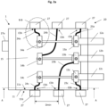
Fig. 2a is a schematic top view of a first embodiment of the cross-bonding box and the monitoring system, where the lid has been removed; -
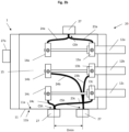
Fig. 2b is a schematic top view of a second embodiment of the cross-bonding box and the monitoring system, where the lid has been removed; -
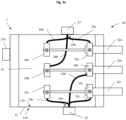
Fig. 2c is a schematic top view of a third embodiment of the cross-bonding box and the monitoring system, where the lid has been removed; -
Fig. 2d is a schematic top view of a fourth embodiment of the cross-bonding box and the monitoring system, where the lid has been removed; -
Fig. 2e is a schematic top view of a fifth embodiment of the cross-bonding box and the monitoring system, where the lid has been removed; -
Fig. 3 shows an enlarged view of the area denoted B-B inFig 2a ; -
Fig. 4 shows a cross sectional side view (along line A-A inFig 2a ) of the cross-bonding box with the connection of the high voltage cables and the position of the heat conduction means; -
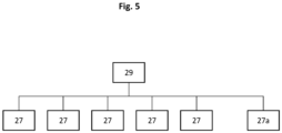
Fig. 5 depicts a flow chart of the thermal sensing units and the signal processing unit. - Shown in
fig. 1 is a prior-art cross-bonding box. The cross-bonding box comprises awaterproof housing 11 with a base section and alid 16, see alsofig 4 . The base section may comprise a bottom plate 11bp and several side plates 11sp extending from the bottom plate 11bp. Thelid 16 may be releasably connected to the side plates on the opposite side of the base plate. The bottom plate 11bp, the side plates 11sp and thelid 16 together define awaterproof housing 11 in which the conductor clamps 13, 14 are located. Moreover, thehousing 11 infig. 1 comprisesopenings high voltage cables 12 from the outside of the housing to the respective conductor clamps 13, 14 inside thehousing 11. The cross-bonding box comprises abase plate 15 secured to the bottom plate 11bp, where earthingbar bridges 6,sheath voltage limiters 3, and inner conductor clamps 14 and outer conductor clamps 13 are mounted to thebase plate 15. - It is now referred to
fig. 2 andfig. 4 . Several parts of the prior artcross bonding box 1 are also shown here, such as the earthing bar bridges 6ab, 6bc, 6ca, outer conductor clamps 13a, 13b, 13c and the inner conductor clamps 14a, 14b, 14c mounted to thebase plate 15, and the bottom plate 11bp and four side plates 11sp of thehousing 11. It should be noted that some parts of the cross-bonding box have been removed fromfig. 2a andfig. 4 , such as thesheath voltage limiter 3. The outer conductor clamps 13 are closer to theopenings - The
monitoring system 20 comprises several heat transfer means 23a, 23b, 23c, 24a, 24b, 24c, 25ab, 25bc, 25ca that are thermally connectable to conductor clamps 13a, 13b, 13c, 14a, 14b and 14c or earthing bar bridges 6ab, 6bc, 6ca when on their own. However,fig 1 through tofig 4 show the heat transfer means 23a, 23b, 23c, 24a, 24b, 24c, 25ab, 25bc, 25ca installed in thecross bonding box 1 where the heat transfer means 23a, 23b, 23c, 24a, 24b, 24c, 25ab, 25bc, 25ca are connected to the conductor clamps 13a, 13b, 13c, 14a, 14b and 14c or the earthing bar bridges 6ab, 6bc, 6ca. - One embodiment of the
monitoring system 20 mounted to thecross-bonding box 1 will now be described with reference tofig 2a . - Here it is shown that the
monitoring system 20 comprises several heat transfer means 23a, 23b, 23c, 24a, 24b, 24c. The heat transfer means 23a, 23b, 23c, 24a, 24b, 24c is thermally connected with a first end of the heat transfer means 23a, 23b, 23c, 24a, 24b, 24c to the conductor clamps 13a, 13b, 13c, 14a, 14b, 14c and with a second end of the heat transfer means 23a, 23b, 23c, 24a, 24b, 24c connected to a housing contact area CSh of theinner surface 11a of thewaterproof housing 11. Preferably, the housing contact area CSh is located on the side plate 11sp. - In a further embodiment, the
monitoring system 20 comprises several heat transfer means 25ab, 25bc, 25ca. The heat transfer means 25ab, 25bc, 25ca is thermally connected with a first end of the heat transfer means 25ab, 25bc, 25ca to the earthing bar bridges 6ab, 6bc, 6ca and with a second end of the heat transfer means 25ab, 25bc, 25ca connected to a housing contact area CSh of theinner surface 11a of thewaterproof housing 11. Preferably, the housing contact area CSh is located on the side plate 11sp. - It is now referred to
fig. 3 . Here it is shown that the heat transfer means 24a is provided with an electrical insulator 26fi between the first end of the heat transfer means and theconductor clamp 14a. The heat transfer means 24a is further provided with an electrical insulator 26se between the second end of the heat transfer means and the inner surface of thewaterproof housing 11a. It is considered sufficient to use only one of the insulators 26fi, 26se to provide electrical insulation. However, it is also possible to use both insulators 26fi, 26se. - It should be noted that even though not shown in
fig. 2a , all heat transfer means infig. 2a are provided with one or two such electric insulators 26fi, 26se. - The electrical insulator 26fi and 26se may be a dielectric material such as polyethylene (PE) or cross-linked polyethylene (XLPE). The electrical insulator is shaped as a thin layer with a thickness of a few micrometers. It is typically a cap insulator. This provides sufficient electrical insulation and at the same time allows thermal conduction.
- The
monitoring system 20 further comprisesthermal sensing units 27 mounted on theouter surface 11b of thewaterproof housing 11 adjacent to the housing contact area CSh of theinner surface 11a, as shown infig 2a . In the present embodiment, there is onethermal sensing unit 27 for conductor clamp. - An additional
thermal sensing unit 27a may be mounted on theouter surface 11b of thewaterproof housing 1. The additional thermal sensing unit will be positioned at a distance from the housing contact area CSh. The purpose of the additionalthermal sensing unit 27a is to provide a reference temperature representing ambient temperature. - Typically, the
waterproof housing 11 is made of a heat conducting material such as a metal. Furthermore, the heat transfer means are typically metal bars, heat pipes or metal wires. - It is now referred to
fig. 2b , in which a second embodiment of themonitoring system 20 is shown. The second embodiment corresponds to the first embodiment described above, and only differences between the first and second embodiment will be described herein. - In
fig. 2b , themonitoring system 20 comprises one heat transfer means for each conductor clamp. The first end of the respective heat transfer means is connected to the individual conductor clamps. However, two heat transfer means have their second ends connected to the same housing contact area CSh of theinner surface 11a of thewaterproof housing 11. Hence, the temperature of the twoconductor clamps common sensing unit 27, the temperature of the two conductor clamps 13b, 14b are monitored by a secondcommon sensing unit 27 and the temperature of the two conductor clamps 13c, 14c are monitored by a thirdcommon sensing unit 27. - It is now referred to
fig. 2c , in which a third embodiment of themonitoring system 20 is shown. The third embodiment corresponds to the first embodiment described above, and only differences between the first and third embodiment will be described herein. - In
fig. 2c , themonitoring system 20 comprises one heat transfer means for each conductor clamp. The first end of the respective heat transfer means is connected to the individual conductor clamps. However, three heat transfer means have their second ends connected to the same housing contact area CSh of theinner surface 11a of thewaterproof housing 11. Hence, the temperature of the threeconductor clamps common sensing unit 27 and the temperature of the three conductor clamps 13b, 13c and 14c are monitored by a secondcommon sensing unit 27. - It is now referred to
fig. 2d , in which a fourth embodiment of themonitoring system 20 is shown. The fourth embodiment corresponds to the first embodiment described above, and only differences between the first and fourth embodiment will be described herein. - In
fig. 2d , themonitoring system 20 comprises one heat transfer means for each conductor clamp. The first end of the respective heat transfer means is connected to the individual conductor clamps. However, all heat transfer means have their second ends connected to the same housing contact area CSh of theinner surface 1 1a of thewaterproof housing 11. Hence, the temperature of the conductor clamps 13a, 13b, 13c, 14a, 14b and 14c are monitored by onecommon sensing unit 27. - It is now referred to
fig. 2e , in which a fifth embodiment of themonitoring system 20 is shown. The fifth embodiment corresponds to the first embodiment described above, and only differences between the first and fifth embodiment will be described herein. - In
fig. 2e , themonitoring system 20 comprises one heat transfer means for each earthing bar bridge. The first end of the respective heat transfer means is connected to the individual earthing bar bridges. All heat transfer means 25ab, 25bc, 25ca have their second ends connected to the same housing contact area CSh of theinner surface 11a of thewaterproof housing 11. Hence, the temperature of the earthing bar bridges 6ab, 6bc, 6ca are monitored by onecommon sensing unit 27. - In a further embodiment of the
monitoring system 20, themonitoring system 20 comprises one heat transfer means for each earthing bar bridge. The first end of the respective heat transfer means is connected to the individual earthing bar bridges. The second end of the respective heat transfer means 25ab, 25bc, 25ca is connected to individual housing contact areas CSh of theinner surface 1 1a of thewaterproof housing 11. Hence, the temperature of each of the earthing bar bridges 6ab, 6bc, 6ca is monitored by anindividual sensing unit 27. - In should further be noted that in an alternative embodiment, the housing contact area CSh for at least one of the
sensing units 27 may be provided on the inner surface of thelid section 16 of thewaterproof housing 11. - The
thermal sensing units 27 shown infig. 2a to 2e are configured to measure a parameter representative of the temperature of the conductor clamps 13a, 13b, 13c, 14a, 14b, 14c or earthing bar bridges 6ab, 6bc, 6ca. Heat at the surface of aconductor clamp inner surface 1 1a of thewaterproof housing 11. The heat is then conducted through thehousing 11 and to theouter surface 11b and into thethermal sensing unit 27. - The individual housing contact areas CSh are spaced apart with a distance Dmin, wherein Dmin is the distance where temperature measurement of a
thermal sensing unit 27 at one housing contact area CSh is not substantially affected by the temperature, or changes in temperature at an adjacent housing contact area CSh. The distance Dmin is determined based on previous experience or based on numerical simulations of heat distribution and or heat flow in the cross-bonding box. - The
thermal sensing unit 27 and additionalthermal sensing unit 27a are in communication with asignal processing unit 29 as shown infig. 5 . Thesignal processing unit 29 is configured to monitor the temperature difference between the temperature measured by athermal sensing unit 27 adjacent to a housing contact area CSh, with the temperature measured by theadditional sensing unit 27a. The additionalthermal sensing unit 27a provides a reference temperature representing undisturbed ambient temperature. Thesignal processing unit 29 triggers an alarm if a critical temperature difference is exceeded. The critical temperature is predetermined and will be tuned or adjusted after themonitoring system 20 has been installed. - Alternatively, the
signal processing unit 29 may be configured to measure relative temperatures differences between thethermal sensing units 27. - When the
signal processing unit 29 triggers an alarm that a critical temperature difference has been exceeded, current transmission incables 12 is reduced or stopped to limit excessive heat generation and irreparable damage to the components of thecross-link box 1. Then the bolts for the conductor clamps 13a, 13b, 13c, 14a, 14b, 14c are re-tightened to minimize contact resistance and heat generation at the conductor clamps. - The
monitoring system 20 may be installed in a newcross-bonding box 1 or retrofitted in across-bonding box 1 that was installed previously. Installing of themonitoring system 20 involves deciding on the basic layout, some of the possible embodiments are shown infig 2a to fig 2b . There is an advantage of choosing a configuration where the heat transfer means are connected to the base of thehousing 11 and not the lid 16 (seefig 4 ) as the system can be installed and tested prior to locking thelid 16 of thecross-bonding box 1. - A first end of the heat transfer means 23a, 23b, 23c, 24a, 24b, 24c or 25ab, 25bc, 25ca is thermally connected to one of the outer or inner conductor clamps 13a, 13b, 13c, 14a, 14b, 14c and one or several heat transfer means 23a, 23b, 23c, 24a, 24b, 24c or 25ab, 25bc, 25ca are thermally connected to a housing contact area CSh.
- When installing the heat transfer means 23a, 23b, 23c, 24a, 24b, 24c or 25ab, 25bc, 25ca, electrical insulator 26fi and or 26se is inserted at the first end and/ or the second end of the heat transfer means 23a, 23b, 23c, 24a, 24b, 24c or 25ab, 25bc, 25ca.
- Connecting heat transfer means 23a, 23b, 23c, 24a, 24b, 24c or 25ab, 25bc, 25ca to a surface must ensure both good thermal conduction and electrical insulation. This requires a method that does not harm the electrical insulator 26fi and 26se. It is therefore preferred to use mechanical means such as clamps or bolts or pins for connecting the heat transfer means 23a, 23b, 23c, 24a, 24b, 24c or 25ab, 25bc, 25ca to the
inner surface 1 1a of thewaterproof housing 11 or a surface of the connector clamps 13, 14 or earthing bar bridges 6. In some cases this may entail preinstalling suitable profiles on theinner surface 11a or shaping first ends or the second ends of the heat transfer means 23a, 23b, 23c, 24a, 24b, 24c or 25ab, 25bc, 25ca to receive clamps or bolts or pins. - On the outside the
housing 11 of thecross-bonding box 1,thermal sensing units 27 are installed. They are positioned adjacent to the housing contact area or areas CSh. The additionalthermal sensing unit 27a is placed away from the housing contact area. Thethermal sensing unit 27 and the additionalthermal sensing unit 27a are spaced at least Dmin apart. Dmin is the distance where temperature measurement of athermal sensing unit 27 at one housing contact area CSh is not disturbed by the temperature, or changes in temperature at an adjacent housing contact area CSh. Dmin is determined prior to installation either by referring to experience from other installations or by using numerical heat simulation methods. - The
thermal sensing units 27 and the additionalthermal sensing unit 27a are connected by wire or wirelessly to thesignal processing unit 29 to monitor the temperature within thecross-bonding box 1. -
- 1 - cross-bonding box with integrity monitoring
- 3 - sheath voltage limiter
- 4 - opening for
high voltage cable 12 - 6 - earthing bar bridge
- 11 - housing of cross-bonding box
- 11a - inner surface of the
waterproof housing 11 - 11b - outer surface of the
waterproof housing 11 - 12 - high voltage cable
- 13 - outer conductor clamp
- 14 - inner conductor clamp
- 15 - base plate
- 16 - removeable lid
- 20 - a monitoring system for installation in a
cross-bonding box 1 - 23 - heat transfer means connected to
outer conductor clamp 13 - 24 - heat transfer means connected to
inner conductor clamp 14 - 25 - heat transfer means connected to earthing
bar bridge 6 - 26fi - electrical insulator at the first end of the heat transfer means,
- 26se - electrical insulator at the second end of the heat transfer mean,
- 27 - thermal sensing unit
- 27a - additional thermal sensing unit
- 29 - signal processing unit
- CSh - housing contact area for thermal conduction means 21, 24
- Dmin - minimum distance between housing contact area CSh
- Tcrit - critical temperature
Claims (15)
- A monitoring system (20) for monitoring of a cross-bonding box (1), characterized in that the monitoring system (20) comprises:- a heat transfer means (23a, 23b, 23c, 24a, 24b, 24c, 25ab, 25bc, 25ca) having a first end and a second end;- a thermal sensing unit (27);wherein the first end of the heat transfer means (23a, 23b, 23c, 24a, 24b, 24c, 25ab, 25bc, 25ca) is thermally connectable to a conductor clamp (13a, 13b, 13c, 14a, 14b, 14c) or an earthing bar bridge (6ab, 6bc, 6ca) located within a waterproof housing (11) of the cross-bonding box (1);wherein the second end of the heat transfer means (23a, 23b, 23c, 24a, 24b, 24c, 25ab, 25bc, 25ca) is thermally connectable to a housing contact area (CSh) of an inner surface (11a) of the waterproof housing (11);wherein the thermal sensing unit (27) is arrangeable on an outer surface (11b) of the waterproof housing (11) adjacent to the housing contact area (CSh) of the inner surface (11a).
- The monitoring system (20) according to claim 1, wherein the monitoring system (20) comprises:- one heat transfer means (23a, 23b, 23c, 24a, 24b, 24c) for each conductor clamp (13a, 13b, 13c, 14a, 14b, 14c) located within the waterproof housing (11);wherein the first end of the respective heat transfer means (23a, 23b, 23c, 24a, 24b, 24c) is thermally connectable to the respective conductor clamps (13a, 13b, 13c, 14a, 14b, 14c);wherein the second end of the respective heat transfer means (23a, 23b, 23c, 24a, 24b, 24c) is thermally connectable to individual housing contact areas (CSh) of the inner surface (11a) of the waterproof housing (11);wherein the individual housing contact areas (CSh) are spaced apart from each other.
- The monitoring system (20) according to claim 1, wherein the monitoring system (20) comprises:- one heat transfer means (23a, 23b, 23c, 24a, 24b, 24c) for each conductor clamp (13a, 13b, 13c, 14a, 14b, 14c) located within the waterproof housing (11);wherein the first end of the respective heat transfer means (23a, 23b, 23c, 24a, 24b, 24c) is thermally connectable to the respective conductor clamps (13a, 13b, 13c, 14a, 14b, 14c);wherein the second ends of two or more heat transfer means (23a, 23b, 23c, 24a, 24b, 24c) are thermally connectable to a common housing contact area (CSh) of the inner surface (1 1a) of the waterproof housing (11);wherein the common housing contact areas (CSh) are spaced apart from each other.
- The monitoring system (20) according to claim 1, wherein the monitoring system (20) comprises:- one heat transfer means (25ab, 25bc, 25ca) for each earthing bar bridge (6ab, 6bc, 6ca) located within the waterproof housing (11);wherein the first end of the respective heat transfer means (25ab, 25bc, 25ca) is thermally connectable to the respective earthing bar bridges (6ab, 6bc, 6ca); wherein the second end of the respective heat transfer means (25ab, 25bc, 25ca) is thermally connectable to individual housing contact areas (CSh) of the inner surface (11a) of the waterproof housing (11);wherein the individual housing contact areas (CSh) are spaced apart from each other.
- The monitoring system (20) according to claim 1, wherein the monitoring system (20) comprises:- one heat transfer means (25ab, 25bc, 25ca) for each earthing bar bridge (6ab, 6bc, 6ca) located within the waterproof housing (11);wherein the first end of the respective heat transfer means (25ab, 25bc, 25ca) is thermally connectable to the respective earthing bar bridges (6ab, 6bc, 6ca); wherein the second ends of two or more heat transfer means (25ab, 25bc, 25ca) are thermally connectable to a common housing contact area (CSh) of the inner surface (11a) of the waterproof housing (11);wherein the common housing contact areas (CSh) are spaced apart from each other.
- The monitoring system (20) according to any one of the above claims, wherein the heat transfer means (23a, 23b, 23c, 24a, 24b, 24c, 25ab, 25bc, 25ca) is a metal bar or a heat pipe.
- The monitoring system (20) according to any one of the above claims, wherein the monitoring system (20) comprises an electrical insulator (26fi, 26se) connected between:- the first end of the heat transfer means (23a, 23b, 23c, 24a, 24b, 24c) and the conductor clamp (13a, 13b, 13c, 14a, 14b, 14c);- the first end of the heat transfer means (25ab, 25bc, 25ca) and the earthing bar bridge (6ab, 6bc, 6ca); and/or- the second end of the heat transfer means (23a, 23b, 23c, 24a, 24b, 24c, 25ab, 25bc, 25ca) and the housing (11).
- The monitoring system (20) according to claim 7, wherein the electrical insulator (26fi, 26se) of the heat transfer means (23a, 23b, 23c, 24a, 24b, 24c, 25ab, 25bc, 25ca) is a dielectric material.
- The monitoring system (20) according to claim 1, wherein the thermal sensing unit (27) is configured to measure a parameter representative of the temperature of the conductor clamp (13a, 13b, 13c, 14a, 14b, 14c) or the earthing bar bridge (6ab, 6bc, 6ca) located within the waterproof housing (11).
- The monitoring system (20) according to claim 1, wherein the monitoring system (20) comprises an additional thermal sensing unit (27a) arrangeable on the outer surface (11b) of the waterproof housing (11) at a distance from the housing contact area (CSh) of the inner surface (11a), wherein the additional thermal sensing unit (27a) is configured to measure an ambient temperature of the housing.
- Method of retrofitting a monitoring system (20) to a cross-bonding box (1) comprising the following steps:- providing a heat transfer means (23a, 23b, 23c, 24a, 24b, 24c, 25ab, 25bc, 25ca) having a first end and a second end;- thermally connecting the first end of the heat transfer means (23a, 23b, 23c, 24a, 24b, 24c, 25ab, 25bc, 25ca) to a conductor clamp (13a, 13b, 13c, 14a, 14b, 14c) or an earthing bar bridge (6ab, 6bc, 6ca);- thermally connecting the second end of the heat transfer means (23a, 23b, 23c, 24a, 24b, 24c, 25ab, 25bc, 25ca) to a housing contact area (CSh) of an inner surface (11a) of the waterproof housing (11);- insulating electrically the conductor clamp (13a, 13b, 13c, 14a, 14b, 14c) or the earthing bar bridge (6ab, 6bc, 6ca) from the housing (11);- arranging a thermal sensing unit (27) on an outer surface (11b) of the waterproof housing (11) adjacent to the housing contact area (CSh) of the inner surface (11a).
- A cross-bonding box (1) for cross-bonding sheaths of a three-phase power cable comprising:- a waterproof housing (11) comprising an inner surface (11a) and an outer surface (11b);- a removeable lid (16) adapted to close the waterproof housing (11);- an outer conductor clamp (13a, 13b, 13c) connectable to a high voltage cable (12a, 12b, 12c);- an inner conductor clamp (14a, 14b, 14c) connectable to a high voltage cable (12a, 12b, 12c);- earthing bar bridges (6ab, 6bc, 6ca) attached to the conductor clamps (13a, 13b, 13c, 14a, 14b, 14c);characterized in that the cross-bonding box comprises a monitoring system (20), wherein the monitoring system (20) comprises:
wherein the conductor clamps (13a, 13b, 13c, 14a, 14b, 14c) and earthing bar bridges (6ab, 6bc, 6ca) are electrically insulated from the waterproof housing (11);- a heat transfer means (23a, 23b, 23c, 24a, 24b, 24c, 25ab, 25bc, 25ca) having a first end and a second end;wherein the first end of the heat transfer means (23a, 23b, 23c, 24a, 24b, 24c, 25ab, 25bc, 25ca) is thermally connected to a conductor clamp (13a, 13b, 13c, 14a, 14b, 14c) or an earthing bar bridge (6ab, 6bc, 6ca) located within the waterproof housing (11);wherein the second end of the heat transfer means (23a, 23b, 23c, 24a, 24b, 24c, 25ab, 25bc, 25ca) is thermally connected to an housing contact area (CSh) of the inner surface (11a) of the waterproof housing (11);- a thermal sensing unit (27) arranged on the outer surface (11b) of the waterproof housing (11) adjacent to the housing contact area (CSh) of the inner surface (11a). - The cross-bonding box (1) according to claim 12, wherein the monitoring system (20) comprises:- one heat transfer means (23a, 23b, 23c, 24a, 24b, 24c) for each conductor clamp (13a, 13b, 13c, 14a, 14b, 14c) located within the waterproof housing (11);wherein the first end of the respective heat transfer means (23a, 23b, 23c, 24a, 24b, 24c) is thermally connected to the respective conductor clamps (13a, 13b, 13c, 14a, 14b, 14c);wherein the second end of the respective heat transfer means (23a, 23b, 23c, 24a, 24b, 24c) is thermally connected to individual housing contact areas (CSh) of the inner surface (11a) of the waterproof housing (11);wherein the individual housing contact areas (CSh) are spaced apart from each other.
- The cross-bonding box (1) with a monitoring system (20) according to claim 12, wherein the monitoring system (20) comprises:- one heat transfer means (23a, 23b, 23c, 24a, 24b, 24c) for each conductor clamp (13a, 13b, 13c, 14a, 14b, 14c) located within the waterproof housing (11);wherein the first end of the respective heat transfer means (23a, 23b, 23c, 24a, 24b, 24c) is thermally connected to the respective conductor clamps (13a, 13b, 13c, 14a, 14b, 14c);wherein the second ends of two or more of the heat transfer means (23a, 23b, 23c, 24a, 24b, 24c) are thermally connected to a common housing contact area (CSh) of the inner surface (11a) of the waterproof housing (11);wherein the common housing contact areas (CSh) are spaced apart from each other.
- The cross-bonding box (1) with a monitoring system (20) according to claim 12, wherein the monitoring system (20) comprises an electrical insulator (26fi, 26se) connected between:- the first end of the heat transfer means (23a, 23b, 23c, 24a, 24b, 24c) and the conductor clamp (13a, 13b, 13c, 14a, 14b, 14c);- the first end of the heat transfer means (25ab, 25bc, 25ca) and the earthing bar bridge (6ab, 6bc, 6ca); and/or- the second end of the heat transfer means (23a, 23b, 23c, 24a, 24b, 24c, 25ab, 25bc, 25ca) and the housing (11).
Priority Applications (2)
| Application Number | Priority Date | Filing Date | Title |
|---|---|---|---|
| ES22305780T ES3058888T3 (en) | 2022-05-25 | 2022-05-25 | Cross-bonding box integrity monitoring |
| EP22305780.3A EP4283267B1 (en) | 2022-05-25 | 2022-05-25 | Cross-bonding box integrity monitoring |
Applications Claiming Priority (1)
| Application Number | Priority Date | Filing Date | Title |
|---|---|---|---|
| EP22305780.3A EP4283267B1 (en) | 2022-05-25 | 2022-05-25 | Cross-bonding box integrity monitoring |
Publications (3)
| Publication Number | Publication Date |
|---|---|
| EP4283267A1 true EP4283267A1 (en) | 2023-11-29 |
| EP4283267C0 EP4283267C0 (en) | 2025-12-24 |
| EP4283267B1 EP4283267B1 (en) | 2025-12-24 |
Family
ID=82156720
Family Applications (1)
| Application Number | Title | Priority Date | Filing Date |
|---|---|---|---|
| EP22305780.3A Active EP4283267B1 (en) | 2022-05-25 | 2022-05-25 | Cross-bonding box integrity monitoring |
Country Status (2)
| Country | Link |
|---|---|
| EP (1) | EP4283267B1 (en) |
| ES (1) | ES3058888T3 (en) |
Citations (5)
| Publication number | Priority date | Publication date | Assignee | Title |
|---|---|---|---|---|
| WO2016008542A1 (en) * | 2014-07-18 | 2016-01-21 | Prysmian S.P.A. | Electrical cable link apparatus and electrical cable system comprising the apparatus |
| US20170313160A1 (en) * | 2014-10-21 | 2017-11-02 | Webasto SE | Heating device with integrated tempoerature sensor |
| WO2019157619A1 (en) | 2018-02-13 | 2019-08-22 | Abb Schweiz Ag | Bushings, system for temperature measurement and method for installing measuring assembly in bushing in switchgear |
| DE202021103459U1 (en) * | 2020-06-29 | 2021-11-04 | Abb Schweiz Ag | Arrangement for measuring the temperature of a cable connection connection of an electric drive |
| EP3910306A1 (en) | 2020-05-13 | 2021-11-17 | Schneider Electric Industries SAS | Electrical apparatus thermal monitoring |
-
2022
- 2022-05-25 ES ES22305780T patent/ES3058888T3/en active Active
- 2022-05-25 EP EP22305780.3A patent/EP4283267B1/en active Active
Patent Citations (5)
| Publication number | Priority date | Publication date | Assignee | Title |
|---|---|---|---|---|
| WO2016008542A1 (en) * | 2014-07-18 | 2016-01-21 | Prysmian S.P.A. | Electrical cable link apparatus and electrical cable system comprising the apparatus |
| US20170313160A1 (en) * | 2014-10-21 | 2017-11-02 | Webasto SE | Heating device with integrated tempoerature sensor |
| WO2019157619A1 (en) | 2018-02-13 | 2019-08-22 | Abb Schweiz Ag | Bushings, system for temperature measurement and method for installing measuring assembly in bushing in switchgear |
| EP3910306A1 (en) | 2020-05-13 | 2021-11-17 | Schneider Electric Industries SAS | Electrical apparatus thermal monitoring |
| DE202021103459U1 (en) * | 2020-06-29 | 2021-11-04 | Abb Schweiz Ag | Arrangement for measuring the temperature of a cable connection connection of an electric drive |
Also Published As
| Publication number | Publication date |
|---|---|
| EP4283267C0 (en) | 2025-12-24 |
| ES3058888T3 (en) | 2026-03-13 |
| EP4283267B1 (en) | 2025-12-24 |
Similar Documents
| Publication | Publication Date | Title |
|---|---|---|
| US12009160B2 (en) | Monitoring method for an electric power transmission device | |
| CN105247750A (en) | Closure | |
| US11143717B2 (en) | Multi-phase sensor module, systems and methods | |
| EP3236272B1 (en) | High-voltage lead-in insulating device | |
| US11183828B1 (en) | Device with health monitoring | |
| US20030040215A1 (en) | Insulated flexible adjustable busbar | |
| JPS6280915A (en) | Cable | |
| KR102124659B1 (en) | busduct joint | |
| US12399196B2 (en) | Terminal sensor array | |
| CN204028285U (en) | A kind of three-phase single-core high-voltage cable on-Line Monitor Device | |
| CN103346512B (en) | A kind of intelligent busway | |
| EP4283267B1 (en) | Cross-bonding box integrity monitoring | |
| KR102404065B1 (en) | System and method for analysing degradation of a underground cable | |
| US20210035711A1 (en) | Underground Layable Power Cable, In Particular, a Submarine Cable | |
| KR20220084498A (en) | Cable for monitoring realtime temperature | |
| EP3752807B1 (en) | Bushings, system for temperature measurement and method for installing measuring assembly in bushing in switchgear | |
| CN102891042A (en) | Generator breaker with SAW sensor | |
| EP4067921B1 (en) | Sheath integrity monitoring | |
| JP3029269B2 (en) | Insulation abnormality detector | |
| Kusmayadi et al. | PROSEDUR PENGECEKAN DAN PENANGANAN HOTSPOT PADA PMS GARDU INDUK 150 KV PEMATANGSIANTAR MENGGUNAKAN METODE THERMOVISION | |
| CN212693098U (en) | Temperature measuring system of high-voltage switch equipment loop connecting structure | |
| EP4345433B1 (en) | Switchgear device | |
| CN109861159B (en) | Composite medium-voltage power cable terminal and installation method thereof | |
| NO343038B1 (en) | Power wiring harness | |
| CN221077869U (en) | Medium-voltage power cable for sensing chip temperature measurement and positioning |
Legal Events
| Date | Code | Title | Description |
|---|---|---|---|
| PUAI | Public reference made under article 153(3) epc to a published international application that has entered the european phase |
Free format text: ORIGINAL CODE: 0009012 |
|
| STAA | Information on the status of an ep patent application or granted ep patent |
Free format text: STATUS: THE APPLICATION HAS BEEN PUBLISHED |
|
| AK | Designated contracting states |
Kind code of ref document: A1 Designated state(s): AL AT BE BG CH CY CZ DE DK EE ES FI FR GB GR HR HU IE IS IT LI LT LU LV MC MK MT NL NO PL PT RO RS SE SI SK SM TR |
|
| STAA | Information on the status of an ep patent application or granted ep patent |
Free format text: STATUS: REQUEST FOR EXAMINATION WAS MADE |
|
| 17P | Request for examination filed |
Effective date: 20240529 |
|
| RBV | Designated contracting states (corrected) |
Designated state(s): AL AT BE BG CH CY CZ DE DK EE ES FI FR GB GR HR HU IE IS IT LI LT LU LV MC MK MT NL NO PL PT RO RS SE SI SK SM TR |
|
| STAA | Information on the status of an ep patent application or granted ep patent |
Free format text: STATUS: EXAMINATION IS IN PROGRESS |
|
| 17Q | First examination report despatched |
Effective date: 20250311 |
|
| RIC1 | Information provided on ipc code assigned before grant |
Ipc: G01K 1/02 20210101AFI20250723BHEP Ipc: G01K 1/16 20060101ALI20250723BHEP Ipc: G01K 1/20 20060101ALI20250723BHEP Ipc: G01K 3/00 20060101ALI20250723BHEP Ipc: G01K 3/14 20060101ALI20250723BHEP Ipc: H01R 9/00 20060101ALI20250723BHEP Ipc: H02G 3/00 20060101ALI20250723BHEP Ipc: H02G 15/00 20060101ALI20250723BHEP Ipc: G01K 1/143 20210101ALI20250723BHEP Ipc: H02G 3/16 20060101ALI20250723BHEP |
|
| GRAP | Despatch of communication of intention to grant a patent |
Free format text: ORIGINAL CODE: EPIDOSNIGR1 |
|
| STAA | Information on the status of an ep patent application or granted ep patent |
Free format text: STATUS: GRANT OF PATENT IS INTENDED |
|
| INTG | Intention to grant announced |
Effective date: 20250905 |
|
| GRAS | Grant fee paid |
Free format text: ORIGINAL CODE: EPIDOSNIGR3 |
|
| GRAA | (expected) grant |
Free format text: ORIGINAL CODE: 0009210 |
|
| STAA | Information on the status of an ep patent application or granted ep patent |
Free format text: STATUS: THE PATENT HAS BEEN GRANTED |
|
| AK | Designated contracting states |
Kind code of ref document: B1 Designated state(s): AL AT BE BG CH CY CZ DE DK EE ES FI FR GB GR HR HU IE IS IT LI LT LU LV MC MK MT NL NO PL PT RO RS SE SI SK SM TR |
|
| REG | Reference to a national code |
Ref country code: CH Ref legal event code: F10 Free format text: ST27 STATUS EVENT CODE: U-0-0-F10-F00 (AS PROVIDED BY THE NATIONAL OFFICE) Effective date: 20251224 Ref country code: GB Ref legal event code: FG4D |
|
| REG | Reference to a national code |
Ref country code: DE Ref legal event code: R096 Ref document number: 602022027364 Country of ref document: DE |
|
| U01 | Request for unitary effect filed |
Effective date: 20260115 |
|
| U07 | Unitary effect registered |
Designated state(s): AT BE BG DE DK EE FI FR IT LT LU LV MT NL PT RO SE SI Effective date: 20260121 |
|
| REG | Reference to a national code |
Ref country code: ES Ref legal event code: FG2A Ref document number: 3058888 Country of ref document: ES Kind code of ref document: T3 Effective date: 20260313 |
|
| PGFP | Annual fee paid to national office [announced via postgrant information from national office to epo] |
Ref country code: NO Payment date: 20260311 Year of fee payment: 5 |
|
| PG25 | Lapsed in a contracting state [announced via postgrant information from national office to epo] |
Ref country code: HR Free format text: LAPSE BECAUSE OF FAILURE TO SUBMIT A TRANSLATION OF THE DESCRIPTION OR TO PAY THE FEE WITHIN THE PRESCRIBED TIME-LIMIT Effective date: 20251224 |
|
| PG25 | Lapsed in a contracting state [announced via postgrant information from national office to epo] |
Ref country code: RS Free format text: LAPSE BECAUSE OF FAILURE TO SUBMIT A TRANSLATION OF THE DESCRIPTION OR TO PAY THE FEE WITHIN THE PRESCRIBED TIME-LIMIT Effective date: 20260324 |
|
| U20 | Renewal fee for the european patent with unitary effect paid |
Year of fee payment: 5 Effective date: 20260422 |
|
| PG25 | Lapsed in a contracting state [announced via postgrant information from national office to epo] |
Ref country code: SM Free format text: LAPSE BECAUSE OF FAILURE TO SUBMIT A TRANSLATION OF THE DESCRIPTION OR TO PAY THE FEE WITHIN THE PRESCRIBED TIME-LIMIT Effective date: 20251224 |
|
| PGFP | Annual fee paid to national office [announced via postgrant information from national office to epo] |
Ref country code: ES Payment date: 20260609 Year of fee payment: 5 |
|
| PG25 | Lapsed in a contracting state [announced via postgrant information from national office to epo] |
Ref country code: PL Free format text: LAPSE BECAUSE OF FAILURE TO SUBMIT A TRANSLATION OF THE DESCRIPTION OR TO PAY THE FEE WITHIN THE PRESCRIBED TIME-LIMIT Effective date: 20251224 |
|
| PGFP | Annual fee paid to national office [announced via postgrant information from national office to epo] |
Ref country code: GB Payment date: 20260414 Year of fee payment: 5 |
|
| PG25 | Lapsed in a contracting state [announced via postgrant information from national office to epo] |
Ref country code: IS Free format text: LAPSE BECAUSE OF FAILURE TO SUBMIT A TRANSLATION OF THE DESCRIPTION OR TO PAY THE FEE WITHIN THE PRESCRIBED TIME-LIMIT Effective date: 20260424 |
|
| PG25 | Lapsed in a contracting state [announced via postgrant information from national office to epo] |
Ref country code: CZ Free format text: LAPSE BECAUSE OF FAILURE TO SUBMIT A TRANSLATION OF THE DESCRIPTION OR TO PAY THE FEE WITHIN THE PRESCRIBED TIME-LIMIT Effective date: 20251224 |
|
| PG25 | Lapsed in a contracting state [announced via postgrant information from national office to epo] |
Ref country code: SK Free format text: LAPSE BECAUSE OF FAILURE TO SUBMIT A TRANSLATION OF THE DESCRIPTION OR TO PAY THE FEE WITHIN THE PRESCRIBED TIME-LIMIT Effective date: 20251224 |