EP4283217A2 - Heat pump system and control method thereof - Google Patents
Heat pump system and control method thereof Download PDFInfo
- Publication number
- EP4283217A2 EP4283217A2 EP23175164.5A EP23175164A EP4283217A2 EP 4283217 A2 EP4283217 A2 EP 4283217A2 EP 23175164 A EP23175164 A EP 23175164A EP 4283217 A2 EP4283217 A2 EP 4283217A2
- Authority
- EP
- European Patent Office
- Prior art keywords
- port
- way valve
- flow path
- throttling device
- heat pump
- Prior art date
- Legal status (The legal status is an assumption and is not a legal conclusion. Google has not performed a legal analysis and makes no representation as to the accuracy of the status listed.)
- Pending
Links
Images



Classifications
-
- F—MECHANICAL ENGINEERING; LIGHTING; HEATING; WEAPONS; BLASTING
- F24—HEATING; RANGES; VENTILATING
- F24F—AIR-CONDITIONING; AIR-HUMIDIFICATION; VENTILATION; USE OF AIR CURRENTS FOR SCREENING
- F24F5/00—Air-conditioning systems or apparatus not covered by F24F1/00 or F24F3/00, e.g. using solar heat or combined with household units such as an oven or water heater
- F24F5/0007—Air-conditioning systems or apparatus not covered by F24F1/00 or F24F3/00, e.g. using solar heat or combined with household units such as an oven or water heater cooling apparatus specially adapted for use in air-conditioning
- F24F5/001—Compression cycle type
-
- F—MECHANICAL ENGINEERING; LIGHTING; HEATING; WEAPONS; BLASTING
- F25—REFRIGERATION OR COOLING; COMBINED HEATING AND REFRIGERATION SYSTEMS; HEAT PUMP SYSTEMS; MANUFACTURE OR STORAGE OF ICE; LIQUEFACTION SOLIDIFICATION OF GASES
- F25B—REFRIGERATION MACHINES, PLANTS OR SYSTEMS; COMBINED HEATING AND REFRIGERATION SYSTEMS; HEAT PUMP SYSTEMS
- F25B13/00—Compression machines, plants or systems, with reversible cycle
-
- F—MECHANICAL ENGINEERING; LIGHTING; HEATING; WEAPONS; BLASTING
- F24—HEATING; RANGES; VENTILATING
- F24F—AIR-CONDITIONING; AIR-HUMIDIFICATION; VENTILATION; USE OF AIR CURRENTS FOR SCREENING
- F24F11/00—Control or safety arrangements
- F24F11/62—Control or safety arrangements characterised by the type of control or by internal processing, e.g. using fuzzy logic, adaptive control or estimation of values
- F24F11/63—Electronic processing
- F24F11/65—Electronic processing for selecting an operating mode
- F24F11/67—Switching between heating and cooling modes
-
- F—MECHANICAL ENGINEERING; LIGHTING; HEATING; WEAPONS; BLASTING
- F25—REFRIGERATION OR COOLING; COMBINED HEATING AND REFRIGERATION SYSTEMS; HEAT PUMP SYSTEMS; MANUFACTURE OR STORAGE OF ICE; LIQUEFACTION SOLIDIFICATION OF GASES
- F25B—REFRIGERATION MACHINES, PLANTS OR SYSTEMS; COMBINED HEATING AND REFRIGERATION SYSTEMS; HEAT PUMP SYSTEMS
- F25B39/00—Evaporators; Condensers
-
- F—MECHANICAL ENGINEERING; LIGHTING; HEATING; WEAPONS; BLASTING
- F25—REFRIGERATION OR COOLING; COMBINED HEATING AND REFRIGERATION SYSTEMS; HEAT PUMP SYSTEMS; MANUFACTURE OR STORAGE OF ICE; LIQUEFACTION SOLIDIFICATION OF GASES
- F25B—REFRIGERATION MACHINES, PLANTS OR SYSTEMS; COMBINED HEATING AND REFRIGERATION SYSTEMS; HEAT PUMP SYSTEMS
- F25B41/00—Fluid-circulation arrangements
- F25B41/20—Disposition of valves, e.g. of on-off valves or flow control valves
-
- F—MECHANICAL ENGINEERING; LIGHTING; HEATING; WEAPONS; BLASTING
- F25—REFRIGERATION OR COOLING; COMBINED HEATING AND REFRIGERATION SYSTEMS; HEAT PUMP SYSTEMS; MANUFACTURE OR STORAGE OF ICE; LIQUEFACTION SOLIDIFICATION OF GASES
- F25B—REFRIGERATION MACHINES, PLANTS OR SYSTEMS; COMBINED HEATING AND REFRIGERATION SYSTEMS; HEAT PUMP SYSTEMS
- F25B41/00—Fluid-circulation arrangements
- F25B41/20—Disposition of valves, e.g. of on-off valves or flow control valves
- F25B41/26—Disposition of valves, e.g. of on-off valves or flow control valves of fluid flow reversing valves
-
- F—MECHANICAL ENGINEERING; LIGHTING; HEATING; WEAPONS; BLASTING
- F25—REFRIGERATION OR COOLING; COMBINED HEATING AND REFRIGERATION SYSTEMS; HEAT PUMP SYSTEMS; MANUFACTURE OR STORAGE OF ICE; LIQUEFACTION SOLIDIFICATION OF GASES
- F25B—REFRIGERATION MACHINES, PLANTS OR SYSTEMS; COMBINED HEATING AND REFRIGERATION SYSTEMS; HEAT PUMP SYSTEMS
- F25B41/00—Fluid-circulation arrangements
- F25B41/30—Expansion means; Dispositions thereof
- F25B41/31—Expansion valves
-
- F—MECHANICAL ENGINEERING; LIGHTING; HEATING; WEAPONS; BLASTING
- F25—REFRIGERATION OR COOLING; COMBINED HEATING AND REFRIGERATION SYSTEMS; HEAT PUMP SYSTEMS; MANUFACTURE OR STORAGE OF ICE; LIQUEFACTION SOLIDIFICATION OF GASES
- F25B—REFRIGERATION MACHINES, PLANTS OR SYSTEMS; COMBINED HEATING AND REFRIGERATION SYSTEMS; HEAT PUMP SYSTEMS
- F25B41/00—Fluid-circulation arrangements
- F25B41/40—Fluid line arrangements
-
- F—MECHANICAL ENGINEERING; LIGHTING; HEATING; WEAPONS; BLASTING
- F25—REFRIGERATION OR COOLING; COMBINED HEATING AND REFRIGERATION SYSTEMS; HEAT PUMP SYSTEMS; MANUFACTURE OR STORAGE OF ICE; LIQUEFACTION SOLIDIFICATION OF GASES
- F25B—REFRIGERATION MACHINES, PLANTS OR SYSTEMS; COMBINED HEATING AND REFRIGERATION SYSTEMS; HEAT PUMP SYSTEMS
- F25B2313/00—Compression machines, plants or systems with reversible cycle not otherwise provided for
- F25B2313/027—Compression machines, plants or systems with reversible cycle not otherwise provided for characterised by the reversing means
- F25B2313/02732—Compression machines, plants or systems with reversible cycle not otherwise provided for characterised by the reversing means using two three-way valves
-
- F—MECHANICAL ENGINEERING; LIGHTING; HEATING; WEAPONS; BLASTING
- F25—REFRIGERATION OR COOLING; COMBINED HEATING AND REFRIGERATION SYSTEMS; HEAT PUMP SYSTEMS; MANUFACTURE OR STORAGE OF ICE; LIQUEFACTION SOLIDIFICATION OF GASES
- F25B—REFRIGERATION MACHINES, PLANTS OR SYSTEMS; COMBINED HEATING AND REFRIGERATION SYSTEMS; HEAT PUMP SYSTEMS
- F25B2313/00—Compression machines, plants or systems with reversible cycle not otherwise provided for
- F25B2313/027—Compression machines, plants or systems with reversible cycle not otherwise provided for characterised by the reversing means
- F25B2313/02741—Compression machines, plants or systems with reversible cycle not otherwise provided for characterised by the reversing means using one four-way valve
-
- F—MECHANICAL ENGINEERING; LIGHTING; HEATING; WEAPONS; BLASTING
- F25—REFRIGERATION OR COOLING; COMBINED HEATING AND REFRIGERATION SYSTEMS; HEAT PUMP SYSTEMS; MANUFACTURE OR STORAGE OF ICE; LIQUEFACTION SOLIDIFICATION OF GASES
- F25B—REFRIGERATION MACHINES, PLANTS OR SYSTEMS; COMBINED HEATING AND REFRIGERATION SYSTEMS; HEAT PUMP SYSTEMS
- F25B2400/00—Component parts or details not otherwise provided for in this subclass
- F25B2400/13—Economisers
-
- F—MECHANICAL ENGINEERING; LIGHTING; HEATING; WEAPONS; BLASTING
- F25—REFRIGERATION OR COOLING; COMBINED HEATING AND REFRIGERATION SYSTEMS; HEAT PUMP SYSTEMS; MANUFACTURE OR STORAGE OF ICE; LIQUEFACTION SOLIDIFICATION OF GASES
- F25B—REFRIGERATION MACHINES, PLANTS OR SYSTEMS; COMBINED HEATING AND REFRIGERATION SYSTEMS; HEAT PUMP SYSTEMS
- F25B2600/00—Control issues
- F25B2600/25—Control of valves
- F25B2600/2507—Flow-diverting valves
Definitions
- the present invention relates to the field of heat pumps, in particular to a heat pump system and a control method thereof.
- the common air-conditioning systems In order to improve the comfort of air-conditioning systems, the common air-conditioning systems have a heating mode.
- the air-conditioning systems with a cooling mode and a heating mode are also referred to as heat pump systems.
- an Enhanced Vapor Injection (EVI) compressor and an economizer located in front of a throttling device are often used, which can increase the system's heating capacity by about 10%.
- EVI Enhanced Vapor Injection
- a heat pump system comprising: a compressor having a compressor inlet and a compressor outlet; a change-over valve configured to selectively connect the compressor inlet and the compressor outlet to a first flow path and a second flow path; a heat-source-side heat exchanger on the first flow path; a user-side heat exchanger on the second flow path; a first branch and a second branch between the first flow path and the second flow path, the first branch being provided with a three-way valve, and the second branch being provided with a first throttling device and a second throttling device, wherein the three-way valve has a first port and a second port for communicating with the first flow path and a third port for communicating with the second flow path; and a third branch connected between a first position between the first throttling device and the second throttling device and the second port of the three-way valve, wherein an economizer is provided on the third branch.
- first throttling device and the second throttling device may be expansion valves.
- the heat pump system may further comprise a controller for controlling the first throttling device and the second throttling device, wherein the controller may be configured to turn off the first throttling device and allow the second throttling device to throttle in the cooling mode, and to turn off the second throttling device and allow the first throttling device to throttle in the heating mode.
- the three-way valve may be a three-way stop valve
- the controller may be configured to control the three-way valve such that the first and second ports of the three-way valve are turned on and the third port is turned off in the cooling mode, and the third and second ports of the three-way valve are turned on and the first port is turned off in the heating mode.
- a control method of a heat pump system is provided, which is for use in a heat pump system according to the first aspect of the invention and optionally including any of the other features described above, the method comprising: turning off the first throttling device and allowing the second throttling device to throttle in a cooling mode such that refrigerant passes through the first port of the three-way valve, the second port of the three-way valve, the economizer and the second throttling device in turn, and turning off the second throttling device and allowing the first throttling device to throttle in a heating mode such that refrigerant passes through the third port of the three-way valve, the second port of the three-way valve, the economizer and the first throttling device in turn.
- the control method of a heat pump system may also be considered as a method of controlling a heat pump system.
- a heat pump system comprising: a compressor having a compressor inlet and a compressor outlet; a change-over valve configured to selectively connect the compressor inlet and the compressor outlet to a first flow path and a second flow path; a heat-source-side heat exchanger on the first flow path; a user-side heat exchanger on the second flow path; a first three-way valve and a second three-way valve arranged in parallel between the first flow path and the second flow path, wherein the first three-way valve has a first port and a second port for communicating with the first flow path and a third port for communicating with the second flow path, and the second three-way valve has a first port and a second port for communicating with the first flow path and a third port for connecting with the second flow path; and an economizer and a throttling device connected in turn between the second port of the first three-way valve and the second port of the second three-way valve.
- the compressor may be an EVI compressor, the EVI compressor may further comprise an air supply port, and the economizer may comprise a port connected to the air supply port.
- the first three-way valve may be configured to only allow refrigerant to flow from its first port to its second port in a cooling mode and to only allow refrigerant to flow from its third port to its second port in a heating mode; the second three-way valve may be configured to only allow refrigerant to flow from its second port to its third port in the cooling mode and to only allow refrigerant to flow from its second port to its first port in the heating mode.
- the throttling device may be an expansion valve.
- the first three-way valve may be a first three-way stop valve and the second three-way valve may be a second three-way stop valve
- the heat pump system may further comprise a controller for controlling the first three-way valve and the second three-way valve, such that the first and second ports of the first three-way valve are turned on and the third port of the first three-way valve is turned off, and the second and third ports of the second three-way valve are turned on and the first port of the second three-way valve is turned off in the cooling mode; and the second and third ports of the first three-way valve are turned on and the first port of the first three-way valve is turned off, and the first and second ports of the second three-way valve are turned on and the third port of the second three-way valve is turned off in the heating mode.
- a control method of a heat pump system is provided, which is for use in a heat pump system according to any of the aspects and optionally including any of the other features described above, the method comprising: turning on the first and second ports of the first three-way valve and turning off the third port of the first three-way valve, and turning on the second and third ports of the second three-way valve and turning off the first port of the second three-way valve in the cooling mode, such that refrigerant passes through the first port of the first three-way valve, the second port of the first three-way valve, the economizer, the throttling device, the second port of the second three-way valve and the third port of the second three-way valve in turn; and turning on the second and third ports of the first three-way valve and turning off the first port of the first three-way valve, and turning on the first and second ports of the second three-way valve and turning off the third port of the second three-way valve in the heating mode, such that refrigerant passes through
- a heat pump system comprising: a compressor having a compressor inlet and a compressor outlet; a change-over valve configured to selectively connect the compressor inlet and the compressor outlet to a first flow path and a second flow path; a heat-source-side heat exchanger on the first flow path; a user-side heat exchanger on the second flow path; a four-way valve arranged between the first flow path and the second flow path, wherein the four-way valve has a first port and a second port for communicating with the first flow path, and a third port and a fourth port for communicating with the second flow path; and an economizer and a throttling device connected in turn between the second port and the fourth port of the four-way valve.
- the compressor may be an EVI compressor, the EVI compressor may further comprise an air supply port, and the economizer may comprise a port connected to the air supply port.
- the four-way valve may be configured to only allow refrigerant to flow from its first port to its second port, and from its fourth port to its third port in the cooling mode, and to only allow refrigerant to flow from its third port to its second port, and from its fourth port to its first port in the heating mode.
- the throttling device may be an expansion valve.
- the four-way valve may be a four-way stop valve
- the heat pump system may further comprise a controller for controlling the four-way valve, such that the first and second ports of the four-way valve are communicated and the third and fourth ports of the four-way valve are communicated in the cooling mode, and the first and fourth ports of the four-way valve are communicated and the second and third ports of the four-way valve are communicated in the heating mode.
- a control method of a heat pump system is provided, which is for use in a heat pump system according to any of the aspects and optionally including any of the other features described above, the method comprising: communicating the first and second ports of the four-way valve and communicating the third and fourth ports of the four-way valve in a cooling mode, such that refrigerant passes through the first port of the four-way valve, the second port of the four-way valve, the economizer, the throttling device, the fourth port of the four-way valve and the third port of the four-way valve in turn; and communicating the first and fourth ports of the four-way valve and communicating the second and third ports of the four-way valve in a heating mode, such that refrigerant passes through the third port of the four-way valve, the second port of the four-way valve, the economizer, the throttling device, the fourth port of the four-way valve and the first port of the four-way valve in turn.
- the control method of a heat pump system is for use in a heat pump
- a heat pump system and a control method thereof according to embodiments of the present invention can be used in both cooling and heating modes.
- the use of multiple-way valves can improve the reliability of the heat pump system.
- FIG 1 shows a local schematic diagram of a heat pump system according to a first embodiment of the present invention.
- the heat pump system 100 comprises: a compressor (not shown) having a compressor inlet and a compressor outlet; a change-over valve (not shown) configured to selectively connect the compressor inlet and the compressor outlet to a first flow path 110 and a second flow path 120; a heat-source-side heat exchanger 111 on the first flow path 110; a user-side heat exchanger 121 on the second flow path 120; a first branch 130 and a second branch 140 between the first flow path 110 and the second flow path 120, the first branch 130 being provided with a three-way valve 150, and the second branch 140 being provided with a first throttling device 141 and a second throttling device 142, wherein the three-way valve 150 has a first port 151 and a second port 152 for communicating with the first flow path 110 and a third port 153 for communicating with the second flow path 120; and a third branch 160 connected between a first position
- the heat pump system utilizes a three-way valve, a first throttling device and a second throttling device to realize the application of an economizer in the cooling and heating modes, thereby improving system capacity and stability.
- a three-way valve can improve system reliability.
- the compressor is an Enhanced Vapor Injection (EVI) compressor, which includes not only the compressor inlet and the compressor outlet, but also an air supply port (not shown).
- the compressor is connected with the heat pump system part shown in FIG 1 through a change-over valve, and the economizer 170 is also connected to the air supply port of the compressor. More specifically, the compressor outlet and the compressor inlet of the EVI compressor are selectively communicated with the first flow path 110 and the second flow path 120 via the change-over valve to execute the cooling and heating modes.
- EVI Enhanced Vapor Injection
- the three-way valve 150 is configured to only allow refrigerant to flow from its first port 151 to its second port 152 in the cooling mode (as shown in FIG 1 ), and to only allow refrigerant to flow from its third port 153 to its second port 152 in the heating mode (as shown in FIG 2 ).
- the first throttling device 141 and the second throttling device 142 are expansion valves, such as electronic expansion valves.
- the heat pump system further comprises a controller (not shown) for controlling the first throttling device 141 and the second throttling device 142.
- the controller is configured to turn off the first throttling device 141 and allow the second throttling device 142 to throttle in the cooling mode, and to turn off the second throttling device 142 and allow the first throttling device 141 to throttle in the heating mode.
- the three-way valve 150 is a three-way stop valve.
- the controller is configured to control the three-way valve 150, such that the first port 151 and the second port 152 of the three-way valve 150 are turned on and the third port 153 of the three-way valve 150 is turned off in the cooling mode, and the third port 153 and the second port 152 of the three-way valve 150 are turned on and the first port 151 of the three-way valve 150 is turned off in the heating mode.
- other suitable types of valves may also be used to achieve the above functions.
- the heat pump system employs a three-way valve and two electronic expansion valves to realize the application of an economizer in the cooling and heating modes.
- the number of valves is reduced, in particular the number of check valves with poor stability, which improves system stability.
- Embodiments of the present invention also provide a control method of a heat pump system, the method comprising: turning off the first throttling device 141 and allowing the second throttling device 142 to throttle in the cooling mode, such that refrigerant passes through the first port 151 of the three-way valve 150, the second port 152 of the three-way valve 150, the economizer 170 and the second throttling device 142 in turn, as shown by the arrows in FIG 1 ; and turning off the second throttling device 142 and allowing the first throttling device 141 to throttle in the heating mode, such that refrigerant passes through the third port 153 of the three-way valve 150, the second port 152 of the three-way valve 150, the economizer 170 and the first throttling device 141 in turn, as shown by the arrows in FIG 2 .
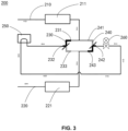
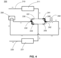
- FIG 3 shows a local schematic diagram of a heat pump system according to a second embodiment of the present invention.
- the heat pump system 200 comprises: a compressor (not shown) having a compressor inlet and a compressor outlet; a change-over valve (not shown) configured to selectively connect the compressor inlet and the compressor outlet to a first flow path 210 and a second flow path 220; a heat-source-side heat exchanger 211 on the first flow path 210; a user-side heat exchanger 221 on the second flow path 220; a first three-way valve 230 and a second three-way valve 240 arranged in parallel between the first flow path 210 and the second flow path 220, wherein the first three-way valve 230 has a first port 231 and a second port 232 for communicating with the first flow path 210 and a third port 233 for communicating with the second flow path 220, and the second three-way valve 240 has a first port 241 and a second port 242 for communicating with the first flow path 210, and
- the heat pump system utilizes two three-way valves arranged in parallel and a throttling device to realize the application of an economizer in the cooling and heating modes, thereby improving system capacity and stability.
- the use of three-way valves can improve system reliability.
- the application of combining a heat pump system according to the embodiments of the present invention with an EVI compressor may be considered.
- the compressor is an Enhanced Vapor
- the first three-way valve 230 is configured to only allow refrigerant to flow from its first port 231 to its second port 232 in the cooling mode (as shown in FIG 3 ), and to only allow refrigerant to flow from its third port 233 to its second port 232 in the heating mode (as shown in FIG 4 ).
- the second three-way valve 240 is configured to only allow refrigerant to flow from its second port 242 to its third port 243 in the cooling mode (as shown in FIG 3 ), and to only allow refrigerant to flow from its second port 242 to its first port 241 in the heating mode (as shown in FIG 4 ).
- the throttling device 260 is an expansion valve, such as an electronic expansion valve.
- the first three-way valve 230 is a first three-way stop valve
- the second three-way valve 240 is a second three-way stop valve
- the heat pump system further comprises a controller (not shown) for controlling the first three-way valve 230 and the second three-way valve 240, such that the first port 231 and the second port 232 of the first three-way valve 230 are turned on and the third port 233 of the first three-way valve 230 is turned off, and the second port 242 and the third port 243 of the second three-way valve 240 are turned on and the first port 241 of the second three-way valve 240 is turned off in the cooling mode; and the second port 232 and the third port 233 of the first three-way valve 230 are turned on and the first port 231 of the first three-way valve 230 is turned off, and the first port 241 and the second port 242 of the second three-way valve 240 are turned on and the third port 243 of the second three-way valve 240 is turned off in the cooling mode; and the
- the heat pump system according to the embodiments of the present invention employs three-way valves arranged in parallel and an electronic expansion valve to realize the application of an economizer in the cooling and heating modes.
- the number of valves is reduced, in particular the number of check valves with poor stability, which improves system stability.
- Embodiments of the present invention also provide a control method of a heat pump system, the method comprising: turning on the first port 231 and the second port 232 of the first three-way valve 230 and turning off the third port 233 of the first three-way valve 230, and turning on the second port 242 and the third port 243 of the second three-way valve 240 and turning off the first port 241 of the second three-way valve 240 in the cooling mode, such that refrigerant passes through the first port 231 of the first three-way valve 230, the second port 232 of the first three-way valve 230, the economizer 250, the throttling device 260, the second port 242 of the second three-way valve 240 and the third port 243 of the second three-way valve 240 in turn, as shown by the arrows in FIG 3 ; and turning on the second port 232 and the third port 233 of the first three-way valve 230 and turning off the first port 231 of the first three-way valve 230, and turning on the
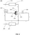
- FIG 5 shows a local schematic diagram of a heat pump system according to a third embodiment of the present invention.
- the heat pump system 300 comprises: a compressor (not shown) comprising a compressor inlet and a compressor outlet; a change-over valve (not shown) configured to selectively connect the compressor inlet and the compressor outlet to a first flow path 310 and a second flow path 320; a heat-source-side heat exchanger 311 on the first flow path 310; a user-side heat exchanger 321 on the second flow path 320; a four-way valve 330 arranged between the first flow path 310 and the second flow path 320, wherein the four-way valve 330 has a first port 331 and a second port 332 for communicating with the first flow path 310, and a third port 333 and a fourth port 334 for communicating with the second flow path 320; and an economizer 340 and a throttling device 350 connected in turn between the second port 332 and the fourth port 334 of the four-way valve 330
- the heat pump system utilizes a four-way valve and a throttling device to realize the application of an economizer in the cooling and heating modes, thereby improving system capacity and stability.
- the use of the three-way valve can improve system reliability.
- the compressor is an Enhanced Vapor Injection (EVI) compressor, which includes not only the compressor inlet and the compressor outlet, but also an air supply port (not shown).
- the compressor is connected with the heat pump system part shown in FIG 5 through a change-over valve, and the economizer 340 is also connected to the air supply port of the compressor. More specifically, the compressor outlet and the compressor inlet of the EVI compressor are selectively communicated with the first flow path 310 and the second flow path 320 via the change-over valve to execute the cooling and heating modes.
- EVI Enhanced Vapor Injection
- the four-way valve 330 is configured to only allow refrigerant to flow from its first port 331 to its second port 332 and from its fourth port 334 to its third port 333 in the cooling mode (as shown in FIG 5 ), and to only allow refrigerant to flow from its third port 333 to its second port 332 and from its fourth port 334 to its first port 331 in the heating mode (as shown in FIG 6 ).
- the throttling device 350 is an expansion valve, such as an electronic expansion valve.
- the four-way valve 330 is a four-way stop valve
- the heat pump system further comprises a controller (not shown) for controlling the four-way valve 330, such that the first port 331 and the second port 332 of the four-way valve 330 are communicated and the third port 333 and the fourth port 334 of the four-way valve 330 are communicated in the cooling mode, and that the first port 331 and the fourth port 334 of the four-way valve 330 are communicated and the second port 332 and the third port 333 of the four-way valve 330 are communicated in the heating mode.
- other suitable types of valves may also be used to achieve the above functions.
Landscapes
- Engineering & Computer Science (AREA)
- Physics & Mathematics (AREA)
- General Engineering & Computer Science (AREA)
- Mechanical Engineering (AREA)
- Thermal Sciences (AREA)
- Signal Processing (AREA)
- Chemical & Material Sciences (AREA)
- Combustion & Propulsion (AREA)
- Fluid Mechanics (AREA)
- Fuzzy Systems (AREA)
- Mathematical Physics (AREA)
- Life Sciences & Earth Sciences (AREA)
- Sustainable Development (AREA)
- Compression-Type Refrigeration Machines With Reversible Cycles (AREA)
Abstract
Description
- The present invention relates to the field of heat pumps, in particular to a heat pump system and a control method thereof.
- In order to improve the comfort of air-conditioning systems, the common air-conditioning systems have a heating mode. The air-conditioning systems with a cooling mode and a heating mode are also referred to as heat pump systems. In order to improve the heat pump system's capacity in the heating mode, an Enhanced Vapor Injection (EVI) compressor and an economizer located in front of a throttling device are often used, which can increase the system's heating capacity by about 10%.
- In order to enable the EVI compressor and the economizer to also function in the cooling mode, i.e., to improve the system's capacity in the cooling mode, a complex pipeline structure with four check valves and one expansion valve is usually used, which challenges the reliability of the check valves.
- An object of the present invention is to solve or at least alleviate problems existing in the prior art.
- According to a first aspect of the present invention, a heat pump system is provided, comprising: a compressor having a compressor inlet and a compressor outlet; a change-over valve configured to selectively connect the compressor inlet and the compressor outlet to a first flow path and a second flow path; a heat-source-side heat exchanger on the first flow path; a user-side heat exchanger on the second flow path; a first branch and a second branch between the first flow path and the second flow path, the first branch being provided with a three-way valve, and the second branch being provided with a first throttling device and a second throttling device, wherein the three-way valve has a first port and a second port for communicating with the first flow path and a third port for communicating with the second flow path; and a third branch connected between a first position between the first throttling device and the second throttling device and the second port of the three-way valve, wherein an economizer is provided on the third branch.
- Optionally, the compressor may be an EVI compressor, the EVI compressor may further comprise an air supply port, and the economizer may comprise a port connected to the air supply port.
- Optionally, the three-way valve may be configured to only allow refrigerant to flow from its first port to its second port in a cooling mode, and to only allow refrigerant to flow from its third port to its second port in a heating mode.
- Optionally, the first throttling device and the second throttling device may be expansion valves.
- Optionally, the heat pump system may further comprise a controller for controlling the first throttling device and the second throttling device, wherein the controller may be configured to turn off the first throttling device and allow the second throttling device to throttle in the cooling mode, and to turn off the second throttling device and allow the first throttling device to throttle in the heating mode.
- Optionally, the three-way valve may be a three-way stop valve, and the controller may be configured to control the three-way valve such that the first and second ports of the three-way valve are turned on and the third port is turned off in the cooling mode, and the third and second ports of the three-way valve are turned on and the first port is turned off in the heating mode.
- According to a second aspect of the present invention, a control method of a heat pump system is provided, which is for use in a heat pump system according to the first aspect of the invention and optionally including any of the other features described above, the method comprising: turning off the first throttling device and allowing the second throttling device to throttle in a cooling mode such that refrigerant passes through the first port of the three-way valve, the second port of the three-way valve, the economizer and the second throttling device in turn, and turning off the second throttling device and allowing the first throttling device to throttle in a heating mode such that refrigerant passes through the third port of the three-way valve, the second port of the three-way valve, the economizer and the first throttling device in turn. The control method of a heat pump system may also be considered as a method of controlling a heat pump system.
- According to a third aspect of the present invention, a heat pump system is provided, comprising: a compressor having a compressor inlet and a compressor outlet; a change-over valve configured to selectively connect the compressor inlet and the compressor outlet to a first flow path and a second flow path; a heat-source-side heat exchanger on the first flow path; a user-side heat exchanger on the second flow path; a first three-way valve and a second three-way valve arranged in parallel between the first flow path and the second flow path, wherein the first three-way valve has a first port and a second port for communicating with the first flow path and a third port for communicating with the second flow path, and the second three-way valve has a first port and a second port for communicating with the first flow path and a third port for connecting with the second flow path; and an economizer and a throttling device connected in turn between the second port of the first three-way valve and the second port of the second three-way valve.
- Optionally, the compressor may be an EVI compressor, the EVI compressor may further comprise an air supply port, and the economizer may comprise a port connected to the air supply port.
- Optionally, the first three-way valve may be configured to only allow refrigerant to flow from its first port to its second port in a cooling mode and to only allow refrigerant to flow from its third port to its second port in a heating mode; the second three-way valve may be configured to only allow refrigerant to flow from its second port to its third port in the cooling mode and to only allow refrigerant to flow from its second port to its first port in the heating mode.
- Optionally, the throttling device may be an expansion valve.
- Optionally, the first three-way valve may be a first three-way stop valve and the second three-way valve may be a second three-way stop valve, wherein the heat pump system may further comprise a controller for controlling the first three-way valve and the second three-way valve, such that the first and second ports of the first three-way valve are turned on and the third port of the first three-way valve is turned off, and the second and third ports of the second three-way valve are turned on and the first port of the second three-way valve is turned off in the cooling mode; and the second and third ports of the first three-way valve are turned on and the first port of the first three-way valve is turned off, and the first and second ports of the second three-way valve are turned on and the third port of the second three-way valve is turned off in the heating mode.
- According to a fourth aspect of the present invention, a control method of a heat pump system is provided, which is for use in a heat pump system according to any of the aspects and optionally including any of the other features described above, the method comprising: turning on the first and second ports of the first three-way valve and turning off the third port of the first three-way valve, and turning on the second and third ports of the second three-way valve and turning off the first port of the second three-way valve in the cooling mode, such that refrigerant passes through the first port of the first three-way valve, the second port of the first three-way valve, the economizer, the throttling device, the second port of the second three-way valve and the third port of the second three-way valve in turn; and turning on the second and third ports of the first three-way valve and turning off the first port of the first three-way valve, and turning on the first and second ports of the second three-way valve and turning off the third port of the second three-way valve in the heating mode, such that refrigerant passes through the third port of the first three-way valve, the second port of the first three-way valve, the economizer, the throttling device, the second port of the second three-way valve and the first port of the second three-way valve in turn. The control method of a heat pump system may also be considered as a method of controlling a heat pump system.
- According to a fifth aspect of the present invention, a heat pump system is provided, comprising: a compressor having a compressor inlet and a compressor outlet; a change-over valve configured to selectively connect the compressor inlet and the compressor outlet to a first flow path and a second flow path; a heat-source-side heat exchanger on the first flow path; a user-side heat exchanger on the second flow path; a four-way valve arranged between the first flow path and the second flow path, wherein the four-way valve has a first port and a second port for communicating with the first flow path, and a third port and a fourth port for communicating with the second flow path; and an economizer and a throttling device connected in turn between the second port and the fourth port of the four-way valve.
- Optionally, the compressor may be an EVI compressor, the EVI compressor may further comprise an air supply port, and the economizer may comprise a port connected to the air supply port.
- Optionally, the four-way valve may be configured to only allow refrigerant to flow from its first port to its second port, and from its fourth port to its third port in the cooling mode, and to only allow refrigerant to flow from its third port to its second port, and from its fourth port to its first port in the heating mode.
- Optionally, the throttling device may be an expansion valve.
- Optionally, the four-way valve may be a four-way stop valve, and the heat pump system may further comprise a controller for controlling the four-way valve, such that the first and second ports of the four-way valve are communicated and the third and fourth ports of the four-way valve are communicated in the cooling mode, and the first and fourth ports of the four-way valve are communicated and the second and third ports of the four-way valve are communicated in the heating mode.
- According to a sixth aspect of the present invention, a control method of a heat pump system is provided, which is for use in a heat pump system according to any of the aspects and optionally including any of the other features described above, the method comprising: communicating the first and second ports of the four-way valve and communicating the third and fourth ports of the four-way valve in a cooling mode, such that refrigerant passes through the first port of the four-way valve, the second port of the four-way valve, the economizer, the throttling device, the fourth port of the four-way valve and the third port of the four-way valve in turn; and communicating the first and fourth ports of the four-way valve and communicating the second and third ports of the four-way valve in a heating mode, such that refrigerant passes through the third port of the four-way valve, the second port of the four-way valve, the economizer, the throttling device, the fourth port of the four-way valve and the first port of the four-way valve in turn. The control method of a heat pump system may also be considered as a method of controlling a heat pump system.
- A heat pump system and a control method thereof according to embodiments of the present invention can be used in both cooling and heating modes. In addition, the use of multiple-way valves can improve the reliability of the heat pump system.
- With reference to the accompanying drawings, the present invention will become easier to understand. Those skilled in the art would readily appreciate that these drawings are for the purpose of illustration, and are not intended to limit the protection scope of the present invention. In addition, in the figures, similar numerals are used to denote similar components, where:
-
FIG 1 shows a local schematic diagram of a first embodiment of a heat pump system according to the present invention in a cooling mode; -
FIG 2 shows a local schematic diagram of the first embodiment of a heat pump system according to the present invention in a heating mode; -
FIG 3 shows a local schematic diagram of a second embodiment of a heat pump system according to the present invention in a cooling mode; -
FIG 4 shows a local schematic diagram of the second embodiment of a heat pump system according to the present invention in a heating mode; -
FIG 5 shows a local schematic diagram of a third embodiment of a heat pump system according to the present invention in a cooling mode; and -
FIG 6 shows a local schematic diagram of the third embodiment of a heat pump system according to the present invention in a heating mode. -
FIG 1 shows a local schematic diagram of a heat pump system according to a first embodiment of the present invention. Theheat pump system 100 comprises: a compressor (not shown) having a compressor inlet and a compressor outlet; a change-over valve (not shown) configured to selectively connect the compressor inlet and the compressor outlet to afirst flow path 110 and asecond flow path 120; a heat-source-side heat exchanger 111 on thefirst flow path 110; a user-side heat exchanger 121 on thesecond flow path 120; afirst branch 130 and asecond branch 140 between thefirst flow path 110 and thesecond flow path 120, thefirst branch 130 being provided with a three-way valve 150, and thesecond branch 140 being provided with afirst throttling device 141 and asecond throttling device 142, wherein the three-way valve 150 has afirst port 151 and asecond port 152 for communicating with thefirst flow path 110 and athird port 153 for communicating with thesecond flow path 120; and athird branch 160 connected between afirst position 143 between thefirst throttling device 141 and thesecond throttling device 142, and thesecond port 152 of the three-way valve 150, wherein aneconomizer 170 is provided on thethird branch 160. The heat pump system according to the embodiments of the present invention utilizes a three-way valve, a first throttling device and a second throttling device to realize the application of an economizer in the cooling and heating modes, thereby improving system capacity and stability. In addition, the use of a three-way valve can improve system reliability. - The application of combining a heat pump system according to the embodiments of the present invention with an EVI compressor may be considered. The compressor is an Enhanced Vapor Injection (EVI) compressor, which includes not only the compressor inlet and the compressor outlet, but also an air supply port (not shown). The compressor is connected with the heat pump system part shown in
FIG 1 through a change-over valve, and theeconomizer 170 is also connected to the air supply port of the compressor. More specifically, the compressor outlet and the compressor inlet of the EVI compressor are selectively communicated with thefirst flow path 110 and thesecond flow path 120 via the change-over valve to execute the cooling and heating modes. - In some embodiments, the three-
way valve 150 is configured to only allow refrigerant to flow from itsfirst port 151 to itssecond port 152 in the cooling mode (as shown inFIG 1 ), and to only allow refrigerant to flow from itsthird port 153 to itssecond port 152 in the heating mode (as shown inFIG 2 ). In some embodiments, thefirst throttling device 141 and thesecond throttling device 142 are expansion valves, such as electronic expansion valves. In some embodiments, the heat pump system further comprises a controller (not shown) for controlling thefirst throttling device 141 and thesecond throttling device 142. The controller is configured to turn off thefirst throttling device 141 and allow thesecond throttling device 142 to throttle in the cooling mode, and to turn off thesecond throttling device 142 and allow thefirst throttling device 141 to throttle in the heating mode. In some embodiments, the three-way valve 150 is a three-way stop valve. The controller is configured to control the three-way valve 150, such that thefirst port 151 and thesecond port 152 of the three-way valve 150 are turned on and thethird port 153 of the three-way valve 150 is turned off in the cooling mode, and thethird port 153 and thesecond port 152 of the three-way valve 150 are turned on and thefirst port 151 of the three-way valve 150 is turned off in the heating mode. In some embodiments, other suitable types of valves may also be used to achieve the above functions. - The heat pump system according to the embodiments of the present invention employs a three-way valve and two electronic expansion valves to realize the application of an economizer in the cooling and heating modes. Compared to the existing structure with four check valves and a single expansion valve, the number of valves is reduced, in particular the number of check valves with poor stability, which improves system stability.
- Embodiments of the present invention also provide a control method of a heat pump system, the method comprising: turning off the
first throttling device 141 and allowing thesecond throttling device 142 to throttle in the cooling mode, such that refrigerant passes through thefirst port 151 of the three-way valve 150, thesecond port 152 of the three-way valve 150, theeconomizer 170 and thesecond throttling device 142 in turn, as shown by the arrows inFIG 1 ; and turning off thesecond throttling device 142 and allowing thefirst throttling device 141 to throttle in the heating mode, such that refrigerant passes through thethird port 153 of the three-way valve 150, thesecond port 152 of the three-way valve 150, theeconomizer 170 and thefirst throttling device 141 in turn, as shown by the arrows inFIG 2 . It can thus be seen that in the control method of a heat pump system according to the embodiment illustrated inFIGS. 1-2 , the application of an economizer in the cooling and heating modes is realized through the use of a three-way valve and two throttling devices, thereby improving system efficiency and stability. -
FIG 3 shows a local schematic diagram of a heat pump system according to a second embodiment of the present invention. Theheat pump system 200 comprises: a compressor (not shown) having a compressor inlet and a compressor outlet; a change-over valve (not shown) configured to selectively connect the compressor inlet and the compressor outlet to afirst flow path 210 and asecond flow path 220; a heat-source-side heat exchanger 211 on thefirst flow path 210; a user-side heat exchanger 221 on thesecond flow path 220; a first three-way valve 230 and a second three-way valve 240 arranged in parallel between thefirst flow path 210 and thesecond flow path 220, wherein the first three-way valve 230 has afirst port 231 and asecond port 232 for communicating with thefirst flow path 210 and athird port 233 for communicating with thesecond flow path 220, and the second three-way valve 240 has afirst port 241 and asecond port 242 for communicating with thefirst flow path 210, and athird port 243 for communicating with thesecond flow path 220; and aneconomizer 250 and athrottling device 260 connected in turn between thesecond port 232 of the first three-way valve 230 and thesecond port 242 of the second three-way valve 240. The heat pump system according to the embodiments of the present invention utilizes two three-way valves arranged in parallel and a throttling device to realize the application of an economizer in the cooling and heating modes, thereby improving system capacity and stability. In addition, the use of three-way valves can improve system reliability. - The application of combining a heat pump system according to the embodiments of the present invention with an EVI compressor may be considered. The compressor is an Enhanced Vapor
- Injection (EVI) compressor, which includes not only the compressor inlet and the compressor outlet, but also an air supply port (not shown). The compressor is connected with the heat pump system part shown in
FIG 3 through a change-over valve, and theeconomizer 250 is also connected to the air supply port of the compressor. More specifically, the compressor outlet and the compressor inlet of the EVI compressor are selectively communicated with thefirst flow path 210 and thesecond flow path 220 via the change-over valve to execute the cooling and heating modes. - In some embodiments, the first three-
way valve 230 is configured to only allow refrigerant to flow from itsfirst port 231 to itssecond port 232 in the cooling mode (as shown inFIG 3 ), and to only allow refrigerant to flow from itsthird port 233 to itssecond port 232 in the heating mode (as shown inFIG 4 ). The second three-way valve 240 is configured to only allow refrigerant to flow from itssecond port 242 to itsthird port 243 in the cooling mode (as shown inFIG 3 ), and to only allow refrigerant to flow from itssecond port 242 to itsfirst port 241 in the heating mode (as shown inFIG 4 ). In some embodiments, thethrottling device 260 is an expansion valve, such as an electronic expansion valve. In some embodiments, the first three-way valve 230 is a first three-way stop valve, and the second three-way valve 240 is a second three-way stop valve. Wherein, the heat pump system further comprises a controller (not shown) for controlling the first three-way valve 230 and the second three-way valve 240, such that thefirst port 231 and thesecond port 232 of the first three-way valve 230 are turned on and thethird port 233 of the first three-way valve 230 is turned off, and thesecond port 242 and thethird port 243 of the second three-way valve 240 are turned on and thefirst port 241 of the second three-way valve 240 is turned off in the cooling mode; and thesecond port 232 and thethird port 233 of the first three-way valve 230 are turned on and thefirst port 231 of the first three-way valve 230 is turned off, and thefirst port 241 and thesecond port 242 of the second three-way valve 240 are turned on and thethird port 243 of the second three-way valve 240 is turned off in the heating mode. In some embodiments, other suitable types of valves may also be used to achieve the above functions. - The heat pump system according to the embodiments of the present invention employs three-way valves arranged in parallel and an electronic expansion valve to realize the application of an economizer in the cooling and heating modes. Compared to the existing structure with four check valves and a single expansion valve, the number of valves is reduced, in particular the number of check valves with poor stability, which improves system stability.
- Embodiments of the present invention also provide a control method of a heat pump system, the method comprising: turning on the first port 231 and the second port 232 of the first three-way valve 230 and turning off the third port 233 of the first three-way valve 230, and turning on the second port 242 and the third port 243 of the second three-way valve 240 and turning off the first port 241 of the second three-way valve 240 in the cooling mode, such that refrigerant passes through the first port 231 of the first three-way valve 230, the second port 232 of the first three-way valve 230, the economizer 250, the throttling device 260, the second port 242 of the second three-way valve 240 and the third port 243 of the second three-way valve 240 in turn, as shown by the arrows in
FIG 3 ; and turning on the second port 232 and the third port 233 of the first three-way valve 230 and turning off the first port 231 of the first three-way valve 230, and turning on the first port 241 and the second port 242 of the second three-way valve 240 and turning off the third port 243 of the second three-way valve 240 in the heating mode, such that refrigerant passes through the third port 233 of the first three-way valve 230, the second port 232 of the first three-way valve 230, the economizer 250, the throttling device 260, the second port 242 of the second three-way valve 240 and the first port 241 of the second three-way valve 240 in turn, as shown by the arrows inFIG 4 . It can thus be seen that in the control method of a heat pump system according to the embodiment illustrated inFIGS. 3-4 , the application of an economizer in the cooling and heating modes is realized through the use of three-way valves arranged in parallel and a throttling device, thereby improving system efficiency and stability. -
FIG 5 shows a local schematic diagram of a heat pump system according to a third embodiment of the present invention. Theheat pump system 300 comprises: a compressor (not shown) comprising a compressor inlet and a compressor outlet; a change-over valve (not shown) configured to selectively connect the compressor inlet and the compressor outlet to afirst flow path 310 and asecond flow path 320; a heat-source-side heat exchanger 311 on thefirst flow path 310; a user-side heat exchanger 321 on thesecond flow path 320; a four-way valve 330 arranged between thefirst flow path 310 and thesecond flow path 320, wherein the four-way valve 330 has afirst port 331 and asecond port 332 for communicating with thefirst flow path 310, and athird port 333 and afourth port 334 for communicating with thesecond flow path 320; and aneconomizer 340 and athrottling device 350 connected in turn between thesecond port 332 and thefourth port 334 of the four-way valve 330. The heat pump system according to the embodiments of the present invention utilizes a four-way valve and a throttling device to realize the application of an economizer in the cooling and heating modes, thereby improving system capacity and stability. In addition, the use of the three-way valve can improve system reliability. - The application of combining a heat pump system according to the embodiments of the present invention with an EVI compressor may be considered. The compressor is an Enhanced Vapor Injection (EVI) compressor, which includes not only the compressor inlet and the compressor outlet, but also an air supply port (not shown). The compressor is connected with the heat pump system part shown in
FIG 5 through a change-over valve, and theeconomizer 340 is also connected to the air supply port of the compressor. More specifically, the compressor outlet and the compressor inlet of the EVI compressor are selectively communicated with thefirst flow path 310 and thesecond flow path 320 via the change-over valve to execute the cooling and heating modes. - In some embodiments, the four-
way valve 330 is configured to only allow refrigerant to flow from itsfirst port 331 to itssecond port 332 and from itsfourth port 334 to itsthird port 333 in the cooling mode (as shown inFIG 5 ), and to only allow refrigerant to flow from itsthird port 333 to itssecond port 332 and from itsfourth port 334 to itsfirst port 331 in the heating mode (as shown inFIG 6 ). In some embodiments, thethrottling device 350 is an expansion valve, such as an electronic expansion valve. In some embodiments, the four-way valve 330 is a four-way stop valve, and the heat pump system further comprises a controller (not shown) for controlling the four-way valve 330, such that thefirst port 331 and thesecond port 332 of the four-way valve 330 are communicated and thethird port 333 and thefourth port 334 of the four-way valve 330 are communicated in the cooling mode, and that thefirst port 331 and thefourth port 334 of the four-way valve 330 are communicated and thesecond port 332 and thethird port 333 of the four-way valve 330 are communicated in the heating mode. In some embodiments, other suitable types of valves may also be used to achieve the above functions. - The heat pump system according to the embodiments of the present invention employs a four-way valve and an electronic expansion valve to realize the application of an economizer in the cooling and heating modes. Compared to the existing structure with four check valves and a single expansion valve, the number of valves is reduced, in particular the number of check valves with poor stability, which improves system stability.
- Embodiments of the present invention also provide a control method of a heat pump system, the method comprising: communicating the
first port 331 and thesecond port 332 of the four-way valve 330, and communicating thethird port 333 and thefourth port 334 of the four-way valve 330 in the cooling mode, such that refrigerant passes through thefirst port 331 of the four-way valve 330, thesecond port 332 of the four-way valve 330, theeconomizer 340, thethrottling device 350, thefourth port 334 of the four-way valve 330, and thethird port 333 of the four-way valve 330 in turn, as shown by the arrows inFIG 5 ; and communicating thefirst port 331 and thefourth port 334 of the four-way valve 330, and communicating thesecond port 332 and thethird port 333 of the four-way valve 330 in the heating mode, such that refrigerant passes through thethird port 333 of the four-way valve 330, thesecond port 332 of the four-way valve 330, theeconomizer 340, thethrottling device 350, thefourth port 334 of the four-way valve 330 and thefirst port 331 of the four-way valve 330 in turn, as shown by the arrows inFIG 6 . It can thus be seen that in the control method of a heat pump system according to the embodiments illustrated inFIG 5-6 , the application of an economizer in the cooling and heating modes is realized through the use of a four-way valve and a throttling device, thereby improving system efficiency and stability. - The specific embodiments of the present invention described above are merely for a clearer description of the principles of the present invention, in which individual components are clearly shown or described to make the principles of the present invention easier to understand. Various modifications or changes may be easily made by those skilled in the art without departing from the scope of the present invention as defined in the appended claims. It should therefore be understood that these modifications or changes shall be included within the scope of the patent protection of the present application as defined by the appended claims.
Claims (15)
- A heat pump system (100), comprising:a compressor having a compressor inlet and a compressor outlet;a change-over valve configured to selectively connect the compressor inlet and the compressor outlet to a first flow path (110) and a second flow path (120);a heat-source-side heat exchanger (111) on the first flow path (110);a user-side heat exchanger (121) on the second flow path (120);a first branch (130) and a second branch (140) between the first flow path (110) and the second flow path (120), the first branch (130) being provided with a three-way valve (150), and the second branch (140) being provided with a first throttling device (141) and a second throttling device (142), wherein the three-way valve (150) has a first port (151) and a second port (152) for communicating with the first flow path (110) and a third port (153) for communicating with the second flow path (120); anda third branch (160) connected between a first position (143) between the first throttling device (141) and the second throttling device (142) and the second port (152) of the three-way valve (150), wherein an economizer (170) is provided on the third branch (160).
- The heat pump system (100) according to claim 1, wherein the compressor is an Enhanced Vapor Injection compressor, the Enhanced Vapor Injection compressor comprises an air supply port, and the economizer (170) comprises a port connected to the air supply port.
- The heat pump system (100) according to claim 1 or 2, wherein the three-way valve (150) is configured to only allow refrigerant to flow from its first port (151) to its second port (152) in a cooling mode, and to only allow refrigerant to flow from its third port (153) to its second port (152) in a heating mode; and/or
wherein the first throttling device (141) and the second throttling device (142) are expansion valves. - The heat pump system (100) according to claim 1, 2, or 3, wherein the heat pump system (100) comprises a controller for controlling the first throttling device (141) and the second throttling device (142), wherein the controller is configured to turn off the first throttling device (141) and allow the second throttling device (142) to throttle in the cooling mode, and to turn off the second throttling device (142) and allow the first throttling device (141) to throttle in the heating mode; and
optionally wherein the three-way valve (150) is a three-way stop valve, and the controller is configured to control the three-way valve (150) such that the first (151) and second (152) ports of the three-way valve (150) are turned on and the third port (153) is turned off in the cooling mode, and the third (153) and second (152) ports of the three-way valve (150) are turned on and the first port (151) is turned off in the heating mode. - A control method of a heat pump system (100) for use in a heat pump system (100) according to any of claims 1 to 4, the method comprising:
turning off the first throttling device (141) and allowing the second throttling device (142) to throttle in a cooling mode such that refrigerant passes through the first port (151) of the three-way valve (150), the second port (152) of the three-way valve (150), the economizer (170) and the second throttling device (142) in turn, and turning off the second throttling device (142) and allowing the first throttling device (141) to throttle in a heating mode such that refrigerant passes through the third port (153) of the three-way valve (150), the second port (152) of the three-way valve (150), the economizer (170) and the first throttling device (141) in turn. - A heat pump system (200), comprising:a compressor having a compressor inlet and a compressor outlet;a change-over valve configured to selectively connect the compressor inlet and the compressor outlet to a first flow path (210) and a second flow path (220);a heat-source-side heat exchanger (211) on the first flow path (210);a user-side heat exchanger (221) on the second flow path (220);a first three-way valve (230) and a second three-way valve (240) arranged in parallel between the first flow path (210) and the second flow path (220), wherein the first three-way valve (230) has a first port (231) and a second port (232) for communicating with the first flow path (210) and a third port (233) for communicating with the second flow path (220), and the second three-way valve (240) has a first port (241) and a second port (242) for communicating with the first flow path (210) and a third port (243) for communicating with the second flow path (220); andan economizer (250) and a throttling device (260) connected in turn between the second port (232) of the first three-way valve (230) and the second port (242) of the second three-way valve (240).
- The heat pump system (200) according to claim 6, wherein the compressor is an Enhanced Vapor Injection compressor, the Enhanced Vapor Injection compressor comprises an air supply port, and the economizer (250) comprises a port connected to the air supply port.
- The heat pump system (200) according to claim 6 or 7, wherein the first three-way valve (230) is configured to only allow refrigerant to flow from its first port (231) to its second port (232) in a cooling mode and to only allow refrigerant to flow from its third port (233) to its second port (232) in a heating mode; and the second three-way valve (240) is configured to only allow refrigerant to flow from its second port (242) to its third port (243) in the cooling mode and to only allow refrigerant to flow from its second port (242) to its first port (241) in the heating mode; and/or
wherein the throttling device (260) is an expansion valve. - The heat pump system (200) according to claim 6, 7, or 8, wherein the first three-way valve (230) is a first three-way stop valve and the second three-way valve (240) is a second three-way stop valve, wherein the heat pump system (200) further comprises a controller for controlling the first three-way valve (230) and the second three-way valve (240), such that the first (231) and second (232) ports of the first three-way valve (230) are turned on and the third port (233) of the first three-way valve (230) is turned off, and the second (242) and third (243) ports of the second three-way valve (240) are turned on and the first port (241) of the second three-way valve (240) is turned off in the cooling mode; and that the second (232) and third (233) ports of the first three-way valve (230) are turned on and the first port (231) of the first three-way valve (230) is turned off, and the first (241) and second (242) ports of the second three-way valve (240) are turned on and the third port (243) of the second three-way valve (240) is turned off in the heating mode.
- A control method of a heat pump system (200) for use in a heat pump system (200) according to any of claims 6 to 9, the method comprising:turning on the first (231) and second (232) ports of the first three-way valve (230) and turning off the third port (233) of the first three-way valve (230), and turning on the second (242) and third (243) ports of the second three-way valve (240) and turning off the first port (241) of the second three-way valve (240) in the cooling mode, such that refrigerant passes through the first port (231) of the first three-way valve (230), the second port (232) of the first three-way valve (230), the economizer (250), the throttling device (260), the second port (242) of the second three-way valve (240) and the third port (243) of the second three-way valve (240) in turn; andturning on the second (232) and third (233) ports of the first three-way valve (230) and turning off the first (231) port of the first three-way valve (230), and turning on the first (241) and second (242) ports of the second three-way valve (240) and turning off the third port (243) of the second three-way valve (240) in the heating mode, such that refrigerant passes through the third port (233) of the first three-way valve (230), the second port (232) of the first three-way valve (230), the economizer (250), the throttling device (260), the second port (242) of the second three-way valve (240) and the first port (241) of the second three-way valve (240) in turn.
- A heat pump system (300), comprising:a compressor having a compressor inlet and a compressor outlet;a change-over valve configured to selectively connect the compressor inlet and the compressor outlet to a first flow path (310) and a second flow path (320);a heat-source-side heat exchanger (311) on the first flow path (310);a user-side heat exchanger (321) on the second flow path (320);a four-way valve (330) arranged between the first flow path (310) and the second flow path (320), wherein the four-way valve (330) has a first port (331) and a second port (332) for communicating with the first flow path (310), and a third port (333) and a fourth port (334) for communicating with the second flow path (320); andan economizer (340) and a throttling device (350) connected in turn between the second port (332) and the fourth port (334) of the four-way valve (330).
- The heat pump system (300) according to claim 11, wherein the compressor is an Enhanced Vapor Injection compressor, the Enhanced Vapor Injection compressor comprises an air supply port, and the economizer (340) comprises a port connected to the air supply port.
- The heat pump system (300) according to claim 11 or 12, wherein the four-way valve (330) is configured to only allow refrigerant to flow from its first port (331) to its second port (332) and from its fourth port (334) to its third port (333) in the cooling mode, and to only allow refrigerant to flow from its third port (333) to its second port (332) and from its fourth port (334) to its first port (331) in the heating mode; and/or
wherein the throttling device (350) is an expansion valve. - The heat pump system (300) according to claim 11, 12 or 13, wherein the four-way valve (330) is a four-way stop valve, and the heat pump system (300) comprises a controller for controlling the four-way valve (330), such that the first (331) and second (332) ports of the four-way valve (330) are communicated and the third (333) and fourth (334) ports of the four-way valve (330) are communicated in the cooling mode, and that the first (331) and fourth (334) ports of the four-way valve (330) are communicated and the second (332) and third (333) ports of the four-way valve (330) are communicated in the heating mode.
- A control method of a heat pump system (300) for use in a heat pump system (300) according to any of claims 11 to 14, the method comprising:communicating the first (331) and second (332) ports of the four-way valve (330) and communicating the third (333) and fourth (334) ports of the four-way valve (330) in a cooling mode, such that refrigerant passes through the first port (331) of the four-way valve (330), the second port (332) of the four-way valve (330), the economizer (340), the throttling device (350), the fourth port (334) of the four-way valve (330) and the third port (333) of the four-way valve (330) in turn; andcommunicating the first (331) and fourth (334) ports of the four-way valve (330) and communicating the second (332) and third (333) ports of the four-way valve (330) in a heating mode, such that refrigerant passes through the third port (333) of the four-way valve (330), the second port (332) of the four-way valve (330), the economizer (340), the throttling device (350), the fourth port (334) of the four-way valve (330) and the first port (331) of the four-way valve (330) in turn.
Applications Claiming Priority (1)
| Application Number | Priority Date | Filing Date | Title |
|---|---|---|---|
| CN202210568369.7A CN117146343A (en) | 2022-05-24 | 2022-05-24 | Heat pump system and control method |
Publications (2)
| Publication Number | Publication Date |
|---|---|
| EP4283217A2 true EP4283217A2 (en) | 2023-11-29 |
| EP4283217A3 EP4283217A3 (en) | 2024-01-10 |
Family
ID=86603674
Family Applications (1)
| Application Number | Title | Priority Date | Filing Date |
|---|---|---|---|
| EP23175164.5A Pending EP4283217A3 (en) | 2022-05-24 | 2023-05-24 | Heat pump system and control method thereof |
Country Status (3)
| Country | Link |
|---|---|
| US (1) | US12467663B2 (en) |
| EP (1) | EP4283217A3 (en) |
| CN (1) | CN117146343A (en) |
Families Citing this family (2)
| Publication number | Priority date | Publication date | Assignee | Title |
|---|---|---|---|---|
| CN119374219A (en) * | 2023-07-25 | 2025-01-28 | 开利公司 | Air conditioning system |
| CN121671292A (en) * | 2024-08-30 | 2026-03-17 | 比亚迪股份有限公司 | Vehicle thermal management system and vehicle |
Family Cites Families (8)
| Publication number | Priority date | Publication date | Assignee | Title |
|---|---|---|---|---|
| JPH10148412A (en) | 1996-11-20 | 1998-06-02 | Daikin Ind Ltd | Refrigeration equipment |
| US7137270B2 (en) * | 2004-07-14 | 2006-11-21 | Carrier Corporation | Flash tank for heat pump in heating and cooling modes of operation |
| EP2610559A2 (en) * | 2012-01-02 | 2013-07-03 | Samsung Electronics Co., Ltd | Heat pump and control method thereof |
| WO2014097438A1 (en) | 2012-12-20 | 2014-06-26 | 三菱電機株式会社 | Air-conditioning device |
| JP7469621B2 (en) | 2020-03-31 | 2024-04-17 | ダイキン工業株式会社 | Air Conditioning Equipment |
| EP4180742A4 (en) * | 2020-07-07 | 2023-08-09 | Mitsubishi Electric Corporation | REFRIGERATION CIRCUIT DEVICE |
| JP7137094B1 (en) * | 2021-03-29 | 2022-09-14 | ダイキン工業株式会社 | Heat source unit and refrigerator |
| CN116518476A (en) * | 2022-01-24 | 2023-08-01 | 开利公司 | Heat pump system and control method thereof |
-
2022
- 2022-05-24 CN CN202210568369.7A patent/CN117146343A/en active Pending
-
2023
- 2023-05-23 US US18/322,058 patent/US12467663B2/en active Active
- 2023-05-24 EP EP23175164.5A patent/EP4283217A3/en active Pending
Also Published As
| Publication number | Publication date |
|---|---|
| US12467663B2 (en) | 2025-11-11 |
| CN117146343A (en) | 2023-12-01 |
| EP4283217A3 (en) | 2024-01-10 |
| US20230384001A1 (en) | 2023-11-30 |
Similar Documents
| Publication | Publication Date | Title |
|---|---|---|
| CN104344594B (en) | Heat pump and flow path switching device | |
| EP1816416B1 (en) | Air conditioner | |
| US12467663B2 (en) | Heat pump system and control method thereof | |
| WO2018076934A1 (en) | Air conditioner and refrigeration system thereof | |
| EP3945267A1 (en) | Heat pump system and control method thereof | |
| US6817205B1 (en) | Dual reversing valves for economized heat pump | |
| EP1781999A2 (en) | Flash tank for heat pump in heating and cooling modes of operation | |
| US11499727B2 (en) | Air conditioning apparatus | |
| CN105066501B (en) | Outdoor unit of multi-split air conditioner and multi-split air conditioner comprising same | |
| JP4303032B2 (en) | Air conditioner | |
| KR101176632B1 (en) | Multi-room type air conditioner | |
| EP4249829A1 (en) | Heat pump system and the control method thereof | |
| US12111082B2 (en) | Air conditioning apparatus | |
| CN104515195A (en) | Air cooling multi-split air conditioner and control method thereof | |
| JPS63279063A (en) | Simultaneous air-conditioning method at plurality of position | |
| US11408627B2 (en) | Air-conditioning apparatus | |
| CN205227903U (en) | Three -tube air conditioning system | |
| CN210832380U (en) | Air conditioning system | |
| CN216769620U (en) | Heat exchange assembly, outdoor unit and air conditioning system | |
| CN114450543A (en) | Air conditioner | |
| CN216769618U (en) | Heat Exchange Components, Outdoor Units and Air Conditioning Systems | |
| CN216769619U (en) | Heat exchange assembly, outdoor unit and air conditioning system | |
| CN206787105U (en) | Air-conditioning system | |
| CN115468329B (en) | heat pump system | |
| JPH0297847A (en) | Separate type air conditioner designed for multi chambers |
Legal Events
| Date | Code | Title | Description |
|---|---|---|---|
| PUAI | Public reference made under article 153(3) epc to a published international application that has entered the european phase |
Free format text: ORIGINAL CODE: 0009012 |
|
| STAA | Information on the status of an ep patent application or granted ep patent |
Free format text: STATUS: THE APPLICATION HAS BEEN PUBLISHED |
|
| AK | Designated contracting states |
Kind code of ref document: A2 Designated state(s): AL AT BE BG CH CY CZ DE DK EE ES FI FR GB GR HR HU IE IS IT LI LT LU LV MC ME MK MT NL NO PL PT RO RS SE SI SK SM TR |
|
| PUAL | Search report despatched |
Free format text: ORIGINAL CODE: 0009013 |
|
| AK | Designated contracting states |
Kind code of ref document: A3 Designated state(s): AL AT BE BG CH CY CZ DE DK EE ES FI FR GB GR HR HU IE IS IT LI LT LU LV MC ME MK MT NL NO PL PT RO RS SE SI SK SM TR |
|
| RIC1 | Information provided on ipc code assigned before grant |
Ipc: F25B 41/20 20210101ALI20231207BHEP Ipc: F25B 13/00 20060101AFI20231207BHEP |
|
| STAA | Information on the status of an ep patent application or granted ep patent |
Free format text: STATUS: REQUEST FOR EXAMINATION WAS MADE |
|
| 17P | Request for examination filed |
Effective date: 20240517 |
|
| RBV | Designated contracting states (corrected) |
Designated state(s): AL AT BE BG CH CY CZ DE DK EE ES FI FR GB GR HR HU IE IS IT LI LT LU LV MC ME MK MT NL NO PL PT RO RS SE SI SK SM TR |