EP4283202A1 - Air conditioner - Google Patents
Air conditioner Download PDFInfo
- Publication number
- EP4283202A1 EP4283202A1 EP21928027.8A EP21928027A EP4283202A1 EP 4283202 A1 EP4283202 A1 EP 4283202A1 EP 21928027 A EP21928027 A EP 21928027A EP 4283202 A1 EP4283202 A1 EP 4283202A1
- Authority
- EP
- European Patent Office
- Prior art keywords
- light source
- casing
- heat exchanger
- irradiation
- air conditioner
- Prior art date
- Legal status (The legal status is an assumption and is not a legal conclusion. Google has not performed a legal analysis and makes no representation as to the accuracy of the status listed.)
- Pending
Links
Images
Classifications
-
- F—MECHANICAL ENGINEERING; LIGHTING; HEATING; WEAPONS; BLASTING
- F24—HEATING; RANGES; VENTILATING
- F24F—AIR-CONDITIONING; AIR-HUMIDIFICATION; VENTILATION; USE OF AIR CURRENTS FOR SCREENING
- F24F8/00—Treatment, e.g. purification, of air supplied to human living or working spaces otherwise than by heating, cooling, humidifying or drying
- F24F8/90—Cleaning of purification apparatus
-
- F—MECHANICAL ENGINEERING; LIGHTING; HEATING; WEAPONS; BLASTING
- F24—HEATING; RANGES; VENTILATING
- F24F—AIR-CONDITIONING; AIR-HUMIDIFICATION; VENTILATION; USE OF AIR CURRENTS FOR SCREENING
- F24F8/00—Treatment, e.g. purification, of air supplied to human living or working spaces otherwise than by heating, cooling, humidifying or drying
- F24F8/20—Treatment, e.g. purification, of air supplied to human living or working spaces otherwise than by heating, cooling, humidifying or drying by sterilisation
- F24F8/22—Treatment, e.g. purification, of air supplied to human living or working spaces otherwise than by heating, cooling, humidifying or drying by sterilisation using UV light
-
- F—MECHANICAL ENGINEERING; LIGHTING; HEATING; WEAPONS; BLASTING
- F24—HEATING; RANGES; VENTILATING
- F24F—AIR-CONDITIONING; AIR-HUMIDIFICATION; VENTILATION; USE OF AIR CURRENTS FOR SCREENING
- F24F1/00—Room units for air-conditioning, e.g. separate or self-contained units or units receiving primary air from a central station
- F24F1/0007—Indoor units, e.g. fan coil units
- F24F1/0043—Indoor units, e.g. fan coil units characterised by mounting arrangements
- F24F1/0057—Indoor units, e.g. fan coil units characterised by mounting arrangements mounted in or on a wall
-
- F—MECHANICAL ENGINEERING; LIGHTING; HEATING; WEAPONS; BLASTING
- F24—HEATING; RANGES; VENTILATING
- F24F—AIR-CONDITIONING; AIR-HUMIDIFICATION; VENTILATION; USE OF AIR CURRENTS FOR SCREENING
- F24F1/00—Room units for air-conditioning, e.g. separate or self-contained units or units receiving primary air from a central station
- F24F1/0007—Indoor units, e.g. fan coil units
- F24F1/0071—Indoor units, e.g. fan coil units with means for purifying supplied air
-
- F—MECHANICAL ENGINEERING; LIGHTING; HEATING; WEAPONS; BLASTING
- F24—HEATING; RANGES; VENTILATING
- F24F—AIR-CONDITIONING; AIR-HUMIDIFICATION; VENTILATION; USE OF AIR CURRENTS FOR SCREENING
- F24F1/00—Room units for air-conditioning, e.g. separate or self-contained units or units receiving primary air from a central station
- F24F1/0007—Indoor units, e.g. fan coil units
- F24F1/0071—Indoor units, e.g. fan coil units with means for purifying supplied air
- F24F1/0076—Indoor units, e.g. fan coil units with means for purifying supplied air by electric means, e.g. ionisers or electrostatic separators
-
- F—MECHANICAL ENGINEERING; LIGHTING; HEATING; WEAPONS; BLASTING
- F24—HEATING; RANGES; VENTILATING
- F24F—AIR-CONDITIONING; AIR-HUMIDIFICATION; VENTILATION; USE OF AIR CURRENTS FOR SCREENING
- F24F8/00—Treatment, e.g. purification, of air supplied to human living or working spaces otherwise than by heating, cooling, humidifying or drying
- F24F8/10—Treatment, e.g. purification, of air supplied to human living or working spaces otherwise than by heating, cooling, humidifying or drying by separation, e.g. by filtering
- F24F8/108—Treatment, e.g. purification, of air supplied to human living or working spaces otherwise than by heating, cooling, humidifying or drying by separation, e.g. by filtering using dry filter elements
Definitions
- the present disclosure relates to an air conditioner.
- PTL 1 discloses an air conditioner that sterilizes and disinfects a surface of an air filter included in an indoor unit of the air conditioner by irradiating the surface of the air filter with ultraviolet rays.
- a portion of the indoor unit which needs to be sterilized is not limited to the air filter.
- the portion includes an intake port, an outlet, and a heat exchanger, all of these are less likely to be irradiated with ultraviolet rays while being collectively brought into an irradiation range.
- the present disclosure is made to solve the above-described problem, and an object of the present disclosure is to provide an air conditioner capable of irradiating a wide range inside an indoor unit with ultraviolet rays.
- an air conditioner including a casing having an intake port and an outlet, a heat exchanger provided inside the casing, a fan provided inside the casing to circulate air in order of the intake port, the heat exchanger, and the outlet, and an irradiation part provided inside the casing.
- the irradiation part has a light source that projects directional ultraviolet rays, and a drive part that drives the light source to change a posture of the light source.
- an air conditioner capable of irradiating a wide range inside an indoor unit with ultraviolet rays.
- An air conditioner 1 includes an indoor unit 10 provided indoors and an outdoor unit (not illustrated) provided outdoors for the indoor unit 10 via a pipe.
- the indoor unit 10 suctions indoor air, adjusts a temperature or humidity of the air inside the indoor unit 10, and thereafter, blows out the air to perform air conditioning on the indoor air.
- the indoor unit 10 includes a casing 20, a main body part 30, an irradiation part 60, a sensor 70, and a control device 80.
- the casing 20 has an inlet panel 23, a top surface panel 24, a bottom surface panel 22, a rear surface panel 21, and a pair of side surface panels (not illustrated).
- the inlet panel 23 is a panel having an intake port 25 in an upper portion to suction air outside the casing 20 into the casing 20 and disposed to cover a front surface of the main body part 30.
- the rear surface panel 21 is a panel fixed to an indoor wall for installing the indoor unit 10 and disposed to cover a rear surface of the main body part 30 at a position facing the inlet panel 23.
- the top surface panel 24 is a panel disposed so that end portions of the top surface panel 24 respectively engage with upper ends of the inlet panel 23 and the rear surface panel 21 to cover an upper surface of the main body part 30.
- the bottom surface panel 22 is a panel having an outlet 26 for blowing the air inside the casing 20 to the outside of the casing 20, and disposed to cover a bottom surface of the main body part 30 at a position facing the top surface panel 24.
- the side surface panel is a panel disposed so that end portions of the side surface panel respectively engage with end portions of all of the above-described panels in a width direction H3 to cover right and left side portions of the main body part 30 in the width direction H3.
- the casing 20 formed by the above-described panels has the intake port 25 and the outlet 26.
- an installation direction H1 means a rightward-leftward direction in Fig. 1 .
- One side in the installation direction H1 means a direction from the rear surface panel 21 toward the inlet panel 23, and the other side in the installation direction H1 means a direction opposite thereto.
- an upward-downward direction H2 means an upward-downward direction in Fig. 1
- the width direction H3 means a paper surface depth direction in Fig. 1 .
- the main body part 30 has a fan 31, a heat exchanger 32, a drain pan 33, a first accommodating portion 34a, a second accommodating portion 34b, an air filter 34, a transport roller 36, a removing portion 40, and a flap 35. All of these are provided inside the casing 20.
- the fan 31 is a so-called cross-flow fan extending in the width direction H3 of the casing 20.
- the fan 31 rotates inside the casing 20 to circulate air in order of the intake port 25, the heat exchanger 32, and the outlet 26.
- the heat exchanger 32 is provided to surround an upper-half portion of the fan 31 from an outer periphery thereof.
- the heat exchanger 32 has a first heat exchanger and a second heat exchanger.
- the first heat exchanger is provided on one side in the installation direction H1 with respect to the fan 31.
- the first heat exchanger When viewed in the width direction H3, the first heat exchanger is bent in the vicinity of the center, and is in a V-shaped state in a direction toward the rear surface panel 21 in the installation direction H1.
- the first heat exchanger is divided into an upper portion and a lower portion around a bent portion.
- the second heat exchanger is provided on the other side in the installation direction H1 with respect to the fan 31.
- first heat exchanger and the second heat exchanger are connected by a bracket 32a.
- the first heat exchanger and the second heat exchanger include three panel-shaped heat exchangers 32, and the respective panel is disposed to overlap each other in a direction toward the fan 31.
- the air after heat exchange with the heat exchanger 32 is blown outward of the casing 20 through the outlet 26.
- the drain pan 33 is provided below the heat exchanger 32, and extends in the width direction H3.
- the drain pan 33 has a function of a saucer that collects drain water or slime generated from the heat exchanger 32 and receives the drain water or the slime not to leak outward of the casing 20.
- the drain water or the slime collected in the drain pan 33 is discharged outdoor by a drain pipe (not illustrated) connected to the drain pan 33.
- the first accommodating portion 34a is an accommodating portion that accommodates the air filter 34 provided above the inside of the casing 20.
- a portion of the first accommodating portion 34a is located among the inlet panel 23, the top surface panel 24, and the first heat exchanger, and the remaining portion is located between the top surface panel 24 and the second heat exchanger. Therefore, the first accommodating portion 34a extends in the installation direction H1, and the portion of the first accommodating portion 34a extends while being curved downward in the upward-downward direction H2 as the first accommodating portion 34a is directed to one side from the other side in the installation direction H1. Furthermore, one end of a tip extending downward is close to the transport roller 36, and is open upward of the transport roller 36.
- the first accommodating portion 34a satisfactorily circulates the air from one side to the other side in the installation direction H1 via the air filter 34, and guides the air to the first heat exchanger and the second heat exchanger.
- the second accommodating portion 34b is an accommodating portion of the air filter 34 provided inside the casing 20.
- the second accommodating portion 34b is located among the first accommodating portion 34a, the first heat exchanger, and the second heat exchanger. Therefore, the second accommodating portion 34b extends in the installation direction H1, and the second accommodating portion 34b extends while being curved downward in the upward-downward direction H2 as the second accommodating portion 34b is directed to one side from the other side in the installation direction H1.
- One end of a tip extending downward is close to the transport roller 36, and is open downward of the transport roller 36.
- a volume of a space for accommodating the air filter 34 inside the second accommodating portion 34b is substantially the same as a volume of a space for accommodating the air filter 34 inside the first accommodating portion 34a.
- the second accommodating portion 34b satisfactorily circulates the air from one side to the other side in the installation direction H1 via the air filter 34, and guides the air to the first heat exchanger and the second heat exchanger.
- the air filter 34 is a sheet-shaped filter accommodated in the first accommodating portion 34a and the second accommodating portion 34b.
- the air filter 34 has a size precisely fitted to a space that accommodates the air filter 34 of the first accommodating portion 34a or a space that accommodates the air filter 34 of the second accommodating portion 34b.
- the air filter 34 is accommodated in the first accommodating portion 34a as an initial position when the indoor unit 10 starts to be operated.
- each of the air filters 34 has a plurality of filter gears in end portions in the width direction H3 of a surface of the air filter 34 facing the first heat exchanger side. More specifically, when the air filter 34 is viewed from one side in the installation direction H1, the plurality of filter gears are provided at an equal interval along the installation direction H1 in the end portions of the air filter 34 in the width direction H3.
- the transport roller 36 has a columnar shaft extending in the width direction H3 of the casing 20 and rotating around an axis A extending in the width direction H3, and roller gears.
- a plurality of the roller gears are provided at an equal interval over a circumferential direction on an outer peripheral surface of an end portion of the shaft in the width direction H3.
- the roller gear is formed to precisely mesh with the filter gear of the air filter 34.
- the air filter 34 is guided from the second accommodating portion 34b along the outer peripheral surface of the transport roller 36, is transported into the first accommodating portion 34a, and returns to an original initial position.
- the removing portion 40 has a columnar shaft portion extending in the width direction H3 of the casing 20 and rotating around a removing portion axis B extending in the width direction H3, and a brush.
- the brush is provided over the circumferential direction to cover the outer peripheral surface of the shaft portion.
- the brush is formed of a soft material, and has a function of removing fine dust or dirt.
- a portion of the outer peripheral surface of the brush is in contact with the outer peripheral surface of the transport roller 36 in the width direction H3.
- Fine dust or dirt adhering to an entire area of the air filter 34 is removed by rotation of the brush and friction between the brush and the air filter 34 which occur while one side surface of the air filter 34 comes into contact with the brush.
- the removed fine dust or dirt falls into a dust box 50 existing below the removing portion 40.
- the dust box 50 has a function of a saucer that receives dust or dirt removed from a main body surface of the air filter 34 by the removing portion 40.
- the flap 35 has a panel portion 35a and an adjusting portion 35b.
- the main body part 30 has two flaps 35.
- each flap 35 is provided adjacent to the outlet 26 of the bottom surface panel 22 in the width direction H3.
- the adjusting portion 35b of each flap 35 adjusts a blowing direction of the air by adjusting an inclination angle of the panel portion 35a with respect to a lower surface of the bottom surface panel 22.
- the adjusting portion 35b is driven to bring the panel portion 35a into a state of being substantially parallel to the bottom surface panel 22. In this manner, the outlet 26 is brought into a closed state by the two panel portions 35a.
- irradiation part 60 of the present embodiment will be described with reference to Figs. 1 and 2 .
- the irradiation part 60 is provided in a space S inside the casing 20.
- four irradiation parts 60 are respectively provided inside four spaces S.
- the irradiation part 60 has a light source 61 and a drive part 62.
- the light source 61 includes a light source body 61a and a light source support portion 61b.
- the light source support portion 61b is a plateshaped member that supports the light source body 61a.
- the light source body 61a is provided in the center of the light source support portion 61b.
- the light source body 61a is an LED light bulb capable of projecting directional light L by supplied electric power.
- the light L is an ultraviolet ray having a sterilizing action by irradiating a bacterium or a virus with the light L.
- the light L projected from the light source body 61a includes UV-C light.
- the reason why the light L which can be projected by the light source body 61a is directional is to secure the amount of energy required for sterilization per unit area of an irradiation range of the light L.
- the drive part 62 includes a first frame body 63, a first frame body rotating portion 64, a second frame body 65, a second frame body rotating portion 66, and a support portion 67.
- the first frame body 63 is a frame-shaped member having a predetermined plate thickness, which is substantially square in a front view and has rounded corners.
- the light source support portion 61b is provided over center portions of a portion corresponding to a pair of facing sides of the first frame body 63. In the center of the portion corresponding to the remaining pair of facing sides of the first frame body 63 where the light source support portion 61b is not provided, the first frame body rotating portion 64, which is a columnar member, is provided to protrude outward.
- the second frame body 65 is a frame-shaped member having a predetermined plate thickness, which is substantially square in a front view and has rounded corners.
- the second frame body 65 has a shape similar to that of the first frame body 63, and has a size in which the first frame body 63 is fitted into a frame of the second frame body 65.
- a hole having a diameter through which the first frame body rotating portion 64 can penetrate is formed in the center of the portion corresponding to the pair of facing sides.
- the first frame body rotating portion 64 protruding outward of the first frame body 63 passes through the hole, and is rotatably held by the second frame body 65 in a state of protruding outward of the second frame body 65.
- the second frame body rotating portions 66 are provided to protrude outward in the center of the portion corresponding to the remaining pair of facing sides on which the hole is not formed in the second frame body 65. Furthermore, a bracket 90 serving as a support member for the second frame body rotating portion 66 is provided in the space S inside the casing 20, and the second frame body rotating portion 66 is rotatably supported by the bracket 90.
- the pair of first frame body rotating portions 64 can rotate around a lateral drive axis 01 while the lateral drive axis O1 is used as a common center axis. In this manner, the first frame body 63, the light source support portion 61b, and the light source body 61a, which are integrated with the first frame body rotating portion 64, can be rotated around the lateral drive axis O1 inside the second frame body 65.
- the pair of second frame body rotating portions 66 can rotate around a longitudinal drive axis O2 while the longitudinal drive axis O2 is used as a common center axis.
- the first frame body rotating portion 64, the first frame body 63, the light source support portion 61b, and the light source body 61a, which are integrated with the second frame body rotating portion 66 can be rotated around the longitudinal drive axis O2.
- the drive part 62 rotatably holds the light source 61 around two drive axes of the lateral drive axis O1 and the longitudinal drive axis O2.
- the support portion 67 is a member for supporting, driving, and controlling the light source 61, the first frame body 63, the first frame body rotating portion 64, the second frame body 65, and the second frame body rotating portion 66, and is provided at an appropriate place inside the four spaces S.
- the support portion 67 has a built-in servo motor (not illustrated), and is rotatably provided by using power of the servo motor.
- the support portion 67 has a substantially cylindrical shape, and a tip of the support portion 67 on the light source 61 side is formed to be cut off by a virtual plane inclined with respect to a rotational axis O3 of the servo motor.
- the tip of the support portion 67 is formed along the virtual plane inclined with respect to the rotational axis O3 of the servo motor.
- the support portion 67 has a wire (not illustrated) for supplying operating electric power to the light source 61 and the servo motor inside the support portion 67, and a control unit for driving and controlling the servo motor.
- One surface of the light source support portion 61b on the support portion 67 side is in contact with the tip of the support portion 67 on the light source 61 side. More specifically, the light source support portion 61b is provided so that the surface extends along the virtual plane of the tip. In this manner, the light source support portion 61b is provided to be inclined with respect to the rotational axis O3 of the servo motor built in the support portion 67.
- An optical axis of the light source body 61a is provided to be inclined with respect to the rotational axis O3 of the servo motor built in the support portion 67.
- An optical axis direction of the light source body 61a coincides with a normal direction of the virtual plane.
- the support portion 67 rotates around the rotational axis O3. Along with this rotation, the virtual plane three-dimensionally tilts so that the light source support portion 61b also performs three-dimensional tilting in accordance with the rotation of the support portion 67.
- the second frame body 65 is rotatably held with the indoor unit 10 via the second frame body rotating portion 66. Therefore, the above-described first frame body 63 is further interposed. In this manner, the rotation of the light source support portion 61b is restricted while the three-dimensional tilting is allowed.
- Driving the servo motor is controlled by a control unit provided inside the support portion 67. More specifically, in order to keep the servo motor built in the support portion 67 at any desired position around the rotational axis O3 of the servo motor, the control unit rotates the servo motor by a predetermined amount at a predetermined timing, and thereafter, stops the servo motor.
- a cable that supplies electric power for driving and controlling the servo motor is electrically connected via a control unit inside the support portion 67.
- the drive part 62 can be provided at any desired location inside the space S, and the servo motor having the built-in support portion 67 is rotated.
- the light source body 61a in which the optical axis is tilted with respect to the rotational axis O3 of the servo motor is configured to rotate. Therefore, a wide range inside the indoor unit 10 can be irradiated with the light L by a simple mechanism.
- the light source 61 held by the drive part 62 rotates around two drive axes of the lateral drive axis O1 and the longitudinal drive axis O2. In this manner, it is possible to enlarge an irradiation range of the light L projected by the light source body 61a provided in the light source support portion 61b.
- the irradiation part 60 and the support portion 67 have the above-described configuration when the irradiation part 60 is mounted inside the indoor unit 10. Therefore, it is possible to minimize restrictions when the irradiation part 60 and the support portion 67 are installed. That is, the irradiation part can three-dimensionally tilt around the two drive axes by using one servo motor. Therefore, cable wiring can be easily arranged, and it is possible to minimize a volume ratio occupied by the irradiation part 60 inside the space S. In this manner, when it becomes necessary to mount a plurality of the irradiation parts in accordance with locations requiring sterilization inside the indoor unit 10, it is possible to particularly effectively secure mounting ability of the irradiation part 60 on the indoor unit 10.
- the first irradiation part 60 in the present embodiment is provided inside the space S partitioned into the second heat exchanger, the rear surface panel 21, and the top surface panel 24. More specifically, the support portion 67 is fixed to a surface of the rear surface panel 21 facing the inside of the casing 20, and the light source 61 is disposed to face the whole second heat exchanger and the drain pan 33 below the second heat exchanger. In this manner, since the drive part 62 is rotationally driven, the whole second heat exchanger and the drain pan 33 below the second heat exchanger can be irradiated with the light L.
- the light source 61 can face the outlet 26 and the flap 35 by rotating the drive part 62. In this manner, the outlet 26 and the flap 35 can be irradiated with the light L from the inside of the casing 20 via the second heat exchanger, the drain pan 33, and the fan 31.
- the second irradiation part 60 in the present embodiment is provided inside the space S partitioned into the first accommodating portion 34a, the top surface panel 24, and the inlet panel 23. More specifically, the support portion 67 is fixed to a surface of the top surface panel 24 facing the inside of the casing 20, and the light source 61 is disposed to face the first accommodating portion 34a and the air filter 34. In this manner, since the drive part 62 is rotationally driven, the air filter 34 can be irradiated with the light L.
- the drive part 62 is rotated so that the light source 61 can face the intake port 25. In this manner, the intake port 25 can be irradiated with the light L from the inside of the casing 20.
- the third irradiation part 60 in the present embodiment is provided inside the space S partitioned into the first accommodating portion 34a and the second accommodating portion 34b. More specifically, the support portion 67 is fixed to a surface of the first accommodating portion 34a facing the first heat exchanger, and the light source 61 is disposed to face an entire upper portion of the second accommodating portion 34b and the first heat exchanger. In this manner, since the drive part 62 is rotationally driven, the entire upper portion of the first heat exchanger can be irradiated with the light L.
- a surface provided with the filter gear portion in the air filter 34 can be irradiated with the light L.
- the fourth irradiation part 60 in the present embodiment is provided inside the space S partitioned into the dust box 50, the second accommodating portion 34b, the first heat exchanger, and the bottom surface panel 22. More specifically, the support portion 67 is fixed to a portion of the dust box 50 facing the first heat exchanger, and the light source 61 is disposed to face the entire lower portion of the first heat exchanger and the drain pan 33 below the first heat exchanger. In this manner, since the drive part 62 is rotationally driven, the entire lower portion of the first heat exchanger and the drain pan 33 below the first heat exchanger can be irradiated with the light L.
- the drive part 62 rotates, the light source 61 can face the outlet 26.
- the outlet 26 can be irradiated with the light L from the inside of the casing 20 via the first heat exchanger and the drain pan 33 below the first heat exchanger.
- the irradiation part 60 is provided inside the casing 20 so that at least one of the intake port 25, the heat exchanger 32, and the outlet 26 can be irradiated with the light L projected from the light source 61.
- the sensor 70 is provided in the vicinity of the flap 35 on the bottom surface of the indoor unit 10.
- the senor 70 is a pyroelectric sensor that can detect that a person is present around the indoor unit 10, or a solar radiation sensor that detects brightness in a room in which the indoor unit 10 is installed.
- the pyroelectric sensor transmits a person detection signal to the control device 80 after detecting that the person is present in the room.
- the solar radiation sensor 70 When the sensor 70 is the solar radiation sensor, and when detecting that illuminance in the room is lower (darker) than a predetermined illuminance threshold value, the solar radiation sensor transmits an illuminance detection signal to the control device 80.
- the control device 80 is provided in the vicinity of a wall surface of a main body lower portion of the indoor unit 10.
- the control device 80 receives a detection signal transmitted from the sensor 70, specifies an irradiation range of the light L emitted by the irradiation part 60, transmits a drive control signal to the control unit inside the support portion 67, and controls driving of the drive part 62.
- the control device 80 includes a signal receiving portion 81, an irradiation range specifying portion 82, and a drive control unit 83.
- the control device 80 is connected to the sensor 70 by wire or wirelessly.
- the signal receiving portion 81 receives the detection signal transmitted from the sensor 70.
- the signal receiving portion 81 transmits the received detection signal to the irradiation range specifying portion 82.
- the irradiation range specifying portion 82 specifies the irradiation range of the light L of the irradiation part 60, based on detection data included in the received detection signal.
- the irradiation range specified by the irradiation range specifying portion 82 includes a first irradiation range and a second irradiation range.
- the first irradiation range is a range in which the irradiation part 60 irradiates a wide range inside the casing 20 with the light L.
- the second irradiation range is an irradiation range of the light L which is narrower than the first irradiation range, and is a range in which the light L projected by the irradiation part 60 does not leak outward of the indoor unit 10.
- the irradiation range specifying portion 82 specifies the irradiation range as a second irradiation range.
- the irradiation range specifying portion 82 compares a value of the illuminance data with a predetermined threshold value, and when the value of the illuminance data is lower than the threshold value, the irradiation range specifying portion 82 determines that the room is dark, and specifies the irradiation range as a second irradiation range.
- the irradiation range specifying portion 82 compares the value of the illuminance data with the predetermined threshold value, and when the value of the illuminance data is higher than the threshold value, the irradiation range specifying portion 82 determines that the room is bright, and specifies the irradiation range as the first irradiation range.
- the drive control unit 83 transmits a control signal based on the specified irradiation range to the control unit inside the support portion 67.
- the drive control unit 83 transmits a signal for normal-time driving to the control units inside all of the support portions 67 provided inside the casing 20.
- the drive control unit 83 transmits a signal for bringing the irradiation part 60 into a state of facing the top surface panel 24 side to the control units inside all of the support portions 67 provided inside the casing 20.
- FIG. 4 is a flowchart illustrating the operation of the control device 80.
- the signal receiving portion 81 receives the detection data transmitted from the sensor 70 (Step S1).
- the irradiation range specifying portion 82 specifies the irradiation range of the light L of the irradiation part 60, based on the detection data received by the signal receiving portion 81 (Step S2).
- the drive control unit 83 transmits a signal for instructing the driving to the control unit inside the support portion 67, based on the irradiation range specified by the irradiation range specifying portion 82, and controls the driving of the drive part 62 (Step S3).
- the drive part 62 can change a posture of the light source 61.
- the posture of the light source 61 that projects the light L having a sterilizing action can be changed by the drive part 62. Therefore, a wide range inside the casing 20 can be irradiated with the light L, and bacteria or viruses can be sterilized.
- the irradiation part 60 rotates around the lateral drive axis O1 and the longitudinal drive axis O2.
- the posture of the light source 61 can be changed by the two axes. Therefore, a direction in which the light L is projected by the light source 61 can be three-dimensionally changed in any desired way. Therefore, a wide range can be irradiated with the light L.
- the servo motor built in the support portion 67 can be kept at a predetermined position at any desired timing. That is, the control unit controls the postures of the plurality of irradiation parts 60 so that the same location can be intensively irradiated with the light L projected by the plurality of irradiation parts 60. Accordingly, partial sterilizing ability can be improved. In this manner, even when bacteria or viruses locally appear inside the indoor unit 10, bacteria or viruses can be effectively sterilized.
- the irradiation part 60 is provided so that the intake port 25, the heat exchanger 32, and the outlet 26 are irradiated with the light L projected from the light source 61. In this manner, bacteria or viruses contained in the air introduced into the casing 20, or in the air blown out of the heat exchanger 32 and the casing 20 can be sterilized. Therefore, clean air can be provided indoors.
- the irradiation part 60 is provided so that the drain pan 33 can be irradiated with the light L projected from the light source 61.
- the drain pan 33 in which bacteria or viruses are likely to appear can be sterilized, and the inside of the casing 20 can be kept in a cleaner state with less bacteria and viruses. Therefore, cleaner air can be provided indoors.
- the irradiation part 60 is provided so that the air filter 34 can be irradiated with the light L projected from the light source 61. In this manner, the inside of the casing 20 can be kept in a cleaner state with less bacteria and viruses. Therefore, cleaner air can be provided indoors.
- the transport roller 36 rotates so that the air filter 34 is transported from the first accommodating portion to the second accommodating portion or from the second accommodating portion to the first accommodating portion. In this manner, a location which is not irradiated with the light L before the air filter 34 is transported due to intermediate transport stopping can be irradiated with the light L. Therefore, the air filter 34 can be evenly irradiated with the light L.
- control device 80 drives and controls the drive part 62, based on the detection signal of the sensor 70. In this manner, when a person is present in the vicinity of the indoor unit 10 or when the room is dark while a user of the indoor unit 10 sleeps, the light L of the irradiation part 60 does not leak outward of the casing 20. Therefore, the indoor unit 10 can be safely used.
- the light L that can be projected by the light source body 61a is directional, and the control unit can rotate the light source 61. In this manner, the irradiation range of the light L can be continuously enlarged while the amount of energy required for sterilization per unit area of the irradiation range of the light L is secured. Therefore, effective sterilization inside the indoor unit 10 can be realized.
- Fig. 5 is a hardware configuration diagram illustrating a configuration of a computer 1100 according to the above-described embodiment.
- a computer 1100 includes a processor 1110, a main memory 1120, a storage 1130, and an interface 1140.
- the above-described control device 80 is mounted on the computer 1100. Then, the operation of each of the processing units described above is stored in the storage 1130 in a form of a program.
- the processor 1110 reads the program from the storage 1130, develops the read program in the main memory 1120, and executes the above-described process in accordance with the program. In addition, the processor 1110 secures a storage area corresponding to each storage unit described above in the main memory 1120 in accordance with the program.
- the program may be intended to realize some of functions fulfilled by the computer 1100.
- the program may fulfill a function in combination with another program previously stored in the storage 1130, or in combination with another program installed in another device.
- the computer 1100 may include a custom large scale integrated circuit (LSI) such as a programmable logic device (PLD) in addition to or in place of the above-described configuration.
- LSI large scale integrated circuit
- PLD programmable logic device
- Examples of the PLD include a programmable array logic (PAL), a generic array logic (GAL), a complex programmable logic device (CPLD), and a field programmable gate array (FPGA).
- PAL programmable array logic
- GAL generic array logic
- CPLD complex programmable logic device
- FPGA field programmable gate array
- the storage 1130 As an example of the storage 1130, a magnetic disk, a magneto-optical disk, or a semiconductor memory can be used.
- the storage 1130 may be an internal medium directly connected to a bus of the computer 1100, or may be an external medium connected to the computer 1100 via the interface 1140 or a communication line.
- the computer 1100 receiving the distributed program may develop the program in the main memory 1120 to execute the above-described process.
- the storage 1130 is a tangible storage medium that is not temporary.
- the program may be used to partially realize the above-described functions.
- the program may be a so-called difference file (difference program) that realizes the above-described functions in combination with another program previously stored in the storage 1130.
- every irradiation part 60 is provided in each of the four spaces S inside the casing 20 .
- the number of the irradiation parts 60 is not limited, and a plurality of the irradiation parts 60 may be provided inside the space S. In this manner, the postures of the plurality of irradiation parts 60 are separately controlled so that the inside of the indoor unit 10 can be more efficiently sterilized.
- the irradiation part 60 is provided to be rotatable around the two axes by the rotation of the first frame body rotating portion and the second frame body rotating portion.
- the rotational axes of the irradiation part 60 are not limited to the two axes, and a configuration of the rotation around three or more axes may be adopted.
- the irradiation part 60 is configured to directly irradiate each member, but may be configured to indirectly irradiate the member by using a light guide plate to reflect the light L. In this manner, a blind spot portion or a narrow portion of the member can be irradiated with the light L, and a wider range can be irradiated with the light L.
- the senor 70 is provided in the vicinity of the flap 35 on the bottom surface of the indoor unit 10, and the control device 80 is provided in the vicinity of the lower portion of the rear surface panel 21.
- a place for providing the sensor 70 and the control device 80 is not limited.
- the sensor 70 and the control device 80 may be provided at an appropriate place inside or outside the casing.
- the senor 70 may be an infrared sensor.
- a configuration in which a person detection signal is transmitted to the control device 80 may be adopted, when the infrared sensor detects that a person is present by using temperature information in the vicinity of the indoor unit 10 which is obtained from the infrared sensor.
- a member such as a rail extending in the width direction H3 may be provided inside the space S, and the support portion 67 for supporting the irradiation part 60 may be provided on the rail. In this manner, a configuration may be adopted so that the irradiation part 60 can move in the width direction H3. In this manner, a wider range can be more effectively irradiated with the light L.
- the signal receiving portion 81 may receive an input of information related to specifying the irradiation range by using a remote controller (not illustrated) of the indoor unit 10.
- an operation for setting a timer may be performed on the control device 80 by using the remote controller of the indoor unit 10, and the irradiation range specifying portion 82 may specify the irradiation range at a time of the set timer.
- the air conditioner 1 according to the above-described embodiment is understood as follows.
- the light L of the irradiation part 60 does not leak outward of the casing 20, and the user of the indoor unit 10 can safely use the indoor unit 10.
- an air conditioner capable of irradiating a wide range inside an indoor unit with ultraviolet rays.
Landscapes
- Engineering & Computer Science (AREA)
- Chemical & Material Sciences (AREA)
- Combustion & Propulsion (AREA)
- Mechanical Engineering (AREA)
- General Engineering & Computer Science (AREA)
- Air Filters, Heat-Exchange Apparatuses, And Housings Of Air-Conditioning Units (AREA)
Abstract
Description
- The present disclosure relates to an air conditioner.
- This application claims the priority of
Japanese Patent Application No. 2021-027835 filed in Japan on February 24, 2021 - PTL 1 discloses an air conditioner that sterilizes and disinfects a surface of an air filter included in an indoor unit of the air conditioner by irradiating the surface of the air filter with ultraviolet rays.
- [PTL 1]
Japanese Unexamined Patent Application Publication No. 2015-197224 - Incidentally, a portion of the indoor unit which needs to be sterilized is not limited to the air filter. For example, although the portion includes an intake port, an outlet, and a heat exchanger, all of these are less likely to be irradiated with ultraviolet rays while being collectively brought into an irradiation range.
- The present disclosure is made to solve the above-described problem, and an object of the present disclosure is to provide an air conditioner capable of irradiating a wide range inside an indoor unit with ultraviolet rays. Solution to Problem
- According to the present disclosure, in order to solve the above problems, there is provided an air conditioner including a casing having an intake port and an outlet, a heat exchanger provided inside the casing, a fan provided inside the casing to circulate air in order of the intake port, the heat exchanger, and the outlet, and an irradiation part provided inside the casing. The irradiation part has a light source that projects directional ultraviolet rays, and a drive part that drives the light source to change a posture of the light source.
- According to the present disclosure, it is possible to provide an air conditioner capable of irradiating a wide range inside an indoor unit with ultraviolet rays.
-
-
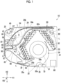
Fig. 1 is a sectional view of an indoor unit of an air conditioner according to an embodiment of the present disclosure. -
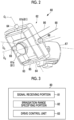
Fig. 2 is a view for describing a configuration of an irradiation part according to the embodiment of the present disclosure. -
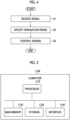
Fig. 3 is a functional block diagram illustrating a configuration of a control device according to the embodiment of the present disclosure. -
Fig. 4 is a functional block diagram illustrating an operation of the control device according to the embodiment of the present disclosure. -
Fig. 5 is a hardware configuration diagram illustrating a configuration of a computer according to the embodiment of the present disclosure. - An air conditioner 1 includes an
indoor unit 10 provided indoors and an outdoor unit (not illustrated) provided outdoors for theindoor unit 10 via a pipe. Theindoor unit 10 suctions indoor air, adjusts a temperature or humidity of the air inside theindoor unit 10, and thereafter, blows out the air to perform air conditioning on the indoor air. - Hereinafter, the
indoor unit 10 according to an embodiment of the present disclosure will be described with reference toFig. 1 . - The
indoor unit 10 includes acasing 20, amain body part 30, anirradiation part 60, asensor 70, and acontrol device 80. - As panels surrounding the
main body part 30 of theindoor unit 10, thecasing 20 has aninlet panel 23, atop surface panel 24, abottom surface panel 22, arear surface panel 21, and a pair of side surface panels (not illustrated). - The
inlet panel 23 is a panel having anintake port 25 in an upper portion to suction air outside thecasing 20 into thecasing 20 and disposed to cover a front surface of themain body part 30. - The
rear surface panel 21 is a panel fixed to an indoor wall for installing theindoor unit 10 and disposed to cover a rear surface of themain body part 30 at a position facing theinlet panel 23. - The
top surface panel 24 is a panel disposed so that end portions of thetop surface panel 24 respectively engage with upper ends of theinlet panel 23 and therear surface panel 21 to cover an upper surface of themain body part 30. - The
bottom surface panel 22 is a panel having anoutlet 26 for blowing the air inside thecasing 20 to the outside of thecasing 20, and disposed to cover a bottom surface of themain body part 30 at a position facing thetop surface panel 24. - The side surface panel is a panel disposed so that end portions of the side surface panel respectively engage with end portions of all of the above-described panels in a width direction H3 to cover right and left side portions of the
main body part 30 in the width direction H3. - Therefore, the
casing 20 formed by the above-described panels has theintake port 25 and theoutlet 26. - Hereinafter, in the present embodiment, an installation direction H1 means a rightward-leftward direction in
Fig. 1 . One side in the installation direction H1 means a direction from therear surface panel 21 toward theinlet panel 23, and the other side in the installation direction H1 means a direction opposite thereto. In addition, an upward-downward direction H2 means an upward-downward direction inFig. 1 , and the width direction H3 means a paper surface depth direction inFig. 1 . - The
main body part 30 has afan 31, aheat exchanger 32, adrain pan 33, a firstaccommodating portion 34a, a second accommodating portion 34b, anair filter 34, a transport roller 36, a removingportion 40, and aflap 35. All of these are provided inside thecasing 20. - The
fan 31 is a so-called cross-flow fan extending in the width direction H3 of thecasing 20. Thefan 31 rotates inside thecasing 20 to circulate air in order of theintake port 25, theheat exchanger 32, and theoutlet 26. - The
heat exchanger 32 is provided to surround an upper-half portion of thefan 31 from an outer periphery thereof. Theheat exchanger 32 has a first heat exchanger and a second heat exchanger. - The first heat exchanger is provided on one side in the installation direction H1 with respect to the
fan 31. When viewed in the width direction H3, the first heat exchanger is bent in the vicinity of the center, and is in a V-shaped state in a direction toward therear surface panel 21 in the installation direction H1. The first heat exchanger is divided into an upper portion and a lower portion around a bent portion. - The second heat exchanger is provided on the other side in the installation direction H1 with respect to the
fan 31. - Upper ends of the first heat exchanger and the second heat exchanger are connected by a
bracket 32a. The first heat exchanger and the second heat exchanger include three panel-shaped heat exchangers 32, and the respective panel is disposed to overlap each other in a direction toward thefan 31. - The air after heat exchange with the
heat exchanger 32 is blown outward of thecasing 20 through theoutlet 26. - The
drain pan 33 is provided below theheat exchanger 32, and extends in the width direction H3. Thedrain pan 33 has a function of a saucer that collects drain water or slime generated from theheat exchanger 32 and receives the drain water or the slime not to leak outward of thecasing 20. The drain water or the slime collected in thedrain pan 33 is discharged outdoor by a drain pipe (not illustrated) connected to thedrain pan 33. - The first
accommodating portion 34a is an accommodating portion that accommodates theair filter 34 provided above the inside of thecasing 20. A portion of the firstaccommodating portion 34a is located among theinlet panel 23, thetop surface panel 24, and the first heat exchanger, and the remaining portion is located between thetop surface panel 24 and the second heat exchanger. Therefore, the firstaccommodating portion 34a extends in the installation direction H1, and the portion of the firstaccommodating portion 34a extends while being curved downward in the upward-downward direction H2 as the firstaccommodating portion 34a is directed to one side from the other side in the installation direction H1. Furthermore, one end of a tip extending downward is close to the transport roller 36, and is open upward of the transport roller 36. - In a state where the
air filter 34 is accommodated, the firstaccommodating portion 34a satisfactorily circulates the air from one side to the other side in the installation direction H1 via theair filter 34, and guides the air to the first heat exchanger and the second heat exchanger. - The second accommodating portion 34b is an accommodating portion of the
air filter 34 provided inside thecasing 20. The second accommodating portion 34b is located among the firstaccommodating portion 34a, the first heat exchanger, and the second heat exchanger. Therefore, the second accommodating portion 34b extends in the installation direction H1, and the second accommodating portion 34b extends while being curved downward in the upward-downward direction H2 as the second accommodating portion 34b is directed to one side from the other side in the installation direction H1. One end of a tip extending downward is close to the transport roller 36, and is open downward of the transport roller 36. - A volume of a space for accommodating the
air filter 34 inside the second accommodating portion 34b is substantially the same as a volume of a space for accommodating theair filter 34 inside the firstaccommodating portion 34a. - In a state where the
air filter 34 is accommodated, the second accommodating portion 34b satisfactorily circulates the air from one side to the other side in the installation direction H1 via theair filter 34, and guides the air to the first heat exchanger and the second heat exchanger. - The
air filter 34 is a sheet-shaped filter accommodated in the firstaccommodating portion 34a and the second accommodating portion 34b. Theair filter 34 has a size precisely fitted to a space that accommodates theair filter 34 of the firstaccommodating portion 34a or a space that accommodates theair filter 34 of the second accommodating portion 34b. Theair filter 34 is accommodated in the firstaccommodating portion 34a as an initial position when theindoor unit 10 starts to be operated. - In a state of being accommodated in the first
accommodating portion 34a, each of theair filters 34 has a plurality of filter gears in end portions in the width direction H3 of a surface of theair filter 34 facing the first heat exchanger side. More specifically, when theair filter 34 is viewed from one side in the installation direction H1, the plurality of filter gears are provided at an equal interval along the installation direction H1 in the end portions of theair filter 34 in the width direction H3. - The transport roller 36 has a columnar shaft extending in the width direction H3 of the
casing 20 and rotating around an axis A extending in the width direction H3, and roller gears. A plurality of the roller gears are provided at an equal interval over a circumferential direction on an outer peripheral surface of an end portion of the shaft in the width direction H3. The roller gear is formed to precisely mesh with the filter gear of theair filter 34. When the shaft portion rotates counterclockwise around the axis A at a predetermined timing in a state where the roller gear and the filter gear mesh with each other, theair filter 34 is guided from the firstaccommodating portion 34a along the outer peripheral surface of the transport roller 36, and is transported into the second accommodating portion 34b. - In addition, when the shaft portion rotates clockwise around the axis A at a predetermined timing after being accommodated inside the second accommodating portion 34b, the
air filter 34 is guided from the second accommodating portion 34b along the outer peripheral surface of the transport roller 36, is transported into the firstaccommodating portion 34a, and returns to an original initial position. - The removing
portion 40 has a columnar shaft portion extending in the width direction H3 of thecasing 20 and rotating around a removing portion axis B extending in the width direction H3, and a brush. - The brush is provided over the circumferential direction to cover the outer peripheral surface of the shaft portion. The brush is formed of a soft material, and has a function of removing fine dust or dirt. A portion of the outer peripheral surface of the brush is in contact with the outer peripheral surface of the transport roller 36 in the width direction H3. When the transport roller 36 rotates, as the
air filter 34 is transported, theair filter 34 is pinched between the transport roller 36 and the brush, and the brush comes into contact with one side surface of theair filter 34 where the roller gear is not provided. - Fine dust or dirt adhering to an entire area of the
air filter 34 is removed by rotation of the brush and friction between the brush and theair filter 34 which occur while one side surface of theair filter 34 comes into contact with the brush. The removed fine dust or dirt falls into adust box 50 existing below the removingportion 40. - The
dust box 50 has a function of a saucer that receives dust or dirt removed from a main body surface of theair filter 34 by the removingportion 40. - The
flap 35 has apanel portion 35a and an adjustingportion 35b. In the present embodiment, themain body part 30 has twoflaps 35. - The
panel portion 35a of eachflap 35 is provided adjacent to theoutlet 26 of thebottom surface panel 22 in the width direction H3. The adjustingportion 35b of eachflap 35 adjusts a blowing direction of the air by adjusting an inclination angle of thepanel portion 35a with respect to a lower surface of thebottom surface panel 22. In addition, when an operation of theindoor unit 10 is stopped, the adjustingportion 35b is driven to bring thepanel portion 35a into a state of being substantially parallel to thebottom surface panel 22. In this manner, theoutlet 26 is brought into a closed state by the twopanel portions 35a. - Hereinafter, the
irradiation part 60 of the present embodiment will be described with reference toFigs. 1 and2 . - The
irradiation part 60 is provided in a space S inside thecasing 20. In the present embodiment, fourirradiation parts 60 are respectively provided inside four spaces S. - The
irradiation part 60 has alight source 61 and adrive part 62. - The
light source 61 includes a light source body 61a and a lightsource support portion 61b. - The light
source support portion 61b is a plateshaped member that supports the light source body 61a. - The light source body 61a is provided in the center of the light
source support portion 61b. The light source body 61a is an LED light bulb capable of projecting directional light L by supplied electric power. The light L is an ultraviolet ray having a sterilizing action by irradiating a bacterium or a virus with the light L. For example, the light L projected from the light source body 61a includes UV-C light. In addition, the reason why the light L which can be projected by the light source body 61a is directional is to secure the amount of energy required for sterilization per unit area of an irradiation range of the light L. - The
drive part 62 includes afirst frame body 63, a first framebody rotating portion 64, asecond frame body 65, a second framebody rotating portion 66, and asupport portion 67. - The
first frame body 63 is a frame-shaped member having a predetermined plate thickness, which is substantially square in a front view and has rounded corners. The lightsource support portion 61b is provided over center portions of a portion corresponding to a pair of facing sides of thefirst frame body 63. In the center of the portion corresponding to the remaining pair of facing sides of thefirst frame body 63 where the lightsource support portion 61b is not provided, the first framebody rotating portion 64, which is a columnar member, is provided to protrude outward. - The
second frame body 65 is a frame-shaped member having a predetermined plate thickness, which is substantially square in a front view and has rounded corners. Thesecond frame body 65 has a shape similar to that of thefirst frame body 63, and has a size in which thefirst frame body 63 is fitted into a frame of thesecond frame body 65. In thesecond frame body 65, a hole having a diameter through which the first framebody rotating portion 64 can penetrate is formed in the center of the portion corresponding to the pair of facing sides. The first framebody rotating portion 64 protruding outward of thefirst frame body 63 passes through the hole, and is rotatably held by thesecond frame body 65 in a state of protruding outward of thesecond frame body 65. - The second frame
body rotating portions 66, each of which is a columnar member, are provided to protrude outward in the center of the portion corresponding to the remaining pair of facing sides on which the hole is not formed in thesecond frame body 65. Furthermore, abracket 90 serving as a support member for the second framebody rotating portion 66 is provided in the space S inside thecasing 20, and the second framebody rotating portion 66 is rotatably supported by thebracket 90. - The pair of first frame
body rotating portions 64 can rotate around a lateral drive axis 01 while the lateral drive axis O1 is used as a common center axis. In this manner, thefirst frame body 63, the lightsource support portion 61b, and the light source body 61a, which are integrated with the first framebody rotating portion 64, can be rotated around the lateral drive axis O1 inside thesecond frame body 65. - In addition, the pair of second frame
body rotating portions 66 can rotate around a longitudinal drive axis O2 while the longitudinal drive axis O2 is used as a common center axis. In this manner, the first framebody rotating portion 64, thefirst frame body 63, the lightsource support portion 61b, and the light source body 61a, which are integrated with the second framebody rotating portion 66, can be rotated around the longitudinal drive axis O2. - Therefore, the
drive part 62 rotatably holds thelight source 61 around two drive axes of the lateral drive axis O1 and the longitudinal drive axis O2. - The
support portion 67 is a member for supporting, driving, and controlling thelight source 61, thefirst frame body 63, the first framebody rotating portion 64, thesecond frame body 65, and the second framebody rotating portion 66, and is provided at an appropriate place inside the four spaces S. Thesupport portion 67 has a built-in servo motor (not illustrated), and is rotatably provided by using power of the servo motor. Thesupport portion 67 has a substantially cylindrical shape, and a tip of thesupport portion 67 on thelight source 61 side is formed to be cut off by a virtual plane inclined with respect to a rotational axis O3 of the servo motor. That is, the tip of thesupport portion 67 is formed along the virtual plane inclined with respect to the rotational axis O3 of the servo motor. Thesupport portion 67 has a wire (not illustrated) for supplying operating electric power to thelight source 61 and the servo motor inside thesupport portion 67, and a control unit for driving and controlling the servo motor. - One surface of the light
source support portion 61b on thesupport portion 67 side is in contact with the tip of thesupport portion 67 on thelight source 61 side. More specifically, the lightsource support portion 61b is provided so that the surface extends along the virtual plane of the tip. In this manner, the lightsource support portion 61b is provided to be inclined with respect to the rotational axis O3 of the servo motor built in thesupport portion 67. - An optical axis of the light source body 61a is provided to be inclined with respect to the rotational axis O3 of the servo motor built in the
support portion 67. An optical axis direction of the light source body 61a coincides with a normal direction of the virtual plane. - When the servo motor is driven, the
support portion 67 rotates around the rotational axis O3. Along with this rotation, the virtual plane three-dimensionally tilts so that the lightsource support portion 61b also performs three-dimensional tilting in accordance with the rotation of thesupport portion 67. Here, thesecond frame body 65 is rotatably held with theindoor unit 10 via the second framebody rotating portion 66. Therefore, the above-describedfirst frame body 63 is further interposed. In this manner, the rotation of the lightsource support portion 61b is restricted while the three-dimensional tilting is allowed. - Driving the servo motor is controlled by a control unit provided inside the
support portion 67. More specifically, in order to keep the servo motor built in thesupport portion 67 at any desired position around the rotational axis O3 of the servo motor, the control unit rotates the servo motor by a predetermined amount at a predetermined timing, and thereafter, stops the servo motor. In addition, a cable that supplies electric power for driving and controlling the servo motor is electrically connected via a control unit inside thesupport portion 67. - That is, the
drive part 62 can be provided at any desired location inside the space S, and the servo motor having the built-insupport portion 67 is rotated. In this manner, the light source body 61a in which the optical axis is tilted with respect to the rotational axis O3 of the servo motor is configured to rotate. Therefore, a wide range inside theindoor unit 10 can be irradiated with the light L by a simple mechanism. - In addition, as the servo motor rotates, the
light source 61 held by thedrive part 62 rotates around two drive axes of the lateral drive axis O1 and the longitudinal drive axis O2. In this manner, it is possible to enlarge an irradiation range of the light L projected by the light source body 61a provided in the lightsource support portion 61b. - In addition, the
irradiation part 60 and thesupport portion 67 have the above-described configuration when theirradiation part 60 is mounted inside theindoor unit 10. Therefore, it is possible to minimize restrictions when theirradiation part 60 and thesupport portion 67 are installed. That is, the irradiation part can three-dimensionally tilt around the two drive axes by using one servo motor. Therefore, cable wiring can be easily arranged, and it is possible to minimize a volume ratio occupied by theirradiation part 60 inside the space S. In this manner, when it becomes necessary to mount a plurality of the irradiation parts in accordance with locations requiring sterilization inside theindoor unit 10, it is possible to particularly effectively secure mounting ability of theirradiation part 60 on theindoor unit 10. - The
first irradiation part 60 in the present embodiment is provided inside the space S partitioned into the second heat exchanger, therear surface panel 21, and thetop surface panel 24. More specifically, thesupport portion 67 is fixed to a surface of therear surface panel 21 facing the inside of thecasing 20, and thelight source 61 is disposed to face the whole second heat exchanger and thedrain pan 33 below the second heat exchanger. In this manner, since thedrive part 62 is rotationally driven, the whole second heat exchanger and thedrain pan 33 below the second heat exchanger can be irradiated with the light L. - In addition, the
light source 61 can face theoutlet 26 and theflap 35 by rotating thedrive part 62. In this manner, theoutlet 26 and theflap 35 can be irradiated with the light L from the inside of thecasing 20 via the second heat exchanger, thedrain pan 33, and thefan 31. - The
second irradiation part 60 in the present embodiment is provided inside the space S partitioned into the firstaccommodating portion 34a, thetop surface panel 24, and theinlet panel 23. More specifically, thesupport portion 67 is fixed to a surface of thetop surface panel 24 facing the inside of thecasing 20, and thelight source 61 is disposed to face the firstaccommodating portion 34a and theair filter 34. In this manner, since thedrive part 62 is rotationally driven, theair filter 34 can be irradiated with the light L. - In addition, the
drive part 62 is rotated so that thelight source 61 can face theintake port 25. In this manner, theintake port 25 can be irradiated with the light L from the inside of thecasing 20. - The
third irradiation part 60 in the present embodiment is provided inside the space S partitioned into the firstaccommodating portion 34a and the second accommodating portion 34b. More specifically, thesupport portion 67 is fixed to a surface of the firstaccommodating portion 34a facing the first heat exchanger, and thelight source 61 is disposed to face an entire upper portion of the second accommodating portion 34b and the first heat exchanger. In this manner, since thedrive part 62 is rotationally driven, the entire upper portion of the first heat exchanger can be irradiated with the light L. - In addition, when the
air filter 34 is accommodated in the second accommodating portion 34b, a surface provided with the filter gear portion in theair filter 34 can be irradiated with the light L. - The
fourth irradiation part 60 in the present embodiment is provided inside the space S partitioned into thedust box 50, the second accommodating portion 34b, the first heat exchanger, and thebottom surface panel 22. More specifically, thesupport portion 67 is fixed to a portion of thedust box 50 facing the first heat exchanger, and thelight source 61 is disposed to face the entire lower portion of the first heat exchanger and thedrain pan 33 below the first heat exchanger. In this manner, since thedrive part 62 is rotationally driven, the entire lower portion of the first heat exchanger and thedrain pan 33 below the first heat exchanger can be irradiated with the light L. - In addition, since the
drive part 62 rotates, thelight source 61 can face theoutlet 26. In this manner, theoutlet 26 can be irradiated with the light L from the inside of thecasing 20 via the first heat exchanger and thedrain pan 33 below the first heat exchanger. - Therefore, the
irradiation part 60 is provided inside thecasing 20 so that at least one of theintake port 25, theheat exchanger 32, and theoutlet 26 can be irradiated with the light L projected from thelight source 61. - The
sensor 70 is provided in the vicinity of theflap 35 on the bottom surface of theindoor unit 10. - For example, the
sensor 70 is a pyroelectric sensor that can detect that a person is present around theindoor unit 10, or a solar radiation sensor that detects brightness in a room in which theindoor unit 10 is installed. - When the
sensor 70 is the pyroelectric sensor, the pyroelectric sensor transmits a person detection signal to thecontrol device 80 after detecting that the person is present in the room. - When the
sensor 70 is the solar radiation sensor, and when detecting that illuminance in the room is lower (darker) than a predetermined illuminance threshold value, the solar radiation sensor transmits an illuminance detection signal to thecontrol device 80. - The
control device 80 is provided in the vicinity of a wall surface of a main body lower portion of theindoor unit 10. Thecontrol device 80 receives a detection signal transmitted from thesensor 70, specifies an irradiation range of the light L emitted by theirradiation part 60, transmits a drive control signal to the control unit inside thesupport portion 67, and controls driving of thedrive part 62. - The
control device 80 includes asignal receiving portion 81, an irradiationrange specifying portion 82, and adrive control unit 83. Thecontrol device 80 is connected to thesensor 70 by wire or wirelessly. - The
signal receiving portion 81 receives the detection signal transmitted from thesensor 70. Thesignal receiving portion 81 transmits the received detection signal to the irradiationrange specifying portion 82. - The irradiation
range specifying portion 82 specifies the irradiation range of the light L of theirradiation part 60, based on detection data included in the received detection signal. - The irradiation range specified by the irradiation
range specifying portion 82 includes a first irradiation range and a second irradiation range. The first irradiation range is a range in which theirradiation part 60 irradiates a wide range inside thecasing 20 with the light L. The second irradiation range is an irradiation range of the light L which is narrower than the first irradiation range, and is a range in which the light L projected by theirradiation part 60 does not leak outward of theindoor unit 10. - When the detection data received by the irradiation
range specifying portion 82 is person detection data transmitted from a person detection sensor, the irradiationrange specifying portion 82 specifies the irradiation range as a second irradiation range. - When the detection data received by the irradiation
range specifying portion 82 is illuminance data transmitted from an illuminance sensor, the irradiationrange specifying portion 82 compares a value of the illuminance data with a predetermined threshold value, and when the value of the illuminance data is lower than the threshold value, the irradiationrange specifying portion 82 determines that the room is dark, and specifies the irradiation range as a second irradiation range. In addition, the irradiationrange specifying portion 82 compares the value of the illuminance data with the predetermined threshold value, and when the value of the illuminance data is higher than the threshold value, the irradiationrange specifying portion 82 determines that the room is bright, and specifies the irradiation range as the first irradiation range. - After the irradiation
range specifying portion 82 specifies the irradiation range, thedrive control unit 83 transmits a control signal based on the specified irradiation range to the control unit inside thesupport portion 67. - When the irradiation
range specifying portion 82 specifies the irradiation range as the first irradiation range, thedrive control unit 83 transmits a signal for normal-time driving to the control units inside all of thesupport portions 67 provided inside thecasing 20. In addition, when the irradiationrange specifying portion 82 specifies the irradiation range as the second irradiation range, thedrive control unit 83 transmits a signal for bringing theirradiation part 60 into a state of facing thetop surface panel 24 side to the control units inside all of thesupport portions 67 provided inside thecasing 20. - Hereinafter, an operation of the
control device 80 will be described.Fig. 4 is a flowchart illustrating the operation of thecontrol device 80. - The
signal receiving portion 81 receives the detection data transmitted from the sensor 70 (Step S1). - The irradiation
range specifying portion 82 specifies the irradiation range of the light L of theirradiation part 60, based on the detection data received by the signal receiving portion 81 (Step S2). - The
drive control unit 83 transmits a signal for instructing the driving to the control unit inside thesupport portion 67, based on the irradiation range specified by the irradiationrange specifying portion 82, and controls the driving of the drive part 62 (Step S3). - According to the above-described configuration, the
drive part 62 can change a posture of thelight source 61. In this manner, the posture of thelight source 61 that projects the light L having a sterilizing action can be changed by thedrive part 62. Therefore, a wide range inside thecasing 20 can be irradiated with the light L, and bacteria or viruses can be sterilized. - In addition, the
irradiation part 60 rotates around the lateral drive axis O1 and the longitudinal drive axis O2. In this manner, since thedrive part 62 rotates around the two axes, the posture of thelight source 61 can be changed by the two axes. Therefore, a direction in which the light L is projected by thelight source 61 can be three-dimensionally changed in any desired way. Therefore, a wide range can be irradiated with the light L. - In addition, the servo motor built in the
support portion 67 can be kept at a predetermined position at any desired timing. That is, the control unit controls the postures of the plurality ofirradiation parts 60 so that the same location can be intensively irradiated with the light L projected by the plurality ofirradiation parts 60. Accordingly, partial sterilizing ability can be improved. In this manner, even when bacteria or viruses locally appear inside theindoor unit 10, bacteria or viruses can be effectively sterilized. - In addition, the
irradiation part 60 is provided so that theintake port 25, theheat exchanger 32, and theoutlet 26 are irradiated with the light L projected from thelight source 61. In this manner, bacteria or viruses contained in the air introduced into thecasing 20, or in the air blown out of theheat exchanger 32 and thecasing 20 can be sterilized. Therefore, clean air can be provided indoors. - In addition, the
irradiation part 60 is provided so that thedrain pan 33 can be irradiated with the light L projected from thelight source 61. In this manner, thedrain pan 33 in which bacteria or viruses are likely to appear can be sterilized, and the inside of thecasing 20 can be kept in a cleaner state with less bacteria and viruses. Therefore, cleaner air can be provided indoors. - In addition, the
irradiation part 60 is provided so that theair filter 34 can be irradiated with the light L projected from thelight source 61. In this manner, the inside of thecasing 20 can be kept in a cleaner state with less bacteria and viruses. Therefore, cleaner air can be provided indoors. - In addition, since bacteria or viruses adhering to the
air filter 34 are sterilized, even during maintenance such as cleaning theair filter 34, when a user of theindoor unit 10 accidentally suctions fine dust or dirt, an adverse effect on a human body is reduced. - In addition, the transport roller 36 rotates so that the
air filter 34 is transported from the first accommodating portion to the second accommodating portion or from the second accommodating portion to the first accommodating portion. In this manner, a location which is not irradiated with the light L before theair filter 34 is transported due to intermediate transport stopping can be irradiated with the light L. Therefore, theair filter 34 can be evenly irradiated with the light L. - In addition, the
control device 80 drives and controls thedrive part 62, based on the detection signal of thesensor 70. In this manner, when a person is present in the vicinity of theindoor unit 10 or when the room is dark while a user of theindoor unit 10 sleeps, the light L of theirradiation part 60 does not leak outward of thecasing 20. Therefore, theindoor unit 10 can be safely used. - In addition, the light L that can be projected by the light source body 61a is directional, and the control unit can rotate the
light source 61. In this manner, the irradiation range of the light L can be continuously enlarged while the amount of energy required for sterilization per unit area of the irradiation range of the light L is secured. Therefore, effective sterilization inside theindoor unit 10 can be realized. - Hitherto, the embodiments of the present disclosure have been described in detail with reference to the drawings. However, specific configurations are not limited to the configurations of each embodiment, and additions, omissions, and substitutions of configurations and other modifications can be made within the scope not departing from the concept of the present disclosure. In addition, the present disclosure is not limited by the embodiments, and is limited only by the appended claims.
-
Fig. 5 is a hardware configuration diagram illustrating a configuration of acomputer 1100 according to the above-described embodiment. - A
computer 1100 includes aprocessor 1110, amain memory 1120, astorage 1130, and aninterface 1140. - The above-described
control device 80 is mounted on thecomputer 1100. Then, the operation of each of the processing units described above is stored in thestorage 1130 in a form of a program. Theprocessor 1110 reads the program from thestorage 1130, develops the read program in themain memory 1120, and executes the above-described process in accordance with the program. In addition, theprocessor 1110 secures a storage area corresponding to each storage unit described above in themain memory 1120 in accordance with the program. - The program may be intended to realize some of functions fulfilled by the
computer 1100. For example, the program may fulfill a function in combination with another program previously stored in thestorage 1130, or in combination with another program installed in another device. In addition, thecomputer 1100 may include a custom large scale integrated circuit (LSI) such as a programmable logic device (PLD) in addition to or in place of the above-described configuration. Examples of the PLD include a programmable array logic (PAL), a generic array logic (GAL), a complex programmable logic device (CPLD), and a field programmable gate array (FPGA). In this case, functions that are realized by theprocessor 1110 may be partially or entirely realized by the integrated circuit. - As an example of the
storage 1130, a magnetic disk, a magneto-optical disk, or a semiconductor memory can be used. Thestorage 1130 may be an internal medium directly connected to a bus of thecomputer 1100, or may be an external medium connected to thecomputer 1100 via theinterface 1140 or a communication line. In addition, when this program is distributed to thecomputer 1100 via the communication line, thecomputer 1100 receiving the distributed program may develop the program in themain memory 1120 to execute the above-described process. In the above-described embodiment, thestorage 1130 is a tangible storage medium that is not temporary. - In addition, the program may be used to partially realize the above-described functions. In addition, the program may be a so-called difference file (difference program) that realizes the above-described functions in combination with another program previously stored in the
storage 1130. - In addition, in the above-described embodiment, an example in which every
irradiation part 60 is provided in each of the four spaces S inside thecasing 20 has been described. However, the number of theirradiation parts 60 is not limited, and a plurality of theirradiation parts 60 may be provided inside the space S. In this manner, the postures of the plurality ofirradiation parts 60 are separately controlled so that the inside of theindoor unit 10 can be more efficiently sterilized. - In addition, in the above-described embodiment, the
irradiation part 60 is provided to be rotatable around the two axes by the rotation of the first frame body rotating portion and the second frame body rotating portion. However, the rotational axes of theirradiation part 60 are not limited to the two axes, and a configuration of the rotation around three or more axes may be adopted. - In addition, in the above-described embodiment, the
irradiation part 60 is configured to directly irradiate each member, but may be configured to indirectly irradiate the member by using a light guide plate to reflect the light L. In this manner, a blind spot portion or a narrow portion of the member can be irradiated with the light L, and a wider range can be irradiated with the light L. - In addition, in the above-described embodiment, the
sensor 70 is provided in the vicinity of theflap 35 on the bottom surface of theindoor unit 10, and thecontrol device 80 is provided in the vicinity of the lower portion of therear surface panel 21. However, a place for providing thesensor 70 and thecontrol device 80 is not limited. Thesensor 70 and thecontrol device 80 may be provided at an appropriate place inside or outside the casing. - In addition, the
sensor 70 may be an infrared sensor. A configuration in which a person detection signal is transmitted to thecontrol device 80 may be adopted, when the infrared sensor detects that a person is present by using temperature information in the vicinity of theindoor unit 10 which is obtained from the infrared sensor. - In addition, a member such as a rail extending in the width direction H3 may be provided inside the space S, and the
support portion 67 for supporting theirradiation part 60 may be provided on the rail. In this manner, a configuration may be adopted so that theirradiation part 60 can move in the width direction H3. In this manner, a wider range can be more effectively irradiated with the light L. - In addition, the
signal receiving portion 81 may receive an input of information related to specifying the irradiation range by using a remote controller (not illustrated) of theindoor unit 10. - In addition, an operation for setting a timer may be performed on the
control device 80 by using the remote controller of theindoor unit 10, and the irradiationrange specifying portion 82 may specify the irradiation range at a time of the set timer. - For example, the air conditioner 1 according to the above-described embodiment is understood as follows.
-
- (1) According to a first aspect, there is provided the air conditioner 1 including the
casing 20 having theintake port 25 and theoutlet 26, theheat exchanger 32 provided inside thecasing 20, thefan 31 provided inside thecasing 20 to circulate the air in order of theintake port 25, theheat exchanger 32, and theoutlet 26; and theirradiation part 60 provided inside thecasing 20. Theirradiation part 60 has thelight source 61 that projects the directional ultraviolet rays, and thedrive part 62 that drives thelight source 61 to change a posture of thelight source 61.
In this manner, the posture of thelight source 61 that projects the light L having a sterilizing action can be changed by thedrive part 62. Therefore, a wide range inside thecasing 20 can be irradiated with the light L. - (2) According to a second aspect of the air conditioner 1, in the air conditioner 1 of (1), the
drive part 62 may drive theirradiation part 60 to rotate around at least two drive axes.
In this manner, a direction in which the light L is projected by thelight source 61 can be three-dimensionally changed. Therefore, a wide range can be irradiated with the light L. - (3) According to a third aspect of the air conditioner 1, in the air conditioner 1 of (1) or (2), the
irradiation part 60 may be provided so that at least one of theintake port 25, theheat exchanger 32, and theoutlet 26 is irradiated with the ultraviolet rays projected from thelight source 61.
In this manner, bacteria or viruses contained in the air introduced into thecasing 20, or in the air blown out of theheat exchanger 32 and thecasing 20 can be sterilized. - (4) According to a fourth aspect of the air conditioner 1, the air conditioner 1 of any one of (1) to (3) may further include the
drain pan 33 below theheat exchanger 32 inside thecasing 20. Theirradiation part 60 may be provided so that thedrain pan 33 is irradiated with the ultraviolet rays projected from thelight source 61.
In this manner, thedrain pan 33 in which bacteria or viruses are likely to appear can be sterilized, and the inside of thecasing 20 can be kept in a cleaner state with less bacteria and viruses. - (5) According to a fifth aspect of the air conditioner 1, the air conditioner 1 of any one of (1) to (4) may further include the
air filter 34 provided between theintake port 25 and theheat exchanger 32 inside thecasing 20. Theirradiation part 60 may be provided so that theair filter 34 is irradiated with the ultraviolet rays projected from thelight source 61.
In this manner, the inside of thecasing 20 can be kept in a cleaner state with less bacteria and viruses. In addition, during maintenance such as cleaning theair filter 34, when a person accidentally suctions fine dust or dirt, an adverse effect on a human body is reduced. - (6) According to a sixth aspect of the air conditioner 1, the air conditioner 1 of (5) may further include the transport roller 36 that transports the
air filter 34 by rotating around the axis extending in the width direction H3 of thecasing 20, and the removingportion 40 that removes a substance adhering to theair filter 34 by coming into contact with theair filter 34 transported by the transport roller 36.
In this manner, theair filter 34 can be evenly irradiated with the light L. - (7) According to a seventh aspect of the air conditioner 1, the air conditioner 1 of any one of (1) to (6) may further include the
control device 80 that adjusts the irradiation range of thelight source 61 by controlling thedrive part 62. In accordance with a signal from the outside, thecontrol device 80 may control thedrive part 62 to set the irradiation range to any one of the first irradiation range and the second irradiation range narrower than the first irradiation range. - In this manner, when a person is present in the vicinity of the
indoor unit 10 or when the room is dark while a user of theindoor unit 10 sleeps, the light L of theirradiation part 60 does not leak outward of thecasing 20, and the user of theindoor unit 10 can safely use theindoor unit 10. - According to the present disclosure, it is possible to provide an air conditioner capable of irradiating a wide range inside an indoor unit with ultraviolet rays.
-
- 1: Air conditioner
- 10: Indoor unit
- 20: Casing
- 21: Rear surface panel
- 22: Bottom surface panel
- 23: Inlet panel
- 24: Top surface panel
- 25: Intake port
- 26: Outlet
- 30: Main body part
- 31: Fan
- 32: Heat exchanger
- 32a: Bracket
- 33: Drain pan
- 34: Air filter
- 34a: First accommodating portion
- 34b: Second accommodating portion
- 35: Flap
- 35a: Panel portion
- 35b: Adjusting portion
- 36: Transport roller
- 40: Removing portion
- 50: Dust box
- 60: Irradiation part
- 61: Light source
- 61a: Light source body
- 61b: Light source support portion
- 62: Drive part
- 63: First frame body
- 64: First frame body rotating portion
- 65: Second frame body
- 66: Second frame body rotating portion
- 67: Support portion
- 70: Sensor
- 80: Control device
- 81: Signal receiving portion
- 82: Irradiation range specifying portion
- 83 Drive control unit
- 90: Bracket
- 1100: Computer
- 1110: Processor
- 1120: Main memory
- 1130: Storage
- 1140: Interface
- A: Axis
- B: Removing portion axis
- H1: Installation direction
- H2: Upward-downward direction
- H3: Width direction
- L: Light
- O1: Lateral drive axis
- O2: Longitudinal drive axis
- O3: Rotational axis
- S: Space
Claims (7)
- An air conditioner comprising:a casing having an intake port and an outlet;a heat exchanger provided inside the casing;a fan provided inside the casing to circulate air in order of the intake port, the heat exchanger, and the outlet; andan irradiation part provided inside the casing,wherein the irradiation part hasa light source that projects directional ultraviolet rays, anda drive part that drives the light source to change a posture of the light source.
- The air conditioner according to Claim 1,
wherein the drive part drives the irradiation part to rotate around at least two drive axes. - The air conditioner according to Claim 1 or 2,
wherein the irradiation part is provided so that at least one of the intake port, the heat exchanger, and the outlet is irradiated with the ultraviolet rays projected from the light source. - The air conditioner according to any one of Claims 1 to 3, further comprising:a drain pan provided below the heat exchanger inside the casing,wherein the irradiation part is provided so that the drain pan is irradiated with the ultraviolet rays projected from the light source.
- The air conditioner according to any one of Claims 1 to 4, further comprising:an air filter provided between the intake port and the heat exchanger inside the casing,wherein the irradiation part is provided so that the air filter is irradiated with the ultraviolet rays projected from the light source.
- The air conditioner according to Claim 5, further comprising:a transport roller that transports the air filter by rotating around an axis extending in a width direction of the casing; anda removing portion that removes a substance adhering to the air filter by coming into contact with the air filter transported by the transport roller.
- The air conditioner according to any one of Claims 1 to 6, further comprising:a control device that adjusts an irradiation range of the light source by controlling the drive part,wherein in accordance with a signal from an outside, the control device controls the drive part to set the irradiation range to any one of a first irradiation range and a second irradiation range narrower than the first irradiation range.
Applications Claiming Priority (2)
| Application Number | Priority Date | Filing Date | Title |
|---|---|---|---|
| JP2021027835A JP7770104B2 (en) | 2021-02-24 | 2021-02-24 | air conditioner |
| PCT/JP2021/039702 WO2022180932A1 (en) | 2021-02-24 | 2021-10-27 | Air conditioner |
Publications (2)
| Publication Number | Publication Date |
|---|---|
| EP4283202A1 true EP4283202A1 (en) | 2023-11-29 |
| EP4283202A4 EP4283202A4 (en) | 2024-06-12 |
Family
ID=83047962
Family Applications (1)
| Application Number | Title | Priority Date | Filing Date |
|---|---|---|---|
| EP21928027.8A Pending EP4283202A4 (en) | 2021-02-24 | 2021-10-27 | Air conditioner |
Country Status (4)
| Country | Link |
|---|---|
| EP (1) | EP4283202A4 (en) |
| JP (1) | JP7770104B2 (en) |
| AU (1) | AU2021430178B2 (en) |
| WO (1) | WO2022180932A1 (en) |
Family Cites Families (12)
| Publication number | Priority date | Publication date | Assignee | Title |
|---|---|---|---|---|
| JPH0464014U (en) * | 1990-10-15 | 1992-06-01 | ||
| US5755103A (en) * | 1995-09-16 | 1998-05-26 | Samsung Electronics Co., Ltd. | Room air conditioner with sterilizing apparatus |
| JP2002177372A (en) * | 2000-12-19 | 2002-06-25 | Sanyo Electric Co Ltd | Photocatalyst filter apparatus |
| JP3852429B2 (en) * | 2003-08-06 | 2006-11-29 | 株式会社日立製作所 | Air cleaner |
| JP4736749B2 (en) * | 2005-11-25 | 2011-07-27 | 株式会社富士通ゼネラル | Ultraviolet irradiation device and air conditioner equipped with the same ultraviolet irradiation device |
| JP2007162976A (en) * | 2005-12-12 | 2007-06-28 | Fujitsu General Ltd | Drive device and air conditioner equipped with the drive device |
| JP2009014259A (en) | 2007-07-04 | 2009-01-22 | Mitsubishi Electric Corp | Air conditioner |
| ES2681602T3 (en) | 2013-03-07 | 2018-09-14 | Viacyte, Inc. | Large capacity three-dimensional cellular encapsulation device assembly |
| JP5799263B1 (en) | 2014-03-31 | 2015-10-21 | パナソニックIpマネジメント株式会社 | Air conditioner |
| JP2016200290A (en) | 2015-04-07 | 2016-12-01 | ジョンソンコントロールズ ヒタチ エア コンディショニング テクノロジー(ホンコン)リミテッド | Air conditioner |
| JP6283014B2 (en) * | 2015-12-14 | 2018-02-21 | 株式会社トクヤマ | Air conditioner for automobile |
| JP6668296B2 (en) | 2017-07-31 | 2020-03-18 | 矢崎総業株式会社 | Vehicle lighting system |
-
2021
- 2021-02-24 JP JP2021027835A patent/JP7770104B2/en active Active
- 2021-10-27 EP EP21928027.8A patent/EP4283202A4/en active Pending
- 2021-10-27 WO PCT/JP2021/039702 patent/WO2022180932A1/en not_active Ceased
- 2021-10-27 AU AU2021430178A patent/AU2021430178B2/en active Active
Also Published As
| Publication number | Publication date |
|---|---|
| JP7770104B2 (en) | 2025-11-14 |
| AU2021430178B2 (en) | 2025-05-15 |
| EP4283202A4 (en) | 2024-06-12 |
| JP2022129217A (en) | 2022-09-05 |
| AU2021430178A1 (en) | 2023-09-07 |
| WO2022180932A1 (en) | 2022-09-01 |
Similar Documents
| Publication | Publication Date | Title |
|---|---|---|
| CN107642822B (en) | Air conditioner | |
| JP4574799B2 (en) | UV sterilizer | |
| JP6611006B2 (en) | Recessed ceiling indoor unit | |
| KR20200131115A (en) | Indoor unit of an air conditioner and a method controlling the same | |
| CN114270104B (en) | air conditioner | |
| JP6597891B2 (en) | Air cleaner | |
| AU2010293674A1 (en) | Air conditioner | |
| CN102483254B (en) | Air conditioner | |
| JP6505544B2 (en) | Culture device | |
| KR20180010731A (en) | Air conditioner | |
| CN113631864A (en) | Air conditioner and control method thereof | |
| AU2021430178B2 (en) | Air conditioner | |
| KR20180010762A (en) | Air conditioner | |
| JP2000170466A (en) | Day lighting window | |
| KR20180010768A (en) | Air conditioner | |
| KR20200109016A (en) | Air conditioner | |
| CN107850319A (en) | Indoor unit of air conditioner | |
| ES2966487T3 (en) | Air conditioner | |
| CN214074335U (en) | Sterilizing device with rotatable tray | |
| TWI897054B (en) | Dehumidifier | |
| JP7719757B2 (en) | air conditioning equipment | |
| KR20200113668A (en) | Air conditioner and control method thereof | |
| KR102160067B1 (en) | Louver System Having Blast Unit Installed Blade | |
| CN110195898A (en) | A kind of multi-functional air conditioner | |
| KR100764733B1 (en) | Packaged air conditioner with independent air cleaning |
Legal Events
| Date | Code | Title | Description |
|---|---|---|---|
| STAA | Information on the status of an ep patent application or granted ep patent |
Free format text: STATUS: THE INTERNATIONAL PUBLICATION HAS BEEN MADE |
|
| PUAI | Public reference made under article 153(3) epc to a published international application that has entered the european phase |
Free format text: ORIGINAL CODE: 0009012 |
|
| STAA | Information on the status of an ep patent application or granted ep patent |
Free format text: STATUS: REQUEST FOR EXAMINATION WAS MADE |
|
| 17P | Request for examination filed |
Effective date: 20230822 |
|
| AK | Designated contracting states |
Kind code of ref document: A1 Designated state(s): AL AT BE BG CH CY CZ DE DK EE ES FI FR GB GR HR HU IE IS IT LI LT LU LV MC MK MT NL NO PL PT RO RS SE SI SK SM TR |
|
| DAV | Request for validation of the european patent (deleted) | ||
| DAX | Request for extension of the european patent (deleted) | ||
| A4 | Supplementary search report drawn up and despatched |
Effective date: 20240513 |
|
| RIC1 | Information provided on ipc code assigned before grant |
Ipc: F24F 8/90 20210101ALI20240506BHEP Ipc: F24F 8/22 20210101ALI20240506BHEP Ipc: F24F 1/0071 20190101AFI20240506BHEP |
|
| STAA | Information on the status of an ep patent application or granted ep patent |
Free format text: STATUS: EXAMINATION IS IN PROGRESS |