EP4283169A1 - Electromagnetic valve - Google Patents
Electromagnetic valve Download PDFInfo
- Publication number
- EP4283169A1 EP4283169A1 EP22742468.6A EP22742468A EP4283169A1 EP 4283169 A1 EP4283169 A1 EP 4283169A1 EP 22742468 A EP22742468 A EP 22742468A EP 4283169 A1 EP4283169 A1 EP 4283169A1
- Authority
- EP
- European Patent Office
- Prior art keywords
- component
- electromagnetic valve
- flow path
- solenoid housing
- movable element
- Prior art date
- Legal status (The legal status is an assumption and is not a legal conclusion. Google has not performed a legal analysis and makes no representation as to the accuracy of the status listed.)
- Withdrawn
Links
Images





Classifications
-
- F—MECHANICAL ENGINEERING; LIGHTING; HEATING; WEAPONS; BLASTING
- F16—ENGINEERING ELEMENTS AND UNITS; GENERAL MEASURES FOR PRODUCING AND MAINTAINING EFFECTIVE FUNCTIONING OF MACHINES OR INSTALLATIONS; THERMAL INSULATION IN GENERAL
- F16K—VALVES; TAPS; COCKS; ACTUATING-FLOATS; DEVICES FOR VENTING OR AERATING
- F16K27/00—Construction of housing; Use of materials therefor
- F16K27/02—Construction of housing; Use of materials therefor of lift valves
- F16K27/029—Electromagnetically actuated valves
-
- F—MECHANICAL ENGINEERING; LIGHTING; HEATING; WEAPONS; BLASTING
- F16—ENGINEERING ELEMENTS AND UNITS; GENERAL MEASURES FOR PRODUCING AND MAINTAINING EFFECTIVE FUNCTIONING OF MACHINES OR INSTALLATIONS; THERMAL INSULATION IN GENERAL
- F16K—VALVES; TAPS; COCKS; ACTUATING-FLOATS; DEVICES FOR VENTING OR AERATING
- F16K31/00—Actuating devices; Operating means; Releasing devices
- F16K31/02—Actuating devices; Operating means; Releasing devices electric; magnetic
- F16K31/06—Actuating devices; Operating means; Releasing devices electric; magnetic using a magnet, e.g. diaphragm valves, cutting off by means of a liquid
- F16K31/0603—Multiple-way valves
- F16K31/0624—Lift valves
-
- F—MECHANICAL ENGINEERING; LIGHTING; HEATING; WEAPONS; BLASTING
- F16—ENGINEERING ELEMENTS AND UNITS; GENERAL MEASURES FOR PRODUCING AND MAINTAINING EFFECTIVE FUNCTIONING OF MACHINES OR INSTALLATIONS; THERMAL INSULATION IN GENERAL
- F16K—VALVES; TAPS; COCKS; ACTUATING-FLOATS; DEVICES FOR VENTING OR AERATING
- F16K31/00—Actuating devices; Operating means; Releasing devices
- F16K31/02—Actuating devices; Operating means; Releasing devices electric; magnetic
- F16K31/06—Actuating devices; Operating means; Releasing devices electric; magnetic using a magnet, e.g. diaphragm valves, cutting off by means of a liquid
- F16K31/0644—One-way valve
- F16K31/0655—Lift valves
-
- F—MECHANICAL ENGINEERING; LIGHTING; HEATING; WEAPONS; BLASTING
- F16—ENGINEERING ELEMENTS AND UNITS; GENERAL MEASURES FOR PRODUCING AND MAINTAINING EFFECTIVE FUNCTIONING OF MACHINES OR INSTALLATIONS; THERMAL INSULATION IN GENERAL
- F16K—VALVES; TAPS; COCKS; ACTUATING-FLOATS; DEVICES FOR VENTING OR AERATING
- F16K41/00—Spindle sealings
- F16K41/10—Spindle sealings with diaphragm, e.g. shaped as bellows or tube
-
- F—MECHANICAL ENGINEERING; LIGHTING; HEATING; WEAPONS; BLASTING
- F16—ENGINEERING ELEMENTS AND UNITS; GENERAL MEASURES FOR PRODUCING AND MAINTAINING EFFECTIVE FUNCTIONING OF MACHINES OR INSTALLATIONS; THERMAL INSULATION IN GENERAL
- F16K—VALVES; TAPS; COCKS; ACTUATING-FLOATS; DEVICES FOR VENTING OR AERATING
- F16K41/00—Spindle sealings
- F16K41/10—Spindle sealings with diaphragm, e.g. shaped as bellows or tube
- F16K41/12—Spindle sealings with diaphragm, e.g. shaped as bellows or tube with approximately flat diaphragm
Definitions
- the present invention relates to an electromagnetic valve.
- Patent Literature 1 discloses an electromagnetic valve including a solenoid, a sealing portion provided on a movable element, a first pipe, and a second pipe.
- Patent Literature 1 JP2020-94622A
- one component defines a flow path of a fluid in the electromagnetic valve. For example, it is not easy to change a specification of the electromagnetic valve.
- An object of a first aspect of the present invention is to provide an electromagnetic valve in which strength of a portion supporting a component can be easily ensured and a specification can be easily changed.
- An object of a second aspect of the present invention is to provide an electromagnetic valve of which a specification can be easily changed.
- An object of a third aspect of the present invention is to provide an electromagnetic valve capable of preventing an increase in distance between components.
- An object of a fourth aspect of the present invention is to provide an electromagnetic valve capable of preventing a fluid from flowing to a coil side and capable of operating a movable element with less electric power.
- An object of a fifth aspect of the present invention to provide an electromagnetic valve capable of preventing movement of a movable element from being hindered.
- An electromagnetic valve according to one aspect of the present invention including:
- the connection portion that allows the fluid to flow between the flow path forming portion and the outside can be extended from the first component. Further, compared to a configuration in which the connection portion is sandwiched between a plurality of the first lock portions on a side on which the connection portion is provided, even when the connection portion is enlarged, a width of the first lock portion is easily ensured, and strength is easily ensured. Further, when the space provided from the first lock portion to the second end portion side is sufficiently large, the connection portion can be switched to a small or large connection portion only by replacing the first component without changing a specification of the supporting portion.
- An electromagnetic valve including:
- the electromagnetic valve includes the flow path forming portion including the first component and the second component, and the solenoid housing, and the first component and the second component forms the flow path, and thus by replacing at least one of the first component and the second component, it is possible to easily change a specification such as the number of switchable flow paths while using common portions such as the solenoid and the solenoid housing.
- An electromagnetic valve including:
- the first movement restriction portions and the second movement restriction portions are provided.
- the first movement restriction portions restrict the relative movement of the solenoid housing and the second component in the direction away from each other, and the second movement restriction portions restrict the relative movement of the first component and the second component in the direction away from each other. Therefore, it is possible to prevent the first component from moving relative to the solenoid housing and to prevent an increase in distance between the first component and the second component.
- An electromagnetic valve including:
- the seal portion By providing the seal portion, it is possible to prevent the flow of the fluid from the flow path forming portion to the coil. Further, since the seal portion extends and contracts in accordance with the reciprocation of the movable element, the movable element can be operated with less electric power than, for example, a case of using a structure in which the seal portion does not expand and contract and slides on the movable element.
- An electromagnetic valve including:
- the solenoid housing includes the communication passage that allows the gas to flow between the inside and the outside thereof, and it is possible to prevent movement of the movable element from being hindered by a pressure difference between the inside and outside of the solenoid housing.
- the first aspect of the present invention it is possible to provide an electromagnetic valve in which strength of a portion supporting a component can be easily ensured and a specification can be easily changed.
- an electromagnetic valve capable of preventing an increase in distance between components.
- an electromagnetic valve capable of preventing a fluid from flowing to a coil side and operating a movable element with less electric power.
- an electromagnetic valve capable of preventing movement of a movable element from being hindered.
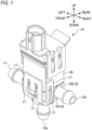
- FIG. 1 is a perspective view of an electromagnetic valve 1A according to a first embodiment.
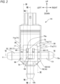
- FIG. 2 is a front view of the electromagnetic valve 1A.
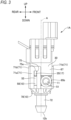
- FIG. 3 is a left side view of the electromagnetic valve 1A.
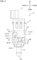
- FIG. 4 is a right side view of the electromagnetic valve 1A.
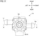
- FIG. 5 is a bottom view of the electromagnetic valve 1A.
- FIG. 6 is a cross-sectional view of the electromagnetic valve 1A taken along an arrow direction of a line VI-VI in FIG. 2 .
- FIG. 7 is a cross-sectional view of the electromagnetic valve 1A in a first state to be described later, which is taken along an arrow direction of a line V-V in FIG. 5 .
- the electromagnetic valve 1A is mounted, for example, on a cleaner that cleans a vehicle lamp which is mounted on a vehicle, an on-vehicle sensor, or a windshield of the vehicle.
- the electromagnetic valve 1A is mounted on a cleaner that cleans a monitoring camera.
- the electromagnetic valve 1A is mounted on a cleaner that cleans a sensor that is attached to a structure provided on ground such as a traffic light or a street light and acquires traffic information. Examples of the sensor to be cleaned include a camera, a LiDAR, and a radar.
- LiDAR is an abbreviation of light detection and ranging or laser imaging detection and ranging.
- the electromagnetic valve 1A includes a flow path forming portion 10 and a solenoid 20.
- the flow path forming portion 10 includes an inflow portion 11 into which a fluid flows, a first outflow portion 12a from which the fluid flows out, and a second outflow portion 12b.
- the solenoid 20 includes a coil 21, a movable element 22, and a biasing member 28.
- the movable element 22 can reciprocate along an axial direction.
- the movable element 22 When the coil 21 is not energized (when the solenoid 20 is not energized), the movable element 22 is pressed toward the flow path forming portion 10 by an elastic restoring force of the biasing member 28. When the coil 21 is energized (the solenoid 20 is energized), the movable element 22 moves toward the coil 21 against the elastic restoring force of the biasing member 28.
- each direction is defined based on an axial direction in which a movement axis A of the movable element 22 extends.
- a coil 21 side in the axial direction is referred to as an upper side.
- a flow path forming portion 10 side in the axial direction is referred to as a lower side.
- a direction orthogonal to the axial direction is referred to as a radial direction, and a rotation direction around the axial direction is referred to as a circumferential direction.
- front, rear, left, and right directions are defined provisionally as shown in each figure.
- the electromagnetic valve 1A can be switched between a first state and a second state by reciprocation of the movable element 22.
- the first state the fluid is allowed to flow out from the first outflow portion 12a, and is prevented from flowing out from the second outflow portion 12b.
- the second state the fluid is allowed to flow out from the second outflow portion 12b, and is prevented from flowing out from the first outflow portion 12a.
- the electromagnetic valve 1A includes a solenoid housing 30 that accommodates at least the coil 21.
- the solenoid housing 30 includes an accommodating portion 36 that accommodates at least the coil 21, and a sealing member 37 that seals an upper side of the accommodating portion 36.
- the solenoid housing 30 is provided with an opening 32 that opens downward.
- the movable element 22 extends to an outside of the solenoid housing 30 through the opening 32.
- a guide portion 26 that guides the movable element 22 in the axial direction is disposed in the solenoid housing 30. The guide portion 26 is in contact with a guided portion 23 provided on the movable element 22.
- the flow path forming portion 10 includes a first component 50 and a second component 70.
- the first component 50 and the second component 70 constitute a flow path 15 that guides the fluid from the inflow portion 11 to the first outflow portion 12a and the second outflow portion 12b.
- the solenoid housing 30, the first component 50, and the second component 70 are arranged in this order from above to below in the axial direction.
- a seal portion 90 that is an elastic member is provided between the solenoid housing 30 and the first component 50.
- the seal portion 90 is pressed by pressing portions 90a provided on the solenoid housing 30 and the first component 50, respectively.
- the solenoid housing 30 and the second component 70 are provided with supporting portions 17 that support each other.
- the supporting portions 17 support the solenoid housing 30 and the second component 70 with the first component 50 interposed therebetween in a manner of not being displaceable in the axial direction.
- An O-ring 5 is provided between the first component 50 and the second component 70.
- Each of the first component 50 and the second component 70 is provided with a pressing portion 5a that presses the O-ring 5 in the axial direction.
- the first component 50 includes an upper opening 50a adjacent to the opening 32 of the solenoid housing 30 with the seal portion 90 interposed therebetween, and a lower opening 50b adjacent to the second component 70.
- the movable element 22 extending outward from the opening 32 of the solenoid housing 30 is inserted into the first component 50 through the upper opening 50a of the first component 50.
- the first component 50 has a rectangular shape when viewed in the axial direction.
- the first component 50 includes the inflow portion 11 and the first outflow portion 12a.
- the first component 50 is provided with a pair of first side surfaces 55 facing each other.
- a first connection portion 51 is provided on one first side surface 55.
- a second connection portion 52 is provided on the other first side surface 55.
- the first connection portion 51 is connected to the inflow portion 11.
- the second connection portion 52 is connected to the first outflow portion 12a.
- the first connection portion 51 and the second connection portion 52 are tubular portions extending leftward and rightward from the first side surface 55, respectively.
- the first component 50 is provided with a first opening 62 and a partition portion 53.
- the first opening 62 is bordered by a contact portion 62a that is in contact with an opening and closing portion 25 provided at a tip of the movable element 22.
- the partition portion 53 extends downward from above.
- the partition portion 53 partitions a space inside the first component 50 constituting a part of the flow path 15 into an inner space 50I and an outer space 500 in the radial direction.
- the partition portion 53 is connected to the upper opening 50a and the first opening 62.
- the inner space 50I and the outer space 500 are connected to each other via a lower side of the partition portion 53.
- the movable element 22 extends in the inner space 50I.
- the partition portion 53 is provided with a flow hole 53a that connects the inner space 50I and an internal space of the second connection portion 52.
- the first component 50 includes an enclosure portion 54 that defines an outer peripheral edge of the outer space 500.
- the enclosure portion 54 is connected to the lower opening 50b.
- the enclosure portion 54 is provided with a flow hole 54a that connects the outer space 500 and an internal space of the first connection portion 51.
- the second component 70 includes the second outflow portion 12b.
- the second component 70 is provided with a third connection portion 72 connected to the second outflow portion 12b.
- the third connection portion 72 is a tubular portion extending in the axial direction.
- the second component 70 has an upper opening 70a adjacent to the lower opening 50b of the first component 50.
- the second component 70 is provided with a second opening 82 bordered by a contact portion 82a that can come into contact with the opening and closing portion 25 of the movable element 22.
- the third connection portion is connected to the second opening 82.
- the second component 70 includes an enclosure portion 74 that defines an internal space of the second component 70 that forms a part of the flow path 15.
- the enclosure portion 74 is connected to the upper opening 70a and the second opening 82.
- the enclosure portion 74 has a larger diameter than the second opening 82.
- the first component 50 and the second component 70 are adjacent to each other with the O-ring 5 interposed therebetween such that an outer edge of the flow path 15 is formed by the enclosure portion 54 of the first component 50 and the enclosure portion 74 of the second component 70.
- the opening and closing portion 25 of the movable element 22 is located between the first component 50 and the second component 70.
- the opening and closing portion 25 is located between the first opening 62 and the second opening 82.
- the seal portion 90 is an elastic member that expands and contracts in accordance with the reciprocation of the movable element 22 and prevents the fluid from flowing from the flow path forming portion 10 to the coil 21.
- the seal portion 90 is provided to partition the movable element 22 and the opening 32 of the solenoid housing 30.
- the seal portion 90 includes a first fitting portion 91 fixed to the movable element 22 and a second fitting portion 93 fixed to the flow path forming portion 10.
- the first fitting portion 91 is fixed to a groove portion 24 provided in the movable element 22.
- the second fitting portion 93 is also fixed to the solenoid housing 30.
- the first fitting portion 91 and the second fitting portion 93 are each formed in a frame shape.
- the first fitting portion 91 and the second fitting portion 93 are connected to each other by a bent portion 92.
- the first fitting portion 91 is smaller in size in the radial direction than the second fitting portion 93, and is provided inside the second fitting portion 93.
- the first fitting portion 91 and the second fitting portion 93 are each formed in a circular shape (see FIG. 12 to be described later), and a diameter of the first fitting portion 91 is smaller than a diameter of the second fitting portion 93.
- the first fitting portion 91 may be directly fixed to the movable element 22, or may be indirectly fixed to the movable element 22 via another member fixed to the movable element 22.
- the second fitting portion 93 may be directly or indirectly fixed to the first component 50 forming the flow path forming portion 10.
- the second fitting portion 93 may be directly or indirectly fixed to the solenoid housing 30 of which a positional relationship with respect to the flow path forming portion 10 does not change.
- the expression "fixed to the flow path forming portion 10" means that it is fixed such that a position thereof relative to the flow path forming portion 10 is not changed.
- the expression "fixed to the solenoid housing 30" means that it is fixed such that a position thereof relative to the solenoid housing 30 is not changed.
- the seal portion 90 includes a sheet-shaped portion and a tubular portion provided at a center of the sheet-shaped portion and extending vertically from the sheet-shaped portion.
- the first fitting portion 91 is provided in the tubular portion, and the second fitting portion 93 is provided in the sheet-shaped portion.
- the first fitting portion 91 is in surface contact with the movable element 22. Specifically, a flat portion 91a extending in an axial direction of the first fitting portion 91 is fitted into the groove portion 24 of the movable element 22 to achieve the surface contact.
- the second fitting portion 93 is fixed to the flow path forming portion 10 by being sandwiched between the solenoid housing 30 and the flow path forming portion 10. Specifically, the second fitting portion 93 is pressed by the pressing portion 90a of the solenoid housing 30 and the pressing portion 90a of the first component 50.
- the second fitting portion 93 is fixed outward of the opening 32 of the solenoid housing 30 and the upper opening 50a of the first component 50, in the radial direction.
- the second fitting portion 93 has a thickness in the axial direction larger than that of another portion of the seal portion 90.
- the seal portion 90 separates a space 90U on the coil 21 side from a space 90L on the flow path 15 side.
- the guided portion 23 of the movable element 22 is provided at a portion located in the space 90U.
- the flow path 15 is defined by the seal portion 90, the first component 50, and the second component 70.
- the flow path 15 includes a first flow path 15a, a second flow path 15b, and a third flow path 15c.
- the first flow path 15a refers to a flow path from the inflow portion 11 to the first opening 62 of the first component and the second opening 82 of the second component.
- the second flow path 15b refers to a flow path from the first opening 62 of the first component to the first outflow portion 12a.
- the third flow path 15c refers to a flow path from the second opening 82 of the second component to the second outflow portion 12b.
- the first state of the electromagnetic valve 1A illustrated in FIG. 7 is a state in which the coil 21 is not energized, the movable element 22 is pushed out by the biasing member 28, and the opening and closing portion 25 comes into contact with the contact portion 82a of the second component 70 to close the second opening 82.
- the opening and closing portion 25 is not in contact with the contact portion 62a of the first component 50, and the first opening 62 is in an open state. That is, in the first state, the fluid is allowed to flow from the first flow path 15a to the second flow path 15b through the first opening 62, and the fluid is allowed to flow out from the first outflow portion 12a.
- flow of the fluid to the third flow path 15c via the second opening 82 and outflow of the fluid from the second outflow portion 12b are prevented.
- FIG. 8 is a cross-sectional view of the electromagnetic valve 1A in a second state, which is taken along the arrow direction of the line V-V in FIG. 5 .
- the second state of the electromagnetic valve 1A illustrated in FIG. 8 is a state in which the coil 21 is energized, the movable element 22 is attracted to the coil 21 side, the opening and closing portion 25 comes into contact with the contact portion 62a of the first component 50 to close the first opening 62.
- the opening and closing portion 25 is not in contact with the contact portion 82a of the second component 70, and the second opening 82 is in an open state.
- the fluid in the second state, the fluid is allowed to flow from the first flow path 15a to the third flow path 15c through the second opening 82, and the fluid is allowed to flow out from the second outflow portion 12b.
- flow of the fluid to the second flow path 15b via the first opening 62 and outflow of the fluid from the first outflow portion 12a are prevented.
- the bent portion 92 of the seal portion 90 is deformed, and the movable element 22 is attracted toward the coil 21.
- the bent portion 92 of the seal portion 90 returns to an original shape, and the movable element 22 is pushed out to a flow path forming portion 10 side.
- FIG. 9 is a cross-sectional view of the electromagnetic valve 1A in the first state, which is taken along an arrow direction of a line VII-VII in FIG. 2 .
- FIG. 10 is a cross-sectional view of the electromagnetic valve 1A in the first state, which is taken along an arrow direction of a line VIII-VIII in FIG. 2 .
- the supporting portion 17 includes a first lock portion 71 provided on the second component 70 and a second lock portion 31 provided on the solenoid housing 30.
- the first lock portion 71 is a portion extending in the axial direction.
- the second lock portion 31 engages with the first lock portion 71 to restrict mutual displacement in the axial direction.
- the first lock portion 71 includes first lock portions 71a and 71b.
- the first lock portions 71a extend in the axial direction from a side surface of the second component 70 along the first side surface 55 of the first component 50 provided with the first connection portion 51 and the other first side surface 55 of the first component 50 provided with the second connection portion 52.
- the first lock portion 71b extends in the axial direction from a side surface of the second component 70 along a pair of facing second side surfaces 56 of the first component 50 adjacent to the first side surfaces 55.
- a width of the first lock portion 71b is larger than a width of the first lock portion 71a.
- the first lock portions 71a and 71b each include a first accommodating portion 75 capable of accommodating a first protrusion 35 to be described later.
- the first accommodating portion 75 includes a first abutted surface 75a that abuts against a first abutting surface 35a to be described later.
- the second lock portion 31 is provided on a side surface of the solenoid housing 30 along a direction in which the first lock portions 71a and 71b extend. As shown in FIG. 9 , the second lock portion 31 includes the first protrusion 35.
- the first protrusion 35 is accommodated in the first accommodating portions 75 of the first lock portions 71a and 71b, and thus the solenoid housing 30 and the second component 70 support each other.
- the first protrusion 35 includes the first abutting surface 35a and a first inclined surface 35b.
- the first abutted surface 75a, the first abutting surface 35a, and the first inclined surface 35b are arranged in this order in the axial direction.
- the first inclined surface 35b is inclined so as to protrude from the side surface of the solenoid housing 30 toward the first abutting surface 35a along the axial direction.
- the first abutting surface 35a extends in a direction perpendicular to the axial direction.
- the first abutting surface 35a abuts against the first abutted surface 75a to restrict relative movement of the solenoid housing 30 and the second component 70 in a direction in which the solenoid housing 30 and the second component 70 are separated from each other.
- the first protrusion 35 of the solenoid housing 30 and the first accommodating portion 75 of the second component 70 constitute a first movement restriction portion 18 that restricts the relative movement of the solenoid housing 30 and the second component 70 in the direction in which the solenoid housing 30 and the second component 70 are separated from each other.
- the first movement restriction portion 18 defines a maximum separation distance between the solenoid housing 30 and the second component 70.
- the seal portion 90 that is the elastic member is provided between the solenoid housing 30 and the first component 50 ( FIG. 7 ). Therefore, when the seal portion 90 is compressed, a distance between the solenoid housing 30 and the first component 50 is reduced by an amount of compression. That is, the first component 50 is movable in the axial direction relative to the solenoid housing 30. Therefore, in the present embodiment, a mechanism is provided to restrict the first component 50 from moving in the axial direction relative to the solenoid housing 30.
- the first lock portion 71b extending along the second side surface 56 of the first component 50 includes a second accommodating portion 79 capable of accommodating a second protrusion 59.
- the second accommodating portion 79 includes a second abutted surface 79a that abuts against a second abutting surface 59a.
- the first component 50 includes the second protrusion 59.
- the second protrusion 59 is accommodated in the second accommodating portion 79 of the first lock portion 71b.
- the second protrusion 59 includes the second abutting surface 59a and a second inclined surface 59b.
- the second abutted surface 79a, a second abutting surface 39a, and a second inclined surface 39b are arranged in this order in the axial direction.
- the second inclined surface 39b is inclined so as to protrude from the second side surface 56 of the first component 50 toward the second abutting surface 59a along the axial direction.
- the second abutting surface 59a extends in a direction perpendicular to the axial direction.
- the second abutting surface 59a abuts against the second abutted surface 79a to restrict relative movement of the first component 50 and the second component 70 in a direction in which the first component 50 and the second component 70 are separated from each other. That is, the second protrusion 59 of the first component 50 and the second accommodating portion 79 of the second component 70 constitute a second movement restriction portion 19 that restricts the relative movement of the first component 50 and the second component 70 in a direction in which the first component 50 and the second component 70 are separated from each other.
- the second movement restriction portion 19 restricts the relative movement of the first component 50 and the second component 70 in the direction in which the first component 50 and the second component 70 are separated from each other.
- the first movement restriction portion 18 and the second movement restriction portion 19 are not disposed on the same straight line in the axial direction.
- FIG. 6 is a cross section extending in the direction perpendicular to the axial direction through the first connection portion 51 or the second connection portion 52. At least one of sides 65 of the first component 50 appearing in this cross section defines a first end portion 65a and a second end portion 65b opposite the first end portion 65a. At this time, the first lock portion 71a is located on a first end portion 65a side, and a space 67 through which the first connection portion 51 or the second connection portion 52 passes is provided from the first lock portion 71a to a second end portion 65b side.
- the pair of first lock portions 71a are disposed at positions facing each other along a direction in which a diagonal line of the first component 50 extends. Further, as shown in FIG. 6 , the first lock portions 71a are respectively disposed on the pair of first side surfaces 55 facing each other of the first component 50. As shown in FIGS. 3 and 4 , when viewed from the first side surface 55 side on which the first connection portion 51 or the second connection portion 52 is provided, the first lock portion 71a is located on one side with respect to the movement axis A of the movable element 22, and the first lock portion 71a is not located on the other side. Further, the space 67 provided on the second end portion 65b side from the first lock portion 71a is opened toward the solenoid housing 30 in the axial direction.
- FIG. 11 is a cross-sectional view of the electromagnetic valve 1A taken along an arrow direction of a line IX-IX in FIG. 2 .
- FIG. 12 is an exploded perspective view of the solenoid housing 30, the seal portion 90, and the first component 50.
- the solenoid housing 30 includes a communication passage 40 that allows gas to flow between an inside and an outside thereof.
- the communication passage 40 opens on a surface of the solenoid housing 30 facing the flow path forming portion 10.
- the communication passage 40 opens at a position farther from the first fitting portion 91 of the seal portion 90 than the second fitting portion 93 in the radial direction orthogonal to the axial direction.
- the seal portion 90 includes a sheet portion 94 extending outward from the second fitting portion 93 in the radial direction.
- the seal portion 90 includes a third fitting portion 95 having a frame shape fixed to the solenoid housing 30.
- the third fitting portion 95 is thicker than the sheet portion 94 in the axial direction.
- the third fitting portion 95 is fixed by being sandwiched between the solenoid housing 30 and the first component 50.
- the third fitting portion 95 is provided so as to border the sheet portion 94, and prevents the air from flowing through a gap between the solenoid housing 30 and the first component 50 to a region inside the third fitting portion 95.
- the sheet portion 94 has a smaller thickness in the axial direction than the second fitting portion 93 and the third fitting portion 95, and a gap is present between the sheet portion 94 and the solenoid housing 30.
- the communication passage 40 opens in the sheet portion 94 between the second fitting portion 93 and the third fitting portion 95 in the radial direction orthogonal to the axial direction.
- the seal portion 90 is located between the second fitting portion 93 and the third fitting portion 95, and has a through hole 96 that causes a space partitioned by the seal portion 90 where the solenoid housing 30 is located to communicate with an outside of the space.
- the through hole 96 is provided in the sheet portion 94. In an example shown in FIGS. 11 and 12 , the communication passage 40 and the through hole 96 overlap each other when viewed from the axial direction, but the communication passage 40 and the through hole 96 may not overlap each other when viewed from the axial direction.
- a liquid storing portion 97 is formed in a space between the solenoid housing 30 and the sheet portion 94 between the second fitting portion 93 and the third fitting portion 95 of the seal portion 90.
- the liquid storing portion 97 is a portion that can store a liquid when the liquid enters a space on a solenoid housing 30 side with respect to the seal portion 90 from the through hole 96. Even if the liquid enters the through hole 96, the liquid can be stored in the liquid storing portion 97, and the liquid is prevented from immediately entering the communication passage 40.
- the second fitting portion 93 and the third fitting portion 95 are fixed by being sandwiched between the solenoid housing 30 and the first component 50, and are also fixed to the flow path forming portion 10.
- the first component 50 of the flow path forming portion 10 includes a ventilation portion 85 that allows the gas to flow from an outside thereof to the through hole 96 of the sheet portion 94.
- the ventilation portion 85 is provided outside the enclosure portion 54 of the first component 50, and is a space that does not interfere with the flow path 15.
- the ventilation portion 85 also allows the gas to flow to the first component 50 from a gap which is present outside the O-ring 5 between the first component 50 and the second component 70, in the radial direction.
- the first lock portion 71a is located at least one first end portion 65a of the side 65 appearing in the cross section extending through the first connection portion 51 or the second connection portion 52 in the direction perpendicular to the axial direction, and the space 67 through which the first connection portion 51 or the second connection portion 52 passes is provided from the first lock portion 71a to the second end portion 65b side. Therefore, the first connection portion 51 and the second connection portion 52 that allow the fluid to flow between the flow path forming portion 10 and an outside thereof can be extended from the first component 50.
- first connection portion 51 or the second connection portion 52 is sandwiched by the plurality of first lock portions 71a on the side 65 on which the first connection portion 51 or the second connection portion 52 is provided, even when the first connection portion 51 or the second connection portion 52 is enlarged, the width of the first lock portion 71a is easily ensured, and strength is easily ensured. Further, when the space 67 provided from the first lock portion 71a to the second end portion 65b side is sufficiently large, switching to the small or large first connection portion 51 or second connection portion 52 can be performed by only replacing the first component 50 without changing a specification of the supporting portion 17.
- the solenoid housing 30 and the second component 70 can support each other with the first component 50 interposed therebetween in a state in which bias is little, and an occurrence of gaps between the members can be prevented.
- the second flow path 15b and the third flow path 15c which are switched between an open state and a closed state, are located on the movement axis A of the movable element 22 of the electromagnetic valve 1A.
- the first lock portion 71a is located on one side with respect to the movement axis A of the movable element 22, and is not located on the other side. Therefore, the first connection portion 51 or the second connection portion 52 can be extended from the first component 50 near the flow path 15 on the movement axis A via the space 67 in which the first lock portion 71a is not located.
- the electromagnetic valve 1A since the space 67 provided on the second end portion 65b side from the first lock portion 71a is open to the solenoid housing 30 side, the first connection portion 51 or the second connection portion 52 can be easily disposed in the axial direction, and the solenoid housing 30, the first component 50, and the second component 70 can be easily assembled.
- the electromagnetic valve 1A includes the flow path forming portion 10 including the first component 50 and the second component 70, and the solenoid housing 30, and the flow path 15 is formed by the first component 50 and the second component 70. Therefore, by replacing at least one of the first component 50 and the second component 70, it is possible to easily change a specification such as the number of switchable flow paths while using common portions such as the solenoid 20 and the solenoid housing 30. Detailed modifications will be described in a second embodiment to a fourth embodiment to be described later, but for example, an arrangement, the number and a size of the inflow portions and the outflow portions can be easily changed. Further, a specification of the electromagnetic valve such as a normally open electromagnetic valve and a normally closed electromagnetic valve can be easily changed.
- the electromagnetic valve 1A many components can be used in common, and by changing only components according to specifications, a production process can be used in common.
- the electromagnetic valve 1A since the solenoid housing 30 and the second component 70 support each other with the first component 50 interposed therebetween by the supporting portions 17 provided in the solenoid housing 30 and the second component 70, respectively, the electromagnetic valve 1A can be easily disassembled by releasing the support of the supporting portions 17, and the specification can be easily changed.
- the supporting portion 17 of the solenoid housing 30 includes the first protrusion 35
- the supporting portion 17 of the second component 70 includes the first accommodating portion 75 capable of accommodating the first protrusion 35
- the solenoid housing 30 and the second component 70 support each other by accommodating the first protrusion 35 in the first accommodating portion 75.
- the first accommodating portion 75 does not accommodate the first protrusion 35, so that the electromagnetic valve 1A can be disassembled and the specification thereof can be easily changed.
- the opening and closing portion 25 is provided between the first component 50 and the second component 70 which can be disassembled, it is easy to assemble the electromagnetic valve 1A. Further, since the opening and closing portion 25 is provided between the first component 50 and the second component 70, the first component 50 and the second component 70 are easily replaced, and the specification of the electromagnetic valve 1A is easily changed. Further, at least one of the first component 50 and the second component 70 is provided with an opening bordered by a contact portion that can come into contact with the opening and closing portion 25, so that at least one opening can be opened and closed by the opening and closing portion 25, and the flow path can be switched.
- the inflow portion 11 is provided in the first component 50, and the first outflow portion 12a and the second outflow portion 12b are provided in each of the first component 50 and the second component 70.
- the inflow portion may be provided in the second component.
- the outflow portion may be provided in one of the first component and the second component.
- the first opening 62 and the second opening 82 are provided in the first component 50 and the second component 70, respectively, and the opening and closing portion 25 is located between the first opening 62 and the second opening 82. Accordingly, the flow of the fluid to the two flow paths can be switched.
- one of the first component and the second component may be provided with the opening bordered by the contact portion that can come into contact with the opening and closing portion.
- the flow path forming portion 10 includes the first component 50 and the second component 70, and the first component 50 is movable relative to the solenoid housing 30 by the seal portion 90 which is the elastic member.
- the solenoid housing 30 and the second component 70 are provided with the first movement restriction portions 18 that restrict the relative movement in the direction away from each other, and the first component 50 and the second component 70 are provided with the second movement restriction portions 19 that restrict the relative movement in the direction away from each other, and thus it is possible to prevent the first component 50 from moving relative to the solenoid housing 30 and to prevent an increase in distance between the first component 50 and the second component 70.
- the seal portion 90 which is the elastic member, is prevented by the pressing portions 90a of the solenoid housing 30 and the first component 50, and the fluid is prevented from flowing from the flow path forming portion 10 to the coil 21 side.
- the O-ring 5 is provided between the first component 50 and the second component 70, the distance between the first component 50 and the second component 70 is short in a portion other than the pressing portions 5a that press the O-ring 5. Therefore, the first component 50 and the solenoid housing 30 are prevented from relatively moving in the direction away from each other.
- the first movement restriction portion 18 and the second movement restriction portion 19 are not disposed on the same straight line in the axial direction, and thus, for example, the first protrusion 35 can be sandwiched and supported by the first accommodating portion 75 in the direction perpendicular to the axial direction.
- the seal portion 90 since the seal portion 90 is provided, it is possible to prevent the flow of the fluid from the flow path forming portion 10 side to the coil 21 side. Since the seal portion 90 extends and contracts in accordance with the reciprocation of the movable element 22, the movable element 22 can be operated with less electric power than, for example, a structure in which the seal portion 90 does not expand and contract and slides on the movable element 22.
- the seal portion 90 includes the first fitting portion 91 fixed to the movable element 22 and the second fitting portion 93 fixed to the flow path forming portion 10, and thus the seal portion 90 can expand and contract along with the reciprocation of the movable element 22, and the flow of the fluid from the flow path forming portion 10 side to the coil 21 side can be prevented.
- the electromagnetic valve 1A since the first fitting portion 91 is in surface contact with the movable element 22, it is possible to further prevent the fluid from flowing from the flow path forming portion 10 side to the coil 21 side.
- the second fitting portion 93 of the seal portion 90 is sandwiched between the solenoid housing 30 and the flow path forming portion 10. Accordingly, the seal portion 90 can be firmly fixed with a simple structure.
- the guided portion 23 of the movable element 22 is provided in a portion located in a space on the coil 21 side in a space separated by the seal portion 90, it is possible to prevent the fluid from flowing from the flow path forming portion 10 side to the guided portion 23 of the movable element 22.
- the flow of the fluid is switched between the first outflow portion 12a and the second outflow portion 12b, and the flow of the fluid from the flow path forming portion 10 side to the coil 21 side can be prevented by providing the seal portion 90.
- the solenoid housing 30 includes the communication passage 40 that allows the flow of the gas between the inside and the outside thereof, and it is possible to prevent the movement of the movable element 22 from being hindered by a pressure difference between the inside and outside of the solenoid housing 30.
- the electromagnetic valve 1A since the communication passage 40 opens at the position farther from the first fitting portion 91 than the second fitting portion 93 in the direction orthogonal to the axial direction, it is possible to take external gas into the solenoid housing 30 while the seal portion 90 provided between the movable element 22 and the opening 32 prevents the gas from flowing into the solenoid housing 30 from the flow path forming portion 10.
- the seal portion 90 since the seal portion 90 includes the third fitting portion 95 having the frame shape fixed to the solenoid housing 30, it is possible to further prevent dust, water, or the like from entering the solenoid housing 30 from the outside through the communication passage 40.
- the seal portion 90 since the seal portion 90 has the through hole 96 between the second fitting portion 93 and the third fitting portion 95, the gas can be circulated between the space partitioned by the seal portion 90 where the solenoid housing 30 is located and the outside of the space, and the gas can be further circulated to the communication passage 40 of the solenoid housing 30.
- the electromagnetic valve 1A if the communication passage 40 and the through hole 96 are not overlapped with each other as viewed in the axial direction, even if the dust, the water, or the like enters, through the through hole 96, the space partitioned by the seal portion 90 where the solenoid housing 30 is located from the outside, it is possible to prevent the dust, the water, or the like from suddenly entering the inside of the solenoid housing 30 through the communication passage 40.
- the liquid storing portion 97 is formed in a space between the solenoid housing 30 and a portion between the second fitting portion 93 and the third fitting portion 95 of the seal portion 90. Therefore, even if the liquid enters, through the through hole 96, the space partitioned by the seal portion 90 where the solenoid housing 30 is located, the liquid is stored in the liquid storing portion 97, and thus it is possible to prevent the liquid from entering the solenoid housing 30 via the communication passage 40. Further, by setting an arrangement of the communication passage 40 or the through hole 96 in consideration of a fitting direction of the electromagnetic valve 1A, it is possible to suitably prevent the liquid from entering the solenoid housing 30.
- the flow path forming portion 10 includes the ventilation portion 85 that allows the flow of the gas from the outside thereof to the through hole 96, the external gas can be taken into the solenoid housing 30 through the ventilation portion 85, the through hole 96, and the communication passage 40, and the dust, the water, and the like can be further prevented from entering the solenoid housing 30 through the communication passage 40.
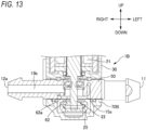
- FIG. 13 is a partial cross-sectional view of the electromagnetic valve 1B.
- the electromagnetic valve 1B is different from the electromagnetic valve 1A according to the first embodiment in the second component 70. Therefore, in the following description, portions different from those of the electromagnetic valve 1A will be mainly described, and a description of common portions will be appropriately omitted.
- a second component 70B of the electromagnetic valve 1B does not include the second outflow portion 12b and the third connection portion 72 of the electromagnetic valve 1A. Therefore, in the electromagnetic valve 1B, the third flow path 15c in the electromagnetic valve 1A is not formed.
- the opening and closing portion 25 does not contact the contact portion 62a of the first component 50, and the first opening 62 is opened. That is, in the open state, a fluid is allowed to flow from the first flow path 15a to the second flow path 15b through the first opening 62, and the fluid is allowed to flow out from the first outflow portion 12a.
- an electromagnetic valve can be easily changed from a method of switching between two flow paths to a method of switching ON/OFF of fluid supply to one flow path only by changing the second component 70 in the electromagnetic valve 1A according to the first embodiment.
- the electromagnetic valve 1B is configured as a normally open electromagnetic valve. Further, components other than the second component 70 in the electromagnetic valve 1A according to the first embodiment can be used as they are. Further, the operations and effects described in the first embodiment are similarly exhibited in the second embodiment as long as the operations and effects do not contradict with those of the electromagnetic valve 1B.
- FIG. 14 is a partial cross-sectional view of the electromagnetic valve 1C.
- the electromagnetic valve 1C is different from the electromagnetic valve 1A according to the first embodiment in the first component 50. Therefore, in the following description, portions different from those of the electromagnetic valve 1A will be mainly described, and a description of common portions will be appropriately omitted.
- a first component 50C of the electromagnetic valve 1C does not include the first outflow portion 12a and the second connection portion 52 of the electromagnetic valve 1A. Therefore, in the electromagnetic valve 1C, the second flow path 15b in the electromagnetic valve 1A is not formed.
- the electromagnetic valve 1C is in a closed state when power is not supplied, the movable element 22 is pushed out by a biasing member, and the opening and closing portion 25 comes into contact with the contact portion 82a of the second component 70 to close the second opening 82. That is, in the closed state, flow of a fluid to the third flow path 15c via the second opening 82 and outflow of the fluid from the second outflow portion 12b are prevented.
- the movable element 22 is attracted toward the coil 21, the opening and closing portion 25 is separated from the contact portion 82a of the second component 70, and the second opening 82 is opened. That is, the fluid is allowed to flow from the first flow path 15a to the third flow path 15c through the second opening 82, and the fluid is allowed to flow out from the second outflow portion 12b.
- an electromagnetic valve can be easily changed from a method of switching between two flow paths to a method of switching ON/OFF of fluid supply to one flow path only by changing the first component 50 in the electromagnetic valve 1A according to the first embodiment.
- the electromagnetic valve 1C is configured as a normally closed electromagnetic valve. Further, components other than the first component 50 in the electromagnetic valve 1A according to the first embodiment can be used as they are. Further, the operations and effects described in the first embodiment are similarly exhibited in the third embodiment as long as the operations and effects do not contradict with those of the electromagnetic valve 1C.
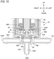
- FIG. 15 is a partial cross-sectional view of the electromagnetic valve 1D.
- the electromagnetic valve 1D is different from the electromagnetic valve 1A according to the first embodiment in the first component 50 and the second component 70. Further, the seal portion 90 and the solenoid housing 30 are also slightly different.
- a first component 50D and a second component 70D different from those of the electromagnetic valve 1A will be mainly described, and a description of common portions will be appropriately omitted.
- the first component 50D of the electromagnetic valve 1D is not provided with the inflow portion 11, the first outflow portion 12a, the first connection portion 51, and the second connection portion 52 of the electromagnetic valve 1A.
- the first component 50D includes an enclosure portion 54D that defines a part of an outer edge of the flow path 15D inside the first component 50D.
- the second component 70D includes an inflow portion 11D, a first outflow portion 12aD, a second outflow portion 12bD, a first connection portion 51D connected to the inflow portion 11D, a second connection portion 52D connected to the first outflow portion 12aD, and a third connection portion 72D connected to the second outflow portion 12bD.
- the second component 70D is provided with the second opening 82 bordered by the contact portion 82a that can come into contact with the opening and closing portion 25 of the movable element 22.
- the second component 70D is provided with a partition portion 53D that partitions an inner space and an outer space in the radial direction.
- the partition portion 53D is connected to the second opening 82.
- the inner space partitioned by the partition portion 53D is connected to the third connection portion 72D.
- the outer space partitioned by the partition portion 53D is connected to the first connection portion 51D and the second connection portion 52D.
- a first flow path 15aD is formed by the outer space partitioned by the partition portion 53D of the second component 70D and a space surrounded by the enclosure portion 54 of the first component 50D and the seal portion 90D.
- the seal portion 90D has the same configuration as the seal portion 90 of the electromagnetic valve 1A except that the seal portion 90D does not include a portion outside the second fitting portion 93 in the radial direction.
- a second flow path 15bD is formed by the inner space of the partition portion 53D of the second component 70D and a space inside the second connection portion 52D.
- the movable element 22 In a case in which the electromagnetic valve 1D is in a closed state when power is not supplied, the movable element 22 is pushed out by a biasing member, and the opening and closing portion 25 comes into contact with the contact portion 82a of the second component 70 to close the second opening 82. That is, in the closed state, flow of a fluid to the second flow path 15bD via the second opening 82 and outflow of the fluid from the second outflow portion 12bD are prevented.
- the electromagnetic valve 1D In a case in which the electromagnetic valve 1D is in an open state when the power is supplied, the movable element 22 is attracted toward the coil 21, the opening and closing portion 25 is separated from the contact portion 82a of the second component 70D, and the second opening 82 is opened.
- the fluid is allowed to flow from the first flow path 15aD to the second flow path 15bD through the second opening 82, and the fluid is allowed to flow out from the second outflow portion 12bD.
- the fluid is allowed to flow to the first outflow portion 12aD.
- a specification of an electromagnetic valve can be changed from a method of switching between two flow paths to a method of switching circulation to one flow path by changing the first component 50 and the second component 70 while using common components such as the solenoid 20 and the solenoid housing 30 of the electromagnetic valve 1A in the electromagnetic valve 1D. Further, the operations and effects described in the first embodiment are similarly exhibited in the fourth embodiment as long as the operations and effects do not contradict with those of the electromagnetic valve 1D.
- FIG. 16 is a view showing a first connection example of the electromagnetic valve.
- FIG. 17 is a view showing a second connection example of the electromagnetic valve.
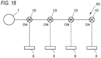
- FIG. 18 is a view showing a third connection example of the electromagnetic valve.
- FIG. 16 shows a cleaner system 9A including a tank 7, a plurality of cleaner units 8, and the electromagnetic valves 1B and 1C.
- a system can be constructed by combining the normally open electromagnetic valve 1B and the normally closed electromagnetic valve 1C according to a cleaning target and a priority of the cleaner unit 8, and expandability of the electromagnetic valves 1B and 1C in constructing the system is high.
- FIG. 17 shows a cleaner system 9B including the tank 7, the plurality of cleaner units 8, and a plurality of the electromagnetic valves 1A.
- a small number of the electromagnetic valves 1A capable of switching between the two flow paths can switch fluid supply to the plurality of cleaner units 8. Further, the normally open flow path and the normally closed flow path can be selected according to the cleaning target and the priority of the cleaner unit 8, and the expandability in constructing the system is high.
- FIG. 18 shows a cleaner system 9C including the tank 7, the plurality of cleaner units 8, and a plurality of the electromagnetic valves 1D.
- the cleaner system 9C can also be constructed by disposing, at a branch point of the flow path, the electromagnetic valve 1D capable of switching the flow of the fluid to one flow path while allowing the flow of the fluid to another flow path.
- the electromagnetic valve including the first component having a rectangular shape when viewed from a bottom surface side
- the electromagnetic valve may have another shape as long as the functions and effects are not inconsistent.
- a polygonal shape other than the rectangular shape or a shape in which a part of surfaces are rounded may be used.
- the flow path forming portion includes the first component and the second component
- the flow path forming portion may include one component as long as the functions and effects are not inconsistent.
- the configuration including two outflow portions has been described, but the configuration including one outflow portion as shown in the second embodiment and the third embodiment may be used.
- the second component includes the first lock portion extending in the axial direction to the position where the second lock portion of the solenoid housing is provided has been described, but an opposite aspect may be adopted as long as the operations and effects are not inconsistent.
- the second component may be provided with the first lock portion protruding in the radial direction
- the solenoid housing may be provided with the second lock portion that extends in the axial direction to a position where the first lock portion of the second component is provided and is locked to the first lock portion.
- seal portion has been described, but it is possible to change the seal portion as appropriate within a range that does not contradict the operations and effects.
- the O-ring or the like may be adopted instead of the above-described seal portion including the bent portion.
- the sheet portion and the third fitting portion may be omitted, and the seal portion may include the first fitting portion, the bent portion, and the second fitting portion.
- the communication passage of the solenoid housing opens on the surface facing the flow path forming portion
- the communication passage may open to the other surface as long as the operations and effects are not inconsistent. Further, the communication passage may not be provided as long as the operations and effects are not inconsistent.
- Japan patent application Japanese Patent Application No. 2021 - 009604 , Japanese Patent Application No. 2021-009605 , Japanese Patent Application No. 2021-009606 , Japanese Patent Application No. 2021-009607 , and Japanese Patent Application No. 2021-009608 filed on January 25, 2021 , and the contents of which are incorporated herein by reference. Further, the contents thereof are incorporated in their entirety herein by reference.
Landscapes
- Engineering & Computer Science (AREA)
- General Engineering & Computer Science (AREA)
- Mechanical Engineering (AREA)
- Physics & Mathematics (AREA)
- Electromagnetism (AREA)
- Magnetically Actuated Valves (AREA)
Abstract
Description
- The present invention relates to an electromagnetic valve.
-
Patent Literature 1 discloses an electromagnetic valve including a solenoid, a sealing portion provided on a movable element, a first pipe, and a second pipe. - Patent Literature 1:
JP2020-94622A - In the electromagnetic valve of
Patent Literature 1, one component defines a flow path of a fluid in the electromagnetic valve. For example, it is not easy to change a specification of the electromagnetic valve. - In the electromagnetic valve of
Patent Literature 1, a seal member that is in sliding contact with an outer peripheral surface of the movable element is provided such that the fluid does not flow to a coil side. On the other hand, since the movable element slides with respect to the seal member, electric power required to move the movable element increases. - In the electromagnetic valve of
Patent Literature 1, a seal member that is in sliding contact with an outer peripheral surface of the movable element is provided such that the fluid does not flow to a coil side. - An object of a first aspect of the present invention is to provide an electromagnetic valve in which strength of a portion supporting a component can be easily ensured and a specification can be easily changed.
- An object of a second aspect of the present invention is to provide an electromagnetic valve of which a specification can be easily changed.
- An object of a third aspect of the present invention is to provide an electromagnetic valve capable of preventing an increase in distance between components.
- An object of a fourth aspect of the present invention is to provide an electromagnetic valve capable of preventing a fluid from flowing to a coil side and capable of operating a movable element with less electric power.
- An object of a fifth aspect of the present invention to provide an electromagnetic valve capable of preventing movement of a movable element from being hindered.
- An electromagnetic valve according to one aspect of the present invention including:
- a flow path forming portion including an inflow portion into which a fluid flows and at least one outflow portion from which the fluid flows out, in which the fluid flows;
- a solenoid including a coil and a movable element capable of reciprocating in an axial direction with respect to the coil; and
- a solenoid housing accommodating at least the coil, in which
- the electromagnetic valve is configured to switch between, by reciprocation of the movable element, a closed state in which the fluid is prevented from flowing out of the outflow portion and an open state in which the fluid is allowed to flow out of the outflow portion,
- the flow path forming portion includes a first component and a second component,
- the solenoid housing, the first component, and the second component are arranged in this order in the axial direction,
- the first component is provided with a connection portion that allows the fluid to flow between the flow path forming portion and an outside,
- the solenoid housing and the second component are provided with supporting portions supporting each other,
- each of the supporting portions includes a first lock portion extending in the axial direction and a second lock portion engaging with the first lock portion to prevent mutual displacement in the axial direction, and
- when a first end portion and a second end portion located on an opposite side of the first end portion are defined on at least one of sides of the first component that is present in a cross section passing through the connection portion and extending in a direction perpendicular to the axial direction, the first lock portion is located on a first end portion side, and a space through which the connection portion passes is provided from the first lock portion to a second end portion side.
- Since the first lock portion is located on at least one first end portion in the cross section passing through the connection portion and extending in the direction perpendicular to the axial direction, and the space through which the connection portion passes is provided from the first lock portion to the second end portion side, the connection portion that allows the fluid to flow between the flow path forming portion and the outside can be extended from the first component. Further, compared to a configuration in which the connection portion is sandwiched between a plurality of the first lock portions on a side on which the connection portion is provided, even when the connection portion is enlarged, a width of the first lock portion is easily ensured, and strength is easily ensured. Further, when the space provided from the first lock portion to the second end portion side is sufficiently large, the connection portion can be switched to a small or large connection portion only by replacing the first component without changing a specification of the supporting portion.
- An electromagnetic valve according to one aspect of the present invention, including:
- a flow path forming portion including an inflow portion into which a fluid flows and at least one outflow portion from which the fluid flows out, in which the fluid flows;
- a solenoid including a coil and a movable element capable of reciprocating in an axial direction with respect to the coil; and
- a solenoid housing accommodating at least the coil, in which
- the electromagnetic valve is configured to switch between, by reciprocation of the movable element, a closed state in which the fluid is prevented from flowing out of the outflow portion and an open state in which the fluid is allowed to flow out of the outflow portion,
- the flow path forming portion includes a first component and a second component, and
- the first component and the second component form a flow path.
- The electromagnetic valve includes the flow path forming portion including the first component and the second component, and the solenoid housing, and the first component and the second component forms the flow path, and thus by replacing at least one of the first component and the second component, it is possible to easily change a specification such as the number of switchable flow paths while using common portions such as the solenoid and the solenoid housing.
- An electromagnetic valve according to one aspect of the present invention, including:
- a flow path forming portion including an inflow portion into which a fluid flows and at least one outflow portion from which the fluid flows out, in which the fluid flows;
- a solenoid including a coil and a movable element capable of reciprocating in an axial direction with respect to the coil; and
- a solenoid housing accommodating at least the coil, in which
- the electromagnetic valve is configured to switch between, by reciprocation of the movable element, a closed state in which the fluid is prevented from flowing out of the outflow portion and an open state in which the fluid is allowed to flow out of the outflow portion,
- the flow path forming portion includes a first component and a second component,
- the solenoid housing, the first component, and the second component are arranged in this order in the axial direction,
- an elastic member is provided between the solenoid housing and the first component, and the first component is provided so as to be movable in the axial direction relative to the solenoid housing,
- the solenoid housing and the second component are respectively provided with first movement restriction portions that restrict relative movement in a direction away from each other, and
- the first component and the second component are respectively provided with second movement restriction portions that restrict relative movement in a direction away from each other.
- In the configuration in which the flow path forming portion includes the first component and the second component, and the first component is movable relative to the solenoid housing by the elastic member, the first movement restriction portions and the second movement restriction portions are provided. The first movement restriction portions restrict the relative movement of the solenoid housing and the second component in the direction away from each other, and the second movement restriction portions restrict the relative movement of the first component and the second component in the direction away from each other. Therefore, it is possible to prevent the first component from moving relative to the solenoid housing and to prevent an increase in distance between the first component and the second component.
- An electromagnetic valve according to one aspect of the present invention, including:
- a flow path forming portion including an inflow portion into which a fluid flows and at least one outflow portion from which the fluid flows out, in which the fluid flows; and
- a solenoid including a coil and a movable element capable of reciprocating in an axial direction with respect to the coil, in which
- the electromagnetic valve is configured to switches between, by reciprocation of the movable element, a closed state in which the fluid is prevented from flowing out of the outflow portion and an open state in which the fluid is allowed to flow out of the outflow portion, and
- a seal portion that expands and contracts in accordance with the reciprocation of the movable element and prevents the fluid from flowing from the flow path forming portion to the coil is provided.
- By providing the seal portion, it is possible to prevent the flow of the fluid from the flow path forming portion to the coil. Further, since the seal portion extends and contracts in accordance with the reciprocation of the movable element, the movable element can be operated with less electric power than, for example, a case of using a structure in which the seal portion does not expand and contract and slides on the movable element.
- An electromagnetic valve according to one aspect of the present invention, including:
- a flow path forming portion including an inflow portion into which a fluid flows and at least one outflow portion from which the fluid flows out, in which the fluid flows;
- a solenoid including a coil and a movable element capable of reciprocating in an axial direction with respect to the coil; and
- a solenoid housing accommodating at least the coil, in which
- the electromagnetic valve is configured to switch between, by reciprocation of the movable element, a closed state in which the fluid is prevented from flowing out of the outflow portion and an open state in which the fluid is allowed to flow out of the outflow portion,
- the movable element is capable of reciprocating in the axial direction through an opening provided in the solenoid housing,
- a seal portion configured to prevent the fluid from flowing into the solenoid housing from the flow path forming portion is provided between the movable element and the opening, and
- the solenoid housing includes a communication passage that allows gas to flow between an inside and an outside thereof.
- In the electromagnetic valve in which the seal portion is provided between the movable element and the opening to prevent the fluid from flowing into the solenoid housing from the flow path forming portion, the solenoid housing includes the communication passage that allows the gas to flow between the inside and the outside thereof, and it is possible to prevent movement of the movable element from being hindered by a pressure difference between the inside and outside of the solenoid housing.
- According to the first aspect of the present invention, it is possible to provide an electromagnetic valve in which strength of a portion supporting a component can be easily ensured and a specification can be easily changed.
- According to the second aspect of the present disclosure, it is possible to provide an electromagnetic valve of which a specification can be easily changed.
- According to the third aspect of the present disclosure, it is possible to provide an electromagnetic valve capable of preventing an increase in distance between components.
- According to the fourth aspect of the present invention, it is possible to provide an electromagnetic valve capable of preventing a fluid from flowing to a coil side and operating a movable element with less electric power.
- According to the fifth aspect of the present disclosure, it is possible to provide an electromagnetic valve capable of preventing movement of a movable element from being hindered.
-
- [
FIG. 1] FIG. 1 is a perspective view of an electromagnetic valve according to a first embodiment. - [
FIG. 2] FIG. 2 is a front view of the electromagnetic valve according to the first embodiment. - [
FIG. 3] FIG. 3 is a left side view of the electromagnetic valve according to the first embodiment. - [
FIG. 4] FIG. 4 is a right side view of the electromagnetic valve according to the first embodiment. - [
FIG. 5] FIG. 5 is a bottom view of the electromagnetic valve according to the first embodiment. - [
FIG. 6] FIG. 6 is a cross-sectional view taken along an arrow direction of a line VI-VI inFIG. 2 . - [
FIG. 7] FIG. 7 is a cross-sectional view taken along an arrow direction of a line V-V inFIG. 5 in a first state. - [
FIG. 8] FIG. 8 is a cross-sectional view taken along the arrow direction of the line V-V inFIG. 5 in a second state. - [
FIG. 9] FIG. 9 is a cross-sectional view taken along an arrow direction of a line VII-VII inFIG. 2 in the first state. - [
FIG. 10] FIG. 10 is a cross-sectional view taken along an arrow direction of a line VIII-VIII inFIG. 2 in the first state. - [
FIG. 11] FIG. 11 is a cross-sectional view taken along an arrow direction of a line IX-IX inFIG. 2 . - [
FIG. 12] FIG. 12 is an exploded perspective view of a solenoid housing, a seal portion, and a first component. - [
FIG. 13] FIG. 13 is a partial cross-sectional view of an electromagnetic valve according to a second embodiment. - [
FIG. 14] FIG. 14 is a partial cross-sectional view of an electromagnetic valve according to a third embodiment. - [
FIG. 15] FIG. 15 is a partial cross-sectional view of an electromagnetic valve according to a fourth embodiment. - [
FIG. 16] FIG. 16 is a schematic view showing a first connection example of an electromagnetic valve according to an embodiment. - [
FIG. 17] FIG. 17 is a schematic view showing a second connection example of an electromagnetic valve according to the embodiment. - [
FIG. 18] FIG. 18 is a schematic view showing a third connection example of an electromagnetic valve according to the embodiment. - Hereinafter, embodiments of the present invention will be described with reference to the drawings. Members having the same reference numerals as those already described in the description of the present embodiment will be omitted for convenience of description. Further, for convenience of description, the dimensions of the members shown in the drawings may be different from actual dimensions of the members.
-
FIG. 1 is a perspective view of anelectromagnetic valve 1A according to a first embodiment.FIG. 2 is a front view of theelectromagnetic valve 1A.FIG. 3 is a left side view of theelectromagnetic valve 1A.FIG. 4 is a right side view of theelectromagnetic valve 1A.FIG. 5 is a bottom view of theelectromagnetic valve 1A.FIG. 6 is a cross-sectional view of theelectromagnetic valve 1A taken along an arrow direction of a line VI-VI inFIG. 2 .FIG. 7 is a cross-sectional view of theelectromagnetic valve 1A in a first state to be described later, which is taken along an arrow direction of a line V-V inFIG. 5 . Theelectromagnetic valve 1A is mounted, for example, on a cleaner that cleans a vehicle lamp which is mounted on a vehicle, an on-vehicle sensor, or a windshield of the vehicle. Alternatively, theelectromagnetic valve 1A is mounted on a cleaner that cleans a monitoring camera. Alternatively, theelectromagnetic valve 1A is mounted on a cleaner that cleans a sensor that is attached to a structure provided on ground such as a traffic light or a street light and acquires traffic information. Examples of the sensor to be cleaned include a camera, a LiDAR, and a radar. LiDAR is an abbreviation of light detection and ranging or laser imaging detection and ranging. - As shown in
FIG. 7 , theelectromagnetic valve 1A includes a flowpath forming portion 10 and asolenoid 20. The flowpath forming portion 10 includes aninflow portion 11 into which a fluid flows, afirst outflow portion 12a from which the fluid flows out, and asecond outflow portion 12b. Thesolenoid 20 includes acoil 21, amovable element 22, and a biasingmember 28. Themovable element 22 can reciprocate along an axial direction. - When the
coil 21 is not energized (when thesolenoid 20 is not energized), themovable element 22 is pressed toward the flowpath forming portion 10 by an elastic restoring force of the biasingmember 28. When thecoil 21 is energized (thesolenoid 20 is energized), themovable element 22 moves toward thecoil 21 against the elastic restoring force of the biasingmember 28. - In the following description, each direction is defined based on an axial direction in which a movement axis A of the
movable element 22 extends. Acoil 21 side in the axial direction is referred to as an upper side. A flowpath forming portion 10 side in the axial direction is referred to as a lower side. Further, a direction orthogonal to the axial direction is referred to as a radial direction, and a rotation direction around the axial direction is referred to as a circumferential direction. Further, front, rear, left, and right directions are defined provisionally as shown in each figure. - The
electromagnetic valve 1A can be switched between a first state and a second state by reciprocation of themovable element 22. In the first state, the fluid is allowed to flow out from thefirst outflow portion 12a, and is prevented from flowing out from thesecond outflow portion 12b. In the second state, the fluid is allowed to flow out from thesecond outflow portion 12b, and is prevented from flowing out from thefirst outflow portion 12a. - As shown in
FIG. 7 , theelectromagnetic valve 1A includes asolenoid housing 30 that accommodates at least thecoil 21. Thesolenoid housing 30 includes anaccommodating portion 36 that accommodates at least thecoil 21, and a sealingmember 37 that seals an upper side of theaccommodating portion 36. Thesolenoid housing 30 is provided with anopening 32 that opens downward. Themovable element 22 extends to an outside of thesolenoid housing 30 through theopening 32. Aguide portion 26 that guides themovable element 22 in the axial direction is disposed in thesolenoid housing 30. Theguide portion 26 is in contact with a guidedportion 23 provided on themovable element 22. - The flow
path forming portion 10 includes afirst component 50 and asecond component 70. Thefirst component 50 and thesecond component 70 constitute aflow path 15 that guides the fluid from theinflow portion 11 to thefirst outflow portion 12a and thesecond outflow portion 12b. - The
solenoid housing 30, thefirst component 50, and thesecond component 70 are arranged in this order from above to below in the axial direction. In the illustrated example, aseal portion 90 that is an elastic member is provided between thesolenoid housing 30 and thefirst component 50. Theseal portion 90 is pressed by pressingportions 90a provided on thesolenoid housing 30 and thefirst component 50, respectively. - The
solenoid housing 30 and thesecond component 70 are provided with supportingportions 17 that support each other. The supportingportions 17 support thesolenoid housing 30 and thesecond component 70 with thefirst component 50 interposed therebetween in a manner of not being displaceable in the axial direction. - An O-
ring 5 is provided between thefirst component 50 and thesecond component 70. Each of thefirst component 50 and thesecond component 70 is provided with apressing portion 5a that presses the O-ring 5 in the axial direction. - The
first component 50 includes anupper opening 50a adjacent to theopening 32 of thesolenoid housing 30 with theseal portion 90 interposed therebetween, and alower opening 50b adjacent to thesecond component 70. Themovable element 22 extending outward from theopening 32 of thesolenoid housing 30 is inserted into thefirst component 50 through theupper opening 50a of thefirst component 50. - As shown in
FIG. 6 , thefirst component 50 has a rectangular shape when viewed in the axial direction. Thefirst component 50 includes theinflow portion 11 and thefirst outflow portion 12a. As shown inFIGS. 3 ,4 , and6 , thefirst component 50 is provided with a pair of first side surfaces 55 facing each other. Afirst connection portion 51 is provided on onefirst side surface 55. Asecond connection portion 52 is provided on the otherfirst side surface 55. Thefirst connection portion 51 is connected to theinflow portion 11. Thesecond connection portion 52 is connected to thefirst outflow portion 12a. Thefirst connection portion 51 and thesecond connection portion 52 are tubular portions extending leftward and rightward from thefirst side surface 55, respectively. - As shown in
FIG. 7 , thefirst component 50 is provided with afirst opening 62 and apartition portion 53. Thefirst opening 62 is bordered by acontact portion 62a that is in contact with an opening and closingportion 25 provided at a tip of themovable element 22. Thepartition portion 53 extends downward from above. As shown inFIGS. 6 and7 , thepartition portion 53 partitions a space inside thefirst component 50 constituting a part of theflow path 15 into an inner space 50I and anouter space 500 in the radial direction. Thepartition portion 53 is connected to theupper opening 50a and thefirst opening 62. The inner space 50I and theouter space 500 are connected to each other via a lower side of thepartition portion 53. Themovable element 22 extends in the inner space 50I. Thepartition portion 53 is provided with aflow hole 53a that connects the inner space 50I and an internal space of thesecond connection portion 52. - The
first component 50 includes anenclosure portion 54 that defines an outer peripheral edge of theouter space 500. Theenclosure portion 54 is connected to thelower opening 50b. Theenclosure portion 54 is provided with aflow hole 54a that connects theouter space 500 and an internal space of thefirst connection portion 51. - The
second component 70 includes thesecond outflow portion 12b. Thesecond component 70 is provided with athird connection portion 72 connected to thesecond outflow portion 12b. Thethird connection portion 72 is a tubular portion extending in the axial direction. Thesecond component 70 has anupper opening 70a adjacent to thelower opening 50b of thefirst component 50. Thesecond component 70 is provided with asecond opening 82 bordered by acontact portion 82a that can come into contact with the opening and closingportion 25 of themovable element 22. The third connection portion is connected to thesecond opening 82. Thesecond component 70 includes anenclosure portion 74 that defines an internal space of thesecond component 70 that forms a part of theflow path 15. Theenclosure portion 74 is connected to theupper opening 70a and thesecond opening 82. Theenclosure portion 74 has a larger diameter than thesecond opening 82. Thefirst component 50 and thesecond component 70 are adjacent to each other with the O-ring 5 interposed therebetween such that an outer edge of theflow path 15 is formed by theenclosure portion 54 of thefirst component 50 and theenclosure portion 74 of thesecond component 70. When theelectromagnetic valve 1A is in either the first state or the second state, the opening and closingportion 25 of themovable element 22 is located between thefirst component 50 and thesecond component 70. Specifically, the opening and closingportion 25 is located between thefirst opening 62 and thesecond opening 82. - The
seal portion 90 is an elastic member that expands and contracts in accordance with the reciprocation of themovable element 22 and prevents the fluid from flowing from the flowpath forming portion 10 to thecoil 21. Theseal portion 90 is provided to partition themovable element 22 and theopening 32 of thesolenoid housing 30. Theseal portion 90 includes a firstfitting portion 91 fixed to themovable element 22 and a secondfitting portion 93 fixed to the flowpath forming portion 10. The firstfitting portion 91 is fixed to agroove portion 24 provided in themovable element 22. The secondfitting portion 93 is also fixed to thesolenoid housing 30. The firstfitting portion 91 and the secondfitting portion 93 are each formed in a frame shape. The firstfitting portion 91 and the secondfitting portion 93 are connected to each other by abent portion 92. The firstfitting portion 91 is smaller in size in the radial direction than the secondfitting portion 93, and is provided inside the secondfitting portion 93. In the present embodiment, the firstfitting portion 91 and the secondfitting portion 93 are each formed in a circular shape (seeFIG. 12 to be described later), and a diameter of the firstfitting portion 91 is smaller than a diameter of the secondfitting portion 93. - The first
fitting portion 91 may be directly fixed to themovable element 22, or may be indirectly fixed to themovable element 22 via another member fixed to themovable element 22. Similarly, the secondfitting portion 93 may be directly or indirectly fixed to thefirst component 50 forming the flowpath forming portion 10. Further, the secondfitting portion 93 may be directly or indirectly fixed to thesolenoid housing 30 of which a positional relationship with respect to the flowpath forming portion 10 does not change. In this description, the expression "fixed to the flowpath forming portion 10" means that it is fixed such that a position thereof relative to the flowpath forming portion 10 is not changed. Further, in the present description, the expression "fixed to thesolenoid housing 30" means that it is fixed such that a position thereof relative to thesolenoid housing 30 is not changed. In the present embodiment, theseal portion 90 includes a sheet-shaped portion and a tubular portion provided at a center of the sheet-shaped portion and extending vertically from the sheet-shaped portion. The firstfitting portion 91 is provided in the tubular portion, and the secondfitting portion 93 is provided in the sheet-shaped portion. - The first
fitting portion 91 is in surface contact with themovable element 22. Specifically, a flat portion 91a extending in an axial direction of the firstfitting portion 91 is fitted into thegroove portion 24 of themovable element 22 to achieve the surface contact. The secondfitting portion 93 is fixed to the flowpath forming portion 10 by being sandwiched between thesolenoid housing 30 and the flowpath forming portion 10. Specifically, the secondfitting portion 93 is pressed by thepressing portion 90a of thesolenoid housing 30 and thepressing portion 90a of thefirst component 50. The secondfitting portion 93 is fixed outward of theopening 32 of thesolenoid housing 30 and theupper opening 50a of thefirst component 50, in the radial direction. The secondfitting portion 93 has a thickness in the axial direction larger than that of another portion of theseal portion 90. - The
seal portion 90 separates aspace 90U on thecoil 21 side from aspace 90L on theflow path 15 side. The guidedportion 23 of themovable element 22 is provided at a portion located in thespace 90U. Theflow path 15 is defined by theseal portion 90, thefirst component 50, and thesecond component 70. Theflow path 15 includes afirst flow path 15a, asecond flow path 15b, and athird flow path 15c. Thefirst flow path 15a refers to a flow path from theinflow portion 11 to thefirst opening 62 of the first component and thesecond opening 82 of the second component. Thesecond flow path 15b refers to a flow path from thefirst opening 62 of the first component to thefirst outflow portion 12a. Thethird flow path 15c refers to a flow path from thesecond opening 82 of the second component to thesecond outflow portion 12b. - Next, an operation of the
electromagnetic valve 1A will be described. The first state of theelectromagnetic valve 1A illustrated inFIG. 7 is a state in which thecoil 21 is not energized, themovable element 22 is pushed out by the biasingmember 28, and the opening and closingportion 25 comes into contact with thecontact portion 82a of thesecond component 70 to close thesecond opening 82. In the first state, the opening and closingportion 25 is not in contact with thecontact portion 62a of thefirst component 50, and thefirst opening 62 is in an open state. That is, in the first state, the fluid is allowed to flow from thefirst flow path 15a to thesecond flow path 15b through thefirst opening 62, and the fluid is allowed to flow out from thefirst outflow portion 12a. On the other hand, in the first state, flow of the fluid to thethird flow path 15c via thesecond opening 82 and outflow of the fluid from thesecond outflow portion 12b are prevented. -
FIG. 8 is a cross-sectional view of theelectromagnetic valve 1A in a second state, which is taken along the arrow direction of the line V-V inFIG. 5 . The second state of theelectromagnetic valve 1A illustrated inFIG. 8 is a state in which thecoil 21 is energized, themovable element 22 is attracted to thecoil 21 side, the opening and closingportion 25 comes into contact with thecontact portion 62a of thefirst component 50 to close thefirst opening 62. In the second state, the opening and closingportion 25 is not in contact with thecontact portion 82a of thesecond component 70, and thesecond opening 82 is in an open state. That is, in the second state, the fluid is allowed to flow from thefirst flow path 15a to thethird flow path 15c through thesecond opening 82, and the fluid is allowed to flow out from thesecond outflow portion 12b. On the other hand, in the second state, flow of the fluid to thesecond flow path 15b via thefirst opening 62 and outflow of the fluid from thefirst outflow portion 12a are prevented. - When the
electromagnetic valve 1A transitions from the first state to the second state (transitions fromFIG. 7 to FIG. 8 ), thebent portion 92 of theseal portion 90 is deformed, and themovable element 22 is attracted toward thecoil 21. When theelectromagnetic valve 1A transitions from the second state to the first state (when theelectromagnetic valve 1A transitions fromFIG. 8 to FIG. 7 ), thebent portion 92 of theseal portion 90 returns to an original shape, and themovable element 22 is pushed out to a flowpath forming portion 10 side. - Next, the supporting
portion 17 provided on thesolenoid housing 30 and thesecond component 70 will be described with reference toFIGS. 2 to 4 ,9 , and10 .FIG. 9 is a cross-sectional view of theelectromagnetic valve 1A in the first state, which is taken along an arrow direction of a line VII-VII inFIG. 2 .FIG. 10 is a cross-sectional view of theelectromagnetic valve 1A in the first state, which is taken along an arrow direction of a line VIII-VIII inFIG. 2 . As shown inFIGS. 2 to 4 , the supportingportion 17 includes afirst lock portion 71 provided on thesecond component 70 and a second lock portion 31 provided on thesolenoid housing 30. Thefirst lock portion 71 is a portion extending in the axial direction. The second lock portion 31 engages with thefirst lock portion 71 to restrict mutual displacement in the axial direction. - The
first lock portion 71 includesfirst lock portions first lock portions 71a extend in the axial direction from a side surface of thesecond component 70 along thefirst side surface 55 of thefirst component 50 provided with thefirst connection portion 51 and the otherfirst side surface 55 of thefirst component 50 provided with thesecond connection portion 52. Thefirst lock portion 71b extends in the axial direction from a side surface of thesecond component 70 along a pair of facing second side surfaces 56 of thefirst component 50 adjacent to the first side surfaces 55. A width of thefirst lock portion 71b is larger than a width of thefirst lock portion 71a. Thefirst lock portions accommodating portion 75 capable of accommodating afirst protrusion 35 to be described later. The firstaccommodating portion 75 includes a first abuttedsurface 75a that abuts against a firstabutting surface 35a to be described later. - The second lock portion 31 is provided on a side surface of the
solenoid housing 30 along a direction in which thefirst lock portions FIG. 9 , the second lock portion 31 includes thefirst protrusion 35. Thefirst protrusion 35 is accommodated in the firstaccommodating portions 75 of thefirst lock portions solenoid housing 30 and thesecond component 70 support each other. Thefirst protrusion 35 includes the firstabutting surface 35a and a firstinclined surface 35b. The first abuttedsurface 75a, the firstabutting surface 35a, and the firstinclined surface 35b are arranged in this order in the axial direction. The firstinclined surface 35b is inclined so as to protrude from the side surface of thesolenoid housing 30 toward the firstabutting surface 35a along the axial direction. The firstabutting surface 35a extends in a direction perpendicular to the axial direction. The firstabutting surface 35a abuts against the first abuttedsurface 75a to restrict relative movement of thesolenoid housing 30 and thesecond component 70 in a direction in which thesolenoid housing 30 and thesecond component 70 are separated from each other. That is, thefirst protrusion 35 of thesolenoid housing 30 and the firstaccommodating portion 75 of thesecond component 70 constitute a firstmovement restriction portion 18 that restricts the relative movement of thesolenoid housing 30 and thesecond component 70 in the direction in which thesolenoid housing 30 and thesecond component 70 are separated from each other. The firstmovement restriction portion 18 defines a maximum separation distance between thesolenoid housing 30 and thesecond component 70. - As described above, the
seal portion 90 that is the elastic member is provided between thesolenoid housing 30 and the first component 50 (FIG. 7 ). Therefore, when theseal portion 90 is compressed, a distance between thesolenoid housing 30 and thefirst component 50 is reduced by an amount of compression. That is, thefirst component 50 is movable in the axial direction relative to thesolenoid housing 30. Therefore, in the present embodiment, a mechanism is provided to restrict thefirst component 50 from moving in the axial direction relative to thesolenoid housing 30. As shown inFIGS. 2 and10 , thefirst lock portion 71b extending along thesecond side surface 56 of thefirst component 50 includes a secondaccommodating portion 79 capable of accommodating asecond protrusion 59. The secondaccommodating portion 79 includes a second abuttedsurface 79a that abuts against a secondabutting surface 59a. - As shown in
FIGS. 2 and10 , thefirst component 50 includes thesecond protrusion 59. Thesecond protrusion 59 is accommodated in the secondaccommodating portion 79 of thefirst lock portion 71b. Thesecond protrusion 59 includes the secondabutting surface 59a and a secondinclined surface 59b. The second abuttedsurface 79a, a second abutting surface 39a, and a second inclined surface 39b are arranged in this order in the axial direction. The second inclined surface 39b is inclined so as to protrude from thesecond side surface 56 of thefirst component 50 toward the secondabutting surface 59a along the axial direction. The secondabutting surface 59a extends in a direction perpendicular to the axial direction. The secondabutting surface 59a abuts against the second abuttedsurface 79a to restrict relative movement of thefirst component 50 and thesecond component 70 in a direction in which thefirst component 50 and thesecond component 70 are separated from each other. That is, thesecond protrusion 59 of thefirst component 50 and the secondaccommodating portion 79 of thesecond component 70 constitute a secondmovement restriction portion 19 that restricts the relative movement of thefirst component 50 and thesecond component 70 in a direction in which thefirst component 50 and thesecond component 70 are separated from each other. Although thefirst component 50 is provided so as to be movable in the axial direction relative to thesolenoid housing 30, the secondmovement restriction portion 19 restricts the relative movement of thefirst component 50 and thesecond component 70 in the direction in which thefirst component 50 and thesecond component 70 are separated from each other. The firstmovement restriction portion 18 and the secondmovement restriction portion 19 are not disposed on the same straight line in the axial direction. - Next, the
first connection portion 51 and thesecond connection portion 52 provided on thefirst component 50, and thefirst lock portion 71a extending along thefirst side surface 55 of thefirst component 50 will be described with reference toFIGS. 3 ,4 , and6. FIG. 6 is a cross section extending in the direction perpendicular to the axial direction through thefirst connection portion 51 or thesecond connection portion 52. At least one ofsides 65 of thefirst component 50 appearing in this cross section defines afirst end portion 65a and asecond end portion 65b opposite thefirst end portion 65a. At this time, thefirst lock portion 71a is located on afirst end portion 65a side, and aspace 67 through which thefirst connection portion 51 or thesecond connection portion 52 passes is provided from thefirst lock portion 71a to asecond end portion 65b side. - As shown in
FIG. 6 , when viewed in the axial direction, the pair offirst lock portions 71a are disposed at positions facing each other along a direction in which a diagonal line of thefirst component 50 extends. Further, as shown inFIG. 6 , thefirst lock portions 71a are respectively disposed on the pair of first side surfaces 55 facing each other of thefirst component 50. As shown inFIGS. 3 and4 , when viewed from thefirst side surface 55 side on which thefirst connection portion 51 or thesecond connection portion 52 is provided, thefirst lock portion 71a is located on one side with respect to the movement axis A of themovable element 22, and thefirst lock portion 71a is not located on the other side. Further, thespace 67 provided on thesecond end portion 65b side from thefirst lock portion 71a is opened toward thesolenoid housing 30 in the axial direction. - Next, a ventilation mechanism of the
solenoid housing 30 of theelectromagnetic valve 1A will be described with reference toFIGS. 11 and12 .FIG. 11 is a cross-sectional view of theelectromagnetic valve 1A taken along an arrow direction of a line IX-IX inFIG. 2 .FIG. 12 is an exploded perspective view of thesolenoid housing 30, theseal portion 90, and thefirst component 50. As shown inFIGS. 11 and12 , thesolenoid housing 30 includes acommunication passage 40 that allows gas to flow between an inside and an outside thereof. Thecommunication passage 40 opens on a surface of thesolenoid housing 30 facing the flowpath forming portion 10. Thecommunication passage 40 opens at a position farther from the firstfitting portion 91 of theseal portion 90 than the secondfitting portion 93 in the radial direction orthogonal to the axial direction. - The
seal portion 90 includes asheet portion 94 extending outward from the secondfitting portion 93 in the radial direction. Theseal portion 90 includes a thirdfitting portion 95 having a frame shape fixed to thesolenoid housing 30. The thirdfitting portion 95 is thicker than thesheet portion 94 in the axial direction. The thirdfitting portion 95 is fixed by being sandwiched between thesolenoid housing 30 and thefirst component 50. The thirdfitting portion 95 is provided so as to border thesheet portion 94, and prevents the air from flowing through a gap between thesolenoid housing 30 and thefirst component 50 to a region inside the thirdfitting portion 95. - The
sheet portion 94 has a smaller thickness in the axial direction than the secondfitting portion 93 and the thirdfitting portion 95, and a gap is present between thesheet portion 94 and thesolenoid housing 30. Thecommunication passage 40 opens in thesheet portion 94 between the secondfitting portion 93 and the thirdfitting portion 95 in the radial direction orthogonal to the axial direction. Theseal portion 90 is located between the secondfitting portion 93 and the thirdfitting portion 95, and has a throughhole 96 that causes a space partitioned by theseal portion 90 where thesolenoid housing 30 is located to communicate with an outside of the space. The throughhole 96 is provided in thesheet portion 94. In an example shown inFIGS. 11 and12 , thecommunication passage 40 and the throughhole 96 overlap each other when viewed from the axial direction, but thecommunication passage 40 and the throughhole 96 may not overlap each other when viewed from the axial direction. - A
liquid storing portion 97 is formed in a space between thesolenoid housing 30 and thesheet portion 94 between the secondfitting portion 93 and the thirdfitting portion 95 of theseal portion 90. Theliquid storing portion 97 is a portion that can store a liquid when the liquid enters a space on asolenoid housing 30 side with respect to theseal portion 90 from the throughhole 96. Even if the liquid enters the throughhole 96, the liquid can be stored in theliquid storing portion 97, and the liquid is prevented from immediately entering thecommunication passage 40. - The second
fitting portion 93 and the thirdfitting portion 95 are fixed by being sandwiched between thesolenoid housing 30 and thefirst component 50, and are also fixed to the flowpath forming portion 10. Thefirst component 50 of the flowpath forming portion 10 includes aventilation portion 85 that allows the gas to flow from an outside thereof to the throughhole 96 of thesheet portion 94. Theventilation portion 85 is provided outside theenclosure portion 54 of thefirst component 50, and is a space that does not interfere with theflow path 15. Theventilation portion 85 also allows the gas to flow to thefirst component 50 from a gap which is present outside the O-ring 5 between thefirst component 50 and thesecond component 70, in the radial direction. - In the
electromagnetic valve 1A, thefirst lock portion 71a is located at least onefirst end portion 65a of theside 65 appearing in the cross section extending through thefirst connection portion 51 or thesecond connection portion 52 in the direction perpendicular to the axial direction, and thespace 67 through which thefirst connection portion 51 or thesecond connection portion 52 passes is provided from thefirst lock portion 71a to thesecond end portion 65b side. Therefore, thefirst connection portion 51 and thesecond connection portion 52 that allow the fluid to flow between the flowpath forming portion 10 and an outside thereof can be extended from thefirst component 50. Further, compared to a configuration in which thefirst connection portion 51 or thesecond connection portion 52 is sandwiched by the plurality offirst lock portions 71a on theside 65 on which thefirst connection portion 51 or thesecond connection portion 52 is provided, even when thefirst connection portion 51 or thesecond connection portion 52 is enlarged, the width of thefirst lock portion 71a is easily ensured, and strength is easily ensured. Further, when thespace 67 provided from thefirst lock portion 71a to thesecond end portion 65b side is sufficiently large, switching to the small or largefirst connection portion 51 orsecond connection portion 52 can be performed by only replacing thefirst component 50 without changing a specification of the supportingportion 17. - According to the
electromagnetic valve 1A, by disposing the pair offirst lock portions 71a at the positions facing each other along the direction in which the diagonal lines of thefirst component 50 extend, thesolenoid housing 30 and thesecond component 70 can support each other with thefirst component 50 interposed therebetween in a state in which bias is little, and an occurrence of gaps between the members can be prevented. - The
second flow path 15b and thethird flow path 15c, which are switched between an open state and a closed state, are located on the movement axis A of themovable element 22 of theelectromagnetic valve 1A. In theelectromagnetic valve 1A, when viewed from thefirst side surface 55 side on which thefirst connection portion 51 or thesecond connection portion 52 of thefirst component 50 is provided, thefirst lock portion 71a is located on one side with respect to the movement axis A of themovable element 22, and is not located on the other side. Therefore, thefirst connection portion 51 or thesecond connection portion 52 can be extended from thefirst component 50 near theflow path 15 on the movement axis A via thespace 67 in which thefirst lock portion 71a is not located. - According to the
electromagnetic valve 1A, since thespace 67 provided on thesecond end portion 65b side from thefirst lock portion 71a is open to thesolenoid housing 30 side, thefirst connection portion 51 or thesecond connection portion 52 can be easily disposed in the axial direction, and thesolenoid housing 30, thefirst component 50, and thesecond component 70 can be easily assembled. - The
electromagnetic valve 1A includes the flowpath forming portion 10 including thefirst component 50 and thesecond component 70, and thesolenoid housing 30, and theflow path 15 is formed by thefirst component 50 and thesecond component 70. Therefore, by replacing at least one of thefirst component 50 and thesecond component 70, it is possible to easily change a specification such as the number of switchable flow paths while using common portions such as thesolenoid 20 and thesolenoid housing 30. Detailed modifications will be described in a second embodiment to a fourth embodiment to be described later, but for example, an arrangement, the number and a size of the inflow portions and the outflow portions can be easily changed. Further, a specification of the electromagnetic valve such as a normally open electromagnetic valve and a normally closed electromagnetic valve can be easily changed. - As described above, according to the
electromagnetic valve 1A, many components can be used in common, and by changing only components according to specifications, a production process can be used in common. - According to the
electromagnetic valve 1A, since thesolenoid housing 30 and thesecond component 70 support each other with thefirst component 50 interposed therebetween by the supportingportions 17 provided in thesolenoid housing 30 and thesecond component 70, respectively, theelectromagnetic valve 1A can be easily disassembled by releasing the support of the supportingportions 17, and the specification can be easily changed. - In the
electromagnetic valve 1A, the supportingportion 17 of thesolenoid housing 30 includes thefirst protrusion 35, the supportingportion 17 of thesecond component 70 includes the firstaccommodating portion 75 capable of accommodating thefirst protrusion 35, and thesolenoid housing 30 and thesecond component 70 support each other by accommodating thefirst protrusion 35 in the firstaccommodating portion 75. For example, by moving the firstaccommodating portion 75 outward in the radial direction, the firstaccommodating portion 75 does not accommodate thefirst protrusion 35, so that theelectromagnetic valve 1A can be disassembled and the specification thereof can be easily changed. - According to the
electromagnetic valve 1A, since the opening and closingportion 25 is provided between thefirst component 50 and thesecond component 70 which can be disassembled, it is easy to assemble theelectromagnetic valve 1A. Further, since the opening and closingportion 25 is provided between thefirst component 50 and thesecond component 70, thefirst component 50 and thesecond component 70 are easily replaced, and the specification of theelectromagnetic valve 1A is easily changed. Further, at least one of thefirst component 50 and thesecond component 70 is provided with an opening bordered by a contact portion that can come into contact with the opening and closingportion 25, so that at least one opening can be opened and closed by the opening and closingportion 25, and the flow path can be switched. - In the first embodiment, the
inflow portion 11 is provided in thefirst component 50, and thefirst outflow portion 12a and thesecond outflow portion 12b are provided in each of thefirst component 50 and thesecond component 70. On the other hand, as in the fourth embodiment to be described later, the inflow portion may be provided in the second component. Further, as in the second embodiment to the fourth embodiment to be described later, the outflow portion may be provided in one of the first component and the second component. - In the first embodiment, the
first opening 62 and thesecond opening 82 are provided in thefirst component 50 and thesecond component 70, respectively, and the opening and closingportion 25 is located between thefirst opening 62 and thesecond opening 82. Accordingly, the flow of the fluid to the two flow paths can be switched. On the other hand, as in the second embodiment to the fourth embodiment to be described later, one of the first component and the second component may be provided with the opening bordered by the contact portion that can come into contact with the opening and closing portion. - In the
electromagnetic valve 1A, the flowpath forming portion 10 includes thefirst component 50 and thesecond component 70, and thefirst component 50 is movable relative to thesolenoid housing 30 by theseal portion 90 which is the elastic member. According to theelectromagnetic valve 1A, thesolenoid housing 30 and thesecond component 70 are provided with the firstmovement restriction portions 18 that restrict the relative movement in the direction away from each other, and thefirst component 50 and thesecond component 70 are provided with the secondmovement restriction portions 19 that restrict the relative movement in the direction away from each other, and thus it is possible to prevent thefirst component 50 from moving relative to thesolenoid housing 30 and to prevent an increase in distance between thefirst component 50 and thesecond component 70. - In the
electromagnetic valve 1A, theseal portion 90, which is the elastic member, is prevented by thepressing portions 90a of thesolenoid housing 30 and thefirst component 50, and the fluid is prevented from flowing from the flowpath forming portion 10 to thecoil 21 side. Further, although the O-ring 5 is provided between thefirst component 50 and thesecond component 70, the distance between thefirst component 50 and thesecond component 70 is short in a portion other than thepressing portions 5a that press the O-ring 5. Therefore, thefirst component 50 and thesolenoid housing 30 are prevented from relatively moving in the direction away from each other. - According to the
electromagnetic valve 1A, the firstmovement restriction portion 18 and the secondmovement restriction portion 19 are not disposed on the same straight line in the axial direction, and thus, for example, thefirst protrusion 35 can be sandwiched and supported by the firstaccommodating portion 75 in the direction perpendicular to the axial direction. - According to the
electromagnetic valve 1A, since theseal portion 90 is provided, it is possible to prevent the flow of the fluid from the flowpath forming portion 10 side to thecoil 21 side. Since theseal portion 90 extends and contracts in accordance with the reciprocation of themovable element 22, themovable element 22 can be operated with less electric power than, for example, a structure in which theseal portion 90 does not expand and contract and slides on themovable element 22. - The
seal portion 90 includes the firstfitting portion 91 fixed to themovable element 22 and the secondfitting portion 93 fixed to the flowpath forming portion 10, and thus theseal portion 90 can expand and contract along with the reciprocation of themovable element 22, and the flow of the fluid from the flowpath forming portion 10 side to thecoil 21 side can be prevented. - According to the
electromagnetic valve 1A, since the firstfitting portion 91 is in surface contact with themovable element 22, it is possible to further prevent the fluid from flowing from the flowpath forming portion 10 side to thecoil 21 side. - According to the
electromagnetic valve 1A, the secondfitting portion 93 of theseal portion 90 is sandwiched between thesolenoid housing 30 and the flowpath forming portion 10. Accordingly, theseal portion 90 can be firmly fixed with a simple structure. - According to the
electromagnetic valve 1A, since the guidedportion 23 of themovable element 22 is provided in a portion located in a space on thecoil 21 side in a space separated by theseal portion 90, it is possible to prevent the fluid from flowing from the flowpath forming portion 10 side to the guidedportion 23 of themovable element 22. - According to the
electromagnetic valve 1A, the flow of the fluid is switched between thefirst outflow portion 12a and thesecond outflow portion 12b, and the flow of the fluid from the flowpath forming portion 10 side to thecoil 21 side can be prevented by providing theseal portion 90. - In the
electromagnetic valve 1A in which theseal portion 90 is provided between themovable element 22 and theopening 32 to prevent the fluid from flowing into thesolenoid housing 30 from the flowpath forming portion 10, thesolenoid housing 30 includes thecommunication passage 40 that allows the flow of the gas between the inside and the outside thereof, and it is possible to prevent the movement of themovable element 22 from being hindered by a pressure difference between the inside and outside of thesolenoid housing 30. - According to the
electromagnetic valve 1A, since thecommunication passage 40 opens at the position farther from the firstfitting portion 91 than the secondfitting portion 93 in the direction orthogonal to the axial direction, it is possible to take external gas into thesolenoid housing 30 while theseal portion 90 provided between themovable element 22 and theopening 32 prevents the gas from flowing into thesolenoid housing 30 from the flowpath forming portion 10. - According to the
electromagnetic valve 1A, since theseal portion 90 includes the thirdfitting portion 95 having the frame shape fixed to thesolenoid housing 30, it is possible to further prevent dust, water, or the like from entering thesolenoid housing 30 from the outside through thecommunication passage 40. - According to the
electromagnetic valve 1A, since theseal portion 90 has the throughhole 96 between the secondfitting portion 93 and the thirdfitting portion 95, the gas can be circulated between the space partitioned by theseal portion 90 where thesolenoid housing 30 is located and the outside of the space, and the gas can be further circulated to thecommunication passage 40 of thesolenoid housing 30. - In the
electromagnetic valve 1A, if thecommunication passage 40 and the throughhole 96 are not overlapped with each other as viewed in the axial direction, even if the dust, the water, or the like enters, through the throughhole 96, the space partitioned by theseal portion 90 where thesolenoid housing 30 is located from the outside, it is possible to prevent the dust, the water, or the like from suddenly entering the inside of thesolenoid housing 30 through thecommunication passage 40. - According to the
electromagnetic valve 1A, theliquid storing portion 97 is formed in a space between thesolenoid housing 30 and a portion between the secondfitting portion 93 and the thirdfitting portion 95 of theseal portion 90. Therefore, even if the liquid enters, through the throughhole 96, the space partitioned by theseal portion 90 where thesolenoid housing 30 is located, the liquid is stored in theliquid storing portion 97, and thus it is possible to prevent the liquid from entering thesolenoid housing 30 via thecommunication passage 40. Further, by setting an arrangement of thecommunication passage 40 or the throughhole 96 in consideration of a fitting direction of theelectromagnetic valve 1A, it is possible to suitably prevent the liquid from entering thesolenoid housing 30. - According to the
electromagnetic valve 1A, since the flowpath forming portion 10 includes theventilation portion 85 that allows the flow of the gas from the outside thereof to the throughhole 96, the external gas can be taken into thesolenoid housing 30 through theventilation portion 85, the throughhole 96, and thecommunication passage 40, and the dust, the water, and the like can be further prevented from entering thesolenoid housing 30 through thecommunication passage 40. - Next, a configuration of an
electromagnetic valve 1B according to a second embodiment will be described with reference toFIG. 13. FIG. 13 is a partial cross-sectional view of theelectromagnetic valve 1B. Theelectromagnetic valve 1B is different from theelectromagnetic valve 1A according to the first embodiment in thesecond component 70. Therefore, in the following description, portions different from those of theelectromagnetic valve 1A will be mainly described, and a description of common portions will be appropriately omitted. - A
second component 70B of theelectromagnetic valve 1B does not include thesecond outflow portion 12b and thethird connection portion 72 of theelectromagnetic valve 1A. Therefore, in theelectromagnetic valve 1B, thethird flow path 15c in theelectromagnetic valve 1A is not formed. In a case in which theelectromagnetic valve 1B is in an open state when power is not supplied, the opening and closingportion 25 does not contact thecontact portion 62a of thefirst component 50, and thefirst opening 62 is opened. That is, in the open state, a fluid is allowed to flow from thefirst flow path 15a to thesecond flow path 15b through thefirst opening 62, and the fluid is allowed to flow out from thefirst outflow portion 12a. On the other hand, in a closed state in which theelectromagnetic valve 1B is energized, themovable element 22 is attracted toward thecoil 21, and the opening and closingportion 25 comes into contact with thecontact portion 62a of thefirst component 50 to close thefirst opening 62. That is, in the closed state, the flow of the fluid to thesecond flow path 15b via thefirst opening 62 and the outflow of the fluid from thefirst outflow portion 12a are prevented. - As described above, a specification of an electromagnetic valve can be easily changed from a method of switching between two flow paths to a method of switching ON/OFF of fluid supply to one flow path only by changing the
second component 70 in theelectromagnetic valve 1A according to the first embodiment. Theelectromagnetic valve 1B is configured as a normally open electromagnetic valve. Further, components other than thesecond component 70 in theelectromagnetic valve 1A according to the first embodiment can be used as they are. Further, the operations and effects described in the first embodiment are similarly exhibited in the second embodiment as long as the operations and effects do not contradict with those of theelectromagnetic valve 1B. - Next, a configuration of an
electromagnetic valve 1C according to a third embodiment will be described with reference toFIG. 14. FIG. 14 is a partial cross-sectional view of theelectromagnetic valve 1C. Theelectromagnetic valve 1C is different from theelectromagnetic valve 1A according to the first embodiment in thefirst component 50. Therefore, in the following description, portions different from those of theelectromagnetic valve 1A will be mainly described, and a description of common portions will be appropriately omitted. - A
first component 50C of theelectromagnetic valve 1C does not include thefirst outflow portion 12a and thesecond connection portion 52 of theelectromagnetic valve 1A. Therefore, in theelectromagnetic valve 1C, thesecond flow path 15b in theelectromagnetic valve 1A is not formed. In a case in which theelectromagnetic valve 1C is in a closed state when power is not supplied, themovable element 22 is pushed out by a biasing member, and the opening and closingportion 25 comes into contact with thecontact portion 82a of thesecond component 70 to close thesecond opening 82. That is, in the closed state, flow of a fluid to thethird flow path 15c via thesecond opening 82 and outflow of the fluid from thesecond outflow portion 12b are prevented. On the other hand, in an open state in which theelectromagnetic valve 1C is energized, themovable element 22 is attracted toward thecoil 21, the opening and closingportion 25 is separated from thecontact portion 82a of thesecond component 70, and thesecond opening 82 is opened. That is, the fluid is allowed to flow from thefirst flow path 15a to thethird flow path 15c through thesecond opening 82, and the fluid is allowed to flow out from thesecond outflow portion 12b. - As described above, a specification of an electromagnetic valve can be easily changed from a method of switching between two flow paths to a method of switching ON/OFF of fluid supply to one flow path only by changing the
first component 50 in theelectromagnetic valve 1A according to the first embodiment. Theelectromagnetic valve 1C is configured as a normally closed electromagnetic valve. Further, components other than thefirst component 50 in theelectromagnetic valve 1A according to the first embodiment can be used as they are. Further, the operations and effects described in the first embodiment are similarly exhibited in the third embodiment as long as the operations and effects do not contradict with those of theelectromagnetic valve 1C. - Next, a configuration of an
electromagnetic valve 1D according to a fourth embodiment will be described with reference toFIG. 15. FIG. 15 is a partial cross-sectional view of theelectromagnetic valve 1D. Theelectromagnetic valve 1D is different from theelectromagnetic valve 1A according to the first embodiment in thefirst component 50 and thesecond component 70. Further, theseal portion 90 and thesolenoid housing 30 are also slightly different. In the following description, afirst component 50D and asecond component 70D different from those of theelectromagnetic valve 1A will be mainly described, and a description of common portions will be appropriately omitted. - The
first component 50D of theelectromagnetic valve 1D is not provided with theinflow portion 11, thefirst outflow portion 12a, thefirst connection portion 51, and thesecond connection portion 52 of theelectromagnetic valve 1A. Thefirst component 50D includes anenclosure portion 54D that defines a part of an outer edge of the flow path 15D inside thefirst component 50D. Thesecond component 70D includes aninflow portion 11D, a first outflow portion 12aD, a second outflow portion 12bD, afirst connection portion 51D connected to theinflow portion 11D, asecond connection portion 52D connected to the first outflow portion 12aD, and athird connection portion 72D connected to the second outflow portion 12bD. Thesecond component 70D is provided with thesecond opening 82 bordered by thecontact portion 82a that can come into contact with the opening and closingportion 25 of themovable element 22. Thesecond component 70D is provided with apartition portion 53D that partitions an inner space and an outer space in the radial direction. Thepartition portion 53D is connected to thesecond opening 82. The inner space partitioned by thepartition portion 53D is connected to thethird connection portion 72D. The outer space partitioned by thepartition portion 53D is connected to thefirst connection portion 51D and thesecond connection portion 52D. - A first flow path 15aD is formed by the outer space partitioned by the
partition portion 53D of thesecond component 70D and a space surrounded by theenclosure portion 54 of thefirst component 50D and theseal portion 90D. Theseal portion 90D has the same configuration as theseal portion 90 of theelectromagnetic valve 1A except that theseal portion 90D does not include a portion outside the secondfitting portion 93 in the radial direction. A second flow path 15bD is formed by the inner space of thepartition portion 53D of thesecond component 70D and a space inside thesecond connection portion 52D. In a case in which theelectromagnetic valve 1D is in a closed state when power is not supplied, themovable element 22 is pushed out by a biasing member, and the opening and closingportion 25 comes into contact with thecontact portion 82a of thesecond component 70 to close thesecond opening 82. That is, in the closed state, flow of a fluid to the second flow path 15bD via thesecond opening 82 and outflow of the fluid from the second outflow portion 12bD are prevented. On the other hand, in a case in which theelectromagnetic valve 1D is in an open state when the power is supplied, themovable element 22 is attracted toward thecoil 21, the opening and closingportion 25 is separated from thecontact portion 82a of thesecond component 70D, and thesecond opening 82 is opened. That is, the fluid is allowed to flow from the first flow path 15aD to the second flow path 15bD through thesecond opening 82, and the fluid is allowed to flow out from the second outflow portion 12bD. In theelectromagnetic valve 1D, the fluid is allowed to flow to the first outflow portion 12aD. - As described above, a specification of an electromagnetic valve can be changed from a method of switching between two flow paths to a method of switching circulation to one flow path by changing the
first component 50 and thesecond component 70 while using common components such as thesolenoid 20 and thesolenoid housing 30 of theelectromagnetic valve 1A in theelectromagnetic valve 1D. Further, the operations and effects described in the first embodiment are similarly exhibited in the fourth embodiment as long as the operations and effects do not contradict with those of theelectromagnetic valve 1D. - Next, connection examples of the electromagnetic valve described in the embodiment will be described with reference to
FIGS. 16 to 18 .FIG. 16 is a view showing a first connection example of the electromagnetic valve.FIG. 17 is a view showing a second connection example of the electromagnetic valve.FIG. 18 is a view showing a third connection example of the electromagnetic valve. -
FIG. 16 shows acleaner system 9A including atank 7, a plurality ofcleaner units 8, and theelectromagnetic valves electromagnetic valve 1B and the normally closedelectromagnetic valve 1C according to a cleaning target and a priority of thecleaner unit 8, and expandability of theelectromagnetic valves -
FIG. 17 shows acleaner system 9B including thetank 7, the plurality ofcleaner units 8, and a plurality of theelectromagnetic valves 1A. A small number of theelectromagnetic valves 1A capable of switching between the two flow paths can switch fluid supply to the plurality ofcleaner units 8. Further, the normally open flow path and the normally closed flow path can be selected according to the cleaning target and the priority of thecleaner unit 8, and the expandability in constructing the system is high. -
FIG. 18 shows acleaner system 9C including thetank 7, the plurality ofcleaner units 8, and a plurality of theelectromagnetic valves 1D. Thecleaner system 9C can also be constructed by disposing, at a branch point of the flow path, theelectromagnetic valve 1D capable of switching the flow of the fluid to one flow path while allowing the flow of the fluid to another flow path. - Although the embodiments of the present invention have been described above, it goes without saying that the technical scope of the present invention should not be limited to the description of the present embodiments. It should be understood by those skilled in the art that the present embodiment is merely an example, and that various modifications are possible within the scope of the invention described in the claims. The technical scope of the present invention should be determined based on the scope of the invention described in the claims and the equivalent scope thereof.
- Although the electromagnetic valve including the first component having a rectangular shape when viewed from a bottom surface side has been described in the above embodiment, the electromagnetic valve may have another shape as long as the functions and effects are not inconsistent. For example, a polygonal shape other than the rectangular shape or a shape in which a part of surfaces are rounded may be used.
- In the embodiments described above, the aspect in which the flow path forming portion includes the first component and the second component has been described, but the flow path forming portion may include one component as long as the functions and effects are not inconsistent. Further, in the first embodiment and the fourth embodiment, the configuration including two outflow portions has been described, but the configuration including one outflow portion as shown in the second embodiment and the third embodiment may be used.
- In the above embodiment, the aspect in which the second component includes the first lock portion extending in the axial direction to the position where the second lock portion of the solenoid housing is provided has been described, but an opposite aspect may be adopted as long as the operations and effects are not inconsistent. For example, the second component may be provided with the first lock portion protruding in the radial direction, and the solenoid housing may be provided with the second lock portion that extends in the axial direction to a position where the first lock portion of the second component is provided and is locked to the first lock portion.
- In the above embodiment, a specific aspect of the seal portion has been described, but it is possible to change the seal portion as appropriate within a range that does not contradict the operations and effects. For example, the O-ring or the like may be adopted instead of the above-described seal portion including the bent portion. Further, for example, the sheet portion and the third fitting portion may be omitted, and the seal portion may include the first fitting portion, the bent portion, and the second fitting portion.
- In the above embodiment, the aspect in which the communication passage of the solenoid housing opens on the surface facing the flow path forming portion has been described, but the communication passage may open to the other surface as long as the operations and effects are not inconsistent. Further, the communication passage may not be provided as long as the operations and effects are not inconsistent.
- The present application is based on Japan patent application (
Japanese Patent Application No. 2021 - 009604 Japanese Patent Application No. 2021-009605 Japanese Patent Application No. 2021-009606 Japanese Patent Application No. 2021-009607 Japanese Patent Application No. 2021-009608) filed on January 25, 2021 -
- 1A, 1B, 1C, 1D: electromagnetic valve
- 2: sealing member
- 5: O-ring
- 5a: pressing portion
- 7: tank
- 8: cleaner unit
- 9A, 9B, 9C: cleaner system
- 10: flow path forming portion
- 11, 11D: inflow portion
- 12a, 12aD: first outflow portion
- 12b, 12bD: second outflow portion
- 15, 15D: flow path
- 15a, 15aD: first flow path
- 15b, 15bD: second flow path
- 15c: third flow path
- 18: first movement restriction portion
- 19: second movement restriction portion
- 20: solenoid
- 21: coil
- 22: movable element
- 23: guided portion
- 24: groove portion
- 25: opening and closing portion
- 26: guide portion
- 28: biasing member
- 30: solenoid housing
- 31: second lock portion
- 32: opening
- 35: first protrusion
- 35a: first abutting surface
- 35b: first inclined surface
- 39a: second abutting surface
- 39b: second inclined surface
- 40: communication passage
- 50, 50C, 50D: first component
- 50a: upper opening
- 50b: lower opening
- 50I: inner space
- 50O: outer space
- 51, 51D: first connection portion
- 52, 52D: second connection portion
- 53, 53D: partition portion
- 53a, 54a: flow hole
- 54, 54D: enclosure portion
- 55: first side surface
- 56: second side surface
- 59: second protrusion
- 59a: second abutting surface
- 59b: second inclined surface
- 62: first opening
- 62a: contact portion
- 65: side
- 65a: first end portion
- 65b: second end portion
- 67: space
- 70, 70B, 70B: second component
- 71: first lock portion
- 71a: first lock portion
- 71b: first lock portion
- 72, 72D: third connection portion
- 74: enclosure portion
- 75: first accommodating portion
- 75a: first abutted surface
- 79: second accommodating portion
- 79a: second abutted surface
- 82: second opening
- 82a: contact portion
- 85: ventilation portion
- 90, 90D: seal portion
- 90a: pressing portion
- 91: first fitting portion
- 91a: flat portion
- 92: bent portion
- 93: second fitting portion
- 94: sheet portion
- 95: third fitting portion
- 96: through hole
- 97: liquid storing portion
- A: movement axis
Claims (35)
- An electromagnetic valve comprising:a flow path forming portion including an inflow portion into which a fluid flows and at least one outflow portion from which the fluid flows out, in which the fluid flows;a solenoid including a coil and a movable element capable of reciprocating in an axial direction with respect to the coil; anda solenoid housing accommodating at least the coil, whereinthe electromagnetic valve is configured to switch between, by reciprocation of the movable element, a closed state in which the fluid is prevented from flowing out of the outflow portion and an open state in which the fluid is allowed to flow out of the outflow portion,the flow path forming portion includes a first component and a second component,the solenoid housing, the first component, and the second component are arranged in this order in the axial direction,the first component is provided with a connection portion that allows the fluid to flow between the flow path forming portion and an outside,the solenoid housing and the second component are provided with supporting portions supporting each other,each of the supporting portions includes a first lock portion extending in the axial direction and a second lock portion engaging with the first lock portion to prevent mutual displacement in the axial direction, andwhen a first end portion and a second end portion located on an opposite side of the first end portion are defined on at least one of sides of the first component that is present in a cross section passing through the connection portion and extending in a direction perpendicular to the axial direction, the first lock portion is located on a first end portion side, and a space through which the connection portion passes is provided from the first lock portion to a second end portion side.
- The electromagnetic valve according to claim 1, whereinthe first component has a rectangular shape when viewed from the axial direction,the connection portion is provided on each of a pair facing side surfaces of the first component, andthe first lock portion is disposed on each of the pair of facing side surfaces of the first component.
- The electromagnetic valve according to claim 2, wherein
the pair of first lock portions are disposed at positions facing each other along a direction in which a diagonal line of the first component extends when viewed from the axial direction. - The electromagnetic valve according to any one of claims 1 to 3, whereinthe first component has a rectangular shape when viewed from the axial direction,the connection portion is provided on a side surface of the first component, andthe first lock portion is located on one side with respect to a movement axis of the movable element and the first lock portion is not located on the other side with respect to the movement axis of the movable element when viewed from the side surface on which the connection portion is provided.
- The electromagnetic valve according to any one of claims 1 to 4, wherein
the space provided from the first lock portion to the second end portion side is open toward the solenoid housing. - The electromagnetic valve according to any one of claims 1 to 5, wherein
the connection portion includes a first connection portion connected to the inflow portion and a second connection portion connected to the outflow portion. - An electromagnetic valve comprising:a flow path forming portion including an inflow portion into which a fluid flows and at least one outflow portion from which the fluid flows out, in which the fluid flows;a solenoid including a coil and a movable element capable of reciprocating in an axial direction with respect to the coil; anda solenoid housing accommodating at least the coil, whereinthe electromagnetic valve is configured to switch between, by reciprocation of the movable element, a closed state in which the fluid is prevented from flowing out of the outflow portion and an open state in which the fluid is allowed to flow out of the outflow portion,the flow path forming portion includes a first component and a second component, andthe first component and the second component form a flow path.
- The electromagnetic valve according to claim 7, whereinthe solenoid housing and the second component are provided with supporting portions supporting each other, andthe solenoid housing and the second component support each other with the first component interposed therebetween, by the supporting portions.
- The electromagnetic valve according to claim 8, whereinthe supporting portion of the solenoid housing includes a protrusion,the supporting portion of the second component includes an accommodating portion capable of accommodating the protrusion, andthe solenoid housing and the second component support each other by accommodating the protrusion in the accommodating portion.
- The electromagnetic valve according to any one of claims 7 to 9, whereinan opening and closing portion is provided at an end of the movable element,the opening and closing portion is located between the first component and the second component, andat least one of the first component and the second component is provided with an opening bordered by a contact portion capable of contacting the opening and closing portion.
- The electromagnetic valve according to any one of claims 7 to 10, whereinthe inflow portion is provided in the first component, andthe outflow portion is provided in at least one of the first component and the second component.
- The electromagnetic valve according to any one of claims 7 to 11, whereinan opening and closing portion is provided at an end of the movable element,the first component is provided with the inflow portion, a first outflow portion, and a first opening bordered by a contact portion capable of contacting with the opening and closing portion,the second component is provided with a second outflow portion and a second opening bordered by a contact portion capable of contacting with the opening and closing portion, andthe opening and closing portion is located between the first opening and the second opening.
- An electromagnetic valve comprising:a flow path forming portion including an inflow portion into which a fluid flows and at least one outflow portion from which the fluid flows out, in which the fluid flows;a solenoid including a coil and a movable element capable of reciprocating in an axial direction with respect to the coil; anda solenoid housing accommodating at least the coil, whereinthe electromagnetic valve is configured to switch between, by reciprocation of the movable element, a closed state in which the fluid is prevented from flowing out of the outflow portion and an open state in which the fluid is allowed to flow out of the outflow portion,the flow path forming portion includes a first component and a second component,the solenoid housing, the first component, and the second component are arranged in this order in the axial direction,an elastic member is provided between the solenoid housing and the first component, and the first component is provided so as to be movable in the axial direction relative to the solenoid housing,the solenoid housing and the second component are respectively provided with first movement restriction portions that restrict relative movement in a direction away from each other, andthe first component and the second component are respectively provided with second movement restriction portions that restrict relative movement in a direction away from each other.
- The electromagnetic valve according to claim 13, whereinthe elastic member prevents the fluid from flowing from the flow path forming portion to the coil, anda pressing portion configured to press the elastic member in the axial direction is provided between the solenoid housing and the first component.
- The electromagnetic valve according to claim 13 or 14, wherein
the first component and the second component form a flow path. - The electromagnetic valve according to any one of claims 13 to 15, wherein
an O-ring is provided between the first component and the second component. - The electromagnetic valve according to any one of claims 13 to 16, wherein
the first movement restriction portions and the second movement restriction portions are not arranged on the same straight line in the axial direction. - The electromagnetic valve according to any one of claims 13 to 17, whereinthe first movement restriction portion of the solenoid housing includes a first protrusion including a first abutting surface and a first inclined surface,the first movement restriction portion of the second component includes a first abutted surface abutting against the first abutting surface, and a first accommodating portion capable of accommodating the first protrusion, andthe first abutted surface, the first abutting surface, and the first inclined surface are arranged in this order in the axial direction.
- The electromagnetic valve according to any one of claims 13 to 18, whereinthe second movement restriction portion of the first component includes a second protrusion including a second abutting surface and a second inclined surface,the second movement restriction portion of the second component includes a second abutted surface abutting against the second abutting surface, and a second accommodating portion capable of accommodating the second protrusion, andthe second abutted surface, the second abutting surface, and the second inclined surface are arranged in this order in the axial direction.
- An electromagnetic valve comprising:a flow path forming portion including an inflow portion into which a fluid flows and at least one outflow portion from which the fluid flows out, in which the fluid flows; anda solenoid including a coil and a movable element capable of reciprocating in an axial direction with respect to the coil, whereinthe electromagnetic valve is configured to switch between, by reciprocation of the movable element, a closed state in which the fluid is prevented from flowing out of the outflow portion and an open state in which the fluid is allowed to flow out of the outflow portion, anda seal portion that expands and contracts in accordance with the reciprocation of the movable element and prevents the fluid from flowing from the flow path forming portion to the coil is provided.
- The electromagnetic valve according to claim 20, wherein
the seal portion includes a first fitting portion fixed to the movable element, and a second fitting portion fixed to the flow path forming portion. - The electromagnetic valve according to claim 20 or 21, whereinthe seal portion includes a first fitting portion having a frame shape fixed to the movable element and a second fitting portion having a frame shape fixed to the flow path forming portion, andthe first fitting portion and the second fitting portion are connected to each other by a bent portion.
- The electromagnetic valve according to claim 22, wherein
a diameter of the first fitting portion is smaller than a diameter of the second fitting portion. - The electromagnetic valve according to any one of claims 21 to 23, wherein
the first fitting portion is in surface contact with the movable element. - The electromagnetic valve according to any one of claims 21 to 24, wherein
the second fitting portion is fixed by being sandwiched between a solenoid housing accommodating at least the coil of the solenoid and the flow path forming portion. - The electromagnetic valve according to any one of claims 20 to 25, further comprising:a guide portion configured to guide the movable element in the axial direction, whereinthe guide portion is configured to guide the movable element by coming into contact with a guided portion of the movable element, andthe guided portion is provided in a portion located in a space on a coil side in a space separated by the seal portion.
- The electromagnetic valve according to any one of claims 20 to 26, whereinthe flow path forming portion is provided with a first outflow portion and a second outflow portion,in the open state, the fluid is prevented from flowing out of the first outflow portion, and the fluid is allowed to flow out of the second outflow portion, andin the closed state, the fluid is allowed to flow out of the first outflow portion and the fluid is prevented from flowing out of the second outflow portion.
- An electromagnetic valve comprising:a flow path forming portion including an inflow portion into which a fluid flows and at least one outflow portion from which the fluid flows out and in which the fluid flows;a solenoid including a coil and a movable element capable of reciprocating in an axial direction with respect to the coil; anda solenoid housing accommodating at least the coil, whereinthe electromagnetic valve is configured to switch between, by reciprocation of the movable element, a closed state in which the fluid is prevented from flowing out of the outflow portion and an open state in which the fluid is allowed to flow out of the outflow portion,the movable element is capable of reciprocating in the axial direction through an opening provided in the solenoid housing,a seal portion configured to prevent the fluid from flowing into the solenoid housing from the flow path forming portion is provided between the movable element and the opening, andthe solenoid housing includes a communication passage that allows gas to flow between an inside and an outside thereof.
- The electromagnetic valve according to claim 28, wherein
the communication passage opens in a surface of the solenoid housing facing the flow path forming portion. - The electromagnetic valve according to claim 28 or 29, whereinthe seal portion includes a first fitting portion having a frame shape fixed to the movable element and a second fitting portion having a frame shape fixed to the solenoid housing, andthe communication passage opens at a position farther from the first fitting portion than the second fitting portion in a direction orthogonal to the axial direction.
- The electromagnetic valve according to claim 30, whereinthe seal portion includes a third fitting portion having a frame-shape fixed to the solenoid housing, andthe communication passage opens between the second fitting portion and the third fitting portion in the direction orthogonal to the axial direction.
- The electromagnetic valve according to claim 31, wherein
the seal portion is located between the second fitting portion and the third fitting portion, and has a through hole that allows a space partitioned by the seal portion where the solenoid housing is located to communicate with an outside of the space. - The electromagnetic valve according to claim 32, wherein
the communication passage and the through hole do not overlap when viewed in the axial direction. - The electromagnetic valve according to claim 32, wherein
a liquid storing portion is formed in a space between the solenoid housing and a portion of the seal portion between the second fitting portion and the third fitting portion. - The electromagnetic valve according to any one of claims 32 to 34, whereinthe second fitting portion and the third fitting portion are fixed to the flow path forming portion, andthe flow path forming portion includes a ventilation portion that allows the gas to flow from an outside of the flow path forming portion to the through hole.
Applications Claiming Priority (6)
| Application Number | Priority Date | Filing Date | Title |
|---|---|---|---|
| JP2021009607 | 2021-01-25 | ||
| JP2021009605 | 2021-01-25 | ||
| JP2021009606 | 2021-01-25 | ||
| JP2021009604 | 2021-01-25 | ||
| JP2021009608 | 2021-01-25 | ||
| PCT/JP2022/000676 WO2022158346A1 (en) | 2021-01-25 | 2022-01-12 | Electromagnetic valve |
Publications (2)
| Publication Number | Publication Date |
|---|---|
| EP4283169A1 true EP4283169A1 (en) | 2023-11-29 |
| EP4283169A4 EP4283169A4 (en) | 2024-07-17 |
Family
ID=82548899
Family Applications (1)
| Application Number | Title | Priority Date | Filing Date |
|---|---|---|---|
| EP22742468.6A Withdrawn EP4283169A4 (en) | 2021-01-25 | 2022-01-12 | Electromagnetic valve |
Country Status (4)
| Country | Link |
|---|---|
| US (1) | US12313177B2 (en) |
| EP (1) | EP4283169A4 (en) |
| JP (1) | JP7805965B2 (en) |
| WO (1) | WO2022158346A1 (en) |
Families Citing this family (2)
| Publication number | Priority date | Publication date | Assignee | Title |
|---|---|---|---|---|
| JP2024064642A (en) * | 2022-10-28 | 2024-05-14 | 株式会社アイシン | Air supply device |
| CN119353486B (en) * | 2024-12-25 | 2025-04-15 | 江苏工搪化工设备有限公司 | Enamel valve with branch diversion function |
Family Cites Families (22)
| Publication number | Priority date | Publication date | Assignee | Title |
|---|---|---|---|---|
| US5546987A (en) * | 1981-11-06 | 1996-08-20 | Sule; Akos | Solenoid valve |
| JPS61571U (en) | 1984-06-08 | 1986-01-06 | エスエムシ−株式会社 | solenoid valve |
| US6684901B1 (en) * | 2001-08-23 | 2004-02-03 | Deltrol Controls | Modular liquid dispensing valve |
| DE202007012652U1 (en) * | 2007-09-10 | 2007-11-22 | Bürkert Werke GmbH & Co. KG | magnetic valve |
| KR101102462B1 (en) | 2009-12-29 | 2012-01-05 | 주식회사 인팩 | High frequency pneumatic solenoid valve |
| US10544874B2 (en) * | 2011-01-04 | 2020-01-28 | Robertshaw Controls Company | Coil capture apparatus and pilot operated water valve incorporating same |
| US20140246615A1 (en) * | 2013-03-04 | 2014-09-04 | Emerson Electric Co. | Systems and Apparatuses for a Simplified Solenoid Valve Assembly |
| JP6212463B2 (en) * | 2014-10-02 | 2017-10-11 | 高砂電気工業株式会社 | Small solenoid valve |
| JP2018091474A (en) | 2016-12-07 | 2018-06-14 | 株式会社テージーケー | Control valve unit |
| US9964220B1 (en) * | 2017-10-23 | 2018-05-08 | Useong Electro-Mechanics Co., Ltd. | Electromagnetic water supply valve |
| US10969031B2 (en) | 2018-07-02 | 2021-04-06 | Xiamen Koge Micro Tech Co., Ltd. | Movable valve core and electromagnetic valve comprising the same |
| CN208871085U (en) | 2018-08-08 | 2019-05-17 | 厦门坤锦电子科技有限公司 | A kind of solenoid valve |
| JP2020094622A (en) | 2018-12-12 | 2020-06-18 | 株式会社小糸製作所 | Cleaner system for vehicle |
| EP3672030A1 (en) | 2018-12-20 | 2020-06-24 | Danfoss A/S | Valve, in particular expansion valve |
| TWI689678B (en) | 2019-03-07 | 2020-04-01 | 台灣氣立股份有限公司 | Vacuum electronic control proportional valve |
| JP2021009608A (en) | 2019-07-02 | 2021-01-28 | キヤノン株式会社 | Image processing apparatus, image processing method, and program |
| JP7294609B2 (en) | 2019-07-02 | 2023-06-20 | 株式会社Codeer | Program, Method, and Device for Supporting Software Operation Scenario Generation |
| JP2021009607A (en) | 2019-07-02 | 2021-01-28 | キヤノン株式会社 | Image processing apparatus, image processing method, and program |
| JP7253465B2 (en) | 2019-07-02 | 2023-04-06 | 株式会社東海理化電機製作所 | Management system |
| JP7276838B2 (en) | 2019-07-02 | 2023-05-18 | ラトナ株式会社 | System, system control method, computer program used for system control, and its recording medium |
| CN111946869A (en) | 2020-08-31 | 2020-11-17 | 广东万和新电气股份有限公司 | Gas device and gas regulating valve |
| KR102417555B1 (en) * | 2020-11-06 | 2022-07-06 | 현대자동차주식회사 | Washer liquid supply vavle |
-
2022
- 2022-01-12 WO PCT/JP2022/000676 patent/WO2022158346A1/en not_active Ceased
- 2022-01-12 EP EP22742468.6A patent/EP4283169A4/en not_active Withdrawn
- 2022-01-12 US US18/273,932 patent/US12313177B2/en active Active
- 2022-01-12 JP JP2022576618A patent/JP7805965B2/en active Active
Also Published As
| Publication number | Publication date |
|---|---|
| US12313177B2 (en) | 2025-05-27 |
| WO2022158346A1 (en) | 2022-07-28 |
| JP7805965B2 (en) | 2026-01-26 |
| JPWO2022158346A1 (en) | 2022-07-28 |
| US20240295274A1 (en) | 2024-09-05 |
| EP4283169A4 (en) | 2024-07-17 |
Similar Documents
| Publication | Publication Date | Title |
|---|---|---|
| US12313177B2 (en) | Electromagnetic valve | |
| EP2713085B1 (en) | Solenoid valve | |
| JP6212463B2 (en) | Small solenoid valve | |
| JP2011513673A (en) | Screen filter and valve with screen filter | |
| EP3961033A1 (en) | Capacity control valve | |
| CN111301352A (en) | Vehicle cleaning system | |
| CN109424764B (en) | Flow path switching valve | |
| CN116867993A (en) | The electromagnetic valve | |
| CN114430796B (en) | Flow path switching valve | |
| EP3903130B1 (en) | An optical system comprising a lens with an adjustable focal length | |
| US20200276522A1 (en) | Pressure control device | |
| JPH11248016A (en) | Four-direction changeover valve | |
| US10946314B2 (en) | Pressure control device | |
| US20220390035A1 (en) | Arrangement with a valve | |
| US11067189B2 (en) | Electromagnetic hinged armature valve device | |
| JP2016540946A (en) | Valve with coupling element | |
| US8360767B2 (en) | Device for avoiding the uncontrolled discharge of melt from a nozzle plate | |
| US20230103431A1 (en) | Vortex ring generation device | |
| US20200276523A1 (en) | Pressure control device | |
| KR102818437B1 (en) | Non-magnetic micro actuator | |
| CN112413174B (en) | Flow path switching valve | |
| US20250251058A1 (en) | Device for preventing breakage of diaphragm for normal-open solenoid valve | |
| JP4195838B2 (en) | Pilot type solenoid valve | |
| JP7841979B2 (en) | Slide-type switching valve | |
| CN111692376A (en) | Flow path switching valve |
Legal Events
| Date | Code | Title | Description |
|---|---|---|---|
| STAA | Information on the status of an ep patent application or granted ep patent |
Free format text: STATUS: THE INTERNATIONAL PUBLICATION HAS BEEN MADE |
|
| PUAI | Public reference made under article 153(3) epc to a published international application that has entered the european phase |
Free format text: ORIGINAL CODE: 0009012 |
|
| STAA | Information on the status of an ep patent application or granted ep patent |
Free format text: STATUS: REQUEST FOR EXAMINATION WAS MADE |
|
| 17P | Request for examination filed |
Effective date: 20230725 |
|
| AK | Designated contracting states |
Kind code of ref document: A1 Designated state(s): AL AT BE BG CH CY CZ DE DK EE ES FI FR GB GR HR HU IE IS IT LI LT LU LV MC MK MT NL NO PL PT RO RS SE SI SK SM TR |
|
| DAV | Request for validation of the european patent (deleted) | ||
| DAX | Request for extension of the european patent (deleted) | ||
| A4 | Supplementary search report drawn up and despatched |
Effective date: 20240617 |
|
| RIC1 | Information provided on ipc code assigned before grant |
Ipc: F16K 41/12 20060101ALI20240611BHEP Ipc: F16K 27/02 20060101ALI20240611BHEP Ipc: F16K 41/10 20060101ALI20240611BHEP Ipc: F16K 31/06 20060101ALI20240611BHEP Ipc: F16K 27/00 20060101AFI20240611BHEP |
|
| STAA | Information on the status of an ep patent application or granted ep patent |
Free format text: STATUS: THE APPLICATION IS DEEMED TO BE WITHDRAWN |
|
| 18D | Application deemed to be withdrawn |
Effective date: 20250108 |