EP4283165A1 - Lightweight gear - Google Patents
Lightweight gear Download PDFInfo
- Publication number
- EP4283165A1 EP4283165A1 EP23173251.2A EP23173251A EP4283165A1 EP 4283165 A1 EP4283165 A1 EP 4283165A1 EP 23173251 A EP23173251 A EP 23173251A EP 4283165 A1 EP4283165 A1 EP 4283165A1
- Authority
- EP
- European Patent Office
- Prior art keywords
- gear
- density
- lattice structure
- zone
- lightweight
- Prior art date
- Legal status (The legal status is an assumption and is not a legal conclusion. Google has not performed a legal analysis and makes no representation as to the accuracy of the status listed.)
- Granted
Links
Images



Classifications
-
- F—MECHANICAL ENGINEERING; LIGHTING; HEATING; WEAPONS; BLASTING
- F16—ENGINEERING ELEMENTS AND UNITS; GENERAL MEASURES FOR PRODUCING AND MAINTAINING EFFECTIVE FUNCTIONING OF MACHINES OR INSTALLATIONS; THERMAL INSULATION IN GENERAL
- F16H—GEARING
- F16H55/00—Elements with teeth or friction surfaces for conveying motion; Worms, pulleys or sheaves for gearing mechanisms
- F16H55/02—Toothed members; Worms
-
- F—MECHANICAL ENGINEERING; LIGHTING; HEATING; WEAPONS; BLASTING
- F16—ENGINEERING ELEMENTS AND UNITS; GENERAL MEASURES FOR PRODUCING AND MAINTAINING EFFECTIVE FUNCTIONING OF MACHINES OR INSTALLATIONS; THERMAL INSULATION IN GENERAL
- F16H—GEARING
- F16H55/00—Elements with teeth or friction surfaces for conveying motion; Worms, pulleys or sheaves for gearing mechanisms
- F16H55/02—Toothed members; Worms
- F16H55/06—Use of materials; Use of treatments of toothed members or worms to affect their intrinsic material properties
-
- F—MECHANICAL ENGINEERING; LIGHTING; HEATING; WEAPONS; BLASTING
- F16—ENGINEERING ELEMENTS AND UNITS; GENERAL MEASURES FOR PRODUCING AND MAINTAINING EFFECTIVE FUNCTIONING OF MACHINES OR INSTALLATIONS; THERMAL INSULATION IN GENERAL
- F16H—GEARING
- F16H55/00—Elements with teeth or friction surfaces for conveying motion; Worms, pulleys or sheaves for gearing mechanisms
- F16H55/02—Toothed members; Worms
- F16H55/14—Construction providing resilience or vibration-damping
-
- F—MECHANICAL ENGINEERING; LIGHTING; HEATING; WEAPONS; BLASTING
- F16—ENGINEERING ELEMENTS AND UNITS; GENERAL MEASURES FOR PRODUCING AND MAINTAINING EFFECTIVE FUNCTIONING OF MACHINES OR INSTALLATIONS; THERMAL INSULATION IN GENERAL
- F16H—GEARING
- F16H55/00—Elements with teeth or friction surfaces for conveying motion; Worms, pulleys or sheaves for gearing mechanisms
- F16H55/02—Toothed members; Worms
- F16H55/06—Use of materials; Use of treatments of toothed members or worms to affect their intrinsic material properties
- F16H2055/065—Moulded gears, e.g. inserts therefor
Definitions
- the present disclosure generally relates to gears, and more particularly relates to a lightweight gear for a vehicle.
- Gears may be used in various mechanical systems to transmit torque and speed. Gears may be employed in a variety of different applications, including vehicle applications, for example. Generally, gears are generally composed of a single material. For example, gears may be composed of a solid metal or metal alloy to provide wear resistance. The use of a solid metal or metal alloy gear, however, results in the gear having a high weight. In addition, a solid metal or metal alloy gear may generate undesirable noise when in operation.
- a lightweight gear includes a hub, and a tooth ring defining a plurality of gear teeth.
- the tooth ring includes an inner core composed of a polymer-based material that is coupled to the lattice structure.
- the lightweight gear includes a lattice structure interconnecting the hub and the tooth ring.
- the lattice structure has a density that varies radially based on an operating condition of the lightweight gear and the lattice structure is composed of a metal or a metal alloy.
- the tooth ring includes an outer liner coupled to the inner core that defines contact surfaces for the plurality of gear teeth.
- the outer liner is composed of a second metal or a second metal alloy.
- the inner core includes a plurality of projections that extend radially inward to couple to the lattice structure.
- the inner core includes a plurality of core teeth opposite the plurality of projections, and the outer liner is coupled to the plurality of core teeth to define the plurality of gear teeth. A portion of the plurality of core teeth are radially misaligned with a portion of the plurality of projections.
- the lattice structure defines a plurality of channels about an outer perimeter of the lattice structure, and each channel of the plurality of channels extends axially and is configured to receive a projection of the plurality of projections.
- the lightweight gear includes a polymer-based coating coupled to the lattice structure.
- the lightweight gear includes at least one panel of polymer-based material coupled to at least one side of the lattice structure.
- the operating condition of the lightweight gear is a shear stress.
- the lattice structure has a first zone with a first density at the hub that is different and greater than a zone density of a zone of the lattice structure at the tooth ring.
- the lattice structure has a second zone with a second density between the first zone and the zone, and the second density is less than the first density and the zone density.
- the lattice structure has a third zone with a third density between the second zone and the zone, and the third density is less than the second density.
- the lattice structure includes a fourth zone with a fourth density between the third zone and the zone, and the fourth density is greater than the third density.
- a cell of the lattice structure in the third zone has a different shape than a cell of the lattice structure in the first zone.
- the lightweight gear includes a hub composed of a first metal or metal alloy and a tooth ring including an inner core and an outer liner that cooperate to define a plurality of gear teeth.
- the inner core is composed of a polymer-based material that is coupled to a lattice structure and the outer liner is composed of a second metal or a second metal alloy.
- the lightweight gear includes the lattice structure interconnecting the hub and the inner core of the tooth ring.
- the lattice structure has a density that varies radially, with a first zone having a first density proximate the hub that is different and greater than a zone density of a zone of the lattice structure proximate the inner core.
- the lattice structure is composed of a metal or metal alloy.
- the lattice structure has a second zone with a second density that is less than the first density and the zone density.
- the inner core includes a plurality of projections that extend radially inward to couple to the lattice structure and includes a plurality of core teeth opposite the plurality of projections. At least one of the plurality of projections is misaligned with at least one of the plurality of core teeth, and the outer liner is coupled to the plurality of core teeth to define the plurality of gear teeth.
- The includes a polymer-based coating coupled to the lattice structure.
- the lightweight gear includes at least one panel of polymer-based material coupled to at least one side of the lattice structure.
- the term “axial” refers to a direction that is generally parallel to or coincident with an axis of rotation, axis of symmetry, or centerline of a component or components.
- the "axial" direction may refer to the direction that generally extends in parallel to the centerline between the opposite ends or faces.
- the term “axial” may be utilized with respect to components that are not cylindrical (or otherwise radially symmetric).
- the "axial" direction for a rectangular housing containing a rotating shaft may be viewed as a direction that is generally parallel to or coincident with the rotational axis of the shaft.
- radially may refer to a direction or a relationship of components with respect to a line extending outward from a shared centerline, axis, or similar reference, for example in a plane of a cylinder or disc that is perpendicular to the centerline or axis.
- components may be viewed as “radially” aligned even though one or both of the components may not be cylindrical (or otherwise radially symmetric).
- the terms “axial” and “radial” (and any derivatives) may encompass directional relationships that are other than precisely aligned with (e.g., oblique to) the true axial and radial dimensions, provided the relationship is predominantly in the respective nominal axial or radial direction.
- the term “substantially” denotes within 5% to account for manufacturing tolerances.
- the term “about” denotes within 5% to account for manufacturing tolerances.
- the vehicle 100 includes at least one lightweight gear 200.
- the lightweight gear 200 is described herein as being used with components associated with the vehicle 100, the lightweight gear 200 may be employed in various applications, and thus, the use of the lightweight gear 200 with the vehicle 100 is merely an example.
- the lightweight gear 200 is associated with a gear box 102 of the vehicle 100.
- the gear box 102 includes at least one or more of the lightweight gear 200, which cooperate to form a gear train 104 within the gear box 102.
- the gear train 104 of the gear box 102 transfers torque to a shaft 106.
- the gear train 104 may drive the shaft 106, based on input received from an air starter 110 associated with the vehicle 100, for example, or the gear train 104 may be driven by an engine 112 of the vehicle 100 to supply torque to a rotor 114 associated with the vehicle 100.
- the air starter 110 is any air starter capable of converting air into mechanical torque, which is transferred via the gear train 104 to the shaft 106 to rotate or turn the engine 112 until the engine 112 reaches ignition speed.
- the gear train 104 of the gear box 102 may drive the shaft 106 based on input received from an electric motor or actuator associated with the vehicle 100.
- the engine 112 is any engine for powering the vehicle 100, and in one example, is a gas turbine engine, such as a turboprop or turboshaft engine. During operation of the engine 112, the engine 112 drives the shaft 106, which in turn drives the gear train 104 to transmit torque to the rotor 114.
- the rotor 114 is any rotor associated with the vehicle 100, including a main rotor or the tail rotor.
- the use of the lightweight gear 200 in the gear box 102 reduces a weight associated with the gear box 102, and thus, the weight of the vehicle 100. The reduction in weight may result in an increased fuel economy for the vehicle 100.
- the use of the lightweight gear 200 also reduces a noise associated with the operation of the gear train 104 within the gear box 102.
- the use of the lightweight gear 200 also assists in dampening vibrations experienced by the gear box 102.
- the lightweight gear 200 includes a hub 202 and a tooth ring 203 including a plurality of teeth 204.
- the hub 202 is interconnected to the tooth ring 203 by a core or lattice structure 206.
- the lightweight gear 200 also has a first gear side 207 opposite a second gear side 208.
- the hub 202 defines a central opening 210 of the lightweight gear 200 and enables the lightweight gear 200 to be coupled to a shaft 106 ( FIG. 1 ) to rotate with the shaft 106.
- the central opening 210 may include a notch, key, splines or other feature to non-rotatably couple the lightweight gear 200 to the shaft.
- the hub 202 is cylindrical, and is solid along its diameter.
- the hub 202 is composed of a metal or metal alloy, including, but not limited to hardened 42CrMo4 and Cres316L.
- the hub 202 may be formed via casting, additive manufacturing, etc. With reference to FIG. 3 , the hub 202 defines a central axis CA for the lightweight gear 200, and forms an inner diameter D1 of the lightweight gear 200.
- the tooth ring 203 including the teeth 204 is defined about an outer circumference of the lightweight gear 200.
- the tooth ring 203 is defined by an inner core or inner tooth core 220 and an outer liner or outer tooth liner 222, which cooperate to form or define the teeth 204.
- the tooth ring 203 including the teeth 204 extends about an outer circumference of the lattice structure 206 to define the outer circumference of the lightweight gear 200.
- the inner tooth core 220 and the outer tooth liner 222 comprise the tooth ring 203.
- the inner tooth core 220 couples or interconnects the lattice structure 206 with the outer tooth liner 222.
- the inner tooth core 220 is composed of a polymer-based material, including, but not limited to PA-Nylon 6/6 (30% glass fiber), PA-Nylon 6,6 (30% carbon fiber), Acetal copolymer (such as DURACON ® POM commercially available from Polyplastics Co., Ltd. of Tokyo, Japan), and MC (Monocast) Nylon.
- a polymer-based material including, but not limited to PA-Nylon 6/6 (30% glass fiber), PA-Nylon 6,6 (30% carbon fiber), Acetal copolymer (such as DURACON ® POM commercially available from Polyplastics Co., Ltd. of Tokyo, Japan), and MC (Monocast) Nylon.
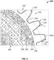
- the inner tooth core 220 includes an inner perimeter 224 and opposite outer perimeter 226 and has a core thickness Tc defined between the inner perimeter 224 and the outer perimeter 226.
- the core thickness Tc is about 2 times to about 3 times an addendum Ad ( FIG. 5 ) of the lightweight gear 200 to ensure that the teeth 204 remain coupled to the lattice structure 206 during operation of the lightweight gear 200.
- the core thickness Tc is greater than 2 times the addendum Ad.
- the addendum Ad is a distance between a pitch circle PC of the lightweight gear 200 and a tip 204a of the tooth 204.
- the inner perimeter 224 includes a plurality of spaced apart projections 228.
- Each of the projections 228 interlock with the lattice structure 206 to couple the inner tooth core 220 to the lattice structure 206.
- the projections 228 also inhibit the teeth 204 from rotating relative to the lattice structure 206.
- at least one projection 228 is provided between every two teeth 204 to avoid shearing near an interface of the lattice structure 206 and the inner tooth core 220.
- each of the projections 228 is spaced apart by a distance Dp1, which is based on a predetermined gear ratio between two mating lightweight gears 200 of the gear train 104.
- Each of the projections 228 generally extends into the lattice structure 206 by a depth Dp2, which is about 3 millimeters (mm) to about 4 millimeters (mm) and about 1.5 times to about 2 times a lattice cell size of the lattice structure 206 in a fifth density zone 258.
- the lattice cell size of the lattice structure 206 in the fifth density zone 258 is about 2 millimeters (mm).
- the depth Dp2 is up to a maximum of two times the addendum Ad.
- each of the projections 228 extends axially from proximate the first gear side 207 to the second gear side 208.
- Each of the projections 228 also extend radially inward toward the hub 202 for coupling to the lattice structure 206.
- the projections 228 generally increase the load transfer capability of the lightweight gear 200.
- the projections 228 are recessed slightly relative to the first gear side 207, however, in other embodiments, the projections 228 may extend from the first gear side 207 to the second gear side 208.
- the outer perimeter 226 of the inner tooth core 220 defines a plurality of core teeth 230.
- the core teeth 230 are spaced apart about the perimeter of the inner tooth core 220 by a distance Dct, which is based on the predetermined gear ratio for the lightweight gear 200 in the gear train 104.
- the distance Dct is different and greater than the distance Dp1, which results in at least one of the projections 228 that is not radially aligned with a respective at least one of the core teeth 230.
- a portion of the projections 228 are misaligned with a portion of the core teeth 230.
- each of the core teeth 230 extend axially from the first gear side 207 to the second gear side 208.
- Each of the core teeth 230 also extend radially outward and away from the inner tooth core 220.
- the core teeth 230 have a shape that accommodates the outer tooth liner 222 to form the teeth 204.
- the outer tooth liner 222 is coupled to the outer perimeter 226 of the inner tooth core 220 so as to define the outer perimeter of the lightweight gear 200.
- the outer tooth liner 222 covers each of the core teeth 230 and forms the contact surface for each of the teeth 204.
- the outer tooth liner 222 is composed of a metal or metal alloy, and in one example is composed of hardened 17CrNiMo6, hardened 18CrNiMo7-6, 20MoCr4, or 20MnCr5.
- the outer tooth liner 222 and the hub 202 are composed of different metals or metal alloys.
- the outer tooth liner 222 is coupled to the inner tooth core 220 via interference fit and/or adhesives.
- the use of the outer tooth liner 222 provides the lightweight gear 200 with increased hardness and surface stress when compared to the use of a polymer-based material for the contact surface for the teeth 204.
- the outer tooth liner 222 has a hardness of about 50 HRC on the Hardness Rockwell C scale.
- the outer tooth liner 222 is heat treated to harden the outer tooth liner 222 through a thickness T of the outer tooth liner 222.
- the thickness T is greater than about 0.25 to about 4 times a module of the lightweight gear 200.
- the module of the lightweight gear 200 is the size of one of the teeth 204, and in this example, the module of the lightweight gear 200 is about 5 millimeters (mm) when a pitch circle diameter PD ( FIG. 3 ) of the lightweight gear 200 is about 120 millimeters (mm) and the lightweight gear 200 has about 24 teeth.
- the outer tooth liner 222 improves a backlash associated with the lightweight gear 200, which also reduces noise associated with the lightweight gear 200 during operation.
- the backlash between two lightweight gears 200 is calculated as the backlash between two gears having a pitch circle defined by the outer perimeter 226 minus two times the thickness T of the outer tooth liner 222.
- each tooth 204 of the teeth 204 is composed of the core tooth 230 and a portion of the outer tooth liner 222.
- the teeth 204 engage with a corresponding gear of the gear train 104 ( FIG. 1 ), such as another lightweight gear 200, to enable the lightweight gear 200 to be driven or to drive the other lightweight gear 200.
- the teeth 204 may have any desired characteristic to enable the teeth 204 and the lightweight gear 200 to meshingly engage with another gear of the gear train 104.
- the teeth 204 comprise a plurality of spur gear teeth, however, the teeth 204 may comprise gear teeth of any shape, including, but not limited to, helical, bevel, spiral bevel, hypoid, etc.
- the teeth 204 are coupled to the hub 202 via the lattice structure 206.
- the lattice structure 206 is composed of a metal or metal alloy, including, but not limited to, Cress316l, Ferrium C64 gear steel, and C64 steel.
- the lattice structure 206 is integrally formed, one-piece or monolithic via additive manufacturing, such as direct metal laser sintering (DMLS), for example.
- DMLS direct metal laser sintering
- the lattice structure 206 is composed of a material that is different than the material of the hub 202 and the outer tooth liner 222 to reduce weight and cost associated with the lightweight gear 200.
- the lattice structure 206 has a density that varies based on an operating condition of the lightweight gear 200.
- the density varies radially based on a shear stress or load distribution experienced by the lightweight gear 200 such that a density of the lattice is nonuniform in the radial direction.
- the density of the lattice structure 206 is substantially constant axially, or in a direction along the central axis CA, and varies radially or in a direction along a radial axis RA.
- the radial axis RA is perpendicular to the central axis CA.
- the lattice structure 206 includes five density zones: a first density zone 250, a second density zone 252, a third density zone 254, a fourth density zone 256 and the fifth density zone 258.
- Each of the first density zone 250, the second density zone 252, the third density zone 254, the fourth density zone 256 and the fifth density zone 258 has a different density of cells in associated zone of the lattice structure 206 based on the shear stress experienced during the operation of the lightweight gear 200.
- the first density zone 250 is coupled to the hub 202.
- the lattice structure 206 may be integrally formed with the hub 202, or an inner perimeter of the first density zone 250 may be fixedly coupled to the hub 202 via welding, for example.
- the first density zone 250 has a density of about 0.7 times to about 0.9 times a density of a fully solid metal or metal alloy structure. Stated another way, the lattice structure 206 in the first density zone 250 has a density that is about 70% to about 90% of the density of a solid metal or metal alloy structure.
- the first density zone 250 has the greatest density or is the densest portion of the lattice structure 206 due to shear stress experienced at the hub 202 during operation of the lightweight gear 200.
- a size of the lattice is smaller, which enables a high concentration of the lattice within the first density zone 250.
- a cell size of the lattice structure 206 in the first density zone 250 is about 2 millimeters (mm).
- the first density zone 250 extends for a length L1, which is radially about 7.5 millimeters (mm) to about 13 millimeters (mm) in the example of the lightweight gear 200 having a radius Lr of the lattice structure 206 of about 50 millimeters (mm). In this example, the first density zone 250 extends for about 20% of the radius Lr of the lattice structure 206.
- a relative density of the first density zone 250 is about 5.55 grams per cubic centimeters (g/cm 3 ) to about 7.13 grams per cubic centimeters (g/cm 3 ).
- the relative density is calculated by multiplying the density of the material by a volume fraction occupied by the lattice structure 206 in the first density zone 250 so that void space is not included in the density calculation.
- the second density zone 252 is coupled or integrally formed between the first density zone 250 and the third density zone 254.
- the second density zone 252 has a density of about 0.65 times to about 0.75 times the density of the fully solid metal or metal alloy structure.
- the lattice structure 206 in the second density zone 252 has a density that is about 65% to about 75% of the density of the solid metal or metal alloy structure.
- the second density zone 252 has a density that is less than the first density zone 250 and greater than the third density zone 254.
- a size of the lattice is larger, which enables a lower concentration of the lattice within the second density zone 252 when compared to the first density zone 250.
- a cell size of the lattice structure 206 in the second density zone 252 is about 3 millimeters (mm) to about 4 millimeters (mm).
- the second density zone 252 extends for a length L2, which is about 7 millimeters (mm) to about 12.5 millimeters (mm). In this example, the second density zone 252 extends for about 18% of the radius Lr of the lattice structure 206.
- the third density zone 254 is coupled or integrally formed between the second density zone 252 and the fourth density zone 256.
- the third density zone 254 has a density of about 0.4 times to about 0.65 times the density of the fully solid metal or metal alloy structure.
- the lattice structure 206 in the third density zone 254 has a density that is about 40% to about 65% of the density of the solid metal or metal alloy structure.
- the third density zone 254 has a density that is less than each of the first density zone 250, the second density zone 252, the fourth density zone 256 and the fifth density zone 258.
- the third density zone 254 is the least dense portion of the lattice structure 206 as the third density zone 254 generally experiences the least amount of shear stress or load.
- a size of the lattice is larger, which results in a low concentration of the lattice within the third density zone 254.
- a cell size of the lattice structure 206 in the third density zone 254 is about 4 millimeters (mm) to about 6 millimeters (mm).
- the third density zone 254 extends for a length L3, which is about 9.5 millimeters (mm) to about 15 millimeters (mm). In this example, the third density zone 254 extends for about 24% of the radius Lr of the lattice structure 206.
- the fourth density zone 256 is coupled or integrally formed between the third density zone 254 and the fifth density zone 258.
- the fourth density zone 256 has a density of about 0.6 times to about 0.75 times the density of the fully solid metal or metal alloy structure. Stated another way, the lattice structure 206 in the fourth density zone 256 has a density that is about 60% to about 75% of the density of the solid metal or metal alloy structure.
- the fourth density zone 256 has a density that is less than each of the first density zone 250, the second density zone 252 and the fifth density zone 258. The density of the fourth density zone 256 is greater than the density of the third density zone 254.
- a size of the lattice is smaller than the size of the lattice in the third density zone 254, which results in a larger concentration of the lattice within the fourth density zone 256.
- a cell size of the lattice structure 206 in the fourth density zone 256 is about 3 millimeters (mm) to about 4 millimeters (mm).
- the fourth density zone 256 extends for a length L4, which is about 7 millimeters (mm) to about 12.5 millimeters (mm). In this example, the fourth density zone 256 extends for about 18% of the radius Lr of the lattice structure 206.
- the fifth density zone 258 is coupled or integrally formed with the fourth density zone 256.
- the fifth density zone 258 has a density of about 0.70 times to about 0.80 times the density of the fully solid metal or metal alloy structure. Stated another way, the lattice structure 206 in the fifth density zone 258 has a density that is about 70% to about 80% of the density of the solid metal or metal alloy structure.
- the fifth density zone 258 has a density that is greater than each of the second density zone 252, the third density zone 254 and the fourth density zone 256.
- the density of the fifth density zone 258 is less than the density of the first density zone 250.
- the density of the fifth density zone 258 is predetermined based on the amount of shear stress or load received by the teeth 204.
- a size of the lattice is greater than the size of the lattice in the first density zone 250, which results in a larger concentration of the lattice within the fifth density zone 258.
- the fifth density zone 258 has cells that are about 2 millimeters (mm) in size.
- the fifth density zone 258 extends for a length L5, which is about 7.5 millimeters (mm) to about 13 millimeters (mm). In this example, the fifth density zone 258 extends for about 20% of a radius Lr of the lattice structure 206.
- the fifth density zone 258 also defines a plurality of channels 260 that extend axially about a perimeter 258a of the fifth density zone 258.
- Each channel 260 receives a respective one of the projections 228 to couple the tooth ring 203 including the teeth 204 to the lattice structure 206 at the fifth density zone 258.
- the tooth ring 203 may be coupled to the lattice structure 206 by injection molding the inner tooth core 220 about the perimeter 258a of the fifth density zone 258 and the resulting structure may not include defined projections 228 and channels 260 as shown herein.
- the first density zone 250 experiences a stress of about 128 Newtons per millimeter squared (N/mm 2 ); the second density zone 252 experiences a stress of about 110 Newtons per millimeter squared (N/mm 2 ); the third density zone 254 experiences a stress of about 74 Newtons per millimeter squared (N/mm 2 ); the fourth density zone 256 experiences a stress of about 105 Newtons per millimeter squared (N/mm 2 ); and the fifth density zone 258 experiences a stress of about 120 Newtons per millimeter squared (N/mm 2 ).
- the lattice structure 206 is the densest at or proximate the hub 202, transitions to less dense between the hub 202 and about 50% of the radius Lr of the lattice structure 206, and transitions from less dense to denser at or proximate the teeth 204.
- a weight of the lightweight gear 200 is reduced as less material is used in the lower density zones while maintaining the performance of the lightweight gear 200, which provides a weight savings.
- each of the density zones 250-258 is composed of a plurality of cells, which replicate to form the lattice within the particular density zone 250-258.
- the shape of the cell in a respective density zone 250-258 includes, but is not limited to, body-centered cubic (BCC), body-centered cubic with Z-struts (BCCZ), Octahedroid, Octahedroid with struts, triply periodic minimal surfaces (TPMS), and dodecahedron.
- BCC body-centered cubic
- BCCZ body-centered cubic with Z-struts
- TPMS triply periodic minimal surfaces
- dodecahedron the shape of the cells of each of the density zones 250-258 may be different.
- the first density zone 250 and the fifth density zone 258 may include cells with more crosslinking struts, such as dodecahedron cells due to the higher stress experienced by the first density zone 250 and the fifth density zone 258.
- the third density zone 254, which experiences lower stress and is less dense may include body-centered cubic cells or Octahedroid cells with struts.
- the second density zone 252 and the fourth density zone 256 may each include triply periodic minimal surfaces (TPMS) cells.
- TPMS triply periodic minimal surfaces
- the density zones 250-258 may have cells with the same shape. It should be noted that the dimensions and values provided herein are merely examples, and are not intended to limit the scope of the present disclosure.
- the lightweight gear 200 is shown with a polymer-based coating 300.
- the lattice structure 206 of the lightweight gear 200 of FIG. 6 is injection molded with the polymer-based coating 300 to provide additional strength to the lightweight gear 200.
- the polymer-based material of the polymer-based coating 300 includes, but is not limited to, PA-Nylon 6/6 (30% glass fiber), PA-Nylon 6,6 (30% carbon fiber), Acetal copolymer (such as DURACON ® POM commercially available from Polyplastics Co., Ltd. of Tokyo, Japan), and MC (Monocast) Nylon.
- the polymer-based coating 300 is injection molded through the lattice structure 206 to extend axially from the first gear side 207 to the second gear side 208.
- the polymer-based coating 300 is injected into the first gear side 207 or the second gear side 208 and flows through the lattice structure 206 to the opposing side; however, in other examples, the polymer-based coating 300 may be injected into both the first gear side 207 and the second gear side 208.
- other techniques such as spray coating, void filling, etc. may be employed to couple the polymer-based coating 300 to the lightweight gear 200.
- the lightweight gear 200 may be configured differently to engage with another gear of the gear train 104 ( FIG. 1 ).
- a lightweight gear 400 is shown.
- the lightweight gear 400 includes components that are the same or similar to components of the lightweight gear 200 discussed with regard to FIGS. 1-6 , the same reference numerals will be used to denote the same or similar components.
- the lightweight gear 400 includes a hub 402 and a tooth ring 403 including a plurality of teeth 404.
- the hub 402 is interconnected to the tooth ring 403 by the core or lattice structure 206.
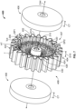
- the lightweight gear 400 includes at least one or a pair of composite panels 406, and the lattice structure 206 is sandwiched between the composite panels 406.
- the lightweight gear 400 has a first gear side 407 opposite a second gear side 408.
- the hub 402 defines the central opening 210 of the lightweight gear 400 and enables the lightweight gear 400 to be coupled to a shaft, such as the shaft 106, ( FIG. 1 ) to rotate the shaft 106.
- the hub 402 is cylindrical, and is solid along its diameter.
- the hub 402 is composed of a metal or metal alloy, including, but not limited to hardened 42CrMo4 and Cres316L.
- the hub 402 may be formed via casting, additive manufacturing, etc.
- the hub 402 defines a central axis CA4 for the lightweight gear 400, and forms an inner diameter D 14 of the lightweight gear 400.
- the hub 402 extends for a distance D15 beyond the lattice structure 206 to pass through a respective one of the composite panels 406.
- Each of the composite panels 406 has an opening 406a, and the hub 402 extends through the opening 406a.
- the distance D15 is sized to enable the composite panels 406 to be positioned adjacent to and in contact with the lattice structure 206 without extending outwardly from the respective first gear side 407 or the second gear side 408.
- the distance D15 is about 2.15 millimeters (mm) to about 3.2 millimeters (mm).
- the tooth ring 403 including the teeth 404 is defined about an outer circumference of the lightweight gear 400.
- the tooth ring 403 is defined by an inner tooth core 420 and an outer tooth liner 422, which cooperate to form or define the teeth 404.
- the tooth ring 403 including the teeth 404 extends about an outer circumference of the lattice structure 206 to define the outer circumference of the lightweight gear 400.
- the inner tooth core 420 and the outer tooth liner 422 comprise the tooth ring 403.
- the teeth 404 also extend the distance D15 beyond the lattice structure 206 on either side of the lattice structure 206 to accommodate the composite panels 406.
- the inner tooth core 420 couples or interconnects the lattice structure 206 and the composite panels 406 with the outer tooth liner 222.
- the inner tooth core 420 is composed of a polymer-based material, including, but not limited to PA-Nylon 6/6 (30% glass fiber), PA-Nylon 6,6 (30% carbon fiber), Acetal copolymer (such as DURACON ® POM commercially available from Polyplastics Co., Ltd. of Tokyo, Japan), and MC (Monocast) Nylon.
- PA-Nylon 6/6 (30% glass fiber
- PA-Nylon 6,6 (30% carbon fiber
- Acetal copolymer such as DURACON ® POM commercially available from Polyplastics Co., Ltd. of Tokyo, Japan
- MC Monocast
- the inner tooth core 420 includes an inner perimeter 424 and opposite outer perimeter 426, and has a core thickness Tc4 defined between the inner perimeter 424 and the outer perimeter 426.
- the core thickness Tc4 is about 0.9 to about 1 times a height Ht of the teeth 404 to ensure that the teeth 404 remain coupled to the lattice structure 206 during operation of the lightweight gear 400.
- the core thickness Tc4 is about 10 millimeters (mm) to about 11 millimeters (mm).
- the inner perimeter 424 includes a plurality of spaced apart projections 428. Each of the projections 428 interlock with the lattice structure 206 and the composite panels 406 to couple the inner tooth core 420 to the lattice structure 206.
- the projections 428 also inhibit the teeth 404 from rotating relative to the lattice structure 206.
- each of the projections 428 is spaced apart by the distance Dp1.
- Each of the projections 428 generally extends into the lattice structure 206 by the depth Dp2.
- Each of the projections 428 extends axially from the first gear side 407 to the second gear side 408, and in this example, each of the projections 428 extend the distance D15 beyond the lattice structure 206 to enable the composite panels 406 to be coupled to the lattice structure 206.
- Each of the projections 428 also extend radially inward toward the hub 402 for coupling to the lattice structure 206 and the composite panels 406.
- the inner tooth core 420 may not include the plurality of projections 428, but rather, may be a cylinder that is coupled or formed onto the lattice structure 206 if the stress experienced by the lightweight gear 200 is low.
- the outer perimeter 426 of the inner tooth core 420 defines a plurality of core teeth 430.
- the core teeth 430 are spaced apart about the perimeter of the inner tooth core 420 by the distance Dct. At least one of the projections 428 is not radially aligned with at least one of the core teeth 430. Stated another way, a portion of the projections 428 are misaligned with a portion of the core teeth 430. In one example, there is a different and greater number of projections 428 than the core teeth 430. This ensures that the teeth 404 remain coupled to the lattice structure 206 during operation of the lightweight gear 400.
- Each of the core teeth 430 extend axially from the first gear side 407 to the second gear side 408.
- Each of the core teeth 430 also extend radially outward and away from the inner tooth core 420.
- the core teeth 430 have a shape that accommodates the outer tooth liner 422 to form the teeth 404.
- the outer tooth liner 422 is coupled to the outer perimeter 426 of the inner tooth core 420 so as to define the outer perimeter of the lightweight gear 400.
- the outer tooth liner 422 covers each of the core teeth 430 and forms the contact surface for each of the teeth 404.
- the outer tooth liner 422 is composed of a metal or metal alloy, and in one example is composed of hardened 20MoCr4 or 20MnCr5. In one example, the outer tooth liner 422 and the hub 402 are composed of a different metal or metal alloy.
- the outer tooth liner 422 is coupled to the inner tooth core 420 via an interference fit and/or adhesives.
- the use of the outer tooth liner 422 provides the lightweight gear 400 with increased hardness and surface stress over the use of a polymer-based material for the contact surface for the teeth 404.
- the outer tooth liner 422 has a hardness of about 50 HRC on the Hardness Rockwell C scale.
- the outer tooth liner 422 is heat treated to harden the outer tooth liner 422 through the thickness T of the outer tooth liner 422.
- the outer tooth liner 422 improves a backlash associated with the lightweight gear 400, which also reduces noise associated with the lightweight gear 400 during operation.
- the backlash between two lightweight gears 400 is calculated as the backlash between two gears having a pitch circle defined by the outer perimeter 426 minus two times the thickness T of the outer tooth liner 422.
- each tooth 404 of the teeth 404 is composed of the core tooth 430 and a portion of the outer tooth liner 422.
- the teeth 404 engage with a corresponding gear of the gear train 104 ( FIG. 1 ), such as another lightweight gear 200, 400 to enable the lightweight gear 400 to enable the lightweight gear 400 to be driven or to drive the other lightweight gear 200, 400.
- the teeth 404 may have any desired characteristic to enable the teeth 404 and the lightweight gear 400 to meshingly engage with another gear of the gear train 104.
- the teeth 404 comprise a plurality of spur gear teeth, however, the teeth 404 may comprise gear teeth of any shape, including, but not limited to, helical, bevel, spiral bevel, hypoid, etc.
- the tooth ring 403 is coupled to the hub 402 via the lattice structure 206.
- the composite panels 406 are coupled to opposed sides of the lattice structure 206 such that the first gear side 407 and the second gear side 408 are defined by a respective one of the composite panels 406.
- Each of the composite panels 406 is composed of a polymer-based material, including, but not limited to carbon fiber reinforced polymer-based material, glass fiber reinforced composite, aramid fiber reinforced polymer, and graphite prepreg material.
- the composite panels 406 are each formed via composite ply lay-up and coupled to the lattice structure 206 after the additive manufacture of the lattice structure 206.
- each of the composite panels 406 is formed to have a plurality of layers to result in a thickness CT, which is substantially the same as the distance D15 to provide a uniform appearance on the first gear side 407 and the second gear side 408.
- the composite panels 406 are composed of about 6 to about 9 sheets of prepreg material, and a single sheet of prepreg is about 3.5 millimeters (mm).
- the lattice structure 206 is additively manufactured onto the hub 202, 402.
- the inner tooth core 220, 420 is coupled to or formed on the lattice structure 206 such that the projections 228, 428 engage with the channels 260 of the fifth density zone 258.
- the outer tooth liner 222, 422 is coupled to the inner tooth core 220, 420 to define the outer perimeter of the lightweight gear 200, 400.
- the polymer-based coating 300 is applied, via injection molding, for example, to the first gear side 207 and/or the second gear side 208 so as to infiltrate the lattice structure 206.
- the composite panels 406 are each formed and coupled to the lattice structure 206 to have the thickness CT that results in a uniform surface for the first gear side 407 and the second gear side 408, respectively.
- the lightweight gear 200, 400 may be coupled to the shaft 106 via the hub 202, 402 and installed into the gear box 102 such that the teeth 204 engage with another gear of the gear train 104.
- the lightweight gear 200, 400 cooperates with the gear train 104 to generate torque to start the engine 112 or to drive the rotor 114.
- the lattice structure 206 of the lightweight gear 200, 400 reduces a weight of the lightweight gear 200, 400 by providing the varying density zones 250-258 in the radial direction.
- the outer tooth liner 222, 422 ensures that the lightweight gear 200 has sufficient hardness, and the inner tooth core 220, 420 assists in reducing noise during the operation of the lightweight gear 200, 400.
Landscapes
- Engineering & Computer Science (AREA)
- General Engineering & Computer Science (AREA)
- Mechanical Engineering (AREA)
- Physics & Mathematics (AREA)
- Electromagnetism (AREA)
- Thermal Sciences (AREA)
- Gears, Cams (AREA)
Abstract
Description
- This application claims priority to
Indian Provisional Patent Application No. 202211029954, filed May 25, 2022 - The present disclosure generally relates to gears, and more particularly relates to a lightweight gear for a vehicle.
- Gears may be used in various mechanical systems to transmit torque and speed. Gears may be employed in a variety of different applications, including vehicle applications, for example. Generally, gears are generally composed of a single material. For example, gears may be composed of a solid metal or metal alloy to provide wear resistance. The use of a solid metal or metal alloy gear, however, results in the gear having a high weight. In addition, a solid metal or metal alloy gear may generate undesirable noise when in operation.
- Accordingly, it is desirable to provide a lightweight gear, which also reduces noise while in operation. Furthermore, other desirable features and characteristics of the present invention will become apparent from the subsequent detailed description and the appended claims, taken in conjunction with the accompanying drawings and the foregoing technical field and background.
- According to various embodiments, provided is a lightweight gear. The lightweight gear includes a hub, and a tooth ring defining a plurality of gear teeth. The tooth ring includes an inner core composed of a polymer-based material that is coupled to the lattice structure. The lightweight gear includes a lattice structure interconnecting the hub and the tooth ring. The lattice structure has a density that varies radially based on an operating condition of the lightweight gear and the lattice structure is composed of a metal or a metal alloy.
- The tooth ring includes an outer liner coupled to the inner core that defines contact surfaces for the plurality of gear teeth. The outer liner is composed of a second metal or a second metal alloy. The inner core includes a plurality of projections that extend radially inward to couple to the lattice structure. The inner core includes a plurality of core teeth opposite the plurality of projections, and the outer liner is coupled to the plurality of core teeth to define the plurality of gear teeth. A portion of the plurality of core teeth are radially misaligned with a portion of the plurality of projections. The lattice structure defines a plurality of channels about an outer perimeter of the lattice structure, and each channel of the plurality of channels extends axially and is configured to receive a projection of the plurality of projections. The lightweight gear includes a polymer-based coating coupled to the lattice structure. The lightweight gear includes at least one panel of polymer-based material coupled to at least one side of the lattice structure. The operating condition of the lightweight gear is a shear stress. The lattice structure has a first zone with a first density at the hub that is different and greater than a zone density of a zone of the lattice structure at the tooth ring. The lattice structure has a second zone with a second density between the first zone and the zone, and the second density is less than the first density and the zone density. The lattice structure has a third zone with a third density between the second zone and the zone, and the third density is less than the second density. The lattice structure includes a fourth zone with a fourth density between the third zone and the zone, and the fourth density is greater than the third density. A cell of the lattice structure in the third zone has a different shape than a cell of the lattice structure in the first zone.
- Also provided is a lightweight gear for a vehicle. The lightweight gear includes a hub composed of a first metal or metal alloy and a tooth ring including an inner core and an outer liner that cooperate to define a plurality of gear teeth. The inner core is composed of a polymer-based material that is coupled to a lattice structure and the outer liner is composed of a second metal or a second metal alloy. The lightweight gear includes the lattice structure interconnecting the hub and the inner core of the tooth ring. The lattice structure has a density that varies radially, with a first zone having a first density proximate the hub that is different and greater than a zone density of a zone of the lattice structure proximate the inner core. The lattice structure is composed of a metal or metal alloy.
- Between the first zone and the zone, the lattice structure has a second zone with a second density that is less than the first density and the zone density. The inner core includes a plurality of projections that extend radially inward to couple to the lattice structure and includes a plurality of core teeth opposite the plurality of projections. At least one of the plurality of projections is misaligned with at least one of the plurality of core teeth, and the outer liner is coupled to the plurality of core teeth to define the plurality of gear teeth. The includes a polymer-based coating coupled to the lattice structure. The lightweight gear includes at least one panel of polymer-based material coupled to at least one side of the lattice structure.
- The exemplary embodiments will hereinafter be described in conjunction with the following drawing figures, wherein like numerals denote like elements, and wherein:
-
FIG. 1 is a functional block diagram of a vehicle, which includes a lightweight gear in accordance with the various teachings of the present disclosure; -
FIG. 2 is a perspective view of the lightweight gear for use with the vehicle ofFIG. 1 in accordance with various embodiments; -
FIG. 3 is a side view of the lightweight gear ofFIG. 2 ; -
FIG. 4 is a cross-sectional view of the lightweight gear ofFIG. 2 , taken along line 4-4 ofFIG. 2 ; -
FIG. 5 is a detail view of the lightweight gear ofFIG. 3 , taken at 5 onFIG. 3 ; -
FIG. 6 is a side view of another exemplary lightweight gear for use with the vehicle ofFIG. 1 in accordance with various embodiments; and -
FIG. 7 is an exploded perspective view of another exemplary lightweight gear for use with the vehicle ofFIG. 1 in accordance with various embodiments. - The following detailed description is merely exemplary in nature and is not intended to limit the application and uses. Furthermore, there is no intention to be bound by any expressed or implied theory presented in the preceding technical field, background, brief summary or the following detailed description. In addition, those skilled in the art will appreciate that embodiments of the present disclosure may be practiced in conjunction with any type of device that would benefit from the lightweight gear described herein and the use of the lightweight gear in a vehicle is merely one exemplary embodiment according to the present disclosure. In addition, while the lightweight gear is described herein as being used with a vehicle, such as a bus, motorcycle, train, motor vehicle, marine vessel, aircraft, rotorcraft and the like, the various teachings of the present disclosure can be used with other stationary platforms. Further, it should be noted that many alternative or additional functional relationships or physical connections may be present in an embodiment of the present disclosure. In addition, while the figures shown herein depict an example with certain arrangements of elements, additional intervening elements, devices, features, or components may be present in an actual embodiment. It should also be understood that the drawings are merely illustrative and may not be drawn to scale.
- As used herein, the term "axial" refers to a direction that is generally parallel to or coincident with an axis of rotation, axis of symmetry, or centerline of a component or components. For example, in a cylinder or disc with a centerline and generally circular ends or opposing faces, the "axial" direction may refer to the direction that generally extends in parallel to the centerline between the opposite ends or faces. In certain instances, the term "axial" may be utilized with respect to components that are not cylindrical (or otherwise radially symmetric). For example, the "axial" direction for a rectangular housing containing a rotating shaft may be viewed as a direction that is generally parallel to or coincident with the rotational axis of the shaft. Furthermore, the term "radially" as used herein may refer to a direction or a relationship of components with respect to a line extending outward from a shared centerline, axis, or similar reference, for example in a plane of a cylinder or disc that is perpendicular to the centerline or axis. In certain instances, components may be viewed as "radially" aligned even though one or both of the components may not be cylindrical (or otherwise radially symmetric). Furthermore, the terms "axial" and "radial" (and any derivatives) may encompass directional relationships that are other than precisely aligned with (e.g., oblique to) the true axial and radial dimensions, provided the relationship is predominantly in the respective nominal axial or radial direction. As used herein, the term "substantially" denotes within 5% to account for manufacturing tolerances. Also, as used herein, the term "about" denotes within 5% to account for manufacturing tolerances.
- With reference to
FIG. 1 , a functional block diagram of components associated with avehicle 100, which in this example is a rotorcraft, is shown. In this example, thevehicle 100 includes at least onelightweight gear 200. It should be noted that while thelightweight gear 200 is described herein as being used with components associated with thevehicle 100, thelightweight gear 200 may be employed in various applications, and thus, the use of thelightweight gear 200 with thevehicle 100 is merely an example. In the example ofFIG. 1 , thelightweight gear 200 is associated with agear box 102 of thevehicle 100. Thegear box 102 includes at least one or more of thelightweight gear 200, which cooperate to form agear train 104 within thegear box 102. In one example, thegear train 104 of thegear box 102 transfers torque to ashaft 106. Thegear train 104 may drive theshaft 106, based on input received from anair starter 110 associated with thevehicle 100, for example, or thegear train 104 may be driven by anengine 112 of thevehicle 100 to supply torque to arotor 114 associated with thevehicle 100. Theair starter 110 is any air starter capable of converting air into mechanical torque, which is transferred via thegear train 104 to theshaft 106 to rotate or turn theengine 112 until theengine 112 reaches ignition speed. In another example, thegear train 104 of thegear box 102 may drive theshaft 106 based on input received from an electric motor or actuator associated with thevehicle 100. Theengine 112 is any engine for powering thevehicle 100, and in one example, is a gas turbine engine, such as a turboprop or turboshaft engine. During operation of theengine 112, theengine 112 drives theshaft 106, which in turn drives thegear train 104 to transmit torque to therotor 114. Therotor 114 is any rotor associated with thevehicle 100, including a main rotor or the tail rotor. As will be discussed, the use of thelightweight gear 200 in thegear box 102 reduces a weight associated with thegear box 102, and thus, the weight of thevehicle 100. The reduction in weight may result in an increased fuel economy for thevehicle 100. In addition, the use of thelightweight gear 200 also reduces a noise associated with the operation of thegear train 104 within thegear box 102. The use of thelightweight gear 200 also assists in dampening vibrations experienced by thegear box 102. - With reference to
FIG. 2 , a perspective view of thelightweight gear 200 is shown. Thelightweight gear 200 includes ahub 202 and atooth ring 203 including a plurality ofteeth 204. Thehub 202 is interconnected to thetooth ring 203 by a core orlattice structure 206. Thelightweight gear 200 also has afirst gear side 207 opposite asecond gear side 208. Thehub 202 defines acentral opening 210 of thelightweight gear 200 and enables thelightweight gear 200 to be coupled to a shaft 106 (FIG. 1 ) to rotate with theshaft 106. In certain examples, thecentral opening 210 may include a notch, key, splines or other feature to non-rotatably couple thelightweight gear 200 to the shaft. Thehub 202 is cylindrical, and is solid along its diameter. Thehub 202 is composed of a metal or metal alloy, including, but not limited to hardened 42CrMo4 and Cres316L. Thehub 202 may be formed via casting, additive manufacturing, etc. With reference toFIG. 3 , thehub 202 defines a central axis CA for thelightweight gear 200, and forms an inner diameter D1 of thelightweight gear 200. - The
tooth ring 203 including theteeth 204 is defined about an outer circumference of thelightweight gear 200. In this example, thetooth ring 203 is defined by an inner core orinner tooth core 220 and an outer liner orouter tooth liner 222, which cooperate to form or define theteeth 204. Thetooth ring 203 including theteeth 204 extends about an outer circumference of thelattice structure 206 to define the outer circumference of thelightweight gear 200. Thus, theinner tooth core 220 and theouter tooth liner 222 comprise thetooth ring 203. Theinner tooth core 220 couples or interconnects thelattice structure 206 with theouter tooth liner 222. In one example, theinner tooth core 220 is composed of a polymer-based material, including, but not limited to PA-Nylon 6/6 (30% glass fiber), PA-Nylon 6,6 (30% carbon fiber), Acetal copolymer (such as DURACON® POM commercially available from Polyplastics Co., Ltd. of Tokyo, Japan), and MC (Monocast) Nylon. By composing theinner tooth core 220 out of a polymer-based material, theinner tooth core 220 provides damping and reduces noise generated by the operation of thelightweight gear 200. Theinner tooth core 220 is coupled to thelattice structure 206 via injection molding, composite ply lay-up, etc. In one example, theinner tooth core 220 includes aninner perimeter 224 and oppositeouter perimeter 226 and has a core thickness Tc defined between theinner perimeter 224 and theouter perimeter 226. The core thickness Tc is about 2 times to about 3 times an addendum Ad (FIG. 5 ) of thelightweight gear 200 to ensure that theteeth 204 remain coupled to thelattice structure 206 during operation of thelightweight gear 200. Generally, the core thickness Tc is greater than 2 times the addendum Ad. With reference toFIG. 5 , the addendum Ad is a distance between a pitch circle PC of thelightweight gear 200 and atip 204a of thetooth 204. - With reference back to
FIG. 2 , theinner perimeter 224 includes a plurality of spaced apartprojections 228. Each of theprojections 228 interlock with thelattice structure 206 to couple theinner tooth core 220 to thelattice structure 206. Theprojections 228 also inhibit theteeth 204 from rotating relative to thelattice structure 206. Generally, at least oneprojection 228 is provided between every twoteeth 204 to avoid shearing near an interface of thelattice structure 206 and theinner tooth core 220. In this example, each of theprojections 228 is spaced apart by a distance Dp1, which is based on a predetermined gear ratio between two mating lightweight gears 200 of thegear train 104. Each of theprojections 228 generally extends into thelattice structure 206 by a depth Dp2, which is about 3 millimeters (mm) to about 4 millimeters (mm) and about 1.5 times to about 2 times a lattice cell size of thelattice structure 206 in afifth density zone 258. In this example, the lattice cell size of thelattice structure 206 in thefifth density zone 258 is about 2 millimeters (mm). Generally, the depth Dp2 is up to a maximum of two times the addendum Ad. As shown inFIG. 4 , each of theprojections 228 extends axially from proximate thefirst gear side 207 to thesecond gear side 208. Each of theprojections 228 also extend radially inward toward thehub 202 for coupling to thelattice structure 206. Theprojections 228 generally increase the load transfer capability of thelightweight gear 200. In this example, theprojections 228 are recessed slightly relative to thefirst gear side 207, however, in other embodiments, theprojections 228 may extend from thefirst gear side 207 to thesecond gear side 208. - With reference back to
FIG. 3 , theouter perimeter 226 of theinner tooth core 220 defines a plurality ofcore teeth 230. Thecore teeth 230 are spaced apart about the perimeter of theinner tooth core 220 by a distance Dct, which is based on the predetermined gear ratio for thelightweight gear 200 in thegear train 104. Generally, the distance Dct is different and greater than the distance Dp1, which results in at least one of theprojections 228 that is not radially aligned with a respective at least one of thecore teeth 230. Stated another way, a portion of theprojections 228 are misaligned with a portion of thecore teeth 230. In one example, there is also a different and greater number ofprojections 228 than thecore teeth 230. This ensures that theteeth 204 remain coupled to thelattice structure 206 during operation of thelightweight gear 200. With reference toFIG. 4 , each of thecore teeth 230 extend axially from thefirst gear side 207 to thesecond gear side 208. Each of thecore teeth 230 also extend radially outward and away from theinner tooth core 220. Generally, thecore teeth 230 have a shape that accommodates theouter tooth liner 222 to form theteeth 204. - The
outer tooth liner 222 is coupled to theouter perimeter 226 of theinner tooth core 220 so as to define the outer perimeter of thelightweight gear 200. Theouter tooth liner 222 covers each of thecore teeth 230 and forms the contact surface for each of theteeth 204. Theouter tooth liner 222 is composed of a metal or metal alloy, and in one example is composed of hardened 17CrNiMo6, hardened 18CrNiMo7-6, 20MoCr4, or 20MnCr5. In one example, theouter tooth liner 222 and thehub 202 are composed of different metals or metal alloys. Theouter tooth liner 222 is coupled to theinner tooth core 220 via interference fit and/or adhesives. The use of theouter tooth liner 222 provides thelightweight gear 200 with increased hardness and surface stress when compared to the use of a polymer-based material for the contact surface for theteeth 204. Generally, theouter tooth liner 222 has a hardness of about 50 HRC on the Hardness Rockwell C scale. In this example, with reference toFIG. 5 , theouter tooth liner 222 is heat treated to harden theouter tooth liner 222 through a thickness T of theouter tooth liner 222. In one example, the thickness T is greater than about 0.25 to about 4 times a module of thelightweight gear 200. The module of thelightweight gear 200 is the size of one of theteeth 204, and in this example, the module of thelightweight gear 200 is about 5 millimeters (mm) when a pitch circle diameter PD (FIG. 3 ) of thelightweight gear 200 is about 120 millimeters (mm) and thelightweight gear 200 has about 24 teeth. In addition, theouter tooth liner 222 improves a backlash associated with thelightweight gear 200, which also reduces noise associated with thelightweight gear 200 during operation. In one example, the backlash between twolightweight gears 200 is calculated as the backlash between two gears having a pitch circle defined by theouter perimeter 226 minus two times the thickness T of theouter tooth liner 222. - Thus, in this example, each
tooth 204 of theteeth 204 is composed of thecore tooth 230 and a portion of theouter tooth liner 222. Theteeth 204 engage with a corresponding gear of the gear train 104 (FIG. 1 ), such as anotherlightweight gear 200, to enable thelightweight gear 200 to be driven or to drive the otherlightweight gear 200. Generally, theteeth 204 may have any desired characteristic to enable theteeth 204 and thelightweight gear 200 to meshingly engage with another gear of thegear train 104. In this example, theteeth 204 comprise a plurality of spur gear teeth, however, theteeth 204 may comprise gear teeth of any shape, including, but not limited to, helical, bevel, spiral bevel, hypoid, etc. - The
teeth 204 are coupled to thehub 202 via thelattice structure 206. In this example, thelattice structure 206 is composed of a metal or metal alloy, including, but not limited to, Cress316l, Ferrium C64 gear steel, and C64 steel. Thelattice structure 206 is integrally formed, one-piece or monolithic via additive manufacturing, such as direct metal laser sintering (DMLS), for example. Generally, thelattice structure 206 is composed of a material that is different than the material of thehub 202 and theouter tooth liner 222 to reduce weight and cost associated with thelightweight gear 200. Thelattice structure 206 has a density that varies based on an operating condition of thelightweight gear 200. For example, the density varies radially based on a shear stress or load distribution experienced by thelightweight gear 200 such that a density of the lattice is nonuniform in the radial direction. In this example, with brief reference toFIG. 3 , the density of thelattice structure 206 is substantially constant axially, or in a direction along the central axis CA, and varies radially or in a direction along a radial axis RA. The radial axis RA is perpendicular to the central axis CA. With reference back toFIG. 2 , in this example, thelattice structure 206 includes five density zones: afirst density zone 250, asecond density zone 252, athird density zone 254, afourth density zone 256 and thefifth density zone 258. Each of thefirst density zone 250, thesecond density zone 252, thethird density zone 254, thefourth density zone 256 and thefifth density zone 258 has a different density of cells in associated zone of thelattice structure 206 based on the shear stress experienced during the operation of thelightweight gear 200. - With reference to
FIG. 4 , thefirst density zone 250 is coupled to thehub 202. Thelattice structure 206 may be integrally formed with thehub 202, or an inner perimeter of thefirst density zone 250 may be fixedly coupled to thehub 202 via welding, for example. Thefirst density zone 250 has a density of about 0.7 times to about 0.9 times a density of a fully solid metal or metal alloy structure. Stated another way, thelattice structure 206 in thefirst density zone 250 has a density that is about 70% to about 90% of the density of a solid metal or metal alloy structure. Generally, thefirst density zone 250 has the greatest density or is the densest portion of thelattice structure 206 due to shear stress experienced at thehub 202 during operation of thelightweight gear 200. In thefirst density zone 250, a size of the lattice is smaller, which enables a high concentration of the lattice within thefirst density zone 250. For example, a cell size of thelattice structure 206 in thefirst density zone 250 is about 2 millimeters (mm). Thefirst density zone 250 extends for a length L1, which is radially about 7.5 millimeters (mm) to about 13 millimeters (mm) in the example of thelightweight gear 200 having a radius Lr of thelattice structure 206 of about 50 millimeters (mm). In this example, thefirst density zone 250 extends for about 20% of the radius Lr of thelattice structure 206. In the example of thelightweight gear 200 composed of Cress316l, a relative density of thefirst density zone 250 is about 5.55 grams per cubic centimeters (g/cm3) to about 7.13 grams per cubic centimeters (g/cm3). Generally, the relative density is calculated by multiplying the density of the material by a volume fraction occupied by thelattice structure 206 in thefirst density zone 250 so that void space is not included in the density calculation. - The
second density zone 252 is coupled or integrally formed between thefirst density zone 250 and thethird density zone 254. Thesecond density zone 252 has a density of about 0.65 times to about 0.75 times the density of the fully solid metal or metal alloy structure. Stated another way, thelattice structure 206 in thesecond density zone 252 has a density that is about 65% to about 75% of the density of the solid metal or metal alloy structure. Generally, thesecond density zone 252 has a density that is less than thefirst density zone 250 and greater than thethird density zone 254. In thesecond density zone 252, a size of the lattice is larger, which enables a lower concentration of the lattice within thesecond density zone 252 when compared to thefirst density zone 250. For example, a cell size of thelattice structure 206 in thesecond density zone 252 is about 3 millimeters (mm) to about 4 millimeters (mm). Thesecond density zone 252 extends for a length L2, which is about 7 millimeters (mm) to about 12.5 millimeters (mm). In this example, thesecond density zone 252 extends for about 18% of the radius Lr of thelattice structure 206. - The
third density zone 254 is coupled or integrally formed between thesecond density zone 252 and thefourth density zone 256. Thethird density zone 254 has a density of about 0.4 times to about 0.65 times the density of the fully solid metal or metal alloy structure. Stated another way, thelattice structure 206 in thethird density zone 254 has a density that is about 40% to about 65% of the density of the solid metal or metal alloy structure. Generally, thethird density zone 254 has a density that is less than each of thefirst density zone 250, thesecond density zone 252, thefourth density zone 256 and thefifth density zone 258. Thus, thethird density zone 254 is the least dense portion of thelattice structure 206 as thethird density zone 254 generally experiences the least amount of shear stress or load. In thethird density zone 254, a size of the lattice is larger, which results in a low concentration of the lattice within thethird density zone 254. For example, a cell size of thelattice structure 206 in thethird density zone 254 is about 4 millimeters (mm) to about 6 millimeters (mm). Thethird density zone 254 extends for a length L3, which is about 9.5 millimeters (mm) to about 15 millimeters (mm). In this example, thethird density zone 254 extends for about 24% of the radius Lr of thelattice structure 206. - The
fourth density zone 256 is coupled or integrally formed between thethird density zone 254 and thefifth density zone 258. Thefourth density zone 256 has a density of about 0.6 times to about 0.75 times the density of the fully solid metal or metal alloy structure. Stated another way, thelattice structure 206 in thefourth density zone 256 has a density that is about 60% to about 75% of the density of the solid metal or metal alloy structure. Generally, thefourth density zone 256 has a density that is less than each of thefirst density zone 250, thesecond density zone 252 and thefifth density zone 258. The density of thefourth density zone 256 is greater than the density of thethird density zone 254. In thefourth density zone 256, a size of the lattice is smaller than the size of the lattice in thethird density zone 254, which results in a larger concentration of the lattice within thefourth density zone 256. For example, a cell size of thelattice structure 206 in thefourth density zone 256 is about 3 millimeters (mm) to about 4 millimeters (mm). Thefourth density zone 256 extends for a length L4, which is about 7 millimeters (mm) to about 12.5 millimeters (mm). In this example, thefourth density zone 256 extends for about 18% of the radius Lr of thelattice structure 206. - The
fifth density zone 258 is coupled or integrally formed with thefourth density zone 256. Thefifth density zone 258 has a density of about 0.70 times to about 0.80 times the density of the fully solid metal or metal alloy structure. Stated another way, thelattice structure 206 in thefifth density zone 258 has a density that is about 70% to about 80% of the density of the solid metal or metal alloy structure. Generally, thefifth density zone 258 has a density that is greater than each of thesecond density zone 252, thethird density zone 254 and thefourth density zone 256. The density of thefifth density zone 258 is less than the density of thefirst density zone 250. The density of thefifth density zone 258 is predetermined based on the amount of shear stress or load received by theteeth 204. In thefifth density zone 258, a size of the lattice is greater than the size of the lattice in thefirst density zone 250, which results in a larger concentration of the lattice within thefifth density zone 258. Thefifth density zone 258 has cells that are about 2 millimeters (mm) in size. Thefifth density zone 258 extends for a length L5, which is about 7.5 millimeters (mm) to about 13 millimeters (mm). In this example, thefifth density zone 258 extends for about 20% of a radius Lr of thelattice structure 206. With reference back toFIG. 3 , thefifth density zone 258 also defines a plurality ofchannels 260 that extend axially about aperimeter 258a of thefifth density zone 258. Eachchannel 260 receives a respective one of theprojections 228 to couple thetooth ring 203 including theteeth 204 to thelattice structure 206 at thefifth density zone 258. It should be noted that while thetooth ring 203 is described herein as including theprojections 228 and thefifth density zone 258 is described herein as including thechannels 260, thetooth ring 203 may be coupled to thelattice structure 206 by injection molding theinner tooth core 220 about theperimeter 258a of thefifth density zone 258 and the resulting structure may not include definedprojections 228 andchannels 260 as shown herein. - In the example of the
lightweight gear 200 having the pitch diameter PD (FIG. 3 ) of 120 millimeters (mm), thelattice structure 206 having the radius Lr of 50 millimeters (mm), thelattice structure 206 composed of Cress316l and theouter tooth liner 222 composed of hardened 17CrNiMo6, thefirst density zone 250 experiences a stress of about 128 Newtons per millimeter squared (N/mm2); thesecond density zone 252 experiences a stress of about 110 Newtons per millimeter squared (N/mm2); thethird density zone 254 experiences a stress of about 74 Newtons per millimeter squared (N/mm2); thefourth density zone 256 experiences a stress of about 105 Newtons per millimeter squared (N/mm2); and thefifth density zone 258 experiences a stress of about 120 Newtons per millimeter squared (N/mm2). - Thus, generally, the
lattice structure 206 is the densest at or proximate thehub 202, transitions to less dense between thehub 202 and about 50% of the radius Lr of thelattice structure 206, and transitions from less dense to denser at or proximate theteeth 204. By varying the density of the core orlattice structure 206 radially based on the shear stress and load distribution, a weight of thelightweight gear 200 is reduced as less material is used in the lower density zones while maintaining the performance of thelightweight gear 200, which provides a weight savings. Generally, each of the density zones 250-258 is composed of a plurality of cells, which replicate to form the lattice within the particular density zone 250-258. The shape of the cell in a respective density zone 250-258 includes, but is not limited to, body-centered cubic (BCC), body-centered cubic with Z-struts (BCCZ), Octahedroid, Octahedroid with struts, triply periodic minimal surfaces (TPMS), and dodecahedron. In certain instances, the shape of the cells of each of the density zones 250-258 may be different. For example, thefirst density zone 250 and thefifth density zone 258 may include cells with more crosslinking struts, such as dodecahedron cells due to the higher stress experienced by thefirst density zone 250 and thefifth density zone 258. Thethird density zone 254, which experiences lower stress and is less dense, may include body-centered cubic cells or Octahedroid cells with struts. Thesecond density zone 252 and thefourth density zone 256 may each include triply periodic minimal surfaces (TPMS) cells. In other examples, the density zones 250-258 may have cells with the same shape. It should be noted that the dimensions and values provided herein are merely examples, and are not intended to limit the scope of the present disclosure. - It should be noted that in other applications, it may be desirable to further strengthen the
lightweight gear 200. For example, with reference toFIG. 6 , thelightweight gear 200 is shown with a polymer-basedcoating 300. In this example, thelattice structure 206 of thelightweight gear 200 ofFIG. 6 is injection molded with the polymer-basedcoating 300 to provide additional strength to thelightweight gear 200. The polymer-based material of the polymer-basedcoating 300 includes, but is not limited to, PA-Nylon 6/6 (30% glass fiber), PA-Nylon 6,6 (30% carbon fiber), Acetal copolymer (such as DURACON® POM commercially available from Polyplastics Co., Ltd. of Tokyo, Japan), and MC (Monocast) Nylon. Generally, the polymer-basedcoating 300 is injection molded through thelattice structure 206 to extend axially from thefirst gear side 207 to thesecond gear side 208. In one example, the polymer-basedcoating 300 is injected into thefirst gear side 207 or thesecond gear side 208 and flows through thelattice structure 206 to the opposing side; however, in other examples, the polymer-basedcoating 300 may be injected into both thefirst gear side 207 and thesecond gear side 208. It should be noted that other techniques, such as spray coating, void filling, etc. may be employed to couple the polymer-basedcoating 300 to thelightweight gear 200. - It should be noted that in other embodiments, the
lightweight gear 200 may be configured differently to engage with another gear of the gear train 104 (FIG. 1 ). For example, with reference toFIG. 7 , alightweight gear 400 is shown. As thelightweight gear 400 includes components that are the same or similar to components of thelightweight gear 200 discussed with regard toFIGS. 1-6 , the same reference numerals will be used to denote the same or similar components. In this example, thelightweight gear 400 includes ahub 402 and a tooth ring 403 including a plurality ofteeth 404. Thehub 402 is interconnected to the tooth ring 403 by the core orlattice structure 206. In this example, thelightweight gear 400 includes at least one or a pair ofcomposite panels 406, and thelattice structure 206 is sandwiched between thecomposite panels 406. Thelightweight gear 400 has afirst gear side 407 opposite asecond gear side 408. Thehub 402 defines thecentral opening 210 of thelightweight gear 400 and enables thelightweight gear 400 to be coupled to a shaft, such as theshaft 106, (FIG. 1 ) to rotate theshaft 106. Thehub 402 is cylindrical, and is solid along its diameter. Thehub 402 is composed of a metal or metal alloy, including, but not limited to hardened 42CrMo4 and Cres316L. Thehub 402 may be formed via casting, additive manufacturing, etc. Thehub 402 defines a central axis CA4 for thelightweight gear 400, and forms an inner diameter D 14 of thelightweight gear 400. In this example, thehub 402 extends for a distance D15 beyond thelattice structure 206 to pass through a respective one of thecomposite panels 406. Each of thecomposite panels 406 has an opening 406a, and thehub 402 extends through the opening 406a. Generally, the distance D15 is sized to enable thecomposite panels 406 to be positioned adjacent to and in contact with thelattice structure 206 without extending outwardly from the respectivefirst gear side 407 or thesecond gear side 408. In one example, the distance D15 is about 2.15 millimeters (mm) to about 3.2 millimeters (mm). - The tooth ring 403 including the
teeth 404 is defined about an outer circumference of thelightweight gear 400. In this example, the tooth ring 403 is defined by aninner tooth core 420 and anouter tooth liner 422, which cooperate to form or define theteeth 404. The tooth ring 403 including theteeth 404 extends about an outer circumference of thelattice structure 206 to define the outer circumference of thelightweight gear 400. Thus, theinner tooth core 420 and theouter tooth liner 422 comprise the tooth ring 403. Theteeth 404 also extend the distance D15 beyond thelattice structure 206 on either side of thelattice structure 206 to accommodate thecomposite panels 406. Theinner tooth core 420 couples or interconnects thelattice structure 206 and thecomposite panels 406 with theouter tooth liner 222. In one example, theinner tooth core 420 is composed of a polymer-based material, including, but not limited to PA-Nylon 6/6 (30% glass fiber), PA-Nylon 6,6 (30% carbon fiber), Acetal copolymer (such as DURACON® POM commercially available from Polyplastics Co., Ltd. of Tokyo, Japan), and MC (Monocast) Nylon. By composing theinner tooth core 420 out of a polymer-based material, theinner tooth core 420 provides damping and reduces noise generated by the operation of thelightweight gear 400. Theinner tooth core 420 is coupled to thelattice structure 206 via injection molding, composite ply lay-up, etc. - In one example, the
inner tooth core 420 includes aninner perimeter 424 and oppositeouter perimeter 426, and has a core thickness Tc4 defined between theinner perimeter 424 and theouter perimeter 426. The core thickness Tc4 is about 0.9 to about 1 times a height Ht of theteeth 404 to ensure that theteeth 404 remain coupled to thelattice structure 206 during operation of thelightweight gear 400. In this example, the core thickness Tc4 is about 10 millimeters (mm) to about 11 millimeters (mm). Theinner perimeter 424 includes a plurality of spaced apart projections 428. Each of the projections 428 interlock with thelattice structure 206 and thecomposite panels 406 to couple theinner tooth core 420 to thelattice structure 206. The projections 428 also inhibit theteeth 404 from rotating relative to thelattice structure 206. In this example, each of the projections 428 is spaced apart by the distance Dp1. Each of the projections 428 generally extends into thelattice structure 206 by the depth Dp2. Each of the projections 428 extends axially from thefirst gear side 407 to thesecond gear side 408, and in this example, each of the projections 428 extend the distance D15 beyond thelattice structure 206 to enable thecomposite panels 406 to be coupled to thelattice structure 206. Each of the projections 428 also extend radially inward toward thehub 402 for coupling to thelattice structure 206 and thecomposite panels 406. It should be noted that in other embodiments, theinner tooth core 420 may not include the plurality of projections 428, but rather, may be a cylinder that is coupled or formed onto thelattice structure 206 if the stress experienced by thelightweight gear 200 is low. - The
outer perimeter 426 of theinner tooth core 420 defines a plurality ofcore teeth 430. Thecore teeth 430 are spaced apart about the perimeter of theinner tooth core 420 by the distance Dct. At least one of the projections 428 is not radially aligned with at least one of thecore teeth 430. Stated another way, a portion of the projections 428 are misaligned with a portion of thecore teeth 430. In one example, there is a different and greater number of projections 428 than thecore teeth 430. This ensures that theteeth 404 remain coupled to thelattice structure 206 during operation of thelightweight gear 400. Each of thecore teeth 430 extend axially from thefirst gear side 407 to thesecond gear side 408. Each of thecore teeth 430 also extend radially outward and away from theinner tooth core 420. Generally, thecore teeth 430 have a shape that accommodates theouter tooth liner 422 to form theteeth 404. - The
outer tooth liner 422 is coupled to theouter perimeter 426 of theinner tooth core 420 so as to define the outer perimeter of thelightweight gear 400. Theouter tooth liner 422 covers each of thecore teeth 430 and forms the contact surface for each of theteeth 404. Theouter tooth liner 422 is composed of a metal or metal alloy, and in one example is composed of hardened 20MoCr4 or 20MnCr5. In one example, theouter tooth liner 422 and thehub 402 are composed of a different metal or metal alloy. Theouter tooth liner 422 is coupled to theinner tooth core 420 via an interference fit and/or adhesives. The use of theouter tooth liner 422 provides thelightweight gear 400 with increased hardness and surface stress over the use of a polymer-based material for the contact surface for theteeth 404. Generally, theouter tooth liner 422 has a hardness of about 50 HRC on the Hardness Rockwell C scale. In this example, theouter tooth liner 422 is heat treated to harden theouter tooth liner 422 through the thickness T of theouter tooth liner 422. In addition, theouter tooth liner 422 improves a backlash associated with thelightweight gear 400, which also reduces noise associated with thelightweight gear 400 during operation. In one example, the backlash between twolightweight gears 400 is calculated as the backlash between two gears having a pitch circle defined by theouter perimeter 426 minus two times the thickness T of theouter tooth liner 422. - Thus, in this example, each
tooth 404 of theteeth 404 is composed of thecore tooth 430 and a portion of theouter tooth liner 422. Theteeth 404 engage with a corresponding gear of the gear train 104 (FIG. 1 ), such as anotherlightweight gear lightweight gear 400 to enable thelightweight gear 400 to be driven or to drive the otherlightweight gear teeth 404 may have any desired characteristic to enable theteeth 404 and thelightweight gear 400 to meshingly engage with another gear of thegear train 104. In this example, theteeth 404 comprise a plurality of spur gear teeth, however, theteeth 404 may comprise gear teeth of any shape, including, but not limited to, helical, bevel, spiral bevel, hypoid, etc. - The tooth ring 403 is coupled to the
hub 402 via thelattice structure 206. Thecomposite panels 406 are coupled to opposed sides of thelattice structure 206 such that thefirst gear side 407 and thesecond gear side 408 are defined by a respective one of thecomposite panels 406. Each of thecomposite panels 406 is composed of a polymer-based material, including, but not limited to carbon fiber reinforced polymer-based material, glass fiber reinforced composite, aramid fiber reinforced polymer, and graphite prepreg material. Thecomposite panels 406 are each formed via composite ply lay-up and coupled to thelattice structure 206 after the additive manufacture of thelattice structure 206. Generally, each of thecomposite panels 406 is formed to have a plurality of layers to result in a thickness CT, which is substantially the same as the distance D15 to provide a uniform appearance on thefirst gear side 407 and thesecond gear side 408. In one example, thecomposite panels 406 are composed of about 6 to about 9 sheets of prepreg material, and a single sheet of prepreg is about 3.5 millimeters (mm). - In one example, in order to assemble the
lightweight gear hub lattice structure 206 is additively manufactured onto thehub inner tooth core lattice structure 206 such that theprojections 228, 428 engage with thechannels 260 of thefifth density zone 258. Theouter tooth liner inner tooth core lightweight gear lightweight gear 200 including the polymer-basedcoating 300, the polymer-basedcoating 300 is applied, via injection molding, for example, to thefirst gear side 207 and/or thesecond gear side 208 so as to infiltrate thelattice structure 206. In the example of thelightweight gear 400, thecomposite panels 406 are each formed and coupled to thelattice structure 206 to have the thickness CT that results in a uniform surface for thefirst gear side 407 and thesecond gear side 408, respectively. - With the
lightweight gear FIG. 1 , thelightweight gear shaft 106 via thehub gear box 102 such that theteeth 204 engage with another gear of thegear train 104. Thelightweight gear gear train 104 to generate torque to start theengine 112 or to drive therotor 114. Thelattice structure 206 of thelightweight gear lightweight gear outer tooth liner lightweight gear 200 has sufficient hardness, and theinner tooth core lightweight gear - In this document, relational terms such as first and second, and the like may be used solely to distinguish one entity or action from another entity or action without necessarily requiring or implying any actual such relationship or order between such entities or actions. Numerical ordinals such as "first," "second," "third," etc. simply denote different singles of a plurality and do not imply any order or sequence unless specifically defined by the claim language. The sequence of the text in any of the claims does not imply that process steps must be performed in a temporal or logical order according to such sequence unless it is specifically defined by the language of the claim. The process steps may be interchanged in any order without departing from the scope of the invention as long as such an interchange does not contradict the claim language and is not logically nonsensical.
- While at least one exemplary embodiment has been presented in the foregoing detailed description, it should be appreciated that a vast number of variations exist. It should also be appreciated that the exemplary embodiment or exemplary embodiments are only examples, and are not intended to limit the scope, applicability, or configuration of the disclosure in any way. Rather, the foregoing detailed description will provide those skilled in the art with a convenient road map for implementing the exemplary embodiment or exemplary embodiments. It should be understood that various changes can be made in the function and arrangement of elements without departing from the scope of the disclosure as set forth in the appended claims and the legal equivalents thereof.
Claims (15)
- A lightweight gear, comprising:a hub;a tooth ring defining a plurality of gear teeth, the tooth ring including an inner core composed of a polymer-based material that is coupled to a lattice structure; andthe lattice structure interconnecting the hub and the tooth ring, the lattice structure having a density that varies radially based on an operating condition of the lightweight gear and the lattice structure is composed of a metal or a metal alloy.
- The lightweight gear of any one of the proceeding claims, wherein the tooth ring includes an outer liner coupled to the inner core that defines contact surfaces for the plurality of gear teeth and the lattice structure is coupled to the inner core of the tooth ring.
- The lightweight gear of Claim 2, wherein the hub is composed of a first metal or a first metal alloy and the outer liner is composed of a second metal or a second metal alloy.
- The lightweight gear of Claim 3, wherein the inner core includes a plurality of projections that extend radially inward to couple to the lattice structure.
- The lightweight gear of Claim 4, wherein the inner core includes a plurality of core teeth opposite the plurality of projections, and the outer liner is coupled to the plurality of core teeth to define the plurality of gear teeth.
- The lightweight gear of Claim 5, wherein a portion of the plurality of core teeth are radially misaligned with a portion of the plurality of projections.
- The lightweight gear of Claim 4, wherein the lattice structure defines a plurality of channels about an outer perimeter of the lattice structure, and each channel of the plurality of channels extends axially and is configured to receive a projection of the plurality of projections.
- The lightweight gear of any one of the proceeding claims, wherein the lightweight gear further comprises a polymer-based coating coupled to the lattice structure.
- The lightweight gear of any one of the proceeding claims, wherein the lightweight gear further comprises at least one panel of polymer-based material coupled to at least one side of the lattice structure.
- The lightweight gear of any one of the proceeding claims, wherein the operating condition of the lightweight gear is a shear stress.
- The lightweight gear of any one of the proceeding claims, wherein the lattice structure has a first zone with a first density at the hub that is different and greater than a zone density of a zone of the lattice structure at the tooth ring.
- The lightweight gear of Claim 11, wherein the lattice structure has a second zone with a second density between the first zone and the zone, and the second density is less than the first density and the zone density.
- The lightweight gear of Claim 12, wherein the lattice structure has a third zone with a third density between the second zone and the zone, and the third density is less than the second density.
- The lightweight gear of Claim 13, wherein the lattice structure has a fourth zone with a fourth density between the third zone and the zone, and the fourth density is greater than the third density.
- The lightweight gear of Claim 13, wherein a cell of the lattice structure in the third zone has a different shape than a cell of the lattice structure in the first zone.
Applications Claiming Priority (2)
| Application Number | Priority Date | Filing Date | Title |
|---|---|---|---|
| IN202211029954 | 2022-05-25 | ||
| US17/813,072 US12352346B2 (en) | 2022-05-25 | 2022-07-18 | Lightweight gear |
Publications (2)
| Publication Number | Publication Date |
|---|---|
| EP4283165A1 true EP4283165A1 (en) | 2023-11-29 |
| EP4283165B1 EP4283165B1 (en) | 2025-10-15 |
Family
ID=86378287
Family Applications (1)
| Application Number | Title | Priority Date | Filing Date |
|---|---|---|---|
| EP23173251.2A Active EP4283165B1 (en) | 2022-05-25 | 2023-05-12 | Lightweight gear |
Country Status (1)
| Country | Link |
|---|---|
| EP (1) | EP4283165B1 (en) |
Cited By (1)
| Publication number | Priority date | Publication date | Assignee | Title |
|---|---|---|---|---|
| DE102023136291A1 (en) * | 2023-12-21 | 2025-06-26 | Valeo Eautomotive Germany Gmbh | Rotating gear component with porous material structure |
Citations (5)
| Publication number | Priority date | Publication date | Assignee | Title |
|---|---|---|---|---|
| US2839943A (en) * | 1954-05-28 | 1958-06-24 | Westinghouse Electric Corp | Molded article of manufacture and method of making the same |
| DE102014003441A1 (en) * | 2014-03-10 | 2015-09-10 | Fraunhofer-Gesellschaft zur Förderung der angewandten Forschung e.V. | Method for forming a drive element and drive element |
| WO2016124514A1 (en) * | 2015-02-03 | 2016-08-11 | Gkn Sinter Metals Engineering Gmbh | Quiet gear wheel and method for producing such a gear wheel |
| EP3660282A1 (en) * | 2018-11-27 | 2020-06-03 | Honeywell International Inc. | Containment system for gas turbine engine |
| US20210180675A1 (en) * | 2019-12-11 | 2021-06-17 | Rolls-Royce Corporation | High strength vibration damping components |
-
2023
- 2023-05-12 EP EP23173251.2A patent/EP4283165B1/en active Active
Patent Citations (5)
| Publication number | Priority date | Publication date | Assignee | Title |
|---|---|---|---|---|
| US2839943A (en) * | 1954-05-28 | 1958-06-24 | Westinghouse Electric Corp | Molded article of manufacture and method of making the same |
| DE102014003441A1 (en) * | 2014-03-10 | 2015-09-10 | Fraunhofer-Gesellschaft zur Förderung der angewandten Forschung e.V. | Method for forming a drive element and drive element |
| WO2016124514A1 (en) * | 2015-02-03 | 2016-08-11 | Gkn Sinter Metals Engineering Gmbh | Quiet gear wheel and method for producing such a gear wheel |
| EP3660282A1 (en) * | 2018-11-27 | 2020-06-03 | Honeywell International Inc. | Containment system for gas turbine engine |
| US20210180675A1 (en) * | 2019-12-11 | 2021-06-17 | Rolls-Royce Corporation | High strength vibration damping components |
Cited By (1)
| Publication number | Priority date | Publication date | Assignee | Title |
|---|---|---|---|---|
| DE102023136291A1 (en) * | 2023-12-21 | 2025-06-26 | Valeo Eautomotive Germany Gmbh | Rotating gear component with porous material structure |
Also Published As
| Publication number | Publication date |
|---|---|
| EP4283165B1 (en) | 2025-10-15 |
Similar Documents
| Publication | Publication Date | Title |
|---|---|---|
| US12352346B2 (en) | Lightweight gear | |
| US11293534B2 (en) | Electric drive module with transmission having parallel twin gear pairs sharing load to a final drive gear | |
| EP2098757B1 (en) | Gearbox gear and nacelle arrangement | |
| EP2376808B1 (en) | A composite gear part for a gear arrangement and a method of forming a composite gear part | |
| US6012350A (en) | Internal gear | |
| US5593360A (en) | Planetary gear system | |
| EP4283165B1 (en) | Lightweight gear | |
| US4776224A (en) | Planetary gear type reduction starter | |
| US20180238339A1 (en) | Compressor Wheel With Supports | |
| JP2002048221A (en) | Power transmission device for vehicles | |
| CN101482166A (en) | Differential gear used for power coupling apparatus of hybrid power vehicle | |
| DE102015106652A1 (en) | Electric compressor for an internal combustion engine | |
| US6324930B1 (en) | Gear assembly | |
| US8475321B2 (en) | Differential assembly | |
| US12370886B2 (en) | Electric drive device for a motor vehicle | |
| US20140298941A1 (en) | Kinematically Coupled Gear Assemblies and Methods of Manufacturing the Same | |
| DE102015226031B4 (en) | Differential shaft for an electric motor | |
| WO2025219888A1 (en) | Multi-material gear assembly | |
| US12196304B2 (en) | Gearwheel for an electric vehicle transmission | |
| DE102011117444A1 (en) | Vehicle wheel i.e. disk wheel, for high-speed rail vehicle, has wheel rim and wheel plate connected with one another in form fit manner by inner circumference intervention structure and external periphery intervention structure | |
| WO2021099035A1 (en) | Shaft connection between a rotor shaft of an electric machine and an input shaft of a gearbox | |
| US11473663B1 (en) | Continuous fiber composite power transfer structures | |
| US20030015058A1 (en) | Racing flywheel | |
| JP2626116B2 (en) | Aircraft reducer | |
| US20240247615A1 (en) | Mounting system for gearbox including corrugated bushing |
Legal Events
| Date | Code | Title | Description |
|---|---|---|---|
| PUAI | Public reference made under article 153(3) epc to a published international application that has entered the european phase |
Free format text: ORIGINAL CODE: 0009012 |
|
| STAA | Information on the status of an ep patent application or granted ep patent |
Free format text: STATUS: THE APPLICATION HAS BEEN PUBLISHED |
|
| AK | Designated contracting states |
Kind code of ref document: A1 Designated state(s): AL AT BE BG CH CY CZ DE DK EE ES FI FR GB GR HR HU IE IS IT LI LT LU LV MC ME MK MT NL NO PL PT RO RS SE SI SK SM TR |
|
| P01 | Opt-out of the competence of the unified patent court (upc) registered |
Effective date: 20240301 |
|
| STAA | Information on the status of an ep patent application or granted ep patent |
Free format text: STATUS: REQUEST FOR EXAMINATION WAS MADE |
|
| 17P | Request for examination filed |
Effective date: 20240510 |
|
| RBV | Designated contracting states (corrected) |
Designated state(s): AL AT BE BG CH CY CZ DE DK EE ES FI FR GB GR HR HU IE IS IT LI LT LU LV MC ME MK MT NL NO PL PT RO RS SE SI SK SM TR |
|
| STAA | Information on the status of an ep patent application or granted ep patent |
Free format text: STATUS: EXAMINATION IS IN PROGRESS |
|
| 17Q | First examination report despatched |
Effective date: 20240828 |
|
| GRAP | Despatch of communication of intention to grant a patent |
Free format text: ORIGINAL CODE: EPIDOSNIGR1 |
|
| STAA | Information on the status of an ep patent application or granted ep patent |
Free format text: STATUS: GRANT OF PATENT IS INTENDED |
|
| INTG | Intention to grant announced |
Effective date: 20250528 |
|
| GRAS | Grant fee paid |
Free format text: ORIGINAL CODE: EPIDOSNIGR3 |
|
| GRAA | (expected) grant |
Free format text: ORIGINAL CODE: 0009210 |
|
| STAA | Information on the status of an ep patent application or granted ep patent |
Free format text: STATUS: THE PATENT HAS BEEN GRANTED |
|
| AK | Designated contracting states |
Kind code of ref document: B1 Designated state(s): AL AT BE BG CH CY CZ DE DK EE ES FI FR GB GR HR HU IE IS IT LI LT LU LV MC ME MK MT NL NO PL PT RO RS SE SI SK SM TR |
|
| REG | Reference to a national code |
Ref country code: GB Ref legal event code: FG4D Ref country code: CH Ref legal event code: F10 Free format text: ST27 STATUS EVENT CODE: U-0-0-F10-F00 (AS PROVIDED BY THE NATIONAL OFFICE) Effective date: 20251015 |
|
| REG | Reference to a national code |
Ref country code: IE Ref legal event code: FG4D |
|
| REG | Reference to a national code |
Ref country code: DE Ref legal event code: R096 Ref document number: 602023007455 Country of ref document: DE |
|
| REG | Reference to a national code |
Ref country code: NL Ref legal event code: MP Effective date: 20251015 |
|
| REG | Reference to a national code |
Ref country code: AT Ref legal event code: MK05 Ref document number: 1847196 Country of ref document: AT Kind code of ref document: T Effective date: 20251015 |
|
| PG25 | Lapsed in a contracting state [announced via postgrant information from national office to epo] |
Ref country code: NL Free format text: LAPSE BECAUSE OF FAILURE TO SUBMIT A TRANSLATION OF THE DESCRIPTION OR TO PAY THE FEE WITHIN THE PRESCRIBED TIME-LIMIT Effective date: 20251015 |
|
| PG25 | Lapsed in a contracting state [announced via postgrant information from national office to epo] |
Ref country code: ES Free format text: LAPSE BECAUSE OF FAILURE TO SUBMIT A TRANSLATION OF THE DESCRIPTION OR TO PAY THE FEE WITHIN THE PRESCRIBED TIME-LIMIT Effective date: 20251015 |
|
| REG | Reference to a national code |
Ref country code: LT Ref legal event code: MG9D |
|
| PG25 | Lapsed in a contracting state [announced via postgrant information from national office to epo] |
Ref country code: NO Free format text: LAPSE BECAUSE OF FAILURE TO SUBMIT A TRANSLATION OF THE DESCRIPTION OR TO PAY THE FEE WITHIN THE PRESCRIBED TIME-LIMIT Effective date: 20260115 |
|
| PG25 | Lapsed in a contracting state [announced via postgrant information from national office to epo] |
Ref country code: HR Free format text: LAPSE BECAUSE OF FAILURE TO SUBMIT A TRANSLATION OF THE DESCRIPTION OR TO PAY THE FEE WITHIN THE PRESCRIBED TIME-LIMIT Effective date: 20251015 Ref country code: FI Free format text: LAPSE BECAUSE OF FAILURE TO SUBMIT A TRANSLATION OF THE DESCRIPTION OR TO PAY THE FEE WITHIN THE PRESCRIBED TIME-LIMIT Effective date: 20251015 Ref country code: AT Free format text: LAPSE BECAUSE OF FAILURE TO SUBMIT A TRANSLATION OF THE DESCRIPTION OR TO PAY THE FEE WITHIN THE PRESCRIBED TIME-LIMIT Effective date: 20251015 |
|
| PG25 | Lapsed in a contracting state [announced via postgrant information from national office to epo] |
Ref country code: RS Free format text: LAPSE BECAUSE OF FAILURE TO SUBMIT A TRANSLATION OF THE DESCRIPTION OR TO PAY THE FEE WITHIN THE PRESCRIBED TIME-LIMIT Effective date: 20260115 |
|
| PG25 | Lapsed in a contracting state [announced via postgrant information from national office to epo] |
Ref country code: IS Free format text: LAPSE BECAUSE OF FAILURE TO SUBMIT A TRANSLATION OF THE DESCRIPTION OR TO PAY THE FEE WITHIN THE PRESCRIBED TIME-LIMIT Effective date: 20260215 |
|
| PG25 | Lapsed in a contracting state [announced via postgrant information from national office to epo] |
Ref country code: PT Free format text: LAPSE BECAUSE OF FAILURE TO SUBMIT A TRANSLATION OF THE DESCRIPTION OR TO PAY THE FEE WITHIN THE PRESCRIBED TIME-LIMIT Effective date: 20260216 |
|
| PG25 | Lapsed in a contracting state [announced via postgrant information from national office to epo] |
Ref country code: PL Free format text: LAPSE BECAUSE OF FAILURE TO SUBMIT A TRANSLATION OF THE DESCRIPTION OR TO PAY THE FEE WITHIN THE PRESCRIBED TIME-LIMIT Effective date: 20251015 |
|
| PG25 | Lapsed in a contracting state [announced via postgrant information from national office to epo] |
Ref country code: LV Free format text: LAPSE BECAUSE OF FAILURE TO SUBMIT A TRANSLATION OF THE DESCRIPTION OR TO PAY THE FEE WITHIN THE PRESCRIBED TIME-LIMIT Effective date: 20251015 |
|
| PG25 | Lapsed in a contracting state [announced via postgrant information from national office to epo] |
Ref country code: BG Free format text: LAPSE BECAUSE OF FAILURE TO SUBMIT A TRANSLATION OF THE DESCRIPTION OR TO PAY THE FEE WITHIN THE PRESCRIBED TIME-LIMIT Effective date: 20251015 |
|
| PG25 | Lapsed in a contracting state [announced via postgrant information from national office to epo] |
Ref country code: LT Free format text: LAPSE BECAUSE OF FAILURE TO SUBMIT A TRANSLATION OF THE DESCRIPTION OR TO PAY THE FEE WITHIN THE PRESCRIBED TIME-LIMIT Effective date: 20251015 |
|
| PG25 | Lapsed in a contracting state [announced via postgrant information from national office to epo] |
Ref country code: SM Free format text: LAPSE BECAUSE OF FAILURE TO SUBMIT A TRANSLATION OF THE DESCRIPTION OR TO PAY THE FEE WITHIN THE PRESCRIBED TIME-LIMIT Effective date: 20251015 |
|
| PG25 | Lapsed in a contracting state [announced via postgrant information from national office to epo] |
Ref country code: DK Free format text: LAPSE BECAUSE OF FAILURE TO SUBMIT A TRANSLATION OF THE DESCRIPTION OR TO PAY THE FEE WITHIN THE PRESCRIBED TIME-LIMIT Effective date: 20251015 |
|
| PG25 | Lapsed in a contracting state [announced via postgrant information from national office to epo] |
Ref country code: IT Free format text: LAPSE BECAUSE OF FAILURE TO SUBMIT A TRANSLATION OF THE DESCRIPTION OR TO PAY THE FEE WITHIN THE PRESCRIBED TIME-LIMIT Effective date: 20251015 |
|
| PG25 | Lapsed in a contracting state [announced via postgrant information from national office to epo] |
Ref country code: EE Free format text: LAPSE BECAUSE OF FAILURE TO SUBMIT A TRANSLATION OF THE DESCRIPTION OR TO PAY THE FEE WITHIN THE PRESCRIBED TIME-LIMIT Effective date: 20251015 |
|
| PG25 | Lapsed in a contracting state [announced via postgrant information from national office to epo] |
Ref country code: CZ Free format text: LAPSE BECAUSE OF FAILURE TO SUBMIT A TRANSLATION OF THE DESCRIPTION OR TO PAY THE FEE WITHIN THE PRESCRIBED TIME-LIMIT Effective date: 20251015 |
|
| PGFP | Annual fee paid to national office [announced via postgrant information from national office to epo] |
Ref country code: FR Payment date: 20260521 Year of fee payment: 4 |
|
| PG25 | Lapsed in a contracting state [announced via postgrant information from national office to epo] |
Ref country code: SK Free format text: LAPSE BECAUSE OF FAILURE TO SUBMIT A TRANSLATION OF THE DESCRIPTION OR TO PAY THE FEE WITHIN THE PRESCRIBED TIME-LIMIT Effective date: 20251015 |
|
| PG25 | Lapsed in a contracting state [announced via postgrant information from national office to epo] |
Ref country code: SE Free format text: LAPSE BECAUSE OF FAILURE TO SUBMIT A TRANSLATION OF THE DESCRIPTION OR TO PAY THE FEE WITHIN THE PRESCRIBED TIME-LIMIT Effective date: 20251015 |