EP4283133A1 - Axial flow fan and air conditioner - Google Patents
Axial flow fan and air conditioner Download PDFInfo
- Publication number
- EP4283133A1 EP4283133A1 EP21921324.6A EP21921324A EP4283133A1 EP 4283133 A1 EP4283133 A1 EP 4283133A1 EP 21921324 A EP21921324 A EP 21921324A EP 4283133 A1 EP4283133 A1 EP 4283133A1
- Authority
- EP
- European Patent Office
- Prior art keywords
- rib
- wall
- end portion
- rotation axis
- hub
- Prior art date
- Legal status (The legal status is an assumption and is not a legal conclusion. Google has not performed a legal analysis and makes no representation as to the accuracy of the status listed.)
- Pending
Links
Images






Classifications
-
- F—MECHANICAL ENGINEERING; LIGHTING; HEATING; WEAPONS; BLASTING
- F04—POSITIVE - DISPLACEMENT MACHINES FOR LIQUIDS; PUMPS FOR LIQUIDS OR ELASTIC FLUIDS
- F04D—NON-POSITIVE-DISPLACEMENT PUMPS
- F04D29/00—Details, component parts, or accessories
- F04D29/26—Rotors specially for elastic fluids
- F04D29/32—Rotors specially for elastic fluids for axial flow pumps
- F04D29/325—Rotors specially for elastic fluids for axial flow pumps for axial flow fans
- F04D29/329—Details of the hub
-
- F—MECHANICAL ENGINEERING; LIGHTING; HEATING; WEAPONS; BLASTING
- F04—POSITIVE - DISPLACEMENT MACHINES FOR LIQUIDS; PUMPS FOR LIQUIDS OR ELASTIC FLUIDS
- F04D—NON-POSITIVE-DISPLACEMENT PUMPS
- F04D19/00—Axial-flow pumps
- F04D19/002—Axial flow fans
-
- F—MECHANICAL ENGINEERING; LIGHTING; HEATING; WEAPONS; BLASTING
- F04—POSITIVE - DISPLACEMENT MACHINES FOR LIQUIDS; PUMPS FOR LIQUIDS OR ELASTIC FLUIDS
- F04D—NON-POSITIVE-DISPLACEMENT PUMPS
- F04D29/00—Details, component parts, or accessories
- F04D29/26—Rotors specially for elastic fluids
- F04D29/32—Rotors specially for elastic fluids for axial flow pumps
- F04D29/38—Blades
- F04D29/384—Blades characterised by form
- F04D29/386—Skewed blades
-
- F—MECHANICAL ENGINEERING; LIGHTING; HEATING; WEAPONS; BLASTING
- F04—POSITIVE - DISPLACEMENT MACHINES FOR LIQUIDS; PUMPS FOR LIQUIDS OR ELASTIC FLUIDS
- F04D—NON-POSITIVE-DISPLACEMENT PUMPS
- F04D29/00—Details, component parts, or accessories
- F04D29/60—Mounting; Assembling; Disassembling
- F04D29/64—Mounting; Assembling; Disassembling of axial pumps
- F04D29/644—Mounting; Assembling; Disassembling of axial pumps especially adapted for elastic fluid pumps
- F04D29/646—Mounting or removal of fans
Definitions
- the present disclosure relates to an axial-flow fan and an air conditioner.
- Patent Literature 1 listed below discloses an axial-flow fan including a hub and a plurality of blades disposed on an outer peripheral surface of the hub.
- the hub includes an outer wall portion having a cylindrical shape, a slanted wall portion located radially inward of the outer wall portion, and a bearing portion located radially inward of the slanted wall portion.
- the hub also includes a plurality of ribs arranged radially. The ribs are located between the outer wall portion and the slanted wall portion, and are spaced apart from each other in a circumferential direction.
- PATENT LITERATURE 1 Japanese Laid-Open Patent Publication No. 2006-161758
- An object of the present disclosure is to provide an axial-flow fan including a hub with improved strength, and an air conditioner including the axial-flow fan.
- the present disclosure provides an axial-flow fan including:
- the axial-flow fan having this configuration, when the axial-flow fan rotates, a load traveling through each blade is imposed on the outer wall of the hub to pull the hub radially outward.
- the outer wall of the hub is supported by the third rib, and is further supported by the first rib and the second rib through the inner wall.
- the radially inner end portion of the single third rib is located between the radially outer end portion of the first rib and the radially outer end portion of the second rib in the circumferential direction.
- the third rib has a radially outer end portion located near a radially inner end portion of a front edge portion of each blade in a rotational direction of the hub.
- the front edge portion of each blade in the rotational direction of the hub corresponds to a portion where the maximum load resulting from air is imposed.
- the load imposed on the outer wall of the hub through each blade also increases at the position near the radially inner end portion of the front edge portion of each blade.
- the radially inner end portion of the third rib is located near the radially inner end portion of the front edge portion of each blade.
- the first rib and the second rib are arranged in a radial direction of the hub, and an angle between the first rib and the second rib satisfies the following relation (1): ⁇ ⁇ 360 / 2 N (where ⁇ represents the angle between the first rib and the second rib, and N represents the number of blades).
- the hub includes:
- the hub further includes a fourth rib located between the first set and the second set in the circumferential direction, the fourth rib connecting the inner peripheral surface of the outer wall and the outer peripheral surface of the inner wall.
- the fourth rib has a radially outer end portion located near a radially inner end portion of a rear edge portion of each blade in a rotational direction of the hub.
- end portions, closer to a second side in the rotation axis direction, of the first and second ribs are located closer to the first side in the rotation axis direction than an end portion, closer to the second side in the rotation axis direction, of the third rib is.
- end portions, closer to a second side in the rotation axis direction, of the first and second ribs are located closer to the first side in the rotation axis direction than an end portion, closer to the second side in the rotation axis direction, of the inner wall is.
- an end portion, closer to a second side in the rotation axis direction, of the third rib is flush with an end portion, closer to the second side in the rotation axis direction, of the inner wall, at a joint between the third rib and the inner wall.
- the first rib and the second rib are larger in thickness than the third rib.
- the present disclosure also provides an air conditioner including the axial-flow fan described above.
- FIG. 1 is a view illustrating an axial-flow fan according to the present disclosure as seen from a first side in a rotation axis direction.
- FIG. 2 is a view illustrating the axial-flow fan according to the present disclosure as seen from a second side in the rotation axis direction.
- FIG. 3 is a view illustrating the axial-flow fan according to the present disclosure as seen in a direction orthogonal to the rotation axis direction.
- An axial-flow fan 11 is driven by a fan motor (not illustrated) to rotate about a center axis C. Accordingly, the center axis C of the axial-flow fan 11 corresponds to an axis of rotation of the axial-flow fan 11. In this specification, therefore, reference sign C also denotes the axis of rotation of the axial-flow fan 11, in addition to the center axis of the axial-flow fan 11.
- rotation axis direction refers to a direction along which the center axis C of the axial-flow fan 11 extends and a direction parallel to this direction.
- the term "radial direction” as used herein refers to a direction orthogonal to the center axis C of the axial-flow fan 11.
- the term “circumferential direction” as used herein refers to a direction around the center axis C of the axial-flow fan 11.
- the axial-flow fan 11 is a propeller fan.
- the axial-flow fan 11 is made of, for example, a synthetic resin material such as an acrylonitrile-styrene (AS) copolymer, or a synthetic resin material reinforced with glass fiber.
- the axial-flow fan 11 includes a hub 12 and a plurality of blades 13.
- the plurality of blades 13 are disposed on an outer peripheral surface of the hub 12, and are spaced apart from each other in the circumferential direction.
- the axial-flow fan 11 according to the present embodiment includes three blades 13.
- the hub 12 and the blades 13 are integrally formed with a synthetic resin material. It should be noted that the material for the axial-flow fan 11 is not limited to the foregoing synthetic resin and is changeable as appropriate.
- the axial-flow fan 11 rotates counterclockwise (i.e., in a direction indicated by an arrow A) as seen from the first side in the rotation axis direction.
- a front side and a rear side in a rotational direction are defined with respect to a rotational direction of the axial-flow fan 11.
- each blade 13 has a plate shape and includes an inner peripheral edge portion 31, an outer peripheral edge portion 32, a front edge portion 33, and a rear edge portion 34.
- the inner peripheral edge portion 31 corresponds to a radially inner end portion of the blade 13.
- the inner peripheral edge portion 31 is slanted to the first side in the rotation axis direction, from the front side in the rotational direction toward the rear side in the rotational direction.
- the inner peripheral edge portion 31 is connected to the outer peripheral surface of the hub 12.
- the outer peripheral edge portion 32 corresponds to a radially outer end portion of the blade 13.
- the outer peripheral edge portion 32 is slanted to the first side in the rotation axis direction, from the front side in the rotational direction toward the rear side in the rotational direction.
- the outer peripheral edge portion 32 is longer in circumferential length than the inner peripheral edge portion 31.
- the front edge portion 33 corresponds to an end portion, closer to the front side in the rotational direction, of the blade 13.
- the front edge portion 33 connects an end portion, closer to the front side in the rotational direction, of the inner peripheral edge portion 31 and an end portion, closer to the front side in the rotational direction, of the outer peripheral edge portion 32.
- the rear edge portion 34 corresponds to an end portion, closer to the rear side in the rotational direction, of the blade 13.
- the rear edge portion 34 connects an end portion, closer to the rear side in the rotational direction, of the inner peripheral edge portion 31 and an end portion, closer to the rear side in the rotational direction, of the outer peripheral edge portion 32.
- the axial-flow fan 11 when rotating about the center axis C in the direction indicated by the arrow A, generates a negative pressure at the second side in the rotation axis direction and also generates a positive pressure at the first side in the rotation axis direction. Therefore, the axial-flow fan 11, when rotating about the center axis C in the direction indicated by the arrow A, causes air to flow from the second side in the rotation axis direction to the first side in the rotation axis direction.
- the term "positive pressure surface 13a" refers to a blade surface, closer to the first side in the rotation axis direction, of the blade 13
- negative pressure surface 13b refers to a blade surface, closer to the second side in the rotation axis direction, of the blade 13.
- the blade 13 curves gently toward the second side in the rotation axis direction as seen in the circumferential direction such that the positive pressure surface 13a is recessed.
- FIG. 4 is a perspective view illustrating the hub of the axial-flow fan as seen obliquely from the first side in the rotation axis direction.
- FIG. 5 is a perspective view illustrating the hub of the axial-flow fan as seen obliquely from the second side in the rotation axis direction.
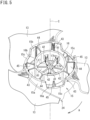
- FIG. 6 is a view illustrating the hub of the axial-flow fan as seen from the second side in the rotation axis direction.
- the hub 12 has an outer wall 15, an inner wall 16, a boss 17, and a sidewall 18.
- the outer wall 15 has a tubular shape. Specifically, the outer wall 15 has a cylindrical shape. The outer wall 15 has a center aligned with the center axis C of the axial-flow fan 11. The outer wall 15 has an outer peripheral surface 15a corresponding to the outer peripheral surface of the hub 12. The blades 13 are connected to the outer peripheral surface 15a of the outer wall 15.
- the inner wall 16 has a tubular shape. Specifically, the inner wall 16 has a cylindrical shape. The inner wall 16 is located radially inward of the outer wall 15. The inner wall 16 has a center aligned with the center of the outer wall 15.
- the boss 17 has a tubular shape. Specifically, the boss 17 has a cylindrical shape. The boss 17 is located radially inward of the inner wall 16. The boss 17 has a center aligned with the center of the inner wall 16 and the center of the outer wall 15. The boss 17 has a through hole 17a passing through the center of the boss 17. An output shaft of a motor (not illustrated) is inserted in the through hole 17a and attached to the boss 17.
- FIG. 7 is a schematic sectional view taken along line D-D in FIG. 6 .
- FIG. 8 is a schematic sectional view taken along line E-E in FIG. 6 .
- FIG. 9 is a schematic sectional view taken along line F-F in FIG. 6 .
- the inner wall 16 is shorter in axial length than the outer wall 15. An end portion, closer to the first side in the rotation axis direction, of the inner wall 16 is located closer to the second side in the rotation axis direction (e.g., the upper side in FIG. 8 ) than an end portion, closer to the first side in the rotation axis direction, of the outer wall 15 is. An end portion, closer to the second side in the rotation axis direction, of the inner wall 16 is located closer to the first side in the rotation axis direction (e.g., the lower side in FIG. 8 ) than an end portion, closer to the second side in the rotation axis direction, of the outer wall 15 is.
- the sidewall 18 is located on the end portions, closer to the first side in the rotation axis direction, of the outer wall 15, inner wall 16, and boss 17.
- the sidewall 18 closes the end portions, closer to the first side in the rotation axis direction, of the outer wall 15 and inner wall 16 each having a cylindrical shape.
- the sidewall 18 corresponds to an end surface, closer to the first side in the rotation axis direction, of the hub 12.
- the sidewall 18 includes a first sidewall 21 and a second sidewall 22.
- the first sidewall 21 connects the end portion, closer to the first side in the rotation axis direction, of the outer wall 15 and the end portion, closer to the first side in the rotation axis direction, of the inner wall 16.
- the second sidewall 22 connects the end portion, closer to the first side in the rotation axis direction, of the inner wall 16 and the end portion, closer to the first side in the rotation axis direction, of the boss 17.
- the first sidewall 21 has an annular portion 21a and a slanted portion 21b located radially inward of the annular portion 21a.
- the annular portion 21a has an annular shape, and extends in a direction orthogonal to the center axis C of the axial-flow fan 11.
- the annular portion 21a has a radially outer end portion connected to the end portion, closer to the first side in the rotation axis direction, of the outer wall 15.
- the slanted portion 21b has a conical shape, and extends obliquely to the center axis C of the axial-flow fan 11.
- the slanted portion 21b has a radially outer end portion connected to a radially inner end portion of the annular portion 21a.
- the slanted portion 21b also has a radially inner end portion connected to the end portion, closer to the first side in the rotation axis direction, of the inner wall 16.
- the second sidewall 22 has an annular shape, and extends in a direction orthogonal to the center axis C of the axial-flow fan 11.
- the second sidewall 22 has a radially outer end portion connected to the radially inner end portion of the slanted portion 21b and the end portion, closer to the first side in the rotation axis direction, of the inner wall 16.
- the second sidewall 22 also has a radially inner end portion connected to the end portion, closer to the first side in the rotation axis direction, of the boss 17.
- the second sidewall 22 closes the end portion, closer to the first side in the rotation axis direction, of the inner wall 16 having a cylindrical shape.
- the sidewall 18 has a recessed portion 18a defined by the slanted portion 21b and the second sidewall 22 and recessed toward the second side in the rotation axis direction.
- the slanted portion 21b corresponds to a peripheral wall of the recessed portion 18a.
- the second sidewall 22 corresponds to a bottom wall of the recessed portion 18a.
- the sidewall 18 has a protrusion 24 protruding toward the first side in the rotation axis direction.
- the annular portion 21a of the first sidewall 21 has the protrusion 24.
- the annular portion 21a has a plurality of protrusions 24 spaced apart from each other in the circumferential direction. In the present embodiment, three protrusions 24 are equally spaced by 120° apart from each other in the circumferential direction.
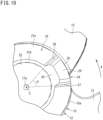
- FIG. 10 is a view illustrating a part of the hub of the axial-flow fan as seen from the first side in the rotation axis direction.
- Each protrusion 24 extends within a range of a center angle ⁇ , which is less than 60°, about the center axis C of the axial-flow fan 11.
- the protrusion 24 has an outer wall portion (a first wall portion) 25, an inner wall portion (a second wall portion) 26, a pair of end wall portions (a third wall portion and a fourth wall portion) 27 and 28, and a top wall portion (a fifth wall portion) 29.
- the outer wall portion 25 extends from the outer wall 15 of the hub 12, toward the first side in the rotation axis direction.
- the outer wall portion 25 has an outer peripheral surface 25a that is flush with the outer peripheral surface 15a of the outer wall 15.
- the outer wall portion 25 extends in the circumferential direction of the hub 12, and curves in an arc shape as seen in the rotation axis direction.
- the inner wall portion 26 of the protrusion 24 extends from the slanted portion 21b of the first sidewall 21 of the hub 12, toward the first side in the rotation axis direction.
- the inner wall portion 26 has an inner peripheral surface 26b that is flush with an inner peripheral surface 21b 1 of the slanted portion 21b (i.e., an inner peripheral surface 21b1 of the recessed portion 18a).
- the inner wall portion 26 extends obliquely to the center axis C.
- the inner wall portion 26 extends in the circumferential direction of the hub 12, and curves in an arc shape as seen in the rotation axis direction.
- the outer peripheral surface 25a of the outer wall portion 25 is connected to an end portion, closer to the rear side in the rotational direction A, of each blade 13 (see FIG. 4 ).
- the inner wall portion 26 is located radially inward of the outer wall portion 25, and is spaced apart from the outer wall portion 25.
- the outer wall portion 25 is located opposite the inner wall portion 26 in the radial direction.
- FIG. 11 is a schematic sectional view taken along line G-G in FIG. 9 .
- the pair of end wall portions 27 and 28 are located on two ends of the protrusion 24 so as to face each other in the circumferential direction.
- the pair of end wall portions 27 and 28 extend in the radial direction of the hub 12.
- Each of the end wall portions 27 and 28 extends from the annular portion 21a of the first sidewall 21, toward the first side in the rotation axis direction.
- Each of the end wall portions 27 and 28 has such a trapezoidal shape that a radial length, closer to the first side in the rotation axis direction, is shorter.
- the radial length of each of the end wall portions 27 and 28 is shorter than a circumferential length of each of the outer wall portion 25 and the inner wall portion 26.
- the protrusion 24 has a substantially rectangular section orthogonal to the center axis C, and this section is defined by the outer wall portion 25, the inner wall portion 26, and the pair of end wall portions 27 and 28.
- the protrusion 24 has a space S3 defined by the outer wall portion 25, the inner wall portion 26, and the pair of end wall portions 27 and 28. In other words, the interior of the protrusion 24 is hollow.
- the space S3 in the protrusion 24 communicates with a space S4 defined between the outer wall 15 and the inner wall 16 of the hub 12.
- the space S3 in the protrusion 24 is closed with the top wall portion 29 at the first side in the rotation axis direction.
- the top wall portion 29 extends in a direction orthogonal to the center axis C of the axial-flow fan 11.
- a plate-shaped rib (a third outer rib 45) to be described later is located in the space S3 in the protrusion 24.
- the rib 45 extends from the space S3 in the protrusion 24 toward the second side in the rotation axis direction, and reaches the space S4 in the hub 12.
- the outer wall 15 has a plurality of recessed portions 15c. Specifically, each recessed portion 15c is located in the end portion, closer to the second side in the rotation axis direction, of the outer wall 15. Each recessed portion 15c is equal in phase to the corresponding protrusion 24 in the circumferential direction.
- FIG. 12 is an explanatory view illustrating a state in which a plurality of axial-flow fans are stacked on top of each other.
- Each recessed portion 15c has a trapezoidal shape as seen from the outside in the radial direction.
- Each protrusion 24 also has a trapezoidal shape as seen from the outside in the radial direction.
- the recessed portion 15c is larger in outside shape than the protrusion 24 as seen from the outside in the radial direction.
- a circumferential length L1 of an open end (i.e., a lower end in FIG. 12 ) of the recessed portion 15c is slightly longer than a circumferential length L2 of a root portion of the protrusion 24.
- a circumferential length L3 of a bottom portion of the recessed portion 15c is slightly longer than a circumferential length L4 of a distal end portion of the protrusion 24.
- a length (i.e., a depth) L5 of the recessed portion 15c in the rotation axis direction is slightly longer than a length (i.e., a height) L6 of the protrusion 24.
- the axial-flow fans 11, after manufacture, are stacked in the rotation axis direction for storage and transportation purposes.
- the protrusion 24 is located on the end surface located closer to the first side in the rotation axis direction of the axial-flow fan 11, and the recessed portion 15c is located in the end surface closer to the second side in the rotation axis direction of the axial-flow fan 11.
- the protrusion 24 of a lower one of the axial-flow fans 11 is inserted in the recessed portion 15c of an upper one of the axial-flow fans 11.
- This configuration thus enables reduction in total height of the stacked axial-flow fans 11 in the stacking direction as much as possible.
- This configuration also enables reduction in circumferential displacement of the axial-flow fans 11 arranged in the stacking direction.
- the hub 12 has a plurality of ribs 41, 42, 43, 44, and 45.
- the hub 12 according to the present embodiment has outer ribs 43, 44, and 45, and inner ribs 41 and 42.
- the outer ribs 43, 44, and 45 are located between the outer wall 15 and the inner wall 16.
- the inner ribs 41 and 42 are located between the inner wall 16 and the boss 17.
- Each of the ribs 41, 42, 43, 44, and 45 has a plate shape and extends in the radial direction from the center axis C of the axial-flow fan 11.
- Each of the ribs 41, 42, 43, 44, and 45 may alternatively extend in a direction oblique to the radial direction.
- the inner ribs 41 and 42 connect an inner peripheral surface 16b of the inner wall 16 and an outer peripheral surface 17b of the boss 17.
- the hub 12 has six inner ribs 41 and 42 spaced apart from each other in the circumferential direction. These inner ribs include three first inner ribs 41 and three second inner ribs 42.
- the first inner ribs 41 and the second inner ribs 42 are arranged alternately in the circumferential direction. Attention is now focused on a certain one of the first inner ribs 41.
- the first inner rib 41 and the second inner rib 42 adjacent thereto at the first side in the circumferential direction form an angle ⁇ 1.
- the first inner rib 41 and the second inner rib 42 adjacent thereto at the second side in the circumferential direction form an angle ⁇ 2.
- the angle ⁇ 1 and the angle ⁇ 2 satisfy a relation of ⁇ 1 ⁇ ⁇ 2.
- the first inner rib 41 and the second inner rib 42 that form the angle ⁇ 1 constitute a set X.
- the hub 12 according to the present embodiment has three sets X respectively constituted of the first inner ribs 41 and the second inner ribs 42. These sets X are spaced apart from each other in the circumferential direction.
- the axial-flow fan 11 includes the three blades 13. Therefore, the angle ⁇ 1 satisfies the following relation (2). ⁇ 1 ⁇ 60 °
- the angle ⁇ 2 between one of the sets X and the adjacent set X satisfies the following relation (3). ⁇ 2 ⁇ 360 / 2 N °
- the axial-flow fan 11 includes the three blades 13. Therefore, the angle ⁇ 2 satisfies the following relation (4). ⁇ 2 ⁇ 60 °
- an end portion 41c, closer to the second side in the rotation axis direction, of each first inner rib 41 and an end portion 17c, closer to the second side in the rotation axis direction, of the boss 17 are located at the same position in the rotation axis direction.
- the end portion 41c, closer to the second side in the rotation axis direction, of each first inner rib 41 is located closer to the first side in the rotation axis direction (e.g., the lower side in FIG. 8 ) than an end portion 16c, closer to the second side in the rotation axis direction, of the inner wall 16 is.
- the second inner ribs 42 are equal in shape to the first inner ribs 41. Therefore, the positional relationships between each second inner rib 42 and the boss 17 and inner wall 16 in the rotation axis direction are also equal to the positional relationships between each first inner rib 41 and the boss 17 and inner wall 16 in the rotation axis direction.
- the outer ribs 43, 44, and 45 connect an inner peripheral surface 15b of the outer wall 15 and an outer peripheral surface 16a of the inner wall 16.
- the hub 12 has nine outer ribs 43, 44, and 45 spaced apart from each other in the circumferential direction.
- the nine outer ribs 43, 44, and 45 are equally spaced apart from each other in the circumferential direction.
- the outer ribs 43, 44, and 45 each have a plate shape, and are smaller in thickness than the inner ribs 41 and 42.
- the inner ribs 41 and 42 are smaller in number than the outer ribs 43, 44, and 45, but are larger in thickness than the outer ribs 43, 44, and 45, which therefore contribute to improvement in strength.
- the outer ribs 43, 44, and 45 include three first outer ribs 43, three second outer ribs 44, and three third outer ribs 45. These outer ribs are arranged ordinary. For example, the first outer rib 43, the second outer rib 44, the third outer rib 45, the first outer rib 43, the second outer rib 44, the third outer rib 45, the first outer rib 43, the second outer rib 44, and the third outer rib 45 are arranged in this order in the opposite direction to the rotational direction A.
- first outer ribs 43, second outer ribs 44, and third outer ribs 45 are provided for each blade 13.
- the first outer rib 43 has a radially outer end portion located near a radially inner end portion of the front edge portion 33 of the blade 13.
- the third outer rib 45 has a radially outer end portion located near a radially inner end portion of the rear edge portion 34 of the blade 13.
- the second outer rib 44 has a radially outer end portion located in correspondence with a middle portion of the blade 13 in the rotational direction A.
- each first outer rib 43 is located between the first inner rib 41 and the second inner rib 42, which constitute the corresponding set X, in the circumferential direction.
- each first outer rib 43 has a radially inner end portion 43a located between a radially outer end portion 41b of the corresponding first inner rib 41 and a radially outer end portion 42b of the corresponding second inner rib 42 in the circumferential direction.
- an end portion 43c, closer to the second side in the rotation axis direction, of each first outer rib 43 is located closer to the second side in the rotation axis direction (e.g., the upper side in FIG. 7 ) than an end portion 42c, closer to the second side in the rotation axis direction, of each second inner rib 42 is.
- the end portion 43c, closer to the second side in the rotation axis direction, of each first outer rib 43 is flush with the end portion 16c, closer to the second side in the rotation axis direction, of the inner wall 16 at a joint between the first outer rib 43 and the inner wall 16.
- the second outer ribs 44 are equal in shape to the first outer ribs 43. Therefore, the positional relationships between each second outer rib 44 and the corresponding first inner rib 41 (and second inner rib 42) and inner wall 16 in the rotation axis direction are equal to the positional relationships between each first outer rib 43 and the corresponding first inner rib 41 (and second inner rib 42) and inner wall 16 in the rotation axis direction.
- each third outer rib 45 is located in the space S3 in the corresponding protrusion 24 as described above.
- Each third outer rib 45 extends from the space S3 in the corresponding protrusion 24 to the space S4 between the outer wall 15 and the inner wall 16, toward the second side in the rotation axis direction.
- An end portion 45c, closer to the second side in the rotation axis direction, of each third outer rib 45 extends to the slanted portion 21b of the first sidewall 21, and reaches the inner wall 16 beyond the slanted portion 21b.
- each third outer rib 45 is located closer to the first side in the rotation axis direction than the bottom portion of the recessed portion 15c in the outer wall 15 is.
- the end portion 45c, closer to the second side in the rotation axis direction, of each third outer rib 45 is located closer to the first side in the rotation axis direction than the end portion 42c, closer to the second side in the rotation axis direction, of each second inner rib 42 is.
- the axial-flow fan 11 having the foregoing configuration generates a centrifugal force by rotation, so that a load traveling through each blade 13 is imposed on the hub 12 to pull the hub 12 radially outward.
- the hub 12 according to the present embodiment has the first outer ribs 43, the second outer ribs 44, and the third outer ribs 45. These outer ribs 43, 44, and 45 are capable of supporting the outer wall 15 of the hub 12 against the radial load that travels through each blade 13 and then reaches the outer wall 15.
- the hub 12 receives the maximum radial load at a position near the front edge portion 33 of each blade 13.
- the radially inner end portion 43a of each first outer rib 43 which is located near the radially inner end portion of the front edge portion 33 of the corresponding blade 13, is located between the first inner rib 41 and the second inner rib 42, which constitute the corresponding set X, in the circumferential direction. Therefore, the first inner rib 41 and the second inner rib 42 are capable of receiving, together with the first outer rib 43, the large load imposed on the outer wall 15 through the position near the front edge portion 33 of each blade 13, via the inner wall 16. This configuration therefore further improves the strength of the hub 12, and causes the hub 12 to further resist deformation.
- the hub 12 also receives, in addition to the radial load, a circumferential load traveling through each blade 13.
- the hub 12 has the protrusions 24 on the end surface, closer to the first side in the rotation axis direction, of the hub 12.
- the protrusions 24 each have the outer wall portion 25 and the inner wall portion 26 each extending in the circumferential direction, and the pair of end wall portions 27 and 28 each extending in the radial direction.
- the protrusions 24 each have the substantially rectangular section in the direction orthogonal to the center axis C (see FIG. 11 ).
- the pair of end wall portions 27 and 28 are capable of causing the hub 12 to resist deformation mainly owing to the radial load imposed on the hub 12.
- the outer wall portion 25 and the inner wall portion 26 are capable of causing the hub 12 to resist deformation mainly owing to the circumferential load imposed on the hub 12. Therefore, the protrusions 24 allow the hub 12 to have a structure resistant to both the radial load and the circumferential load. The strength of the hub 12 is thus improved.
- Each blade 13 is partly connected to the outer wall portion 25 of the corresponding protrusion 24, so that the outer wall portion 25 directly receives the radial load and the circumferential load from the blade 13.
- the protrusion 24 having the substantially rectangular section is capable of suitably supporting the outer wall 15 of the hub 12 against these loads.
- FIG. 13 is a schematic plan view illustrating an inside of an air conditioner including the axial-flow fan according to the present disclosure, as seen from above.
- FIG. 13 illustrates an outdoor unit 51 of an air conditioner 50.
- the air conditioner 50 is of a separate type and includes an outdoor unit and an indoor unit provided separately from the outdoor unit.
- the outdoor unit 51 includes the axial-flow fan 11.
- the outdoor unit 51 includes a housing 52.
- the housing 52 has a rectangular parallelepiped shape.
- the outdoor unit 51 also includes a partition 53 dividing the housing 52 into a machine chamber S1 and a heat exchange chamber S2.
- the housing 52 has adjacent sidewalls 52a and 52b located in the heat exchange chamber S2, and the sidewalls 52a and 52b respectively have air intake ports 52a1 and 52b1.
- the housing 52 also has a sidewall 52c adjacent to the sidewall 52b having the air intake port 52b1, and the sidewall 52c has an air blow-out port 52c1.
- the housing 52 houses, in the machine chamber S1, a compressor 54, a four-way switching valve (not illustrated), an accumulator (not illustrated), an oil separator (not illustrated), an expansion valve (not illustrated), and the like.
- the housing 52 also houses, in the heat exchange chamber S2, a heat exchanger 55, a fan motor 56, the axial-flow fan 11, and the like.
- the axial-flow fan 11 is connected to the fan motor 56 with a shaft 56a, and is driven by the fan motor 56 to rotate about the shaft 56a.
- the shaft 56a is mounted to the boss 17 (see, for example, FIGs. 2 , 5 ) of the axial-flow fan 11.
- the axial-flow fan 11 is placed with the positive pressure surface 13a (see FIG. 3 ) facing the sidewall 52c having the air blow-out port 52c1 and the negative pressure surface 13b (see FIG. 3 ) facing the sidewall 52a having the air intake port 52a1.
- the axial-flow fan 11 rotates. Air is thus taken in the housing 52 through the air intake ports 52a1 and 52b1, and is then blown out of the housing 52 through the air blow-out port 52c1.
- arrows "a” each indicate a flow of air taken in the housing 52 through the air intake ports 52a1 and 52b1
- arrows "b” each indicate a flow of air blown out of the housing 52 through the air blow-out port 52c 1.
- the heat exchanger 55 has an "L" shape in plan view.
- the heat exchanger 55 bends at a position near a corner portion 52e between the sidewalls 52a and 52b respectively having the air intake ports 52a1 and 52b1, and extends along the sidewalls 52a and 52b.
- the heat exchanger 55 includes a pair of headers 61 and 62, a group of fins 63 arranged side by side such that their plate-shaped faces extend in parallel, and a heat transfer tube 64 passing through the group of fins 63 arranged side by side.
- the heat exchanger 55 is connected to the compressor 54 in the machine chamber S1 with a pipe (not illustrated).
- the outdoor unit 51 includes the axial-flow fan 11.
- an indoor unit (not illustrated) may include the axial-flow fan 11.
- the air conditioner 50 may include the axial-flow fan 11 placed with the axis of rotation extending in an up-and-down direction.
- An axial-flow fan 11 includes a hub 12 and a plurality of blades 13 disposed on an outer peripheral surface of the hub 12 and spaced apart from each other in a circumferential direction.
- the hub 12 includes: an outer wall 15 having a tubular shape; an inner wall 16 having a tubular shape, the inner wall 16 being located radially inward of the outer wall 15; a boss 17 to which a shaft is mounted, the boss 17 being located radially inward of the inner wall 16; a first sidewall 21 connecting an end portion, closer to a first side in an rotation axis direction of the hub 12, of the outer wall 15 and an end portion, closer to the first side in the rotation axis direction, of the inner wall 16; a second sidewall 22 connecting the end portion, closer to the first side in the rotation axis direction, of the inner wall 16 and an end portion, closer to the first side in the rotation axis direction, of the boss 17; a first inner rib (a first rib) 41 connecting an inner peripheral surface of the inner wall
- the radially inner end portion of the single first outer rib 43 is located between the radially outer end portion of the first inner rib 41 and the radially outer end portion of the second inner rib 42 in the circumferential direction. Therefore, the single first outer rib 43 can be reinforced with the first inner rib 41 and second inner rib 42.
- the first outer rib 43 has a radially outer end portion located near a radially inner end portion of a front edge portion 33 of each blade 13 in a rotational direction A of the hub 12.
- the front edge portion 33 of each blade 13 in the rotational direction of the hub 12 corresponds to a portion where the maximum load resulting from air is imposed.
- the load imposed on the outer wall 15 of the hub 12 through each blade 13 also increases at the position near the radially inner end portion of the front edge portion 33 of each blade 13.
- the radially outer end portion of the first outer rib 43 is located near the radially inner end portion of the front edge portion 33 of each blade 13. This configuration thus enables effective improvement in strength of the hub 12 at the portion where the large load is imposed through each blade 13.
- the first inner rib 41 and the second inner rib 42 are arranged in the radial direction of the hub 12, and an angle between the first inner rib 41 and the second inner rib 42 satisfies the following relation (1): ⁇ ⁇ 360 / 2 N (where ⁇ represents the angle between the first rib and the second rib, and N represents the number of blades).
- a spacing between the first inner rib 41 and the second inner rib 42 is set to satisfy the foregoing relation (1).
- the hub 12 includes: a first set X including a combination of the first inner rib 41 and the second inner rib 42; and a second set X including a combination of the first inner rib 41 and the second inner rib 42 that are different from the first inner rib 41 and the second inner rib 42 in the first set X, the second set X being adjacent to the first set X in the circumferential direction.
- An angle between the first set X and the second set X is larger than an angle between the first inner rib 41 and the second inner rib 42 in each of the first set X and the second set X. According to this configuration, the first outer rib 43 can be effectively reinforced with the first inner rib 41 and the second inner rib 42 in each set X.
- the hub 12 further includes a third outer rib (a fourth rib) 45 located between the first set X and the second set X in the circumferential direction, the third outer rib 45 connecting the inner peripheral surface 15b of the outer wall 15 and the outer peripheral surface 16a of the inner wall 16.
- the third outer rib 45 has a radially outer end portion located near a radially inner end portion of a rear edge portion 34 of each blade 13 in the rotational direction A of the hub 12.
- the number of outer ribs is not limited to that described in the foregoing embodiment, and is changeable as appropriate.
- a plurality of second outer ribs 44 may be disposed between each first outer rib 43 and the adjacent third outer rib 45.
- no second outer rib 44 may be disposed between each first outer rib 43 and the adj acent third outer rib 45.
- the number of inner ribs is not limited to that described in the foregoing embodiment, and is changeable as appropriate.
- the number of sets corresponding to the combinations of the first inner ribs and the second inner ribs is changeable in accordance with the number of blades 13. Two or more outer ribs may be disposed between the first inner rib and the second inner rib that constitute each set.
- the sidewall 18 of the hub 12 does not necessarily have the recessed portion 18a.
- the number of protrusions 24 is changeable as appropriate in accordance with the number of blades 13.
Landscapes
- Engineering & Computer Science (AREA)
- Mechanical Engineering (AREA)
- General Engineering & Computer Science (AREA)
- Structures Of Non-Positive Displacement Pumps (AREA)
Abstract
Description
- The present disclosure relates to an axial-flow fan and an air conditioner.
-
Patent Literature 1 listed below discloses an axial-flow fan including a hub and a plurality of blades disposed on an outer peripheral surface of the hub. The hub includes an outer wall portion having a cylindrical shape, a slanted wall portion located radially inward of the outer wall portion, and a bearing portion located radially inward of the slanted wall portion. The hub also includes a plurality of ribs arranged radially. The ribs are located between the outer wall portion and the slanted wall portion, and are spaced apart from each other in a circumferential direction. - PATENT LITERATURE 1:
Japanese Laid-Open Patent Publication No. 2006-161758 - During the rotation of the axial-flow fan, a load traveling through each blade is imposed on the outer wall portion of the hub to pull the hub radially outward. This load causes the outer wall portion of the hub to deform so as to expand radially outward. It has therefore been required to improve the strength of the hub in order to cause the hub to resist deformation.
- An object of the present disclosure is to provide an axial-flow fan including a hub with improved strength, and an air conditioner including the axial-flow fan.
- The present disclosure provides an axial-flow fan including:
- a hub; and
- a plurality of blades disposed on an outer peripheral surface of the hub and spaced apart from each other in a circumferential direction,
- in which
- the hub includes:
- an outer wall having a tubular shape;
- an inner wall having a tubular shape,
- the inner wall being located radially inward of the outer wall;
- a boss to which a shaft is mounted,
- the boss being located radially inward of the inner wall;
- a first sidewall connecting an end portion, closer to a first side in a rotation axis direction of the hub, of the outer wall and an end portion, closer to the first side in the rotation axis direction, of the inner wall;
- a second sidewall connecting the end portion, closer to the first side in the rotation axis direction, of the inner wall and an end portion, closer to the first side in the rotation axis direction, of the boss;
- a first rib connecting an inner peripheral surface of the inner wall and an outer peripheral surface of the boss;
- a second rib adjacent to the first rib in the circumferential direction,
- the second rib connecting the inner peripheral surface of the inner wall and the outer peripheral surface of the boss; and
- a third rib connecting an inner peripheral surface of the outer wall and an outer peripheral surface of the inner wall,
- the third rib having a radially inner end portion located between a radially outer end portion of the first rib and a radially outer end portion of the second rib in the circumferential direction.
- According to the axial-flow fan having this configuration, when the axial-flow fan rotates, a load traveling through each blade is imposed on the outer wall of the hub to pull the hub radially outward. The outer wall of the hub is supported by the third rib, and is further supported by the first rib and the second rib through the inner wall. This configuration thus allows the hub to have a structure resistant to the radial load, and causes the hub to resist deformation.
- Preferably, the radially inner end portion of the single third rib is located between the radially outer end portion of the first rib and the radially outer end portion of the second rib in the circumferential direction.
- Preferably, the third rib has a radially outer end portion located near a radially inner end portion of a front edge portion of each blade in a rotational direction of the hub.
- According to this configuration, the front edge portion of each blade in the rotational direction of the hub corresponds to a portion where the maximum load resulting from air is imposed. In addition, the load imposed on the outer wall of the hub through each blade also increases at the position near the radially inner end portion of the front edge portion of each blade. In view of this, the radially inner end portion of the third rib is located near the radially inner end portion of the front edge portion of each blade. This configuration thus enables effective improvement in strength of the hub at the portion where the large load is imposed through each blade.
- Preferably, the first rib and the second rib are arranged in a radial direction of the hub, and
an angle between the first rib and the second rib satisfies the following relation (1):
- Preferably, the hub includes:
- a first set including a combination of the first rib and the second rib; and
- a second set including a combination of the first rib and the second rib that are different from the first rib and the second rib in the first set,
- the second set being adjacent to the first set in the circumferential direction, and
- an angle between the first set and the second set is larger than an angle between the first rib and the second rib in each of the first set and the second set.
- Preferably, the hub further includes a fourth rib located between the first set and the second set in the circumferential direction, the fourth rib connecting the inner peripheral surface of the outer wall and the outer peripheral surface of the inner wall.
- Preferably, the fourth rib has a radially outer end portion located near a radially inner end portion of a rear edge portion of each blade in a rotational direction of the hub.
- Preferably, end portions, closer to a second side in the rotation axis direction, of the first and second ribs are located closer to the first side in the rotation axis direction than an end portion, closer to the second side in the rotation axis direction, of the third rib is.
- Preferably, end portions, closer to a second side in the rotation axis direction, of the first and second ribs are located closer to the first side in the rotation axis direction than an end portion, closer to the second side in the rotation axis direction, of the inner wall is.
- Preferably, an end portion, closer to a second side in the rotation axis direction, of the third rib is flush with an end portion, closer to the second side in the rotation axis direction, of the inner wall, at a joint between the third rib and the inner wall.
- Preferably, the first rib and the second rib are larger in thickness than the third rib.
- The present disclosure also provides an air conditioner including the axial-flow fan described above.
-
-
FIG. 1 is a view illustrating an axial-flow fan according to the present disclosure as seen from a first side in a rotation axis direction. -
FIG. 2 is a view illustrating the axial-flow fan according to the present disclosure as seen from a second side in the rotation axis direction. -
FIG. 3 is a view illustrating the axial-flow fan according to the present disclosure as seen in a direction orthogonal to the rotation axis direction. -
FIG. 4 is a perspective view illustrating a hub of the axial-flow fan as seen obliquely from the first side in the rotation axis direction. -
FIG. 5 is a perspective view illustrating the hub of the axial-flow fan as seen obliquely from the second side in the rotation axis direction. -
FIG. 6 is a view illustrating the hub of the axial-flow fan as seen from the second side in the rotation axis direction. -
FIG. 7 is a schematic sectional view taken along line D-D inFIG. 6 . -
FIG. 8 is a schematic sectional view taken along line E-E inFIG. 6 . -
FIG. 9 is a schematic sectional view taken along line F-F inFIG. 6 . -
FIG. 10 is a view illustrating a part of the hub of the axial-flow fan as seen from the first side in the rotation axis direction. -
FIG. 11 is a schematic sectional view taken along line G-G inFIG. 9 . -
FIG. 12 is an explanatory view illustrating a state in which a plurality of axial-flow fans are stacked on top of each other. -
FIG. 13 is a schematic plan view illustrating an inside of an air conditioner including the axial-flow fan according to the present disclosure, as seen from above. - Embodiments will be described below.
-
FIG. 1 is a view illustrating an axial-flow fan according to the present disclosure as seen from a first side in a rotation axis direction.FIG. 2 is a view illustrating the axial-flow fan according to the present disclosure as seen from a second side in the rotation axis direction.FIG. 3 is a view illustrating the axial-flow fan according to the present disclosure as seen in a direction orthogonal to the rotation axis direction. - An axial-
flow fan 11 is driven by a fan motor (not illustrated) to rotate about a center axis C. Accordingly, the center axis C of the axial-flow fan 11 corresponds to an axis of rotation of the axial-flow fan 11. In this specification, therefore, reference sign C also denotes the axis of rotation of the axial-flow fan 11, in addition to the center axis of the axial-flow fan 11. In this specification, the term "rotation axis direction" as used herein refers to a direction along which the center axis C of the axial-flow fan 11 extends and a direction parallel to this direction. The term "radial direction" as used herein refers to a direction orthogonal to the center axis C of the axial-flow fan 11. The term "circumferential direction" as used herein refers to a direction around the center axis C of the axial-flow fan 11. - As illustrated in
FIGs. 1 to 3 , the axial-flow fan 11 is a propeller fan. The axial-flow fan 11 is made of, for example, a synthetic resin material such as an acrylonitrile-styrene (AS) copolymer, or a synthetic resin material reinforced with glass fiber. The axial-flow fan 11 includes ahub 12 and a plurality ofblades 13. The plurality ofblades 13 are disposed on an outer peripheral surface of thehub 12, and are spaced apart from each other in the circumferential direction. The axial-flow fan 11 according to the present embodiment includes threeblades 13. Thehub 12 and theblades 13 are integrally formed with a synthetic resin material. It should be noted that the material for the axial-flow fan 11 is not limited to the foregoing synthetic resin and is changeable as appropriate. - As illustrated in
FIG. 1 , the axial-flow fan 11 rotates counterclockwise (i.e., in a direction indicated by an arrow A) as seen from the first side in the rotation axis direction. In this specification, a front side and a rear side in a rotational direction are defined with respect to a rotational direction of the axial-flow fan 11. - As illustrated in
FIGs. 1 to 3 , eachblade 13 has a plate shape and includes an innerperipheral edge portion 31, an outerperipheral edge portion 32, afront edge portion 33, and arear edge portion 34. The innerperipheral edge portion 31 corresponds to a radially inner end portion of theblade 13. The innerperipheral edge portion 31 is slanted to the first side in the rotation axis direction, from the front side in the rotational direction toward the rear side in the rotational direction. The innerperipheral edge portion 31 is connected to the outer peripheral surface of thehub 12. - The outer
peripheral edge portion 32 corresponds to a radially outer end portion of theblade 13. The outerperipheral edge portion 32 is slanted to the first side in the rotation axis direction, from the front side in the rotational direction toward the rear side in the rotational direction. The outerperipheral edge portion 32 is longer in circumferential length than the innerperipheral edge portion 31. - The
front edge portion 33 corresponds to an end portion, closer to the front side in the rotational direction, of theblade 13. Thefront edge portion 33 connects an end portion, closer to the front side in the rotational direction, of the innerperipheral edge portion 31 and an end portion, closer to the front side in the rotational direction, of the outerperipheral edge portion 32. Therear edge portion 34 corresponds to an end portion, closer to the rear side in the rotational direction, of theblade 13. Therear edge portion 34 connects an end portion, closer to the rear side in the rotational direction, of the innerperipheral edge portion 31 and an end portion, closer to the rear side in the rotational direction, of the outerperipheral edge portion 32. - The axial-
flow fan 11, when rotating about the center axis C in the direction indicated by the arrow A, generates a negative pressure at the second side in the rotation axis direction and also generates a positive pressure at the first side in the rotation axis direction. Therefore, the axial-flow fan 11, when rotating about the center axis C in the direction indicated by the arrow A, causes air to flow from the second side in the rotation axis direction to the first side in the rotation axis direction. In this specification, the term "positive pressure surface 13a" refers to a blade surface, closer to the first side in the rotation axis direction, of theblade 13, and the term "negative pressure surface 13b" refers to a blade surface, closer to the second side in the rotation axis direction, of theblade 13. - The
blade 13 curves gently toward the second side in the rotation axis direction as seen in the circumferential direction such that thepositive pressure surface 13a is recessed. -
FIG. 4 is a perspective view illustrating the hub of the axial-flow fan as seen obliquely from the first side in the rotation axis direction.FIG. 5 is a perspective view illustrating the hub of the axial-flow fan as seen obliquely from the second side in the rotation axis direction.FIG. 6 is a view illustrating the hub of the axial-flow fan as seen from the second side in the rotation axis direction. - The
hub 12 has anouter wall 15, aninner wall 16, aboss 17, and asidewall 18. - The
outer wall 15 has a tubular shape. Specifically, theouter wall 15 has a cylindrical shape. Theouter wall 15 has a center aligned with the center axis C of the axial-flow fan 11. Theouter wall 15 has an outerperipheral surface 15a corresponding to the outer peripheral surface of thehub 12. Theblades 13 are connected to the outerperipheral surface 15a of theouter wall 15. - The
inner wall 16 has a tubular shape. Specifically, theinner wall 16 has a cylindrical shape. Theinner wall 16 is located radially inward of theouter wall 15. Theinner wall 16 has a center aligned with the center of theouter wall 15. - The
boss 17 has a tubular shape. Specifically, theboss 17 has a cylindrical shape. Theboss 17 is located radially inward of theinner wall 16. Theboss 17 has a center aligned with the center of theinner wall 16 and the center of theouter wall 15. Theboss 17 has a throughhole 17a passing through the center of theboss 17. An output shaft of a motor (not illustrated) is inserted in the throughhole 17a and attached to theboss 17. -
FIG. 7 is a schematic sectional view taken along line D-D inFIG. 6 .FIG. 8 is a schematic sectional view taken along line E-E inFIG. 6 .FIG. 9 is a schematic sectional view taken along line F-F inFIG. 6 . - In the
hub 12, theinner wall 16 is shorter in axial length than theouter wall 15. An end portion, closer to the first side in the rotation axis direction, of theinner wall 16 is located closer to the second side in the rotation axis direction (e.g., the upper side inFIG. 8 ) than an end portion, closer to the first side in the rotation axis direction, of theouter wall 15 is. An end portion, closer to the second side in the rotation axis direction, of theinner wall 16 is located closer to the first side in the rotation axis direction (e.g., the lower side inFIG. 8 ) than an end portion, closer to the second side in the rotation axis direction, of theouter wall 15 is. - In the
hub 12, thesidewall 18 is located on the end portions, closer to the first side in the rotation axis direction, of theouter wall 15,inner wall 16, andboss 17. Thesidewall 18 closes the end portions, closer to the first side in the rotation axis direction, of theouter wall 15 andinner wall 16 each having a cylindrical shape. Thesidewall 18 corresponds to an end surface, closer to the first side in the rotation axis direction, of thehub 12. - The
sidewall 18 includes afirst sidewall 21 and asecond sidewall 22. Thefirst sidewall 21 connects the end portion, closer to the first side in the rotation axis direction, of theouter wall 15 and the end portion, closer to the first side in the rotation axis direction, of theinner wall 16. Thesecond sidewall 22 connects the end portion, closer to the first side in the rotation axis direction, of theinner wall 16 and the end portion, closer to the first side in the rotation axis direction, of theboss 17. - The
first sidewall 21 has anannular portion 21a and aslanted portion 21b located radially inward of theannular portion 21a. Theannular portion 21a has an annular shape, and extends in a direction orthogonal to the center axis C of the axial-flow fan 11. Theannular portion 21a has a radially outer end portion connected to the end portion, closer to the first side in the rotation axis direction, of theouter wall 15. - The slanted
portion 21b has a conical shape, and extends obliquely to the center axis C of the axial-flow fan 11. The slantedportion 21b has a radially outer end portion connected to a radially inner end portion of theannular portion 21a. The slantedportion 21b also has a radially inner end portion connected to the end portion, closer to the first side in the rotation axis direction, of theinner wall 16. - The
second sidewall 22 has an annular shape, and extends in a direction orthogonal to the center axis C of the axial-flow fan 11. Thesecond sidewall 22 has a radially outer end portion connected to the radially inner end portion of the slantedportion 21b and the end portion, closer to the first side in the rotation axis direction, of theinner wall 16. Thesecond sidewall 22 also has a radially inner end portion connected to the end portion, closer to the first side in the rotation axis direction, of theboss 17. Thesecond sidewall 22 closes the end portion, closer to the first side in the rotation axis direction, of theinner wall 16 having a cylindrical shape. - In the
hub 12, thesidewall 18 has a recessedportion 18a defined by the slantedportion 21b and thesecond sidewall 22 and recessed toward the second side in the rotation axis direction. The slantedportion 21b corresponds to a peripheral wall of the recessedportion 18a. Thesecond sidewall 22 corresponds to a bottom wall of the recessedportion 18a. - In the
hub 12, as illustrated inFIG. 4 , thesidewall 18 has aprotrusion 24 protruding toward the first side in the rotation axis direction. Specifically, theannular portion 21a of thefirst sidewall 21 has theprotrusion 24. Theannular portion 21a has a plurality ofprotrusions 24 spaced apart from each other in the circumferential direction. In the present embodiment, threeprotrusions 24 are equally spaced by 120° apart from each other in the circumferential direction. -
FIG. 10 is a view illustrating a part of the hub of the axial-flow fan as seen from the first side in the rotation axis direction. Eachprotrusion 24 extends within a range of a center angle θ, which is less than 60°, about the center axis C of the axial-flow fan 11. - The
protrusion 24 has an outer wall portion (a first wall portion) 25, an inner wall portion (a second wall portion) 26, a pair of end wall portions (a third wall portion and a fourth wall portion) 27 and 28, and a top wall portion (a fifth wall portion) 29. - As illustrated in
FIG. 9 , theouter wall portion 25 extends from theouter wall 15 of thehub 12, toward the first side in the rotation axis direction. Theouter wall portion 25 has an outerperipheral surface 25a that is flush with the outerperipheral surface 15a of theouter wall 15. Theouter wall portion 25 extends in the circumferential direction of thehub 12, and curves in an arc shape as seen in the rotation axis direction. - The
inner wall portion 26 of theprotrusion 24 extends from the slantedportion 21b of thefirst sidewall 21 of thehub 12, toward the first side in the rotation axis direction. Theinner wall portion 26 has an innerperipheral surface 26b that is flush with an innerperipheral surface 21bportion 21b (i.e., an inner peripheral surface 21b1 of the recessedportion 18a). Theinner wall portion 26 extends obliquely to the center axis C. Theinner wall portion 26 extends in the circumferential direction of thehub 12, and curves in an arc shape as seen in the rotation axis direction. - The outer
peripheral surface 25a of theouter wall portion 25 is connected to an end portion, closer to the rear side in the rotational direction A, of each blade 13 (seeFIG. 4 ). Theinner wall portion 26 is located radially inward of theouter wall portion 25, and is spaced apart from theouter wall portion 25. Theouter wall portion 25 is located opposite theinner wall portion 26 in the radial direction. -
FIG. 11 is a schematic sectional view taken along line G-G inFIG. 9 . - The pair of
end wall portions protrusion 24 so as to face each other in the circumferential direction. The pair ofend wall portions hub 12. Each of theend wall portions annular portion 21a of thefirst sidewall 21, toward the first side in the rotation axis direction. Each of theend wall portions end wall portions outer wall portion 25 and theinner wall portion 26. - The
protrusion 24 has a substantially rectangular section orthogonal to the center axis C, and this section is defined by theouter wall portion 25, theinner wall portion 26, and the pair ofend wall portions protrusion 24 has a space S3 defined by theouter wall portion 25, theinner wall portion 26, and the pair ofend wall portions protrusion 24 is hollow. As illustrated inFIG. 9 , the space S3 in theprotrusion 24 communicates with a space S4 defined between theouter wall 15 and theinner wall 16 of thehub 12. The space S3 in theprotrusion 24 is closed with thetop wall portion 29 at the first side in the rotation axis direction. Thetop wall portion 29 extends in a direction orthogonal to the center axis C of the axial-flow fan 11. A plate-shaped rib (a third outer rib 45) to be described later is located in the space S3 in theprotrusion 24. Therib 45 extends from the space S3 in theprotrusion 24 toward the second side in the rotation axis direction, and reaches the space S4 in thehub 12. - In the
hub 12, as illustrated inFIG. 4 , theouter wall 15 has a plurality of recessedportions 15c. Specifically, each recessedportion 15c is located in the end portion, closer to the second side in the rotation axis direction, of theouter wall 15. Each recessedportion 15c is equal in phase to the correspondingprotrusion 24 in the circumferential direction. -
FIG. 12 is an explanatory view illustrating a state in which a plurality of axial-flow fans are stacked on top of each other. - Each recessed
portion 15c has a trapezoidal shape as seen from the outside in the radial direction. Eachprotrusion 24 also has a trapezoidal shape as seen from the outside in the radial direction. The recessedportion 15c is larger in outside shape than theprotrusion 24 as seen from the outside in the radial direction. Specifically, a circumferential length L1 of an open end (i.e., a lower end inFIG. 12 ) of the recessedportion 15c is slightly longer than a circumferential length L2 of a root portion of theprotrusion 24. A circumferential length L3 of a bottom portion of the recessedportion 15c is slightly longer than a circumferential length L4 of a distal end portion of theprotrusion 24. A length (i.e., a depth) L5 of the recessedportion 15c in the rotation axis direction is slightly longer than a length (i.e., a height) L6 of theprotrusion 24. - The axial-
flow fans 11, after manufacture, are stacked in the rotation axis direction for storage and transportation purposes. Theprotrusion 24 is located on the end surface located closer to the first side in the rotation axis direction of the axial-flow fan 11, and the recessedportion 15c is located in the end surface closer to the second side in the rotation axis direction of the axial-flow fan 11. In stacking the plurality of axial-flow fans 11 on top of each other, theprotrusion 24 of a lower one of the axial-flow fans 11 is inserted in the recessedportion 15c of an upper one of the axial-flow fans 11. - This configuration thus enables reduction in total height of the stacked axial-
flow fans 11 in the stacking direction as much as possible. This configuration also enables reduction in circumferential displacement of the axial-flow fans 11 arranged in the stacking direction. - As illustrated in
FIGs. 5 and6 , thehub 12 has a plurality ofribs hub 12 according to the present embodiment hasouter ribs inner ribs outer ribs outer wall 15 and theinner wall 16. Theinner ribs inner wall 16 and theboss 17. Each of theribs flow fan 11. Each of theribs - The
inner ribs peripheral surface 16b of theinner wall 16 and an outerperipheral surface 17b of theboss 17. Thehub 12 has sixinner ribs inner ribs 41 and three secondinner ribs 42. The firstinner ribs 41 and the secondinner ribs 42 are arranged alternately in the circumferential direction. Attention is now focused on a certain one of the firstinner ribs 41. The firstinner rib 41 and the secondinner rib 42 adjacent thereto at the first side in the circumferential direction form an angle Θ1. In addition, the firstinner rib 41 and the secondinner rib 42 adjacent thereto at the second side in the circumferential direction form an angle Θ2. The angle θ1 and the angle Θ2 satisfy a relation of θ1 ≤ Θ2. - The first
inner rib 41 and the secondinner rib 42 that form the angle Θ1 constitute a set X. Thehub 12 according to the present embodiment has three sets X respectively constituted of the firstinner ribs 41 and the secondinner ribs 42. These sets X are spaced apart from each other in the circumferential direction. One of the sets X, which is constituted of the firstinner rib 41 and the secondinner rib 42, and the adjacent set X, which is constituted of the firstinner rib 41 and the secondinner rib 42, form the circumferential angle Θ2. - The angle Θ1 between the first
inner rib 41 and the secondinner rib 42, which constitute each set X, satisfies the following relation (1):
- The axial-
flow fan 11 according to the present embodiment includes the threeblades 13. Therefore, the angle Θ1 satisfies the following relation (2).
- The angle Θ2 between one of the sets X and the adjacent set X satisfies the following relation (3).

- The axial-
flow fan 11 according to the present embodiment includes the threeblades 13. Therefore, the angle Θ2 satisfies the following relation (4).
- As illustrated in
FIG. 8 , anend portion 41c, closer to the second side in the rotation axis direction, of each firstinner rib 41 and anend portion 17c, closer to the second side in the rotation axis direction, of theboss 17 are located at the same position in the rotation axis direction. Theend portion 41c, closer to the second side in the rotation axis direction, of each firstinner rib 41 is located closer to the first side in the rotation axis direction (e.g., the lower side inFIG. 8 ) than anend portion 16c, closer to the second side in the rotation axis direction, of theinner wall 16 is. - The second
inner ribs 42 are equal in shape to the firstinner ribs 41. Therefore, the positional relationships between each secondinner rib 42 and theboss 17 andinner wall 16 in the rotation axis direction are also equal to the positional relationships between each firstinner rib 41 and theboss 17 andinner wall 16 in the rotation axis direction. - As illustrated in
FIG. 6 , theouter ribs peripheral surface 15b of theouter wall 15 and an outerperipheral surface 16a of theinner wall 16. Thehub 12 has nineouter ribs outer ribs outer ribs inner ribs inner ribs outer ribs outer ribs - The
outer ribs outer ribs 43, three secondouter ribs 44, and three thirdouter ribs 45. These outer ribs are arranged ordinary. For example, the firstouter rib 43, the secondouter rib 44, the thirdouter rib 45, the firstouter rib 43, the secondouter rib 44, the thirdouter rib 45, the firstouter rib 43, the secondouter rib 44, and the thirdouter rib 45 are arranged in this order in the opposite direction to the rotational direction A. - Of the first
outer ribs 43, secondouter ribs 44, and thirdouter ribs 45 arranged as described above, threeouter ribs blade 13. The firstouter rib 43 has a radially outer end portion located near a radially inner end portion of thefront edge portion 33 of theblade 13. The thirdouter rib 45 has a radially outer end portion located near a radially inner end portion of therear edge portion 34 of theblade 13. The secondouter rib 44 has a radially outer end portion located in correspondence with a middle portion of theblade 13 in the rotational direction A. - As illustrated in
FIG. 6 , each firstouter rib 43 is located between the firstinner rib 41 and the secondinner rib 42, which constitute the corresponding set X, in the circumferential direction. Specifically, each firstouter rib 43 has a radiallyinner end portion 43a located between a radially outer end portion 41b of the corresponding firstinner rib 41 and a radiallyouter end portion 42b of the corresponding secondinner rib 42 in the circumferential direction. - As illustrated in
FIG. 7 , anend portion 43c, closer to the second side in the rotation axis direction, of each firstouter rib 43 is located closer to the second side in the rotation axis direction (e.g., the upper side inFIG. 7 ) than anend portion 42c, closer to the second side in the rotation axis direction, of each secondinner rib 42 is. Theend portion 43c, closer to the second side in the rotation axis direction, of each firstouter rib 43 is flush with theend portion 16c, closer to the second side in the rotation axis direction, of theinner wall 16 at a joint between the firstouter rib 43 and theinner wall 16. - The second
outer ribs 44 are equal in shape to the firstouter ribs 43. Therefore, the positional relationships between each secondouter rib 44 and the corresponding first inner rib 41 (and second inner rib 42) andinner wall 16 in the rotation axis direction are equal to the positional relationships between each firstouter rib 43 and the corresponding first inner rib 41 (and second inner rib 42) andinner wall 16 in the rotation axis direction. - As illustrated in
FIG. 9 , each thirdouter rib 45 is located in the space S3 in the correspondingprotrusion 24 as described above. Each thirdouter rib 45 extends from the space S3 in the correspondingprotrusion 24 to the space S4 between theouter wall 15 and theinner wall 16, toward the second side in the rotation axis direction. Anend portion 45c, closer to the second side in the rotation axis direction, of each thirdouter rib 45 extends to the slantedportion 21b of thefirst sidewall 21, and reaches theinner wall 16 beyond the slantedportion 21b. Theend portion 45c, closer to the second side in the rotation axis direction, of each thirdouter rib 45 is located closer to the first side in the rotation axis direction than the bottom portion of the recessedportion 15c in theouter wall 15 is. Theend portion 45c, closer to the second side in the rotation axis direction, of each thirdouter rib 45 is located closer to the first side in the rotation axis direction than theend portion 42c, closer to the second side in the rotation axis direction, of each secondinner rib 42 is. - The axial-
flow fan 11 having the foregoing configuration generates a centrifugal force by rotation, so that a load traveling through eachblade 13 is imposed on thehub 12 to pull thehub 12 radially outward. Thehub 12 according to the present embodiment has the firstouter ribs 43, the secondouter ribs 44, and the thirdouter ribs 45. Theseouter ribs outer wall 15 of thehub 12 against the radial load that travels through eachblade 13 and then reaches theouter wall 15. - In particular, when the axial-
flow fan 11 rotates, thehub 12 receives the maximum radial load at a position near thefront edge portion 33 of eachblade 13. As illustrated inFIG. 6 , the radiallyinner end portion 43a of each firstouter rib 43, which is located near the radially inner end portion of thefront edge portion 33 of thecorresponding blade 13, is located between the firstinner rib 41 and the secondinner rib 42, which constitute the corresponding set X, in the circumferential direction. Therefore, the firstinner rib 41 and the secondinner rib 42 are capable of receiving, together with the firstouter rib 43, the large load imposed on theouter wall 15 through the position near thefront edge portion 33 of eachblade 13, via theinner wall 16. This configuration therefore further improves the strength of thehub 12, and causes thehub 12 to further resist deformation. - The
hub 12 also receives, in addition to the radial load, a circumferential load traveling through eachblade 13. As illustrated inFIG. 4 , thehub 12 has theprotrusions 24 on the end surface, closer to the first side in the rotation axis direction, of thehub 12. Theprotrusions 24 each have theouter wall portion 25 and theinner wall portion 26 each extending in the circumferential direction, and the pair ofend wall portions protrusions 24 each have the substantially rectangular section in the direction orthogonal to the center axis C (seeFIG. 11 ). In eachprotrusion 24, the pair ofend wall portions hub 12 to resist deformation mainly owing to the radial load imposed on thehub 12. In eachprotrusion 24, theouter wall portion 25 and theinner wall portion 26 are capable of causing thehub 12 to resist deformation mainly owing to the circumferential load imposed on thehub 12. Therefore, theprotrusions 24 allow thehub 12 to have a structure resistant to both the radial load and the circumferential load. The strength of thehub 12 is thus improved. - Each
blade 13 is partly connected to theouter wall portion 25 of the correspondingprotrusion 24, so that theouter wall portion 25 directly receives the radial load and the circumferential load from theblade 13. However, theprotrusion 24 having the substantially rectangular section is capable of suitably supporting theouter wall 15 of thehub 12 against these loads. -
FIG. 13 is a schematic plan view illustrating an inside of an air conditioner including the axial-flow fan according to the present disclosure, as seen from above.FIG. 13 illustrates anoutdoor unit 51 of anair conditioner 50. Theair conditioner 50 is of a separate type and includes an outdoor unit and an indoor unit provided separately from the outdoor unit. Theoutdoor unit 51 includes the axial-flow fan 11. - The
outdoor unit 51 includes ahousing 52. Thehousing 52 has a rectangular parallelepiped shape. Theoutdoor unit 51 also includes apartition 53 dividing thehousing 52 into a machine chamber S1 and a heat exchange chamber S2. Thehousing 52 hasadjacent sidewalls sidewalls housing 52 also has asidewall 52c adjacent to thesidewall 52b having the air intake port 52b1, and thesidewall 52c has an air blow-out port 52c1. - The
housing 52 houses, in the machine chamber S1, acompressor 54, a four-way switching valve (not illustrated), an accumulator (not illustrated), an oil separator (not illustrated), an expansion valve (not illustrated), and the like. Thehousing 52 also houses, in the heat exchange chamber S2, aheat exchanger 55, afan motor 56, the axial-flow fan 11, and the like. The axial-flow fan 11 is connected to thefan motor 56 with ashaft 56a, and is driven by thefan motor 56 to rotate about theshaft 56a. Theshaft 56a is mounted to the boss 17 (see, for example,FIGs. 2 ,5 ) of the axial-flow fan 11. - The axial-
flow fan 11 is placed with thepositive pressure surface 13a (seeFIG. 3 ) facing thesidewall 52c having the air blow-out port 52c1 and thenegative pressure surface 13b (seeFIG. 3 ) facing thesidewall 52a having the air intake port 52a1. When thefan motor 56 operates, the axial-flow fan 11 rotates. Air is thus taken in thehousing 52 through the air intake ports 52a1 and 52b1, and is then blown out of thehousing 52 through the air blow-out port 52c1. InFIG. 8 , arrows "a" each indicate a flow of air taken in thehousing 52 through the air intake ports 52a1 and 52b1, and arrows "b" each indicate a flow of air blown out of thehousing 52 through the air blow-outport 52c - The
heat exchanger 55 has an "L" shape in plan view. Theheat exchanger 55 bends at a position near acorner portion 52e between the sidewalls 52a and 52b respectively having the air intake ports 52a1 and 52b1, and extends along thesidewalls heat exchanger 55 includes a pair ofheaders fins 63 arranged side by side such that their plate-shaped faces extend in parallel, and aheat transfer tube 64 passing through the group offins 63 arranged side by side. A refrigerant, which circulates through a refrigerant circuit, flows into theheat transfer tube 64 of theheat exchanger 55. Theheat exchanger 55 is connected to thecompressor 54 in the machine chamber S1 with a pipe (not illustrated). - In the
air conditioner 50 according to the present embodiment, theoutdoor unit 51 includes the axial-flow fan 11. In an air conditioner according to the present disclosure, alternatively, an indoor unit (not illustrated) may include the axial-flow fan 11. Theair conditioner 50 may include the axial-flow fan 11 placed with the axis of rotation extending in an up-and-down direction. - The foregoing embodiments may be at least partially combined with each other in a given manner.
- An axial-
flow fan 11 according to the present embodiment includes ahub 12 and a plurality ofblades 13 disposed on an outer peripheral surface of thehub 12 and spaced apart from each other in a circumferential direction. The hub 12 includes: an outer wall 15 having a tubular shape; an inner wall 16 having a tubular shape, the inner wall 16 being located radially inward of the outer wall 15; a boss 17 to which a shaft is mounted, the boss 17 being located radially inward of the inner wall 16; a first sidewall 21 connecting an end portion, closer to a first side in an rotation axis direction of the hub 12, of the outer wall 15 and an end portion, closer to the first side in the rotation axis direction, of the inner wall 16; a second sidewall 22 connecting the end portion, closer to the first side in the rotation axis direction, of the inner wall 16 and an end portion, closer to the first side in the rotation axis direction, of the boss 17; a first inner rib (a first rib) 41 connecting an inner peripheral surface of the inner wall 16 and an outer peripheral surface of the boss 17; a second inner rib (a second rib) 42 adjacent to the first inner rib 41 in the circumferential direction, the second inner rib 42 connecting the inner peripheral surface of the inner wall 16 and the outer peripheral surface of the boss 17; and a first outer rib (a third rib) 43 connecting an inner peripheral surface of the outer wall 15 and an outer peripheral surface of the inner wall 16. The firstouter rib 43 has a radially inner end portion located between a radially outer end portion of the firstinner rib 41 and a radially outer end portion of the secondinner rib 42 in the circumferential direction. - When the axial-
flow fan 11 rotates, a load traveling through eachblade 13 is imposed on theouter wall 15 of thehub 12 to pull thehub 12 radially outward. Theouter wall 15 of thehub 12 is supported by the firstouter rib 43, and is further supported by the firstinner rib 41 and the secondinner rib 42 through theinner wall 16. This configuration thus allows thehub 12 to have a structure resistant to the radial load, and causes thehub 12 to resist deformation. - The radially inner end portion of the single first
outer rib 43 is located between the radially outer end portion of the firstinner rib 41 and the radially outer end portion of the secondinner rib 42 in the circumferential direction. Therefore, the single firstouter rib 43 can be reinforced with the firstinner rib 41 and secondinner rib 42. - The first
outer rib 43 has a radially outer end portion located near a radially inner end portion of afront edge portion 33 of eachblade 13 in a rotational direction A of thehub 12. Thefront edge portion 33 of eachblade 13 in the rotational direction of thehub 12 corresponds to a portion where the maximum load resulting from air is imposed. In addition, the load imposed on theouter wall 15 of thehub 12 through eachblade 13 also increases at the position near the radially inner end portion of thefront edge portion 33 of eachblade 13. In view of this, the radially outer end portion of the firstouter rib 43 is located near the radially inner end portion of thefront edge portion 33 of eachblade 13. This configuration thus enables effective improvement in strength of thehub 12 at the portion where the large load is imposed through eachblade 13. - The first
inner rib 41 and the secondinner rib 42 are arranged in the radial direction of thehub 12, and
an angle between the firstinner rib 41 and the secondinner rib 42 satisfies the following relation (1):
- If the angle between the first
inner rib 41 and the secondinner rib 42 is too large, there is a possibility of reduction in effect of supporting the firstouter rib 43 in the radial direction. In view of this, preferably, a spacing between the firstinner rib 41 and the secondinner rib 42 is set to satisfy the foregoing relation (1). - The
hub 12 includes: a first set X including a combination of the firstinner rib 41 and the secondinner rib 42; and a second set X including a combination of the firstinner rib 41 and the secondinner rib 42 that are different from the firstinner rib 41 and the secondinner rib 42 in the first set X, the second set X being adjacent to the first set X in the circumferential direction. An angle between the first set X and the second set X is larger than an angle between the firstinner rib 41 and the secondinner rib 42 in each of the first set X and the second set X. According to this configuration, the firstouter rib 43 can be effectively reinforced with the firstinner rib 41 and the secondinner rib 42 in each set X. - The
hub 12 according to the foregoing embodiment further includes a third outer rib (a fourth rib) 45 located between the first set X and the second set X in the circumferential direction, the thirdouter rib 45 connecting the innerperipheral surface 15b of theouter wall 15 and the outerperipheral surface 16a of theinner wall 16. The thirdouter rib 45 has a radially outer end portion located near a radially inner end portion of arear edge portion 34 of eachblade 13 in the rotational direction A of thehub 12. According to this configuration, when a load is applied to theouter wall 15 through the position near therear edge portion 34 of eachblade 13 so as to pull theouter wall 15 radially outward, theouter wall 15 is supported by the thirdouter rib 45, so that the strength of thehub 12 can be improved. - While various embodiments have been described herein above, it is to be appreciated that various changes in form and detail may be made without departing from the spirit and scope presently or hereafter claimed.
- For example, the number of outer ribs is not limited to that described in the foregoing embodiment, and is changeable as appropriate. For example, a plurality of second
outer ribs 44 may be disposed between each firstouter rib 43 and the adjacent thirdouter rib 45. Alternatively, no secondouter rib 44 may be disposed between each firstouter rib 43 and the adj acent thirdouter rib 45. In addition, the number of inner ribs is not limited to that described in the foregoing embodiment, and is changeable as appropriate. The number of sets corresponding to the combinations of the first inner ribs and the second inner ribs is changeable in accordance with the number ofblades 13. Two or more outer ribs may be disposed between the first inner rib and the second inner rib that constitute each set. - The
sidewall 18 of thehub 12 does not necessarily have the recessedportion 18a. The number ofprotrusions 24 is changeable as appropriate in accordance with the number ofblades 13. -
- 11
- axial-flow fan
- 12
- hub
- 13
- blade
- 15
- outer wall
- 15a
- outer peripheral surface
- 15b
- inner peripheral surface
- 16
- inner wall
- 16a
- outer peripheral surface
- 16b
- inner peripheral surface
- 16c
- end portion
- 17
- boss
- 17b
- outer peripheral surface
- 17c
- end portion
- 18
- sidewall
- 21
- first sidewall
- 22
- second sidewall
- 33
- front edge portion
- 34
- rear edge portion
- 41
- first inner rib (first rib)
- 41b
- radially outer end portion
- 41c
- end portion
- 42
- second inner rib (second rib)
- 42b
- radially outer end portion
- 42c
- end portion
- 43
- first outer rib (third rib)
- 43a
- radially inner end portion
- 43c
- end portion
- 45
- third outer rib (fourth rib)
- 50
- air conditioner
- A
- rotational direction
Claims (12)
- An axial-flow fan comprising:a hub (12); anda plurality of blades (13) disposed on an outer peripheral surface of the hub (12) and spaced apart from each other in a circumferential direction,whereinthe hub (12) includes:an outer wall (15) having a tubular shape;an inner wall (16) having a tubular shape,the inner wall (16) being located radially inward of the outer wall (15);a boss (17) to which a shaft is mounted,the boss (17) being located radially inward of the inner wall (16);a first sidewall (21) connecting an end portion, closer to a first side in a rotation axis direction of the hub (12), of the outer wall (15) and an end portion, closer to the first side in the rotation axis direction, of the inner wall (16);a second sidewall (22) connecting the end portion, closer to the first side in the rotation axis direction, of the inner wall (16) and an end portion, closer to the first side in the rotation axis direction, of the boss (17);a first rib (41) connecting an inner peripheral surface (16b) of the inner wall (16) and an outer peripheral surface (17b) of the boss (17);a second rib (42) adjacent to the first rib (41) in the circumferential direction,the second rib (42) connecting the inner peripheral surface (16b) of the inner wall (16) and the outer peripheral surface (17b) of the boss (17); anda third rib (43) connecting an inner peripheral surface (15b) of the outer wall (15) and an outer peripheral surface (16a) of the inner wall (16),the third rib (43) having a radially inner end portion (43a) located between a radially outer end portion (41b) of the first rib (41) and a radially outer end portion (42b) of the second rib (42) in the circumferential direction.
- The axial-flow fan according to claim 1, wherein
the radially inner end portion (43a) of the single third rib (43) is located between the radially outer end portion (41b) of the first rib (41) and the radially outer end portion (42b) of the second rib (42) in the circumferential direction. - The axial-flow fan according to claim 1 or 2, wherein
the third rib (43) has a radially outer end portion located near a radially inner end portion of a front edge portion (33) of each blade (13) in a rotational direction (A) of the hub (12). - The axial-flow fan according to any one of claims 1 to 3, whereinthe first rib (41) and the second rib (42) are arranged in a radial direction of the hub (12), andan angle between the first rib (41) and the second rib (42) satisfies the following relation (1):

- The axial-flow fan according to claim 4, wherein
the hub (12) includes:a first set (X) including a combination of the first rib (41) and the second rib (42); anda second set (X) including a combination of the first rib (41) and the second rib (42) that are different from the first rib (41) and the second rib (42) in the first set (X),the second set (X) being adjacent to the first set (X) in the circumferential direction, andan angle (θ2) between the first set (X) and the second set (X) is larger than an angle (θ1) between the first rib (41) and the second rib (42) in each of the first set (X) and the second set (X). - The axial-flow fan according to claim 5, whereinthe hub (12) further includesa fourth rib (45) located between the first set (X) and the second set (X) in the circumferential direction,the fourth rib (45) connecting the inner peripheral surface (15b) of the outer wall (15) and the outer peripheral surface (16a) of the inner wall (16).
- The axial-flow fan according to claim 6, wherein
the fourth rib (45) has a radially outer end portion located near a radially inner end portion of a rear edge portion (34) of each blade (13) in a rotational direction (A) of the hub (12). - The axial-flow fan according to any one of claims 1 to 7, wherein
end portions (41c, 42c), closer to a second side in the rotation axis direction, of the first and second ribs (41, 42) are located closer to the first side in the rotation axis direction than an end portion (43c), closer to the second side in the rotation axis direction, of the third rib (43) is. - The axial-flow fan according to any one of claims 1 to 8, wherein
end portions (41c, 42c), closer to a second side in the rotation axis direction, of the first and second ribs (41, 42) are located closer to the first side in the rotation axis direction than an end portion (16c), closer to the second side in the rotation axis direction, of the inner wall (16) is. - The axial-flow fan according to any one of claims 1 to 9, wherein
an end portion (43c), closer to a second side in the rotation axis direction, of the third rib (43) is flush with an end portion (16c), closer to the second side in the rotation axis direction, of the inner wall (16), at a joint between the third rib (43) and the inner wall (16). - The axial-flow fan according to any one of claims 1 to 10, wherein
the first rib (41) and the second rib (42) are larger in thickness than the third rib (43). - An air conditioner comprising
the axial-flow fan (11) according to any one of claims 1 to 11.
Applications Claiming Priority (2)
| Application Number | Priority Date | Filing Date | Title |
|---|---|---|---|
| JP2021007660A JP7071682B1 (en) | 2021-01-21 | 2021-01-21 | Axial flow fan and air conditioner |
| PCT/JP2021/047267 WO2022158223A1 (en) | 2021-01-21 | 2021-12-21 | Axial flow fan and air conditioner |
Publications (2)
| Publication Number | Publication Date |
|---|---|
| EP4283133A1 true EP4283133A1 (en) | 2023-11-29 |
| EP4283133A4 EP4283133A4 (en) | 2024-07-17 |
Family
ID=81653399
Family Applications (1)
| Application Number | Title | Priority Date | Filing Date |
|---|---|---|---|
| EP21921324.6A Pending EP4283133A4 (en) | 2021-01-21 | 2021-12-21 | AXIAL FANS AND AIR CONDITIONING |
Country Status (5)
| Country | Link |
|---|---|
| US (1) | US11859635B2 (en) |
| EP (1) | EP4283133A4 (en) |
| JP (1) | JP7071682B1 (en) |
| CN (1) | CN116783394B (en) |
| WO (1) | WO2022158223A1 (en) |
Families Citing this family (3)
| Publication number | Priority date | Publication date | Assignee | Title |
|---|---|---|---|---|
| JP7502645B2 (en) | 2021-01-21 | 2024-06-19 | ダイキン工業株式会社 | Axial flow fan and air conditioner |
| JPWO2025009070A1 (en) * | 2023-07-04 | 2025-01-09 | ||
| EP4624755A1 (en) * | 2024-03-26 | 2025-10-01 | Emc Fime S.R.L. | Impeller for an axial fan |
Family Cites Families (16)
| Publication number | Priority date | Publication date | Assignee | Title |
|---|---|---|---|---|
| GB1157538A (en) * | 1966-04-12 | 1969-07-09 | Willi Seeber | Fans. |
| JPH08121387A (en) | 1994-10-24 | 1996-05-14 | Daikin Ind Ltd | Blower impeller |
| JP3803184B2 (en) * | 1997-10-24 | 2006-08-02 | 東芝キヤリア株式会社 | Axial fan |
| JP4321690B2 (en) * | 1999-09-21 | 2009-08-26 | 東芝キヤリア株式会社 | Axial blower |
| JP2006161758A (en) | 2004-12-09 | 2006-06-22 | Daikin Ind Ltd | Manufacturing method of axial fan and axial fan |
| JP2007303333A (en) * | 2006-05-10 | 2007-11-22 | Nippon Densan Corp | Contra-rotating axial flow fan |
| TW200839101A (en) * | 2006-11-27 | 2008-10-01 | Nidec Corp | Series axial flow fan |
| JP5353994B2 (en) * | 2011-11-21 | 2013-11-27 | ダイキン工業株式会社 | Axial fan |
| JP5413449B2 (en) | 2011-12-28 | 2014-02-12 | ダイキン工業株式会社 | Axial fan |
| DE202012000939U1 (en) * | 2012-01-28 | 2012-03-15 | Brose Fahrzeugteile GmbH & Co. Kommanditgesellschaft, Würzburg | Radiator fan of a motor vehicle |
| JP2015209832A (en) | 2014-04-30 | 2015-11-24 | 日清紡メカトロニクス株式会社 | Shape of the central part of the resin fan |
| JP6597952B2 (en) * | 2015-01-23 | 2019-10-30 | パナソニックIpマネジメント株式会社 | Axial fan |
| DE102016012801A1 (en) * | 2016-10-26 | 2018-04-26 | Man Truck & Bus Ag | axial fan |
| WO2018232838A1 (en) * | 2017-06-23 | 2018-12-27 | 广东美的制冷设备有限公司 | Wind wheel, fan and refrigeration equipment |
| JP7603228B2 (en) * | 2018-07-09 | 2024-12-20 | パナソニックIpマネジメント株式会社 | Impeller and outdoor unit |
| CN111075759A (en) | 2019-12-31 | 2020-04-28 | 佛山市云米电器科技有限公司 | Clustered fan blade structure with reinforcement frame, axial flow fan and air conditioner |
-
2021
- 2021-01-21 JP JP2021007660A patent/JP7071682B1/en active Active
- 2021-12-21 EP EP21921324.6A patent/EP4283133A4/en active Pending
- 2021-12-21 WO PCT/JP2021/047267 patent/WO2022158223A1/en not_active Ceased
- 2021-12-21 CN CN202180091561.5A patent/CN116783394B/en active Active
-
2023
- 2023-07-20 US US18/355,570 patent/US11859635B2/en active Active
Also Published As
| Publication number | Publication date |
|---|---|
| US11859635B2 (en) | 2024-01-02 |
| US20230358249A1 (en) | 2023-11-09 |
| WO2022158223A1 (en) | 2022-07-28 |
| EP4283133A4 (en) | 2024-07-17 |
| JP2022112050A (en) | 2022-08-02 |
| JP7071682B1 (en) | 2022-05-19 |
| CN116783394B (en) | 2024-04-26 |
| CN116783394A (en) | 2023-09-19 |
Similar Documents
| Publication | Publication Date | Title |
|---|---|---|
| US11859635B2 (en) | Axial-flow fan and air conditioner | |
| EP2728197B1 (en) | Propeller fan and air conditioner having the same | |
| US10030667B2 (en) | Centrifugal blower wheel for HVACR applications | |
| EP2799719A1 (en) | Axial flow fan | |
| US12152600B2 (en) | Impeller, centrifugal fan, and air-conditioning apparatus | |
| US7461518B2 (en) | Fan and air conditioner | |
| EP4647608A1 (en) | Impeller | |
| US11512710B2 (en) | Propeller fan | |
| CN216691551U (en) | Axial fan and air conditioner | |
| EP4283134B1 (en) | Propeller fan and air conditioner | |
| WO2021234859A1 (en) | Axial flow fan, blowing device, and refrigeration cycle device | |
| EP3889440B1 (en) | Propeller fan | |
| EP3889439B1 (en) | Propeller fan | |
| WO2019021391A1 (en) | Air conditioner | |
| US11293452B2 (en) | Propeller fan | |
| US6210114B1 (en) | Cross flow fan for air conditioner | |
| CN109763998B (en) | Axial flow fan, fan assembly and air conditioner | |
| KR20260050808A (en) | Axial flow fan and air conditioner including the same | |
| JP2003013888A (en) | Impeller of multi-blade blower and multi-blade blower provided with the same | |
| JP2021067247A (en) | Propeller fan | |
| JP2006200498A (en) | Centrifugal multiblade fan |
Legal Events
| Date | Code | Title | Description |
|---|---|---|---|
| STAA | Information on the status of an ep patent application or granted ep patent |
Free format text: STATUS: THE INTERNATIONAL PUBLICATION HAS BEEN MADE |
|
| PUAI | Public reference made under article 153(3) epc to a published international application that has entered the european phase |
Free format text: ORIGINAL CODE: 0009012 |
|
| STAA | Information on the status of an ep patent application or granted ep patent |
Free format text: STATUS: REQUEST FOR EXAMINATION WAS MADE |
|
| 17P | Request for examination filed |
Effective date: 20230808 |
|
| AK | Designated contracting states |
Kind code of ref document: A1 Designated state(s): AL AT BE BG CH CY CZ DE DK EE ES FI FR GB GR HR HU IE IS IT LI LT LU LV MC MK MT NL NO PL PT RO RS SE SI SK SM TR |
|
| DAV | Request for validation of the european patent (deleted) | ||
| DAX | Request for extension of the european patent (deleted) | ||
| A4 | Supplementary search report drawn up and despatched |
Effective date: 20240618 |
|
| RIC1 | Information provided on ipc code assigned before grant |
Ipc: F04D 29/64 20060101ALI20240612BHEP Ipc: F04D 29/32 20060101AFI20240612BHEP |
|
| P01 | Opt-out of the competence of the unified patent court (upc) registered |
Free format text: CASE NUMBER: APP_38304/2024 Effective date: 20240627 |
|
| STAA | Information on the status of an ep patent application or granted ep patent |
Free format text: STATUS: EXAMINATION IS IN PROGRESS |
|
| 17Q | First examination report despatched |
Effective date: 20250313 |