EP4283111A1 - Dual valve fuel metering systems - Google Patents
Dual valve fuel metering systems Download PDFInfo
- Publication number
- EP4283111A1 EP4283111A1 EP23176225.3A EP23176225A EP4283111A1 EP 4283111 A1 EP4283111 A1 EP 4283111A1 EP 23176225 A EP23176225 A EP 23176225A EP 4283111 A1 EP4283111 A1 EP 4283111A1
- Authority
- EP
- European Patent Office
- Prior art keywords
- primary
- valve
- fuel
- flow path
- metering valve
- Prior art date
- Legal status (The legal status is an assumption and is not a legal conclusion. Google has not performed a legal analysis and makes no representation as to the accuracy of the status listed.)
- Granted
Links
Images

Classifications
-
- F—MECHANICAL ENGINEERING; LIGHTING; HEATING; WEAPONS; BLASTING
- F02—COMBUSTION ENGINES; HOT-GAS OR COMBUSTION-PRODUCT ENGINE PLANTS
- F02M—SUPPLYING COMBUSTION ENGINES IN GENERAL WITH COMBUSTIBLE MIXTURES OR CONSTITUENTS THEREOF
- F02M59/00—Pumps specially adapted for fuel-injection and not provided for in groups F02M39/00 -F02M57/00, e.g. rotary cylinder-block type of pumps
- F02M59/20—Varying fuel delivery in quantity or timing
-
- F—MECHANICAL ENGINEERING; LIGHTING; HEATING; WEAPONS; BLASTING
- F02—COMBUSTION ENGINES; HOT-GAS OR COMBUSTION-PRODUCT ENGINE PLANTS
- F02M—SUPPLYING COMBUSTION ENGINES IN GENERAL WITH COMBUSTIBLE MIXTURES OR CONSTITUENTS THEREOF
- F02M37/00—Apparatus or systems for feeding liquid fuel from storage containers to carburettors or fuel-injection apparatus; Arrangements for purifying liquid fuel specially adapted for, or arranged on, internal-combustion engines
-
- F—MECHANICAL ENGINEERING; LIGHTING; HEATING; WEAPONS; BLASTING
- F02—COMBUSTION ENGINES; HOT-GAS OR COMBUSTION-PRODUCT ENGINE PLANTS
- F02D—CONTROLLING COMBUSTION ENGINES
- F02D41/00—Electrical control of supply of combustible mixture or its constituents
- F02D41/30—Controlling fuel injection
- F02D41/3005—Details not otherwise provided for
-
- F—MECHANICAL ENGINEERING; LIGHTING; HEATING; WEAPONS; BLASTING
- F02—COMBUSTION ENGINES; HOT-GAS OR COMBUSTION-PRODUCT ENGINE PLANTS
- F02M—SUPPLYING COMBUSTION ENGINES IN GENERAL WITH COMBUSTIBLE MIXTURES OR CONSTITUENTS THEREOF
- F02M59/00—Pumps specially adapted for fuel-injection and not provided for in groups F02M39/00 -F02M57/00, e.g. rotary cylinder-block type of pumps
- F02M59/44—Details, components parts, or accessories not provided for in, or of interest apart from, the apparatus of groups F02M59/02 - F02M59/42; Pumps having transducers, e.g. to measure displacement of pump rack or piston
- F02M59/46—Valves
- F02M59/462—Delivery valves
-
- F—MECHANICAL ENGINEERING; LIGHTING; HEATING; WEAPONS; BLASTING
- F02—COMBUSTION ENGINES; HOT-GAS OR COMBUSTION-PRODUCT ENGINE PLANTS
- F02M—SUPPLYING COMBUSTION ENGINES IN GENERAL WITH COMBUSTIBLE MIXTURES OR CONSTITUENTS THEREOF
- F02M59/00—Pumps specially adapted for fuel-injection and not provided for in groups F02M39/00 -F02M57/00, e.g. rotary cylinder-block type of pumps
- F02M59/44—Details, components parts, or accessories not provided for in, or of interest apart from, the apparatus of groups F02M59/02 - F02M59/42; Pumps having transducers, e.g. to measure displacement of pump rack or piston
- F02M59/46—Valves
- F02M59/466—Electrically operated valves, e.g. using electromagnetic or piezoelectric operating means
-
- F—MECHANICAL ENGINEERING; LIGHTING; HEATING; WEAPONS; BLASTING
- F02—COMBUSTION ENGINES; HOT-GAS OR COMBUSTION-PRODUCT ENGINE PLANTS
- F02M—SUPPLYING COMBUSTION ENGINES IN GENERAL WITH COMBUSTIBLE MIXTURES OR CONSTITUENTS THEREOF
- F02M41/00—Fuel-injection apparatus with two or more injectors fed from a common pressure-source sequentially by means of a distributor
Definitions
- the present disclosure relates to engine fuel control systems, and more particularly to dual valve metering systems for engine fuel control systems.
- Engine fuel control systems typically include a pump upstream from fuel delivery component(s). These fuel delivery components include fuel nozzles, fuel manifolds, or the like. In order to control flow to these components, some systems include a main fuel metering valve upstream from a flow split.
- a dual valve fuel metering system comprising a flow path defined between a fuel inlet and a fuel outlet.
- the flow path includes a primary flow path and a secondary flow path, wherein the fuel outlet is configured and adapted to be in fluid communication with at least one engine fuel manifold.
- a primary flow metering valve configured and adapted to meter flow on the primary flow path.
- a secondary flow metering valve configured and adapted to meter flow on the secondary flow path.
- the system includes a primary linear variable differential transformer (LVDT) operatively connected to the primary flow metering valve.
- the system can include a primary electro-hydraulic servo valve (EHSV) in fluid communication with the primary flow metering valve.
- EHSV electro-hydraulic servo valve
- the primary EHSV can be configured and adapted to control a position of a piston of the primary flow metering valve.
- the system includes a secondary LVDT operatively connected to the secondary flow metering valve.
- the system can include a secondary EHSV in fluid communication with the secondary flow metering valve.
- the secondary EHSV can be configured and adapted to control a position of a piston of the secondary flow metering valve.
- the system can include a primary pressure regulating valve in fluid communication with the primary flow metering valve.
- the system can include a secondary pressure regulating valve in fluid communication with the secondary flow metering valve.
- the system can include a servo pressure regulating valve upstream from a split between the primary flow path and the secondary flow path.
- the flow path can be free from valve or metering devices between the servo pressure regulating valve and the split.
- the system includes a bypass pressure regulating valve (BPRV) in fluid communication with the primary flow metering valve.
- the BPRV can be configured and adapted to maintain a metering window delta pressure by bypassing any excess flow provided.
- an engine fuel control system includes a pump, a dual valve fuel metering system, as described above, downstream from the pump.
- An engine is downstream from the dual valve fuel metering system.
- An engine computer is operatively coupled to the dual valve fuel metering system to control the dual valve fuel metering system.
- the pump can be a positive displacement pump, and/or a pressure-setting pump.
- the dual valve fuel metering system includes a primary LVDT operatively connected to the primary flow metering valve and a secondary LVDT operatively connected to the secondary flow metering valve.
- the engine computer can be in electrical communication with the primary LVDT to receive a position measurement of a piston of the primary flow metering valve from the primary LVDT.
- the engine computer can be in electrical communication with the secondary LVDT to receive a position measurement of a piston of the secondary flow metering valve from the secondary LVDT.
- the primary and secondary EHSVs can be in electrical communication with the engine computer.
- the primary and secondary EHSVs can be in fluid communication with the primary and secondary flow metering valves.
- the primary EHSV can be configured and adapted to receive a command from the engine computer and to control a position of a piston of the primary flow metering valve.
- the secondary EHSV can be configured and adapted to receive a command from the engine computer and to control a position of a piston of the secondary flow metering valve.
- a schematic view of an exemplary embodiment of a fuel pump system having a dual valve fuel metering system in accordance with the disclosure is shown in Fig. 1 and is designated generally by reference character 100.
- Other embodiments of the fuel pump systems in accordance with the disclosure, or aspects thereof, are provided in Fig. 2 as will be described.
- the systems and methods described herein use dual flow metering valves in parallel to allow independent control of fuel flow to engine "primary" and "secondary" fuel manifolds.
- an engine fuel control system 101 includes a dual valve fuel metering system 100.
- the engine fuel control system includes a pressure setting pump 111 upstream from the dual valve fuel metering system 100.
- An engine computer 110 is operatively coupled to the dual valve fuel metering system 100 to control the dual valve fuel metering system 100.
- the pump 111 is a positive displacement pump, and/or a pressure-setting pump and provides fuel to a fuel inlet 114 at a pressure P1.
- the dual valve fuel metering system 100 includes "primary" and "secondary" flow paths 120, 122 in fluid communication with engine fuel manifolds/nozzles 124.
- the fuel manifolds/nozzles 124 are downstream from the dual valve fuel metering system 100.
- the dual valve fuel metering system 100 incorporates two separate flow metering valves, primary flow metering valve 102 and secondary flow metering valve 104, that will meter flow individually in a closed-loop engine fuel control system 101. This provides an advantage over traditional systems that only have one or two modes of operation. Embodiments of the present disclosure offer a simpler architecture than traditional systems that rely on splitting components downstream of a single, main metering valve. This reduces the number of subcomponents for the fuel metering unit. It is contemplated that the dual valve fuel metering system 100 can work with different pump/supply configurations, depending on the application.
- dual valve fuel metering system 100 includes a primary EHSV 107 connected to engine computer 110.
- the EHSV 107 is configured and adapted to receive a command from the engine computer 110 and to control a position of a piston 140 of the primary flow metering valve 102.
- Dual valve fuel metering system 100 includes a secondary EHSV 109 connected to engine computer 110.
- the secondary EHSV 109 is configured and adapted to receive a command from the engine computer 110 and to control a position of a piston 140 of the secondary flow metering valve 104.
- the primary and secondary EHSVs 107 and 109 are in electrical communication with the engine computer 110.
- the dual valve fuel metering system 100 includes a flow path 112 at pressure P1 defined between a fuel inlet 114 and two fuel outlets, a primary fuel outlet 116 (pressure PPRI) and a secondary fuel outlet 118 (pressure PSEC).
- the flow path 112 includes primary flow path 120 and secondary flow path 122.
- Each fuel outlet 116 and 118 is configured and adapted to be in fluid communication with at least one fuel manifold/nozzles 124.
- primary flow metering valve 102 is configured and adapted to meter flow on the primary flow path 120 (at pressure P1) from fuel inlet 114 to primary fuel outlet 116 (at pressure PPRI).
- Secondary flow metering valve 104 is configured and adapted to meter flow on the secondary flow path 122.
- a primary pressure regulating valve (PRV) 126 is in fluid communication with the primary flow metering valve 102.
- the system 100 includes a secondary PRV 128 in fluid communication with the secondary flow metering valve 104.
- the PRV 126 and 128 ensure a well-controlled flow path from the fuel inlet 114 with predictable metering accuracy.
- the system 100 includes a servo PRV 132 (SPRV) upstream from a split 134 between the primary flow path 120 and the secondary flow path 122.
- SPRV 132 is in fluid communication with flow path 112 and pressure (P1) and drain pressure (PD) through drain line 130.
- SPRV 132 provides a regulated pressure (PR) to the EHSVs 107 and 109.
- SPRV acts to maintain a constant supply pressure to the two EHSVs 107 and 109.
- the EHSV has a predictable current vs. flow gain i.e. predictable relation between engine computer output vs metering valve velocity.
- the flow path 112 is free from valve or metering devices between the servo PRV 132 and the split 134.
- system 100 includes a primary linear variable differential transformer (LVDT) 106 operatively connected to the primary flow metering valve 102.
- the primary LVDT 106 is operatively coupled to the engine computer 110.
- the primary EHSV 107 is in electrical communication with the engine computer 110.
- the engine computer 110 is electrically connected to the primary LVDT 106 to receive a position of a piston 140 of the primary flow metering valve 102 from the primary LVDT 106.
- the primary EHSV 107 is operatively connected to the engine computer 110 to receive a current signal therefrom.
- the current signal is configured and adapted to control a position of the piston 140 of the primary flow metering valve 102, which acts to meter flow along primary flow path 120, shown schematically by arrow 148, from fuel inlet 114 to primary fuel outlet 116.
- the system includes a secondary LVDT 108 operatively connected to the secondary flow metering valve 104.
- the secondary LVDT 108 is operatively coupled to the engine computer 110.
- the secondary EHSV 109 is in electrical communication with the engine computer 110.
- the engine computer 110 is electrically connected to the secondary LVDT 108 to receive a position of a piston 140 of the secondary flow metering valve 104 from the secondary LVDT 108.
- the secondary EHSV 109 is operatively connected to the engine computer 110 to receive a current signal therefrom.
- the current signal is configured and adapted to control a position of the piston 140 of the secondary flow metering valve 104, which acts to meter flow along secondary flow path 122, shown schematically by arrow 150, from fuel inlet 114 to secondary fuel outlet 118.
- Each EHSV 107, 109 is operatively connected to an engine computer 110 such that the engine computer 110 can constantly monitor the valves 102 and 104 via their respective LVDTs 106 and 108 and modulate and control the EHSVs 107, 109.
- primary EHSV 107 and secondary EHSV 109 each control the retract pressure (Pret) and the extend pressure (Pext) provided to their associated flow metering valves, primary flow metering valve 102 and secondary flow metering valve 104, respectively.
- the pistons 140 in each flow metering valve 102 and 104 are commanded to be opened (translated in the increase (INC) direction), closed (translated in the shut-off (S/O)) direction, or any point in between.
- the primary flow metering valve 102 and the secondary flow metering valve 104 are configured and adapted to together or each independently provide the fuel needed to a main gas generator 10 (fuel manifolds/nozzles 124 are part of the main gas generator 10) to provide the main thrust power. In this way, if one of the valves 102 or 104 is damaged, the other can take on the main gas generator requirements.
- an engine fuel control system 201 includes a dual valve fuel metering system 200.
- Engine fuel control system 201 is similar to system 101.
- Dual valve fuel metering system 200 is similar to dual valve fuel metering system 100.
- System 200 includes a flow path 112 defined between a fuel inlet 114, and a primary fuel outlet 116 and secondary fuel outlet 118.
- system 200 includes a bypass pressure regulating valve (BPRV) 226 in fluid communication with a chamber 144 of the primary flow metering valve 102.
- BPRV bypass pressure regulating valve
- the BPRV 226 has the ability to send some of the flow out via drain line 130 in the event there is excess fluid in flow path 112. This is particularly significant for embodiments where pump 111 is a positive displacement pump, as with a positive displacement pump there is no way to control the output volume.
- the BPRV 226 is configured and adapted to maintain a known delta pressure across the pressure locations 251 and 253 of metering valve 102 by bypassing any excess flow provided by a pump 111, e.g. a positive displacement pump, back to drain line 130.
- a pump 111 e.g. a positive displacement pump
- the BPRV 226 has pressure lines P1 and P2 located upstream of a shutoff face seal 152 of flow metering valve 102 to ensure drop-tight shutdown.
Landscapes
- Engineering & Computer Science (AREA)
- Chemical & Material Sciences (AREA)
- Combustion & Propulsion (AREA)
- Mechanical Engineering (AREA)
- General Engineering & Computer Science (AREA)
- Physics & Mathematics (AREA)
- Electromagnetism (AREA)
- Fuel-Injection Apparatus (AREA)
Abstract
Description
- The present disclosure relates to engine fuel control systems, and more particularly to dual valve metering systems for engine fuel control systems.
- Engine fuel control systems typically include a pump upstream from fuel delivery component(s). These fuel delivery components include fuel nozzles, fuel manifolds, or the like. In order to control flow to these components, some systems include a main fuel metering valve upstream from a flow split.
- The conventional techniques have been considered satisfactory for their intended purpose. However, there is a need for improved dual valve metering systems. This disclosure provides a solution for this need.
- A dual valve fuel metering system comprising a flow path defined between a fuel inlet and a fuel outlet. The flow path includes a primary flow path and a secondary flow path, wherein the fuel outlet is configured and adapted to be in fluid communication with at least one engine fuel manifold. A primary flow metering valve configured and adapted to meter flow on the primary flow path. A secondary flow metering valve configured and adapted to meter flow on the secondary flow path.
- In some embodiments, the system includes a primary linear variable differential transformer (LVDT) operatively connected to the primary flow metering valve. The system can include a primary electro-hydraulic servo valve (EHSV) in fluid communication with the primary flow metering valve. The primary EHSV can be configured and adapted to control a position of a piston of the primary flow metering valve.
- In some embodiments, the system includes a secondary LVDT operatively connected to the secondary flow metering valve. The system can include a secondary EHSV in fluid communication with the secondary flow metering valve. The secondary EHSV can be configured and adapted to control a position of a piston of the secondary flow metering valve.
- The system can include a primary pressure regulating valve in fluid communication with the primary flow metering valve. The system can include a secondary pressure regulating valve in fluid communication with the secondary flow metering valve. The system can include a servo pressure regulating valve upstream from a split between the primary flow path and the secondary flow path. The flow path can be free from valve or metering devices between the servo pressure regulating valve and the split. In some embodiments, the system includes a bypass pressure regulating valve (BPRV) in fluid communication with the primary flow metering valve. The BPRV can be configured and adapted to maintain a metering window delta pressure by bypassing any excess flow provided.
- In accordance with another aspect, an engine fuel control system includes a pump, a dual valve fuel metering system, as described above, downstream from the pump. An engine is downstream from the dual valve fuel metering system. An engine computer is operatively coupled to the dual valve fuel metering system to control the dual valve fuel metering system.
- The pump can be a positive displacement pump, and/or a pressure-setting pump. In some embodiments, the dual valve fuel metering system includes a primary LVDT operatively connected to the primary flow metering valve and a secondary LVDT operatively connected to the secondary flow metering valve. The engine computer can be in electrical communication with the primary LVDT to receive a position measurement of a piston of the primary flow metering valve from the primary LVDT. The engine computer can be in electrical communication with the secondary LVDT to receive a position measurement of a piston of the secondary flow metering valve from the secondary LVDT. The primary and secondary EHSVs can be in electrical communication with the engine computer. The primary and secondary EHSVs can be in fluid communication with the primary and secondary flow metering valves. The primary EHSV can be configured and adapted to receive a command from the engine computer and to control a position of a piston of the primary flow metering valve. The secondary EHSV can be configured and adapted to receive a command from the engine computer and to control a position of a piston of the secondary flow metering valve.
- These and other features of the systems and methods of the subject disclosure will become more readily apparent to those skilled in the art from the following detailed description of the preferred embodiments taken in conjunction with the drawings.
- So that those skilled in the art to which the subject disclosure appertains will readily understand how to make and use the devices and methods of the subject disclosure without undue experimentation, preferred embodiments thereof will be described in detail herein below with reference to certain figures, wherein:
-
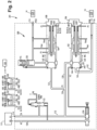
Fig. 1 is a schematic depiction of an engine fuel control system having a dual valve fuel metering system constructed in accordance with an embodiment of the present disclosure, showing primary and secondary flow paths with respective flow metering valves; and -
Fig. 2 is a schematic depiction of an engine fuel control system having another embodiment of a dual valve fuel metering system, showing a bypass pressure regulating valve. - Reference will now be made to the drawings wherein like reference numerals identify similar structural features or aspects of the subject disclosure. For purposes of explanation and illustration, and not limitation, a schematic view of an exemplary embodiment of a fuel pump system having a dual valve fuel metering system in accordance with the disclosure is shown in
Fig. 1 and is designated generally byreference character 100. Other embodiments of the fuel pump systems in accordance with the disclosure, or aspects thereof, are provided inFig. 2 as will be described. The systems and methods described herein use dual flow metering valves in parallel to allow independent control of fuel flow to engine "primary" and "secondary" fuel manifolds. - As shown in
Fig. 1 , an enginefuel control system 101 includes a dual valvefuel metering system 100. The engine fuel control system includes apressure setting pump 111 upstream from the dual valvefuel metering system 100. Anengine computer 110 is operatively coupled to the dual valvefuel metering system 100 to control the dual valvefuel metering system 100. Thepump 111 is a positive displacement pump, and/or a pressure-setting pump and provides fuel to afuel inlet 114 at a pressure P1. The dual valvefuel metering system 100 includes "primary" and "secondary"flow paths nozzles 124. The fuel manifolds/nozzles 124 are downstream from the dual valvefuel metering system 100. The dual valvefuel metering system 100 incorporates two separate flow metering valves, primaryflow metering valve 102 and secondaryflow metering valve 104, that will meter flow individually in a closed-loop enginefuel control system 101. This provides an advantage over traditional systems that only have one or two modes of operation. Embodiments of the present disclosure offer a simpler architecture than traditional systems that rely on splitting components downstream of a single, main metering valve. This reduces the number of subcomponents for the fuel metering unit. It is contemplated that the dual valvefuel metering system 100 can work with different pump/supply configurations, depending on the application. - With continued reference to
Fig. 1 , dual valvefuel metering system 100 includes a primary EHSV 107 connected toengine computer 110. The EHSV 107 is configured and adapted to receive a command from theengine computer 110 and to control a position of apiston 140 of the primaryflow metering valve 102. Dual valvefuel metering system 100 includes a secondary EHSV 109 connected toengine computer 110. The secondary EHSV 109 is configured and adapted to receive a command from theengine computer 110 and to control a position of apiston 140 of the secondaryflow metering valve 104. The primary andsecondary EHSVs engine computer 110.Primary EHSV 107 andsecondary EHSV 109 provide position control forpistons 140 of their respectiveflow metering valves engine computer 110. The dual valvefuel metering system 100 includes aflow path 112 at pressure P1 defined between afuel inlet 114 and two fuel outlets, a primary fuel outlet 116 (pressure PPRI) and a secondary fuel outlet 118 (pressure PSEC). Theflow path 112 includesprimary flow path 120 andsecondary flow path 122. Eachfuel outlet nozzles 124. - With continued reference to
Fig. 1 , primaryflow metering valve 102 is configured and adapted to meter flow on the primary flow path 120 (at pressure P1) fromfuel inlet 114 to primary fuel outlet 116 (at pressure PPRI). Secondaryflow metering valve 104 is configured and adapted to meter flow on thesecondary flow path 122. A primary pressure regulating valve (PRV) 126 is in fluid communication with the primaryflow metering valve 102. Thesystem 100 includes asecondary PRV 128 in fluid communication with the secondaryflow metering valve 104. The primary andsecondary PRV pressure locations respective valves PRV fuel inlet 114 with predictable metering accuracy. Thesystem 100 includes a servo PRV 132 (SPRV) upstream from asplit 134 between theprimary flow path 120 and thesecondary flow path 122.SPRV 132 is in fluid communication withflow path 112 and pressure (P1) and drain pressure (PD) throughdrain line 130.SPRV 132 provides a regulated pressure (PR) to theEHSVs EHSVs flow path 112 is free from valve or metering devices between theservo PRV 132 and thesplit 134. - As shown in
Fig. 1 ,system 100 includes a primary linear variable differential transformer (LVDT) 106 operatively connected to the primaryflow metering valve 102. Theprimary LVDT 106 is operatively coupled to theengine computer 110. Theprimary EHSV 107 is in electrical communication with theengine computer 110. Theengine computer 110 is electrically connected to theprimary LVDT 106 to receive a position of apiston 140 of the primaryflow metering valve 102 from theprimary LVDT 106. Theprimary EHSV 107 is operatively connected to theengine computer 110 to receive a current signal therefrom. The current signal is configured and adapted to control a position of thepiston 140 of the primaryflow metering valve 102, which acts to meter flow alongprimary flow path 120, shown schematically byarrow 148, fromfuel inlet 114 toprimary fuel outlet 116. The system includes asecondary LVDT 108 operatively connected to the secondaryflow metering valve 104. Thesecondary LVDT 108 is operatively coupled to theengine computer 110. Thesecondary EHSV 109 is in electrical communication with theengine computer 110. Theengine computer 110 is electrically connected to thesecondary LVDT 108 to receive a position of apiston 140 of the secondaryflow metering valve 104 from thesecondary LVDT 108. Thesecondary EHSV 109 is operatively connected to theengine computer 110 to receive a current signal therefrom. The current signal is configured and adapted to control a position of thepiston 140 of the secondaryflow metering valve 104, which acts to meter flow alongsecondary flow path 122, shown schematically byarrow 150, fromfuel inlet 114 tosecondary fuel outlet 118. EachEHSV engine computer 110 such that theengine computer 110 can constantly monitor thevalves respective LVDTs EHSVs - With continued reference to
Fig. 1 ,primary EHSV 107 andsecondary EHSV 109 each control the retract pressure (Pret) and the extend pressure (Pext) provided to their associated flow metering valves, primaryflow metering valve 102 and secondaryflow metering valve 104, respectively. Depending on the control from theEHSVs 108 and/or 109, thepistons 140 in eachflow metering valve flow metering valve 102 and the secondaryflow metering valve 104 are configured and adapted to together or each independently provide the fuel needed to a main gas generator 10 (fuel manifolds/nozzles 124 are part of the main gas generator 10) to provide the main thrust power. In this way, if one of thevalves - As shown in
Fig. 2 , an engine fuel control system 201 includes a dual valvefuel metering system 200. Engine fuel control system 201 is similar tosystem 101. Dual valvefuel metering system 200 is similar to dual valvefuel metering system 100.System 200 includes aflow path 112 defined between afuel inlet 114, and aprimary fuel outlet 116 andsecondary fuel outlet 118. Instead of the primaryfuel metering valve 102 having an in-line PRV 126,system 200 includes a bypass pressure regulating valve (BPRV) 226 in fluid communication with achamber 144 of the primaryflow metering valve 102. As shown inFig. 2 , theBPRV 226 has the ability to send some of the flow out viadrain line 130 in the event there is excess fluid inflow path 112. This is particularly significant for embodiments wherepump 111 is a positive displacement pump, as with a positive displacement pump there is no way to control the output volume. - The
BPRV 226 is configured and adapted to maintain a known delta pressure across thepressure locations metering valve 102 by bypassing any excess flow provided by apump 111, e.g. a positive displacement pump, back todrain line 130. In system 201, theBPRV 226 has pressure lines P1 and P2 located upstream of ashutoff face seal 152 offlow metering valve 102 to ensure drop-tight shutdown. - The methods and systems of the present disclosure, as described above and shown in the drawings, provide for dual valve fuel metering systems with superior properties including reduced complexity, and increased accuracy and controllability. Additionally, in the event of failure of one valve, the other can be sized to take over the functionality of both. The systems and methods of the present invention can apply to a variety of dual fuel pump systems, or the like. While the apparatus and methods of the subject disclosure have been shown and described with reference to preferred embodiments, those skilled in the art will readily appreciate that changes and/or modifications may be made thereto without departing from the scope of the invention as defined by the claims.
Claims (15)
- A dual valve fuel metering system comprising:a flow path defined between a fuel inlet (114) and a fuel outlet (116), wherein the flow path includes a primary flow path (120) and a secondary flow path (122), wherein the fuel outlet is configured and adapted to be in fluid communication with at least one engine fuel manifold;a primary flow metering valve (102) configured and adapted to meter flow on the primary flow path; anda secondary flow metering valve (104) configured and adapted to meter flow on the secondary flow path.
- The system as recited in claim 1, further comprising a primary linear variable differential transformer, LVDT, (106) operatively connected to the primary flow metering valve.
- The system as recited in claim 2, further comprising a primary electro-hydraulic servo valve, EHSV, (107) in fluid communication with the primary flow metering valve, wherein the primary EHSV is configured and adapted to control a position of a piston of the primary flow metering valve.
- The system as recited in any preceding claim, further comprising a secondary LVDT (108) operatively connected to the secondary flow metering valve.
- The system as recited in claim 4, further comprising a secondary EHSV (109) in fluid communication with the secondary flow metering valve, wherein the secondary EHSV is configured and adapted to control a position of a piston of the secondary flow metering valve.
- The system as recited in any preceding claim, a primary pressure regulating valve (126) in fluid communication with the primary flow metering valve, wherein the primary pressure regulating valve is configured and adapted to throttle excess pressure between an inlet of the primary flow metering valve and an outlet of the primary flow metering valve in order to maintain a known delta pressure.
- The system as recited in any preceding claim, a secondary pressure regulating valve (128) in fluid communication with the secondary flow metering valve, wherein the secondary pressure regulating valve is configured and adapted to throttle excess pressure between an inlet of the secondary flow metering valve and an outlet of the secondary flow metering valve in order to maintain a known delta pressure.
- The system as recited in any preceding claim, further comprising a servo pressure regulating valve (132) upstream from a split between the primary flow path and the secondary flow path.
- The system as recited in claim 8 , wherein the flow path is free from valve or metering devices between the servo pressure regulating valve and the split.
- The system as recited in any preceding claim, further comprising a bypass pressure regulating valve, BPRV, (226) in fluid communication with the primary flow metering valve, wherein the BPRV is configured and adapted to maintain a metering window delta pressure by bypassing any excess flow provided.
- The system as recited in any preceding claim, wherein the fuel outlet includes a primary fuel outlet in fluid communication with the primary flow path and a secondary fuel outlet in fluid communication with the secondary flow path.
- An engine fuel control system comprising:a pump (111);a dual valve fuel metering system (100) as claimed in any preceding claim, downstream from the pump;an engine downstream from the dual valve fuel metering system; andan engine computer (110) operatively coupled to the dual valve fuel metering system to control the dual valve fuel metering system.
- The system as recited in claim 12, wherein the pump is a positive displacement pump or wherein in the pump is a pressure-setting pump.
- The system as recited in claim 12 or 13, when dependent on claim 2, wherein the engine computer is in electrical communication with the primary LVDT to receive a position measurement of a piston of the primary flow metering valve from the primary LVDT.
- The system as recited in claim 12 or 13, when dependent on claim 2, wherein the engine computer is in electrical communication with the secondary LVDT to receive a position measurement of a piston of the secondary flow metering valve from the secondary LVDT.
Applications Claiming Priority (1)
| Application Number | Priority Date | Filing Date | Title |
|---|---|---|---|
| US17/827,344 US12146461B2 (en) | 2022-05-27 | 2022-05-27 | Dual valve fuel metering systems |
Publications (2)
| Publication Number | Publication Date |
|---|---|
| EP4283111A1 true EP4283111A1 (en) | 2023-11-29 |
| EP4283111B1 EP4283111B1 (en) | 2026-01-28 |
Family
ID=86609737
Family Applications (1)
| Application Number | Title | Priority Date | Filing Date |
|---|---|---|---|
| EP23176225.3A Active EP4283111B1 (en) | 2022-05-27 | 2023-05-30 | Dual valve fuel metering systems |
Country Status (2)
| Country | Link |
|---|---|
| US (1) | US12146461B2 (en) |
| EP (1) | EP4283111B1 (en) |
Families Citing this family (1)
| Publication number | Priority date | Publication date | Assignee | Title |
|---|---|---|---|---|
| US20250044816A1 (en) * | 2023-07-31 | 2025-02-06 | Hamilton Sundstrand Corporation | Valve systems |
Citations (4)
| Publication number | Priority date | Publication date | Assignee | Title |
|---|---|---|---|---|
| US20040011052A1 (en) * | 2002-07-18 | 2004-01-22 | Argo-Tech Corporation | Fuel delivery system |
| US8869509B2 (en) * | 2011-06-09 | 2014-10-28 | Woodward, Inc. | Accessory flow recovery system and method for thermal efficient pump and control system |
| US20150020889A1 (en) * | 2013-07-19 | 2015-01-22 | Woodward, Inc. | Series Plus Parallel Metering Pressure Regulation System for a Thermal Efficient Fuel Metering System |
| US20200123986A1 (en) * | 2018-10-17 | 2020-04-23 | Woodward, Inc. | Direct feedback regarding metered flow of fuel system |
Family Cites Families (15)
| Publication number | Priority date | Publication date | Assignee | Title |
|---|---|---|---|---|
| US3618777A (en) * | 1969-12-15 | 1971-11-09 | Chandler Evans Inc | Low-flow contaminated fuel transfer system for a fuel control |
| US5339636A (en) | 1992-12-04 | 1994-08-23 | United Technologies Corporation | Fuel splitter valve assembly for gas turbine |
| US5448882A (en) | 1993-12-14 | 1995-09-12 | United Technologies Corporation | Fuel metering system |
| US5809771A (en) * | 1996-01-19 | 1998-09-22 | Woodward Governor Company | Aircraft engine fuel system |
| US6381946B1 (en) | 2000-05-22 | 2002-05-07 | Woodward Governor Company | Two stage fuel metering system for gas turbine |
| US6619027B1 (en) | 2000-10-13 | 2003-09-16 | General Electric Company | Gas turbine having rotor overspeed and overboost protection |
| US6487847B1 (en) * | 2000-11-03 | 2002-12-03 | General Electric Company | Gas turbine engine fuel control system |
| US6637199B2 (en) | 2002-01-28 | 2003-10-28 | Woodward Governor Co. | Pressure switching valve for multiple redundant electrohydraulic servo valve systems |
| ATE500415T1 (en) * | 2007-11-05 | 2011-03-15 | Delphi Technologies Holding | METERING VALVES FOR FUEL INJECTION |
| US8893466B2 (en) | 2011-03-18 | 2014-11-25 | Hamilton Sundstrand Corporation | Dual pump fuel flow system for a gas turbine engine and method of controlling |
| EP2844874B1 (en) | 2012-05-01 | 2020-09-09 | Eaton Corporation | Hydromechanical pressure compensation control of a variable displacement pump in a centrifugal pumping and metering system and associated method |
| US9476358B2 (en) * | 2013-07-19 | 2016-10-25 | Woodward, Inc. | Parallel metering pressure regulation system for a thermal efficient metering system |
| WO2015077238A1 (en) * | 2013-11-20 | 2015-05-28 | Woodward, Inc. | Parallel metering pressure regulation system with integrated flow meter placement |
| US10968832B2 (en) * | 2016-11-17 | 2021-04-06 | Honeywell International Inc. | Combined overspeed and fuel stream selector systems |
| US11408347B2 (en) | 2019-07-22 | 2022-08-09 | Hamilton Sundstrand Corporation | Fuel systems |
-
2022
- 2022-05-27 US US17/827,344 patent/US12146461B2/en active Active
-
2023
- 2023-05-30 EP EP23176225.3A patent/EP4283111B1/en active Active
Patent Citations (4)
| Publication number | Priority date | Publication date | Assignee | Title |
|---|---|---|---|---|
| US20040011052A1 (en) * | 2002-07-18 | 2004-01-22 | Argo-Tech Corporation | Fuel delivery system |
| US8869509B2 (en) * | 2011-06-09 | 2014-10-28 | Woodward, Inc. | Accessory flow recovery system and method for thermal efficient pump and control system |
| US20150020889A1 (en) * | 2013-07-19 | 2015-01-22 | Woodward, Inc. | Series Plus Parallel Metering Pressure Regulation System for a Thermal Efficient Fuel Metering System |
| US20200123986A1 (en) * | 2018-10-17 | 2020-04-23 | Woodward, Inc. | Direct feedback regarding metered flow of fuel system |
Also Published As
| Publication number | Publication date |
|---|---|
| US20230383715A1 (en) | 2023-11-30 |
| EP4283111B1 (en) | 2026-01-28 |
| US12146461B2 (en) | 2024-11-19 |
Similar Documents
| Publication | Publication Date | Title |
|---|---|---|
| EP4063654A2 (en) | Variable displacement pump with active bypass feedback control | |
| EP1295021B1 (en) | Method and apparatus for providing shutoff, overspeed protection, and directional control of a bypass flow in a fuel delivery system | |
| US6981359B2 (en) | Centrifugal pump fuel system and method for gas turbine engine | |
| US9470152B2 (en) | Engine fuel control system | |
| US8464740B2 (en) | Combustor fuel control systems with flow divider assemblies | |
| US11788476B1 (en) | Fluid system with variable pump discharge pressure and method | |
| EP4283111B1 (en) | Dual valve fuel metering systems | |
| US4591317A (en) | Dual pump controls | |
| EP4390127A1 (en) | Pumps with backup capability | |
| US20050072160A1 (en) | Method and system for fuel control in a gas turbine engine | |
| EP4382747B1 (en) | Variable displacement pump with flow delivery to different systems with different pressure schedules | |
| EP4400719A1 (en) | Direct control for variable displacement pumps | |
| EP4400720B1 (en) | High turn down ratio direct control for variable displacement pumps with flow sensing | |
| US5501245A (en) | Coaxial pressurized fluid flow regulator | |
| US12071899B2 (en) | Pump system for a gas turbine engine | |
| EP2025933B1 (en) | Dual mode compensation for variable displacement pump metering system | |
| US20240392774A1 (en) | Active displacement control against temperature target | |
| US12398682B1 (en) | Direct control variable displacement pump with dual-function high-pressure relief valve- pressure regulating valve | |
| US11781483B1 (en) | Minimum pressure valve for aircraft fuel system | |
| US20240392773A1 (en) | Direct controlled variable displacement valves with dual set point pressure relief | |
| US20240350722A1 (en) | Electrically direct controlled variable displacement pumps | |
| US20240392728A1 (en) | Direct control variable displacement metering pumps |
Legal Events
| Date | Code | Title | Description |
|---|---|---|---|
| PUAI | Public reference made under article 153(3) epc to a published international application that has entered the european phase |
Free format text: ORIGINAL CODE: 0009012 |
|
| STAA | Information on the status of an ep patent application or granted ep patent |
Free format text: STATUS: THE APPLICATION HAS BEEN PUBLISHED |
|
| AK | Designated contracting states |
Kind code of ref document: A1 Designated state(s): AL AT BE BG CH CY CZ DE DK EE ES FI FR GB GR HR HU IE IS IT LI LT LU LV MC ME MK MT NL NO PL PT RO RS SE SI SK SM TR |
|
| STAA | Information on the status of an ep patent application or granted ep patent |
Free format text: STATUS: REQUEST FOR EXAMINATION WAS MADE |
|
| 17P | Request for examination filed |
Effective date: 20240529 |
|
| RBV | Designated contracting states (corrected) |
Designated state(s): AL AT BE BG CH CY CZ DE DK EE ES FI FR GB GR HR HU IE IS IT LI LT LU LV MC ME MK MT NL NO PL PT RO RS SE SI SK SM TR |
|
| GRAP | Despatch of communication of intention to grant a patent |
Free format text: ORIGINAL CODE: EPIDOSNIGR1 |
|
| STAA | Information on the status of an ep patent application or granted ep patent |
Free format text: STATUS: GRANT OF PATENT IS INTENDED |
|
| INTG | Intention to grant announced |
Effective date: 20250821 |
|
| GRAS | Grant fee paid |
Free format text: ORIGINAL CODE: EPIDOSNIGR3 |
|
| GRAA | (expected) grant |
Free format text: ORIGINAL CODE: 0009210 |
|
| STAA | Information on the status of an ep patent application or granted ep patent |
Free format text: STATUS: THE PATENT HAS BEEN GRANTED |
|
| AK | Designated contracting states |
Kind code of ref document: B1 Designated state(s): AL AT BE BG CH CY CZ DE DK EE ES FI FR GB GR HR HU IE IS IT LI LT LU LV MC ME MK MT NL NO PL PT RO RS SE SI SK SM TR |
|
| REG | Reference to a national code |
Ref country code: CH Ref legal event code: F10 Free format text: ST27 STATUS EVENT CODE: U-0-0-F10-F00 (AS PROVIDED BY THE NATIONAL OFFICE) Effective date: 20260128 Ref country code: GB Ref legal event code: FG4D |
|
| REG | Reference to a national code |
Ref country code: DE Ref legal event code: R096 Ref document number: 602023011174 Country of ref document: DE |
|
| REG | Reference to a national code |
Ref country code: IE Ref legal event code: FG4D |