EP4283103A1 - Dual pump fuel systems - Google Patents
Dual pump fuel systems Download PDFInfo
- Publication number
- EP4283103A1 EP4283103A1 EP23175680.0A EP23175680A EP4283103A1 EP 4283103 A1 EP4283103 A1 EP 4283103A1 EP 23175680 A EP23175680 A EP 23175680A EP 4283103 A1 EP4283103 A1 EP 4283103A1
- Authority
- EP
- European Patent Office
- Prior art keywords
- fuel pump
- fuel
- support
- outlet
- pump
- Prior art date
- Legal status (The legal status is an assumption and is not a legal conclusion. Google has not performed a legal analysis and makes no representation as to the accuracy of the status listed.)
- Pending
Links
- 239000000446 fuel Substances 0.000 title claims abstract description 259
- 230000009977 dual effect Effects 0.000 title claims description 8
- 239000012530 fluid Substances 0.000 claims abstract description 43
- 238000004891 communication Methods 0.000 claims abstract description 33
- 230000001105 regulatory effect Effects 0.000 claims abstract description 6
- 238000000034 method Methods 0.000 claims description 21
- 238000006073 displacement reaction Methods 0.000 claims description 15
- 238000005086 pumping Methods 0.000 claims description 8
- 238000011144 upstream manufacturing Methods 0.000 claims description 7
- 230000001276 controlling effect Effects 0.000 claims description 3
- 238000013461 design Methods 0.000 description 2
- 238000000605 extraction Methods 0.000 description 2
- 238000009877 rendering Methods 0.000 description 2
- 230000001052 transient effect Effects 0.000 description 2
- 230000000712 assembly Effects 0.000 description 1
- 238000000429 assembly Methods 0.000 description 1
- 238000007796 conventional method Methods 0.000 description 1
- 238000012986 modification Methods 0.000 description 1
- 230000004048 modification Effects 0.000 description 1
- 230000003071 parasitic effect Effects 0.000 description 1
- 239000013589 supplement Substances 0.000 description 1
Images



Classifications
-
- F—MECHANICAL ENGINEERING; LIGHTING; HEATING; WEAPONS; BLASTING
- F02—COMBUSTION ENGINES; HOT-GAS OR COMBUSTION-PRODUCT ENGINE PLANTS
- F02C—GAS-TURBINE PLANTS; AIR INTAKES FOR JET-PROPULSION PLANTS; CONTROLLING FUEL SUPPLY IN AIR-BREATHING JET-PROPULSION PLANTS
- F02C7/00—Features, components parts, details or accessories, not provided for in, or of interest apart form groups F02C1/00 - F02C6/00; Air intakes for jet-propulsion plants
- F02C7/22—Fuel supply systems
- F02C7/236—Fuel delivery systems comprising two or more pumps
-
- F—MECHANICAL ENGINEERING; LIGHTING; HEATING; WEAPONS; BLASTING
- F02—COMBUSTION ENGINES; HOT-GAS OR COMBUSTION-PRODUCT ENGINE PLANTS
- F02C—GAS-TURBINE PLANTS; AIR INTAKES FOR JET-PROPULSION PLANTS; CONTROLLING FUEL SUPPLY IN AIR-BREATHING JET-PROPULSION PLANTS
- F02C9/00—Controlling gas-turbine plants; Controlling fuel supply in air- breathing jet-propulsion plants
- F02C9/26—Control of fuel supply
- F02C9/263—Control of fuel supply by means of fuel metering valves
-
- F—MECHANICAL ENGINEERING; LIGHTING; HEATING; WEAPONS; BLASTING
- F04—POSITIVE - DISPLACEMENT MACHINES FOR LIQUIDS; PUMPS FOR LIQUIDS OR ELASTIC FLUIDS
- F04B—POSITIVE-DISPLACEMENT MACHINES FOR LIQUIDS; PUMPS
- F04B23/00—Pumping installations or systems
- F04B23/04—Combinations of two or more pumps
-
- F—MECHANICAL ENGINEERING; LIGHTING; HEATING; WEAPONS; BLASTING
- F04—POSITIVE - DISPLACEMENT MACHINES FOR LIQUIDS; PUMPS FOR LIQUIDS OR ELASTIC FLUIDS
- F04B—POSITIVE-DISPLACEMENT MACHINES FOR LIQUIDS; PUMPS
- F04B49/00—Control, e.g. of pump delivery, or pump pressure of, or safety measures for, machines, pumps, or pumping installations, not otherwise provided for, or of interest apart from, groups F04B1/00 - F04B47/00
- F04B49/22—Control, e.g. of pump delivery, or pump pressure of, or safety measures for, machines, pumps, or pumping installations, not otherwise provided for, or of interest apart from, groups F04B1/00 - F04B47/00 by means of valves
- F04B49/225—Control, e.g. of pump delivery, or pump pressure of, or safety measures for, machines, pumps, or pumping installations, not otherwise provided for, or of interest apart from, groups F04B1/00 - F04B47/00 by means of valves with throttling valves or valves varying the pump inlet opening or the outlet opening
-
- F—MECHANICAL ENGINEERING; LIGHTING; HEATING; WEAPONS; BLASTING
- F02—COMBUSTION ENGINES; HOT-GAS OR COMBUSTION-PRODUCT ENGINE PLANTS
- F02C—GAS-TURBINE PLANTS; AIR INTAKES FOR JET-PROPULSION PLANTS; CONTROLLING FUEL SUPPLY IN AIR-BREATHING JET-PROPULSION PLANTS
- F02C7/00—Features, components parts, details or accessories, not provided for in, or of interest apart form groups F02C1/00 - F02C6/00; Air intakes for jet-propulsion plants
- F02C7/22—Fuel supply systems
-
- F—MECHANICAL ENGINEERING; LIGHTING; HEATING; WEAPONS; BLASTING
- F23—COMBUSTION APPARATUS; COMBUSTION PROCESSES
- F23R—GENERATING COMBUSTION PRODUCTS OF HIGH PRESSURE OR HIGH VELOCITY, e.g. GAS-TURBINE COMBUSTION CHAMBERS
- F23R3/00—Continuous combustion chambers using liquid or gaseous fuel
- F23R3/28—Continuous combustion chambers using liquid or gaseous fuel characterised by the fuel supply
Definitions
- the present disclosure relates to dual pump fuel systems and more particularly to valve assemblies for dual pump fuel systems.
- Fuel pump systems generally include a single positive displacement pump, where the single pump is sized to provide the desired fuel flow under a variety of conditions, e.g. take-off and cruise. That single pump is sized to provide flow on-demand for large transient or short-term high-power conditions, which can be inefficient when most of the time the system is at cruise, which tends to be longer in duration but with a much lower flow demand than a higher-power condition.
- a fuel pump system includes a main fuel pump between a system fuel inlet and a system fuel outlet.
- the system includes a fuel flow path at least partially defined between the main fuel pump and the system fuel outlet.
- the system includes a support fuel pump between the system fuel inlet and the system fuel outlet.
- the support fuel pump is sized to provide more flow to the system fuel outlet, when in an active state, than the main fuel pump.
- the system includes a valve assembly in fluid communication with the support fuel pump configured and adapted to connect the support fuel pump to the system fuel outlet.
- the system includes a pressure regulating valve (PRV) in fluid communication with the fuel flow path between the main fuel pump and the system fuel outlet.
- the system includes an electro-hydraulic servo valve (EHSV) in fluid communication with the fuel flow path between the PRV and the system fuel outlet.
- the valve assembly includes a pressure bypass valve (PBV) in fluid communication with the fuel flow path, between the support fuel pump and the system fuel outlet.
- PBV pressure bypass valve
- the system can include a solenoid valve in fluid communication with the PBV.
- the PBV can be configured and adapted to translate between an open position and a closed position. In the open position, fluid flow can be permitted between the support fuel pump and the system fuel outlet.
- the valve assembly includes a second PRV in fluid communication with the support fuel pump.
- the PRV can be positioned between an upstream side and a downstream side of the support fuel pump.
- the valve assembly can include a solenoid valve in fluid communication with the upstream side of the support fuel pump and the downstream side of the support fuel pump.
- the valve assembly can include a second EHSV in fluid communication with the support fuel pump between the support fuel pump and The fuel pump system fuel outlet.
- the system includes a shut-off valve (SOV) in fluid communication with the support fuel pump between the support fuel pump and the system fuel outlet.
- SOV shut-off valve
- the SOV can be configured and adapted to translate between and open position and a closed position. In the open position, fluid flow can be permitted between the support fuel pump and the system fuel outlet.
- the main fuel pump and the support fuel pump can be fixed displacement, positive displacement pumps.
- a method for controlling a dual fuel pump system includes pumping fuel from a system fuel inlet to a system fuel outlet with a main fuel pump.
- the method includes at least one of connecting or disconnecting a support fuel pump with a valve assembly.
- the method includes pumping fuel from the system fuel inlet to the system fuel outlet with a support fuel pump.
- the support fuel pump is sized to provide more flow to the system fuel outlet than the main fuel pump.
- the method can include switching at least one of the solenoid or the EHSV to a closed position to close the valve assembly to place the support fuel pump in an idle state.
- the valve assembly can include at least one of the PRV, the PBV, or the SOV to place the support fuel pump in an idle state.
- the method can include switching the EHSV to a closed position to close at least one of the PRV, the PBV, or the SOV to place the support fuel pump in an idle state.
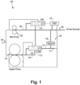
- Fig. 1 a schematic view of an exemplary embodiment of the fuel pump system in accordance with the disclosure is shown in Fig. 1 and is designated generally by reference character 100.
- Other embodiments of the fuel pump systems in accordance with the disclosure, or aspects thereof, are provided in Figs. 2-6 as will be described.
- the systems and methods described herein use dual positive displacement pumps in an "on demand" configuration where the second pump (the support pump) can be put into an idle mode to reduce pump horsepower at critical operating conditions.
- fuel pump system 100 includes two fixed displacement, positive displacement pumps.
- a first of the two fixed displacement, positive displacement pumps is a main fuel pump 102 between a system fuel inlet 104 and a system fuel outlet 106.
- the system 100 includes a fuel flow path 108 at least partially defined between the main fuel pump 102 and the system fuel outlet 106.
- the system 100 includes a support fuel pump 110 between the system fuel inlet 104 and the system fuel outlet 106.
- the main fuel pump 102 is sized to provide just enough flow to satisfy a critical design point (typically cruise) and a second larger pump (the support fuel pump) that can be selected to provide flow on-demand for large transient or short-term high-power conditions.
- System 100 is also more efficient (in terms of horsepower extraction at cruise/design point and reduction in heat added to fuel from pumping) than traditional single positive displacement pump systems where the single pump is sized to provide combined flow of the two fixed displacement pumps. Although, this may come at an increase in cost and weight and reduction in reliability, these negative characteristics can be outweighed depending on engine trade factors.
- support fuel pump 110 when in an active state, is sized to provide more flow to the system fuel outlet 106 than the main fuel pump 102.
- the system 100 includes a valve assembly 101 in fluid communication with the support fuel pump 110 configured and adapted to connect the support fuel pump 110 to the system fuel outlet 106.
- the valve assembly 101 includes a pressure bypass valve (PBV 112) in fluid communication with the fuel flow path 108, between the support fuel pump 110 and the system fuel outlet 106.
- the valve assembly 101 includes a solenoid valve 120 in fluid communication with the PBV 112.
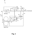
- the PBV 112 is configured and adapted to translate between a closed position (shown in Fig. 1 ) and an open position (shown in Fig. 2 ).
- support fuel pump 110 is placed in an idle state (typically during cruise) by a pump bypass valve (PBV 112).
- PBV 112 pump bypass valve
- line 115 and a right hand pressure inlet 137 of the PBV 112 have the same pressure as idle pressure 139 at high pressure inlet 138 of the PBV 112 such that a flow path between inlet 130 and outlet 132 is closed.
- a pressure differential (dP) between a low pressure (indicated schematically by the thinner lines) and a high pressure (HP) (indicated schematically by the thicker lines) is set by system resistances and/or an orifice 117 to minimize high pressure when idled.
- dP pressure differential
- HP high pressure
- the support fuel pump 110 is commanded on via a command by solenoid 120 to provide the low unit inlet pressure to line 115 (now shown as a thinner line than Fig. 1 ) and a right hand pressure inlet 137 of the PBV 112 such that a support pump idle pressure 139 at high pressure inlet 138 of the PBV 112 shifts the valve spool of the PBV to the right (as oriented in Fig. 2 ) and opens the PBV 112 so that the support fuel pump 110 can provide fuel flow to the fuel flow path 108 and supplement that provided by the main fuel pump 102.
- the system 100 includes a pressure regulating valve (PRV) 116 in fluid communication with the fuel flow path 108 between the main fuel pump 102 and the system fuel outlet 106.
- the PRV 116 is positioned between a downstream side 136 and an upstream side 134 of the support fuel pump 110.
- the system 100 includes electro-hydraulic servo valve (EHSV) 118 in fluid communication with the fuel flow path 108 between the PRV 116 and the system fuel outlet 106.
- EHSV electro-hydraulic servo valve
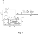
- valve assembly 201 As shown in Figs. 3-4 , another embodiment of a fuel pump system 200 is shown.
- System 200 similar to system 100 except that a valve assembly 201 system 200 includes a second PRV 226 in fluid communication with a support fuel pump 210 and a shut-off valve (SOV) 228, instead of PBV 112.
- valve assembly 201 includes a solenoid valve 220 in fluid communication with the downstream side 236 of the support fuel pump 210 and the upstream side 234 of the support fuel pump 210.
- Support fuel pump 210 is placed in an idle state (typically during cruise) by a shut off valve (SOV) 228. This idle state is shown in Fig. 3 .
- SOV shut off valve
- fuel line 215 has a lower pressure than idle pressure at high pressure inlet 238 of the PBV 112 such that a flow path between inlet 240 and outlet 242 is open.
- the PRV sets a fixed low differential pressure (dP) between a low pressure (a unit inlet pressure, indicated schematically by the thinner lines) and a high pressure (HP) (a pump idle pressure, indicated schematically by the thicker lines) to minimize HP when idled.
- support pump 210 is placed in an idle state by solenoid 220 which controls SOV 228 and PRV 226.
- the solenoid 220 is switched to close the PRV 226 and open the SOV 228 so that the secondary pump 210 can assist the primary 202.
- the support fuel pump 210 is commanded on via a command by solenoid 220 that provides a support pump idle pressure 239 (indicated schematically by thicker lines) to an inlet 237 of the SOV 228. With the higher support pump idle pressure 239 at inlet 237, valve spool of the SOV 228 is driven to the right (as oriented in Fig. 4 ).
- the support pump idle pressure 239 from solenoid 220 drives the spool of the PRV 226 to the left closing the flow path from PRV inlet 240 to PRV outlet 242.
- SOV 228 is in fluid communication with the support fuel pump 210 between the support fuel pump 210 and the system fuel outlet 206.
- the SOV 228 is configured and adapted to translate between and open position and a closed position. In the open position, shown in Fig. 3 , fluid flow is permitted between the support fuel pump 210 and the system fuel outlet 206.
- the main fuel pump 202 and the support fuel pump 210 are fixed displacement, positive displacement pumps.
- the system 200 includes a pressure regulating valve (PRV) 216 in fluid communication with the fuel flow path 208 between the main fuel pump 202 and the system fuel outlet 206.
- the system 200 includes electro-hydraulic servo valve (EHSV) 218 similar to EHSV 118.
- EHSV electro-hydraulic servo valve
- the system 300 includes a pressure regulating valve (PRV) 316 in fluid communication with the fuel flow path 308 between a main fuel pump 302 and a system fuel outlet 306.
- the system 300 includes electro-hydraulic servo valve (EHSV) 318 similar to EHSV 118.
- Fuel pump system 300 is similar to system 200 except that instead of a solenoid control, e.g., solenoid 120 or 220, pump 310 is placed in an idle state by a uni-polar EHSV 320 which controls a SOV 328.
- the EHSV 320 is fluid communication with a support fuel pump 310 between the support fuel pump 310 and a fuel pump system fuel outlet 306.
- System 300 includes a main fuel pump 302 between a system fuel inlet 304 and a system fuel outlet 306.
- the system 300 includes a fuel flow path 308 at least partially defined between the main fuel pump 302 and the system fuel outlet 306.
- Shut-off valve 328 is in fluid communication with the support fuel pump 310 between the support fuel pump 310 and the system fuel outlet 306.
- SOV 328 is configured and adapted to translate between and closed position (in Fig. 5 ) and an open position (in Fig. 6 ).
- open position fluid flow is permitted between the support fuel pump 310 and the system fuel outlet 306.
- open position fluid flow is permitted to flow through an inlet 330 of the SOV 328 to an outlet 332 of the SOV 328 between the support fuel pump 310 and the system fuel outlet 306.
- the PRV 326 is positioned between a downstream side 336 and an upstream side 334 of the support fuel pump 310.
- the closed position fluid flow is not permitted from inlet 330 to outlet 332 of SOV 328, thereby rendering the support fuel pump 310 in an idle state.
- support fuel pump 310 is placed in an idle state (typically during cruise) by a shut off valve 328. This state is shown in Fig. 5 .
- a pressure differential (dP) between a low pressure (a unit inlet pressure, indicated schematically by the thinner lines) and a high pressure (HP) (pump idle pressure, indicated schematically by the thicker lines) is set by system resistances and/or an orifice 317 to minimize high pressure when idled.
- the support fuel pump 310 is commanded on via a command by EHSV 320 that provides the unit inlet low pressure in line 315 to an inlet 337 of the SOV 328.
- a support pump idle pressure 339 drives the valve spool of the SOV 328 to the right (as oriented in Fig. 6 ).
- EHSV 320 drives the spool of the PRV 326 to the left closing the flow path from PRV inlet 340 and PRV outlet 342.
- the PRV 326 sets a dP that is controlled by the PRV 326 to minimize HP throughout the idling envelope, similar to system 200 described above.
- the EHSV 320 is depowered/set to a low current to close the PRV 326 (shown in Fig. 6 ) and the EHSVs 5th control port sends low pressure to open the SOV 328 so that the support fuel pump 310 can assist the primary 302.
- a method for controlling a dual fuel pump system includes pumping fuel from a system fuel inlet, e.g. system fuel inlet 104, 204, 304, to a system fuel outlet, e.g., 106, 206, or 306, with a main fuel pump, e.g. main fuel pump 102, 202 or 302.
- the method includes opening at least one of a valve assembly, e.g. valve assembly 101, 201, or 301, with at least one of a solenoid, e.g. solenoid 120 or 220, or an EHSV, e.g. EHSV 320.
- the method includes pumping fuel from the system fuel inlet to the system fuel outlet with a support fuel pump, e.g. support fuel pump 110, 210, or 310.
- the support fuel pump is sized to provide more flow to the system fuel outlet than the main fuel pump.
- the method includes switching a solenoid, e.g. the solenoid 120, to a closed position to close the PBV, e.g. the PBV 112, to place the support fuel pump in an idle state.
- the method includes switching a solenoid, e.g. a solenoid 220, to a closed position to open an SOV, and to close a PRV, e.g. the PRV 226, to place the support fuel pump in an idle state.
- the method includes switching an EHSV, e.g. an EHSV 320, to a closed position to open an SOV, e.g. the SOV 328, and to close a PRV, e.g. the PRV 326, to place the support fuel pump in an idle state.
- EHSV e.g. an EHSV 320
- PRV e.g. the PRV 326
Landscapes
- Engineering & Computer Science (AREA)
- Mechanical Engineering (AREA)
- General Engineering & Computer Science (AREA)
- Chemical & Material Sciences (AREA)
- Combustion & Propulsion (AREA)
- Fuel-Injection Apparatus (AREA)
Abstract
Description
- The present disclosure relates to dual pump fuel systems and more particularly to valve assemblies for dual pump fuel systems.
- Modem turbine engines are constantly attempting to reduce parasitic draw from control components to improve Thrust Specific Fuel Consumption (TSFC), while balancing cost, weight and reliability. Fuel pump systems generally include a single positive displacement pump, where the single pump is sized to provide the desired fuel flow under a variety of conditions, e.g. take-off and cruise. That single pump is sized to provide flow on-demand for large transient or short-term high-power conditions, which can be inefficient when most of the time the system is at cruise, which tends to be longer in duration but with a much lower flow demand than a higher-power condition.
- The conventional techniques have been considered satisfactory for their intended purpose. However, there is a need for improved fuel pump systems. This disclosure provides a solution for this need.
- A fuel pump system includes a main fuel pump between a system fuel inlet and a system fuel outlet. The system includes a fuel flow path at least partially defined between the main fuel pump and the system fuel outlet. The system includes a support fuel pump between the system fuel inlet and the system fuel outlet. The support fuel pump is sized to provide more flow to the system fuel outlet, when in an active state, than the main fuel pump. The system includes a valve assembly in fluid communication with the support fuel pump configured and adapted to connect the support fuel pump to the system fuel outlet. The system includes a pressure regulating valve (PRV) in fluid communication with the fuel flow path between the main fuel pump and the system fuel outlet. The system includes an electro-hydraulic servo valve (EHSV) in fluid communication with the fuel flow path between the PRV and the system fuel outlet.
- In some embodiments, the valve assembly includes a pressure bypass valve (PBV) in fluid communication with the fuel flow path, between the support fuel pump and the system fuel outlet. The system can include a solenoid valve in fluid communication with the PBV. The PBV can be configured and adapted to translate between an open position and a closed position. In the open position, fluid flow can be permitted between the support fuel pump and the system fuel outlet.
- In some embodiments, the valve assembly includes a second PRV in fluid communication with the support fuel pump. The PRV can be positioned between an upstream side and a downstream side of the support fuel pump. The valve assembly can include a solenoid valve in fluid communication with the upstream side of the support fuel pump and the downstream side of the support fuel pump. The valve assembly can include a second EHSV in fluid communication with the support fuel pump between the support fuel pump and The fuel pump system fuel outlet.
- In some embodiments, the system includes a shut-off valve (SOV) in fluid communication with the support fuel pump between the support fuel pump and the system fuel outlet. The SOV can be configured and adapted to translate between and open position and a closed position. In the open position, fluid flow can be permitted between the support fuel pump and the system fuel outlet. The main fuel pump and the support fuel pump can be fixed displacement, positive displacement pumps.
- In accordance with another aspect, a method for controlling a dual fuel pump system includes pumping fuel from a system fuel inlet to a system fuel outlet with a main fuel pump. The method includes at least one of connecting or disconnecting a support fuel pump with a valve assembly. The method includes pumping fuel from the system fuel inlet to the system fuel outlet with a support fuel pump. The support fuel pump is sized to provide more flow to the system fuel outlet than the main fuel pump.
- The method can include switching at least one of the solenoid or the EHSV to a closed position to close the valve assembly to place the support fuel pump in an idle state. The valve assembly can include at least one of the PRV, the PBV, or the SOV to place the support fuel pump in an idle state. The method can include switching the EHSV to a closed position to close at least one of the PRV, the PBV, or the SOV to place the support fuel pump in an idle state.
- These and other features of the systems and methods of the subject disclosure will become more readily apparent to those skilled in the art from the following detailed description of the preferred embodiments taken in conjunction with the drawings.
- So that those skilled in the art to which the subject disclosure appertains will readily understand how to make and use the devices and methods of the subject disclosure without undue experimentation, preferred embodiments thereof will be described in detail herein below with reference to certain figures, wherein:
-
Fig. 1 is a schematic depiction of a fuel pump system constructed in accordance with an embodiment of the present disclosure, showing the PBV in a closed position; -
Fig. 2 is a schematic depiction of the system ofFig. 1 , showing the PBV in an open position; -
Fig. 3 is a schematic depiction of a fuel pump system constructed in accordance with another embodiment of the present disclosure, showing the SOV in a closed position; -
Fig. 4 is a schematic depiction of the system ofFig. 3 , showing the SOV in an open position; -
Fig. 5 is a schematic depiction of a fuel pump system constructed in accordance with another embodiment of the present disclosure, showing the SOV in a closed position; and -
Fig. 6 is a schematic depiction of the system ofFig. 3 , showing the SOV in an open position. - Reference will now be made to the drawings wherein like reference numerals identify similar structural features or aspects of the subject disclosure. For purposes of explanation and illustration, and not limitation, a schematic view of an exemplary embodiment of the fuel pump system in accordance with the disclosure is shown in
Fig. 1 and is designated generally byreference character 100. Other embodiments of the fuel pump systems in accordance with the disclosure, or aspects thereof, are provided inFigs. 2-6 as will be described. The systems and methods described herein use dual positive displacement pumps in an "on demand" configuration where the second pump (the support pump) can be put into an idle mode to reduce pump horsepower at critical operating conditions. - As shown in
Figs. 1-2 ,fuel pump system 100 includes two fixed displacement, positive displacement pumps. A first of the two fixed displacement, positive displacement pumps is amain fuel pump 102 between asystem fuel inlet 104 and asystem fuel outlet 106. Thesystem 100 includes afuel flow path 108 at least partially defined between themain fuel pump 102 and thesystem fuel outlet 106. Thesystem 100 includes asupport fuel pump 110 between thesystem fuel inlet 104 and thesystem fuel outlet 106. Themain fuel pump 102 is sized to provide just enough flow to satisfy a critical design point (typically cruise) and a second larger pump (the support fuel pump) that can be selected to provide flow on-demand for large transient or short-term high-power conditions. By using two differently sized pumps that can be selected to provide on-demand fuel flow, the pump power draw at a critical condition (e.g., cruise) is reduced, because themain fuel pump 102 is right sized for that condition and thesupport fuel pump 110 is put into a minimum (idle) power condition.System 100 is also more efficient (in terms of horsepower extraction at cruise/design point and reduction in heat added to fuel from pumping) than traditional single positive displacement pump systems where the single pump is sized to provide combined flow of the two fixed displacement pumps. Although, this may come at an increase in cost and weight and reduction in reliability, these negative characteristics can be outweighed depending on engine trade factors. - With continued reference to
Figs. 1-2 , when in an active state, supportfuel pump 110 is sized to provide more flow to thesystem fuel outlet 106 than themain fuel pump 102. Thesystem 100 includes avalve assembly 101 in fluid communication with thesupport fuel pump 110 configured and adapted to connect thesupport fuel pump 110 to thesystem fuel outlet 106. Thevalve assembly 101 includes a pressure bypass valve (PBV 112) in fluid communication with thefuel flow path 108, between thesupport fuel pump 110 and thesystem fuel outlet 106. Thevalve assembly 101 includes asolenoid valve 120 in fluid communication with thePBV 112. ThePBV 112 is configured and adapted to translate between a closed position (shown inFig. 1 ) and an open position (shown inFig. 2 ). In the open position, fluid flow is permitted to flow through aninlet 130 of the PBV to anoutlet 132 of the PBV between thesupport fuel pump 110 and thesystem fuel outlet 106. In the closed position, fluid flow is not permitted frominlet 130 tooutlet 132, thereby rendering thesupport fuel pump 110 in an idle state. - With continued reference to
Figs. 1 and2 ,support fuel pump 110 is placed in an idle state (typically during cruise) by a pump bypass valve (PBV 112). This state is shown inFig. 1 . InFig. 1 ,line 115 and a righthand pressure inlet 137 of thePBV 112 have the same pressure asidle pressure 139 athigh pressure inlet 138 of thePBV 112 such that a flow path betweeninlet 130 andoutlet 132 is closed. A pressure differential (dP) between a low pressure (indicated schematically by the thinner lines) and a high pressure (HP) (indicated schematically by the thicker lines) is set by system resistances and/or anorifice 117 to minimize high pressure when idled. As shown inFig. 2 , thesupport fuel pump 110 is commanded on via a command bysolenoid 120 to provide the low unit inlet pressure to line 115 (now shown as a thinner line thanFig. 1 ) and a righthand pressure inlet 137 of thePBV 112 such that a support pumpidle pressure 139 athigh pressure inlet 138 of thePBV 112 shifts the valve spool of the PBV to the right (as oriented inFig. 2 ) and opens thePBV 112 so that thesupport fuel pump 110 can provide fuel flow to thefuel flow path 108 and supplement that provided by themain fuel pump 102. - With continued reference to
Figs. 1-2 , thesystem 100 includes a pressure regulating valve (PRV) 116 in fluid communication with thefuel flow path 108 between themain fuel pump 102 and thesystem fuel outlet 106. ThePRV 116 is positioned between adownstream side 136 and anupstream side 134 of thesupport fuel pump 110. Thesystem 100 includes electro-hydraulic servo valve (EHSV) 118 in fluid communication with thefuel flow path 108 between thePRV 116 and thesystem fuel outlet 106. - As shown in
Figs. 3-4 , another embodiment of afuel pump system 200 is shown.System 200 similar tosystem 100 except that avalve assembly 201system 200 includes asecond PRV 226 in fluid communication with asupport fuel pump 210 and a shut-off valve (SOV) 228, instead ofPBV 112. Additionally,valve assembly 201 includes asolenoid valve 220 in fluid communication with thedownstream side 236 of thesupport fuel pump 210 and theupstream side 234 of thesupport fuel pump 210.Support fuel pump 210 is placed in an idle state (typically during cruise) by a shut off valve (SOV) 228. This idle state is shown inFig. 3 . InFig. 3 ,fuel line 215 has a lower pressure than idle pressure athigh pressure inlet 238 of thePBV 112 such that a flow path betweeninlet 240 andoutlet 242 is open. The PRV sets a fixed low differential pressure (dP) between a low pressure (a unit inlet pressure, indicated schematically by the thinner lines) and a high pressure (HP) (a pump idle pressure, indicated schematically by the thicker lines) to minimize HP when idled. - With continued to
Figs. 3-4 ,support pump 210 is placed in an idle state bysolenoid 220 which controls SOV 228 andPRV 226. Thesolenoid 220 is switched to close thePRV 226 and open the SOV 228 so that thesecondary pump 210 can assist the primary 202. Thesupport fuel pump 210 is commanded on via a command bysolenoid 220 that provides a support pump idle pressure 239 (indicated schematically by thicker lines) to aninlet 237 of the SOV 228. With the higher support pumpidle pressure 239 atinlet 237, valve spool of the SOV 228 is driven to the right (as oriented inFig. 4 ). The support pumpidle pressure 239 fromsolenoid 220 drives the spool of thePRV 226 to the left closing the flow path fromPRV inlet 240 toPRV outlet 242. - With continued to
Figs. 3-4 , SOV 228 is in fluid communication with thesupport fuel pump 210 between thesupport fuel pump 210 and thesystem fuel outlet 206. The SOV 228 is configured and adapted to translate between and open position and a closed position. In the open position, shown inFig. 3 , fluid flow is permitted between thesupport fuel pump 210 and thesystem fuel outlet 206. Themain fuel pump 202 and thesupport fuel pump 210 are fixed displacement, positive displacement pumps. Similar tosystem 100, thesystem 200 includes a pressure regulating valve (PRV) 216 in fluid communication with thefuel flow path 208 between themain fuel pump 202 and thesystem fuel outlet 206. Thesystem 200 includes electro-hydraulic servo valve (EHSV) 218 similar toEHSV 118. - As shown in
Figs. 5-6 , similar tosystem 100, thesystem 300 includes a pressure regulating valve (PRV) 316 in fluid communication with thefuel flow path 308 between amain fuel pump 302 and asystem fuel outlet 306. Thesystem 300 includes electro-hydraulic servo valve (EHSV) 318 similar toEHSV 118.Fuel pump system 300 is similar tosystem 200 except that instead of a solenoid control, e.g.,solenoid uni-polar EHSV 320 which controls aSOV 328. TheEHSV 320 is fluid communication with asupport fuel pump 310 between thesupport fuel pump 310 and a fuel pumpsystem fuel outlet 306.System 300 includes amain fuel pump 302 between asystem fuel inlet 304 and asystem fuel outlet 306. Thesystem 300 includes afuel flow path 308 at least partially defined between themain fuel pump 302 and thesystem fuel outlet 306. The advantages associated with using two differently sized pumps described above, readily apply tosystem 300. Shut-offvalve 328 is in fluid communication with thesupport fuel pump 310 between thesupport fuel pump 310 and thesystem fuel outlet 306. - With continued reference to
Figs. 5-6 ,SOV 328 is configured and adapted to translate between and closed position (inFig. 5 ) and an open position (inFig. 6 ). In the open position, fluid flow is permitted between thesupport fuel pump 310 and thesystem fuel outlet 306. In the open position, fluid flow is permitted to flow through aninlet 330 of theSOV 328 to anoutlet 332 of theSOV 328 between thesupport fuel pump 310 and thesystem fuel outlet 306. ThePRV 326 is positioned between adownstream side 336 and an upstream side 334 of thesupport fuel pump 310. In the closed position, fluid flow is not permitted frominlet 330 tooutlet 332 ofSOV 328, thereby rendering thesupport fuel pump 310 in an idle state. - With continued reference to
Figs. 5-6 ,support fuel pump 310 is placed in an idle state (typically during cruise) by a shut offvalve 328. This state is shown inFig. 5 . A pressure differential (dP) between a low pressure (a unit inlet pressure, indicated schematically by the thinner lines) and a high pressure (HP) (pump idle pressure, indicated schematically by the thicker lines) is set by system resistances and/or anorifice 317 to minimize high pressure when idled. Thesupport fuel pump 310 is commanded on via a command byEHSV 320 that provides the unit inlet low pressure inline 315 to aninlet 337 of theSOV 328. With low unit inlet pressure atinlet 337, a support pumpidle pressure 339 drives the valve spool of theSOV 328 to the right (as oriented inFig. 6 ). InFig. 6 ,EHSV 320 drives the spool of thePRV 326 to the left closing the flow path fromPRV inlet 340 andPRV outlet 342. ThePRV 326 sets a dP that is controlled by thePRV 326 to minimize HP throughout the idling envelope, similar tosystem 200 described above. TheEHSV 320 is depowered/set to a low current to close the PRV 326 (shown inFig. 6 ) and the EHSVs 5th control port sends low pressure to open theSOV 328 so that thesupport fuel pump 310 can assist the primary 302. - A method for controlling a dual fuel pump system,
e.g. system system fuel inlet main fuel pump e.g. valve assembly e.g. solenoid e.g. EHSV 320. The method includes pumping fuel from the system fuel inlet to the system fuel outlet with a support fuel pump, e.g.support fuel pump solenoid 120, to a closed position to close the PBV, e.g. thePBV 112, to place the support fuel pump in an idle state. The method includes switching a solenoid, e.g. asolenoid 220, to a closed position to open an SOV, and to close a PRV, e.g. thePRV 226, to place the support fuel pump in an idle state. The method includes switching an EHSV, e.g. anEHSV 320, to a closed position to open an SOV, e.g. theSOV 328, and to close a PRV, e.g. thePRV 326, to place the support fuel pump in an idle state. - The methods and systems of the present disclosure, as described above and shown in the drawings, provide for solenoid driven actuator system, with superior properties including increased efficiency (in terms of horsepower extraction at cruise and reduction in heat added to fuel from pumping) than traditional single positive displacement pump systems. The systems and methods of the present invention can apply to a variety of dual fuel pump systems, or the like. While the apparatus and methods of the subject disclosure have been shown and described with reference to preferred embodiments, those skilled in the art will readily appreciate that changes and/or modifications may be made thereto without departing from the scope of the invention as defined by the claims.
Claims (15)
- A fuel pump system comprising:a main fuel pump (102) between a system fuel inlet (104) and a system fuel outlet (106);a fuel flow path (108) at least partially defined between the main fuel pump and the system fuel outlet;a support fuel pump (110) between the system fuel inlet and the system fuel outlet,
wherein the support fuel pump is sized to provide more flow to the system fuel outlet ,when in an active state, than the main fuel pump;a valve assembly (101) in fluid communication with the support fuel pump configured and adapted to connect the support fuel pump to the system fuel outlet;a pressure regulating valve, PRV, (116) in fluid communication with the fuel flow path between the main fuel pump and the system fuel outlet; andan electro-hydraulic servo valve, EHSV, (118) in fluid communication with the fuel flow path between the PRV and the system fuel outlet. - The fuel pump system as recited in claim 1, wherein the valve assembly includes a pressure bypass valve, PBV, (112) in fluid communication with the fuel flow path, between the support fuel pump and the system fuel outlet.
- The fuel pump system as recited in claim 2, wherein the valve assembly includes a solenoid valve (120) in fluid communication with the PBV.
- The fuel pump system as recited in any preceding claim, wherein the PBV is configured and adapted to translate between an open position and a closed position, wherein in the open position, fluid flow is permitted between the support fuel pump and the system fuel outlet.
- The fuel pump system as recited in any preceding claim, wherein the valve assembly includes a second PRV in fluid communication with the support fuel pump.
- The fuel pump system as recited in claim 5, wherein the PRV is positioned between an upstream side and a downstream side of the support fuel pump.
- The fuel pump system as recited in claim 1, wherein the valve assembly includes a solenoid valve in fluid communication with the upstream side of the support fuel pump and the downstream side of the support fuel pump.
- The fuel pump system as recited in any preceding claim, wherein the valve assembly includes a second EHSV in fluid communication with the support fuel pump between the support fuel pump and the fuel pump system fuel outlet.
- The system as recited in any preceding claim, wherein the valve assembly includes a shut-off valve, SOV, (228) in fluid communication with the support fuel pump between the support fuel pump and the system fuel outlet.
- The fuel pump system as recited in claim 9, wherein the SOV is configured and adapted to translate between and open position and a closed position, wherein in the open position, fluid flow is permitted between the support fuel pump and the system fuel outlet.
- The fuel pump system as recited in any preceding claim, wherein the main fuel pump and the support fuel pump are fixed displacement, positive displacement pumps.
- A method for controlling a dual fuel pump system comprising:pumping fuel from a system fuel inlet (104) to a system fuel outlet (106) with a main fuel pump (102);at least one of connecting or disconnecting a support fuel pump with a valve assembly (101); andpumping fuel from the system fuel inlet to the system fuel outlet with a support fuel pump (110), wherein the support fuel pump is sized to provide more flow to the system fuel outlet than the main fuel pump.
- The method as recited in claim 12, further comprising switching at least one of the solenoid or the EHSV to a closed state to close the valve assembly to place the support fuel pump in an idle state.
- The method as recited in claim 13, wherein the valve assembly includes at least one of a PRV, a PBV, or a SOV to place the support fuel pump in an idle state.
- The method as recited in claim 12, further comprising switching an EHSV to a closed position to close at least one of the PRV, the PBV, or the SOV to place the support fuel pump in an idle state.
Applications Claiming Priority (1)
| Application Number | Priority Date | Filing Date | Title |
|---|---|---|---|
| US17/825,859 US12146478B2 (en) | 2022-05-26 | 2022-05-26 | Dual pump fuel systems |
Publications (1)
| Publication Number | Publication Date |
|---|---|
| EP4283103A1 true EP4283103A1 (en) | 2023-11-29 |
Family
ID=86605196
Family Applications (1)
| Application Number | Title | Priority Date | Filing Date |
|---|---|---|---|
| EP23175680.0A Pending EP4283103A1 (en) | 2022-05-26 | 2023-05-26 | Dual pump fuel systems |
Country Status (2)
| Country | Link |
|---|---|
| US (1) | US12146478B2 (en) |
| EP (1) | EP4283103A1 (en) |
Families Citing this family (2)
| Publication number | Priority date | Publication date | Assignee | Title |
|---|---|---|---|---|
| US12352211B1 (en) | 2024-02-28 | 2025-07-08 | Hamilton Sundstrand Corporation | Dual pump electrified fuel system with parallelism |
| US12428996B1 (en) | 2024-03-28 | 2025-09-30 | Hamilton Sundstrand Corporation | Compact single variable displacement pump fuel system with high pressure fuel oil cooler bypass and gas generator fault |
Citations (3)
| Publication number | Priority date | Publication date | Assignee | Title |
|---|---|---|---|---|
| WO2007044020A2 (en) * | 2004-11-19 | 2007-04-19 | Goodrich Pump & Engine Control Systems, Inc. | Two-stage fuel delivery for gas turbines |
| US20120045348A1 (en) * | 2010-08-23 | 2012-02-23 | Woodward Governor Company | Integral Plus Proportional Dual Pump Switching System |
| US20130061932A1 (en) * | 2011-09-09 | 2013-03-14 | Jason E. Rosner | Dual positive displacement pump pressure regulating control |
Family Cites Families (14)
| Publication number | Priority date | Publication date | Assignee | Title |
|---|---|---|---|---|
| US5118258A (en) * | 1990-09-04 | 1992-06-02 | United Technologies Corporation | Dual pump fuel delivery system |
| US7845177B2 (en) | 2004-09-16 | 2010-12-07 | Hamilton Sundstrand Corporation | Metering demand fuel system |
| US8302406B2 (en) * | 2008-10-15 | 2012-11-06 | Woodward, Inc. | Fuel delivery and control system including a positive displacement actuation pump with a variable pressure regulator supplementing a fixed displacement main fuel pump |
| US8166765B2 (en) * | 2008-10-15 | 2012-05-01 | Woodward, Inc. | Fuel delivery and control system including a variable displacement actuation pump supplementing a fixed displacement main pump |
| US8172551B2 (en) * | 2009-03-25 | 2012-05-08 | Woodward, Inc. | Variable actuation pressure system for independent pressure control |
| FR2950863B1 (en) * | 2009-10-06 | 2012-03-02 | Snecma | FUEL SUPPLY CIRCUIT FOR AN AIRCRAFT ENGINE |
| US8596993B2 (en) * | 2010-01-07 | 2013-12-03 | Woodward, Inc. | Dual-pump supply system with bypass-controlled flow regulator |
| US8834134B2 (en) * | 2010-12-20 | 2014-09-16 | Woodward, Inc. | Flow sensing dual pump switching system and method |
| FR2970303B1 (en) * | 2011-01-06 | 2014-06-13 | Snecma | AERONAUTICAL TURBOMACHINE FUEL SYSTEM WITH FUEL PRESSURE CONTROL VALVE |
| US8893466B2 (en) * | 2011-03-18 | 2014-11-25 | Hamilton Sundstrand Corporation | Dual pump fuel flow system for a gas turbine engine and method of controlling |
| US8408233B2 (en) | 2011-03-18 | 2013-04-02 | Hamilton Sundstrand Corporation | Flow control system and method for controlling two positive displacement pumps |
| US9353688B2 (en) * | 2013-01-17 | 2016-05-31 | Honeywell International Inc. | High pressure, multiple metering zone gas turbine engine fuel supply system |
| US9140191B2 (en) * | 2013-04-22 | 2015-09-22 | Hamilton Sundstrand Corporation | System for controlling two positive displacement pumps |
| US10502138B2 (en) * | 2016-04-11 | 2019-12-10 | Hamilton Sundstrand Corporation | Dual pump fuel system with pump sharing connection |
-
2022
- 2022-05-26 US US17/825,859 patent/US12146478B2/en active Active
-
2023
- 2023-05-26 EP EP23175680.0A patent/EP4283103A1/en active Pending
Patent Citations (3)
| Publication number | Priority date | Publication date | Assignee | Title |
|---|---|---|---|---|
| WO2007044020A2 (en) * | 2004-11-19 | 2007-04-19 | Goodrich Pump & Engine Control Systems, Inc. | Two-stage fuel delivery for gas turbines |
| US20120045348A1 (en) * | 2010-08-23 | 2012-02-23 | Woodward Governor Company | Integral Plus Proportional Dual Pump Switching System |
| US20130061932A1 (en) * | 2011-09-09 | 2013-03-14 | Jason E. Rosner | Dual positive displacement pump pressure regulating control |
Also Published As
| Publication number | Publication date |
|---|---|
| US12146478B2 (en) | 2024-11-19 |
| US20230383736A1 (en) | 2023-11-30 |
Similar Documents
| Publication | Publication Date | Title |
|---|---|---|
| EP3232036B1 (en) | Dual pump fuel system with pump sharing connection | |
| EP4283103A1 (en) | Dual pump fuel systems | |
| EP3851654B1 (en) | Dual pump unit with boost pump | |
| US9617923B2 (en) | Engine fuel control system | |
| US7131274B2 (en) | Method to transfer fuel in a fuel system for a gas turbine engine | |
| US9500135B2 (en) | Fuel feed circuit for an aeroengine having a high pressure pump system with two pumps | |
| EP2411644B1 (en) | Variable actuation pressure system for independent pressure control | |
| EP2796688B1 (en) | System for controlling two positive displacement pumps | |
| EP3800340B1 (en) | Electric pump assisted fuel system | |
| US9850917B2 (en) | Pump authority switching apparatus for a fluid distribution system | |
| US20170101935A1 (en) | System for supplying a turbine engine with fluid having a low pressure pumping assembly comprising two pumps in parallel | |
| EP4215735A1 (en) | Fuel systems | |
| JP3910057B2 (en) | Two level pressurization valve controlled by fuel metering unit | |
| EP3789596B1 (en) | Method of operating a gas turbine engine at a low power condition | |
| US20200039635A1 (en) | Variable pitch propeller control system | |
| EP4520941A1 (en) | Variable displacement pump (vdp) systems with dual dry out pumps | |
| US11519339B2 (en) | System and methods for controlling surge margin in the compressor section of a gas turbine engine | |
| EP4467793A1 (en) | Direct controlled variable displacement valves with dual set point pressure relief | |
| US12366207B2 (en) | Variable displacement pump (VDP) systems with dry-out centrifugal main pump | |
| EP4495425A1 (en) | Combined high pressure relief and bypass valves |
Legal Events
| Date | Code | Title | Description |
|---|---|---|---|
| PUAI | Public reference made under article 153(3) epc to a published international application that has entered the european phase |
Free format text: ORIGINAL CODE: 0009012 |
|
| STAA | Information on the status of an ep patent application or granted ep patent |
Free format text: STATUS: THE APPLICATION HAS BEEN PUBLISHED |
|
| AK | Designated contracting states |
Kind code of ref document: A1 Designated state(s): AL AT BE BG CH CY CZ DE DK EE ES FI FR GB GR HR HU IE IS IT LI LT LU LV MC ME MK MT NL NO PL PT RO RS SE SI SK SM TR |
|
| STAA | Information on the status of an ep patent application or granted ep patent |
Free format text: STATUS: REQUEST FOR EXAMINATION WAS MADE |
|
| 17P | Request for examination filed |
Effective date: 20240529 |
|
| RBV | Designated contracting states (corrected) |
Designated state(s): AL AT BE BG CH CY CZ DE DK EE ES FI FR GB GR HR HU IE IS IT LI LT LU LV MC ME MK MT NL NO PL PT RO RS SE SI SK SM TR |
|
| STAA | Information on the status of an ep patent application or granted ep patent |
Free format text: STATUS: EXAMINATION IS IN PROGRESS |
|
| 17Q | First examination report despatched |
Effective date: 20250331 |