EP4283031A1 - Production method and production system for correction data for inverse plating - Google Patents
Production method and production system for correction data for inverse plating Download PDFInfo
- Publication number
- EP4283031A1 EP4283031A1 EP21921352.7A EP21921352A EP4283031A1 EP 4283031 A1 EP4283031 A1 EP 4283031A1 EP 21921352 A EP21921352 A EP 21921352A EP 4283031 A1 EP4283031 A1 EP 4283031A1
- Authority
- EP
- European Patent Office
- Prior art keywords
- switching
- correction data
- knitting
- yarn
- plating
- Prior art date
- Legal status (The legal status is an assumption and is not a legal conclusion. Google has not performed a legal analysis and makes no representation as to the accuracy of the status listed.)
- Withdrawn
Links
Images




Classifications
-
- D—TEXTILES; PAPER
- D04—BRAIDING; LACE-MAKING; KNITTING; TRIMMINGS; NON-WOVEN FABRICS
- D04B—KNITTING
- D04B1/00—Weft knitting processes for the production of fabrics or articles not dependent on the use of particular machines; Fabrics or articles defined by such processes
- D04B1/10—Patterned fabrics or articles
- D04B1/12—Patterned fabrics or articles characterised by thread material
- D04B1/126—Patterned fabrics or articles characterised by thread material with colour pattern, e.g. intarsia fabrics
-
- D—TEXTILES; PAPER
- D04—BRAIDING; LACE-MAKING; KNITTING; TRIMMINGS; NON-WOVEN FABRICS
- D04B—KNITTING
- D04B15/00—Details of, or auxiliary devices incorporated in, weft knitting machines, restricted to machines of this kind
- D04B15/66—Devices for determining or controlling patterns ; Program-control arrangements
- D04B15/68—Devices for determining or controlling patterns ; Program-control arrangements characterised by the knitting instruments used
- D04B15/70—Devices for determining or controlling patterns ; Program-control arrangements characterised by the knitting instruments used in flat-bed knitting machines
-
- D—TEXTILES; PAPER
- D04—BRAIDING; LACE-MAKING; KNITTING; TRIMMINGS; NON-WOVEN FABRICS
- D04B—KNITTING
- D04B35/00—Details of, or auxiliary devices incorporated in, knitting machines, not otherwise provided for
- D04B35/02—Knitting tools or instruments not provided for in group D04B15/00 or D04B27/00
-
- D—TEXTILES; PAPER
- D04—BRAIDING; LACE-MAKING; KNITTING; TRIMMINGS; NON-WOVEN FABRICS
- D04B—KNITTING
- D04B37/00—Auxiliary apparatus or devices for use with knitting machines
- D04B37/02—Auxiliary apparatus or devices for use with knitting machines with weft knitting machines
-
- D—TEXTILES; PAPER
- D04—BRAIDING; LACE-MAKING; KNITTING; TRIMMINGS; NON-WOVEN FABRICS
- D04B—KNITTING
- D04B7/00—Flat-bed knitting machines with independently-movable needles
- D04B7/24—Flat-bed knitting machines with independently-movable needles for producing patterned fabrics
- D04B7/26—Flat-bed knitting machines with independently-movable needles for producing patterned fabrics with colour patterns
Definitions
- This invention relates to the generation of correction data for inverse plating.
- Plating is a knitting method where two knitting yarns are fed to knitting needles from one or two carriers in a flat knitting machine and one of them is knitted as the front yarn and the other is knitted as the back yarn.
- the inverse plating is one type of plating in which the assignment of the front and back yarns is switched. By the way, the kicking back of the carriers performed in intarsia knitting is not included in inverse plating.
- Correction data for inverse plating is, for example, the data that specifies the timing to start switching of the assignment of front and back yarns.
- Patent Document 1 EP3315,642B and JP6562,890B proposes to perform inverse plating by using the difference in tensions applied to a pair of knitting yarns.
- the yarn with the larger tension is positioned below in the hook of the needles and becomes the front yarn, and the yarn with the smaller tension is positioned above in the hook of the needles and becomes the back yarn. Therefore, when the tension is switched during plating, the assignment of front and back yarns can be switched.
- Patent Document 2 JP2018-178,292A proposes the switching between the front and back yarns by movable sinkers.
- the exact timing to start switching the assignment of the front and back yarns should be specified.
- the correction data for this purpose can not be easily determined because it is affected by various factors. They are, for example, the combination of carriers used, the relative position in the direction of the front to the back of the flat knitting machine from a viewpoint in front of the flat knitting machine, in addition, the relative position in the direction of the knitting, the knitting speed, the knitting direction, and the needle bed used.
- test-knitting trial knitting
- the problem of this invention is to generate easily the correction data for inverse plating accompanying less blurring. This makes inverse plating more practical.
- the inventive method for generating correction data for inverse plating that uses a flat knitting machine, feeds two knitting yarns from at least one carrier, one as a front yarn and the other as a back yarn, moves a carriage in one direction, knits a knitted fabric by plating, and switches the assignment of the front yarn and the back yarn without interrupting the knitting, is characterized by using a learned regression analysis device that has explanatory variables comprising knitting conditions at the time of the switching and an objective variable comprising correction data for the switching, and generating the correction data for the switching by the learned regression analysis device.
- the inventive system for generating correction data for inverse plating where a flat knitting machine is used, two knitting yarns are fed from at least one carrier, one as a front yarn and the other as a back yarn, a carriage is moved in one direction, a knitted fabric is knitted by plating, and the assignment of the front yarn and the back yarn is switched, is characterized by a learned regression analysis device having explanatory variables comprising knitting conditions at the time of the switching and an objective variable comprising correction data for the switching, and configured to generate the correction data for the switching from the input of the knitting conditions at the time of the switching.
- a learned regression analysis device generates the correction data from the knitting conditions at the time of switching between front and back yarns in inverse plating. Since the correction data is generated by the learned regression analysis device, there is no need to manually obtain the correction data for all the knitting conditions. In addition, regression analysis enables to generate the correction data usable in practice with fine adjustments through trial knitting.
- a knitted fabric is test-knitted on a flat knitting machine, according to the correction data for the switching generated from the learned regression analysis device, and the correction data for the switching is finely adjusted based on the test-knitted fabric. Since there are factors not taken into account in the regression analysis, such as the type of yarn used in the knitting and the lot number of the yarn, there is no guarantee that the correction data will enable appropriate inverse plating from the beginning. Therefore, the test-knitting of the knitted fabric and the fine adjustment of the correction enable inverse plating with less blur.
- an image of the test-knitted fabric is taken by a camera, the switching portion between the knitting yarns in the image is image-recognized by an image recognition means, and the correction data for the switching is finely adjusted automatically or manually. In this way, the fine adjustment of the correction data is easily performed. In particular, using the image recognition means allows the fine adjustment of the correction data almost automatically.
- a pair of autonomously running carriers are moved in synchronization with the carriage
- the learned regression analysis device is a support vector regression analyzer. Since the correction data for inverse plating does not depend linearly on the explanatory variables, a regression analyzer suitable for the analysis of nonlinear phenomena is preferable. Among regression analyzers, a support vector regression analyzer is preferable. The present inventors have succeeded in generating appropriate correction data using a support vector regression analyzer.
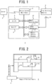
- Figs. 1 to 11 indicate a design system 2 (a generation system for correction data for inverse plating) and a method for generating the correction data, according to the embodiment.
- the design system 2 is connected to one or more flat knitting machines 4, and the program of the learned support vector regression analyzer (SVR) 8 and the data for regression analysis are provided from a server 5 and they are implemented in the design system 2.
- the SVR 8 uses the switching conditions between front and back yarns extracted from the knitting data as the explanatory variables, and outputs the positions where the switching operation should start (correction data) as the objective variable.
- the correction data for inverse plating can be automatically generated.
- an unlearned SVR can be implemented in the design system 2, and the SVR can learn in the design system 2 to generate the data for regression analysis in the design system 2.
- the regression analyzer can be a neural net, kNN (a k-nearest neighbor method analyzer), etc., instead of the SVR 8.
- the correction data for inverse plating, the objective variable in regression analysis has strong non-linearity with respect to the explanatory variables. Therefore, SVR, a neural net, kNN, and so on, are preferable among multiple regression analyzers, and SVR is particularly preferable.
- the memory 10 stores the driving data of the flat knitting machine 4 (knitting data) , and the knitting data includes the positions where the front yarn and the back yarn are switched in inverse plating. It further includes the identification numbers of the pair of carriers supplying the front yarn and the back yarn, their leading and following relationship, their front and back relationship, the knitting speed, the knitting direction, the needle bed used, etc.
- the data include all the relevant data to the switching conditions of the front yarn and the back yarn.
- An image recognition device 11 recognizes the actual position where the front yarn and the back yarn are switched during trial knitting from the images of the camera 14 installed in the flat knitting machine 4.
- a general-purpose memory 12 stores the correction data, etc., for switching the front and back yarns.
- the type of flat knitting machine 4 is optional, and the design system 2 can be installed in the flat knitting machine 4 as shown in Fig. 1 , or in the server 5.
- the relationship between the flat knitting machine 4, the design system 2, and the camera 14 is shown in Fig. 2 .
- the flat knitting machine 4 has, for example, a pair of front and back needle beds 15, 15, and a carriage 16 that operates the needles in the needle beds 15.
- Autonomously running carriers 25, 26, or the like supply the knitting yarns to the needles for inverse plating.
- the camera 14 is installed on the carriage 16 or autonomously running carriers 25, 26, etc.
- the carriers may not be an autonomously running type but may be a type of carriers driven by the carriage 16. In general, the carriers feed the knitting yarns from the yarn feeders at the bottom of the carriers.
- one carrier may be enough for inverse plating.
- the image recognition device 11 in the design system 2 recognizes the positions where the front and back yarns are switched and outputs the deviations from the desired positions of the switching. Then, for example, the correction data is finely adjusted by the amount of the deviations.
- the correction data can be finely adjusted by processing the deviations with an AI (a machine learning device) such as SVR 8. In either case, test-knitting is performed again, if necessary. In this way, the correction data can be generated almost automatically and finely adjusted by trial knitting without human intervention, and appropriate correction data are resultant.
- the correction data can also be finely adjusted by an operator who manually looks at the image from the camera 14 or visually inspects the knitted fabric, without using the design system 2.
- Fig. 3 indicates the learning of the SVR 8 (generation of the prediction model), the transfer of the prediction model to the design system 2 (Step S1 to Step S3), and the generation of correction data (Step S4 to S9).
- the correction data for inverse plating i.e., the data for each knitting condition, specifying the switching operation between front and back yarns, are affected by the following explanatory variables according to the experiences of the inventors.
- the SVR in the server 5 generates a prediction model that outputs the appropriate correction data as the objective variable for the input combination of explanatory variables, by machine learning (Step S2).
- a learned SVR 8 is generated within the server 5, and the generated learned SVR (the SVR's program and data for regression analysis) is implemented in the design systems 2 which are placed in knitting factories, etc., via communication lines, etc., (Step S3).
- the correction data is strongly non-linear to the explanatory variables. Therefore, SVR, neural net, kNN, and so on, which are suitable for non-linear phenomena, are preferable for the regression analyzer.
- explanatory variables regarding the switching between knitting yarns for inverse plating are extracted from the knitting data (Step S4).
- the extracted explanatory variables are inputted in the SVR 8, and the objective variable (the prediction data of the correction data) is generated (Step S5). Since the knitting yarns are switched plural times during knitting one piece of knitted fabric in inverse plating, the correction data is outputted for each combination of knitting conditions when switching.
- the design system 2 inputs the correction data according to the prediction values to the flat knitting machine 4, and test-knitting (trial knitting) is performed (Step S6).
- the correction data is finely adjusted to modify the correction data by this deviation (Step S8). Therefore, the trial knitting is performed once more, and, if satisfactory correction data is generated, trial knitting is completed and the correction data is outputted (Step S9).
- the fine adjustment of the correction data may be done manually or automatically.
- the fine adjustment of the correction data it is preferable to vary, for example, the correction data in multiple steps so that the user can determine how the correction data is most preferably adjusted. It is also possible to manually observe the knitted fabric without using the camera 14. Trial knitting after the fine adjustment may be omitted.
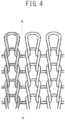
- Fig. 4 schematically shows the switching between the front and back yarns in inverse plating.
- the A-A line in the figure indicates the desired positions for the switching, and the error is how long the actual switching position deviates from the A-A line and also the direction of deviation of the left and the right.
- the correction data may be finely adjusted by the amount of this error.
- the error is processed by AI (machine learning device).
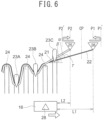
- FIG. 5 Examples of how the front and back yarns are switched in inverse plating are shown in Figs. 5 to 8 .
- the cam 28 of the carriage 16 operates the needles 23A to C, etc., and switches the front and back yarns from the knitting stitch formed by the needle 23C, for example.
- Sinkers 24 are placed between the needles 23, the carriage 16 runs towards the right in this embodiment.
- Indicated by 25, 26 are autonomously running carriers that supply the knitting yarns 21, 22 to the needles 23A-C, etc.
- the knitting yarn 21 is the front yarn up to needle 23B and becomes the back yarn from needle 23C.
- the carrier that supplies the front yarn is leading, and the carrier that supplies the back yarn is following.
- the one with the smaller yarn supply angle from the horizontal plane becomes the front yarn, and the one with the larger angle becomes the back yarn.
- the yarn supply angles are indicated by Alpha and Beta.
- P1 and P2 indicate the relative positions of the autonomously running carriers 25 and 26 with respect to the carriage 16
- L1 and L2 indicate the distances between the carriage 16 and the autonomously running carriers 25 and 26.
- the carriers 25, 26 are switched in the leading and following relation, and the switching position is determined with reference to the position of needle 23C where the switching takes place.
- the carriers 25 and 26 intersect at an intersection position CP which is determined with reference to the position of needle 23C. Therefore, the leading autonomously running carrier 25 is decelerated and the following autonomously running carrier 26 is accelerated such that the carriers 25 and 26 intersect at the intersection position CP.
- the carriers 25 and 26 are accelerated and decelerated such that they move at the same speed.
- the start position of deceleration and the start position of acceleration, for switching the relative position of the autonomously running carriers 25 and 26, are the correction data.
- Fig. 6 the switching shown in Fig. 5 is improved such that the carriers 25 and 26 are reversed as shown by the white arrows in the figure, in the coordinate system based on the position of carriage 16.
- P1' and P2' in Fig. 6 indicate the reversing positions of the movements of carriers 26 and 25.
- the knitting yarns 21 and 22 sometimes become entangled.
- the knitting yarns 21 and 22 become entangled only in the rear of the carriage's travelling direction.
- the switching between the front yarn and the back yarn is controlled more accurately, and the knitted fabric seems distinct without conspicuous blur because the switching positions are controlled accurately.
- the distance along which the reversing motion is performed may be added to the correction data.
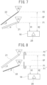
- Inverse plating can be carried out by switching the heights P1 and P2 of the pair of carriers 31, 32. Two embodiments are shown in Figs. 7 and 8 .
- the angles Alpha and Beta formed between the direction of the yarn feeding to the needles and the horizontal plane determine the assignment of the front and back yarns, and the yarn with the smaller angle becomes the front yarn. Therefore, a pair of carriers 31, 32 are made taken by the carriage 16 or made to run autonomously by themselves.
- the yarns are fed from the yarn feeders at the bottoms of the carriers 31, 32, and the carriers 31 and 32 are provided with elevating and lowering mechanisms for the yarn feeders, then inverse plating is capable of being performed.
- the knitting yarn 21 from the carrier 31 is at first the front yarn
- the knitting yarn 22 from carrier 32 is at first the back yarn.
- the yarn feeders of carriers 31, 32 are crossed in the height direction at the crossing position CP.
- H1 is the height for feeding the front yarn with the carriage being the reference height
- H2 is the height for feeding the back yarn with the carriage being the reference height.
- Fig. 8 the switching in Fig. 7 is improved, and the yarn feeder of the carrier 31 is raised to a position P2", then the movement is reversed and the yarn feeder is lowered. Also, the yarn feeder of carrier 32 is lowered to a position P1", then the movement is reversed, and the yarn feeder is raised.
- knitted fabrics with less blur compared to those according to Fig. 7 are knitted by inverse plating.
- the method of inverse plating is arbitrary as long as the correction data according to knitting conditions is required for the switching between the front and back yarns.
- the yarn feeding angles to the needle can be switched by rotating the carrier around the vertical axis. It is also possible to switch the tensions to the knitting yarns.
- the correction data indicates, for example, the switching timing of the tensions.
- the front yarn and the back yarn can be switched using movable sinkers.
- the methods in Figs. 5 to 8 can switch the yarns with less blur, and in Figs. 6 and 8 which involve the reversed operations, the yarns are switched with further less blur.
- Figs. 9 and 10 indicate the examples of learning data and prediction data of the objective variable (correction data) from SVR 8.
- SVR 8 learned for three speeds among the ten knitting speeds, and learned only for a portion of the carriers at the knitting speeds of 0.8 m/s and 1.0 m/s.
- the objective variable (correction data) indicates the position to start the switching of the carriers in the forward direction from the needle where the yarns are to be switched, in terms of needle pitch.
- the decimal point in the objective variable indicates the switching is controlled more accurately than the pitch of one needle.
- the acceleration/deceleration pattern themselves may be added to the objective variable in addition to the starting position of acceleration/deceleration for switching.
- the eighth carrier is moved from the leading to the following at the knitting speed of 0.8 m/s.
- the prediction value of SVR 8 is to start the switching operation of the eighth carrier at a position being 17.3 needles ahead of the desired needle.
- the prediction value of SVR 8 is for the counterpart seventh carrier is to start the switching operation at a position being 15.9 needles ahead of the desired needle, in order to move the seventh carrier from a following position to a leading position.
- the starting positions of the switching operation differ between the paired carriers.
- the correction data for the subsequent switching is indicated in Fig. 10 .
- the prediction value of the correction data for the seventh carrier is ahead by 15.7 needles, and for the eighth carrier, it is ahead by 16.3 needles.
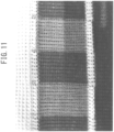
- Fig. 11 shows a knitted fabric knitted by inverse plating using the correction data in Figs. 9 and 10 .
- the fabric was knitted by circular knitting, and "1" in the figure indicates the position where the correction data of Fig. 9 was applied, and "2" in the figure indicates the position where the correction data of Fig. 10 was applied.
- the desired position for the switching is not the positions of the sinker loops, but the positions of the needle loops.
- the correction data as predicted by SVR 8 was used in the knitting without the fine adjustment, but when the correction data is finely adjusted, the switching positions of the front and back yarns can be controlled more accurately. In the embodiment, a distinct knitted fabric with less blur was obtained.
- inverse plating can be used to replace jacquard knitting and intarsia knitting.
- differences between individual flat knitting machines 4 are problematic, it is preferable to adjust finely the correction data for each flat knitting machine.
- they may further include yarn properties such as the width and the friction coefficient of knitting yarns, and the detailed yarn feeding direction of knitting yarns to the carriers, such as from the left, right, or top center of the needle beds.
Landscapes
- Engineering & Computer Science (AREA)
- Textile Engineering (AREA)
- Knitting Machines (AREA)
- Knitting Of Fabric (AREA)
Abstract
Description
- This invention relates to the generation of correction data for inverse plating. Plating is a knitting method where two knitting yarns are fed to knitting needles from one or two carriers in a flat knitting machine and one of them is knitted as the front yarn and the other is knitted as the back yarn. The inverse plating is one type of plating in which the assignment of the front and back yarns is switched. By the way, the kicking back of the carriers performed in intarsia knitting is not included in inverse plating. Correction data for inverse plating is, for example, the data that specifies the timing to start switching of the assignment of front and back yarns.
- Inverse plating is a new alternative to jacquard knitting and intarsia knitting, etc. Patent Document 1 (
EP3315,642B andJP6562,890B JP2018-178,292A - However, accurate switching between the front and back yarns at the desired positions is difficult to be performed. When the switching positions between the front and back yarns fluctuate, the blur of colors between the front yarn and the back yarn appear in the knitted fabric, for example. The current problem in inverse plating is to accurately switch the front and back yarns at the desired positions, and, in particular, to reduce the variation in the switching positions.
- For inverse plating, the exact timing to start switching the assignment of the front and back yarns should be specified. However, the correction data for this purpose can not be easily determined because it is affected by various factors. They are, for example, the combination of carriers used, the relative position in the direction of the front to the back of the flat knitting machine from a viewpoint in front of the flat knitting machine, in addition, the relative position in the direction of the knitting, the knitting speed, the knitting direction, and the needle bed used. For determining the correction data, it is necessary to perform test-knitting (trial knitting) many times on the flat knitting machine. Therefore, it is unrealistic to determine manually the appropriate correction data.
- Another related piece of prior art will be described. In the embodiments of the invention, autonomously running carriers are used. Autonomously running carriers have been known and it is also known that they can be used for plating (Patent Document 3:
EP2246,466B andWO2009/081,583 ). However,Patent Document 3 does not refer to inverse plating. -
- Patent Document 1:
EP3315,642B (JP6562,890B - Patent Document 2:
JP2018-178,292A - Patent Document 3:
EP2246,466B (WO2009/081,583 ) - The problem of this invention is to generate easily the correction data for inverse plating accompanying less blurring. This makes inverse plating more practical.
- The inventive method for generating correction data for inverse plating that uses a flat knitting machine, feeds two knitting yarns from at least one carrier, one as a front yarn and the other as a back yarn, moves a carriage in one direction, knits a knitted fabric by plating, and switches the assignment of the front yarn and the back yarn without interrupting the knitting,
is characterized by using a learned regression analysis device that has explanatory variables comprising knitting conditions at the time of the switching and an objective variable comprising correction data for the switching, and generating the correction data for the switching by the learned regression analysis device. - The inventive system for generating correction data for inverse plating where a flat knitting machine is used, two knitting yarns are fed from at least one carrier, one as a front yarn and the other as a back yarn, a carriage is moved in one direction, a knitted fabric is knitted by plating, and the assignment of the front yarn and the back yarn is switched,
is characterized by a learned regression analysis device having explanatory variables comprising knitting conditions at the time of the switching and an objective variable comprising correction data for the switching, and configured to generate the correction data for the switching from the input of the knitting conditions at the time of the switching. - According to the invention, a learned regression analysis device generates the correction data from the knitting conditions at the time of switching between front and back yarns in inverse plating. Since the correction data is generated by the learned regression analysis device, there is no need to manually obtain the correction data for all the knitting conditions. In addition, regression analysis enables to generate the correction data usable in practice with fine adjustments through trial knitting.
- Preferably, a knitted fabric is test-knitted on a flat knitting machine, according to the correction data for the switching generated from the learned regression analysis device, and the correction data for the switching is finely adjusted based on the test-knitted fabric. Since there are factors not taken into account in the regression analysis, such as the type of yarn used in the knitting and the lot number of the yarn, there is no guarantee that the correction data will enable appropriate inverse plating from the beginning. Therefore, the test-knitting of the knitted fabric and the fine adjustment of the correction enable inverse plating with less blur.
- More preferably, an image of the test-knitted fabric is taken by a camera, the switching portion between the knitting yarns in the image is image-recognized by an image recognition means, and the correction data for the switching is finely adjusted automatically or manually. In this way, the fine adjustment of the correction data is easily performed. In particular, using the image recognition means allows the fine adjustment of the correction data almost automatically.
- Preferably, a pair of autonomously running carriers are moved in synchronization with the carriage,
- the assignment of the front yarn and the back yarn is switched by switching the back-and-forth relationship between the two autonomously running carriers in the direction of the running of carriage, and
- the knitting conditions at the time of the switching comprises:
- the carrier to be corrected;
- the knitting speed;
- the needle bed;
- the knitting direction;
- the distinction whether the carrier to be corrected will be switched from the leading position to the following position or from the following position to the leading position; and
- the distinction whether the carrier to be corrected is relatively positioned at a front-ward position or a rear-ward position in the flat knitting machine, compared to the other carrier of the pair of carriers, from a viewpoint in front of the flat knitting machine.
- When two autonomously running carriers run in synchronization with the carriage and the assignment of the front and back yarns is switched by switching the leading and following relationship between the autonomously running carriers in the carriage running direction, the blur according to inadequate switching between the front and back yarns is reduced. In this case, the above six types of knitting conditions are related to the correction data, and there are very many combinations of them. Appropriate correction data can be generated for the large number of combinations by using a regression analysis device.
- Preferably, the learned regression analysis device is a support vector regression analyzer. Since the correction data for inverse plating does not depend linearly on the explanatory variables, a regression analyzer suitable for the analysis of nonlinear phenomena is preferable. Among regression analyzers, a support vector regression analyzer is preferable. The present inventors have succeeded in generating appropriate correction data using a support vector regression analyzer.
-
-
Fig. 1 is a block diagram of a design system according to an embodiment, with a peripheral server and a peripheral flat knitting machine. -
Fig. 2 is a schematic diagram indicating a fine adjustment mechanism of the correction data. -
Fig. 3 is a flowchart of an algorithm for generating correction data for inverse plating. -
Fig. 4 is a schematic drawing indicating the switching positions between the front and back yarns (the A-A line) in inverse plating by switching the front-back relationship between the carriers. -
Fig. 5 is a schematic drawing indicating the switching between the front and back yarns by switching their leading and following relationship of the carriers, in inverse plating. -
Fig. 6 is a schematic drawing of the switching shown inFig. 5 with the inversions of the motional directions of the carriers. -
Fig. 7 is a schematic drawing of the switching between the front and back yarns by switching the relative height of the yarn feeders in the carriers. -
Fig. 8 is a drawing indicating an example comprising the switching inFig. 7 and the reverse motion of yarn feeders in the height direction. -
Fig. 9 is a diagram indicating an example of the learning data and the prediction data of the correction data outputted by a support vector regression analyzer (SVR). The objective variable is the position to start the switching of the leading and following relationship between yarn feeders (correction data), and the switching mechanism is one indicated inFig. 5 . -
Fig. 10 is a diagram indicating another example of the learning data, and the prediction data of the correction data outputted by the support vector regression analyzer (SVR). -
Fig. 11 is a photograph of the knitted fabric that was knitted by the inverse plating according to the correction data generated inFigs. 9 and10 . - The best embodiment will be described.
-
Figs. 1 to 11 indicate a design system 2 (a generation system for correction data for inverse plating) and a method for generating the correction data, according to the embodiment. InFig. 1 , thedesign system 2 is connected to one or moreflat knitting machines 4, and the program of the learned support vector regression analyzer (SVR) 8 and the data for regression analysis are provided from aserver 5 and they are implemented in thedesign system 2. TheSVR 8 uses the switching conditions between front and back yarns extracted from the knitting data as the explanatory variables, and outputs the positions where the switching operation should start (correction data) as the objective variable. By implementing the learnedSVR 8 in thedesign system 2, the correction data for inverse plating can be automatically generated. By the way, an unlearned SVR can be implemented in thedesign system 2, and the SVR can learn in thedesign system 2 to generate the data for regression analysis in thedesign system 2. - The regression analyzer can be a neural net, kNN (a k-nearest neighbor method analyzer), etc., instead of the
SVR 8. The correction data for inverse plating, the objective variable in regression analysis, has strong non-linearity with respect to the explanatory variables. Therefore, SVR, a neural net, kNN, and so on, are preferable among multiple regression analyzers, and SVR is particularly preferable. - Indicated by 9 is a user interface, such as a display, a mouse, a keyboard, a pen, and so on. The
memory 10 stores the driving data of the flat knitting machine 4 (knitting data) , and the knitting data includes the positions where the front yarn and the back yarn are switched in inverse plating. It further includes the identification numbers of the pair of carriers supplying the front yarn and the back yarn, their leading and following relationship, their front and back relationship, the knitting speed, the knitting direction, the needle bed used, etc. The data include all the relevant data to the switching conditions of the front yarn and the back yarn. - An
image recognition device 11 recognizes the actual position where the front yarn and the back yarn are switched during trial knitting from the images of thecamera 14 installed in theflat knitting machine 4. A general-purpose memory 12 stores the correction data, etc., for switching the front and back yarns. The type offlat knitting machine 4 is optional, and thedesign system 2 can be installed in theflat knitting machine 4 as shown inFig. 1 , or in theserver 5. - The relationship between the
flat knitting machine 4, thedesign system 2, and thecamera 14 is shown inFig. 2 . Theflat knitting machine 4 has, for example, a pair of front andback needle beds carriage 16 that operates the needles in theneedle beds 15. Autonomously runningcarriers camera 14 is installed on thecarriage 16 or autonomously runningcarriers carriage 16. In general, the carriers feed the knitting yarns from the yarn feeders at the bottom of the carriers. In addition, when multiple yarn feeders are installed in one carrier and a mechanism is installed to switch the relative heights of the yarn feeders, one carrier may be enough for inverse plating. - In inverse plating, the assignment of the front and back yarns is switched, but it is difficult to switch them accurately at the desired positions. Therefore, the knitted fabric or the stitches on the trick gap between the needle beds are imaged, the captured image is inputted to the
design system 2, and the correction data is finely adjusted. Indicated by 18 is the controller of theflat knitting machine 4 and it controls thecarriage 16, the autonomously runningcarriers - Returning to
Fig. 1 , theimage recognition device 11 in thedesign system 2 recognizes the positions where the front and back yarns are switched and outputs the deviations from the desired positions of the switching. Then, for example, the correction data is finely adjusted by the amount of the deviations. Alternatively, the correction data can be finely adjusted by processing the deviations with an AI (a machine learning device) such asSVR 8. In either case, test-knitting is performed again, if necessary. In this way, the correction data can be generated almost automatically and finely adjusted by trial knitting without human intervention, and appropriate correction data are resultant. In addition, the correction data can also be finely adjusted by an operator who manually looks at the image from thecamera 14 or visually inspects the knitted fabric, without using thedesign system 2. -
Fig. 3 indicates the learning of the SVR 8 (generation of the prediction model), the transfer of the prediction model to the design system 2 (Step S1 to Step S3), and the generation of correction data (Step S4 to S9). The correction data for inverse plating, i.e., the data for each knitting condition, specifying the switching operation between front and back yarns, are affected by the following explanatory variables according to the experiences of the inventors. - Carrier number: An identification number assigned to
carriers flat knitting machine 4, indicating the position of the carriers in the front to back direction of theflat knitting machine 4. In the embodiments, the number is 1 to 8. - Front/back: A binary data indicating whether the relative position of the carrier to be corrected is either front or back between the pair of carriers for switching the front and back yarns, in the front to back direction of the
flat knitting machine 4. - Leading/following: A binary data indicating whether the carrier to be corrected is either leading or following between the relevant pair of carriers.
- Needle bed: A binary data indicating whether the front or back needle bed is used for the instantaneous knitting. Regarding flat knitting machines having four needle beds of front and back and up and down, the data indicates fours positions of the front and back and the up and down, and the data has a value same to the number of needle beds in the flat knitting machine.
- Knitting direction: A binary data indicating the knitting direction when the front and back yarns are switched. It comprises "towards the right" and "towards the left" from a viewpoint in front of the
flat knitting machine 4. - Knitting speed: The knitting speed (the movement speed of the carriage) when the front and back yarns are switched. In the embodiments, the data comprises, for example, 10 levels.
- In the embodiment, there are a total of 1,280 combinations of these explanatory variables. It is unrealistic to obtain the optimum correction data for 1280 combinations by actually operating the
flat knitting machine 4 for all the combinations. Therefore, for example, about 100 combinations, or in other words, about 10% of all the combinations of explanatory variables, theflat knitting machine 4 is operated to generate the appropriate correction data at the combinations. The generated appropriate correction data and combinations of explanatory variables are inputted to the SVR in the server 5 (Step S1) . - The SVR in the
server 5 generates a prediction model that outputs the appropriate correction data as the objective variable for the input combination of explanatory variables, by machine learning (Step S2). In other words, a learnedSVR 8 is generated within theserver 5, and the generated learned SVR (the SVR's program and data for regression analysis) is implemented in thedesign systems 2 which are placed in knitting factories, etc., via communication lines, etc., (Step S3). Regarding the switching between knitting yarns in inverse plating, the correction data is strongly non-linear to the explanatory variables. Therefore, SVR, neural net, kNN, and so on, which are suitable for non-linear phenomena, are preferable for the regression analyzer. - In the
design system 2, explanatory variables regarding the switching between knitting yarns for inverse plating are extracted from the knitting data (Step S4). The extracted explanatory variables are inputted in theSVR 8, and the objective variable (the prediction data of the correction data) is generated (Step S5). Since the knitting yarns are switched plural times during knitting one piece of knitted fabric in inverse plating, the correction data is outputted for each combination of knitting conditions when switching. - The
design system 2 inputs the correction data according to the prediction values to theflat knitting machine 4, and test-knitting (trial knitting) is performed (Step S6). Acamera 14, for example, mounted on an autonomously running carrier or thecarriage 16, images the knitted stitches, and theimage recognition device 11 confirms the position where the front yarn and the back yarn are switched in the image from the camera (Step S7). When the switching position deviates from the desired position, the correction data is finely adjusted to modify the correction data by this deviation (Step S8). Therefore, the trial knitting is performed once more, and, if satisfactory correction data is generated, trial knitting is completed and the correction data is outputted (Step S9). The fine adjustment of the correction data may be done manually or automatically. In the fine adjustment of the correction data, it is preferable to vary, for example, the correction data in multiple steps so that the user can determine how the correction data is most preferably adjusted. It is also possible to manually observe the knitted fabric without using thecamera 14. Trial knitting after the fine adjustment may be omitted. -
Fig. 4 schematically shows the switching between the front and back yarns in inverse plating. The A-A line in the figure indicates the desired positions for the switching, and the error is how long the actual switching position deviates from the A-A line and also the direction of deviation of the left and the right. In simple processing, the correction data may be finely adjusted by the amount of this error. For more complex processing, the error is processed by AI (machine learning device). - Examples of how the front and back yarns are switched in inverse plating are shown in
Figs. 5 to 8 . InFig. 5 , thecam 28 of thecarriage 16 operates theneedles 23A to C, etc., and switches the front and back yarns from the knitting stitch formed by theneedle 23C, for example.Sinkers 24 are placed between the needles 23, thecarriage 16 runs towards the right in this embodiment. Indicated by 25, 26 are autonomously running carriers that supply theknitting yarns needles 23A-C, etc. Theknitting yarn 21 is the front yarn up toneedle 23B and becomes the back yarn fromneedle 23C. In addition, the carrier that supplies the front yarn is leading, and the carrier that supplies the back yarn is following. Between theknitting yarns carriers carriage 16, and L1 and L2 indicate the distances between thecarriage 16 and the autonomously runningcarriers - In the switching between the front and back yarns, the
carriers needle 23C where the switching takes place. For example, thecarriers needle 23C. Therefore, the leading autonomously runningcarrier 25 is decelerated and the following autonomously runningcarrier 26 is accelerated such that thecarriers carriage 16 are swapped, thecarriers carriers - In
Fig. 6 , the switching shown inFig. 5 is improved such that thecarriers carriage 16. P1' and P2' inFig. 6 indicate the reversing positions of the movements ofcarriers carriers knitting yarns needle 23C in the carriage's traveling direction, the knitting yarns will not be switched correctly. However, when the reversing operation is performed, theknitting yarns - Inverse plating can be carried out by switching the heights P1 and P2 of the pair of
carriers Figs. 7 and 8 . The angles Alpha and Beta formed between the direction of the yarn feeding to the needles and the horizontal plane determine the assignment of the front and back yarns, and the yarn with the smaller angle becomes the front yarn. Therefore, a pair ofcarriers carriage 16 or made to run autonomously by themselves. The yarns are fed from the yarn feeders at the bottoms of thecarriers carriers - In
Fig. 7 , theknitting yarn 21 from thecarrier 31 is at first the front yarn, and theknitting yarn 22 fromcarrier 32 is at first the back yarn. The yarn feeders ofcarriers - In
Fig. 8 , the switching inFig. 7 is improved, and the yarn feeder of thecarrier 31 is raised to a position P2", then the movement is reversed and the yarn feeder is lowered. Also, the yarn feeder ofcarrier 32 is lowered to a position P1", then the movement is reversed, and the yarn feeder is raised. In the switching according toFig. 8 , knitted fabrics with less blur compared to those according toFig. 7 are knitted by inverse plating. - The method of inverse plating is arbitrary as long as the correction data according to knitting conditions is required for the switching between the front and back yarns. For example, the yarn feeding angles to the needle can be switched by rotating the carrier around the vertical axis. It is also possible to switch the tensions to the knitting yarns. In this case, the correction data indicates, for example, the switching timing of the tensions. In addition, the front yarn and the back yarn can be switched using movable sinkers. However, compared to these switching methods, the methods in
Figs. 5 to 8 can switch the yarns with less blur, and inFigs. 6 and8 which involve the reversed operations, the yarns are switched with further less blur. -
Figs. 9 and10 indicate the examples of learning data and prediction data of the objective variable (correction data) fromSVR 8.SVR 8 learned for three speeds among the ten knitting speeds, and learned only for a portion of the carriers at the knitting speeds of 0.8 m/s and 1.0 m/s. The objective variable (correction data) indicates the position to start the switching of the carriers in the forward direction from the needle where the yarns are to be switched, in terms of needle pitch. The decimal point in the objective variable indicates the switching is controlled more accurately than the pitch of one needle. When controlling the acceleration/deceleration pattern of the carriers during the switching operation, the acceleration/deceleration pattern themselves may be added to the objective variable in addition to the starting position of acceleration/deceleration for switching. - For example, in the case of the left side of
Fig. 9 , the eighth carrier is moved from the leading to the following at the knitting speed of 0.8 m/s. In this case, the prediction value ofSVR 8 is to start the switching operation of the eighth carrier at a position being 17.3 needles ahead of the desired needle. The prediction value ofSVR 8 is for the counterpart seventh carrier is to start the switching operation at a position being 15.9 needles ahead of the desired needle, in order to move the seventh carrier from a following position to a leading position. The starting positions of the switching operation differ between the paired carriers. - Switching between the seventh and eighth carriers often requires subsequent switchings in the opposite direction between the same pair of carriers. The correction data for the subsequent switching is indicated in
Fig. 10 . In this case, the prediction value of the correction data for the seventh carrier is ahead by 15.7 needles, and for the eighth carrier, it is ahead by 16.3 needles. -
Fig. 11 shows a knitted fabric knitted by inverse plating using the correction data inFigs. 9 and10 . The fabric was knitted by circular knitting, and "1" in the figure indicates the position where the correction data ofFig. 9 was applied, and "2" in the figure indicates the position where the correction data ofFig. 10 was applied. The desired position for the switching is not the positions of the sinker loops, but the positions of the needle loops. In this embodiment, the correction data as predicted bySVR 8 was used in the knitting without the fine adjustment, but when the correction data is finely adjusted, the switching positions of the front and back yarns can be controlled more accurately. In the embodiment, a distinct knitted fabric with less blur was obtained. Thus, with relatively little preparation work, inverse plating can be used to replace jacquard knitting and intarsia knitting. When differences between individualflat knitting machines 4 are problematic, it is preferable to adjust finely the correction data for each flat knitting machine. With respect to the explanatory variables, they may further include yarn properties such as the width and the friction coefficient of knitting yarns, and the detailed yarn feeding direction of knitting yarns to the carriers, such as from the left, right, or top center of the needle beds. -
- 2
- design system
- 4
- flat knitting machine
- 5
- server
- 6
- design system main unit
- 8
- support vector regression analyzer (SVR)
- 9
- user interface
- 10
- memory (knitting data)
- 11
- image recognition device
- 12
- memory (general-purpose)
- 14
- camera
- 15
- needle bed
- 16
- carriage
- 18
- controller
- 19
- knitted fabric
- 21, 22
- knitting yarns
- 23A to 23C
- Needles
- 24
- sinker
- 25, 26
- autonomously running carriers
- 28
- cam
- 31, 32
- up and down carriers
- CP
- intersection position
- L1, L2
- distance from carriage
- P1
- front yarn supply position
- P2
- back yarn supply position
- H1, H2
- height of carriage reference
- Alpha, Beta
- yarn feeding angle from a horizontal plane
Claims (6)
- A method for generating correction data for inverse plating, using a flat knitting machine, feeding two knitting yarns from at least one carrier, one as a front yarn and the other as a back yarn, moving a carriage in one direction, knitting a knitted fabric by plating, and switching the assignment of the front yarn and the back yarn without interrupting the knitting,
being characterized by using a learned regression analysis device having explanatory variables comprising knitting conditions at the time of the switching and an objective variable comprising correction data for the switching and generating the correction data for the switching. - The method for generating the correction data for inverse plating according to claim 1,
being characterized by performing test-knitting of a knitted fabric on a flat knitting machine, according to the correction data for the switching generated from the learned regression analysis device, and finely adjusting the correction data for the switching based on the test-knitted fabric. - The method for generating correction data for inverse plating according to claim 2,
being characterized by taking an image of the test-knitted fabric by a camera, image-recognizing the switching portion between the knitting yarns in the image by an image recognition means, and finely adjusting the correction data for the switching automatically or manually. - The method for generating correction data for inverse plating according to one of claims 1 to 3,being characterized by running a pair of autonomously running carriers in synchronization with the carriage,switching the assignment of the front yarn and the back yarn by switching the back-and-forth relationship between the two autonomously running carriers in the direction of the running of carriage, and being characterized in thatthe knitting conditions at the time of the switching comprise:the carrier to be corrected;the knitting speed;the needle bed;the knitting direction;the distinction whether the carrier to be corrected will be switched from the leading position to the following position or from the following position to the leading position; andthe distinction whether the carrier to be corrected is relatively positioned at a front-ward position or a rear-ward position in the flat knitting machine, compared to the other carrier of the pair of carriers, from a viewpoint in front of the flat knitting machine.
- The method for generating correction data for inverse plating according to one of claims 1 to 4, being characterized in that the regression analysis device is a support vector regression analysis device.
- A system for generating correction data for inverse plating that uses a flat knitting machine, feeds two knitting yarns from at least one carrier, one as a front yarn and the other as a back yarn, moves a carriage in one direction, knits a knitted fabric by plating, and switches the assignment of the front yarn and the back yarn,
being characterized by a learned regression analysis device having explanatory variables comprising knitting conditions at the time of the switching and an objective variable comprising correction data for the switching, and configured to generate the correction data for the switching from the input of the knitting conditions at the time of the switching.
Applications Claiming Priority (2)
| Application Number | Priority Date | Filing Date | Title |
|---|---|---|---|
| JP2021008627 | 2021-01-22 | ||
| PCT/JP2021/048124 WO2022158251A1 (en) | 2021-01-22 | 2021-12-24 | Production method and production system for correction data for inverse plating |
Publications (2)
| Publication Number | Publication Date |
|---|---|
| EP4283031A1 true EP4283031A1 (en) | 2023-11-29 |
| EP4283031A4 EP4283031A4 (en) | 2024-07-10 |
Family
ID=82548444
Family Applications (1)
| Application Number | Title | Priority Date | Filing Date |
|---|---|---|---|
| EP21921352.7A Withdrawn EP4283031A4 (en) | 2021-01-22 | 2021-12-24 | PRODUCTION METHOD AND SYSTEM FOR PRODUCING CORRECTION DATA FOR REVERSE VANIZATION |
Country Status (5)
| Country | Link |
|---|---|
| EP (1) | EP4283031A4 (en) |
| JP (1) | JPWO2022158251A1 (en) |
| KR (1) | KR20230132830A (en) |
| CN (1) | CN116745477A (en) |
| WO (1) | WO2022158251A1 (en) |
Families Citing this family (1)
| Publication number | Priority date | Publication date | Assignee | Title |
|---|---|---|---|---|
| EP4474558A1 (en) | 2023-06-07 | 2024-12-11 | Canmartex Catgrup, S.L. | Method for adjusting an automatic knitting machine for plating knitting, and corresponding system |
Family Cites Families (8)
| Publication number | Priority date | Publication date | Assignee | Title |
|---|---|---|---|---|
| JPS6038718A (en) | 1983-08-10 | 1985-02-28 | Teijin Ltd | Vertical magnetic recording medium |
| JP2008234623A (en) * | 2007-02-19 | 2008-10-02 | Seiko Epson Corp | Category identification device, category identification method, and program |
| WO2009081583A1 (en) | 2007-12-25 | 2009-07-02 | Shima Seiki Mfg., Ltd. | Weft knitting machine, and control method for mobile carrier in the weft knitting machine |
| WO2016044288A1 (en) * | 2014-09-15 | 2016-03-24 | Appalatch Outdoor Apparel Company | Systems, methods, and software for manufacturing a custom-knitted article |
| EP3447178B1 (en) * | 2016-04-22 | 2022-10-19 | Shima Seiki Mfg., Ltd. | Grading method and grading system for knitted product |
| JP6562890B2 (en) | 2016-10-31 | 2019-08-21 | 株式会社島精機製作所 | Plating knitting method and flat knitting machine used therefor |
| JP2018178292A (en) | 2017-04-07 | 2018-11-15 | 株式会社島精機製作所 | Knitting fabric formation method |
| JP7285704B2 (en) * | 2019-06-18 | 2023-06-02 | 株式会社島精機製作所 | KNITTING MACHINE DRIVING DATA PROCESSING METHOD AND PROCESSING SYSTEM USING MACHINE LEARNING |
-
2021
- 2021-12-24 EP EP21921352.7A patent/EP4283031A4/en not_active Withdrawn
- 2021-12-24 CN CN202180091336.1A patent/CN116745477A/en not_active Withdrawn
- 2021-12-24 WO PCT/JP2021/048124 patent/WO2022158251A1/en not_active Ceased
- 2021-12-24 JP JP2022577064A patent/JPWO2022158251A1/ja not_active Withdrawn
- 2021-12-24 KR KR1020237028066A patent/KR20230132830A/en active Pending
Also Published As
| Publication number | Publication date |
|---|---|
| KR20230132830A (en) | 2023-09-18 |
| EP4283031A4 (en) | 2024-07-10 |
| CN116745477A (en) | 2023-09-12 |
| WO2022158251A1 (en) | 2022-07-28 |
| JPWO2022158251A1 (en) | 2022-07-28 |
Similar Documents
| Publication | Publication Date | Title |
|---|---|---|
| JP6696035B1 (en) | Weft knitting machine structure in which the position of knitting yarn can be changed | |
| EP3315642B1 (en) | A plating-knitting method and a flat knitting machine for the method | |
| CN101796234B (en) | Flat knitting machine and its yarn feeding method | |
| CN114541021B (en) | Knitting method and knitting device | |
| US11136698B2 (en) | Weft knitting machine knitting structure with changeable yarn positions | |
| CN1054896C (en) | Method and apparatus for controlling of warp supply in warp knitting machine | |
| EP2280104B1 (en) | Device and program for loop length routine setting in a flatbed knitting machine | |
| KR101569011B1 (en) | Flat knitting machine and knitting method using flat knitting machine | |
| CN104831460A (en) | Automatic yarn adjusting and feeding apparatus of circular knitting machine | |
| WO2022158251A1 (en) | Production method and production system for correction data for inverse plating | |
| CN108978065A (en) | embroidery tufting machine and embroidery tufting method | |
| US4581905A (en) | Process and weaving machine to produce patterned fabrics | |
| JPH09217254A (en) | Formation of crossing yarn-fixing part | |
| CN112095210A (en) | Method and system for processing driving data of knitting machine by machine learning | |
| CN100503927C (en) | Weft knitting machine, knitting method, and knitting program generation device | |
| EP3702501A1 (en) | Method for knitting three-dimensional fabric with variable thickness through a flat knitting machine | |
| US4389860A (en) | Warp knitting machine for the production of jacquard-patterned pile-knit fabrics | |
| JP2017176463A (en) | Sewing data generation program and sewing data generation device | |
| US11781253B1 (en) | Circular knitting machine structure | |
| KR102697548B1 (en) | Circular knitting machine structure | |
| KR102232288B1 (en) | Weft knitting machine knitting structure with changeable yarn positions | |
| JP6557432B1 (en) | Method for knitting a three-dimensional knitted fabric having different thicknesses using a flat knitting machine | |
| US3606771A (en) | Yarn feeder control mechanism for circular knitting machines | |
| JPH0949154A (en) | Patterning by flat knitting machine and carrier device for flat knitting machine for patterning | |
| KR102811852B1 (en) | Cylinder and dial knitting machine |
Legal Events
| Date | Code | Title | Description |
|---|---|---|---|
| STAA | Information on the status of an ep patent application or granted ep patent |
Free format text: STATUS: THE INTERNATIONAL PUBLICATION HAS BEEN MADE |
|
| PUAI | Public reference made under article 153(3) epc to a published international application that has entered the european phase |
Free format text: ORIGINAL CODE: 0009012 |
|
| STAA | Information on the status of an ep patent application or granted ep patent |
Free format text: STATUS: REQUEST FOR EXAMINATION WAS MADE |
|
| 17P | Request for examination filed |
Effective date: 20230718 |
|
| AK | Designated contracting states |
Kind code of ref document: A1 Designated state(s): AL AT BE BG CH CY CZ DE DK EE ES FI FR GB GR HR HU IE IS IT LI LT LU LV MC MK MT NL NO PL PT RO RS SE SI SK SM TR |
|
| DAV | Request for validation of the european patent (deleted) | ||
| DAX | Request for extension of the european patent (deleted) | ||
| A4 | Supplementary search report drawn up and despatched |
Effective date: 20240611 |
|
| RIC1 | Information provided on ipc code assigned before grant |
Ipc: D04B 1/00 20060101ALI20240605BHEP Ipc: D04B 35/00 20060101AFI20240605BHEP |
|
| GRAP | Despatch of communication of intention to grant a patent |
Free format text: ORIGINAL CODE: EPIDOSNIGR1 |
|
| STAA | Information on the status of an ep patent application or granted ep patent |
Free format text: STATUS: GRANT OF PATENT IS INTENDED |
|
| INTG | Intention to grant announced |
Effective date: 20250403 |
|
| STAA | Information on the status of an ep patent application or granted ep patent |
Free format text: STATUS: THE APPLICATION IS DEEMED TO BE WITHDRAWN |
|
| 18D | Application deemed to be withdrawn |
Effective date: 20250805 |