EP4283010A1 - Method of forming protective coating and coated article comprising protective coating - Google Patents
Method of forming protective coating and coated article comprising protective coating Download PDFInfo
- Publication number
- EP4283010A1 EP4283010A1 EP23170250.7A EP23170250A EP4283010A1 EP 4283010 A1 EP4283010 A1 EP 4283010A1 EP 23170250 A EP23170250 A EP 23170250A EP 4283010 A1 EP4283010 A1 EP 4283010A1
- Authority
- EP
- European Patent Office
- Prior art keywords
- layer
- slots
- top coat
- substrate
- glazed
- Prior art date
- Legal status (The legal status is an assumption and is not a legal conclusion. Google has not performed a legal analysis and makes no representation as to the accuracy of the status listed.)
- Pending
Links
Images










Classifications
-
- C—CHEMISTRY; METALLURGY
- C23—COATING METALLIC MATERIAL; COATING MATERIAL WITH METALLIC MATERIAL; CHEMICAL SURFACE TREATMENT; DIFFUSION TREATMENT OF METALLIC MATERIAL; COATING BY VACUUM EVAPORATION, BY SPUTTERING, BY ION IMPLANTATION OR BY CHEMICAL VAPOUR DEPOSITION, IN GENERAL; INHIBITING CORROSION OF METALLIC MATERIAL OR INCRUSTATION IN GENERAL
- C23C—COATING METALLIC MATERIAL; COATING MATERIAL WITH METALLIC MATERIAL; SURFACE TREATMENT OF METALLIC MATERIAL BY DIFFUSION INTO THE SURFACE, BY CHEMICAL CONVERSION OR SUBSTITUTION; COATING BY VACUUM EVAPORATION, BY SPUTTERING, BY ION IMPLANTATION OR BY CHEMICAL VAPOUR DEPOSITION, IN GENERAL
- C23C28/00—Coating for obtaining at least two superposed coatings either by methods not provided for in a single one of groups C23C2/00 - C23C26/00 or by combinations of methods provided for in subclasses C23C and C25C or C25D
- C23C28/30—Coatings combining at least one metallic layer and at least one inorganic non-metallic layer
- C23C28/34—Coatings combining at least one metallic layer and at least one inorganic non-metallic layer including at least one inorganic non-metallic material layer, e.g. metal carbide, nitride, boride, silicide layer and their mixtures, enamels, phosphates and sulphates
- C23C28/345—Coatings combining at least one metallic layer and at least one inorganic non-metallic layer including at least one inorganic non-metallic material layer, e.g. metal carbide, nitride, boride, silicide layer and their mixtures, enamels, phosphates and sulphates with at least one oxide layer
- C23C28/3455—Coatings combining at least one metallic layer and at least one inorganic non-metallic layer including at least one inorganic non-metallic material layer, e.g. metal carbide, nitride, boride, silicide layer and their mixtures, enamels, phosphates and sulphates with at least one oxide layer with a refractory ceramic layer, e.g. refractory metal oxide, ZrO2, rare earth oxides or a thermal barrier system comprising at least one refractory oxide layer
-
- C—CHEMISTRY; METALLURGY
- C04—CEMENTS; CONCRETE; ARTIFICIAL STONE; CERAMICS; REFRACTORIES
- C04B—LIME, MAGNESIA; SLAG; CEMENTS; COMPOSITIONS THEREOF, e.g. MORTARS, CONCRETE OR LIKE BUILDING MATERIALS; ARTIFICIAL STONE; CERAMICS; REFRACTORIES; TREATMENT OF NATURAL STONE
- C04B41/00—After-treatment of mortars, concrete, artificial stone or ceramics; Treatment of natural stone
- C04B41/80—After-treatment of mortars, concrete, artificial stone or ceramics; Treatment of natural stone of only ceramics
- C04B41/81—Coating or impregnation
- C04B41/85—Coating or impregnation with inorganic materials
- C04B41/86—Glazes; Cold glazes
-
- C—CHEMISTRY; METALLURGY
- C04—CEMENTS; CONCRETE; ARTIFICIAL STONE; CERAMICS; REFRACTORIES
- C04B—LIME, MAGNESIA; SLAG; CEMENTS; COMPOSITIONS THEREOF, e.g. MORTARS, CONCRETE OR LIKE BUILDING MATERIALS; ARTIFICIAL STONE; CERAMICS; REFRACTORIES; TREATMENT OF NATURAL STONE
- C04B41/00—After-treatment of mortars, concrete, artificial stone or ceramics; Treatment of natural stone
- C04B41/0072—Heat treatment
-
- C—CHEMISTRY; METALLURGY
- C23—COATING METALLIC MATERIAL; COATING MATERIAL WITH METALLIC MATERIAL; CHEMICAL SURFACE TREATMENT; DIFFUSION TREATMENT OF METALLIC MATERIAL; COATING BY VACUUM EVAPORATION, BY SPUTTERING, BY ION IMPLANTATION OR BY CHEMICAL VAPOUR DEPOSITION, IN GENERAL; INHIBITING CORROSION OF METALLIC MATERIAL OR INCRUSTATION IN GENERAL
- C23C—COATING METALLIC MATERIAL; COATING MATERIAL WITH METALLIC MATERIAL; SURFACE TREATMENT OF METALLIC MATERIAL BY DIFFUSION INTO THE SURFACE, BY CHEMICAL CONVERSION OR SUBSTITUTION; COATING BY VACUUM EVAPORATION, BY SPUTTERING, BY ION IMPLANTATION OR BY CHEMICAL VAPOUR DEPOSITION, IN GENERAL
- C23C28/00—Coating for obtaining at least two superposed coatings either by methods not provided for in a single one of groups C23C2/00 - C23C26/00 or by combinations of methods provided for in subclasses C23C and C25C or C25D
-
- C—CHEMISTRY; METALLURGY
- C23—COATING METALLIC MATERIAL; COATING MATERIAL WITH METALLIC MATERIAL; CHEMICAL SURFACE TREATMENT; DIFFUSION TREATMENT OF METALLIC MATERIAL; COATING BY VACUUM EVAPORATION, BY SPUTTERING, BY ION IMPLANTATION OR BY CHEMICAL VAPOUR DEPOSITION, IN GENERAL; INHIBITING CORROSION OF METALLIC MATERIAL OR INCRUSTATION IN GENERAL
- C23C—COATING METALLIC MATERIAL; COATING MATERIAL WITH METALLIC MATERIAL; SURFACE TREATMENT OF METALLIC MATERIAL BY DIFFUSION INTO THE SURFACE, BY CHEMICAL CONVERSION OR SUBSTITUTION; COATING BY VACUUM EVAPORATION, BY SPUTTERING, BY ION IMPLANTATION OR BY CHEMICAL VAPOUR DEPOSITION, IN GENERAL
- C23C28/00—Coating for obtaining at least two superposed coatings either by methods not provided for in a single one of groups C23C2/00 - C23C26/00 or by combinations of methods provided for in subclasses C23C and C25C or C25D
- C23C28/30—Coatings combining at least one metallic layer and at least one inorganic non-metallic layer
- C23C28/32—Coatings combining at least one metallic layer and at least one inorganic non-metallic layer including at least one pure metallic layer
- C23C28/321—Coatings combining at least one metallic layer and at least one inorganic non-metallic layer including at least one pure metallic layer with at least one metal alloy layer
- C23C28/3215—Coatings combining at least one metallic layer and at least one inorganic non-metallic layer including at least one pure metallic layer with at least one metal alloy layer at least one MCrAlX layer
-
- C—CHEMISTRY; METALLURGY
- C23—COATING METALLIC MATERIAL; COATING MATERIAL WITH METALLIC MATERIAL; CHEMICAL SURFACE TREATMENT; DIFFUSION TREATMENT OF METALLIC MATERIAL; COATING BY VACUUM EVAPORATION, BY SPUTTERING, BY ION IMPLANTATION OR BY CHEMICAL VAPOUR DEPOSITION, IN GENERAL; INHIBITING CORROSION OF METALLIC MATERIAL OR INCRUSTATION IN GENERAL
- C23C—COATING METALLIC MATERIAL; COATING MATERIAL WITH METALLIC MATERIAL; SURFACE TREATMENT OF METALLIC MATERIAL BY DIFFUSION INTO THE SURFACE, BY CHEMICAL CONVERSION OR SUBSTITUTION; COATING BY VACUUM EVAPORATION, BY SPUTTERING, BY ION IMPLANTATION OR BY CHEMICAL VAPOUR DEPOSITION, IN GENERAL
- C23C4/00—Coating by spraying the coating material in the molten state, e.g. by flame, plasma or electric discharge
- C23C4/02—Pretreatment of the material to be coated, e.g. for coating on selected surface areas
-
- C—CHEMISTRY; METALLURGY
- C23—COATING METALLIC MATERIAL; COATING MATERIAL WITH METALLIC MATERIAL; CHEMICAL SURFACE TREATMENT; DIFFUSION TREATMENT OF METALLIC MATERIAL; COATING BY VACUUM EVAPORATION, BY SPUTTERING, BY ION IMPLANTATION OR BY CHEMICAL VAPOUR DEPOSITION, IN GENERAL; INHIBITING CORROSION OF METALLIC MATERIAL OR INCRUSTATION IN GENERAL
- C23C—COATING METALLIC MATERIAL; COATING MATERIAL WITH METALLIC MATERIAL; SURFACE TREATMENT OF METALLIC MATERIAL BY DIFFUSION INTO THE SURFACE, BY CHEMICAL CONVERSION OR SUBSTITUTION; COATING BY VACUUM EVAPORATION, BY SPUTTERING, BY ION IMPLANTATION OR BY CHEMICAL VAPOUR DEPOSITION, IN GENERAL
- C23C4/00—Coating by spraying the coating material in the molten state, e.g. by flame, plasma or electric discharge
- C23C4/04—Coating by spraying the coating material in the molten state, e.g. by flame, plasma or electric discharge characterised by the coating material
- C23C4/06—Metallic material
- C23C4/073—Metallic material containing MCrAl or MCrAlY alloys, where M is nickel, cobalt or iron, with or without non-metal elements
-
- C—CHEMISTRY; METALLURGY
- C23—COATING METALLIC MATERIAL; COATING MATERIAL WITH METALLIC MATERIAL; CHEMICAL SURFACE TREATMENT; DIFFUSION TREATMENT OF METALLIC MATERIAL; COATING BY VACUUM EVAPORATION, BY SPUTTERING, BY ION IMPLANTATION OR BY CHEMICAL VAPOUR DEPOSITION, IN GENERAL; INHIBITING CORROSION OF METALLIC MATERIAL OR INCRUSTATION IN GENERAL
- C23C—COATING METALLIC MATERIAL; COATING MATERIAL WITH METALLIC MATERIAL; SURFACE TREATMENT OF METALLIC MATERIAL BY DIFFUSION INTO THE SURFACE, BY CHEMICAL CONVERSION OR SUBSTITUTION; COATING BY VACUUM EVAPORATION, BY SPUTTERING, BY ION IMPLANTATION OR BY CHEMICAL VAPOUR DEPOSITION, IN GENERAL
- C23C4/00—Coating by spraying the coating material in the molten state, e.g. by flame, plasma or electric discharge
- C23C4/04—Coating by spraying the coating material in the molten state, e.g. by flame, plasma or electric discharge characterised by the coating material
- C23C4/10—Oxides, borides, carbides, nitrides or silicides; Mixtures thereof
- C23C4/11—Oxides
-
- C—CHEMISTRY; METALLURGY
- C23—COATING METALLIC MATERIAL; COATING MATERIAL WITH METALLIC MATERIAL; CHEMICAL SURFACE TREATMENT; DIFFUSION TREATMENT OF METALLIC MATERIAL; COATING BY VACUUM EVAPORATION, BY SPUTTERING, BY ION IMPLANTATION OR BY CHEMICAL VAPOUR DEPOSITION, IN GENERAL; INHIBITING CORROSION OF METALLIC MATERIAL OR INCRUSTATION IN GENERAL
- C23C—COATING METALLIC MATERIAL; COATING MATERIAL WITH METALLIC MATERIAL; SURFACE TREATMENT OF METALLIC MATERIAL BY DIFFUSION INTO THE SURFACE, BY CHEMICAL CONVERSION OR SUBSTITUTION; COATING BY VACUUM EVAPORATION, BY SPUTTERING, BY ION IMPLANTATION OR BY CHEMICAL VAPOUR DEPOSITION, IN GENERAL
- C23C4/00—Coating by spraying the coating material in the molten state, e.g. by flame, plasma or electric discharge
- C23C4/18—After-treatment
-
- F—MECHANICAL ENGINEERING; LIGHTING; HEATING; WEAPONS; BLASTING
- F01—MACHINES OR ENGINES IN GENERAL; ENGINE PLANTS IN GENERAL; STEAM ENGINES
- F01D—NON-POSITIVE DISPLACEMENT MACHINES OR ENGINES, e.g. STEAM TURBINES
- F01D5/00—Blades; Blade-carrying members; Heating, heat-insulating, cooling or antivibration means on the blades or the members
- F01D5/12—Blades
- F01D5/28—Selecting particular materials; Particular measures relating thereto; Measures against erosion or corrosion
- F01D5/288—Protective coatings for blades
-
- F—MECHANICAL ENGINEERING; LIGHTING; HEATING; WEAPONS; BLASTING
- F05—INDEXING SCHEMES RELATING TO ENGINES OR PUMPS IN VARIOUS SUBCLASSES OF CLASSES F01-F04
- F05D—INDEXING SCHEME FOR ASPECTS RELATING TO NON-POSITIVE-DISPLACEMENT MACHINES OR ENGINES, GAS-TURBINES OR JET-PROPULSION PLANTS
- F05D2230/00—Manufacture
- F05D2230/30—Manufacture with deposition of material
-
- F—MECHANICAL ENGINEERING; LIGHTING; HEATING; WEAPONS; BLASTING
- F05—INDEXING SCHEMES RELATING TO ENGINES OR PUMPS IN VARIOUS SUBCLASSES OF CLASSES F01-F04
- F05D—INDEXING SCHEME FOR ASPECTS RELATING TO NON-POSITIVE-DISPLACEMENT MACHINES OR ENGINES, GAS-TURBINES OR JET-PROPULSION PLANTS
- F05D2230/00—Manufacture
- F05D2230/40—Heat treatment
-
- F—MECHANICAL ENGINEERING; LIGHTING; HEATING; WEAPONS; BLASTING
- F05—INDEXING SCHEMES RELATING TO ENGINES OR PUMPS IN VARIOUS SUBCLASSES OF CLASSES F01-F04
- F05D—INDEXING SCHEME FOR ASPECTS RELATING TO NON-POSITIVE-DISPLACEMENT MACHINES OR ENGINES, GAS-TURBINES OR JET-PROPULSION PLANTS
- F05D2300/00—Materials; Properties thereof
- F05D2300/20—Oxide or non-oxide ceramics
- F05D2300/22—Non-oxide ceramics
- F05D2300/226—Carbides
- F05D2300/2261—Carbides of silicon
-
- F—MECHANICAL ENGINEERING; LIGHTING; HEATING; WEAPONS; BLASTING
- F05—INDEXING SCHEMES RELATING TO ENGINES OR PUMPS IN VARIOUS SUBCLASSES OF CLASSES F01-F04
- F05D—INDEXING SCHEME FOR ASPECTS RELATING TO NON-POSITIVE-DISPLACEMENT MACHINES OR ENGINES, GAS-TURBINES OR JET-PROPULSION PLANTS
- F05D2300/00—Materials; Properties thereof
- F05D2300/50—Intrinsic material properties or characteristics
- F05D2300/522—Density
-
- Y—GENERAL TAGGING OF NEW TECHNOLOGICAL DEVELOPMENTS; GENERAL TAGGING OF CROSS-SECTIONAL TECHNOLOGIES SPANNING OVER SEVERAL SECTIONS OF THE IPC; TECHNICAL SUBJECTS COVERED BY FORMER USPC CROSS-REFERENCE ART COLLECTIONS [XRACs] AND DIGESTS
- Y10—TECHNICAL SUBJECTS COVERED BY FORMER USPC
- Y10T—TECHNICAL SUBJECTS COVERED BY FORMER US CLASSIFICATION
- Y10T428/00—Stock material or miscellaneous articles
- Y10T428/24—Structurally defined web or sheet [e.g., overall dimension, etc.]
- Y10T428/24273—Structurally defined web or sheet [e.g., overall dimension, etc.] including aperture
-
- Y—GENERAL TAGGING OF NEW TECHNOLOGICAL DEVELOPMENTS; GENERAL TAGGING OF CROSS-SECTIONAL TECHNOLOGIES SPANNING OVER SEVERAL SECTIONS OF THE IPC; TECHNICAL SUBJECTS COVERED BY FORMER USPC CROSS-REFERENCE ART COLLECTIONS [XRACs] AND DIGESTS
- Y10—TECHNICAL SUBJECTS COVERED BY FORMER USPC
- Y10T—TECHNICAL SUBJECTS COVERED BY FORMER US CLASSIFICATION
- Y10T428/00—Stock material or miscellaneous articles
- Y10T428/24—Structurally defined web or sheet [e.g., overall dimension, etc.]
- Y10T428/24273—Structurally defined web or sheet [e.g., overall dimension, etc.] including aperture
- Y10T428/24298—Noncircular aperture [e.g., slit, diamond, rectangular, etc.]
- Y10T428/24314—Slit or elongated
-
- Y—GENERAL TAGGING OF NEW TECHNOLOGICAL DEVELOPMENTS; GENERAL TAGGING OF CROSS-SECTIONAL TECHNOLOGIES SPANNING OVER SEVERAL SECTIONS OF THE IPC; TECHNICAL SUBJECTS COVERED BY FORMER USPC CROSS-REFERENCE ART COLLECTIONS [XRACs] AND DIGESTS
- Y10—TECHNICAL SUBJECTS COVERED BY FORMER USPC
- Y10T—TECHNICAL SUBJECTS COVERED BY FORMER US CLASSIFICATION
- Y10T428/00—Stock material or miscellaneous articles
- Y10T428/24—Structurally defined web or sheet [e.g., overall dimension, etc.]
- Y10T428/24273—Structurally defined web or sheet [e.g., overall dimension, etc.] including aperture
- Y10T428/24322—Composite web or sheet
- Y10T428/24331—Composite web or sheet including nonapertured component
- Y10T428/24339—Keyed
Definitions
- the present disclosure relates to a coated article comprising a protective coating and a method of forming a protective coating.
- Thermal barrier coatings are often applied on surfaces of high temperature components, e.g., combustion chambers, turbine vanes, blades, etc., of gas turbine engines. Such TBCs may protect the coated components from oxidation at high temperatures and mechanical damage during operation.
- Some TBCs typically include a top layer (e.g., a ceramic layer) applied onto a metallic substrate.
- a bond coat layer which is a metallic coating, is usually applied between the substrate and the top layer.
- the top layer generally has a porous microstructure with low resistance to mechanical loads, and thus, prone to damage from foreign objects.
- TBCs are prone to spallation, particularly on components that undergo significant thermomechanical changes during operation. Deposition of calcium-magnesium-alumino-silicates (CMAS) products on TBC surfaces also reduces strain tolerance of TBCs, initiating cracks leading to spallation.
- CMAS calcium-magnesium-alumino-silicates
- Coating spallation may necessitate engine maintenance with coating reapplication.
- TBCs may typically be exposed to after-treatment techniques to improve properties of TBCs after application.
- Performance of TBCs may be improved via surface remelting (also known as surface glazing).
- Surface glazing may generate a dense resolidified microstructure leading to decrease in surface roughness and increase in corrosion/oxidation resistance. Further, erosion due to spallation is generally reduced due to increase in surface microhardness.
- surface glazing may introduce a network of cracks within the TBC perpendicular to the surface. Additionally, external stresses may increase at crack tips. Eventually, the cracks may propagate further and may lead to delamination of the TBC. Moreover, generated cracks are prone to becoming horizontal, which may initiate cohesive top layer spallation. Further, CMAS resistance is believed to be poor since the cracks are narrow in width and may be easily filled with molten CMAS, reducing strain tolerance of the TBC that is exposed to such environmental dust.
- TBCs are typically provided with a pattern of gaps wide enough such that the molten CMAS may fill the gap but may not completely fill the gap. Further, the TBC may have improved thermal compliance due to the formed gaps, reducing thermal stress accumulation. However, the pattern of gaps may decrease a volumetric thermal insulation of the TBC since the gaps may be filled with hot gases, thereby heating a deeper layer of the TBC. Additionally, the pattern of gaps may increase oxygen diffusion through the TBC that may lead to faster growth of thermally grown oxides (TGOs) at an interface between the bond coat layer and the top layer. Further, generated gaps may represent a surface discontinuity leading to separation of a boundary layer of a flow of gas over the TBC. Thus, an improved coating system is desirable.
- TGOs thermally grown oxides
- a method of forming a protective coating includes providing a substrate including a major surface.
- the method further includes providing a top coat layer adjacent to the major surface of the substrate.
- the top coat layer includes a top coat surface distal to the substrate.
- the method further includes forming a plurality of slots in the top coat layer. Each slot from the plurality of slots extends at least partially from the top coat surface towards the major surface of the substrate.
- the method further includes at least partially heating the top coat surface above a threshold temperature, such that a first portion of the top coat layer extending from the top coat surface at least partially melts to form a glazed layer.
- the method further includes at least partially heating the top coat surface above the threshold temperature, such that a second portion of the top coat layer disposed between the glazed layer and the major surface of the substrate is not melted and includes at least a portion of each of the plurality of slots.
- the glazed layer includes a glazed external surface. The glazed layer and the second portion of the top coat layer together form the protective coating having a total thickness from the glazed external surface to the major surface of the substrate.
- At least partially heating the top coat surface above the threshold temperature may lead to melting of the first portion of the top coat layer to form the glazed layer.
- the second portion of the top coat layer is not melted and includes at least a portion of each of the plurality of slots. Formation of the plurality of slots in the top coat layer may reduce thermal stress accumulation within the protective coating and may provide a material of the top coat layer with a free space to expand, thereby improving strain (or thermomechanical) tolerance of the protective coating.
- the protective coating may exhibit increased thermal insulation due to presence of the plurality of slots within the protective coating, covered from the top with the glazed layer, which obstructs heat penetration to the plurality of slots. Deposition of calcium-magnesium-alumino-silicates (CMAS) products within the plurality of slots may be obstructed by the glazed layer, thereby improving CMAS resistance of the protective coating.
- CMAS calcium-magnesium-alumino-silicates
- the protective coating of the present disclosure may combine advantages of both the techniques, i.e., surface remelting and segmented coatings (or coatings with gaps/slots). Additionally, the procedure of formation of the plurality of slots in the top coat layer and at least partially heating of the top coat surface may be performed using the same apparatus, e.g., a laser system.
- the glazed layer may reduce a surface roughness of the protective coating and may improve its tribological properties. Additionally, the glazed layer may provide a dense surficial layer resistant to erosion and surface damage, thereby improving mechanical properties of the protective coating. Further, the glazed layer may decrease oxygen diffusion through the protective coating due to densification. The glazed layer may further increase reflectance in infrared spectrum range due to densification and reduced surface roughness, thereby improving coating efficiency in terms of radiative heat transfer. In other words, the glazed layer may potentially increase thermal insulation properties of the protective coating against radiation. The glazed layer may further enable a visible change in optical properties of an external surface of the protective coating since the protective coating of the present disclosure may have a glossy, shiny metallic surface, with higher reflectivity in visible spectrum range.
- the proposed method may be utilized in an original equipment manufacturer (OEM) facility for producing the protective coating on the major surface of the substrate, or may be utilized during overhauling as a repair/salvage process, or may be utilized on-wing. In the latter case, the proposed method may be used to produce a patch of strain compliant coating on a delaminated component. Additionally, the proposed method may be used to provide strain compliance after a protective coating is deposited on the major surface of the substrate using other techniques. For example, the proposed method may be used to provide strain compliance in a protective coating which has been "sintered" during operation (i.e., columns of the protective coating produced using electron beam physical vapour deposition that have fused together due to environmental conditions, and thus, the strain compliance effect has been lost). This may enhance an operational life of the protective coating by ensuring that the protective coating may remain functional for more cycles.
- OEM original equipment manufacturer
- the major surface defines a longitudinal axis along a length of the substrate and a transverse axis perpendicular to the longitudinal axis.
- At least one slot from the plurality of slots at least partially extends parallel to the longitudinal axis.
- At least one slot from the plurality of slots at least partially extends parallel to the transverse axis.
- At least one slot from the plurality of slots at least partially extends obliquely relative to the longitudinal axis.
- the major surface of the substrate has a predetermined shape.
- the protective coating conforms to the predetermined shape of the major surface.
- the protective coating may be aligned with the shape and form of the major surface of the substrate.
- forming the plurality of slots in the top coat layer includes at least one of laser cutting, water jet machining, abrasive machining, photolithography, and milling.
- the laser cutting includes using an ultrashort pulse laser.
- the ultrashort pulse laser may prevent damage to the substrate if a material of the top coat layer has sufficiently low thermal conductivity.
- the ultrashort pulse laser may be a picosecond laser or a femtosecond laser. In the picosecond regime, ablation rate of underlying bond coat layer (if present) is negligible in comparison to the top coat layer. In other words, it is safe to use lasers with laser pulses equal to or shorter than tens of picoseconds.
- an energy density of the ultrashort pulse laser is less than or equal to about 2 J/mmc 2 . This may induce least amount of thermal damage to the underlying bond coat layer during laser cutting.
- a width of at least one slot from the plurality of slots is greater than or equal to about 1 ⁇ m. Width of the at least one slot from the plurality of slots may be determined based on desired strain tolerance of the protective coating.
- the width of the at least one slot from the plurality of slots is less than the total thickness of the protective coating.
- a thickness of the glazed layer from the glazed external surface to the second portion of the top coat layer is greater than or equal to 1 ⁇ m.
- a relatively thicker glazed layer may reduce thermal conductivity and elemental transportation (e.g., oxygen) into the underlying structure of the protective coating.
- the thickness of the glazed layer is less than or equal to 90% of the total thickness of the protective coating.
- a minimum distance between adjacent slots from the plurality of slots is greater than or equal to 10 ⁇ m.
- the minimum distance between adjacent slots may be chosen based on distance between induced cracks in the glazed layer in order to connect the cracks with the plurality of slots. A higher density of slots may be beneficial, allowing to control a density of cracks with smaller width of the cracks.
- the minimum distance between the adjacent slots is less than or equal to 10 times the total thickness of the protective coating.
- the method further includes filling at least one slot from the plurality of slots with a filling material prior to at least partially heating the top coat surface.
- the at least one slot from the plurality of slots may be formed with an increased slot width since the at least one slot may be filled with the filling material later.
- the filling material may be a secondary material in the form of a powder, a colloid suspension, or a solution.
- the thermomechanical compliance of the protective coating may be improved with the increased slot width. Further, this may enhance CMAS resistance of the protective coating due to reduction of hollow spaces, i.e., the slots being filled with the filling material. Additionally, this may reduce thermal stresses (due to thermally grown oxides) accumulated at the interface between the bond coat layer and the top coat layer due to the plurality of slots being filled with the filling material.
- At least one slot from the plurality of slots extends from the top coat surface to the major surface of the substrate prior to at least partially heating the top coat surface.
- the method further includes providing a bond coat layer between the top coat layer and the major surface of the substrate prior to at least partially heating the top coat surface.
- the bond coat layer may improve adhesion of the top coat layer to the major surface of the substrate and may also reduce a rate of oxidation of the substrate.
- At least one slot from the plurality of slots extends from the top coat surface to the bond coat layer prior to at least partially heating the top coat surface.
- each slot from the plurality of slots is at least partially defined by a pair of opposing walls of the top coat layer.
- each wall from the pair of walls is perpendicular to the major surface of the substrate.
- At least one wall from the pair of walls is inclined obliquely to the major surface of the substrate by an inclination angle.
- the inclination angle is less than 90 degrees or greater than 90 degrees.
- Appropriate geometry of the plurality of slots may be chosen based on desired thermomechanical compliance of the protective coating.
- each of the pair of walls is inclined obliquely to the major surface of the substrate by a corresponding inclination angle.
- the corresponding inclination angles are different from each other.
- the glazed layer includes a plurality of cracks disposed within the glazed layer.
- Each crack from the plurality of cracks is at least partially aligned with a corresponding slot from the plurality of slots in a plane normal to the major surface of the substrate.
- a tendency of the crack to become horizontal may be restricted since each crack from the plurality of cracks is arrested at the corresponding slot.
- a width of the crack may be controlled based on the minimum distance between the adjacent slots.
- a density of the glazed layer is greater than a density of the second portion of the top coat layer. Presence of densified glazed layer may obstruct heat penetration to the plurality of slots and the underlying structure. Further, the glazed layer may provide a dense surficial layer that is resistant to erosion and surface damage along with improved surface roughness of the protective coating.
- At least partially heating the top coat surface further includes heating using a laser.
- an energy density of the laser is less than or equal to about 5 J/mm2.
- the laser is a pulsed laser having a pulse duration of at least 1 nanosecond or a continuous wave laser.
- the top coat surface is at least partially heated, such that the first portion of the top coat layer includes a plurality of discrete sections and the second portion of the top coat layer includes a plurality of projecting sections.
- Each projecting section from the plurality of projecting sections is disposed between adjacent discrete sections from the plurality of discrete sections.
- Each projecting section includes a non-glazed external surface disposed adjacent to the glazed external surface. This may allow reduction in a stiffness of the glazed layer since a material of the top coat layer (which may typically be produced through spray deposition) may be more compliant than a material of the glazed layer which is typically denser than the top coat layer.
- the method further includes cutting the glazed layer to generate a plurality of discrete patches, such that the plurality of patches are spaced apart from each other. Cutting the glazed layer to generate the plurality of discrete patches may allow reduction in the stiffness of the glazed layer and/or may allow reduction in a ratio of a horizontal stiffness of the glazed layer to a vertical stiffness of the glazed layer.
- the method further includes heating the glazed layer such that the glazed layer at least partially melts and fills one or more slots from the plurality of slots.
- a coated article includes a substrate including a major surface.
- the coated article further includes a protective coating disposed adjacent to the major surface of the substrate.
- the protective coating includes a top layer disposed adjacent to the major surface of the substrate.
- the top layer includes a top major surface distal to the major surface of the substrate and a plurality of slots extending at least partially from the top major surface towards the major surface of the substrate.
- the protective coating further includes a glazed layer disposed directly adjacent to the top major surface of the top layer and including a glazed external surface.
- the protective coating has a total thickness from the glazed external surface to the major surface of the substrate.
- a density of the glazed layer is greater than a density of the top layer.
- the coated article further includes a bond coat layer disposed between the top layer and the major surface of the substrate.
- the glazed layer includes a plurality of cracks disposed within the glazed layer. Each crack from the plurality of cracks is at least partially aligned with a corresponding slot from the plurality of slots in a plane normal to the major surface of the substrate.
- the major surface defines a longitudinal axis along a length of the substrate and a transverse axis perpendicular to the longitudinal axis.
- At least one slot from the plurality of slots at least partially extends parallel to the longitudinal axis.
- At least one slot from the plurality of slots at least partially extends parallel to the transverse axis.
- At least one slot from the plurality of slots at least partially extends obliquely relative to the longitudinal axis.
- the major surface of the substrate has a predetermined shape.
- the protective coating conforms to the predetermined shape of the major surface.
- the glazed layer includes a plurality of discrete sections.
- the top layer includes a plurality of projecting sections. Each projecting section from the plurality of projecting sections is disposed between adjacent discrete sections from the plurality of discrete sections.
- Each projecting section includes a non-glazed external surface disposed adjacent to the glazed external surface.
- the glazed layer includes a plurality of discrete patches, such that the plurality of patches are spaced apart from each other.
- the glazed layer at least partially fills one or more slots from the plurality of slots.
- Figure 1 illustrates a schematic sectional side view of a coated article 100.
- the coated article 100 defines mutually orthogonal X, Y, and Z-axes.
- the X and Y-axes are in-plane axes of the coated article 100, and the Z-axis is disposed along a thickness of the coated article 100.
- the X and Y-axes are disposed along a plane of the coated article 100, and the Z-axis is perpendicular to the plane of the coated article 100.
- the coated article 100 may be a part or a portion of a gas turbine engine.
- the coated article 100 includes a substrate 102 including a major surface 104. A portion of the substrate 102 may be shown in Figure 1 for illustrative purposes.
- the substrate 102 may be a high-temperature material, such as a superalloy. However, the substrate 102 may include any material based on application requirements.
- the substrate 102 may include silicon carbide-silicon carbide (SiC-SiC) matrix composites.
- the major surface 104 defines a longitudinal axis 10 along a length 102L of the substrate 102 and a transverse axis 12 perpendicular to the longitudinal axis 10.
- the longitudinal axis 10 and the transverse axis 12 are disposed along the plane of the coated article 100.
- the longitudinal axis 10 is substantially parallel to the X-axis
- the transverse axis 12 is substantially parallel to the Y-axis.
- the coated article 100 further includes a protective coating 106 disposed adjacent to the major surface 104 of the substrate 102.
- the protective coating 106 may be a thermal barrier coating (TBC) or an environmental barrier coating (EBC) that protects the substrate 102 from hot gases and may increase an operational life of the substrate by preventing failure due to oxidation and thermomechanical fatigue.
- TBC thermal barrier coating
- EBC environmental barrier coating
- the terms "TBC”, “TBCs”, “EBC” or “EBCs” generally refer to stabilized ceramics that may sustain a fairly high temperature gradient such that the substrate 102 (e.g., a metallic component) may be operated at temperatures higher than a melting point of a material of the substrate 102.
- the protective coating 106 may be a multilayered coating.
- the coated article 100 may further include one or more layers (e.g., EBCs, TBCs, abradable layers, etc.) above or below the protective coating 106.
- the protective coating 106 may cover an entire extent of the major surface 104 in the plane of the coated article 100.
- the protective coating 106 includes a top layer 108 disposed adjacent to the major surface 104 of the substrate 102.
- the top layer 108 has a thickness 108T.
- the top layer 108 may include a ceramic material, such as yttria-stabilized zirconia (YSZ), however, any other ceramic material may be utilized.
- Alternative stabilizers for tetragonal phase in zirconia may include cerium (IV) oxide (CeO 2 ), magnesium oxide (MgO), calcium oxide (CaO), or other oxides.
- YSZ may include additional elements such as, but are not limited to, titanium dioxide (TiO 2 ), scandium oxide (Sc 2 O 3 ), aluminium oxide (Al 2 O 3 ), etc.
- multi-layer and composition-graded protective coatings composed of the aforementioned materials may be also utilized.
- top layer 108 examples include, but are not limited to, gadolinium zirconate (Gd 2 Zr 2 O 7 ), lanthanum zirconate (La 2 Zr 2 O 7 ), lanthanum magnesium hexa-aluminate (LaMgAl 11 O 19 ), strontium zirconium trioxide (SrZrOs).
- the top layer 108 further includes a top major surface 110 distal to the major surface 104 of the substrate 102.
- the top layer 108 may include one or more materials from a group consisting of yttrium monosilicate, yttrium disilicate, rare-earth silicates (both rare-earth monosilicates and rare-earth disilicates), alkaline-earth aluminosilicates, such as barium-strontium-aluminosilicate, niobium oxide, tantalum oxide, zirconium oxide, hafnium oxide, yttrium oxide, titanium oxide, mullite, rare-earth oxides, magnesium-spinel (Mg-spinel), such as magnesium aluminate spinel (MgAl 2 O 4 spinel), and mixtures and compounds thereof.
- yttrium monosilicate yttrium disilicate
- rare-earth silicates both rare-earth monosilicates and rare-earth disilicates
- alkaline-earth aluminosilicates such as barium-s
- the top layer 108 may include a variety of metal sources including, but are not limited to, aluminium, chromium, tantalum, niobium, silicon, molybdenum, hafnium, titanium, zirconium, platinum, palladium, gold, and mixtures and alloys thereof.
- the protective coating 106 further includes a glazed layer 114 disposed directly adjacent to the top major surface 110 of the top layer 108.
- the glazed layer 114 includes a glazed external surface 116.
- the glazed layer 114 has a thickness 114T from the glazed external surface 116 to the top layer 108.
- the thickness 114T of the glazed layer 114 from the glazed external surface 116 to the top major surface 110 of the top layer 108 may be greater than or equal to 1 micrometre ( ⁇ m).
- a density of the glazed layer 114 is greater than a density of the top layer 108.
- the protective coating 106 further includes a bond coat layer 122 disposed between the top layer 108 and the major surface 104 of the substrate 102.
- the bond coat layer 122 may be an oxidation-resistant metallic layer, for example, an aluminium-based layer.
- the bond coat 122 may include silica.
- the top layer 108 or the bond coat layer 122 may be formed using vapour deposition techniques or diffusion-based processes. In some embodiments, the bond coat layer 122 may enhance adhesion of the top layer 108 to the major surface 104 of the substrate 102 and may reduce a rate of oxidation of the substrate 102.
- the bond coat layer 122 may form a thin thermally grown (aluminium) oxide (TGO) layer when the bond coat layer 122 is exposed to oxygen at high temperatures.
- TGO thin thermally grown
- YSZ as the top layer 108 is an oxygen-transparent material, i.e., it allows oxygen atoms to penetrate through the top layer 108.
- These atoms reaching the bond coat layer 122 may chemically react with aluminium to form aluminium oxides (Al 2 O 3 ) at the interface between the bond coat layer 122 and the top layer 108 that is generally referred to as the TGO layer.
- Such a TGO layer may further impede oxidation and hot corrosion of the substrate 102.
- the bond coat layer 122 has a thickness 122T from the top layer 108 to the major surface 104 of the substrate 102. Further, the protective coating 106 has a total thickness 124 from the glazed external surface 116 to the major surface 104 of the substrate 102. In other words, the total thickness 124 is equal to sum of the thicknesses 108T, 114T, 122T of the top layer 108, the glazed layer 114, and the bond coat layer 122, respectively. In some embodiments, the bond coat layer 122 may be optional. In such cases, the total thickness 124 of the protective coating 106 is equal to sum of the thicknesses 108T, 114T of the top layer 108 and the glazed layer 114, respectively. In some embodiments, the thickness 114T of the glazed layer 114 is less than or equal to 90% of the total thickness 124 of the protective coating 106.
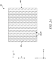
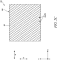
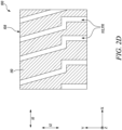
- FIGS 2A-2D illustrate schematic top views of the top layer 108.
- the top layer 108 includes a plurality of slots 112 extending at least partially from the top major surface 110 towards the major surface 104 of the substrate 102.
- at least one slot 112 from the plurality of slots 112 extends from the top major surface 110 to the bond coat layer 122.
- at least one slot 112 from the plurality of slots 112 extends from the top major surface 110 to the major surface 104 of the substrate 102 when the bond coat layer 122 is not present.
- the plurality of slots 112 are disposed throughout the length 102L of the substrate 102.
- At least one slot 170 from the plurality of slots 112 at least partially extends parallel to the transverse axis 12 of the major surface 104.
- the top layer 108 includes an array of slots 112 extending along the transverse axis 12 of the major surface 104.
- the plurality of slots 112 in the top layer 108 may be formed by at least one of laser cutting, water jet machining, abrasive machining, photolithography, and milling.
- At least one slot 172 from the plurality of slots 112 at least partially extends parallel to the longitudinal axis 10 of the major surface 104 as shown in Figure 2B .
- the coated article 100 includes only the slots 172 that extend parallel to the longitudinal axis 10.
- At least one slot 174 from the plurality of slots 112 at least partially extends obliquely relative to the longitudinal axis 10 as shown in Figure 2C .
- the coated article 100 includes only the slots 174 that extend obliquely relative to the longitudinal axis 10.
- the coated article 100 may include any combination of the slots 170, 172, 174.
- a portion of the slot 176 extends parallel to the transverse axis 12
- another portion of the slot 176 extends parallel to the longitudinal axis 10
- another portion of the slot 176 extends obliquely relative to the longitudinal axis 10.
- Any combination of the slots 170, 172, 174 may be utilized based on application requirements.
- the array of slots 112 may include linear rows of slots 112 or non-linear rows of slots 112 along the transverse axis 12. In some embodiments, the array of slots 112 may include linear rows and columns of slots 112 or non-linear rows and columns of slots 112 in the plane of the top major surface 110. In some embodiments, the array of slots 112 may include a triangular array of slots 112 in the plane of the top major surface 110. In some other embodiments, the array of slots 112 may include a hexagonal array of slots 112 in the plane of the top major surface 110.
- Figure 3 illustrates a schematic sectional side view of the coated article 100, according to another embodiment of the present disclosure.
- the major surface 104 of the substrate 102 has a predetermined shape (e.g., an arcuate shape).
- the protective coating 106 conforms to the predetermined shape of the major surface 104, and therefore, the protective coating 106 may be a conformal coating.
- the protective coating 106 (and the corresponding slots 112) may be aligned with the shape and form of the major surface 104 of the substrate 102.
- the major surface 104 of the substrate 102 may have different shapes and geometries based on application requirements and the protective coating 106 may conform to the corresponding shape and geometry of the major surface 104 of the substrate 102.
- the plurality of slots 112 have substantially parallel side walls.
- various geometries of the slots 112 can be possible based on application requirements and some examples are described later in the disclosure.
- the slots 112 may have a V-shaped and/or a U-shaped cross-section. It should be understood that the terms "V-shaped” and "U-shaped” describe a general geometry of the slots 112, while allowing for variations within the actual shape so as to not be a perfect V or U shape, respectively.
- the glazed layer 114 includes a plurality of cracks 118 disposed within the glazed layer 114. Each crack 118 from the plurality of cracks 118 is at least partially aligned with a corresponding slot 112 from the plurality of slots 112 in a plane 120 normal to the major surface 104 of the substrate 102.
- the plane 120 may correspond to the Y-Z plane.
- Figures 4A-4C illustrate schematic sectional side views of the coated article 100, according to different embodiments of the present disclosure.
- the plurality of cracks 118 are not shown for clarity.
- the glazed layer 114 includes a plurality of discrete sections 180.
- the top layer 108 includes a plurality of projecting sections 182. Each projecting section 182 from the plurality of projecting sections 182 is disposed between adjacent discrete sections 180 from the plurality of discrete sections 180.
- each projecting section 182 includes a non-glazed external surface 184 disposed adjacent to the glazed external surface 116.
- the protective coating 106 has the total thickness 124 from the glazed external surface 116 and/or the non-glazed external surface 184 to the major surface 104 of the substrate 102.
- the plurality of discrete sections 180 and the plurality of projecting sections 182 are disposed along the longitudinal axis 10. However, the plurality of discrete sections 180 and the plurality of projecting sections 182 may also be disposed along the transverse axis 12, in addition to the longitudinal axis 10 or otherwise.
- the protective coating 106 as shown in Figure 4A may allow increase in resistance to hot gas penetration (or calcium-magnesium-alumino-silicates propagation) to the substrate 102.
- the glazed layer 114 incudes a plurality of discrete patches 186, such that the plurality of discrete patches 186 are spaced apart from each other.
- the plurality of discrete patches 186 have a hexagonal shape (along the X-Y plane of the coated article 100). The hexagonal shape may allow close packing of the plurality of discrete patches 186 while being spaced apart from each other.
- the plurality of discrete patches 186 are disposed along the longitudinal axis 10.
- the plurality of discrete patches 186 may also be disposed along the transverse axis 12, in addition to the longitudinal axis 10 or otherwise.
- the glazed layer 114 at least partially fills one or more slots 112 from the plurality of slots 112.
- a material of the glazed layer 114 at least partially fills the one or more slots 112 from the plurality of slots 112 of the top layer 108.
- the glazed layer 114 at least partially fills the one or more slots 112 that are disposed along the longitudinal axis 10.
- the glazed layer 114 may also at least partially fill the one or more slots 112 described with reference to Figures 2B-2D .
- the protective coating 100 described with reference to Figures 4A-4C may allow reduction in a stiffness (or thermomechanical compliance) of the glazed layer 114 along the longitudinal axis 10 or the transverse axis 12, and/or may allow reduction in a ratio of a horizontal stiffness of the glazed layer 114 (along the longitudinal axis 10 or the transverse axis 12) to a vertical stiffness (along the Z-axis) of the glazed layer 114.
- thermomechanical compliance may be observed in the glazed layer 114 described with reference to Figure 4B as the plurality of discrete patches 186 are completely spaced apart from each other.
- thermomechanical compliance of the glazed layer 114 described with reference to Figure 4A as the material of the top layer 108 (which may typically be produced through spray deposition) may be more compliant than a material of the glazed layer 114, which is typically denser than the top layer 108.
- the least thermomechanical compliance may be observed in the glazed layer 114 described with reference to Figure 4C in which the material of the glazed layer 114 is continuous and fills the one or more slots 112 from the plurality of slots 112.
- a protective coating e.g., the protective coating 106
- a skilled person will appreciate that the methods and processes described hereinafter are not limited to this use and application only, and those methods and processes are described by way of an example for forming the protective coating using the described methods and processes.
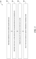
- Figure 5 is a flow chart illustrating a method 200 of forming a protective coating.
- the protective coating may be similar to the protective coating 106 (shown in Figure 1 ).
- the method 200 will be described hereinafter with reference to the coated article 100 of Figures 1-4C and Figures 6A-16 .
- Figures 6A-6B illustrate schematic views of the substrate 102. Specifically, Figure 6A illustrates a schematic sectional side view of the substrate 102 and Figure 6B illustrates a schematic perspective view of the substrate 102.
- the method 200 includes providing the substrate 102 including the major surface 104.
- the substrate 102 e.g., a component of a gas turbine engine
- the substrate 102 may be a high-temperature material, such as a superalloy.
- the substrate 102 may include any material based on application requirements.
- the substrate 102 may include silicon carbide-silicon carbide (SiC-SiC) matrix composites.
- the major surface 104 defines the longitudinal axis 10 along the length of the substrate 102 and the transverse axis 12 perpendicular to the longitudinal axis 10. It should be understood that the substrate 102 is schematically shown in Figures 6A-6B for illustrative purposes.
- Suitable alloys for the substrate 102 may include, but are not limited to, nickel-based superalloys, cobalt-based superalloys, iron-based superalloys, low sulphur nickel-based superalloys, low sulphur cobalt-based superalloys, low sulphur iron-based superalloys, etc.
- Such superalloys may typically include a polycrystalline structure, but may have portions with a single-crystal or directionally solidified crystalline structure.
- the substrate 102 may include nickel-based superalloys commercially available under the trademark Inconel ® .
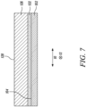
- Figure 7 illustrates a schematic sectional view of the substrate 102, the bond coat layer 122, and a top coat layer 126.
- the top coat layer 126 may include the same material as that of the top layer 108 (shown in Figures 1-4C ).
- the method 200 further includes providing the top coat layer 126 adjacent to the major surface 104 of the substrate 102.
- the top coat layer 126 includes a top coat surface 128 distal to the substrate 102.
- the top coat layer 126 may be further processed (e.g., heated) for forming the protective coating 106 (shown in Figure 1 ).
- the method 200 further includes providing the bond coat layer 122 between the top coat layer 126 and the major surface 104 of the substrate 102 prior to at least partially heating the top coat surface 128.
- the bond coat layer 122 may improve adhesion of the top coat layer 126 to the major surface 104 of the substrate 102 and may also reduce a rate of oxidation of the substrate 102.
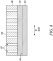
- Figure 8 illustrates a schematic sectional view of the substrate 102, the bond coat layer 122, and the top coat layer 126.
- the method 200 further includes forming the plurality of slots 112 in the top coat layer 126.
- Each slot 112 from the plurality of slots 112 extends at least partially from the top coat surface 128 towards the major surface 104 of the substrate 102 prior to at least partially heating the top coat surface 128.
- each slot 112 from the plurality of slots 112 extends from the top coat surface 128 to the bond coat layer 122.
- at least one slot 112 from the plurality of slots 112 extends from the top coat surface 128 to the bond coat layer 122 prior to at least partially heating the top coat surface 128.
- At least one slot 112 (e.g., the slot 170 shown in Figure 2A ) from the plurality of slots 112 at least partially extends parallel to the transverse axis 12 of the major surface 104.
- at least one slot 112 (e.g., the slot 172 shown in Figure 2B ) from the plurality of slots 112 at least partially extends parallel to the longitudinal axis 10.
- at least one slot 112 (e.g., the slot 174 shown in Figure 2C ) from the plurality of slots 112 at least partially extends obliquely relative to the longitudinal axis 10.
- forming the plurality of slots 112 in the top coat layer 126 includes at least one of laser cutting, water jet machining, abrasive machining, photolithography, milling, or a combination thereof.
- the slots 112 may be formed by cutting using a high-speed saw, a laser system, a high-speed water jet, a high-speed jet of fluid comprising abrasives, or combinations thereof.
- the plurality of slots 100 may traverse one or more layers of the top coat layer 126.
- Formation of the plurality of slots 112 in the top coat layer 126 may reduce thermal stress accumulation within the final protective coating 106 (shown in Figure 1 ) and may provide a material of the top coat layer 126 with a free space to expand, thereby improving strain tolerance (or thermomechanical compliance) of the final protective coating 106 (shown in Figure 1 ).
- This strain tolerance may be vital for components such as high-pressure turbine blades. In terms of thermal stress relaxation, it may be beneficial to create a through gap in the top coat layer 126 without affecting the bond coat layer 122 (when present).
- Figure 9 illustrates a schematic view of a laser ablation apparatus 150.
- the laser ablation apparatus 150 may be used for forming the plurality of slots 112 (shown in Figure 8 ) in the top coat layer 126 though laser ablation or laser cutting.
- the top coat layer 126 may have a varying thickness. Further, the top coat layer 126 is anisotropic with randomly distributed pores and interfaces. Consequently, laser ablation of the top coat layer 126 may generate slots 112 that are deeper or narrower than a required depth. Thus, when forming the plurality of slots 112 in the top coat layer 126, an appropriate laser ablation regime may be chosen.
- the laser cutting includes using an ultrashort pulse laser.
- the ultrashort pulse laser may be a picosecond laser or a femtosecond laser.
- the picosecond laser may prevent damage to the substrate 102 if a material of the top coat layer 126 has sufficiently low thermal conductivity.
- an ablation rate of the underlying bond coat layer 122 is negligible in comparison to the top coat layer 126. In other words, it may be safe to use lasers with a pulse duration equal to or shorter than tens of picoseconds.
- lasers with a pulse duration of femtosecond or shorter may also be utilized that may ensure correct metallurgical properties of the final protective coating 106 (shown in Figure 1 ).
- an energy density of the ultrashort pulse laser is less than or equal to about 2 J/mm 2 . This may induce least amount of thermal damage to the bond coat layer 122 during laser cutting.
- the laser ablation apparatus 150 includes a pulsed laser source 152 that generates a laser beam 153.
- the laser beam 153 includes the picosecond laser.
- the laser beam 153 passes through one or more beam expanders 156 that generates an expanded laser beam 158.
- the expanded laser beam 158 then falls on a galvanometer optical scanner 154 that reflects the expanded laser beam 158 towards a focusing lens 160.
- the expanded laser beam 158 further passes through the focusing lens 160 and forms a focussed laser beam 159 that is utilized for forming the plurality of slots 112 on the top coat layer 126 mounted on a stage 162.
- the stage 162 may be able to move along its respective x, y and z axes to generate a pattern or an array of slots 112 (shown in Figure 8 ) in the top coat layer 126.
- the top coat layer 126 may be manipulated by means of the stage 162 to generate different patterns of slots 112 (shown in Figure 8 ) in the top coat layer 126.
- the focussed laser beam 159 may have a pulse energy of 0.3 millijoules (mJ), a spot size of 35 ⁇ m, a scanning speed of 25 millimetres per second (mm/s), and a pulse repetition rate of 4 kilohertz (kHz).
- the plurality of slots 112 may be formed using a fixed laser architecture.
- the laser ablation apparatus 150 may include passive beam shaping means for shaping the focussed laser beam 159, such as a diffractive optical element, a masking, and an aspherical lens. Specific diffractive optical elements may be used based on application requirements.
- the laser ablation apparatus 150 may include active beam shaping means, such as a digital micromirror device (DMD), a liquid crystal spatial light modulator, a deformable mirror spatial light modulator, and an acoustic gradient lens.
- DMD digital micromirror device
- Figure 10 illustrates an enlarged schematic sectional view of the substrate 102 and the top coat layer 126.
- the top coat layer 126 includes a plurality of slots 132.
- the plurality of slots 132 may be similar to the plurality of slots 112 (shown in Figure 8 ).
- the bond coat layer 122 is not shown. However, the bond coat layer 122 may be disposed between the top coat layer 126 and the major surface 104 of the substrate 102.
- the method 200 further includes forming the plurality of slots 132 in the top coat layer 126.
- the plurality of slots 132 may be formed using the laser ablation apparatus 150 (shown in Figure 9 ).
- At least one slot 132 from the plurality of slots 132 extends from the top coat surface 128 to the major surface 104 of the substrate 102 prior to at least partially heating the top coat surface 128. Further, some slots 132 from the plurality of slots 132 do not extend to the major surface 104 of the substrate 102. In other words, some slots 132 from the plurality of slots 132 may not extend fully through a thickness of the top coat layer 126. For example, some slots 132 from the plurality of slots 132 may extend through about 20% to about 90% of a thickness of the top coat layer 126. In some embodiments, the plurality of slots 132 are formed in a cascading pattern.
- Figures 11A-11 D illustrate schematic sectional views of the substrate 102 and the top coat layer 126, according to different embodiments of the present disclosure. Specifically, Figure 11A illustrates a schematic sectional view of the substrate 102 and the top coat layer 126 including a plurality of slots 134; Figure 11B illustrates a schematic sectional view of the substrate 102 and the top coat layer 126 including a plurality of slots 136; Figure 11C illustrates a schematic sectional view of the substrate 102 and the top coat layer 126 including a plurality of slots 138; and Figure 11D illustrates a schematic sectional view of the substrate 102 and the top coat layer 126 including a plurality of slots 139.
- the bond coat layer 122 is not shown.
- the slots 134, 136, 138, 139 may be similar to the slots 112, 132 shown in Figures 1 and 10 , respectively. Further, each slot 134, 136, 138, 139 from the plurality of slots 134, 136, 138, 139 is at least partially defined by a pair of opposing walls 140 of the top coat layer 126.
- the laser ablation apparatus 150 shown in Figure 9
- the slot 134 has a rectangular cross-sectional area. Further, each wall 140 from the pair of walls 140 is perpendicular to the major surface 104 of the substrate 102.
- At least one wall 140 from the pair of walls 140 is inclined obliquely to the major surface 104 of the substrate 102 by an inclination angle 142.
- each of the pair of walls 140 is inclined obliquely to the major surface 104 of the substrate 102 by a corresponding inclination angle 142a, 142b.
- the corresponding inclination angles 142a, 142b may be equal to each other.
- the inclination angle 142 is less than 90 degrees or greater than 90 degrees.
- the inclination angles 142a, 142b are less than 90 degrees.
- the slot 136 has a trapezoidal cross-sectional area having a larger base towards the major surface 104 of the substrate 102.
- each wall 140 from the pair of walls 140 is inclined obliquely to the major surface 104 of the substrate 102 by the inclination angles 142a , 142b.
- the inclination angles 142a, 142b are greater than 90 degrees.
- the slot 138 has a trapezoidal cross-sectional area having a smaller base towards the major surface 104 of the substrate 102.
- the corresponding inclination angles 142a, 142b are different from each other.
- one of the walls 140 from the pair of walls 140 may be perpendicular to the major surface 104 of the substrate 102 while the other wall 140 from the pair of walls 140 may be inclined obliquely to the major surface 104 of the substrate 102 by the inclination angle 142 that is less than or greater than 90 degrees.
- appropriate geometry and shape of the plurality of slots 134, 136, 138, 139 may be tailored based on application requirements, component requirements, and thermomechanical behaviour that the component may witness during operating conditions. For instance, coated regions of an aerofoil of a high-pressure turbine blade which require higher strain compliance (due to a higher surface temperature during operating conditions) may be produced with a larger number of slots 134, 136, 138, 139 in the top coat layer 126. Moreover, the plurality of slots 134, 136, 138, 139 may be manufactured in a variety of arrays or structures to match a 3D strain compliance requirements of the component.
- the arrays and structures may include criss-cross shapes (i.e., overlapping slots), but may also include production of columns in a bespoke array (i.e., isolated "drilled" holes into the top coat layer 126).
- the inclination angles 142a, 142b may be controlled based on specific stress gradient directions within the final protective coating 106 (shown in Figure 1 ). For example, a stress distribution may be controlled via change in the inclination angles 142a, 142b. This may be produced on specific regions of a component to match the strain compliance requirements. Further, the inclination angles 142a, 142b and the arrays/patterns of slots 112 may be generated via a computer model of the component.
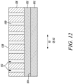
- Figure 12 illustrates a schematic sectional view of the substrate 102, the bond coat layer 122, and the top coat layer 126.
- the method 200 further includes filling at least one slot 112 from the plurality of slots 112 with a filling material 130 prior to at least partially heating the top coat surface 128.
- the at least one slot 112 from the plurality of slots 112 may be formed with an increased slot width since the at least one slot 112 may be filled with the filling material 130 later.
- the thermomechanical compliance of the protective coating 106 shown in Figure 1
- CMAS calcium-magnesium-alumino-silicate
- the filling material 130 is further filled in the at least one slot 112 from the plurality of slots 112 at least partially parallel to the transverse axis 12 of the major surface 104. In some embodiments, the filling material 130 may also be filled in the at least one slot 132, 134, 136, 138, 139 from the plurality of slots 132, 134, 136, 138, 139 (shown in Figures 10 and 11A-11D ) of the top coat layer 126.
- Examples of the filling material 130 may include zirconium dioxide (ZrO 2 ) stabilised with yttrium oxide (Y 2 O 3 ), cerium (IV) oxide (CeO 2 ), magnesium oxide (MgO), or calcium oxide (CaO).
- Other examples of the filling material 130 may include Gd 2 Zr 2 O 7 , La 2 Zr 2 O 7 , LaMgAl 11 O 19 , SrZrOs, titanium dioxide (TiO 2 ), scandium oxide (Sc 2 O 3 ), and aluminium oxide (Al 2 O 3 ).
- the filling material 130 may be a secondary material in the form of a powder, a colloid suspension, or a solution of the aforementioned materials.
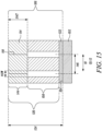
- Figure 13 illustrates a schematic sectional view of the substrate 102, the bond coat layer 122, and the top coat layer 126.
- the method 200 further includes at least partially heating the top coat surface 128 above a threshold temperature T, such that a first portion 144 of the top coat layer 126 extending from the top coat surface 128 at least partially melts.
- the method 200 further includes at least partially heating the top coat surface 128 above the threshold temperature T, such that a second portion 108 of the top coat layer 126 is not melted and includes at least a portion of each of the plurality of slots 112.
- the second portion 108 corresponds to the top layer 108 (shown in Figure 1 ), and hence, the same reference numeral 108 is used to refer to both.
- the threshold temperature T may correspond to a melting temperature of a material of the top coat layer 126.
- the top coat surface 128 may be at least partially heated using energy sources, such as a combustion torch or a plasma torch. In some embodiments, at least partially heating the top coat surface 128 further includes heating using a laser. In some embodiments, an energy density of the laser is less than or equal to about 5 J/mm 2 . In some embodiments, the laser is a pulsed laser having a pulse duration of at least 1 nanosecond or a continuous wave laser.
- the laser ablation apparatus 150 may also be used for at least partially heating the top coat surface 128 of the top coat layer 126.
- a spot size of a laser beam may be 400 ⁇ m and a scanning speed may be 50 mm/s.
- the top coat surface 128 may be at least partially heated to form an array of tracks extending along the longitudinal axis 10 of the major surface 104 of the substrate 102.
- a distance between the tracks along the transverse axis 12 may be about 320 ⁇ m.
- Figures 14 illustrates a schematic sectional view of the coated article 100 according to another embodiment of the present disclosure.
- the first portion 144 of the top coat layer 126 at least partially melts to form the glazed layer 114.
- the second portion 108 of the top coat layer 126 is disposed between the glazed layer 114 and the major surface 104 of the substrate 102.
- the second potion 108 is also interchangeably referred to herein as the top layer 108 (shown in Figure 1 ).
- the second portion 108 includes at least a portion of each of the plurality of slots 112.
- the second portion 108 may include at least a portion of each of the plurality of slots 132, 134, 136, 138, 139 (shown in Figures 10 and 11A-11D ).
- a density of the glazed layer 114 is greater than a density of the second portion 108 of the top coat layer 126.
- the glazed layer 114 includes the glazed external surface 116 distal to the second portion 108 of the top coat layer 126.
- the glazed layer 116 and the second portion 108 of the top coat layer 126 together form the protective coating 106 having the total thickness 124 from the glazed external surface 116 to the major surface 104 of the substrate 102.
- the coated article 100 further includes the bond coat layer 122. In such cases, the glazed layer 116, the second portion 108 of the top coat layer 126, and the bond coat layer 122 together form the protective coating 106.
- a thickness of the glazed layer 114 may be controlled based on laser beam parameters in order to optimize the protective coating 106 based on application requirements.
- Choice of energy and power density of the laser beam, as well as a scanning speed of the laser beam may be determined based on geometrical parameters of the slots 112.
- An amount of heating may be decreased with increased scanning speed, decreased laser power, increased laser beam diameter and/or decreasing power density of the laser beam.
- the glazed layer 114 includes the plurality of cracks 118 disposed within the glazed layer 114. Further, as discussed above, each crack 118 from the plurality of cracks 118 is at least partially aligned with the corresponding slot 112 from the plurality of slots 112 in the plane 120 normal to the major surface 104 of the substrate 102.
- the plurality of cracks 118 may be an inevitable result of at least partially heating the top coat surface 128 of the top coat layer 126 (comprising zirconia) above the threshold temperature T.
- the plurality of cracks 118 may be generated due to a high coefficient of thermal expansion and a high melting point of the material of the top coat layer 126, thus generating high tensile thermal stresses during cooling.
- the cooling is rapid, and the melted material of the top coat layer 126 disposed between the plurality of slots 112 solidifies rapidly as compared to the melted material of the top coat layer 126 above the slots 112.
- the plurality of cracks 118 may be generated in the glazed layer 114 and each crack 118 from the plurality of cracks 118 is at least partially aligned with the corresponding slot 112 as the accumulated thermoelastic strain between the columns 190 is higher.
- the top coat surface 128 is at least partially heated, such that the first portion 144 of the top coat layer 126 includes the plurality of discrete sections 180 and the second portion 108 (or the top layer 108 shown in Figure 4A ) of the top coat layer 126 includes the plurality of projecting sections 182.
- Each projecting section 182 from the plurality of projecting sections 182 is disposed between adjacent discrete sections 180 from the plurality of discrete sections 180.
- Each projecting section 182 includes the non-glazed external surface 184 disposed adjacent to the glazed external surface 116.
- the top coat surface 128 may be at least partially heated above the threshold temperature T, such that the first portion 144 of the top coat layer 126 at least partially melts (e.g., along the longitudinal axis 10) to form the plurality of discrete sections 180 in the glazed layer 114. Further, the first portion 144 of the top coat layer 126 may be at least partially or discontinuously heated to form the plurality of discrete sections 180. Moreover, each projecting section 182 of the top coat layer 126 is left non-glazed between the adjacent discrete sections 180 from the plurality of discrete sections 180 with the non-glazed external surface 184 of each projecting section 182 disposed adjacent to the glazed external surface 116.
- appropriate heating parameters may be chosen for generating the plurality of discrete sections 180.
- the plurality of discrete sections 180 may also be obtained through discontinuous heating by controlling a slot geometry, i.e., by controlling a width of the slots 112, or an opening of the slots 112.
- Figure 15 illustrates an enlarged schematic sectional view of a portion of the coated article 100.
- a width 112W of at least one slot 112 from the plurality of slots 112 is greater than or equal to about 1 ⁇ m.
- the width 112W of at least one slot 112 from the plurality of slots 112 may be greater than or equal to about 5 ⁇ m, greater than or equal to about 10 ⁇ m, greater than or equal to about 15 ⁇ m, greater than or equal to about 20 ⁇ m, or greater than or equal to about 25 ⁇ m.
- the width 112W of the at least one slot 112 from the plurality of slots 112 is less than the total thickness 124 of the protective coating 106.
- the width 112W of the at least one slot 112 from the plurality of slots 112 may be obtained based on desired strain tolerance of the protective coating 106.
- a minimum distance 146 between adjacent slots 112 from the plurality of slots 112 is greater than or equal to 10 ⁇ m. In some embodiments, the minimum distance 146 between the adjacent slots 112 is less than or equal to 10 times the total thickness 124 of the protective coating 106.
- the minimum distance 146 between the adjacent slots 112 may be chosen based on distance between the cracks 118 in the glazed layer 114 in order to connect the induced cracks 118 with the plurality of slots 112. A higher density of slots 112 may be beneficial, allowing to control a density of the cracks 118 with smaller width of the cracks 118. In some embodiments, a distance between the adjacent slots 112 may also be nonuniform in order to make some portions of the protective coating 106 more strain tolerant.
- the thickness 114T of the glazed layer 114 from the glazed external surface 116 to the second portion 108 of the top coat layer 126 is greater than or equal to 1 ⁇ m. In some embodiments, the thickness 114T of the glazed layer 114 is less than or equal to 90% of the total thickness 124 of the protective coating 106.
- the protective coating 106 having a relatively thin glazed layer 114 above the plurality of slots 112 may be able to accommodate greater thermomechanical stresses. Therefore, the strain tolerance of the protective coating 106 may be increased.
- a relatively thicker glazed layer 114 may reduce thermal conductivity and elemental transportation (e.g., oxygen) into an underlying structure of the protective coating 106.
- Figure 16 illustrates a schematic sectional view of the substrate 102, the bond coat layer 122, the top layer 108 and the glazed layer 114.
- the method 200 further includes cutting the glazed layer 114 to generate the plurality of discrete patches 186, such that the plurality of discrete patches 186 are spaced apart from each other.
- the glazed layer 114 may be cut using a laser 188 (e.g., of the laser ablation apparatus 150 shown in Figure 9 ).
- the laser 188 may be used to cut only the glazed layer 114 and not the entire thickness 124 of the protective coating 106.
- the plurality of discrete patches 186 may be generated after at least partially heating the top coat surface 128 (shown in Figure 13 ) to produce the glazed layer 114. In some embodiments, gaps between the plurality of discrete patches 186 may or may not align with the plurality of slots 112 or the plurality of slots 132, 134, 136, 138, 139 (shown in Figures 10 and 11A-11D ).
- the method 200 further includes heating the glazed layer 114 such that the glazed layer 114 at least partially melts and fills one or more slots 112, 132, 134, 136, 138, 139 (shown in Figures 10 , 11A-11D and 16 ) from the plurality of slots 112, 132, 134, 136, 138, 139.
- the glazed layer 114 may be remelted to at least partially fill the one or more slots 112 or the one or more slots 132, 134, 136, 138, 139 (shown in Figures 10 , 11A-11D and 16 ).
- the remelting process may be performed using the laser 188 (e.g., of the laser ablation apparatus 150 shown in Figure 9 ).
- the glazed layer 114 is cut or at least partially heated using the laser 188, however, any other suitable means may be chosen for cutting/heating the glazed layer 114 based on application requirements.
- appropriate operating parameters for the laser 188 may be chosen for obtaining the coated article 100 described with reference to Figures 4B and 4C .
- operating parameters may be controlled by decreasing an energy density of the laser 188 during the remelting process by either increasing a scanning speed of the laser 188 or increasing a diameter of the laser 188.
- the glazed layer 114 may reduce a surface roughness of the protective coating 106 and may improve its tribological properties. Additionally, the glazed layer 114 may provide a dense surficial layer resistant to erosion and surface damage, thereby improving mechanical properties of the protective coating 106. Further, the glazed layer 114 may decrease oxygen diffusion through the protective coating 106 due to densification. The glazed layer 114 may further increase reflectance in infrared spectrum range due to densification, thereby improving coating efficiency in terms of radiative heat transfer. In other words, the glazed layer 114 may potentially increase thermal insulation properties of the protective coating 106 against radiation.
- the protective coating 106 may exhibit increased thermal insulation due to presence of the plurality of slots 112, 132, 134, 136, 138, 139 within the protective coating 106, covered from the top with the glazed layer 114, which obstructs heat penetration to the plurality of slots 112. Deposition of the CMAS products within the plurality of slots 112 may be obstructed by the glazed layer 114, thereby improving CMAS resistance of the protective coating 106.
- the protective coating 106 of the present disclosure may combine advantages of both the techniques, i.e., surface remelting and segmented coatings (or coatings with gaps/slots).
Landscapes
- Chemical & Material Sciences (AREA)
- Engineering & Computer Science (AREA)
- Materials Engineering (AREA)
- Organic Chemistry (AREA)
- Mechanical Engineering (AREA)
- Chemical Kinetics & Catalysis (AREA)
- Metallurgy (AREA)
- Ceramic Engineering (AREA)
- Physics & Mathematics (AREA)
- Plasma & Fusion (AREA)
- Inorganic Chemistry (AREA)
- Structural Engineering (AREA)
- Thermal Sciences (AREA)
- General Engineering & Computer Science (AREA)
- Turbine Rotor Nozzle Sealing (AREA)
Abstract
Description
- The present disclosure relates to a coated article comprising a protective coating and a method of forming a protective coating.
- Thermal barrier coatings (TBCs) are often applied on surfaces of high temperature components, e.g., combustion chambers, turbine vanes, blades, etc., of gas turbine engines. Such TBCs may protect the coated components from oxidation at high temperatures and mechanical damage during operation.
- Some TBCs typically include a top layer (e.g., a ceramic layer) applied onto a metallic substrate. A bond coat layer, which is a metallic coating, is usually applied between the substrate and the top layer. The top layer generally has a porous microstructure with low resistance to mechanical loads, and thus, prone to damage from foreign objects. Further, due to thermal expansion in general, and thermal expansion coefficient mismatch between the substrate, the bond coat layer, and the top layer, TBCs are prone to spallation, particularly on components that undergo significant thermomechanical changes during operation. Deposition of calcium-magnesium-alumino-silicates (CMAS) products on TBC surfaces also reduces strain tolerance of TBCs, initiating cracks leading to spallation.
- Coating spallation may necessitate engine maintenance with coating reapplication. In order to decrease a time-of-flight cost and to reduce a frequency of coating reapplication, TBCs may typically be exposed to after-treatment techniques to improve properties of TBCs after application.
- Performance of TBCs may be improved via surface remelting (also known as surface glazing). Surface glazing may generate a dense resolidified microstructure leading to decrease in surface roughness and increase in corrosion/oxidation resistance. Further, erosion due to spallation is generally reduced due to increase in surface microhardness. However, surface glazing may introduce a network of cracks within the TBC perpendicular to the surface. Additionally, external stresses may increase at crack tips. Eventually, the cracks may propagate further and may lead to delamination of the TBC. Moreover, generated cracks are prone to becoming horizontal, which may initiate cohesive top layer spallation. Further, CMAS resistance is believed to be poor since the cracks are narrow in width and may be easily filled with molten CMAS, reducing strain tolerance of the TBC that is exposed to such environmental dust.
- In another approach, TBCs are typically provided with a pattern of gaps wide enough such that the molten CMAS may fill the gap but may not completely fill the gap. Further, the TBC may have improved thermal compliance due to the formed gaps, reducing thermal stress accumulation. However, the pattern of gaps may decrease a volumetric thermal insulation of the TBC since the gaps may be filled with hot gases, thereby heating a deeper layer of the TBC. Additionally, the pattern of gaps may increase oxygen diffusion through the TBC that may lead to faster growth of thermally grown oxides (TGOs) at an interface between the bond coat layer and the top layer. Further, generated gaps may represent a surface discontinuity leading to separation of a boundary layer of a flow of gas over the TBC. Thus, an improved coating system is desirable.
- According to a first aspect, there is provided a method of forming a protective coating. The method includes providing a substrate including a major surface. The method further includes providing a top coat layer adjacent to the major surface of the substrate. The top coat layer includes a top coat surface distal to the substrate. The method further includes forming a plurality of slots in the top coat layer. Each slot from the plurality of slots extends at least partially from the top coat surface towards the major surface of the substrate. The method further includes at least partially heating the top coat surface above a threshold temperature, such that a first portion of the top coat layer extending from the top coat surface at least partially melts to form a glazed layer. The method further includes at least partially heating the top coat surface above the threshold temperature, such that a second portion of the top coat layer disposed between the glazed layer and the major surface of the substrate is not melted and includes at least a portion of each of the plurality of slots. The glazed layer includes a glazed external surface. The glazed layer and the second portion of the top coat layer together form the protective coating having a total thickness from the glazed external surface to the major surface of the substrate.
- At least partially heating the top coat surface above the threshold temperature may lead to melting of the first portion of the top coat layer to form the glazed layer. Further, the second portion of the top coat layer is not melted and includes at least a portion of each of the plurality of slots. Formation of the plurality of slots in the top coat layer may reduce thermal stress accumulation within the protective coating and may provide a material of the top coat layer with a free space to expand, thereby improving strain (or thermomechanical) tolerance of the protective coating. Further, the protective coating may exhibit increased thermal insulation due to presence of the plurality of slots within the protective coating, covered from the top with the glazed layer, which obstructs heat penetration to the plurality of slots. Deposition of calcium-magnesium-alumino-silicates (CMAS) products within the plurality of slots may be obstructed by the glazed layer, thereby improving CMAS resistance of the protective coating.
- Thus, the protective coating of the present disclosure may combine advantages of both the techniques, i.e., surface remelting and segmented coatings (or coatings with gaps/slots). Additionally, the procedure of formation of the plurality of slots in the top coat layer and at least partially heating of the top coat surface may be performed using the same apparatus, e.g., a laser system.
- The glazed layer may reduce a surface roughness of the protective coating and may improve its tribological properties. Additionally, the glazed layer may provide a dense surficial layer resistant to erosion and surface damage, thereby improving mechanical properties of the protective coating. Further, the glazed layer may decrease oxygen diffusion through the protective coating due to densification. The glazed layer may further increase reflectance in infrared spectrum range due to densification and reduced surface roughness, thereby improving coating efficiency in terms of radiative heat transfer. In other words, the glazed layer may potentially increase thermal insulation properties of the protective coating against radiation. The glazed layer may further enable a visible change in optical properties of an external surface of the protective coating since the protective coating of the present disclosure may have a glossy, shiny metallic surface, with higher reflectivity in visible spectrum range.
- The proposed method may be utilized in an original equipment manufacturer (OEM) facility for producing the protective coating on the major surface of the substrate, or may be utilized during overhauling as a repair/salvage process, or may be utilized on-wing. In the latter case, the proposed method may be used to produce a patch of strain compliant coating on a delaminated component. Additionally, the proposed method may be used to provide strain compliance after a protective coating is deposited on the major surface of the substrate using other techniques. For example, the proposed method may be used to provide strain compliance in a protective coating which has been "sintered" during operation (i.e., columns of the protective coating produced using electron beam physical vapour deposition that have fused together due to environmental conditions, and thus, the strain compliance effect has been lost). This may enhance an operational life of the protective coating by ensuring that the protective coating may remain functional for more cycles.
- In some embodiments, the major surface defines a longitudinal axis along a length of the substrate and a transverse axis perpendicular to the longitudinal axis.
- In some embodiments, at least one slot from the plurality of slots at least partially extends parallel to the longitudinal axis.
- In some embodiments, at least one slot from the plurality of slots at least partially extends parallel to the transverse axis.
- In some embodiments, at least one slot from the plurality of slots at least partially extends obliquely relative to the longitudinal axis.
- In some embodiments, the major surface of the substrate has a predetermined shape. In some embodiments, the protective coating conforms to the predetermined shape of the major surface. Thus, the protective coating may be aligned with the shape and form of the major surface of the substrate.
- In some embodiments, forming the plurality of slots in the top coat layer includes at least one of laser cutting, water jet machining, abrasive machining, photolithography, and milling.
- In some embodiments, the laser cutting includes using an ultrashort pulse laser. The ultrashort pulse laser may prevent damage to the substrate if a material of the top coat layer has sufficiently low thermal conductivity. In some examples, the ultrashort pulse laser may be a picosecond laser or a femtosecond laser. In the picosecond regime, ablation rate of underlying bond coat layer (if present) is negligible in comparison to the top coat layer. In other words, it is safe to use lasers with laser pulses equal to or shorter than tens of picoseconds.
- In some embodiments, an energy density of the ultrashort pulse laser is less than or equal to about 2 J/mmc2. This may induce least amount of thermal damage to the underlying bond coat layer during laser cutting.
- In some embodiments, a width of at least one slot from the plurality of slots is greater than or equal to about 1 µm. Width of the at least one slot from the plurality of slots may be determined based on desired strain tolerance of the protective coating.
- In some embodiments, the width of the at least one slot from the plurality of slots is less than the total thickness of the protective coating.
- In some embodiments, a thickness of the glazed layer from the glazed external surface to the second portion of the top coat layer is greater than or equal to 1 µm. A relatively thicker glazed layer may reduce thermal conductivity and elemental transportation (e.g., oxygen) into the underlying structure of the protective coating. In some embodiments, the thickness of the glazed layer is less than or equal to 90% of the total thickness of the protective coating.
- In some embodiments, a minimum distance between adjacent slots from the plurality of slots is greater than or equal to 10 µm. The minimum distance between adjacent slots may be chosen based on distance between induced cracks in the glazed layer in order to connect the cracks with the plurality of slots. A higher density of slots may be beneficial, allowing to control a density of cracks with smaller width of the cracks.
- In some embodiments, the minimum distance between the adjacent slots is less than or equal to 10 times the total thickness of the protective coating.
- In some embodiments, the method further includes filling at least one slot from the plurality of slots with a filling material prior to at least partially heating the top coat surface. Thus, the at least one slot from the plurality of slots may be formed with an increased slot width since the at least one slot may be filled with the filling material later. In some examples, the filling material may be a secondary material in the form of a powder, a colloid suspension, or a solution. Thus, the thermomechanical compliance of the protective coating may be improved with the increased slot width. Further, this may enhance CMAS resistance of the protective coating due to reduction of hollow spaces, i.e., the slots being filled with the filling material. Additionally, this may reduce thermal stresses (due to thermally grown oxides) accumulated at the interface between the bond coat layer and the top coat layer due to the plurality of slots being filled with the filling material.
- In some embodiments, at least one slot from the plurality of slots extends from the top coat surface to the major surface of the substrate prior to at least partially heating the top coat surface.
- In some embodiments, the method further includes providing a bond coat layer between the top coat layer and the major surface of the substrate prior to at least partially heating the top coat surface. The bond coat layer may improve adhesion of the top coat layer to the major surface of the substrate and may also reduce a rate of oxidation of the substrate.
- In some embodiments, at least one slot from the plurality of slots extends from the top coat surface to the bond coat layer prior to at least partially heating the top coat surface.
- In some embodiments, each slot from the plurality of slots is at least partially defined by a pair of opposing walls of the top coat layer.
- In some embodiments, each wall from the pair of walls is perpendicular to the major surface of the substrate.
- In some embodiments, at least one wall from the pair of walls is inclined obliquely to the major surface of the substrate by an inclination angle. The inclination angle is less than 90 degrees or greater than 90 degrees. Appropriate geometry of the plurality of slots may be chosen based on desired thermomechanical compliance of the protective coating.
- In some embodiments, each of the pair of walls is inclined obliquely to the major surface of the substrate by a corresponding inclination angle.
- In some embodiments, the corresponding inclination angles are different from each other.
- In some embodiments, the glazed layer includes a plurality of cracks disposed within the glazed layer. Each crack from the plurality of cracks is at least partially aligned with a corresponding slot from the plurality of slots in a plane normal to the major surface of the substrate. A tendency of the crack to become horizontal may be restricted since each crack from the plurality of cracks is arrested at the corresponding slot. Further, a width of the crack may be controlled based on the minimum distance between the adjacent slots.
- In some embodiments, a density of the glazed layer is greater than a density of the second portion of the top coat layer. Presence of densified glazed layer may obstruct heat penetration to the plurality of slots and the underlying structure. Further, the glazed layer may provide a dense surficial layer that is resistant to erosion and surface damage along with improved surface roughness of the protective coating.
- In some embodiments, at least partially heating the top coat surface further includes heating using a laser. In some embodiments, an energy density of the laser is less than or equal to about 5 J/mm2.
- In some embodiments, the laser is a pulsed laser having a pulse duration of at least 1 nanosecond or a continuous wave laser.
- In some embodiments, the top coat surface is at least partially heated, such that the first portion of the top coat layer includes a plurality of discrete sections and the second portion of the top coat layer includes a plurality of projecting sections. Each projecting section from the plurality of projecting sections is disposed between adjacent discrete sections from the plurality of discrete sections. Each projecting section includes a non-glazed external surface disposed adjacent to the glazed external surface. This may allow reduction in a stiffness of the glazed layer since a material of the top coat layer (which may typically be produced through spray deposition) may be more compliant than a material of the glazed layer which is typically denser than the top coat layer.
- In some embodiments, the method further includes cutting the glazed layer to generate a plurality of discrete patches, such that the plurality of patches are spaced apart from each other. Cutting the glazed layer to generate the plurality of discrete patches may allow reduction in the stiffness of the glazed layer and/or may allow reduction in a ratio of a horizontal stiffness of the glazed layer to a vertical stiffness of the glazed layer.
- In some embodiments, the method further includes heating the glazed layer such that the glazed layer at least partially melts and fills one or more slots from the plurality of slots.
- According to a second aspect, there is provided a coated article. The coated article includes a substrate including a major surface. The coated article further includes a protective coating disposed adjacent to the major surface of the substrate. The protective coating includes a top layer disposed adjacent to the major surface of the substrate. The top layer includes a top major surface distal to the major surface of the substrate and a plurality of slots extending at least partially from the top major surface towards the major surface of the substrate. The protective coating further includes a glazed layer disposed directly adjacent to the top major surface of the top layer and including a glazed external surface. The protective coating has a total thickness from the glazed external surface to the major surface of the substrate.
- In some embodiments, a density of the glazed layer is greater than a density of the top layer.
- In some embodiments, the coated article further includes a bond coat layer disposed between the top layer and the major surface of the substrate.
- In some embodiments, the glazed layer includes a plurality of cracks disposed within the glazed layer. Each crack from the plurality of cracks is at least partially aligned with a corresponding slot from the plurality of slots in a plane normal to the major surface of the substrate.
- In some embodiments, the major surface defines a longitudinal axis along a length of the substrate and a transverse axis perpendicular to the longitudinal axis.
- In some embodiments, at least one slot from the plurality of slots at least partially extends parallel to the longitudinal axis.
- In some embodiments, at least one slot from the plurality of slots at least partially extends parallel to the transverse axis.
- In some embodiments, at least one slot from the plurality of slots at least partially extends obliquely relative to the longitudinal axis.
- In some embodiments, the major surface of the substrate has a predetermined shape. In some embodiments, the protective coating conforms to the predetermined shape of the major surface.
- In some embodiments, the glazed layer includes a plurality of discrete sections. The top layer includes a plurality of projecting sections. Each projecting section from the plurality of projecting sections is disposed between adjacent discrete sections from the plurality of discrete sections. Each projecting section includes a non-glazed external surface disposed adjacent to the glazed external surface.
- In some embodiments, the glazed layer includes a plurality of discrete patches, such that the plurality of patches are spaced apart from each other.
- In some embodiments, the glazed layer at least partially fills one or more slots from the plurality of slots.
- The skilled person will appreciate that except where mutually exclusive, a feature or parameter described in relation to any one of the above aspects may be applied to any other aspect. Furthermore, except where mutually exclusive, any feature or parameter described herein may be applied to any aspect and/or combined with any other feature or parameter described herein.
- Embodiments will now be described by way of example only, with reference to the Figures, in which:
-
Figure 1 is a schematic sectional side view of a coated article, according to an embodiment of the present disclosure; -
Figures 2A-2D are schematic top views of a top layer of the coated article ofFigure 1 , according to an embodiment of the present disclosure; -
Figure 3 is a schematic sectional side view of the coated article, according to another embodiment of the present disclosure; -
Figures 4A-4C are schematic sectional side views of the coated article, according to different embodiments of the present disclosure; -
Figure 5 is a flowchart illustrating a method of forming a protective coating, according to an embodiment of the present disclosure; -
Figure 6A is a schematic sectional side view of a substrate, according to an embodiment of the present disclosure; -
Figure 6B is a schematic perspective view of the substrate of Figure 5A, according to an embodiment of the present disclosure; -
Figure 7 is a schematic sectional view of a top coat layer, a bond coat layer, and the substrate, according to an embodiment of the present disclosure; -
Figure 8 is a schematic sectional view of the top coat layer, the bond coat layer, and the substrate, where a plurality of slots is formed in the top coat layer, according to an embodiment of the present disclosure; -
Figure 9 is a schematic view of a laser ablation apparatus, according to an embodiment of the present disclosure; -
Figure 10 is a schematic sectional side view of the top coat layer and the substrate, according to an embodiment of the present disclosure; -
Figures 11A-11D are schematic sectional side views of the top coat layer and the substrate, according to different embodiments of the present disclosure; -
Figure 12 is a schematic sectional side view of the top coat layer, the bond coat layer, and the substrate, where the slots are filled with a filling material, according to an embodiment of the present disclosure; -
Figure 13 is a schematic sectional side view of the top coat layer, the bond coat layer, and the substrate, where a top coat surface of the top coat layer is at least partially heated above a threshold temperature, according to another embodiment of the present disclosure; -
Figure 14 is a schematic sectional side view of the coated article, according to another embodiment of the present disclosure; -
Figure 15 is an enlarged sectional side view of a portion of the coated article ofFigure 13 , according to an embodiment of the present disclosure; and -
Figure 16 is a schematic sectional side view of the substrate, the bond coat layer, the top layer and a glazed layer, according to an embodiment of the present disclosure. - Aspects and embodiments of the present disclosure will now be discussed with reference to the accompanying figures. Further aspects and embodiments will be apparent to those skilled in the art.
- Chemical elements are discussed in the present disclosure using their common chemical abbreviations, such as commonly found on a periodic table of elements. For example, hydrogen is represented by its common chemical abbreviation H; helium is represented by its common chemical abbreviation He; and so forth.
-
Figure 1 illustrates a schematic sectional side view of acoated article 100. Thecoated article 100 defines mutually orthogonal X, Y, and Z-axes. The X and Y-axes are in-plane axes of thecoated article 100, and the Z-axis is disposed along a thickness of thecoated article 100. In other words, the X and Y-axes are disposed along a plane of thecoated article 100, and the Z-axis is perpendicular to the plane of thecoated article 100. - In some embodiments, the
coated article 100 may be a part or a portion of a gas turbine engine. Thecoated article 100 includes asubstrate 102 including amajor surface 104. A portion of thesubstrate 102 may be shown inFigure 1 for illustrative purposes. In some embodiments, thesubstrate 102 may be a high-temperature material, such as a superalloy. However, thesubstrate 102 may include any material based on application requirements. In some examples, thesubstrate 102 may include silicon carbide-silicon carbide (SiC-SiC) matrix composites. - In some embodiments, the
major surface 104 defines alongitudinal axis 10 along alength 102L of thesubstrate 102 and atransverse axis 12 perpendicular to thelongitudinal axis 10. In some embodiments, thelongitudinal axis 10 and thetransverse axis 12 are disposed along the plane of thecoated article 100. In some embodiments, thelongitudinal axis 10 is substantially parallel to the X-axis, and thetransverse axis 12 is substantially parallel to the Y-axis. - The
coated article 100 further includes aprotective coating 106 disposed adjacent to themajor surface 104 of thesubstrate 102. In some embodiments, theprotective coating 106 may be a thermal barrier coating (TBC) or an environmental barrier coating (EBC) that protects thesubstrate 102 from hot gases and may increase an operational life of the substrate by preventing failure due to oxidation and thermomechanical fatigue. As used herein, the terms "TBC", "TBCs", "EBC" or "EBCs", generally refer to stabilized ceramics that may sustain a fairly high temperature gradient such that the substrate 102 (e.g., a metallic component) may be operated at temperatures higher than a melting point of a material of thesubstrate 102. In some embodiments, theprotective coating 106 may be a multilayered coating. In some embodiments, thecoated article 100 may further include one or more layers (e.g., EBCs, TBCs, abradable layers, etc.) above or below theprotective coating 106. In some embodiments, theprotective coating 106 may cover an entire extent of themajor surface 104 in the plane of thecoated article 100. - The
protective coating 106 includes atop layer 108 disposed adjacent to themajor surface 104 of thesubstrate 102. Thetop layer 108 has athickness 108T. In some embodiments, thetop layer 108 may include a ceramic material, such as yttria-stabilized zirconia (YSZ), however, any other ceramic material may be utilized. Alternative stabilizers for tetragonal phase in zirconia may include cerium (IV) oxide (CeO2), magnesium oxide (MgO), calcium oxide (CaO), or other oxides. In some embodiments, YSZ may include additional elements such as, but are not limited to, titanium dioxide (TiO2), scandium oxide (Sc2O3), aluminium oxide (Al2O3), etc. In some embodiments, multi-layer and composition-graded protective coatings composed of the aforementioned materials may be also utilized. - Other examples of materials for the
top layer 108 may include, but are not limited to, gadolinium zirconate (Gd2Zr2O7), lanthanum zirconate (La2Zr2O7), lanthanum magnesium hexa-aluminate (LaMgAl11O19), strontium zirconium trioxide (SrZrOs). Thetop layer 108 further includes a topmajor surface 110 distal to themajor surface 104 of thesubstrate 102. - In some embodiments, the
top layer 108 may include one or more materials from a group consisting of yttrium monosilicate, yttrium disilicate, rare-earth silicates (both rare-earth monosilicates and rare-earth disilicates), alkaline-earth aluminosilicates, such as barium-strontium-aluminosilicate, niobium oxide, tantalum oxide, zirconium oxide, hafnium oxide, yttrium oxide, titanium oxide, mullite, rare-earth oxides, magnesium-spinel (Mg-spinel), such as magnesium aluminate spinel (MgAl2O4 spinel), and mixtures and compounds thereof. In some other embodiments, thetop layer 108 may include a variety of metal sources including, but are not limited to, aluminium, chromium, tantalum, niobium, silicon, molybdenum, hafnium, titanium, zirconium, platinum, palladium, gold, and mixtures and alloys thereof. - The
protective coating 106 further includes aglazed layer 114 disposed directly adjacent to the topmajor surface 110 of thetop layer 108. Theglazed layer 114 includes a glazedexternal surface 116. Theglazed layer 114 has athickness 114T from the glazedexternal surface 116 to thetop layer 108. In some embodiments, thethickness 114T of theglazed layer 114 from the glazedexternal surface 116 to the topmajor surface 110 of thetop layer 108 may be greater than or equal to 1 micrometre (µm). In some embodiments, a density of theglazed layer 114 is greater than a density of thetop layer 108. - In some embodiments, the
protective coating 106 further includes abond coat layer 122 disposed between thetop layer 108 and themajor surface 104 of thesubstrate 102. In some embodiments, thebond coat layer 122 may be an oxidation-resistant metallic layer, for example, an aluminium-based layer. In some embodiments, thebond coat layer 122 may include an aluminium containing alloy, such as MCrAlY, where M = Nickel (Ni) and/or Cobalt (Co), or an aluminium-based intermetallic, such as nickel aluminide, containing varying amounts of platinum (Pt) and/or rare earth elements, such hafnium (Hf). In some embodiments, thebond coat 122 may include silica. - In some embodiments, the
top layer 108 or thebond coat layer 122 may be formed using vapour deposition techniques or diffusion-based processes. In some embodiments, thebond coat layer 122 may enhance adhesion of thetop layer 108 to themajor surface 104 of thesubstrate 102 and may reduce a rate of oxidation of thesubstrate 102. - In some embodiments, the
bond coat layer 122 may form a thin thermally grown (aluminium) oxide (TGO) layer when thebond coat layer 122 is exposed to oxygen at high temperatures. In some embodiments, YSZ as thetop layer 108 is an oxygen-transparent material, i.e., it allows oxygen atoms to penetrate through thetop layer 108. These atoms reaching thebond coat layer 122 may chemically react with aluminium to form aluminium oxides (Al2O3) at the interface between thebond coat layer 122 and thetop layer 108 that is generally referred to as the TGO layer. Such a TGO layer may further impede oxidation and hot corrosion of thesubstrate 102. - The
bond coat layer 122 has athickness 122T from thetop layer 108 to themajor surface 104 of thesubstrate 102. Further, theprotective coating 106 has atotal thickness 124 from the glazedexternal surface 116 to themajor surface 104 of thesubstrate 102. In other words, thetotal thickness 124 is equal to sum of thethicknesses top layer 108, theglazed layer 114, and thebond coat layer 122, respectively. In some embodiments, thebond coat layer 122 may be optional. In such cases, thetotal thickness 124 of theprotective coating 106 is equal to sum of thethicknesses top layer 108 and theglazed layer 114, respectively. In some embodiments, thethickness 114T of theglazed layer 114 is less than or equal to 90% of thetotal thickness 124 of theprotective coating 106. -
Figures 2A-2D illustrate schematic top views of thetop layer 108. Referring toFigures 1 and2 , thetop layer 108 includes a plurality ofslots 112 extending at least partially from the topmajor surface 110 towards themajor surface 104 of thesubstrate 102. Specifically, as shown inFigure 1 , at least oneslot 112 from the plurality ofslots 112 extends from the topmajor surface 110 to thebond coat layer 122. In some embodiments, at least oneslot 112 from the plurality ofslots 112 extends from the topmajor surface 110 to themajor surface 104 of thesubstrate 102 when thebond coat layer 122 is not present. In some embodiments, the plurality ofslots 112 are disposed throughout thelength 102L of thesubstrate 102. - As shown in
Figure 2A , in some embodiments, at least one slot 170 from the plurality ofslots 112 at least partially extends parallel to thetransverse axis 12 of themajor surface 104. In some embodiments, thetop layer 108 includes an array ofslots 112 extending along thetransverse axis 12 of themajor surface 104. In some embodiments, the plurality ofslots 112 in thetop layer 108 may be formed by at least one of laser cutting, water jet machining, abrasive machining, photolithography, and milling. - Alternatively, at least one slot 172 from the plurality of
slots 112 at least partially extends parallel to thelongitudinal axis 10 of themajor surface 104 as shown inFigure 2B . In the illustrated embodiment ofFigure 2B , thecoated article 100 includes only the slots 172 that extend parallel to thelongitudinal axis 10. - Further, in some embodiments, at least one slot 174 from the plurality of
slots 112 at least partially extends obliquely relative to thelongitudinal axis 10 as shown inFigure 2C . In the illustrated embodiment ofFigure 2C , thecoated article 100 includes only the slots 174 that extend obliquely relative to thelongitudinal axis 10. - It should be understood that the
coated article 100 may include any combination of the slots 170, 172, 174. For example, as shown inFigure 2D , a portion of the slot 176 extends parallel to thetransverse axis 12, another portion of the slot 176 extends parallel to thelongitudinal axis 10, and another portion of the slot 176 extends obliquely relative to thelongitudinal axis 10. Any combination of the slots 170, 172, 174 may be utilized based on application requirements. - In some embodiments, the array of
slots 112 may include linear rows ofslots 112 or non-linear rows ofslots 112 along thetransverse axis 12. In some embodiments, the array ofslots 112 may include linear rows and columns ofslots 112 or non-linear rows and columns ofslots 112 in the plane of the topmajor surface 110. In some embodiments, the array ofslots 112 may include a triangular array ofslots 112 in the plane of the topmajor surface 110. In some other embodiments, the array ofslots 112 may include a hexagonal array ofslots 112 in the plane of the topmajor surface 110. -
Figure 3 illustrates a schematic sectional side view of thecoated article 100, according to another embodiment of the present disclosure. In the illustrated embodiment ofFigure 3 , themajor surface 104 of thesubstrate 102 has a predetermined shape (e.g., an arcuate shape). In some embodiments, theprotective coating 106 conforms to the predetermined shape of themajor surface 104, and therefore, theprotective coating 106 may be a conformal coating. Thus, the protective coating 106 (and the corresponding slots 112) may be aligned with the shape and form of themajor surface 104 of thesubstrate 102. In other words, themajor surface 104 of thesubstrate 102 may have different shapes and geometries based on application requirements and theprotective coating 106 may conform to the corresponding shape and geometry of themajor surface 104 of thesubstrate 102. - In the illustrated embodiment of
Figure 1 , the plurality ofslots 112 have substantially parallel side walls. Alternatively, various geometries of theslots 112 can be possible based on application requirements and some examples are described later in the disclosure. In some embodiments, theslots 112 may have a V-shaped and/or a U-shaped cross-section. It should be understood that the terms "V-shaped" and "U-shaped" describe a general geometry of theslots 112, while allowing for variations within the actual shape so as to not be a perfect V or U shape, respectively. - In some embodiments, the
glazed layer 114 includes a plurality ofcracks 118 disposed within theglazed layer 114. Eachcrack 118 from the plurality ofcracks 118 is at least partially aligned with acorresponding slot 112 from the plurality ofslots 112 in aplane 120 normal to themajor surface 104 of thesubstrate 102. Theplane 120 may correspond to the Y-Z plane. -
Figures 4A-4C illustrate schematic sectional side views of thecoated article 100, according to different embodiments of the present disclosure. In the illustrated embodiments ofFigures 4A-4C , the plurality ofcracks 118 are not shown for clarity. - Referring to
Figure 4A , in some embodiments, theglazed layer 114 includes a plurality ofdiscrete sections 180. Thetop layer 108 includes a plurality of projectingsections 182. Each projectingsection 182 from the plurality of projectingsections 182 is disposed between adjacentdiscrete sections 180 from the plurality ofdiscrete sections 180. - In some embodiments, each projecting
section 182 includes a non-glazedexternal surface 184 disposed adjacent to the glazedexternal surface 116. Thus, in the illustrated embodiment ofFigure 4A , theprotective coating 106 has thetotal thickness 124 from the glazedexternal surface 116 and/or the non-glazedexternal surface 184 to themajor surface 104 of thesubstrate 102. - In the illustrated embodiment of
Figure 4A , the plurality ofdiscrete sections 180 and the plurality of projectingsections 182 are disposed along thelongitudinal axis 10. However, the plurality ofdiscrete sections 180 and the plurality of projectingsections 182 may also be disposed along thetransverse axis 12, in addition to thelongitudinal axis 10 or otherwise. Theprotective coating 106 as shown inFigure 4A may allow increase in resistance to hot gas penetration (or calcium-magnesium-alumino-silicates propagation) to thesubstrate 102. - Referring to
Figure 4B , in some embodiments, theglazed layer 114 incudes a plurality ofdiscrete patches 186, such that the plurality ofdiscrete patches 186 are spaced apart from each other. In some embodiments, the plurality ofdiscrete patches 186 have a hexagonal shape (along the X-Y plane of the coated article 100). The hexagonal shape may allow close packing of the plurality ofdiscrete patches 186 while being spaced apart from each other. In the illustrated embodiment ofFigure 4B , the plurality ofdiscrete patches 186 are disposed along thelongitudinal axis 10. However, the plurality ofdiscrete patches 186 may also be disposed along thetransverse axis 12, in addition to thelongitudinal axis 10 or otherwise. - Referring to
Figure 4C , in some embodiments, theglazed layer 114 at least partially fills one ormore slots 112 from the plurality ofslots 112. In other words, a material of theglazed layer 114 at least partially fills the one ormore slots 112 from the plurality ofslots 112 of thetop layer 108. In the illustrated embodiment ofFigure 4C , theglazed layer 114 at least partially fills the one ormore slots 112 that are disposed along thelongitudinal axis 10. However, theglazed layer 114 may also at least partially fill the one ormore slots 112 described with reference toFigures 2B-2D . - The
protective coating 100 described with reference toFigures 4A-4C may allow reduction in a stiffness (or thermomechanical compliance) of theglazed layer 114 along thelongitudinal axis 10 or thetransverse axis 12, and/or may allow reduction in a ratio of a horizontal stiffness of the glazed layer 114 (along thelongitudinal axis 10 or the transverse axis 12) to a vertical stiffness (along the Z-axis) of theglazed layer 114. - In some embodiments, the highest thermomechanical compliance may be observed in the
glazed layer 114 described with reference toFigure 4B as the plurality ofdiscrete patches 186 are completely spaced apart from each other. This is followed by thermomechanical compliance of theglazed layer 114 described with reference toFigure 4A as the material of the top layer 108 (which may typically be produced through spray deposition) may be more compliant than a material of theglazed layer 114, which is typically denser than thetop layer 108. The least thermomechanical compliance may be observed in theglazed layer 114 described with reference toFigure 4C in which the material of theglazed layer 114 is continuous and fills the one ormore slots 112 from the plurality ofslots 112. - In the disclosure, embodiments are described hereinafter in detail for a method of forming a protective coating (e.g., the protective coating 106). A skilled person will appreciate that the methods and processes described hereinafter are not limited to this use and application only, and those methods and processes are described by way of an example for forming the protective coating using the described methods and processes.
-
Figure 5 is a flow chart illustrating amethod 200 of forming a protective coating. In some embodiments, the protective coating may be similar to the protective coating 106 (shown inFigure 1 ). Themethod 200 will be described hereinafter with reference to thecoated article 100 ofFigures 1-4C andFigures 6A-16 . -
Figures 6A-6B illustrate schematic views of thesubstrate 102. Specifically,Figure 6A illustrates a schematic sectional side view of thesubstrate 102 andFigure 6B illustrates a schematic perspective view of thesubstrate 102. Referring now toFigures 5 and6A-6B , atstep 202, themethod 200 includes providing thesubstrate 102 including themajor surface 104. In some embodiments, the substrate 102 (e.g., a component of a gas turbine engine) may be a high-temperature material, such as a superalloy. However, thesubstrate 102 may include any material based on application requirements. In some examples, thesubstrate 102 may include silicon carbide-silicon carbide (SiC-SiC) matrix composites. In some embodiments, themajor surface 104 defines thelongitudinal axis 10 along the length of thesubstrate 102 and thetransverse axis 12 perpendicular to thelongitudinal axis 10. It should be understood that thesubstrate 102 is schematically shown inFigures 6A-6B for illustrative purposes. - Suitable alloys for the
substrate 102 may include, but are not limited to, nickel-based superalloys, cobalt-based superalloys, iron-based superalloys, low sulphur nickel-based superalloys, low sulphur cobalt-based superalloys, low sulphur iron-based superalloys, etc. Such superalloys may typically include a polycrystalline structure, but may have portions with a single-crystal or directionally solidified crystalline structure. In some embodiments, thesubstrate 102 may include nickel-based superalloys commercially available under the trademark Inconel®. -
Figure 7 illustrates a schematic sectional view of thesubstrate 102, thebond coat layer 122, and atop coat layer 126. In some embodiments, thetop coat layer 126 may include the same material as that of the top layer 108 (shown inFigures 1-4C ). Referring now toFigures 5 and7 , atstep 204, themethod 200 further includes providing thetop coat layer 126 adjacent to themajor surface 104 of thesubstrate 102. Thetop coat layer 126 includes atop coat surface 128 distal to thesubstrate 102. - In some embodiments, the
top coat layer 126 may be further processed (e.g., heated) for forming the protective coating 106 (shown inFigure 1 ). Themethod 200 further includes providing thebond coat layer 122 between thetop coat layer 126 and themajor surface 104 of thesubstrate 102 prior to at least partially heating thetop coat surface 128. Thebond coat layer 122 may improve adhesion of thetop coat layer 126 to themajor surface 104 of thesubstrate 102 and may also reduce a rate of oxidation of thesubstrate 102. -
Figure 8 illustrates a schematic sectional view of thesubstrate 102, thebond coat layer 122, and thetop coat layer 126. Referring now toFigures 5 and8 , atstep 206, themethod 200 further includes forming the plurality ofslots 112 in thetop coat layer 126. Eachslot 112 from the plurality ofslots 112 extends at least partially from thetop coat surface 128 towards themajor surface 104 of thesubstrate 102 prior to at least partially heating thetop coat surface 128. Specifically, eachslot 112 from the plurality ofslots 112 extends from thetop coat surface 128 to thebond coat layer 122. In some other embodiments, at least oneslot 112 from the plurality ofslots 112 extends from thetop coat surface 128 to thebond coat layer 122 prior to at least partially heating thetop coat surface 128. - In some embodiments, at least one slot 112 (e.g., the slot 170 shown in
Figure 2A ) from the plurality ofslots 112 at least partially extends parallel to thetransverse axis 12 of themajor surface 104. Alternatively, at least one slot 112 (e.g., the slot 172 shown inFigure 2B ) from the plurality ofslots 112 at least partially extends parallel to thelongitudinal axis 10. Alternatively, at least one slot 112 (e.g., the slot 174 shown inFigure 2C ) from the plurality ofslots 112 at least partially extends obliquely relative to thelongitudinal axis 10. - In some embodiments, forming the plurality of
slots 112 in thetop coat layer 126 includes at least one of laser cutting, water jet machining, abrasive machining, photolithography, milling, or a combination thereof. For example, theslots 112 may be formed by cutting using a high-speed saw, a laser system, a high-speed water jet, a high-speed jet of fluid comprising abrasives, or combinations thereof. In some embodiments, the plurality ofslots 100 may traverse one or more layers of thetop coat layer 126. - Formation of the plurality of
slots 112 in thetop coat layer 126 may reduce thermal stress accumulation within the final protective coating 106 (shown inFigure 1 ) and may provide a material of thetop coat layer 126 with a free space to expand, thereby improving strain tolerance (or thermomechanical compliance) of the final protective coating 106 (shown inFigure 1 ). This strain tolerance may be vital for components such as high-pressure turbine blades. In terms of thermal stress relaxation, it may be beneficial to create a through gap in thetop coat layer 126 without affecting the bond coat layer 122 (when present). -
Figure 9 illustrates a schematic view of a laser ablation apparatus 150. In some embodiments, the laser ablation apparatus 150 may be used for forming the plurality of slots 112 (shown inFigure 8 ) in thetop coat layer 126 though laser ablation or laser cutting. - In general, the
top coat layer 126 may have a varying thickness. Further, thetop coat layer 126 is anisotropic with randomly distributed pores and interfaces. Consequently, laser ablation of thetop coat layer 126 may generateslots 112 that are deeper or narrower than a required depth. Thus, when forming the plurality ofslots 112 in thetop coat layer 126, an appropriate laser ablation regime may be chosen. - In some embodiments, the laser cutting includes using an ultrashort pulse laser. In some examples, the ultrashort pulse laser may be a picosecond laser or a femtosecond laser. The picosecond laser may prevent damage to the
substrate 102 if a material of thetop coat layer 126 has sufficiently low thermal conductivity. In a picosecond ablation regime, an ablation rate of the underlyingbond coat layer 122 is negligible in comparison to thetop coat layer 126. In other words, it may be safe to use lasers with a pulse duration equal to or shorter than tens of picoseconds. However, in some other embodiments, lasers with a pulse duration of femtosecond or shorter may also be utilized that may ensure correct metallurgical properties of the final protective coating 106 (shown inFigure 1 ). In some embodiments, an energy density of the ultrashort pulse laser is less than or equal to about 2 J/mm2. This may induce least amount of thermal damage to thebond coat layer 122 during laser cutting. - In the illustrated embodiment of
Figure 9 , the laser ablation apparatus 150 includes apulsed laser source 152 that generates alaser beam 153. In some embodiments, thelaser beam 153 includes the picosecond laser. Thelaser beam 153 passes through one ormore beam expanders 156 that generates an expandedlaser beam 158. The expandedlaser beam 158 then falls on a galvanometeroptical scanner 154 that reflects the expandedlaser beam 158 towards a focusinglens 160. The expandedlaser beam 158 further passes through the focusinglens 160 and forms afocussed laser beam 159 that is utilized for forming the plurality ofslots 112 on thetop coat layer 126 mounted on astage 162. - In some embodiments, the
stage 162 may be able to move along its respective x, y and z axes to generate a pattern or an array of slots 112 (shown inFigure 8 ) in thetop coat layer 126. Thus, thetop coat layer 126 may be manipulated by means of thestage 162 to generate different patterns of slots 112 (shown inFigure 8 ) in thetop coat layer 126. In some embodiments, the focussedlaser beam 159 may have a pulse energy of 0.3 millijoules (mJ), a spot size of 35 µm, a scanning speed of 25 millimetres per second (mm/s), and a pulse repetition rate of 4 kilohertz (kHz). - In some embodiments, the plurality of
slots 112 may be formed using a fixed laser architecture. In some embodiments, the laser ablation apparatus 150 may include passive beam shaping means for shaping the focussedlaser beam 159, such as a diffractive optical element, a masking, and an aspherical lens. Specific diffractive optical elements may be used based on application requirements. Alternatively, in some embodiments, the laser ablation apparatus 150 may include active beam shaping means, such as a digital micromirror device (DMD), a liquid crystal spatial light modulator, a deformable mirror spatial light modulator, and an acoustic gradient lens. -
Figure 10 illustrates an enlarged schematic sectional view of thesubstrate 102 and thetop coat layer 126. Thetop coat layer 126 includes a plurality ofslots 132. The plurality ofslots 132 may be similar to the plurality of slots 112 (shown inFigure 8 ). In the illustrated embodiment ofFigure 10 , thebond coat layer 122 is not shown. However, thebond coat layer 122 may be disposed between thetop coat layer 126 and themajor surface 104 of thesubstrate 102. Referring now toFigures 5 and10 , atstep 206, themethod 200 further includes forming the plurality ofslots 132 in thetop coat layer 126. In some embodiments, the plurality ofslots 132 may be formed using the laser ablation apparatus 150 (shown inFigure 9 ). - In the illustrated embodiment of
Figure 10 , at least oneslot 132 from the plurality ofslots 132 extends from thetop coat surface 128 to themajor surface 104 of thesubstrate 102 prior to at least partially heating thetop coat surface 128. Further, someslots 132 from the plurality ofslots 132 do not extend to themajor surface 104 of thesubstrate 102. In other words, someslots 132 from the plurality ofslots 132 may not extend fully through a thickness of thetop coat layer 126. For example, someslots 132 from the plurality ofslots 132 may extend through about 20% to about 90% of a thickness of thetop coat layer 126. In some embodiments, the plurality ofslots 132 are formed in a cascading pattern. -
Figures 11A-11 D illustrate schematic sectional views of thesubstrate 102 and thetop coat layer 126, according to different embodiments of the present disclosure. Specifically,Figure 11A illustrates a schematic sectional view of thesubstrate 102 and thetop coat layer 126 including a plurality ofslots 134;Figure 11B illustrates a schematic sectional view of thesubstrate 102 and thetop coat layer 126 including a plurality ofslots 136;Figure 11C illustrates a schematic sectional view of thesubstrate 102 and thetop coat layer 126 including a plurality ofslots 138; andFigure 11D illustrates a schematic sectional view of thesubstrate 102 and thetop coat layer 126 including a plurality ofslots 139. - In the illustrated embodiments of
Figures 11A-11D , thebond coat layer 122 is not shown. In some embodiments, theslots slots Figures 1 and10 , respectively. Further, eachslot slots walls 140 of thetop coat layer 126. In some embodiments, the laser ablation apparatus 150 (shown inFigure 9 ) may be used for forming the plurality ofslots Figures 11A-11 D ) in thetop coat layer 126. - In the illustrated embodiment of
Figure 11A , theslot 134 has a rectangular cross-sectional area. Further, eachwall 140 from the pair ofwalls 140 is perpendicular to themajor surface 104 of thesubstrate 102. - In the illustrated embodiment of
Figure 11B , at least onewall 140 from the pair ofwalls 140 is inclined obliquely to themajor surface 104 of thesubstrate 102 by aninclination angle 142. In some embodiments, each of the pair ofwalls 140 is inclined obliquely to themajor surface 104 of thesubstrate 102 by acorresponding inclination angle inclination angle 142 is less than 90 degrees or greater than 90 degrees. In the illustrated embodiment ofFigure 11B , the inclination angles 142a, 142b are less than 90 degrees. Specifically, theslot 136 has a trapezoidal cross-sectional area having a larger base towards themajor surface 104 of thesubstrate 102. - In the illustrated embodiment of
Figure 11C , eachwall 140 from the pair ofwalls 140 is inclined obliquely to themajor surface 104 of thesubstrate 102 by the inclination angles 142a , 142b. The inclination angles 142a, 142b are greater than 90 degrees. Specifically, theslot 138 has a trapezoidal cross-sectional area having a smaller base towards themajor surface 104 of thesubstrate 102. - In the illustrated embodiment of
Figure 11D , the corresponding inclination angles 142a, 142b are different from each other. In some other embodiments, one of thewalls 140 from the pair ofwalls 140 may be perpendicular to themajor surface 104 of thesubstrate 102 while theother wall 140 from the pair ofwalls 140 may be inclined obliquely to themajor surface 104 of thesubstrate 102 by theinclination angle 142 that is less than or greater than 90 degrees. - In some embodiments, appropriate geometry and shape of the plurality of
slots slots top coat layer 126. Moreover, the plurality ofslots - Some examples of the arrays and structures may include criss-cross shapes (i.e., overlapping slots), but may also include production of columns in a bespoke array (i.e., isolated "drilled" holes into the top coat layer 126). In some embodiments, the inclination angles 142a, 142b may be controlled based on specific stress gradient directions within the final protective coating 106 (shown in
Figure 1 ). For example, a stress distribution may be controlled via change in the inclination angles 142a, 142b. This may be produced on specific regions of a component to match the strain compliance requirements. Further, the inclination angles 142a, 142b and the arrays/patterns ofslots 112 may be generated via a computer model of the component. - It should be understood that the example embodiments described above with reference to
Figures 11A-11D are equally applicable to theslots 112, 132 (shown inFigures 1-4C ,8 and10 ). -
Figure 12 illustrates a schematic sectional view of thesubstrate 102, thebond coat layer 122, and thetop coat layer 126. Referring now toFigures 5 and12 , themethod 200 further includes filling at least oneslot 112 from the plurality ofslots 112 with a fillingmaterial 130 prior to at least partially heating thetop coat surface 128. Thus, the at least oneslot 112 from the plurality ofslots 112 may be formed with an increased slot width since the at least oneslot 112 may be filled with the fillingmaterial 130 later. Thus, the thermomechanical compliance of the protective coating 106 (shown inFigure 1 ) may be improved with the increased slot width. Further, this may enhance calcium-magnesium-alumino-silicate (CMAS) resistance of the protective coating 106 (shown inFigure 1 ) due to reduction of hollow spaces, i.e., theslots 112 being filled with the fillingmaterial 130. Additionally, this may reduce thermal stresses (due to thermally grown oxides) accumulated at the interface between thebond coat layer 122 and thetop coat layer 126 due to the plurality ofslots 112 being filled with the fillingmaterial 130. - In some embodiments, the filling
material 130 is further filled in the at least oneslot 112 from the plurality ofslots 112 at least partially parallel to thetransverse axis 12 of themajor surface 104. In some embodiments, the fillingmaterial 130 may also be filled in the at least oneslot slots Figures 10 and11A-11D ) of thetop coat layer 126. - Examples of the filling
material 130 may include zirconium dioxide (ZrO2) stabilised with yttrium oxide (Y2O3), cerium (IV) oxide (CeO2), magnesium oxide (MgO), or calcium oxide (CaO). Other examples of the fillingmaterial 130 may include Gd2Zr2O7, La2Zr2O7, LaMgAl11O19, SrZrOs, titanium dioxide (TiO2), scandium oxide (Sc2O3), and aluminium oxide (Al2O3). In some embodiments, the fillingmaterial 130 may be a secondary material in the form of a powder, a colloid suspension, or a solution of the aforementioned materials. -
Figure 13 illustrates a schematic sectional view of thesubstrate 102, thebond coat layer 122, and thetop coat layer 126. Referring now toFigures 5 and13 , atstep 208, themethod 200 further includes at least partially heating thetop coat surface 128 above a threshold temperature T, such that afirst portion 144 of thetop coat layer 126 extending from thetop coat surface 128 at least partially melts. Further, atstep 208, themethod 200 further includes at least partially heating thetop coat surface 128 above the threshold temperature T, such that asecond portion 108 of thetop coat layer 126 is not melted and includes at least a portion of each of the plurality ofslots 112. Thesecond portion 108 corresponds to the top layer 108 (shown inFigure 1 ), and hence, thesame reference numeral 108 is used to refer to both. - In some embodiments, the threshold temperature T may correspond to a melting temperature of a material of the
top coat layer 126. In some embodiments, thetop coat surface 128 may be at least partially heated using energy sources, such as a combustion torch or a plasma torch. In some embodiments, at least partially heating thetop coat surface 128 further includes heating using a laser. In some embodiments, an energy density of the laser is less than or equal to about 5 J/mm2. In some embodiments, the laser is a pulsed laser having a pulse duration of at least 1 nanosecond or a continuous wave laser. - In some embodiments, the laser ablation apparatus 150 (shown in
Figure 9 ) may also be used for at least partially heating thetop coat surface 128 of thetop coat layer 126. In such cases, a spot size of a laser beam may be 400 µm and a scanning speed may be 50 mm/s. In some embodiments, thetop coat surface 128 may be at least partially heated to form an array of tracks extending along thelongitudinal axis 10 of themajor surface 104 of thesubstrate 102. In some embodiments, a distance between the tracks along thetransverse axis 12 may be about 320 µm. -
Figures 14 illustrates a schematic sectional view of thecoated article 100 according to another embodiment of the present disclosure. Referring toFigures 13 and14 , upon at least partially heating thetop coat surface 128 above the threshold temperature T, thefirst portion 144 of thetop coat layer 126 at least partially melts to form theglazed layer 114. Further, thesecond portion 108 of thetop coat layer 126 is disposed between theglazed layer 114 and themajor surface 104 of thesubstrate 102. Thesecond potion 108 is also interchangeably referred to herein as the top layer 108 (shown inFigure 1 ). Thesecond portion 108 includes at least a portion of each of the plurality ofslots 112. In some embodiments, thesecond portion 108 may include at least a portion of each of the plurality ofslots Figures 10 and11A-11D ). - In some embodiments, a density of the
glazed layer 114 is greater than a density of thesecond portion 108 of thetop coat layer 126. Theglazed layer 114 includes the glazedexternal surface 116 distal to thesecond portion 108 of thetop coat layer 126. Theglazed layer 116 and thesecond portion 108 of thetop coat layer 126 together form theprotective coating 106 having thetotal thickness 124 from the glazedexternal surface 116 to themajor surface 104 of thesubstrate 102. In some embodiments, thecoated article 100 further includes thebond coat layer 122. In such cases, theglazed layer 116, thesecond portion 108 of thetop coat layer 126, and thebond coat layer 122 together form theprotective coating 106. - In some embodiments, a thickness of the
glazed layer 114 may be controlled based on laser beam parameters in order to optimize theprotective coating 106 based on application requirements. Choice of energy and power density of the laser beam, as well as a scanning speed of the laser beam may be determined based on geometrical parameters of theslots 112. An amount of heating may be decreased with increased scanning speed, decreased laser power, increased laser beam diameter and/or decreasing power density of the laser beam. - In some embodiments, the
glazed layer 114 includes the plurality ofcracks 118 disposed within theglazed layer 114. Further, as discussed above, eachcrack 118 from the plurality ofcracks 118 is at least partially aligned with thecorresponding slot 112 from the plurality ofslots 112 in theplane 120 normal to themajor surface 104 of thesubstrate 102. - In some embodiments, the plurality of
cracks 118 may be an inevitable result of at least partially heating thetop coat surface 128 of the top coat layer 126 (comprising zirconia) above the threshold temperature T. The plurality ofcracks 118 may be generated due to a high coefficient of thermal expansion and a high melting point of the material of thetop coat layer 126, thus generating high tensile thermal stresses during cooling. The cooling is rapid, and the melted material of thetop coat layer 126 disposed between the plurality ofslots 112 solidifies rapidly as compared to the melted material of thetop coat layer 126 above theslots 112. - When the melted material of the
top coat layer 126 solidifies, heat flow is directed intocolumns 190 of thesecond portion 108 of thetop coat layer 126. Thermoelastic strain is minimal at a surface of solidification and amplifies with propagation away from the surface of solidification. Therefore, the plurality ofcracks 118 may be generated in theglazed layer 114 and eachcrack 118 from the plurality ofcracks 118 is at least partially aligned with thecorresponding slot 112 as the accumulated thermoelastic strain between thecolumns 190 is higher. - Referring now to
Figures 4A and13 , thetop coat surface 128 is at least partially heated, such that thefirst portion 144 of thetop coat layer 126 includes the plurality ofdiscrete sections 180 and the second portion 108 (or thetop layer 108 shown inFigure 4A ) of thetop coat layer 126 includes the plurality of projectingsections 182. Each projectingsection 182 from the plurality of projectingsections 182 is disposed between adjacentdiscrete sections 180 from the plurality ofdiscrete sections 180. Each projectingsection 182 includes the non-glazedexternal surface 184 disposed adjacent to the glazedexternal surface 116. - In other words, the
top coat surface 128 may be at least partially heated above the threshold temperature T, such that thefirst portion 144 of thetop coat layer 126 at least partially melts (e.g., along the longitudinal axis 10) to form the plurality ofdiscrete sections 180 in theglazed layer 114. Further, thefirst portion 144 of thetop coat layer 126 may be at least partially or discontinuously heated to form the plurality ofdiscrete sections 180. Moreover, each projectingsection 182 of thetop coat layer 126 is left non-glazed between the adjacentdiscrete sections 180 from the plurality ofdiscrete sections 180 with the non-glazedexternal surface 184 of each projectingsection 182 disposed adjacent to the glazedexternal surface 116. - In some embodiments, appropriate heating parameters (e.g., of the laser ablation apparatus 150 shown in
Figure 9 ) may be chosen for generating the plurality ofdiscrete sections 180. In some embodiments, the plurality ofdiscrete sections 180 may also be obtained through discontinuous heating by controlling a slot geometry, i.e., by controlling a width of theslots 112, or an opening of theslots 112. -
Figure 15 illustrates an enlarged schematic sectional view of a portion of thecoated article 100. Referring toFigures 14 and15 , awidth 112W of at least oneslot 112 from the plurality ofslots 112 is greater than or equal to about 1 µm. However, in some other embodiments, thewidth 112W of at least oneslot 112 from the plurality ofslots 112 may be greater than or equal to about 5 µm, greater than or equal to about 10 µm, greater than or equal to about 15 µm, greater than or equal to about 20 µm, or greater than or equal to about 25 µm. In some embodiments, thewidth 112W of the at least oneslot 112 from the plurality ofslots 112 is less than thetotal thickness 124 of theprotective coating 106. In some embodiments, thewidth 112W of the at least oneslot 112 from the plurality ofslots 112 may be obtained based on desired strain tolerance of theprotective coating 106. - Further, a
minimum distance 146 betweenadjacent slots 112 from the plurality ofslots 112 is greater than or equal to 10 µm. In some embodiments, theminimum distance 146 between theadjacent slots 112 is less than or equal to 10 times thetotal thickness 124 of theprotective coating 106. Theminimum distance 146 between theadjacent slots 112 may be chosen based on distance between thecracks 118 in theglazed layer 114 in order to connect the inducedcracks 118 with the plurality ofslots 112. A higher density ofslots 112 may be beneficial, allowing to control a density of thecracks 118 with smaller width of thecracks 118. In some embodiments, a distance between theadjacent slots 112 may also be nonuniform in order to make some portions of theprotective coating 106 more strain tolerant. - In some embodiments, the
thickness 114T of theglazed layer 114 from the glazedexternal surface 116 to thesecond portion 108 of thetop coat layer 126 is greater than or equal to 1 µm. In some embodiments, thethickness 114T of theglazed layer 114 is less than or equal to 90% of thetotal thickness 124 of theprotective coating 106. Theprotective coating 106 having a relatively thinglazed layer 114 above the plurality ofslots 112 may be able to accommodate greater thermomechanical stresses. Therefore, the strain tolerance of theprotective coating 106 may be increased. A relatively thickerglazed layer 114 may reduce thermal conductivity and elemental transportation (e.g., oxygen) into an underlying structure of theprotective coating 106. -
Figure 16 illustrates a schematic sectional view of thesubstrate 102, thebond coat layer 122, thetop layer 108 and theglazed layer 114. Referring toFigures 4B ,5 and16 , themethod 200 further includes cutting theglazed layer 114 to generate the plurality ofdiscrete patches 186, such that the plurality ofdiscrete patches 186 are spaced apart from each other. In some embodiments, theglazed layer 114 may be cut using a laser 188 (e.g., of the laser ablation apparatus 150 shown inFigure 9 ). In some embodiments, thelaser 188 may be used to cut only theglazed layer 114 and not theentire thickness 124 of theprotective coating 106. - In some embodiments, the plurality of
discrete patches 186 may be generated after at least partially heating the top coat surface 128 (shown inFigure 13 ) to produce theglazed layer 114. In some embodiments, gaps between the plurality ofdiscrete patches 186 may or may not align with the plurality ofslots 112 or the plurality ofslots Figures 10 and11A-11D ). - Referring now to
Figures 4C ,5 and16 , themethod 200 further includes heating theglazed layer 114 such that theglazed layer 114 at least partially melts and fills one ormore slots Figures 10 ,11A-11D and16 ) from the plurality ofslots glazed layer 114 may be remelted to at least partially fill the one ormore slots 112 or the one ormore slots Figures 10 ,11A-11D and16 ). In some embodiments, the remelting process may be performed using the laser 188 (e.g., of the laser ablation apparatus 150 shown inFigure 9 ). - In the illustrated embodiment of
Figure 16 , theglazed layer 114 is cut or at least partially heated using thelaser 188, however, any other suitable means may be chosen for cutting/heating theglazed layer 114 based on application requirements. In some embodiments, appropriate operating parameters for thelaser 188 may be chosen for obtaining thecoated article 100 described with reference toFigures 4B and4C . For example, operating parameters may be controlled by decreasing an energy density of thelaser 188 during the remelting process by either increasing a scanning speed of thelaser 188 or increasing a diameter of thelaser 188. - The
glazed layer 114 may reduce a surface roughness of theprotective coating 106 and may improve its tribological properties. Additionally, theglazed layer 114 may provide a dense surficial layer resistant to erosion and surface damage, thereby improving mechanical properties of theprotective coating 106. Further, theglazed layer 114 may decrease oxygen diffusion through theprotective coating 106 due to densification. Theglazed layer 114 may further increase reflectance in infrared spectrum range due to densification, thereby improving coating efficiency in terms of radiative heat transfer. In other words, theglazed layer 114 may potentially increase thermal insulation properties of theprotective coating 106 against radiation. - Further, the
protective coating 106 may exhibit increased thermal insulation due to presence of the plurality ofslots protective coating 106, covered from the top with theglazed layer 114, which obstructs heat penetration to the plurality ofslots 112. Deposition of the CMAS products within the plurality ofslots 112 may be obstructed by theglazed layer 114, thereby improving CMAS resistance of theprotective coating 106. Thus, theprotective coating 106 of the present disclosure may combine advantages of both the techniques, i.e., surface remelting and segmented coatings (or coatings with gaps/slots). - It will be understood that the invention is not limited to the embodiments above described and various modifications and improvements can be made without departing from the concepts described herein. Except where mutually exclusive, any of the features may be employed separately or in combination with any other features and the disclosure extends to and includes all combinations and subcombinations of one or more features described herein.
Claims (15)
- A method (200) of forming a protective coating (106), the method (200) comprising:providing a substrate (102) comprising a major surface (104);providing a top coat layer (126) adjacent to the major surface (104) of the substrate (102), the top coat layer (126) comprising a top coat surface (128) distal to the substrate (102);forming a plurality of slots (112, 132, 134, 136, 138, 139) in the top coat layer (126), wherein each slot (112, 132, 134, 136, 138, 139) from the plurality of slots (112, 132, 134, 136, 138, 139) extends at least partially from the top coat surface (128) towards the major surface (104) of the substrate (102); andat least partially heating the top coat surface (128) above a threshold temperature (T), such that:a first portion (144) of the top coat layer (126) extending from the top coat surface (128) at least partially melts to form a glazed layer (114); anda second portion (108) of the top coat layer (126) disposed between the glazed layer (114) and the major surface (104) of the substrate (102) is not melted and comprises at least a portion of each of the plurality of slots (112, 132, 134, 136, 138, 139);wherein the glazed layer (114) comprises a glazed external surface (116), and wherein the glazed layer (114) and the second portion (108) of the top coat layer (126) together form the protective coating (106) having a total thickness (124) from the glazed external surface (116) to the major surface (104) of the substrate (102).
- The method (200) of claim 1, further comprising filling at least one slot (112, 132, 134, 136, 138, 139) from the plurality of slots (112, 132, 134, 136, 138, 139) with a filling material (130) prior to at least partially heating the top coat surface (128).
- The method (200) of claim 1 or claim 2, wherein at least one slot (112, 132, 134, 136, 138, 139) from the plurality of slots (112, 132, 134, 136, 138, 139) extends from the top coat surface (128) to the major surface (104) of the substrate (102) prior to at least partially heating the top coat surface (128).
- The method (200) of any one of the preceding claims, further comprising providing a bond coat layer (122) between the top coat layer (126) and the major surface (104) of the substrate (102) prior to at least partially heating the top coat surface (128).
- The method (200) of claim 4, wherein at least one slot (112) from the plurality of slots (112) extends from the top coat surface (128) to the bond coat layer (122) prior to at least partially heating the top coat surface (128).
- The method (200) of any one of the preceding claims, wherein the glazed layer (114) comprises a plurality of cracks (118) disposed within the glazed layer (114), and wherein each crack (118) from the plurality of cracks (118) is at least partially aligned with a corresponding slot (112) from the plurality of slots (118) in a plane (120) normal to the major surface (104) of the substrate (102).
- The method (200) of any one of the preceding claims, wherein a density of the glazed layer (114) is greater than a density of the second portion (108) of the top coat layer (126).
- The method (200) of any one of the preceding claims, wherein the top coat surface (128) is at least partially heated, such that:the first portion (144) of the top coat layer (126) comprises a plurality of discrete sections (180); andthe second portion (108) of the top coat layer (126) comprises a plurality of projecting sections (182), wherein each projecting section (182) from the plurality of projecting sections (182) is disposed between adjacent discrete sections (180) from the plurality of discrete sections (180), and wherein each projecting section (182) comprising a non-glazed external surface (184) disposed adjacent to the glazed external surface (116).
- The method (200) of any one of the preceding claims, further comprising cutting the glazed layer (114) to generate a plurality of discrete patches (186), such that the plurality of discrete patches (186) are spaced apart from each other.
- The method (200) of any one of the preceding claims, further comprising heating the glazed layer (114) such that the glazed layer (114) at least partially melts and fills one or more slots (112, 132, 134, 136, 138, 139) from the plurality of slots (112, 132, 134, 136, 138, 139).
- A coated article (100) comprising:a substrate (102) comprising a major surface (104); anda protective coating (106) disposed adjacent to the major surface (104) of the substrate (102), the protective coating (106) comprising:a top layer (108) disposed adjacent to the major surface (104) of the substrate (102), the top layer (108) comprising a top major surface (110) distal to the major surface (104) of the substrate (102) and a plurality of slots (112) extending at least partially from the top major surface (110) towards the major surface (104) of the substrate (102); anda glazed layer (114) disposed directly adjacent to the top major surface (110) of the top layer (108) and comprising a glazed external surface (116);wherein the protective coating (106) has a total thickness (124) from the glazed external surface (116) to the major surface (104) of the substrate (102).
- The coated article (100) of claim 11, wherein a density of the glazed layer (114) is greater than a density of the top layer (108).
- The coated article (100) of claim 11 or claim 12, further comprising a bond coat layer (122) disposed between the top layer (108) and the major surface (104) of the substrate (102).
- The coated article (100) of any one of claims 11 to 13, wherein the glazed layer (114) comprises a plurality of cracks (118) disposed within the glazed layer (114), and wherein each crack (118) from the plurality of cracks (118) is at least partially aligned with a corresponding slot (112) from the plurality of slots (112) in a plane (120) normal to the major surface (104) of the substrate (102).
- The coated article (100) of any one of claims 11 to 14, wherein the glazed layer (114) comprises a plurality of discrete sections (180), wherein the top layer (108) comprises a plurality of projecting sections (182), wherein each projecting section (182) from the plurality of projecting sections (182) is disposed between adjacent discrete sections (180) from the plurality of discrete sections (180), and wherein each projecting section (182) comprising a non-glazed external surface (184) disposed adjacent to the glazed external surface (116).
Applications Claiming Priority (1)
| Application Number | Priority Date | Filing Date | Title |
|---|---|---|---|
| GBGB2207827.3A GB202207827D0 (en) | 2022-05-27 | 2022-05-27 | Method of forming protective coating and coated article comprising protective coating |
Publications (1)
| Publication Number | Publication Date |
|---|---|
| EP4283010A1 true EP4283010A1 (en) | 2023-11-29 |
Family
ID=82324034
Family Applications (1)
| Application Number | Title | Priority Date | Filing Date |
|---|---|---|---|
| EP23170250.7A Pending EP4283010A1 (en) | 2022-05-27 | 2023-04-27 | Method of forming protective coating and coated article comprising protective coating |
Country Status (3)
| Country | Link |
|---|---|
| US (1) | US12509405B2 (en) |
| EP (1) | EP4283010A1 (en) |
| GB (1) | GB202207827D0 (en) |
Families Citing this family (1)
| Publication number | Priority date | Publication date | Assignee | Title |
|---|---|---|---|---|
| US20240343917A1 (en) * | 2023-04-14 | 2024-10-17 | Raytheon Technologies Corporation | Environmental barrier coating and method of applying the same |
Citations (4)
| Publication number | Priority date | Publication date | Assignee | Title |
|---|---|---|---|---|
| EP1283278A2 (en) * | 2001-08-02 | 2003-02-12 | Siemens Westinghouse Power Corporation | Segmented thermal barrier coating and method of manufacturing the same |
| EP2431495A1 (en) * | 2010-09-17 | 2012-03-21 | Siemens Aktiengesellschaft | A method for forming thermal barrier coating and device with the thermal barrier coating |
| WO2016003378A1 (en) * | 2014-06-30 | 2016-01-07 | Ford Otomotiv Sanayi Anonim Şirketi | A coating system and method |
| EP3219696A1 (en) * | 2016-03-14 | 2017-09-20 | Siemens Aktiengesellschaft | Cmc with outer ceramic layer |
Family Cites Families (27)
| Publication number | Priority date | Publication date | Assignee | Title |
|---|---|---|---|---|
| US4377371A (en) * | 1981-03-11 | 1983-03-22 | The United States Of America As Represented By The Administrator Of The National Aeronautics And Space Administration | Laser surface fusion of plasma sprayed ceramic turbine seals |
| US5484980A (en) * | 1993-02-26 | 1996-01-16 | General Electric Company | Apparatus and method for smoothing and densifying a coating on a workpiece |
| US5576069A (en) * | 1995-05-09 | 1996-11-19 | Chen; Chun | Laser remelting process for plasma-sprayed zirconia coating |
| US6103315A (en) * | 1998-04-13 | 2000-08-15 | General Electric Co. | Method for modifying the surface of a thermal barrier coating by plasma-heating |
| US6316078B1 (en) * | 2000-03-14 | 2001-11-13 | The United States Of America As Represented By The Administrator Of The National Aeronautics And Space Administration | Segmented thermal barrier coating |
| US6511762B1 (en) * | 2000-11-06 | 2003-01-28 | General Electric Company | Multi-layer thermal barrier coating with transpiration cooling |
| US6617003B1 (en) * | 2000-11-06 | 2003-09-09 | General Electric Company | Directly cooled thermal barrier coating system |
| US8357454B2 (en) * | 2001-08-02 | 2013-01-22 | Siemens Energy, Inc. | Segmented thermal barrier coating |
| US6933061B2 (en) * | 2002-12-12 | 2005-08-23 | General Electric Company | Thermal barrier coating protected by thermally glazed layer and method for preparing same |
| US7150926B2 (en) * | 2003-07-16 | 2006-12-19 | Honeywell International, Inc. | Thermal barrier coating with stabilized compliant microstructure |
| EP1780298A4 (en) * | 2005-07-29 | 2009-01-07 | Tocalo Co Ltd | Y2o3 thermal sprayed film coated member and process for producing the same |
| US8021742B2 (en) * | 2006-12-15 | 2011-09-20 | Siemens Energy, Inc. | Impact resistant thermal barrier coating system |
| EP2233600B1 (en) * | 2009-03-26 | 2020-04-29 | Ansaldo Energia Switzerland AG | Method for the protection of a thermal barrier coating system and a method for the renewal of such a protection |
| US9139897B2 (en) * | 2010-12-30 | 2015-09-22 | United Technologies Corporation | Thermal barrier coatings and methods of application |
| US9249672B2 (en) * | 2011-09-23 | 2016-02-02 | General Electric Company | Components with cooling channels and methods of manufacture |
| US20140302278A1 (en) * | 2013-04-09 | 2014-10-09 | General Electric Company | Components with double sided cooling features and methods of manufacture |
| US20150147524A1 (en) * | 2013-11-26 | 2015-05-28 | Christopher A. Petorak | Modified thermal barrier composite coatings |
| US10934853B2 (en) * | 2014-07-03 | 2021-03-02 | Rolls-Royce Corporation | Damage tolerant cooling of high temperature mechanical system component including a coating |
| US10822696B2 (en) * | 2016-12-14 | 2020-11-03 | General Electric Company | Article with thermal barrier coating and method for making |
| US11624288B2 (en) * | 2018-01-09 | 2023-04-11 | General Electric Company | Slotted ceramic coating with a reactive phase coating disposed thereon for improved CMAS resistance and methods of forming the same |
| CA3094335A1 (en) * | 2018-04-09 | 2019-10-17 | Oerlikon Metco (Us) Inc. | Cmas resistant, high strain tolerant and low thermal conductivity thermal barrier coatings and thermal spray coating method |
| US11156106B2 (en) | 2019-02-11 | 2021-10-26 | General Electric Company | Controlling extent of TBC sheet spall |
| US11702728B2 (en) * | 2019-05-28 | 2023-07-18 | Rolls-Royce Corporation | Post deposition heat treatment of coating on ceramic or ceramic matrix composite substrate |
| WO2021067979A1 (en) * | 2019-10-04 | 2021-04-08 | Siemens Aktiengesellschaft | Composite layer system having an additively manufactured substrate and a thermal protection system |
| US11661380B2 (en) * | 2021-08-06 | 2023-05-30 | Raytheon Technologies Corporation | Multi-environmental barrier coating, processes for coating articles, and their coated articles |
| CN113699479A (en) | 2021-08-31 | 2021-11-26 | 苏州金航纳米技术研究有限公司 | Method for improving CMAS corrosion resistance of thermal barrier coating |
| US20230330700A1 (en) * | 2022-04-14 | 2023-10-19 | General Electric Company | Thermal barrier coatings |
-
2022
- 2022-05-27 GB GBGB2207827.3A patent/GB202207827D0/en not_active Ceased
-
2023
- 2023-04-27 EP EP23170250.7A patent/EP4283010A1/en active Pending
- 2023-05-01 US US18/141,562 patent/US12509405B2/en active Active
Patent Citations (4)
| Publication number | Priority date | Publication date | Assignee | Title |
|---|---|---|---|---|
| EP1283278A2 (en) * | 2001-08-02 | 2003-02-12 | Siemens Westinghouse Power Corporation | Segmented thermal barrier coating and method of manufacturing the same |
| EP2431495A1 (en) * | 2010-09-17 | 2012-03-21 | Siemens Aktiengesellschaft | A method for forming thermal barrier coating and device with the thermal barrier coating |
| WO2016003378A1 (en) * | 2014-06-30 | 2016-01-07 | Ford Otomotiv Sanayi Anonim Şirketi | A coating system and method |
| EP3219696A1 (en) * | 2016-03-14 | 2017-09-20 | Siemens Aktiengesellschaft | Cmc with outer ceramic layer |
Also Published As
| Publication number | Publication date |
|---|---|
| US20230382816A1 (en) | 2023-11-30 |
| US12509405B2 (en) | 2025-12-30 |
| GB202207827D0 (en) | 2022-07-13 |
Similar Documents
| Publication | Publication Date | Title |
|---|---|---|
| US8852720B2 (en) | Substrate features for mitigating stress | |
| EP2524069B1 (en) | Features for mitigating thermal or mechanical stress on an environmental barrier coating | |
| US20230228199A1 (en) | Slotted ceramic coating with a reactive phase coating disposed thereon for improved cmas resistance and methods of forming the same | |
| EP3078760B1 (en) | Laser assisted oxide removal | |
| EP2002030B1 (en) | Layered thermal barrier coating with a high porosity, and a component | |
| CN101119826B (en) | Method and apparatus for making holes | |
| JP7038504B2 (en) | How to make contouring bond coats for environmental barrier coatings and contouring bond coats for environmental barrier coatings | |
| US9248530B1 (en) | Backstrike protection during machining of cooling features | |
| US7182581B2 (en) | Layer system | |
| RU2762611C2 (en) | Coated part for gas turbine engine and its manufacturing method | |
| CN102667399B (en) | Surface assay and device for detecting closed pores | |
| US11473432B2 (en) | Anti-CMAS coating with enhanced efficiency | |
| CN101573510B (en) | Component with diagonally extending recesses in the surface and method for operating a turbine | |
| CN101618610A (en) | Ceramic thermal barrier coating system with two ceramic layers | |
| US11624289B2 (en) | Barrier layer and surface preparation thereof | |
| US20180371923A1 (en) | Slotted ceramic coatings for improved cmas resistance and methods of forming the same | |
| US12509405B2 (en) | Method of forming protective coating and coated article comprising protective coating | |
| US20200370439A1 (en) | Textured subsurface coating segmentation | |
| EP1491658A1 (en) | Method of applying a coating system | |
| EP1491657B1 (en) | Method of applying a coating system | |
| EP2431495A1 (en) | A method for forming thermal barrier coating and device with the thermal barrier coating | |
| US20080000063A1 (en) | Component with a Filled Recess | |
| EP4036271A1 (en) | Hybrid thermal barrier coating | |
| US9242294B2 (en) | Methods of forming cooling channels using backstrike protection | |
| EP2942421B1 (en) | Method and system for controlling coating in non-line-of-sight locations |
Legal Events
| Date | Code | Title | Description |
|---|---|---|---|
| PUAI | Public reference made under article 153(3) epc to a published international application that has entered the european phase |
Free format text: ORIGINAL CODE: 0009012 |
|
| STAA | Information on the status of an ep patent application or granted ep patent |
Free format text: STATUS: THE APPLICATION HAS BEEN PUBLISHED |
|
| AK | Designated contracting states |
Kind code of ref document: A1 Designated state(s): AL AT BE BG CH CY CZ DE DK EE ES FI FR GB GR HR HU IE IS IT LI LT LU LV MC ME MK MT NL NO PL PT RO RS SE SI SK SM TR |
|
| STAA | Information on the status of an ep patent application or granted ep patent |
Free format text: STATUS: REQUEST FOR EXAMINATION WAS MADE |
|
| 17P | Request for examination filed |
Effective date: 20240529 |
|
| RBV | Designated contracting states (corrected) |
Designated state(s): AL AT BE BG CH CY CZ DE DK EE ES FI FR GB GR HR HU IE IS IT LI LT LU LV MC ME MK MT NL NO PL PT RO RS SE SI SK SM TR |