EP4282810A1 - Apparatus and method for enriching a liquid with gas - Google Patents
Apparatus and method for enriching a liquid with gas Download PDFInfo
- Publication number
- EP4282810A1 EP4282810A1 EP22175550.7A EP22175550A EP4282810A1 EP 4282810 A1 EP4282810 A1 EP 4282810A1 EP 22175550 A EP22175550 A EP 22175550A EP 4282810 A1 EP4282810 A1 EP 4282810A1
- Authority
- EP
- European Patent Office
- Prior art keywords
- gas
- tank
- liquid
- reservoir
- liquid tank
- Prior art date
- Legal status (The legal status is an assumption and is not a legal conclusion. Google has not performed a legal analysis and makes no representation as to the accuracy of the status listed.)
- Granted
Links
Images


Classifications
-
- B—PERFORMING OPERATIONS; TRANSPORTING
- B67—OPENING, CLOSING OR CLEANING BOTTLES, JARS OR SIMILAR CONTAINERS; LIQUID HANDLING
- B67D—DISPENSING, DELIVERING OR TRANSFERRING LIQUIDS, NOT OTHERWISE PROVIDED FOR
- B67D1/00—Apparatus or devices for dispensing beverages on draught
- B67D1/0042—Details of specific parts of the dispensers
- B67D1/0057—Carbonators
- B67D1/0058—In-line carbonators
-
- B—PERFORMING OPERATIONS; TRANSPORTING
- B01—PHYSICAL OR CHEMICAL PROCESSES OR APPARATUS IN GENERAL
- B01F—MIXING, e.g. DISSOLVING, EMULSIFYING OR DISPERSING
- B01F23/00—Mixing according to the phases to be mixed, e.g. dispersing or emulsifying
- B01F23/20—Mixing gases with liquids
- B01F23/23—Mixing gases with liquids by introducing gases into liquid media, e.g. for producing aerated liquids
- B01F23/236—Mixing gases with liquids by introducing gases into liquid media, e.g. for producing aerated liquids specially adapted for aerating or carbonating beverages
- B01F23/2362—Mixing gases with liquids by introducing gases into liquid media, e.g. for producing aerated liquids specially adapted for aerating or carbonating beverages for aerating or carbonating within receptacles or tanks, e.g. distribution machines
-
- B—PERFORMING OPERATIONS; TRANSPORTING
- B01—PHYSICAL OR CHEMICAL PROCESSES OR APPARATUS IN GENERAL
- B01F—MIXING, e.g. DISSOLVING, EMULSIFYING OR DISPERSING
- B01F23/00—Mixing according to the phases to be mixed, e.g. dispersing or emulsifying
- B01F23/20—Mixing gases with liquids
- B01F23/23—Mixing gases with liquids by introducing gases into liquid media, e.g. for producing aerated liquids
- B01F23/236—Mixing gases with liquids by introducing gases into liquid media, e.g. for producing aerated liquids specially adapted for aerating or carbonating beverages
- B01F23/2363—Mixing systems, i.e. flow charts or diagrams; Arrangements, e.g. comprising controlling means
-
- B—PERFORMING OPERATIONS; TRANSPORTING
- B01—PHYSICAL OR CHEMICAL PROCESSES OR APPARATUS IN GENERAL
- B01F—MIXING, e.g. DISSOLVING, EMULSIFYING OR DISPERSING
- B01F35/00—Accessories for mixers; Auxiliary operations or auxiliary devices; Parts or details of general application
- B01F35/71—Feed mechanisms
- B01F35/717—Feed mechanisms characterised by the means for feeding the components to the mixer
- B01F35/71745—Feed mechanisms characterised by the means for feeding the components to the mixer using pneumatic pressure, overpressure, gas or air pressure in a closed receptacle or circuit system
-
- B—PERFORMING OPERATIONS; TRANSPORTING
- B67—OPENING, CLOSING OR CLEANING BOTTLES, JARS OR SIMILAR CONTAINERS; LIQUID HANDLING
- B67D—DISPENSING, DELIVERING OR TRANSFERRING LIQUIDS, NOT OTHERWISE PROVIDED FOR
- B67D1/00—Apparatus or devices for dispensing beverages on draught
- B67D1/04—Apparatus utilising compressed air or other gas acting directly or indirectly on beverages in storage containers
Definitions
- the present invention refers to an apparatus for enriching a liquid with gas, e.g. for carbonation of a liquid, for example an apparatus for in-line carbonation of water. Further, the present invention refers to a method for dispensing gas enriched liquid.
- the gas which is used to enrich the respective liquids is typically carbon dioxide (CO 2 ) which is introduced into a beverage container, usually a bottle, via a spout or opening of the container.
- CO 2 carbon dioxide
- EP 3 107 645 B1 discloses a system for in-line carbonation of water.
- water is fed into a main inlet of a mixing venturi nozzle by means of a pump, wherein pressurized CO 2 is fed to a side inlet of the venturi nozzle.
- pressurized CO 2 is fed to a side inlet of the venturi nozzle.
- This allows dispensing larger amounts of gas enriched water as the pump is operated and pressurized CO 2 is fed to the venturi nozzle.
- the operation of the pump requires an electrical power supply.
- the present invention is based on the idea of using gas enriched liquid in an inline mixer to which gas and liquid are fed, while the pressure of the gas used for enriching (e.g. carbonation) is further used for feeding the liquid from a tank to the inline mixer unit.
- This allows operation of the apparatus without requiring electronic components and without an electronic power source.
- the apparatus has the benefit of being able to dispense a large amount of gas enriched liquid while being operable without connection to a water line. This makes it possible to provide the apparatus as a mobile or portable device. Still further, the relatively simple mechanical operation of the apparatus results in a high reliability.
- the apparatus for enriching a liquid with gas may substantially comprise a refillable liquid tank, a gas supply port and a mixer unit.
- the liquid tank may have a liquid outlet and may be releasably locked in the apparatus allowing replacement or refilling of the liquid tank.
- the mixer unit may have a liquid inlet connectable with the liquid outlet, a mixer gas inlet connectable with a gas supply port and an gas enriched liquid outlet, e.g. with a tap, for dispensing gas enriched liquid.
- the mixer unit may be an inline mixer for continuously mixing liquid and gas as they flow through the mixer unit.
- the liquid tank may comprise a tank gas inlet connectable to the gas supply port.
- the gas supply port is connectable to a gas tank, e.g. a CO 2 bottle.
- the liquid inlet of the mixer unit is connected with the liquid outlet of the liquid tank via a line which may comprise a check valve and/or blocking means.
- the mixer gas inlet may be connected with the gas supply port via a line which may comprise a pressure regulator, a control valve, a check valve and/or blocking means.
- the tank gas inlet may be connected with the gas supply port via a line which may comprise a pressure regulator, a control valve, a check valve and/or blocking means.
- the connections to the liquid tank may be made releasable permitting easy detachment of the liquid tank for refilling.
- the gas supply port may permit easy attachment and detachment of a gas tank, like a gas bottle.
- the apparatus further comprises a gas reservoir connectable to a tank gas outlet of the liquid tank.
- the gas reservoir is a container suitable for temporarily storing pressurized gas.
- the gas reservoir may comprise a reservoir gas inlet, a reservoir gas outlet and a reservoir space in communication with the reservoir gas inlet and the reservoir gas outlet.
- the reservoir space may serve to receive pressurized gas fed from the liquid tank to the gas reservoir in order to store the pressurized gas and to permit further use of the pressurized gas at a later point in time, e.g. during a subsequent operation.
- the gas reservoir may further comprise an internal compartment sealed from the reservoir space by an elastically deformable membrane. This may contribute in storing more pressurized gas in the gas reservoir.
- the provision of the gas reservoir is based on the idea that feeding liquid from the liquid tank to the mixer unit by means of pressurized gas, results in the liquid tank being substantially filled with the pressurized gas as the liquid tank gets empty.
- the pressurized gas may be simply dispensed into the ambient air when refilling the liquid tank.
- the gas reservoir may be connected to the tank gas outlet via a valve and/or a blocking device to be selectively closed at least during dispensing gas enriched liquid and to be selectively opened at least at the beginning of a refilling step.
- a refilling step may initially comprise unlocking of the liquid tank form the apparatus or its housing, thereby blocking or disconnecting the gas supply port from the tank gas inlet and permitting a fluid communication between the liquid tank and the gas reservoir.
- the liquid tank may comprise a lid detachable from the liquid tank for refilling, wherein a fluid connection between the liquid tank and the gas reservoir is blocked when the lid is air-tight sealed to the liquid tank and when the lid is fully removed from the liquid tank, and wherein the fluid connection between the liquid tank and the gas reservoir is established when the lid is partially lifted from the liquid tank.
- the liquid tank comprises an annular sealing surface for sealing abutment with an annular counter sealing surface of the lid wherein the tank gas outlet is arranged in the counter sealing surface.
- the tank gas outlet is closed by the sealing surface of the liquid tank if the sealing surface of the liquid tank abuts the counter sealing surface of the lid and automatically opens if the counter sealing surface of the lid is lifted from the sealing surface of the liquid tank.
- the lid may be attached to the liquid tank by means of a bayonet coupling permitting in one relative position of the lid relative to the liquid tank that the lid is slightly lifted from the liquid tank due to the internal pressure of the gas in the liquid tank, while still retaining the lid on the liquid tank. This may occur automatically when unlocking the liquid tank from the apparatus prior to exchanging or refilling the liquid tank.
- the gas reservoir may comprise a reservoir gas outlet connectable to the tank gas inlet and/or to an optional further tank gas inlet.
- the connection between the gas reservoir and the liquid tank is established automatically during or after locking the liquid tank in the apparatus.
- the tank gas inlet and/or to an optional further tank gas inlet comprises a blocking valve which is opened if the sealing surface of the liquid tank abuts the counter sealing surface of the lid, thereby connecting the gas reservoir with the interior of the liquid tank.
- a second additional or alternative option for using the pressurized gas retained in the gas reservoir is to feed the gas into the inline mixer unit for enriching the liquid.
- This may include use of the pressurized gas for the inline gas enriching during dispensing gas enriched liquid and/or the use of the pressurized gas as a gas enriching booster in addition to the pressurized gas fed to the mixer unit from the gas supply port, i.e. for increasing the degree of gas enrichment.
- the gas reservoir may comprises a reservoir gas outlet connectable to the mixer gas inlet and/or to a further mixer gas inlet.
- the mixer gas inlet and/or the further mixer gas inlet may comprise a blocking valve operable by a user operated switch button.
- a first a pressure regulator is provided between the gas supply port and the tank gas inlet, wherein a second a pressure regulator is provided between the gas supply port and the mixer gas inlet wherein the first pressure regulator is set to a higher pressure than the pressure of the second pressure regulator.
- the first pressure regulator may be set to about 4.5 bar while the second pressure regulator may be set to about 4.0 bar.
- the difference between the pressure to which the pressure regulators are set may be above 0.1 bar, e.g. at least 0.2 bar, preferably between 0.3 bar and 2.5 bar.
- the pressure to which the first pressure regulator is set may be above 1.5 bar, e.g. at least 2.0 bar, preferably between 3.0 bar and 7.0 bar.
- the apparatus may further comprise a filter provided in the liquid outlet or interposed between the liquid outlet and the mixer liquid inlet.
- the filter is a replaceable filter cartridge for cleaning the liquid fed from the liquid tank to the inline mixer unit.
- the apparatus may comprise a housing encasing, at least partially, the refillable liquid tank, the gas supply port, the mixer unit and/or the gas reservoir.
- the housing may comprise latching means for releasably locking the liquid tank and/or a gas tank into the housing.
- a tap for dispensing gas enriched liquid from the gas enriched liquid outlet and, optionally, a user operable switch button may be accessible from outside the housing to allow operation of the apparatus.
- a user may dispense gas enriched liquid from the apparatus simply by opening the tap such that gas enriched liquid is dispensed until either the liquid tank or the gas tank runs empty.
- An optional booster switch button may be used to increase the degree of gas enrichment by feeding additional pressurized gas and/or gas with higher pressure into the inline mixer unit.
- a method for producing and dispensing gas enriched liquid comprises the steps of: providing liquid in a refillable liquid tank, providing gas in a gas tank, introducing gas from the gas tank into the liquid tank, thereby dispensing liquid from the liquid tank to an inline mixer unit provided downstream of the liquid tank, introducing gas from the gas tank into the mixer unit, thereby enriching the liquid with gas, and dispensing gas enriched liquid, e.g. by operating a dispensing tap.
- the method further comprises the steps of: releasing gas from the liquid tank into a gas reservoir prior to refilling the liquid tank, and furthermore at least one of the following features i) and ii):
- the step i) of releasing gas from the liquid tank into a gas reservoir prior to refilling the liquid tank may take place as a lid of the liquid tank is lifted from the liquid tank, thereby establishing a fluid connection between the liquid tank and the gas reservoir.
- the present invention is generally described with respect to gas enrichment of a liquid
- the liquid is water and the gas is CO 2 , i.e. the apparatus and method are suitable for dispensing and carbonation of water.
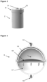
- Figures 1 to 3 show components of an apparatus 1 for dispensing and enriching liquid, namely a liquid tank 2 ( Figures 1 and 2 ) and a gas reservoir 3 ( Figure 3 ).
- the apparatus 1 further comprises a gas supply port 4 which is releasably connectable with a gas tank 5, like a CO 2 bottle, and an inline mixer unit 6 located downstream of the liquid tank 2 and the gas supply port 4.
- Gas enriched liquid may be dispensed from a dispensing tap 7 located downstream of the inline mixer unit 6.
- the components of the apparatus 1 may be fully or partially received in a housing (not shown).
- the liquid tank 2 is a substantially cylindrical container with a removable lid 8 attached to the liquid tank 2 e.g. by bayonet coupling means.
- An, e.g. centrally arranged, tank gas inlet 9 and an , e.g. laterally arranged, tank gas outlet 10 are provided in the lid 8.
- the cylindrical container of the liquid tank 2 has an annular sealing surface 11 facing upwards in Figure 1
- the lid 8 comprises an annular sealing counter-surface 12 arranged to abut the sealing surface 11 when the lid 8 is firmly attached to the cylindrical container of the liquid tank 2.
- the tank gas outlet 10 is arranged opening into the annular sealing counter-surface 12 facing towards the sealing surface 11.
- the tank gas outlet 10 is closed by abutment with the sealing surface 11 when the lid 8 is firmly attached to the cylindrical container of the liquid tank 2.
- the tank gas outlet 10 is opened when the lid 8 is slightly lifted from the sealing surface 11 of the cylindrical container of the liquid tank 2.
- the liquid tank 2 has at its lower end a tank liquid outlet 13.
- An optional filter 14, e.g. a disk-shaped replaceable filter cartridge, may be located in the tank liquid outlet 13.
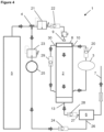
- the gas reservoir 3 may have a substantially spherical outer configuration with a reservoir gas inlet 15 and a reservoir gas outlet 16.
- a reservoir space 17 is defined in communication with the reservoir gas inlet 15 and the reservoir gas outlet 16.
- the gas reservoir 3 further comprises an elastically deformable membrane 18 which is sealed to a shell 19 thereby defining an internal compartment within the reservoir 3.
- the internal compartment is sealed from the reservoir space 17 but may receive pressurized gas by deformation of the membrane 18.
- the membrane 18 and the shell 19 are held withing the gas reservoir 3 by a ring with support ribs such that gas may flow around the internal may be connected to the compartment between reservoir gas inlet 15 and reservoir gas outlet 16.
- the reservoir gas inlet 15 may be connected to the tank gas outlet 10 via a line comprising a check valve 20.
- the gas supply port 4 is connected to the gas tank 5 as well as to the liquid tank 2 and to the inline mixer unit 6.
- At least one first pressure regulator 21 and a check valve 22 are arranged downstream of the gas supply port 4 in a gas line connectable with the tank gas inlet 9.
- at least one second pressure regulator 23, a check valve 24 and a control valve 25 are arranged downstream of the gas supply port 4 in a gas line connectable with a mixer gas inlet 26 of the mixer unit 6.
- the first pressure regulator 21 is set to a higher pressure, e.g. above 4.5 bar, than the pressure of the second pressure regulator 23, e.g. 4.0 bar.
- the mixer unit 6 further comprises a mixer liquid inlet 27 connectable with the tank liquid outlet 13 or the filter 14 via a liquid line which may comprise a further check valve 28.
- the liquid tank 2 is held, e.g. locked, in the apparatus 1 and the lid 8 is firmly attached to the cylindrical container of the liquid tank 2 such that the tank gas outlet 10 is closed.
- the pressurized gas fed from the gas tank 5 via the gas supply port 4 to the liquid tank 2 feeds liquid from the liquid tank 2 to the mixer unit 6.
- pressurized gas is fed from the gas tank 5 via the gas supply port 4 to the inline mixer unit 6 such that liquid from the liquid tank 2 and pressurized gas are mixed, i.e. the liquid is enriched with gas.
- the liquid enriched with gas may be continuously dispensed from the tap 7 until the liquid tank 2 and/or the gas tank 5 run empty.
- the line connecting the gas supply port 4 with the tank gas inlet 9 is disconnected or blocked and the liquid tank 2 is unlocked from the apparatus 1 or its housing, thereby allowing lifting of lid 8.
- the pressure of the gas may elastically deform the membrane 18 bulging into the internal compartment and the shell 19.
- Check valve 20 prevents that pressurized gas flows back towards the liquid tank 2 if the same is removed for refilling.
- Figure 4 shows a configuration of the apparatus 1 according to a first embodiment of the invention.
- the pressurized gas stored in the gas reservoir 3 may be fed into the liquid tank 2 via a line optionally comprising a check valve 29.
- the gas may be introduced via the tank gas inlet 9 or via an additional gas inlet 30 which may open automatically by the pressure exerted when closing the lid 8 firmly onto the container of the liquid tank 2.
- pressurized gas contained in the liquid tank 2 may be re-used for feeding liquid from a refilled liquid tank 2.
- Figure 5 shows a configuration of the apparatus 1 according to a second embodiment of the invention.
- This second embodiment has substantially the same configuration and operation as the above described first embodiment.
- the reservoir gas outlet 16 is not connected to the tank gas inlet 9 or to an additional tank gas inlet 30, but instead connected to the inline mixer unit 6 via the mixer gas inlet 26 or an additional mixer gas inlet 31.
- At least one further check valve 32 and/or a switch 33 may be provided in the line between the reservoir gas outlet 16 and the inline mixer unit 6.
- the first pressure regulator 21 is set to a higher pressure than the pressure of the second pressure regulator 23
- the gas fed from the gas reservoir 3 to the mixer unit 6 has a higher pressure than the gas directly fed from the gas supply port 4. This results in an increased gas enrichment of the liquid.
- pressurized gas contained in the liquid tank 2 may be re-used for enriching liquid with gas.
- the liquid is water and the gas is CO 2 .
- An advantage common to both embodiments is that carbonated water may be continuously produced and dispensed from the apparatus 1 without using electrical energy or without having to connect the device to a water line.
- the comparatively expensive gas used for carbonation and for feeding the water is used very sparingly, as the gas available in an empty liquid tank 2 is reused.
Landscapes
- Chemical & Material Sciences (AREA)
- Chemical Kinetics & Catalysis (AREA)
- Accessories For Mixers (AREA)
Abstract
Description
- The present invention refers to an apparatus for enriching a liquid with gas, e.g. for carbonation of a liquid, for example an apparatus for in-line carbonation of water. Further, the present invention refers to a method for dispensing gas enriched liquid.
- Many different systems and apparatuses for enriching gas in beverage liquids such as water are known on the market. The gas which is used to enrich the respective liquids is typically carbon dioxide (CO2) which is introduced into a beverage container, usually a bottle, via a spout or opening of the container.
- An example of such an apparatus is known from
EP 0 000 813 B1 in which water may be carbonated in a water-filled pressure vessel into which pressurized CO2 is introduced. Gas enriched water may be dispensed from the pressure vessel by introducing further (not gas enriched) water into the pressure vessel with a higher pressure than the gas enriched water in the pressure vessel, e.g. due to gravitational force. Further,DE 10 2015 213 843 A1 andUS 5,124,088 A both disclose devices for carbonation of water in which pressurized CO2 is introduced into a water-filled tank. Gas enriched water may be dispensed from this tank by means of the pressure applied by the CO2 introduced into the tank. These known devices have in common that the amount of gas enriched water which may be dispensed is limited to the volume of the vessel or tank in which the water is carbonated by introducing pressurized CO2. - In addition,
EP 3 107 645 B1 - The need to provide a power supply or a piped water supply is perceived as disadvantageous for some applications.
- Thus, it is an object of the present invention to provide a simple and reliable apparatus and method for carbonation of large quantities of liquid avoiding the drawbacks of known devices.
- This object is solved by an apparatus according to
claim 1 and by a method according toclaim 14. - The present invention is based on the idea of using gas enriched liquid in an inline mixer to which gas and liquid are fed, while the pressure of the gas used for enriching (e.g. carbonation) is further used for feeding the liquid from a tank to the inline mixer unit. This allows operation of the apparatus without requiring electronic components and without an electronic power source. In addition, the apparatus has the benefit of being able to dispense a large amount of gas enriched liquid while being operable without connection to a water line. This makes it possible to provide the apparatus as a mobile or portable device. Still further, the relatively simple mechanical operation of the apparatus results in a high reliability.
- For example, the apparatus for enriching a liquid with gas may substantially comprise a refillable liquid tank, a gas supply port and a mixer unit. The liquid tank may have a liquid outlet and may be releasably locked in the apparatus allowing replacement or refilling of the liquid tank. The mixer unit may have a liquid inlet connectable with the liquid outlet, a mixer gas inlet connectable with a gas supply port and an gas enriched liquid outlet, e.g. with a tap, for dispensing gas enriched liquid. In other words, the mixer unit may be an inline mixer for continuously mixing liquid and gas as they flow through the mixer unit. Further, the liquid tank may comprise a tank gas inlet connectable to the gas supply port. The gas supply port is connectable to a gas tank, e.g. a CO2 bottle.
- In an embodiment, the liquid inlet of the mixer unit is connected with the liquid outlet of the liquid tank via a line which may comprise a check valve and/or blocking means. Further, the mixer gas inlet may be connected with the gas supply port via a line which may comprise a pressure regulator, a control valve, a check valve and/or blocking means. Still further, the tank gas inlet may be connected with the gas supply port via a line which may comprise a pressure regulator, a control valve, a check valve and/or blocking means. The connections to the liquid tank may be made releasable permitting easy detachment of the liquid tank for refilling. In a similar manner, the gas supply port may permit easy attachment and detachment of a gas tank, like a gas bottle.
- According to a further independent aspect of the present invention, the apparatus further comprises a gas reservoir connectable to a tank gas outlet of the liquid tank. The gas reservoir is a container suitable for temporarily storing pressurized gas. For example, the gas reservoir may comprise a reservoir gas inlet, a reservoir gas outlet and a reservoir space in communication with the reservoir gas inlet and the reservoir gas outlet. The reservoir space may serve to receive pressurized gas fed from the liquid tank to the gas reservoir in order to store the pressurized gas and to permit further use of the pressurized gas at a later point in time, e.g. during a subsequent operation. Optionally, the gas reservoir may further comprise an internal compartment sealed from the reservoir space by an elastically deformable membrane. This may contribute in storing more pressurized gas in the gas reservoir.
- The provision of the gas reservoir is based on the idea that feeding liquid from the liquid tank to the mixer unit by means of pressurized gas, results in the liquid tank being substantially filled with the pressurized gas as the liquid tank gets empty. Generally, the pressurized gas may be simply dispensed into the ambient air when refilling the liquid tank. However, as replacement of an empty gas bottle costs time and money, it is preferred to save at least a portion of the pressurized gas in the liquid tank by releasing it into the gas reservoir where it is stored and may be further used.
- In more detail, the gas reservoir may be connected to the tank gas outlet via a valve and/or a blocking device to be selectively closed at least during dispensing gas enriched liquid and to be selectively opened at least at the beginning of a refilling step. Such a refilling step may initially comprise unlocking of the liquid tank form the apparatus or its housing, thereby blocking or disconnecting the gas supply port from the tank gas inlet and permitting a fluid communication between the liquid tank and the gas reservoir. In an embodiment, the liquid tank may comprise a lid detachable from the liquid tank for refilling, wherein a fluid connection between the liquid tank and the gas reservoir is blocked when the lid is air-tight sealed to the liquid tank and when the lid is fully removed from the liquid tank, and wherein the fluid connection between the liquid tank and the gas reservoir is established when the lid is partially lifted from the liquid tank.
- Optionally, the liquid tank comprises an annular sealing surface for sealing abutment with an annular counter sealing surface of the lid wherein the tank gas outlet is arranged in the counter sealing surface. Thus, the tank gas outlet is closed by the sealing surface of the liquid tank if the sealing surface of the liquid tank abuts the counter sealing surface of the lid and automatically opens if the counter sealing surface of the lid is lifted from the sealing surface of the liquid tank. In an example, the lid may be attached to the liquid tank by means of a bayonet coupling permitting in one relative position of the lid relative to the liquid tank that the lid is slightly lifted from the liquid tank due to the internal pressure of the gas in the liquid tank, while still retaining the lid on the liquid tank. This may occur automatically when unlocking the liquid tank from the apparatus prior to exchanging or refilling the liquid tank.
- A first option for using the pressurized gas retained in the gas reservoir, is to reintroduce the gas into the liquid tank after the liquid tank has been refilled. This avoids that excessive amounts of additional pressurized gas have to be used to build up feeding pressure in the liquid tank after refilling the liquid tank. Thus, the gas reservoir may comprise a reservoir gas outlet connectable to the tank gas inlet and/or to an optional further tank gas inlet. Preferably, the connection between the gas reservoir and the liquid tank is established automatically during or after locking the liquid tank in the apparatus. For example, the tank gas inlet and/or to an optional further tank gas inlet comprises a blocking valve which is opened if the sealing surface of the liquid tank abuts the counter sealing surface of the lid, thereby connecting the gas reservoir with the interior of the liquid tank.
- A second additional or alternative option for using the pressurized gas retained in the gas reservoir, is to feed the gas into the inline mixer unit for enriching the liquid. This may include use of the pressurized gas for the inline gas enriching during dispensing gas enriched liquid and/or the use of the pressurized gas as a gas enriching booster in addition to the pressurized gas fed to the mixer unit from the gas supply port, i.e. for increasing the degree of gas enrichment. In this respect, the gas reservoir may comprises a reservoir gas outlet connectable to the mixer gas inlet and/or to a further mixer gas inlet. In more detail, the mixer gas inlet and/or the further mixer gas inlet may comprise a blocking valve operable by a user operated switch button.
- Dispensing and at the same time gas enriching liquid may be facilitated if a first a pressure regulator is provided between the gas supply port and the tank gas inlet, wherein a second a pressure regulator is provided between the gas supply port and the mixer gas inlet wherein the first pressure regulator is set to a higher pressure than the pressure of the second pressure regulator. For example, the first pressure regulator may be set to about 4.5 bar while the second pressure regulator may be set to about 4.0 bar. The difference between the pressure to which the pressure regulators are set may be above 0.1 bar, e.g. at least 0.2 bar, preferably between 0.3 bar and 2.5 bar. The pressure to which the first pressure regulator is set may be above 1.5 bar, e.g. at least 2.0 bar, preferably between 3.0 bar and 7.0 bar.
- The apparatus may further comprise a filter provided in the liquid outlet or interposed between the liquid outlet and the mixer liquid inlet. Preferably, the filter is a replaceable filter cartridge for cleaning the liquid fed from the liquid tank to the inline mixer unit.
- Still further, the apparatus may comprise a housing encasing, at least partially, the refillable liquid tank, the gas supply port, the mixer unit and/or the gas reservoir. The housing may comprise latching means for releasably locking the liquid tank and/or a gas tank into the housing. A tap for dispensing gas enriched liquid from the gas enriched liquid outlet and, optionally, a user operable switch button may be accessible from outside the housing to allow operation of the apparatus. For example, a user may dispense gas enriched liquid from the apparatus simply by opening the tap such that gas enriched liquid is dispensed until either the liquid tank or the gas tank runs empty. As the apparatus is operable without external liquid supply or electricity, use of the apparatus is simple and reliable. An optional booster switch button may be used to increase the degree of gas enrichment by feeding additional pressurized gas and/or gas with higher pressure into the inline mixer unit.
- According to a further aspect of the present invention, a method for producing and dispensing gas enriched liquid comprises the steps of: providing liquid in a refillable liquid tank, providing gas in a gas tank, introducing gas from the gas tank into the liquid tank, thereby dispensing liquid from the liquid tank to an inline mixer unit provided downstream of the liquid tank, introducing gas from the gas tank into the mixer unit, thereby enriching the liquid with gas, and dispensing gas enriched liquid, e.g. by operating a dispensing tap. Preferably, the method further comprises the steps of: releasing gas from the liquid tank into a gas reservoir prior to refilling the liquid tank, and furthermore at least one of the following features i) and ii):
- i) releasing gas from the gas reservoir into the liquid tank after refilling the liquid tank; and/or
- ii) releasing gas from the gas reservoir into the mixer unit during gas enrichment of the liquid.
- For example, the step i) of releasing gas from the liquid tank into a gas reservoir prior to refilling the liquid tank may take place as a lid of the liquid tank is lifted from the liquid tank, thereby establishing a fluid connection between the liquid tank and the gas reservoir.
- While the present invention is generally described with respect to gas enrichment of a liquid, in a preferred embodiment the liquid is water and the gas is CO2, i.e. the apparatus and method are suitable for dispensing and carbonation of water.
- Non-limiting, exemplary embodiments of the invention will now be described with reference to the accompanying drawings, in which:
- Figure 1
- shows in a cross-sectional view a liquid tank of an apparatus according to the present invention;
- Figure 2
- shows in a side view the liquid tank of
Figure 1 ; - Figure 3
- shows in a cross-sectional view a gas reservoir of an apparatus according to the present invention;
- Figure 4
- shows a flowchart of a first embodiment of an apparatus according to the present invention; and
- Figure 5
- shows a flowchart of a second embodiment of an apparatus according to the present invention.
-
Figures 1 to 3 show components of anapparatus 1 for dispensing and enriching liquid, namely a liquid tank 2 (Figures 1 and2 ) and a gas reservoir 3 (Figure 3 ). As shown inFigures 4 and5 , theapparatus 1 further comprises agas supply port 4 which is releasably connectable with a gas tank 5, like a CO2 bottle, and aninline mixer unit 6 located downstream of theliquid tank 2 and thegas supply port 4. Gas enriched liquid may be dispensed from a dispensingtap 7 located downstream of theinline mixer unit 6. The components of theapparatus 1 may be fully or partially received in a housing (not shown). - In the depicted embodiment, the
liquid tank 2 is a substantially cylindrical container with aremovable lid 8 attached to theliquid tank 2 e.g. by bayonet coupling means. An, e.g. centrally arranged,tank gas inlet 9 and an , e.g. laterally arranged,tank gas outlet 10 are provided in thelid 8. The cylindrical container of theliquid tank 2 has anannular sealing surface 11 facing upwards inFigure 1 , whereas thelid 8 comprises anannular sealing counter-surface 12 arranged to abut the sealingsurface 11 when thelid 8 is firmly attached to the cylindrical container of theliquid tank 2. Thetank gas outlet 10 is arranged opening into the annular sealingcounter-surface 12 facing towards the sealingsurface 11. Thus, thetank gas outlet 10 is closed by abutment with the sealingsurface 11 when thelid 8 is firmly attached to the cylindrical container of theliquid tank 2. On the other hand, thetank gas outlet 10 is opened when thelid 8 is slightly lifted from the sealingsurface 11 of the cylindrical container of theliquid tank 2. Still further, theliquid tank 2 has at its lower end atank liquid outlet 13. Anoptional filter 14, e.g. a disk-shaped replaceable filter cartridge, may be located in thetank liquid outlet 13. - The
gas reservoir 3 may have a substantially spherical outer configuration with areservoir gas inlet 15 and areservoir gas outlet 16. In thegas reservoir 3, areservoir space 17 is defined in communication with thereservoir gas inlet 15 and thereservoir gas outlet 16. Thegas reservoir 3 further comprises an elasticallydeformable membrane 18 which is sealed to ashell 19 thereby defining an internal compartment within thereservoir 3. The internal compartment is sealed from thereservoir space 17 but may receive pressurized gas by deformation of themembrane 18. In the embodiment depicted inFigure 3 , themembrane 18 and theshell 19 are held withing thegas reservoir 3 by a ring with support ribs such that gas may flow around the internal may be connected to the compartment betweenreservoir gas inlet 15 andreservoir gas outlet 16. Thereservoir gas inlet 15 may be connected to thetank gas outlet 10 via a line comprising acheck valve 20. - The
gas supply port 4 is connected to the gas tank 5 as well as to theliquid tank 2 and to theinline mixer unit 6. At least onefirst pressure regulator 21 and acheck valve 22 are arranged downstream of thegas supply port 4 in a gas line connectable with thetank gas inlet 9. Further, at least onesecond pressure regulator 23, acheck valve 24 and acontrol valve 25 are arranged downstream of thegas supply port 4 in a gas line connectable with amixer gas inlet 26 of themixer unit 6. Thefirst pressure regulator 21 is set to a higher pressure, e.g. above 4.5 bar, than the pressure of thesecond pressure regulator 23, e.g. 4.0 bar. - The
mixer unit 6 further comprises amixer liquid inlet 27 connectable with thetank liquid outlet 13 or thefilter 14 via a liquid line which may comprise afurther check valve 28. - During regular operation of the
apparatus 1, theliquid tank 2 is held, e.g. locked, in theapparatus 1 and thelid 8 is firmly attached to the cylindrical container of theliquid tank 2 such that thetank gas outlet 10 is closed. With this configuration, the pressurized gas fed from the gas tank 5 via thegas supply port 4 to theliquid tank 2 feeds liquid from theliquid tank 2 to themixer unit 6. Simultaneously, pressurized gas is fed from the gas tank 5 via thegas supply port 4 to theinline mixer unit 6 such that liquid from theliquid tank 2 and pressurized gas are mixed, i.e. the liquid is enriched with gas. The liquid enriched with gas may be continuously dispensed from thetap 7 until theliquid tank 2 and/or the gas tank 5 run empty. - For replacement or refilling of an
empty liquid tank 2, the line connecting thegas supply port 4 with thetank gas inlet 9 is disconnected or blocked and theliquid tank 2 is unlocked from theapparatus 1 or its housing, thereby allowing lifting oflid 8. This opens thetank gas outlet 10 such that pressurized gas is released into thereservoir space 17 of thegas reservoir 3. The pressure of the gas may elastically deform themembrane 18 bulging into the internal compartment and theshell 19. Checkvalve 20 prevents that pressurized gas flows back towards theliquid tank 2 if the same is removed for refilling. -
Figure 4 shows a configuration of theapparatus 1 according to a first embodiment of the invention. After re-introducing a fresh liquid filledliquid tank 2 into the apparatus, the pressurized gas stored in thegas reservoir 3 may be fed into theliquid tank 2 via a line optionally comprising acheck valve 29. The gas may be introduced via thetank gas inlet 9 or via anadditional gas inlet 30 which may open automatically by the pressure exerted when closing thelid 8 firmly onto the container of theliquid tank 2. Thus, pressurized gas contained in theliquid tank 2 may be re-used for feeding liquid from a refilledliquid tank 2. -
Figure 5 shows a configuration of theapparatus 1 according to a second embodiment of the invention. This second embodiment has substantially the same configuration and operation as the above described first embodiment. However, thereservoir gas outlet 16 is not connected to thetank gas inlet 9 or to an additionaltank gas inlet 30, but instead connected to theinline mixer unit 6 via themixer gas inlet 26 or an additional mixer gas inlet 31. At least onefurther check valve 32 and/or aswitch 33 may be provided in the line between thereservoir gas outlet 16 and theinline mixer unit 6. As thefirst pressure regulator 21 is set to a higher pressure than the pressure of thesecond pressure regulator 23, the gas fed from thegas reservoir 3 to themixer unit 6 has a higher pressure than the gas directly fed from thegas supply port 4. This results in an increased gas enrichment of the liquid. Thus, pressurized gas contained in theliquid tank 2 may be re-used for enriching liquid with gas. - In a preferred embodiment, the liquid is water and the gas is CO2.
- An advantage common to both embodiments is that carbonated water may be continuously produced and dispensed from the
apparatus 1 without using electrical energy or without having to connect the device to a water line. In addition, the comparatively expensive gas used for carbonation and for feeding the water is used very sparingly, as the gas available in anempty liquid tank 2 is reused.Reference signs 1 apparatus 18 membrane 2 liquid tank 19 shell 3 gas reservoir 20 check valve 4 gas supply port 21 first pressure regulator 5 gas tank/ gas bottle 22 check valve 6 inline mixer unit 23 second pressure regulator 7 tap/ gas enriched liquid outlet 24 check valve 8 lid 25 control valve 9 tank gas inlet 26 mixer gas inlet 10 tank gas outlet 27 mixer liquid inlet 11 sealing surface 28 check valve 12 sealing counter-surface 29 ckeck valve 13 tank liquid outlet 30 additional tank gas inlet 14 filter 31 additional mixer gas inlet 15 reservoir gas inlet 32 ckeck valve 16 reservoir gas outlet 33 switch 17 reservoir space
Claims (15)
- Apparatus for gas enrichment of a liquid, the apparatus comprising:- a refillable liquid tank (2) having a tank liquid outlet (13),- a gas supply port (4), and- an inline mixer unit (6) having a liquid inlet (27) connectable with the tank liquid outlet (13), a mixer gas inlet (26) connectable with a gas supply port (4) and an gas enriched liquid outlet (7) for dispensing gas enriched liquid,characterized in that
the liquid tank (2) further comprises a tank gas inlet (9) connectable to the gas supply port (4). - Apparatus according to claim 1, further comprising a gas reservoir (3) connectable to a tank gas outlet (10) of the liquid tank (2).
- Apparatus according to claim 2, wherein the gas reservoir (3) is connected to the tank gas outlet (10) via a valve (20) and/or a blocking device (11) to be selectively closed at least during dispensing gas enriched liquid and to be selectively opened at least at the beginning of a liquid tank refilling step.
- Apparatus according to claim 3, wherein the liquid tank (2) comprises a lid (8) detachable from the liquid tank (2) for refilling, wherein a fluid connection between the liquid tank (2) and the gas reservoir (3) is blocked when the lid (8) is air-tight sealed to the liquid tank (2), and wherein the fluid connection between the liquid tank (2) and the gas reservoir (3) is established when the lid (8) is partially lifted from the liquid tank (2).
- Apparatus according to claim 4, wherein the liquid tank (2) comprises an annular sealing surface (11) for sealing abutment with an annular counter sealing surface (12) of the lid (8), and wherein the tank gas outlet (10) is arranged in the counter sealing surface (12) such that the tank gas outlet (10) is closed by the sealing surface (11) of the liquid tank (2) if the sealing surface (11) of the liquid tank (2) abuts the counter sealing surface (12) of the lid (8).
- Apparatus according to any one of claims 2 to 5, wherein the gas reservoir (3) comprises a reservoir gas outlet (16) connectable to the tank gas inlet (9) and/or to an optional further tank gas inlet (30).
- Apparatus according to claim 6, wherein the tank gas inlet (9) and/or to an optional further tank gas inlet (30) comprises a blocking valve which is opened if the sealing surface (11) of the liquid tank (2) abuts the counter sealing surface (12) of the lid (8).
- Apparatus according to any one of claims 2 to 5, wherein the gas reservoir (3) comprises a reservoir gas outlet (16) connectable to the mixer gas inlet (26) and/or to a further mixer gas inlet (31).
- Apparatus according to claim 8, wherein the mixer gas inlet (2) and/or the further mixer gas inlet (31) comprises a blocking valve operable by a user operated switch button (33).
- Apparatus according to any one of claims 2 to 9, wherein the gas reservoir (3) comprises a reservoir gas inlet (15), the reservoir gas outlet (16) and a reservoir space (17) in communication with the reservoir gas inlet (15) and the reservoir gas outlet (16), and wherein the gas reservoir (3) further comprises an internal compartment sealed from the reservoir space (17) by an elastically deformable membrane (18).
- Apparatus according to any one of the preceding claims, wherein a first a pressure regulator (21) is provided between the gas supply port (4) and the tank gas inlet (9), wherein a second a pressure regulator (23) is provided between the gas supply port (4) and the mixer gas inlet (26), and wherein the first pressure regulator (21) is set to a higher pressure, e.g. above 4.5 bar, than the pressure of the second pressure regulator (23), e.g. 4.0 bar.
- Apparatus according to any one of the preceding claims, wherein a gas tank (5), e.g. a refillable CO2 bottle, is connectable with the gas supply port (4).
- Apparatus according to any one of the preceding claims, further comprising a filter (14) provided in the liquid outlet (13) or interposed between the liquid outlet (13) and the mixer liquid inlet (27).
- Method for producing and dispensing gas enriched liquid, preferably by means of an apparatus according to any one of the preceding claims, the method comprising the steps of:- providing liquid in a refillable liquid tank (2),- providing gas in a gas tank (5),- introducing gas from the gas tank (5) into the liquid tank (2), thereby dispensing liquid from the liquid tank (2) to a mixer unit (6) provided downstream of the liquid tank (2),- introducing gas from the gas tank (5) into the mixer unit (6), thereby enriching the liquid with gas, and- dispensing gas enriched liquid.
- Method according to claim 14, further comprising the steps of:- releasing gas from the liquid tank (2) into a gas reservoir (3) prior to refilling the liquid tank (2), andat least one of the following features i) and ii):i) releasing gas from the gas reservoir (3) into the liquid tank (2) after refilling the liquid tank; and/orii) releasing gas from the gas reservoir (3) into the mixer unit (6) during enriching the liquid with gas.
Priority Applications (1)
| Application Number | Priority Date | Filing Date | Title |
|---|---|---|---|
| EP22175550.7A EP4282810B1 (en) | 2022-05-25 | 2022-05-25 | Apparatus and method for enriching a liquid with gas |
Applications Claiming Priority (1)
| Application Number | Priority Date | Filing Date | Title |
|---|---|---|---|
| EP22175550.7A EP4282810B1 (en) | 2022-05-25 | 2022-05-25 | Apparatus and method for enriching a liquid with gas |
Publications (2)
| Publication Number | Publication Date |
|---|---|
| EP4282810A1 true EP4282810A1 (en) | 2023-11-29 |
| EP4282810B1 EP4282810B1 (en) | 2025-01-22 |
Family
ID=81850764
Family Applications (1)
| Application Number | Title | Priority Date | Filing Date |
|---|---|---|---|
| EP22175550.7A Active EP4282810B1 (en) | 2022-05-25 | 2022-05-25 | Apparatus and method for enriching a liquid with gas |
Country Status (1)
| Country | Link |
|---|---|
| EP (1) | EP4282810B1 (en) |
Citations (9)
| Publication number | Priority date | Publication date | Assignee | Title |
|---|---|---|---|---|
| US572779A (en) * | 1896-12-08 | theurer | ||
| US3756576A (en) * | 1970-02-26 | 1973-09-04 | F Tremolada | Apparatus for charging a liquid with gas |
| EP0000813B1 (en) | 1977-07-29 | 1980-12-10 | Sodastream Limited | Portable apparatus for carbonating water |
| US5124088A (en) | 1990-09-04 | 1992-06-23 | Stumphauzer William C | Process and apparatus for rapidly carbonating water |
| US6059270A (en) * | 1997-11-06 | 2000-05-09 | Kkb 02 Fluid Production Gmbh | Liquid enriched with a gas, a method of enriching a liquid with a gas, and an apparatus for enriching a liquid with a gas |
| WO2015175244A2 (en) * | 2014-05-15 | 2015-11-19 | Ac Beverage, Inc. | Chilled n2 infused beverage dispensing system and method to prepare and dispense a chilled n2 infused beverage |
| DE102015213843A1 (en) | 2015-07-22 | 2017-01-26 | Wmf Group Gmbh | Device for introducing gases into liquids |
| EP3107645B1 (en) | 2014-02-19 | 2020-10-28 | Luxembourg Patent Company S.A. | In-line carbonation of water-base beverages |
| US20210283558A1 (en) * | 2016-08-05 | 2021-09-16 | Cornelius, Inc. | Apparatuses for Mixing Gases into Liquids |
-
2022
- 2022-05-25 EP EP22175550.7A patent/EP4282810B1/en active Active
Patent Citations (9)
| Publication number | Priority date | Publication date | Assignee | Title |
|---|---|---|---|---|
| US572779A (en) * | 1896-12-08 | theurer | ||
| US3756576A (en) * | 1970-02-26 | 1973-09-04 | F Tremolada | Apparatus for charging a liquid with gas |
| EP0000813B1 (en) | 1977-07-29 | 1980-12-10 | Sodastream Limited | Portable apparatus for carbonating water |
| US5124088A (en) | 1990-09-04 | 1992-06-23 | Stumphauzer William C | Process and apparatus for rapidly carbonating water |
| US6059270A (en) * | 1997-11-06 | 2000-05-09 | Kkb 02 Fluid Production Gmbh | Liquid enriched with a gas, a method of enriching a liquid with a gas, and an apparatus for enriching a liquid with a gas |
| EP3107645B1 (en) | 2014-02-19 | 2020-10-28 | Luxembourg Patent Company S.A. | In-line carbonation of water-base beverages |
| WO2015175244A2 (en) * | 2014-05-15 | 2015-11-19 | Ac Beverage, Inc. | Chilled n2 infused beverage dispensing system and method to prepare and dispense a chilled n2 infused beverage |
| DE102015213843A1 (en) | 2015-07-22 | 2017-01-26 | Wmf Group Gmbh | Device for introducing gases into liquids |
| US20210283558A1 (en) * | 2016-08-05 | 2021-09-16 | Cornelius, Inc. | Apparatuses for Mixing Gases into Liquids |
Also Published As
| Publication number | Publication date |
|---|---|
| EP4282810B1 (en) | 2025-01-22 |
Similar Documents
| Publication | Publication Date | Title |
|---|---|---|
| US8191867B2 (en) | Method and apparatus for carbonizing a liquid | |
| JP5425075B2 (en) | Module for modular beverage dispensing system | |
| RU2629868C2 (en) | Dosing device for beverages with carbonation system | |
| US6619318B2 (en) | Multiple flow rate eductive dispenser | |
| AU610026B2 (en) | Gas generator for a carbonated drink dispenser | |
| US4785974A (en) | System for serving a pre-mix beverage or making and serving a post-mix beverage in the zero gravity conditions of outer space | |
| US6719175B2 (en) | Draft system for beverages | |
| CN109562333B (en) | Device for mixing a gas into a liquid | |
| US5957339A (en) | Water filtration system | |
| US4709734A (en) | Method and system for filling packages with a carbonated beverage pre-mix under micro-gravity conditions | |
| US10477883B2 (en) | Gas injection assemblies for batch beverages having spargers | |
| US20230406611A1 (en) | Bottle | |
| KR20230092864A (en) | portable fizzy dispenser | |
| AU677830B2 (en) | Method of and an apparatus for using an ink concentrate in an ink jet printing arrangement | |
| EP4282810B1 (en) | Apparatus and method for enriching a liquid with gas | |
| GB1589413A (en) | Delivery of a liquid alone or admixed with a second liquid | |
| US3370753A (en) | Plural source fluid dispenser | |
| US20080248164A1 (en) | Supply Component for Liquids and Gases | |
| EP1698391B1 (en) | Refrigerated core comprising carbonating system for drinks dispenser | |
| CN111954470A (en) | Gas Entrainment Systems for Beverages | |
| US20240239643A1 (en) | Pressure vessel for gas and beverage dispenser with pressure vessel | |
| CN117098482B (en) | A top-mounted liquid-replenishing foam generating device | |
| HK40086537A (en) | Portable carbonating dispensers | |
| WO1991019276A1 (en) | Automatic control system for accurately dispensing mixed drinks | |
| MXPA97004622A (en) | Portable dosing for bebi |
Legal Events
| Date | Code | Title | Description |
|---|---|---|---|
| PUAI | Public reference made under article 153(3) epc to a published international application that has entered the european phase |
Free format text: ORIGINAL CODE: 0009012 |
|
| STAA | Information on the status of an ep patent application or granted ep patent |
Free format text: STATUS: THE APPLICATION HAS BEEN PUBLISHED |
|
| AK | Designated contracting states |
Kind code of ref document: A1 Designated state(s): AL AT BE BG CH CY CZ DE DK EE ES FI FR GB GR HR HU IE IS IT LI LT LU LV MC MK MT NL NO PL PT RO RS SE SI SK SM TR |
|
| STAA | Information on the status of an ep patent application or granted ep patent |
Free format text: STATUS: REQUEST FOR EXAMINATION WAS MADE |
|
| 17P | Request for examination filed |
Effective date: 20240527 |
|
| RBV | Designated contracting states (corrected) |
Designated state(s): AL AT BE BG CH CY CZ DE DK EE ES FI FR GB GR HR HU IE IS IT LI LT LU LV MC MK MT NL NO PL PT RO RS SE SI SK SM TR |
|
| GRAP | Despatch of communication of intention to grant a patent |
Free format text: ORIGINAL CODE: EPIDOSNIGR1 |
|
| STAA | Information on the status of an ep patent application or granted ep patent |
Free format text: STATUS: GRANT OF PATENT IS INTENDED |
|
| RIC1 | Information provided on ipc code assigned before grant |
Ipc: B01F 23/236 20220101ALI20240828BHEP Ipc: B01F 35/71 20220101ALI20240828BHEP Ipc: B67D 1/04 20060101ALI20240828BHEP Ipc: B67D 1/00 20060101AFI20240828BHEP |
|
| INTG | Intention to grant announced |
Effective date: 20240910 |
|
| GRAS | Grant fee paid |
Free format text: ORIGINAL CODE: EPIDOSNIGR3 |
|
| GRAA | (expected) grant |
Free format text: ORIGINAL CODE: 0009210 |
|
| STAA | Information on the status of an ep patent application or granted ep patent |
Free format text: STATUS: THE PATENT HAS BEEN GRANTED |
|
| AK | Designated contracting states |
Kind code of ref document: B1 Designated state(s): AL AT BE BG CH CY CZ DE DK EE ES FI FR GB GR HR HU IE IS IT LI LT LU LV MC MK MT NL NO PL PT RO RS SE SI SK SM TR |
|
| REG | Reference to a national code |
Ref country code: GB Ref legal event code: FG4D |
|
| REG | Reference to a national code |
Ref country code: CH Ref legal event code: EP |
|
| REG | Reference to a national code |
Ref country code: IE Ref legal event code: FG4D |
|
| REG | Reference to a national code |
Ref country code: DE Ref legal event code: R096 Ref document number: 602022009725 Country of ref document: DE |
|
| P01 | Opt-out of the competence of the unified patent court (upc) registered |
Free format text: CASE NUMBER: APP_6599/2025 Effective date: 20250207 |
|
| REG | Reference to a national code |
Ref country code: NL Ref legal event code: MP Effective date: 20250122 |
|
| PG25 | Lapsed in a contracting state [announced via postgrant information from national office to epo] |
Ref country code: NL Free format text: LAPSE BECAUSE OF FAILURE TO SUBMIT A TRANSLATION OF THE DESCRIPTION OR TO PAY THE FEE WITHIN THE PRESCRIBED TIME-LIMIT Effective date: 20250122 |
|
| PG25 | Lapsed in a contracting state [announced via postgrant information from national office to epo] |
Ref country code: RS Free format text: LAPSE BECAUSE OF FAILURE TO SUBMIT A TRANSLATION OF THE DESCRIPTION OR TO PAY THE FEE WITHIN THE PRESCRIBED TIME-LIMIT Effective date: 20250422 |
|
| PG25 | Lapsed in a contracting state [announced via postgrant information from national office to epo] |
Ref country code: FI Free format text: LAPSE BECAUSE OF FAILURE TO SUBMIT A TRANSLATION OF THE DESCRIPTION OR TO PAY THE FEE WITHIN THE PRESCRIBED TIME-LIMIT Effective date: 20250122 |
|
| PG25 | Lapsed in a contracting state [announced via postgrant information from national office to epo] |
Ref country code: PL Free format text: LAPSE BECAUSE OF FAILURE TO SUBMIT A TRANSLATION OF THE DESCRIPTION OR TO PAY THE FEE WITHIN THE PRESCRIBED TIME-LIMIT Effective date: 20250122 |
|
| PGFP | Annual fee paid to national office [announced via postgrant information from national office to epo] |
Ref country code: DE Payment date: 20250402 Year of fee payment: 4 |
|
| PG25 | Lapsed in a contracting state [announced via postgrant information from national office to epo] |
Ref country code: ES Free format text: LAPSE BECAUSE OF FAILURE TO SUBMIT A TRANSLATION OF THE DESCRIPTION OR TO PAY THE FEE WITHIN THE PRESCRIBED TIME-LIMIT Effective date: 20250122 |
|
| REG | Reference to a national code |
Ref country code: LT Ref legal event code: MG9D |
|
| PG25 | Lapsed in a contracting state [announced via postgrant information from national office to epo] |
Ref country code: IS Free format text: LAPSE BECAUSE OF FAILURE TO SUBMIT A TRANSLATION OF THE DESCRIPTION OR TO PAY THE FEE WITHIN THE PRESCRIBED TIME-LIMIT Effective date: 20250522 Ref country code: NO Free format text: LAPSE BECAUSE OF FAILURE TO SUBMIT A TRANSLATION OF THE DESCRIPTION OR TO PAY THE FEE WITHIN THE PRESCRIBED TIME-LIMIT Effective date: 20250422 |
|
| REG | Reference to a national code |
Ref country code: AT Ref legal event code: MK05 Ref document number: 1761361 Country of ref document: AT Kind code of ref document: T Effective date: 20250122 |
|
| PG25 | Lapsed in a contracting state [announced via postgrant information from national office to epo] |
Ref country code: HR Free format text: LAPSE BECAUSE OF FAILURE TO SUBMIT A TRANSLATION OF THE DESCRIPTION OR TO PAY THE FEE WITHIN THE PRESCRIBED TIME-LIMIT Effective date: 20250122 |
|
| PG25 | Lapsed in a contracting state [announced via postgrant information from national office to epo] |
Ref country code: LV Free format text: LAPSE BECAUSE OF FAILURE TO SUBMIT A TRANSLATION OF THE DESCRIPTION OR TO PAY THE FEE WITHIN THE PRESCRIBED TIME-LIMIT Effective date: 20250122 Ref country code: PT Free format text: LAPSE BECAUSE OF FAILURE TO SUBMIT A TRANSLATION OF THE DESCRIPTION OR TO PAY THE FEE WITHIN THE PRESCRIBED TIME-LIMIT Effective date: 20250522 |
|
| PGFP | Annual fee paid to national office [announced via postgrant information from national office to epo] |
Ref country code: FR Payment date: 20250401 Year of fee payment: 4 |
|
| PG25 | Lapsed in a contracting state [announced via postgrant information from national office to epo] |
Ref country code: GR Free format text: LAPSE BECAUSE OF FAILURE TO SUBMIT A TRANSLATION OF THE DESCRIPTION OR TO PAY THE FEE WITHIN THE PRESCRIBED TIME-LIMIT Effective date: 20250423 Ref country code: BG Free format text: LAPSE BECAUSE OF FAILURE TO SUBMIT A TRANSLATION OF THE DESCRIPTION OR TO PAY THE FEE WITHIN THE PRESCRIBED TIME-LIMIT Effective date: 20250122 |
|
| PG25 | Lapsed in a contracting state [announced via postgrant information from national office to epo] |
Ref country code: AT Free format text: LAPSE BECAUSE OF FAILURE TO SUBMIT A TRANSLATION OF THE DESCRIPTION OR TO PAY THE FEE WITHIN THE PRESCRIBED TIME-LIMIT Effective date: 20250122 |
|
| PG25 | Lapsed in a contracting state [announced via postgrant information from national office to epo] |
Ref country code: SE Free format text: LAPSE BECAUSE OF FAILURE TO SUBMIT A TRANSLATION OF THE DESCRIPTION OR TO PAY THE FEE WITHIN THE PRESCRIBED TIME-LIMIT Effective date: 20250122 |
|
| PG25 | Lapsed in a contracting state [announced via postgrant information from national office to epo] |
Ref country code: SM Free format text: LAPSE BECAUSE OF FAILURE TO SUBMIT A TRANSLATION OF THE DESCRIPTION OR TO PAY THE FEE WITHIN THE PRESCRIBED TIME-LIMIT Effective date: 20250122 |
|
| PG25 | Lapsed in a contracting state [announced via postgrant information from national office to epo] |
Ref country code: DK Free format text: LAPSE BECAUSE OF FAILURE TO SUBMIT A TRANSLATION OF THE DESCRIPTION OR TO PAY THE FEE WITHIN THE PRESCRIBED TIME-LIMIT Effective date: 20250122 |
|
| PG25 | Lapsed in a contracting state [announced via postgrant information from national office to epo] |
Ref country code: IT Free format text: LAPSE BECAUSE OF FAILURE TO SUBMIT A TRANSLATION OF THE DESCRIPTION OR TO PAY THE FEE WITHIN THE PRESCRIBED TIME-LIMIT Effective date: 20250122 |
|
| PG25 | Lapsed in a contracting state [announced via postgrant information from national office to epo] |
Ref country code: EE Free format text: LAPSE BECAUSE OF FAILURE TO SUBMIT A TRANSLATION OF THE DESCRIPTION OR TO PAY THE FEE WITHIN THE PRESCRIBED TIME-LIMIT Effective date: 20250122 Ref country code: CZ Free format text: LAPSE BECAUSE OF FAILURE TO SUBMIT A TRANSLATION OF THE DESCRIPTION OR TO PAY THE FEE WITHIN THE PRESCRIBED TIME-LIMIT Effective date: 20250122 |
|
| REG | Reference to a national code |
Ref country code: DE Ref legal event code: R097 Ref document number: 602022009725 Country of ref document: DE |
|
| PG25 | Lapsed in a contracting state [announced via postgrant information from national office to epo] |
Ref country code: RO Free format text: LAPSE BECAUSE OF FAILURE TO SUBMIT A TRANSLATION OF THE DESCRIPTION OR TO PAY THE FEE WITHIN THE PRESCRIBED TIME-LIMIT Effective date: 20250122 |
|
| PG25 | Lapsed in a contracting state [announced via postgrant information from national office to epo] |
Ref country code: SK Free format text: LAPSE BECAUSE OF FAILURE TO SUBMIT A TRANSLATION OF THE DESCRIPTION OR TO PAY THE FEE WITHIN THE PRESCRIBED TIME-LIMIT Effective date: 20250122 |
|
| PLBE | No opposition filed within time limit |
Free format text: ORIGINAL CODE: 0009261 |
|
| STAA | Information on the status of an ep patent application or granted ep patent |
Free format text: STATUS: NO OPPOSITION FILED WITHIN TIME LIMIT |
|
| REG | Reference to a national code |
Ref country code: CH Ref legal event code: L10 Free format text: ST27 STATUS EVENT CODE: U-0-0-L10-L00 (AS PROVIDED BY THE NATIONAL OFFICE) Effective date: 20251203 |
|
| REG | Reference to a national code |
Ref country code: CH Ref legal event code: H13 Free format text: ST27 STATUS EVENT CODE: U-0-0-H10-H13 (AS PROVIDED BY THE NATIONAL OFFICE) Effective date: 20251223 |
|
| 26N | No opposition filed |
Effective date: 20251023 |
|
| PG25 | Lapsed in a contracting state [announced via postgrant information from national office to epo] |
Ref country code: LU Free format text: LAPSE BECAUSE OF NON-PAYMENT OF DUE FEES Effective date: 20250525 |
|
| PG25 | Lapsed in a contracting state [announced via postgrant information from national office to epo] |
Ref country code: CH Free format text: LAPSE BECAUSE OF NON-PAYMENT OF DUE FEES Effective date: 20250531 |
|
| REG | Reference to a national code |
Ref country code: BE Ref legal event code: MM Effective date: 20250531 |
|
| PG25 | Lapsed in a contracting state [announced via postgrant information from national office to epo] |
Ref country code: MC Free format text: LAPSE BECAUSE OF FAILURE TO SUBMIT A TRANSLATION OF THE DESCRIPTION OR TO PAY THE FEE WITHIN THE PRESCRIBED TIME-LIMIT Effective date: 20250122 |
|
| PG25 | Lapsed in a contracting state [announced via postgrant information from national office to epo] |
Ref country code: IE Free format text: LAPSE BECAUSE OF NON-PAYMENT OF DUE FEES Effective date: 20250525 |
|
| PG25 | Lapsed in a contracting state [announced via postgrant information from national office to epo] |
Ref country code: BE Free format text: LAPSE BECAUSE OF NON-PAYMENT OF DUE FEES Effective date: 20250531 |