EP4282730A1 - Railroad car air conditioner - Google Patents
Railroad car air conditioner Download PDFInfo
- Publication number
- EP4282730A1 EP4282730A1 EP21863053.1A EP21863053A EP4282730A1 EP 4282730 A1 EP4282730 A1 EP 4282730A1 EP 21863053 A EP21863053 A EP 21863053A EP 4282730 A1 EP4282730 A1 EP 4282730A1
- Authority
- EP
- European Patent Office
- Prior art keywords
- ultraviolet
- conditioning system
- heat exchanger
- air conditioning
- air
- Prior art date
- Legal status (The legal status is an assumption and is not a legal conclusion. Google has not performed a legal analysis and makes no representation as to the accuracy of the status listed.)
- Granted
Links
Images


Classifications
-
- B—PERFORMING OPERATIONS; TRANSPORTING
- B61—RAILWAYS
- B61D—BODY DETAILS OR KINDS OF RAILWAY VEHICLES
- B61D27/00—Heating, cooling, ventilating, or air-conditioning
- B61D27/0018—Air-conditioning means, i.e. combining at least two of the following ways of treating or supplying air, namely heating, cooling or ventilating
-
- B—PERFORMING OPERATIONS; TRANSPORTING
- B60—VEHICLES IN GENERAL
- B60H—ARRANGEMENTS OF HEATING, COOLING, VENTILATING OR OTHER AIR-TREATING DEVICES SPECIALLY ADAPTED FOR PASSENGER OR GOODS SPACES OF VEHICLES
- B60H3/00—Other air-treating devices
- B60H3/0071—Electrically conditioning the air, e.g. by ionizing
-
- B—PERFORMING OPERATIONS; TRANSPORTING
- B61—RAILWAYS
- B61D—BODY DETAILS OR KINDS OF RAILWAY VEHICLES
- B61D27/00—Heating, cooling, ventilating, or air-conditioning
-
- B—PERFORMING OPERATIONS; TRANSPORTING
- B60—VEHICLES IN GENERAL
- B60Y—INDEXING SCHEME RELATING TO ASPECTS CROSS-CUTTING VEHICLE TECHNOLOGY
- B60Y2200/00—Type of vehicle
- B60Y2200/30—Railway vehicles
-
- Y—GENERAL TAGGING OF NEW TECHNOLOGICAL DEVELOPMENTS; GENERAL TAGGING OF CROSS-SECTIONAL TECHNOLOGIES SPANNING OVER SEVERAL SECTIONS OF THE IPC; TECHNICAL SUBJECTS COVERED BY FORMER USPC CROSS-REFERENCE ART COLLECTIONS [XRACs] AND DIGESTS
- Y02—TECHNOLOGIES OR APPLICATIONS FOR MITIGATION OR ADAPTATION AGAINST CLIMATE CHANGE
- Y02T—CLIMATE CHANGE MITIGATION TECHNOLOGIES RELATED TO TRANSPORTATION
- Y02T30/00—Transportation of goods or passengers via railways, e.g. energy recovery or reducing air resistance
Definitions
- the present invention relates to an air conditioning system for a railway vehicle.
- Patent Document 1 an air conditioning system for a railway vehicle which is disclosed in Patent Document 1 is available, for example.
- a technology of sterilizing bacteria floating in the air by using a photocatalyst is disclosed.
- the technology does not necessarily demonstrate a sufficient effect for disinfection of the inside of the air conditioning system to which bacteria, viruses, and so forth have already adhered.
- Patent Document 1 JP-1999-192942-A
- an air conditioning system for a railway vehicle that is of a roof installation type, the air conditioning system including a heat exchanger through which at least air inside the railway vehicle passes and an ultraviolet-ray irradiation device, the heat exchanger and the ultraviolet-ray irradiation device being arranged between an upper cover curved in an upwardly protruding shape and a bottom plate.
- the heat exchanger has an air suction surface arranged so as to be irradiated with ultraviolet rays generated by the ultraviolet-ray irradiation device.
- a member that does not transmit the ultraviolet rays is arranged on a straight line interconnecting the ultraviolet-ray irradiation device and an interior space of the railway vehicle.
- an air conditioning system for a railway vehicle that allows a surface of a heat exchanger in the air conditioning system to which not only dust but also bacteria, viruses, and so forth are likely to adhere, to be kept hygienic by employing a safe method and that is thus superior in hygiene.
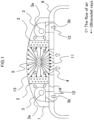
- FIG. 1 is a cross sectional view depicting an internal configuration of an air conditioning system 1 for a railway vehicle (hereinafter, also simply referred to as an "air conditioning system") according to the first embodiment of the present invention.
- FIG. 1 is a cross sectional view of a principal part of the air conditioning system 1 which is taken along a plane perpendicular to a longitudinal direction of the body of the vehicle
- FIG. 2 is a view depicting a component 7 of a fin tube heat exchanger (hereinafter, also simply referred to as a "heat exchanger”) 2 which is used in the air conditioning system 1 for a railway vehicle depicted in FIG. 1 .
- the air conditioning system 1 is mounted on a roof of a vehicle body 6.
- the air conditioning system 1 includes principal equipment accommodated in a space surrounded by an upper cover 13 and a substantially flat plate-shaped bottom plate 14 of the air conditioning system 1.
- a pair of heat exchangers 2 each having an outer profile of a thick plate are arranged in parallel to each other at a predetermined interval such that they are facing each other, and an ultraviolet-ray irradiation device 5 is disposed in the center between the heat exchangers 2.
- the ultraviolet-ray irradiation device 5 is disposed on the windward side of the heat exchangers 2 so as to face the heat exchangers 2.
- each of the heat exchangers 2 is of the type called a fin tube type.
- the component 7 of the heat exchanger 2 has such a structure that heat transfer tubes 9 having a hairpin shape extend through a number of flat plate-shaped fins 8. Adjacent ones of the heat transfer tubes 9 are connected to each other at end portions thereof by a joint such as a return pipe 10 to form a refrigerant (heat medium) flow path.
- the heat exchangers 2 in the first embodiment are disposed such that a longitudinal direction of the heat transfer tubes 9 coincides with the longitudinal direction of the vehicle body. It is to be noted that, since the heat exchanger 2 has such a structure as to send the air in a direction perpendicular to the heat transfer tubes 9, the heat exchanger 2 sends the air in a direction perpendicular to the longitudinal direction of the vehicle body. Further, a centrifugal fan is used in the air blower 3. Generally, a centrifugal fan or a sirocco fan is configured to suck the air in a direction of an axis of rotation thereof and blow out the air in a direction perpendicular to the axis of the rotation. Since a ventilation path in the inside of the air blower 3 is bent at a substantially right angle, the light passing property from a suction port to a blowout port is extremely low.
- the air blower 3 in the first embodiment depicted in FIG. 1 is configured such that the suction port thereof is open in an air suction direction which is coincident with the longitudinal direction of the vehicle body.
- the degree of ultraviolet rays that enter the suction port from a direction perpendicular to the suction direction is extremely low.
- the suction grill 4 has a plurality of blades of a substantially flat plate shape. The blades are arrayed such that longitudinal directions thereof are substantially the same as one another. Further, the angle and the length of the blades in the flow direction are set such that surfaces of the blades intersect with a straight line interconnecting the ultraviolet irradiation device and the inside of the vehicle. Moreover, a fluorescent substance is applied to the surfaces of the blades.
- Suction surfaces of the heat exchangers 2 to which not only dust but also bacteria, viruses, and so forth are likely to adhere are irradiated with ultraviolet rays which are emitted from the ultraviolet-ray irradiation device 5, bringing about an effect of embrittling the dust and of disinfecting the bacteria, viruses, and so forth.
- the upper cover 1 and the suction grill 4 of the air conditioning system 1 are irradiated with ultraviolet rays which are emitted from the ultraviolet-ray irradiation device 5 in directions other than the directions toward the heat exchangers 2.
- the suction grill 4 has the blades whose angle and length in the flow direction are arranged such that the surfaces of the blades intersect with the straight line interconnecting the ultraviolet irradiation device and the inside of the vehicle, as described hereinabove. Therefore, the ultraviolet rays emitted from the ultraviolet-ray irradiation device 5 are suppressed from leaking directly into the vehicle and thus do not adversely affect passengers in the vehicle.
- the ultraviolet rays emitted to the surfaces of the blades cause the fluorescent substance applied to the surfaces of the blades to emit light.
- a person in the vehicle who sees the emitted light can confirm that the ultraviolet irradiation device is operating.
- Such a function that allows operation confirmation through the light emission as described above brings about an effect of making passengers feel safe and making cleanliness of the inside of the vehicle appeal to the passengers.
- the heat exchanger 2 is of the fin tube type including a number of fins 8 on a flat plate and has a high light passing property in a direction in which the air permeability is preferable.
- the air suction direction of the air blowers 3 located on the downwind side of the heat exchangers 2 is the longitudinal direction of the vehicle, even if ultraviolet rays leak through the gaps between the fins 8 in a direction perpendicular to the longitudinal direction of the vehicle, that is, in a ventilation direction, the ultraviolet rays are prevented from passing through the air blowers 3 and leaking into the vehicle.
- the air conditioning system 1 can demonstrate an effect of embrittling dust and disinfecting bacteria, viruses, and so forth, by emitting ultraviolet rays to the surfaces of the heat exchangers 2 with certainty, and can also prevent leakage of the ultraviolet rays into the vehicle.
- the air conditioning system for a railway vehicle that allows the surfaces of the heat exchangers 2 in the air conditioning system to be kept hygienic by employing a safe method and that is thus superior in hygiene.
- FIG. 3 is a cross sectional view depicting an internal configuration of an air conditioning system 1A for a railway vehicle according to the second embodiment of the present invention and, in particular, is a cross sectional view of a principal part of the air conditioning system 1 which is taken along a plane perpendicular to the longitudinal direction of the body of the vehicle.
- the air conditioning system 1 is mounted on the roof of the vehicle body 6 as depicted in FIG. 2 .
- the air conditioning system 1 includes principal equipment accommodated in a space surrounded by the upper cover 13 and the substantially flat plate-shaped bottom plate 14 of the air conditioning system 1.
- the ultraviolet-ray irradiation device 5 is disposed above the air blower 3 so as to face the heat exchangers 2 and the upper cover 13.
- an ultraviolet lamp of the straight tube type is used in the ultraviolet-ray irradiation device 5.
- an ultraviolet-ray source of the LED type may alternatively be used, for example.
- the second embodiment is similar to the first embodiment in that the heat exchangers 2 are of the fin tube type and the air blower 3 includes a centrifugal fan or a sirocco fan.
- a portion of an inner surface of the upper cover of the air conditioning system is processed so as to reflect ultraviolet rays and forms a reflection surface 13a of the inner surface of the upper cover.
- the reflection surface 13a of the inner surface of the upper cover is formed by attaching, to the inner surface of the upper cover, a sheet which reflects ultraviolet rays.
- the suction surfaces of the heat exchangers 2 to which not only dust but also bacteria, viruses, and so forth are likely to adhere are directly irradiated with ultraviolet rays emitted from the ultraviolet-ray irradiation device 5 and are also indirectly irradiated with ultraviolet rays reflected by the reflection surface 13a of the inner surface of the upper cover.
- the suction surfaces of the heat exchangers 2 can be irradiated more effectively than the case where they are irradiated with only direct light.
- the air conditioning system 1A of the second embodiment even if the number of the ultraviolet-ray irradiation devices 5 or the irradiation intensity thereof is reduced, a disinfection effect which is equivalent to that with the air conditioning system 1 of the first embodiment can be produced. Further, although ultraviolet rays emitted downwardly from the ultraviolet-ray irradiation device 5 partly enter the air blower 3 through the blowout port 3b thereof, the ultraviolet rays do not leak into the vehicle since the suction direction and blowout direction of the air blower 3 are perpendicular to each other.
- the air conditioning system 1A can demonstrate an effect of embrittling dust and disinfecting bacteria, viruses, and so forth, and can also prevent leakage of the ultraviolet rays into the vehicle.
- the air conditioning system 1A for a railway vehicle that allows the surfaces of the heat exchangers 2 in the air conditioning system to be kept hygienic by employing a safe method and that is thus superior in hygiene.
- the air conditioning system 1 for a railway vehicle (hereinafter referred to as the "present system 1") according to the embodiment of the present invention can be summarized as follows.
- Each of the first and second surfaces that form the principal surfaces is herein referred to as a "surface" in order to specify any portion of the heat exchanger 2 on the basis of an appearance, and even if it macroscopically is a "surface,” it microscopically has a form of a lattice in which a large number of gaps are lined up. Since the first surface and the second surface have a low air resistance in a direction perpendicular thereto and a favorable air passing property, the first surface of such a latticed pattern as described above forms an air suction surface, and the second surface similar to the first surface forms an air delivery surface.
- the air suction surface of the heat exchanger 2 is arranged so as to be irradiated with ultraviolet rays generated by the ultraviolet-ray irradiation device 5. Therefore, the ultraviolet rays enter a deep portion of the air suction surface, which is open in the latticed pattern and has the gaps formed therein, to a certain extent along surfaces of a number of fins 8 arranged perpendicularly to the air suction surface. Accordingly, by the ultraviolet rays emitted from the ultraviolet-ray irradiation device, dust adhering to the surface of the heat exchanger 2 and the surfaces of the fins 8 in the air conditioning system is embrittled, and an effect of disinfecting bacteria, viruses, and so forth is demonstrated.
- a member that does not transmit the ultraviolet rays is arranged on a straight line interconnecting the ultraviolet-ray irradiation device 5 and an interior space of the vehicle. Accordingly, the safety is ensured for passengers who are in the interior space of the vehicle in which irradiation of the ultraviolet rays by the ultraviolet-ray irradiation device 5 is shielded.
- the present system 1 allows the surface of the heat exchanger 2 in the air conditioning system, to which not only dust but also bacteria, viruses, and so forth are like to adhere, to be kept hygienic by employing a safe method and is thus superior in hygiene.
- a grill 4 is arranged at a suction port 11 that sucks the air inside the railway vehicle, the grill 4 having a plurality of blades arrayed in substantially the same direction.
- the size and angle of each of the blades of the grill 4 are set such that a surface of the blade intersects with a straight line interconnecting the ultraviolet-ray irradiation device 5 and the suction port, to thereby reduce the light passing property in a direction of the straight line. Accordingly, the ultraviolet rays can be prevented from leaking directly into the vehicle and from adversely affecting the passengers in the vehicle.
- the heat exchanger 2 is of a fin tube type, and an air blower 3 of a sirocco type or a centrifugal type is disposed on a downwind side of the heat exchanger 2.
- the centrifugal fan or the sirocco fan has an axis of rotation coincident with the longitudinal direction of the vehicle body, that is, with the advancing direction of the vehicle body, and the air is sucked in a direction of the axis of the rotation while the air is blown out in a direction perpendicular to the direction of the axis of the rotation.
- the suction direction is substantially the same as a tube axis direction of the heat transfer tube 9 of the heat exchanger 2. Specifically, since the suction direction and the blowout direction of the air blower 3 are perpendicular to each other, although ultraviolet rays emitted downwardly from the ultraviolet-ray irradiation device 5 partly enter the air blower 3 through the blowout port 3b thereof, the ultraviolet rays cannot advance straight in the bent internal ventilation path. Consequently, the ultraviolet rays do not leak into the vehicle.
- a fluorescent material is applied to a surface (blade surface) of the blade of the grill 4. Since the ultraviolet rays emitted to the blade surface causes the fluorescent material applied to the blade surface to emit light, it is possible to confirm operation of the ultraviolet-ray irradiation device from the inside of the vehicle. Consequently, an effect of making passengers feel safe and making cleanliness of the inside of the vehicle appeal to the passengers is produced.
- an inner surface of the upper cover 13 has at least a portion that faces a windward side of the heat exchanger 2 and that reflects the ultraviolet rays.
- the suction surface of the heat exchanger 2 is directly irradiated with ultraviolet rays emitted from the ultraviolet-ray irradiation device 5 and is also indirectly irradiated with ultraviolet rays reflected by the reflection surface 13a of the inner surface of the upper cover.
- the suction surface of the heat exchanger 2 can be irradiated more effectively than the case where it is irradiated with only direct light. Therefore, the number of the ultraviolet-ray irradiation devices 5 or the irradiation intensity thereof can be reduced and saved to achieve an equivalent disinfection effect.
Landscapes
- Engineering & Computer Science (AREA)
- Mechanical Engineering (AREA)
- Air Filters, Heat-Exchange Apparatuses, And Housings Of Air-Conditioning Units (AREA)
- Air-Conditioning For Vehicles (AREA)
Abstract
Description
- The present invention relates to an air conditioning system for a railway vehicle.
- Although most of the bacteria and viruses as well as dust floating in air inside a railway vehicle are forcibly discharged to the outside of the vehicle by ventilation equipment and are also naturally discharged from openings at doors and so forth, some of them adhere to wall surfaces, floor surfaces, and the inside of the air conditioning system. Among them, the wall surfaces and the floor surfaces are kept hygienic by periodical disinfection works.
- However, a cleaning work and a disinfection work for the inside of the air conditioning system are performed only in a case in which maintenance of the air conditioning system is performed. In recent years, with the growing interest in new infectious diseases and so forth that occur frequently, especially a railway vehicle that serves as public transportation means is required to further reduce bacteria, viruses, and so forth remaining in the vehicle than before.
- To meet such a request from the society as described, an air conditioning system for a railway vehicle which is disclosed in Patent Document 1 is available, for example. In the example in Patent Document 1, a technology of sterilizing bacteria floating in the air by using a photocatalyst is disclosed. However, the technology does not necessarily demonstrate a sufficient effect for disinfection of the inside of the air conditioning system to which bacteria, viruses, and so forth have already adhered.
- Patent Document 1:
JP-1999-192942-A - It is an object of the present invention to provide an air conditioning system for a railway vehicle that allows a surface of a heat exchanger in the air conditioning system to which not only dust but also bacteria, viruses, and so forth are likely to adhere, to be kept hygienic by employing a safe method and that is thus superior in hygiene.
- In order to achieve the object, according to the present invention, there is provided an air conditioning system for a railway vehicle that is of a roof installation type, the air conditioning system including a heat exchanger through which at least air inside the railway vehicle passes and an ultraviolet-ray irradiation device, the heat exchanger and the ultraviolet-ray irradiation device being arranged between an upper cover curved in an upwardly protruding shape and a bottom plate. The heat exchanger has an air suction surface arranged so as to be irradiated with ultraviolet rays generated by the ultraviolet-ray irradiation device. A member that does not transmit the ultraviolet rays is arranged on a straight line interconnecting the ultraviolet-ray irradiation device and an interior space of the railway vehicle.
- According to the present invention, it is possible to provide an air conditioning system for a railway vehicle that allows a surface of a heat exchanger in the air conditioning system to which not only dust but also bacteria, viruses, and so forth are likely to adhere, to be kept hygienic by employing a safe method and that is thus superior in hygiene.
-
-
FIG. 1 is a cross sectional view depicting an internal configuration of an air conditioning system for a railway vehicle according to a first embodiment of the present invention. -
FIG. 2 is a view depicting a component of a fin tube heat exchanger which is used in the air conditioning system for a railway vehicle depicted inFIG. 1 . -
FIG. 3 is a cross sectional view depicting an internal configuration of an air conditioning system for a railway vehicle according to a second embodiment of the present invention. - In the following, embodiments of the present invention are described with reference to the accompanying drawings.
- A first embodiment of the present invention is described with reference to
FIGS. 1 and2 .FIG. 1 is a cross sectional view depicting an internal configuration of an air conditioning system 1 for a railway vehicle (hereinafter, also simply referred to as an "air conditioning system") according to the first embodiment of the present invention. In particular,FIG. 1 is a cross sectional view of a principal part of the air conditioning system 1 which is taken along a plane perpendicular to a longitudinal direction of the body of the vehicle, whileFIG. 2 is a view depicting acomponent 7 of a fin tube heat exchanger (hereinafter, also simply referred to as a "heat exchanger") 2 which is used in the air conditioning system 1 for a railway vehicle depicted inFIG. 1 . As depicted inFIG. 1 , the air conditioning system 1 is mounted on a roof of avehicle body 6. The air conditioning system 1 includes principal equipment accommodated in a space surrounded by anupper cover 13 and a substantially flat plate-shaped bottom plate 14 of the air conditioning system 1. - A pair of
heat exchangers 2 each having an outer profile of a thick plate are arranged in parallel to each other at a predetermined interval such that they are facing each other, and an ultraviolet-ray irradiation device 5 is disposed in the center between theheat exchangers 2. The ultraviolet-ray irradiation device 5 is disposed on the windward side of theheat exchangers 2 so as to face theheat exchangers 2. When the air conditioning system 1 operates, airflow is generated byair blowers 3, and air flowing in the vehicle is then introduced into the air conditioning system 1 through anair suction port 11 in which asuction grill 4 is disposed. Then, the air is cooled or heated by theheat exchangers 2 and returns to the inside of the vehicle fromair blowout ports 12 through theair blowers 3. - In the first embodiment, an ultraviolet lamp of the straight tube type is used in the ultraviolet-
ray irradiation device 5. However, an ultraviolet-ray source of the LED type may alternatively be used, for example. As depicted inFIG. 2 , each of theheat exchangers 2 is of the type called a fin tube type. Thecomponent 7 of theheat exchanger 2 has such a structure thatheat transfer tubes 9 having a hairpin shape extend through a number of flat plate-shaped fins 8. Adjacent ones of theheat transfer tubes 9 are connected to each other at end portions thereof by a joint such as areturn pipe 10 to form a refrigerant (heat medium) flow path. - The
heat exchangers 2 in the first embodiment are disposed such that a longitudinal direction of theheat transfer tubes 9 coincides with the longitudinal direction of the vehicle body. It is to be noted that, since theheat exchanger 2 has such a structure as to send the air in a direction perpendicular to theheat transfer tubes 9, theheat exchanger 2 sends the air in a direction perpendicular to the longitudinal direction of the vehicle body. Further, a centrifugal fan is used in theair blower 3. Generally, a centrifugal fan or a sirocco fan is configured to suck the air in a direction of an axis of rotation thereof and blow out the air in a direction perpendicular to the axis of the rotation. Since a ventilation path in the inside of theair blower 3 is bent at a substantially right angle, the light passing property from a suction port to a blowout port is extremely low. - Besides, the
air blower 3 in the first embodiment depicted inFIG. 1 is configured such that the suction port thereof is open in an air suction direction which is coincident with the longitudinal direction of the vehicle body. The degree of ultraviolet rays that enter the suction port from a direction perpendicular to the suction direction is extremely low. Thesuction grill 4 has a plurality of blades of a substantially flat plate shape. The blades are arrayed such that longitudinal directions thereof are substantially the same as one another. Further, the angle and the length of the blades in the flow direction are set such that surfaces of the blades intersect with a straight line interconnecting the ultraviolet irradiation device and the inside of the vehicle. Moreover, a fluorescent substance is applied to the surfaces of the blades. - Suction surfaces of the
heat exchangers 2 to which not only dust but also bacteria, viruses, and so forth are likely to adhere are irradiated with ultraviolet rays which are emitted from the ultraviolet-ray irradiation device 5, bringing about an effect of embrittling the dust and of disinfecting the bacteria, viruses, and so forth. The upper cover 1 and thesuction grill 4 of the air conditioning system 1 are irradiated with ultraviolet rays which are emitted from the ultraviolet-ray irradiation device 5 in directions other than the directions toward theheat exchangers 2. - It is commonly known that the ultraviolet rays have not only a beneficial bactericidal action but also an adverse effect on the human body, especially, on the eyes and the skin. In this regard, the
suction grill 4 has the blades whose angle and length in the flow direction are arranged such that the surfaces of the blades intersect with the straight line interconnecting the ultraviolet irradiation device and the inside of the vehicle, as described hereinabove. Therefore, the ultraviolet rays emitted from the ultraviolet-ray irradiation device 5 are suppressed from leaking directly into the vehicle and thus do not adversely affect passengers in the vehicle. - Further, the ultraviolet rays emitted to the surfaces of the blades cause the fluorescent substance applied to the surfaces of the blades to emit light. A person in the vehicle who sees the emitted light can confirm that the ultraviolet irradiation device is operating. Such a function that allows operation confirmation through the light emission as described above brings about an effect of making passengers feel safe and making cleanliness of the inside of the vehicle appeal to the passengers. As described hereinabove, the
heat exchanger 2 is of the fin tube type including a number offins 8 on a flat plate and has a high light passing property in a direction in which the air permeability is preferable. - In a case where ultraviolet rays are emitted to the suction surfaces of the
heat exchangers 2 having such a structure as described above, there is a possibility that some of the ultraviolet rays may leak to the downwind side of theheat exchangers 2 through gaps between the fins. However, in the first embodiment, since the air suction direction of theair blowers 3 located on the downwind side of theheat exchangers 2 is the longitudinal direction of the vehicle, even if ultraviolet rays leak through the gaps between thefins 8 in a direction perpendicular to the longitudinal direction of the vehicle, that is, in a ventilation direction, the ultraviolet rays are prevented from passing through theair blowers 3 and leaking into the vehicle. - In this manner, according to the present configuration, the air conditioning system 1 can demonstrate an effect of embrittling dust and disinfecting bacteria, viruses, and so forth, by emitting ultraviolet rays to the surfaces of the
heat exchangers 2 with certainty, and can also prevent leakage of the ultraviolet rays into the vehicle. In other words, it is possible to provide the air conditioning system for a railway vehicle that allows the surfaces of theheat exchangers 2 in the air conditioning system to be kept hygienic by employing a safe method and that is thus superior in hygiene. - Now, a second embodiment of the present invention is described with reference to
FIG. 3. FIG. 3 is a cross sectional view depicting an internal configuration of anair conditioning system 1A for a railway vehicle according to the second embodiment of the present invention and, in particular, is a cross sectional view of a principal part of the air conditioning system 1 which is taken along a plane perpendicular to the longitudinal direction of the body of the vehicle. The air conditioning system 1 is mounted on the roof of thevehicle body 6 as depicted inFIG. 2 . The air conditioning system 1 includes principal equipment accommodated in a space surrounded by theupper cover 13 and the substantially flat plate-shaped bottom plate 14 of the air conditioning system 1. - When the
air conditioning system 1A operates, airflow is generated by theair blower 3, and air flowing in the vehicle is then introduced into the air conditioning system 1 through theair suction port 11. Then, the air passes through theair blower 3, is cooled or heated by theheat exchangers 2, and then return to the inside of the vehicle from theair blowout ports 12. The ultraviolet-ray irradiation device 5 is disposed above theair blower 3 so as to face theheat exchangers 2 and theupper cover 13. - In the
air conditioning system 1A of the second embodiment, an ultraviolet lamp of the straight tube type is used in the ultraviolet-ray irradiation device 5. However, an ultraviolet-ray source of the LED type may alternatively be used, for example. It is to be noted that the second embodiment is similar to the first embodiment in that theheat exchangers 2 are of the fin tube type and theair blower 3 includes a centrifugal fan or a sirocco fan. - It is to be noted that a portion of an inner surface of the upper cover of the air conditioning system is processed so as to reflect ultraviolet rays and forms a
reflection surface 13a of the inner surface of the upper cover. Specifically, thereflection surface 13a of the inner surface of the upper cover is formed by attaching, to the inner surface of the upper cover, a sheet which reflects ultraviolet rays. - The suction surfaces of the
heat exchangers 2 to which not only dust but also bacteria, viruses, and so forth are likely to adhere are directly irradiated with ultraviolet rays emitted from the ultraviolet-ray irradiation device 5 and are also indirectly irradiated with ultraviolet rays reflected by thereflection surface 13a of the inner surface of the upper cover. In other words, the suction surfaces of theheat exchangers 2 can be irradiated more effectively than the case where they are irradiated with only direct light. - Consequently, according to the
air conditioning system 1A of the second embodiment, even if the number of the ultraviolet-ray irradiation devices 5 or the irradiation intensity thereof is reduced, a disinfection effect which is equivalent to that with the air conditioning system 1 of the first embodiment can be produced. Further, although ultraviolet rays emitted downwardly from the ultraviolet-ray irradiation device 5 partly enter theair blower 3 through theblowout port 3b thereof, the ultraviolet rays do not leak into the vehicle since the suction direction and blowout direction of theair blower 3 are perpendicular to each other. - In this manner, with the configuration of the
air conditioning system 1A according to the second embodiment, since ultraviolet rays can be emitted to the surfaces of theheat exchangers 2 with a higher degree of certainty, theair conditioning system 1A can demonstrate an effect of embrittling dust and disinfecting bacteria, viruses, and so forth, and can also prevent leakage of the ultraviolet rays into the vehicle. In other words, it is possible to provide theair conditioning system 1A for a railway vehicle that allows the surfaces of theheat exchangers 2 in the air conditioning system to be kept hygienic by employing a safe method and that is thus superior in hygiene. - The air conditioning system 1 for a railway vehicle (hereinafter referred to as the "present system 1") according to the embodiment of the present invention can be summarized as follows.
- [1] The present system 1 is an air conditioning system 1 for a railway vehicle that is of a roof installation type, the air conditioning system 1 including a
heat exchanger 2 through which at least air inside the railway vehicle passes, and an ultraviolet-ray irradiation device 5, theheat exchanger 2 and the ultraviolet-ray irradiation device 5 being arranged between anupper cover 13 curved in an upwardly protruding shape and a bottom plate 14. Theheat exchanger 2 has an appearance of a thick plate or a flattened box, and has a first surface and a second surface which are principal surfaces having the greatest area and which are facing each other. Theheat exchanger 2 performs a heat exchange when the air is sent from the first surface to the second surface, adjusting room temperature. - Each of the first and second surfaces that form the principal surfaces is herein referred to as a "surface" in order to specify any portion of the
heat exchanger 2 on the basis of an appearance, and even if it macroscopically is a "surface," it microscopically has a form of a lattice in which a large number of gaps are lined up. Since the first surface and the second surface have a low air resistance in a direction perpendicular thereto and a favorable air passing property, the first surface of such a latticed pattern as described above forms an air suction surface, and the second surface similar to the first surface forms an air delivery surface. - The air suction surface of the
heat exchanger 2 is arranged so as to be irradiated with ultraviolet rays generated by the ultraviolet-ray irradiation device 5. Therefore, the ultraviolet rays enter a deep portion of the air suction surface, which is open in the latticed pattern and has the gaps formed therein, to a certain extent along surfaces of a number offins 8 arranged perpendicularly to the air suction surface. Accordingly, by the ultraviolet rays emitted from the ultraviolet-ray irradiation device, dust adhering to the surface of theheat exchanger 2 and the surfaces of thefins 8 in the air conditioning system is embrittled, and an effect of disinfecting bacteria, viruses, and so forth is demonstrated. - A member that does not transmit the ultraviolet rays is arranged on a straight line interconnecting the ultraviolet-
ray irradiation device 5 and an interior space of the vehicle. Accordingly, the safety is ensured for passengers who are in the interior space of the vehicle in which irradiation of the ultraviolet rays by the ultraviolet-ray irradiation device 5 is shielded. In other words, the present system 1 allows the surface of theheat exchanger 2 in the air conditioning system, to which not only dust but also bacteria, viruses, and so forth are like to adhere, to be kept hygienic by employing a safe method and is thus superior in hygiene. - [2] In the present system 1 according to [1] above, as the member that does not transmit the ultraviolet rays, a
grill 4 is arranged at asuction port 11 that sucks the air inside the railway vehicle, thegrill 4 having a plurality of blades arrayed in substantially the same direction. The size and angle of each of the blades of thegrill 4 are set such that a surface of the blade intersects with a straight line interconnecting the ultraviolet-ray irradiation device 5 and the suction port, to thereby reduce the light passing property in a direction of the straight line. Accordingly, the ultraviolet rays can be prevented from leaking directly into the vehicle and from adversely affecting the passengers in the vehicle. - [3] In the present system 1 according to [1] above, the
heat exchanger 2 is of a fin tube type, and anair blower 3 of a sirocco type or a centrifugal type is disposed on a downwind side of theheat exchanger 2. The centrifugal fan or the sirocco fan has an axis of rotation coincident with the longitudinal direction of the vehicle body, that is, with the advancing direction of the vehicle body, and the air is sucked in a direction of the axis of the rotation while the air is blown out in a direction perpendicular to the direction of the axis of the rotation. - The suction direction is substantially the same as a tube axis direction of the
heat transfer tube 9 of theheat exchanger 2. Specifically, since the suction direction and the blowout direction of theair blower 3 are perpendicular to each other, although ultraviolet rays emitted downwardly from the ultraviolet-ray irradiation device 5 partly enter theair blower 3 through theblowout port 3b thereof, the ultraviolet rays cannot advance straight in the bent internal ventilation path. Consequently, the ultraviolet rays do not leak into the vehicle. - [4] In the present system 1 according to [1] above, a fluorescent material is applied to a surface (blade surface) of the blade of the
grill 4. Since the ultraviolet rays emitted to the blade surface causes the fluorescent material applied to the blade surface to emit light, it is possible to confirm operation of the ultraviolet-ray irradiation device from the inside of the vehicle. Consequently, an effect of making passengers feel safe and making cleanliness of the inside of the vehicle appeal to the passengers is produced. - [5] In the present system according to [1] above, an inner surface of the
upper cover 13 has at least a portion that faces a windward side of theheat exchanger 2 and that reflects the ultraviolet rays. For example, the suction surface of theheat exchanger 2 is directly irradiated with ultraviolet rays emitted from the ultraviolet-ray irradiation device 5 and is also indirectly irradiated with ultraviolet rays reflected by thereflection surface 13a of the inner surface of the upper cover. As a result, since the suction surface of theheat exchanger 2 can be irradiated more effectively than the case where it is irradiated with only direct light. Therefore, the number of the ultraviolet-ray irradiation devices 5 or the irradiation intensity thereof can be reduced and saved to achieve an equivalent disinfection effect. -
- 1, 1A:
- Air conditioning system for a railway vehicle
- 2:
- Heat exchanger
- 3:
- Air blower
- 4:
- (Suction) grill
- 5:
- Ultraviolet-ray irradiation device
- 6:
- Vehicle body
- 7:
- Component of the
heat exchanger 2 - 8:
- Fin
- 9:
- Transfer tube
- 10:
- Return pipe
- 11:
- Air suction port (in a vehicle)
- 12:
- Air blowout port
- 13:
- Upper cover
- 14:
- Bottom plate
Claims (5)
- An air conditioning system for a railway vehicle that is of a roof installation type, the air conditioning system comprising:a heat exchanger through which at least air inside the railway vehicle passes; andan ultraviolet-ray irradiation device,the heat exchanger and the ultraviolet-ray irradiation device being arranged between an upper cover curved in an upwardly protruding shape and a bottom plate, whereinthe heat exchanger has an air suction surface arranged so as to be irradiated with ultraviolet rays generated by the ultraviolet-ray irradiation device, anda member that does not transmit the ultraviolet rays is arranged on a straight line interconnecting the ultraviolet-ray irradiation device and an interior space of the railway vehicle.
- The air conditioning system for a railway vehicle according to claim 1, wherein,as the member that does not transmit the ultraviolet rays,a grill is arranged at a suction port that sucks the air inside the railway vehicle, the grill having a plurality of blades arrayed in substantially the same direction, anda size and an angle of each of the blades of the grill are set such that a straight line interconnecting the ultraviolet-ray irradiation device and the suction port intersects with a surface of the blade without fail.
- The air conditioning system for a railway vehicle according to claim 1, whereinthe heat exchanger is of a fin tube type, and an air blower of a sirocco type or a centrifugal type is disposed on a downwind side of the heat exchanger, anda suction direction of the air blower is substantially the same as a tube axis direction of the heat exchanger.
- The air conditioning system for a railway vehicle according to claim 2, wherein
a fluorescent material is applied to the surface of the blade of the grill. - The air conditioning system for a railway vehicle according to claim 1, wherein
an inner surface of the upper cover has at least a portion that faces a windward side of the heat exchanger and that reflects the ultraviolet rays.
Applications Claiming Priority (1)
| Application Number | Priority Date | Filing Date | Title |
|---|---|---|---|
| PCT/JP2021/002343 WO2022157951A1 (en) | 2021-01-22 | 2021-01-22 | Railroad car air conditioner |
Publications (3)
| Publication Number | Publication Date |
|---|---|
| EP4282730A1 true EP4282730A1 (en) | 2023-11-29 |
| EP4282730A4 EP4282730A4 (en) | 2024-11-06 |
| EP4282730B1 EP4282730B1 (en) | 2025-08-13 |
Family
ID=82548619
Family Applications (1)
| Application Number | Title | Priority Date | Filing Date |
|---|---|---|---|
| EP21863053.1A Active EP4282730B1 (en) | 2021-01-22 | 2021-01-22 | Railroad car air conditioner |
Country Status (4)
| Country | Link |
|---|---|
| US (1) | US20230150553A1 (en) |
| EP (1) | EP4282730B1 (en) |
| JP (1) | JP7171967B1 (en) |
| WO (1) | WO2022157951A1 (en) |
Family Cites Families (9)
| Publication number | Priority date | Publication date | Assignee | Title |
|---|---|---|---|---|
| US2165830A (en) * | 1937-12-23 | 1939-07-11 | B F Sturtevant Co | Air conditioning system for passenger vehicles |
| US4679616A (en) * | 1983-12-20 | 1987-07-14 | Suetrak U.S.A., Inc. | Roof-mounted air conditioner system having modular evaporator and condensor units |
| JPS61169814U (en) * | 1985-04-12 | 1986-10-21 | ||
| JPH11192942A (en) * | 1998-01-08 | 1999-07-21 | Hitachi Ltd | Railcar air conditioners |
| US8506367B2 (en) * | 2009-07-30 | 2013-08-13 | Thermo King Corporation | Mobile air cleaning unit and distribution system |
| JP5866194B2 (en) * | 2011-12-12 | 2016-02-17 | 川崎重工業株式会社 | Air conditioner and railway vehicle |
| CA2946116A1 (en) * | 2014-04-17 | 2015-10-22 | Clean Air For The People Inc. | Air treatment systems for transportation enclosures and related methods |
| RU2610923C1 (en) * | 2015-10-28 | 2017-02-17 | Николай Джемалович Кикнадзе | Air conditioning system of railroad cars (versions) |
| US11046153B1 (en) * | 2020-06-16 | 2021-06-29 | Knorr Brake Company, LLC | Three stage air purification for rail vehicles |
-
2021
- 2021-01-22 US US17/640,496 patent/US20230150553A1/en not_active Abandoned
- 2021-01-22 JP JP2022505522A patent/JP7171967B1/en active Active
- 2021-01-22 EP EP21863053.1A patent/EP4282730B1/en active Active
- 2021-01-22 WO PCT/JP2021/002343 patent/WO2022157951A1/en not_active Ceased
Also Published As
| Publication number | Publication date |
|---|---|
| WO2022157951A1 (en) | 2022-07-28 |
| EP4282730A4 (en) | 2024-11-06 |
| EP4282730B1 (en) | 2025-08-13 |
| JPWO2022157951A1 (en) | 2022-07-28 |
| JP7171967B1 (en) | 2022-11-15 |
| US20230150553A1 (en) | 2023-05-18 |
Similar Documents
| Publication | Publication Date | Title |
|---|---|---|
| JP5626588B2 (en) | Air conditioning system | |
| CN1281898C (en) | Air conditioner | |
| US12535234B2 (en) | Air sterilization apparatus and air conditioner using same | |
| JP7761988B2 (en) | Sterilizer | |
| JP2018162898A (en) | Air conditioner | |
| US20170299289A1 (en) | Uv decontamination system for climate control systems | |
| JP7795096B2 (en) | air purifier | |
| EP4282730B1 (en) | Railroad car air conditioner | |
| KR101341110B1 (en) | Air conditioner having antifungal and air cleaning heat exchanger improved air flow | |
| JP2020134027A (en) | Indoor unit | |
| JP2020133915A (en) | Drainage unit and indoor unit of air conditioner | |
| KR102537504B1 (en) | Air conditioning equipment for preventing spread of infectious diseases | |
| JP7364800B2 (en) | Air sterilization equipment and air conditioning equipment using it | |
| JPH11192942A (en) | Railcar air conditioners | |
| JP6964301B1 (en) | Hall air conditioning system | |
| JP7284779B2 (en) | air conditioner | |
| JP7685841B2 (en) | Vehicle air conditioning system | |
| KR101720299B1 (en) | Air conditioner with ultra violet light emitting diode | |
| CN211345564U (en) | Air conditioner | |
| JP2021177837A (en) | Air circulator with sterilizer | |
| CN101065634A (en) | Heat exchanger | |
| CN116583650A (en) | Ceiling structure and equipment with air sterilizing device comprising such ceiling structure | |
| CN204128159U (en) | heat exchange unit | |
| WO2023112235A1 (en) | Indoor unit and air conditioner | |
| EP4273462A1 (en) | Air conditioner |
Legal Events
| Date | Code | Title | Description |
|---|---|---|---|
| STAA | Information on the status of an ep patent application or granted ep patent |
Free format text: STATUS: UNKNOWN |
|
| STAA | Information on the status of an ep patent application or granted ep patent |
Free format text: STATUS: THE INTERNATIONAL PUBLICATION HAS BEEN MADE |
|
| PUAI | Public reference made under article 153(3) epc to a published international application that has entered the european phase |
Free format text: ORIGINAL CODE: 0009012 |
|
| STAA | Information on the status of an ep patent application or granted ep patent |
Free format text: STATUS: REQUEST FOR EXAMINATION WAS MADE |
|
| 17P | Request for examination filed |
Effective date: 20220329 |
|
| AK | Designated contracting states |
Kind code of ref document: A1 Designated state(s): AL AT BE BG CH CY CZ DE DK EE ES FI FR GB GR HR HU IE IS IT LI LT LU LV MC MK MT NL NO PL PT RO RS SE SI SK SM TR |
|
| DAV | Request for validation of the european patent (deleted) | ||
| DAX | Request for extension of the european patent (deleted) | ||
| A4 | Supplementary search report drawn up and despatched |
Effective date: 20241004 |
|
| RIC1 | Information provided on ipc code assigned before grant |
Ipc: B61D 27/00 20060101AFI20240927BHEP |
|
| GRAP | Despatch of communication of intention to grant a patent |
Free format text: ORIGINAL CODE: EPIDOSNIGR1 |
|
| STAA | Information on the status of an ep patent application or granted ep patent |
Free format text: STATUS: GRANT OF PATENT IS INTENDED |
|
| INTG | Intention to grant announced |
Effective date: 20250321 |
|
| GRAS | Grant fee paid |
Free format text: ORIGINAL CODE: EPIDOSNIGR3 |
|
| GRAA | (expected) grant |
Free format text: ORIGINAL CODE: 0009210 |
|
| STAA | Information on the status of an ep patent application or granted ep patent |
Free format text: STATUS: THE PATENT HAS BEEN GRANTED |
|
| AK | Designated contracting states |
Kind code of ref document: B1 Designated state(s): AL AT BE BG CH CY CZ DE DK EE ES FI FR GB GR HR HU IE IS IT LI LT LU LV MC MK MT NL NO PL PT RO RS SE SI SK SM TR |
|
| REG | Reference to a national code |
Ref country code: GB Ref legal event code: FG4D |
|
| REG | Reference to a national code |
Ref country code: CH Ref legal event code: EP |
|
| REG | Reference to a national code |
Ref country code: DE Ref legal event code: R096 Ref document number: 602021036353 Country of ref document: DE |
|
| REG | Reference to a national code |
Ref country code: IE Ref legal event code: FG4D |
|
| REG | Reference to a national code |
Ref country code: NL Ref legal event code: MP Effective date: 20250813 |
|
| PG25 | Lapsed in a contracting state [announced via postgrant information from national office to epo] |
Ref country code: IS Free format text: LAPSE BECAUSE OF FAILURE TO SUBMIT A TRANSLATION OF THE DESCRIPTION OR TO PAY THE FEE WITHIN THE PRESCRIBED TIME-LIMIT Effective date: 20251213 |
|
| PG25 | Lapsed in a contracting state [announced via postgrant information from national office to epo] |
Ref country code: NO Free format text: LAPSE BECAUSE OF FAILURE TO SUBMIT A TRANSLATION OF THE DESCRIPTION OR TO PAY THE FEE WITHIN THE PRESCRIBED TIME-LIMIT Effective date: 20251113 |
|
| REG | Reference to a national code |
Ref country code: LT Ref legal event code: MG9D |
|
| PG25 | Lapsed in a contracting state [announced via postgrant information from national office to epo] |
Ref country code: PT Free format text: LAPSE BECAUSE OF FAILURE TO SUBMIT A TRANSLATION OF THE DESCRIPTION OR TO PAY THE FEE WITHIN THE PRESCRIBED TIME-LIMIT Effective date: 20251215 |
|
| PG25 | Lapsed in a contracting state [announced via postgrant information from national office to epo] |
Ref country code: FI Free format text: LAPSE BECAUSE OF FAILURE TO SUBMIT A TRANSLATION OF THE DESCRIPTION OR TO PAY THE FEE WITHIN THE PRESCRIBED TIME-LIMIT Effective date: 20250813 |
|
| PG25 | Lapsed in a contracting state [announced via postgrant information from national office to epo] |
Ref country code: NL Free format text: LAPSE BECAUSE OF FAILURE TO SUBMIT A TRANSLATION OF THE DESCRIPTION OR TO PAY THE FEE WITHIN THE PRESCRIBED TIME-LIMIT Effective date: 20250813 Ref country code: HR Free format text: LAPSE BECAUSE OF FAILURE TO SUBMIT A TRANSLATION OF THE DESCRIPTION OR TO PAY THE FEE WITHIN THE PRESCRIBED TIME-LIMIT Effective date: 20250813 |
|
| PG25 | Lapsed in a contracting state [announced via postgrant information from national office to epo] |
Ref country code: GR Free format text: LAPSE BECAUSE OF FAILURE TO SUBMIT A TRANSLATION OF THE DESCRIPTION OR TO PAY THE FEE WITHIN THE PRESCRIBED TIME-LIMIT Effective date: 20251114 |
|
| PG25 | Lapsed in a contracting state [announced via postgrant information from national office to epo] |
Ref country code: SE Free format text: LAPSE BECAUSE OF FAILURE TO SUBMIT A TRANSLATION OF THE DESCRIPTION OR TO PAY THE FEE WITHIN THE PRESCRIBED TIME-LIMIT Effective date: 20250813 |
|
| PG25 | Lapsed in a contracting state [announced via postgrant information from national office to epo] |
Ref country code: LV Free format text: LAPSE BECAUSE OF FAILURE TO SUBMIT A TRANSLATION OF THE DESCRIPTION OR TO PAY THE FEE WITHIN THE PRESCRIBED TIME-LIMIT Effective date: 20250813 |
|
| PG25 | Lapsed in a contracting state [announced via postgrant information from national office to epo] |
Ref country code: PL Free format text: LAPSE BECAUSE OF FAILURE TO SUBMIT A TRANSLATION OF THE DESCRIPTION OR TO PAY THE FEE WITHIN THE PRESCRIBED TIME-LIMIT Effective date: 20250813 Ref country code: BG Free format text: LAPSE BECAUSE OF FAILURE TO SUBMIT A TRANSLATION OF THE DESCRIPTION OR TO PAY THE FEE WITHIN THE PRESCRIBED TIME-LIMIT Effective date: 20250813 |
|
| PG25 | Lapsed in a contracting state [announced via postgrant information from national office to epo] |
Ref country code: RS Free format text: LAPSE BECAUSE OF FAILURE TO SUBMIT A TRANSLATION OF THE DESCRIPTION OR TO PAY THE FEE WITHIN THE PRESCRIBED TIME-LIMIT Effective date: 20251113 |
|
| PG25 | Lapsed in a contracting state [announced via postgrant information from national office to epo] |
Ref country code: ES Free format text: LAPSE BECAUSE OF FAILURE TO SUBMIT A TRANSLATION OF THE DESCRIPTION OR TO PAY THE FEE WITHIN THE PRESCRIBED TIME-LIMIT Effective date: 20250813 |
|
| REG | Reference to a national code |
Ref country code: AT Ref legal event code: MK05 Ref document number: 1824403 Country of ref document: AT Kind code of ref document: T Effective date: 20250813 |
|
| PG25 | Lapsed in a contracting state [announced via postgrant information from national office to epo] |
Ref country code: SM Free format text: LAPSE BECAUSE OF FAILURE TO SUBMIT A TRANSLATION OF THE DESCRIPTION OR TO PAY THE FEE WITHIN THE PRESCRIBED TIME-LIMIT Effective date: 20250813 |
|
| PGFP | Annual fee paid to national office [announced via postgrant information from national office to epo] |
Ref country code: GB Payment date: 20260122 Year of fee payment: 6 |
|
| PG25 | Lapsed in a contracting state [announced via postgrant information from national office to epo] |
Ref country code: DK Free format text: LAPSE BECAUSE OF FAILURE TO SUBMIT A TRANSLATION OF THE DESCRIPTION OR TO PAY THE FEE WITHIN THE PRESCRIBED TIME-LIMIT Effective date: 20250813 |
|
| PG25 | Lapsed in a contracting state [announced via postgrant information from national office to epo] |
Ref country code: AT Free format text: LAPSE BECAUSE OF FAILURE TO SUBMIT A TRANSLATION OF THE DESCRIPTION OR TO PAY THE FEE WITHIN THE PRESCRIBED TIME-LIMIT Effective date: 20250813 |
|
| PGFP | Annual fee paid to national office [announced via postgrant information from national office to epo] |
Ref country code: IT Payment date: 20260130 Year of fee payment: 6 |
|
| PG25 | Lapsed in a contracting state [announced via postgrant information from national office to epo] |
Ref country code: CZ Free format text: LAPSE BECAUSE OF FAILURE TO SUBMIT A TRANSLATION OF THE DESCRIPTION OR TO PAY THE FEE WITHIN THE PRESCRIBED TIME-LIMIT Effective date: 20250813 |
|
| PG25 | Lapsed in a contracting state [announced via postgrant information from national office to epo] |
Ref country code: EE Free format text: LAPSE BECAUSE OF FAILURE TO SUBMIT A TRANSLATION OF THE DESCRIPTION OR TO PAY THE FEE WITHIN THE PRESCRIBED TIME-LIMIT Effective date: 20250813 Ref country code: SK Free format text: LAPSE BECAUSE OF FAILURE TO SUBMIT A TRANSLATION OF THE DESCRIPTION OR TO PAY THE FEE WITHIN THE PRESCRIBED TIME-LIMIT Effective date: 20250813 |