EP4282726A1 - Air drag model estimation using visual information - Google Patents
Air drag model estimation using visual information Download PDFInfo
- Publication number
- EP4282726A1 EP4282726A1 EP22175819.6A EP22175819A EP4282726A1 EP 4282726 A1 EP4282726 A1 EP 4282726A1 EP 22175819 A EP22175819 A EP 22175819A EP 4282726 A1 EP4282726 A1 EP 4282726A1
- Authority
- EP
- European Patent Office
- Prior art keywords
- vehicle combination
- exterior shape
- change
- vehicle
- air
- Prior art date
- Legal status (The legal status is an assumption and is not a legal conclusion. Google has not performed a legal analysis and makes no representation as to the accuracy of the status listed.)
- Granted
Links
Images



Classifications
-
- B—PERFORMING OPERATIONS; TRANSPORTING
- B60—VEHICLES IN GENERAL
- B60W—CONJOINT CONTROL OF VEHICLE SUB-UNITS OF DIFFERENT TYPE OR DIFFERENT FUNCTION; CONTROL SYSTEMS SPECIALLY ADAPTED FOR HYBRID VEHICLES; ROAD VEHICLE DRIVE CONTROL SYSTEMS FOR PURPOSES NOT RELATED TO THE CONTROL OF A PARTICULAR SUB-UNIT
- B60W40/00—Estimation or calculation of non-directly measurable driving parameters for road vehicle drive control systems not related to the control of a particular sub unit, e.g. by using mathematical models
- B60W40/10—Estimation or calculation of non-directly measurable driving parameters for road vehicle drive control systems not related to the control of a particular sub unit, e.g. by using mathematical models related to vehicle motion
- B60W40/1005—Driving resistance
-
- B—PERFORMING OPERATIONS; TRANSPORTING
- B60—VEHICLES IN GENERAL
- B60W—CONJOINT CONTROL OF VEHICLE SUB-UNITS OF DIFFERENT TYPE OR DIFFERENT FUNCTION; CONTROL SYSTEMS SPECIALLY ADAPTED FOR HYBRID VEHICLES; ROAD VEHICLE DRIVE CONTROL SYSTEMS FOR PURPOSES NOT RELATED TO THE CONTROL OF A PARTICULAR SUB-UNIT
- B60W40/00—Estimation or calculation of non-directly measurable driving parameters for road vehicle drive control systems not related to the control of a particular sub unit, e.g. by using mathematical models
- B60W40/02—Estimation or calculation of non-directly measurable driving parameters for road vehicle drive control systems not related to the control of a particular sub unit, e.g. by using mathematical models related to ambient conditions
-
- G—PHYSICS
- G06—COMPUTING OR CALCULATING; COUNTING
- G06V—IMAGE OR VIDEO RECOGNITION OR UNDERSTANDING
- G06V20/00—Scenes; Scene-specific elements
- G06V20/50—Context or environment of the image
- G06V20/56—Context or environment of the image exterior to a vehicle by using sensors mounted on the vehicle
-
- B—PERFORMING OPERATIONS; TRANSPORTING
- B60—VEHICLES IN GENERAL
- B60W—CONJOINT CONTROL OF VEHICLE SUB-UNITS OF DIFFERENT TYPE OR DIFFERENT FUNCTION; CONTROL SYSTEMS SPECIALLY ADAPTED FOR HYBRID VEHICLES; ROAD VEHICLE DRIVE CONTROL SYSTEMS FOR PURPOSES NOT RELATED TO THE CONTROL OF A PARTICULAR SUB-UNIT
- B60W2300/00—Indexing codes relating to the type of vehicle
- B60W2300/14—Tractor-trailers, i.e. combinations of a towing vehicle and one or more towed vehicles, e.g. caravans; Road trains
-
- B—PERFORMING OPERATIONS; TRANSPORTING
- B60—VEHICLES IN GENERAL
- B60W—CONJOINT CONTROL OF VEHICLE SUB-UNITS OF DIFFERENT TYPE OR DIFFERENT FUNCTION; CONTROL SYSTEMS SPECIALLY ADAPTED FOR HYBRID VEHICLES; ROAD VEHICLE DRIVE CONTROL SYSTEMS FOR PURPOSES NOT RELATED TO THE CONTROL OF A PARTICULAR SUB-UNIT
- B60W2420/00—Indexing codes relating to the type of sensors based on the principle of their operation
- B60W2420/40—Photo, light or radio wave sensitive means, e.g. infrared sensors
- B60W2420/403—Image sensing, e.g. optical camera
-
- B—PERFORMING OPERATIONS; TRANSPORTING
- B60—VEHICLES IN GENERAL
- B60W—CONJOINT CONTROL OF VEHICLE SUB-UNITS OF DIFFERENT TYPE OR DIFFERENT FUNCTION; CONTROL SYSTEMS SPECIALLY ADAPTED FOR HYBRID VEHICLES; ROAD VEHICLE DRIVE CONTROL SYSTEMS FOR PURPOSES NOT RELATED TO THE CONTROL OF A PARTICULAR SUB-UNIT
- B60W2520/00—Input parameters relating to overall vehicle dynamics
- B60W2520/10—Longitudinal speed
-
- B—PERFORMING OPERATIONS; TRANSPORTING
- B60—VEHICLES IN GENERAL
- B60W—CONJOINT CONTROL OF VEHICLE SUB-UNITS OF DIFFERENT TYPE OR DIFFERENT FUNCTION; CONTROL SYSTEMS SPECIALLY ADAPTED FOR HYBRID VEHICLES; ROAD VEHICLE DRIVE CONTROL SYSTEMS FOR PURPOSES NOT RELATED TO THE CONTROL OF A PARTICULAR SUB-UNIT
- B60W2530/00—Input parameters relating to vehicle conditions or values, not covered by groups B60W2510/00 or B60W2520/00
- B60W2530/201—Dimensions of vehicle
-
- B—PERFORMING OPERATIONS; TRANSPORTING
- B60—VEHICLES IN GENERAL
- B60W—CONJOINT CONTROL OF VEHICLE SUB-UNITS OF DIFFERENT TYPE OR DIFFERENT FUNCTION; CONTROL SYSTEMS SPECIALLY ADAPTED FOR HYBRID VEHICLES; ROAD VEHICLE DRIVE CONTROL SYSTEMS FOR PURPOSES NOT RELATED TO THE CONTROL OF A PARTICULAR SUB-UNIT
- B60W2530/00—Input parameters relating to vehicle conditions or values, not covered by groups B60W2510/00 or B60W2520/00
- B60W2530/203—Presence of trailer
- B60W2530/205—Dimensions of trailer
-
- B—PERFORMING OPERATIONS; TRANSPORTING
- B60—VEHICLES IN GENERAL
- B60W—CONJOINT CONTROL OF VEHICLE SUB-UNITS OF DIFFERENT TYPE OR DIFFERENT FUNCTION; CONTROL SYSTEMS SPECIALLY ADAPTED FOR HYBRID VEHICLES; ROAD VEHICLE DRIVE CONTROL SYSTEMS FOR PURPOSES NOT RELATED TO THE CONTROL OF A PARTICULAR SUB-UNIT
- B60W2555/00—Input parameters relating to exterior conditions, not covered by groups B60W2552/00, B60W2554/00
- B60W2555/20—Ambient conditions, e.g. wind or rain
-
- B—PERFORMING OPERATIONS; TRANSPORTING
- B60—VEHICLES IN GENERAL
- B60W—CONJOINT CONTROL OF VEHICLE SUB-UNITS OF DIFFERENT TYPE OR DIFFERENT FUNCTION; CONTROL SYSTEMS SPECIALLY ADAPTED FOR HYBRID VEHICLES; ROAD VEHICLE DRIVE CONTROL SYSTEMS FOR PURPOSES NOT RELATED TO THE CONTROL OF A PARTICULAR SUB-UNIT
- B60W2556/00—Input parameters relating to data
- B60W2556/45—External transmission of data to or from the vehicle
Definitions
- the present disclosure relates to the field of (heavy) vehicle combinations and air drag.
- the present disclosure relates to estimation of an air drag model for the vehicle combination based on visual information provided by e.g. one or more images of the vehicle combination.
- the air drag force acting on heavy vehicle combinations depend on the angle of air-attack.
- an air drag model is used which expresses the air drag force F a as a function of various parameters such as air density p, the drag coefficient C d of the vehicle combination, the projected area A p of the vehicle combination, and e.g. the axial/longitudinal air speed v ax .
- the drag coefficient and/or the projected (frontal) area of the vehicle combination are assumed to depend on air-attack angle ⁇ .
- Wind tunnel tests are often used. Instead of finding the drag coefficient C d ( ⁇ ) and projected area A p ( ⁇ ) independently, it is often more convenient to estimate a joint drag area parameter [ C d A ]( ⁇ ) .
- Wind tunnel experiments/tests may also be complemented by, or even replaced by, advanced numerical simulations (such as e.g. those based on Computational Fluid Dynamics, CFD).
- the model parameters obtained from wind tunnel experiments are however only relevant as long as the exterior shape of the vehicle combination used in the wind tunnel experiments is not changed. As soon as the exterior shape of the vehicle combination changes, new wind tunnel tests and/or new numerical simulations are often required in order for the models to still remain as valid as before. As such wind tunnel tests and/or numerical simulations are often both tedious and costly, and in some situations not even feasible, the only remaining solution to find an air drag model for a new vehicle combination (having a new exterior shape) may be to perform so-called online estimation of the air drag model which includes measuring one or more relevant parameters while the vehicle combination is driving.
- on-line estimation techniques require access to accurate wind information while driving the vehicle combination, in order to properly capture the crosswind sensitivity of the drag area.
- on-line estimation In order for such on-line estimation to be valid, detailed knowledge about the wind that is actually affecting the vehicle combination must be known, and such knowledge may also be disturbed by e.g. various chaotic behavior of the wind caused by e.g. other vehicles driving on the same stretch of road, or similar.
- a problem with the above is that a configuration of a vehicle combination will often change during a particular transport mission, i.e. by adding or removing one or more trailers or other towed vehicle units at some points along the planned route.
- a driver may for example be assigned the task of picking up a first trailer at point A, deliver the first trailer to point B, and then return back with another, second trailer from point B.
- calculations such as for energy management, cruise control, range prediction, etc.
- the present disclosure provides an improved (computer-implemented) method of estimating air drag of a vehicle combination, as well as a corresponding device, vehicle or vehicle combination, computer program and computer program product as defined by the accompanying independent claims.
- Various embodiments of the method, device, vehicle or vehicle combination, computer program and computer program product are defined by the accompanying dependent claims.
- the method includes detecting a change of an exterior shape of the vehicle combination to a new exterior shape (i.e. a change from a previous exterior shape to the new exterior shape).
- the method further includes, in response to detecting such a change (of the exterior shape of the vehicle), and based on one or more images of the vehicle combination captured after the change of the exterior shape (to the new exterior shape), estimating a projected area function A p ( ⁇ ) indicating a dependence of a projected frontal area of the vehicle combination having the new exterior shape on air-attack angle ⁇ .
- the method also includes using the estimated projected area function to update a crosswind-sensitive air drag model (i.e. a model depending on the air-attack angle ⁇ ) for the vehicle combination.
- the vehicle combination envisaged herein is e.g. a heavy vehicle combination, such as a utility vehicle combination including e.g. a towing unit and one or more trailers (towed units).
- That the estimated projected area function is used to "update a crosswind-sensitive air drag model" means that the crosswind-sensitive air drag model is such that it requires knowledge about such a function, and that any previously used such function is replaced by the (newly) estimated projected area function. Examples of such an air drag model will be provided further below in the detailed description.
- the present disclosure improves upon currently available technology in that it, by using images of the vehicle combination, allows to determine the projected area function and to update the air drag model also when the exact shape of e.g. an added trailer is not known, where e.g. tabulated values for the exact combination of towing and towed units of the vehicle combination after the change are not available or existing, and without the need for expensive and/or cumbersome wind tunnel experiments and/or numerical simulations.
- the envisaged method further facilitates the process in that it automatically detects the occurrence of the change, and thereafter take appropriate action to update the air drag model. This may e.g. help to unload some of the burden from the driver, and allow the driver to instead focus on other things such as driving the vehicle in a safe way.
- the method may include initiating (e.g. causing a triggering of) a capture of the one or more images in response to the detecting.
- the method may e.g. proceed without the need for the driver to intervene.
- Initiating the capture of the one or more images may for example be performed by sending a control signal to one or more cameras used to capture the one or more images.
- one or more images of the vehicle combination can also be used for the detection itself, e.g. by comparing how the vehicle combination looks in one image with how the vehicle combination looks in another image, in order to detect whether the configuration (and thereby possibly also the exterior shape) of the vehicle combination has changed between the images.
- the detecting initiates (e.g. triggers) the capturing of the one or more images used to estimate the projected area function
- the one or more images used to detect the change are not the same one or more images used to estimate the projected area function.
- the same one or more images used for detection of the change can also be the one or more images used to estimate the projected area function.
- the method may further include detecting the change of the exterior shape based on the one or more images of the vehicle combination (i.e. based on the same one or more images used to estimate the projected area function). In such embodiments, no further capturing of images may sometimes be needed, and in an optimal case a single image may suffer both for detecting the change and for estimating the projected area function.
- the method may include receiving the one or more images (used to estimate the projected area function) from at least one camera.
- the at least one camera may be mounted to/on the vehicle combination (e.g. to a towing unit of the vehicle combination).
- the at least one camera may be a digital rearview camera, a digital sideview (mirror) camera, camera mounted on the roof of the towing unit and facing backwards towards the one or more trailers, or similar.
- the one or more images may instead be received e.g.
- a smartphone from a smartphone, a camera equipped drone/UAV, a speed camera at a route along which the vehicle combination is driving, a road toll camera, a camera used to detect overloading of heavy vehicles, a traffic camera used to assess a traffic situation along the route the vehicle combination is driving, or any other camera with which the device/computer in charge of performing the envisaged method may communicate to exchange such one or more images.
- estimating the projected area function may include estimating a side area of the vehicle combination after the change of the exterior shape.
- the estimated side area may be provided as a parameter to the crosswind-sensitive air drag model.
- a "side area" of a vehicle or vehicle combination is a side of the vehicle or vehicle combination which is not a front, rear, top or bottom side. Phrased differently, a "side area" is a surface area of a lateral side of the vehicle or vehicle combination, and can be a left side or a right side of the vehicle or vehicle combination.
- the one or more images may depict at least part of a side of the vehicle combination.
- the one or more images may depict at least a side part of e.g. an added trailer.
- estimating the projected area function may include estimating the projected frontal area after the change of the exterior as a projected area of a cuboid on a plane perpendicular to air-attack.
- Two opposite faces of this cuboid may e.g. correspond to the front and back of the vehicle combination, two other opposite faces of the cuboid may correspond to the two (lateral) left/right sides of the vehicle combination, and two other opposite faces of the cuboid may e.g. correspond to the top and bottom of the vehicle combination.
- the cuboid may be used to approximate an overall outer shape of the vehicle combination.
- the projected area may for example be a parallelly projected area.
- detecting the change of the exterior shape may include at least one of receiving a signal from a user interface (such as e.g. when the user/driver pushes a button, selects/accesses/enters a particular menu option, or similar), receiving a signal indicative of a change in air deflector settings, and receiving a signal indicative of a trailer being either connected or detached from the vehicle combination.
- the detection of the change may e.g. be performed in combination with one or more sensors (or similar) available already for other purposes.
- the method may further include receiving a predicted wind information pertinent to a particular route, and using the updated air drag model for at least one of energy management, range estimation, vehicle combination dynamics, and cruise control, of/for the vehicle combination along the particular route.
- Knowledge of both the predicted wind (e.g. speed and direction) along a route which the vehicle combination is to drive may, in combination with the updated air drag model, be used to e.g. predict an energy consumption of the vehicle combination, and/or to control the speed of the vehicle combination such that both energy and time needed to reach a destination are minimized in a multi-objective fashion.
- Such optimization may also be performed based on various user preferences. For example, there may be certain energy consumption constraints provided and travelling time may be optimized (e.g. minimized) subject to such constraints. Likewise, a desired travelling time maybe provided in advance, and the energy consumption may be optimized (i.e. minimized) subject to such a desired travelling time.
- a device for estimating air drag of a vehicle combination includes processing circuitry configured to cause the device to: detect a change of an exterior shape of the vehicle combination to a new exterior shape; in response to said detection, based on one or more images of the vehicle combination captured after the change of the exterior shape (to the new exterior shape), estimate a projected area function ( A p ( ⁇ )) indicating a dependence of a projected frontal area of the vehicle combination having the new exterior shape on air-attack angle ( ⁇ ), and, use the estimated projected area function to update a crosswind-sensitive air drag model for the vehicle combination.
- the device may thus be configured to perform the method of the first aspect.
- the processing circuitry may be further configured to cause the device to perform any embodiment of the method according envisaged and described herein.
- a vehicle or vehicle combination includes a device according to the second aspect (or any embodiments thereof), configured to perform a method according to the first aspect (or any embodiments thereof).
- the vehicle or vehicle combination may include one or more cameras configured to capture and provide the one or more images used to estimate the projected area function, and/or used to detect the change of the exterior shape of the vehicle.
- one or more cameras may e.g. be digital rear view, side view, back up, and or overall monitoring cameras capable of capturing images of the trailers of the vehicle combination.
- it may for example be envisaged that it is easier to capture pictures of the full vehicle combination when the vehicle combination is e.g. turning (in a corner, in a circulation point/roundabout, or similar), compared to when the vehicle combination is driving in a straight line.
- a computer program for estimating air drag of a vehicle combination includes computer code that, when running on processing circuitry of a device (such as the device of the second aspect or embodiments thereof, e.g.
- the device when included as part of the vehicle combination), causes the device to: detect a change of an exterior shape of the vehicle combination to a new exterior shape; in response to said detection, based on one or more images of the vehicle combination captured after the change of the exterior shape, estimate a projected area function ( A p ( ⁇ )) indicating a dependence of a projected frontal area of the vehicle combination having the new exterior shape on air-attack angle ( ⁇ ), and, use the estimated projected area function to update a crosswind-sensitive air drag model for the vehicle combination.
- the computer program is thus such that it causes the device to perform a method according to the first aspect.
- the computer code may be further such that it, when running on the processing circuitry of the device, causes the device to perform any embodiment of the method as envisaged herein.
- a computer program product includes a computer-readable storage medium on which the computer program is stored.
- the storage medium may be non-transitory.
- vehicle and “vehicle combination” will be used interchangeably, if not explicitly stated to the contrary.
- wind and “air” which, if not stated to the contrary, will be used interchangeably as well.
- a resulting air drag force F a affecting the vehicle combination may be approximated as F a ⁇ 0.5 ⁇ C d A ⁇ v ax 2 , where p is air density, [ C d A ]( ⁇ ) is the drag area (the combined drag coefficient and frontal area of the vehicle combination) as a function of air-attack angle ⁇ , and v ax is the axial/longitudinal air speed.
- the driver may be expected to pick-up and/or drop-off one or more vehicle units (such as e.g. trailers) along the way, and such changes to the exterior shape of the vehicle may thus affect the drag area of the vehicle combination.
- the drag area influences the air drag force F a
- the air drag force F a influences how hard e.g. the propulsion system of the vehicle combination must work to overcome the resistance caused by such air drag
- operations such as predicting a fuel/energy consumption of the vehicle combination when driving is thus difficult if no updated air drag model can be provided.
- there are techniques available for using on-line estimation of the parameters in the air drag model but as these techniques require knowledge about the actual air (including any turbulence and chaotic air movements caused by e.g. other vehicles), such techniques may be less reliable.
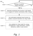
- the method 100 includes detecting whether there has been a change to the exterior shape of the vehicle combination.
- the step S101 may include detecting whether a trailer has been added and/or removed to the vehicle combination, resulting in a change of the exterior shape.
- the change may e.g. be detected by using one or more cameras monitoring the vehicle combination and, in combination with image analysis algorithms suitable for this purpose, detect changes to the vehicle combination visually.
- Other examples of how to detect the change may include e.g. a user/driver pressing a button, entering/activating a particular menu option in a user interface of the vehicle combination.
- a still further example may include e.g. detecting whether a trailer is connected or detached from the vehicle combination (using e.g. a sensor positioned at the "fifth wheel" in case of a semi-trailer, and/or a sensor positioned at e.g. a hook used to attach/detach a trailer, or similar.
- Other options may include e.g. checking whether air deflector settings changes, if it is envisaged that such deflectors are configured to adapt to optimize an air flow around the vehicle combination in terms of driving efficiency.
- Other means of detecting if there is a change in the exterior shape of the vehicle combination are of course also possible.
- step S101 If the outcome of the detection step S101 is positive ("yes"), the method 100 proceeds to a step S102. If the outcome of the detection step S101 is negative (“no"), the method 100 may repeat back to step S101 and once again check whether a change of the exterior shape is made or not.
- step S102 in response to the detection in step S101, the method 100 uses on one or more images of the vehicle combination to estimate a projected area function A p ( ⁇ ), which indicates a dependence of a projected frontal area of the vehicle combination having the new exterior shape on air-attack angle ( ⁇ ). Further details about how such an estimation may be performed will be provided later herein.
- a step S103 the method 100 uses the estimated projected area function to update a crosswind-sensitive air drag model for the vehicle combination.
- the air drag model provided by equation (1) can be used, with the newly estimated projected area function A p ( ⁇ ) replacing any older and previously used such function.
- the method 100 may optionally proceed to a step S104 in which the updated air drag model is then used for one or more computations performed in the vehicle combination, wherein these one or more computations all rely on having access to an accurate air drag model. Examples may include e.g. energy management, range estimation, vehicle combination dynamics (including e.g. vehicle combination stability in stronger crosswinds, or similar), and e.g. cruise control. Other computations which may utilize the updated air drag model (as provided by the present disclosure) are of course also possible, but not described in more detail herein.
- FIGS 2A and 2B schematically illustrate example images 200a and 200b of a vehicle combination captured by a camera, such as e.g. a digital sideview (mirror) camera.
- the vehicle combination shown in image 200a includes a towing unit (e.g. a tractor unit) 310 and one trailer 312.
- the vehicle combination shown in image 200a is a semi-trailer, wherein the trailer 312 is connected to the tractor unit 310 using a "fifth wheel".
- the trailer 312 has a side area A s 1 , which can e.g. be assumed to be known already.
- the vehicle combination shown in image 200a is assumed to be the vehicle combination before any change to the exterior shape of the vehicle combination is made.
- the vehicle combination is currently turning slightly to the right, as can be seen by the finite articulation angle between the tractor unit 310 and the trailer 312.
- Figure 200b shows the vehicle combination at a later time instance.
- a change of the exterior shape of the vehicle combination has been made, by adding an additional trailer 314 behind the trailer 312.
- a change may e.g. be detected by using image analysis to detect e.g. a number of connected trailers in each image 200a and 200b, and to note when the number of connected trailers changes.
- the change may e.g. also be detected by receiving a signal from the means used to connect the additional trailer 314 to the trailer 312, or similar.
- a side area A s 2 of the additional trailer is not known beforehand, but can be estimated from the image 200b.
- a procedure may e.g. include establishing a reference measure in the image 200b, i.e. at least one known distance/measure. For example, if a height h 1 of the trailer 312 is known in real life, measuring the distance z 1 in image 200b (e.g. by counting a number of pixels) allows to find such a reference measure.
- other parameters relevant to the capturing of the image 200b are also known. Such other parameters include e.g. a size of an image sensor in the camera used to capture the image 200b (or e.g.
- a crop-factor and aspect ratio a focal length of a lens used to capture the image 200b
- information about a position of the camera used to capture the image 200b relative to the vehicle combination and information about various articulation angles between e.g. the first trailer 312 and the tractor unit 310 and between e.g. the additional, second trailer 314 and the first trailer 312.
- a height h 2 of the additional trailer 314 is also similar or equal to the first trailer 312 (which is often the case). In other situations, it is assumed that also the height h 2 of the additional trailer 314 can also be estimated from the image 200b.
- conventional technology for obtaining real-life dimensions of an object from an image depicting the object can be used for this purpose, and that the skilled person is confident in finding and applying such procedures as required.
- one or more homographies may also be constructed/estimated in order to account for e.g. perspective distortion or similar, to facilitate determining a side surface area of a vehicle unit (or vehicle combination) based on images capturing at least part of the side surface from an angle (such as e.g. when capturing one or more images of the side of the vehicle combination using rearview and/or sideview mirror cameras, or similar).
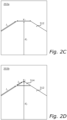
- Figures 2C and 2D schematically illustrates another example of using images of the vehicle combination to estimate the side area A s 2 of an additional trailer 314.
- the camera used to capture images of the vehicle combination is mounted on top of the vehicle combination, e.g. on a spoiler of the towing unit 310, and faces backwards such that the top of any trailers connected to the towing unit 310 are at least partially visible in the images.
- Figure 2C shows an image 202a wherein a single trailer 312 is added to the towing unit 310, just as in Figure 2A . It will here be assumed that a real-life width w, of the trailer 312 is known, as well as e.g. a real-life length l 1 of the trailer 312.
- the length l 1 may be obtained by estimating the distance d 1 in the image 202a, and to use knowledge about e.g. the position of the camera relative to the vehicle combination to find l 1 based on d 1 .
- the vehicle combination is currently driving in a straight line, and the task of estimating various parameters are therefore easier than the situation depicted in Figures 2A and 2B (where the vehicle combination was turning, and the articulation angles were finite).
- Figure 2D shows an image 202b captured at a later time instance, where the additional trailer 314 has been added.
- using image analysis and comparing the contents of the images 202a and 202b can be used to detect when the additional trailer 314 is added.
- estimating the length l 2 of the additional trailer becomes a problem of estimating a distance from the camera used to capture the image 202b to the end of the additional trailer 314.
- a focal length of the lens i.e.
- the distance d 2 from the camera to the end of the additional trailer 314 can be estimated using known procedures. By e.g. subtracting the distance d 1 from the distance d 2 , and by assuming that the gap between the trailers 312 and 314 is small, an approximation of l 2 can thus be obtained.
- the method as envisaged herein assumes that a known reference measure can be provided.
- the height of e.g. a trailer may be known and used as such a reference.
- the length of the vehicle combination, and in particular the length of a recently added trailer can then be measured directly in such a sideview image. For example, if a trailer is measured as being 500 pixels high in the image and the vehicle combination is measured as being 2500 pixels long, the length of the vehicle combination (after the change) can be estimated as 2500/500 ⁇ h, where h is a known height of the trailer being 500 pixels high. In a similar way, it is possible to calculate other measures.
- FIG 3A schematically illustrates a towing unit 310 in a top-view.
- the towing unit 310 is here a tractor unit configured to form part of a semi-trailer combination, where the trailer (not shown) is connected to the towing unit 310 using a "fifth wheel" 311.
- the towing unit 310 may instead be a truck, wherein a trailer can be added using a tow hitch and drawbar coupling.
- Figure 3A illustrates various examples of how one or more cameras 360a-c may be provided on the towing unit 310.
- the cameras 360a-c are all facing backwards, such that each of their respective fields-of-view (FOVs) 361a-c captures at least part of the trailer(s) of the vehicle combination.
- FOVs fields-of-view
- the towing unit 310 may be equipped with one or more cameras 360a and 360b acting as sideview mirrors.
- the cameras 360a and 360b may for example be configured to replace the traditional sideview mirrors, or may be provided in addition (as a compliment) to the traditional sideview mirrors.
- the camera 360c maybe provided on top of the towing unit 310 such that it may capture a top of the one or more trailers attached to the towing unit 310.
- the camera 360c may be provided on top of a spoiler (370) of the towing unit 310. It is of course envisaged that the exact number of cameras may vary. For example, only one, two or all of the cameras 360a-c may be provided. There may of course also be one or more other cameras provided than the cameras 360a-c, and configured such that they capture other angles of the one or more trailers attached to the towing unit 310.
- the one or more images of the vehicle combination may instead (or in addition) be captured by cameras provided elsewhere, such as a camera 360d forming part of a tablet or smartphone 372, or even as a camera 360e forming part of a drone/UAV 374. It is envisaged that as long as a device 400 responsible for carrying out the method 100 may communicate with such cameras in order to receive the one or more images of the vehicle combination, it is not critical in what way, and/or by what camera, the one or more images are captured.
- the device 400 may, as illustrated in Figure 3A , for example form part of the vehicle/towing unit 310, but may also (instead) form part of e.g.
- the tablet/smartphone 372, or similar equipment including processing circuitry configured to carry out the envisaged method 100.
- Other examples of cameras that may be used to capture the one or more images of the vehicle combination include e.g. speed cameras, traffic monitoring cameras, road toll cameras, cameras installed on gas-stations or resting places for truck drivers, cameras installed at weighing stations, or similar.
- Figure 3B schematically illustrates a vehicle combination 300 driving in a situation where air attacks the vehicle at an angle ⁇ , where ⁇ is measured as the angle between an air vector v a and a longitudinal direction/axis of the vehicle combination (as indicated by the dashed line 302).
- the air vector v a points in the direction of air attack at the current location of the vehicle combination 300, and has a magnitude proportional to air speed.
- the vehicle combination 300 Before the change of the exterior shape, the vehicle combination 300 has a previous projected area function A p * ⁇ (where the asterisk * is used to denote a "previous" value/function), and the change of the exterior shape (e.g. the addition or removal of one or more trailers) changes the projected area function to a new projected area function A p ( ⁇ ).
- the drag area [ C d A ]( ⁇ ) may for example be estimated as C d A ⁇ ⁇ c 1 A p ⁇ , C d A ⁇ ⁇ c 1 + c 2 tan ⁇ A p ⁇ , C d A ⁇ ⁇ c 1 + c 3 tan 2 ⁇ A p ⁇ , or C d A ⁇ ⁇ c 1 + c 2 tan ⁇ + c 3 tan 2 ⁇ A p ⁇ , where A p ( ⁇ ) is the projected area function indicating the dependence of the projected frontal area (for the vehicle combination having the new exterior shape) on air-attack angle ⁇ , and where c 1 , c 2 and c 3 are shape-parameters that may be kept constant as long as the change of the exterior shape of the vehicle combination 300 only results from a scaling of the overall vehicle combination shape. Using this approach, the drag area function [ C d A ]( ⁇ ) is updated through a
- the projected area function A p ( ⁇ ) can be estimated by assuming that the overall shape of the vehicle combination 300 is a cuboid.
- a cuboid 340 is shown in Figure 3B , and has a height h, a width w, and a length l which match the overall shape of the vehicle combination 300.
- a side 342 of the cuboid 340 corresponds to a side 322 of the vehicle combination 300, and has a side area A s .
- a front 344 of the cuboid 340 corresponds to a front 324 of the vehicle combination 300 and has a frontal area A f .
- Figure 3C shows the situation in Figure 3B from above, with the vehicle combination 300 removed leaving only the cuboid 340.
- the projected frontal area of the vehicle combination 300 is found by projecting the cuboid 340 on a plane 350 perpendicular to the air vector v a (i.e. to the air-attack). It is here assumed that the air vector has no vertical component, i.e. that the wind strikes the vehicle directly from the side and not e.g. from below or from above.
- the projection on the plane 350 is found by extending two lines 352a and 352b perpendicularly from the plane 350, and such that the two lines 352a and 352b touches a respective corner 342a and 342b of the cuboid 340.
- a change of the exterior shape of the vehicle combination 300 may include e.g. adding an additional trailer.
- Figure 3D schematically illustrates a top-view of such an example, wherein the change of the exterior shape of the vehicle combination 300 includes adding the additional trailer 314 behind the previous trailer 312. If the additional trailer 314 is added such that the gap between the trailer 312 and the additional trailer is sufficiently small (i.e.
- This solution assumes that the height h 2 of the additional trailer 314 matches that ( h 1 ) of the trailer 312, and that the frontal area A f of the vehicle combination 300 remains at least approximately the same.
- the drag area function [ C d A ]( ⁇ ) is then estimated using e.g. any of the alternatives provided by equations (2a) through (2d), resulting in an update of the air drag model of the vehicle combination 300 (as provided by equation (1)).
- a similar reasoning may of course also be applied if the change of the exterior shape of the vehicle combination 300 instead results from e.g. removing a trailer, thereby reducing the total side area A s of the vehicle combination with an area A s 2 (i.e. by making A s 2 negative).
- on-line estimation may be used to continuously improve the shape-parameters c 1 , c 2 and c 3 .
- changes to the shape-parameters c 1 , c 2 and c 3 may be required.
- Such changes may e.g. be based on available information of how the change of the exterior shape impacts the air drag. Exactly how this is performed may depend on the exact model used.
- the speed of the air causing the air drag may be divided into two components, namely longitudinal/axial air speed v ax which is opposite the vehicle (combination) longitudinal direction 302, and lateral/radial air speed v ay which is perpendicular to the vehicle (combination) longitudinal direction 302.
- the shape factor may further be divided into an axial/longitudinal shape factor C dx ( ⁇ ) affecting the axial/longitudinal air flow, and a lateral/radial shape factor C dy ( ⁇ ) affecting the lateral/radial air flow.
- the parameters c 1 , c 2 and c 3 may be adjusted according to equations (9a-c) with the parameters c x 1 , c x 2 , c y 1 and c y 2 unchanged and only adjusted according to changes in A f and A s .
- the exterior change is more related to the shape factors, like e.g. when changing an air deflector setting or adding a cover on the side of the vehicle combination in e.g.
- a f and A s may be left unchanged and c 1 , c 2 and c 3 may be adjusted to the changes in c x 1 , c x 2 , c y 1 and c y 2 .
- An exterior change may of course also be such that it causes both a change in scale and a change in scale factors, in which case the parameters c 1 , c 2 and c 3 may be adjusted both by changing A f and A s and also c x 1 , c x 2 , c y 1 and c y 2 .
- some of the parameters c x 1 , c x 2 , c y 1 and c y 2 may not be needed (and e.g. be assumed to be zero). It is envisaged to use any combination of parameters, although it is often likely that c x 1 is to be included for most applications, and that also at least one or more of the other tree parameters (or a function of them) c x 2 , c y 1 and c y 2 are needed if crosswind sensitivity is to be taken into account.
- estimating of a side area A s of the vehicle combination remains important, and is provided by using the one or more images of the vehicle combination 300 as envisaged herein.
- FIG 4A schematically illustrates, in terms of a number of functional units, the components of an embodiment of a device 400.
- the device 400 may e.g. be provided and used in the towing unit 310 (vehicle), or in other parts of the vehicle combination 300.
- the device 400 may also form part of some other equipment which may communicate with a camera used to capture the one or more images of the vehicle combination 300, such as e.g. the smartphone/table 372, the drone 372, or similar.
- the device 400 forms part of the vehicle combination 300, and preferably forms part of the towing unit 310.
- the device 400 includes processing circuitry 410.
- the processing circuitry 410 is provided using any combination of one or more of a suitable central processing unit (CPU), multiprocessor, microcontroller, digital signal processor (DSP), etc., capable of executing software instructions stored in a computer program product (not shown, but envisaged herein) stored on a storage medium 420.
- the processing circuitry 410 may further be provided as at least one application specific integrated circuit (ASIC), or field-programmable gate array (FPGA), or similar.
- ASIC application specific integrated circuit
- FPGA field-programmable gate array
- the processing circuitry 410 is configured to cause the device 400 to perform a set of operations, or steps, such as one or more of steps S101-S104 as disclosed above e.g. when describing the method 100 illustrated in Figure 1 .
- the storage medium 420 may store a set of operations
- the processing circuitry 410 may be configured to retrieve the set of operations from the storage medium 420 to cause the device 400 to perform the set of operations.
- the set of operations may be provided as a set of executable instructions.
- the processing circuitry 410 is thereby arranged to execute methods as disclosed herein e.g. with reference to Figure 1 .
- the storage medium 420 may also include persistent storage, which, for example, can be any single or combination of magnetic memory, optical memory, solid state memory or even remotely mounted memory.
- the storage medium 420 may thus provide non-transitory storage, storing computer-readable instructions for the processing circuitry 410.
- the device 400 may further include a communications interface 430 for communications with other entities and objects, in order to e.g. receive/obtain one or more of images of the vehicle combination used to estimate the projected area function A p ( ⁇ ) , and/or to e.g. detect the change of the exterior shape of the vehicle combination 300.
- the communications interface 430 may also be configured to e.g. receive information about the one or more cameras needed to estimate e.g. the side area A s 2 of an added trailer, or e.g. predicted weather information, if the estimated air drag model of the vehicle combination 300 is to be used to e.g. predict an energy consumption while driving along a route for which the predicted weather information is pertinent.
- the interface 430 may also be used to receive other information about the vehicle combination 300.
- information about the vehicle combination 300 such as e.g. information about one or more cameras 360a-360c, their positions relative to the vehicle combination 300, focal lengths of lenses, image sensor sizes, crop-factors, aspect ratios, a homography used for perspective correction, etc.
- the weather information may e.g. be stored within the device 400 itself, for example using the storage medium 420.
- the communication interface 430 may include one or more transmitters and receivers, including analogue and/or digital components, and may utilize e.g. one or more wired and/or wireless connections for this purpose.
- the processing circuitry 410 controls the general operation of the device 400 e.g. by sending data and control signals to the communications interface 430 and the storage medium 420, by receiving data and reports from the communications interface 430, and by retrieving data and instructions from the storage medium 420.
- the device 400 may of course optionally also include other components, here illustrated by the dashed box 440.
- a communication bus 450 is also provided and connects the various modules/units 410, 420, 430, and 440 (if included), such that they may communicate with each other to exchange information.
- FIG 4B schematically illustrates, in terms of a number of functional modules 401-404 (where the module 404 is optional), the components of a device 400 according to one or more embodiments of the present disclosure.
- the device 400 includes at least a detect module 401 configured to perform step S101 of the method 100 described with reference to Figure 1 , an estimate module 402 configured to perform step S102 of the method 100, and an update module 403 configured to perform step S103 of the method 100.
- the device 400 may also include a use module 404 configured to perform step S104 of the method 100 described with reference to Figure 1 .
- each functional module (such as modules 401-404) may be implemented in hardware or in software.
- one or more or all functional modules may be implemented by the processing circuitry 410, possibly in cooperation with the communications interface 430 and/or the storage medium 420.
- the processing circuitry 410 may thus be arranged to from the storage medium 420 fetch instructions as provided by one or more of the functional modules (e.g. 401-404), and to execute these instructions and thereby perform any steps of the method 100, or any other method envisaged herein, performed by the device 400 as disclosed herein.
- the device 400 may further include additional functional modules (not shown), as needed to perform one or more methods as envisaged herein.
- the present disclosure also envisages to provide a vehicle or vehicle combination (such as e.g. the towing unit 310 or vehicle combination 300), where the vehicle or vehicle combination includes the device 400 as described with reference to Figures 4A and 4B .
- a vehicle or vehicle combination such as e.g. the towing unit 310 or vehicle combination 300
- the vehicle or vehicle combination includes the device 400 as described with reference to Figures 4A and 4B .
- the present disclosure also envisages to provide a computer program for estimating air drag of/for a vehicle combination.
- the computer program includes computer code that, when running on a processing circuitry of a device (such as e.g. the processing circuitry 410 of the device 400 described with reference to Figures 4A and 4B ), causes the device to perform the various steps of any method (such as e.g. method 100) as described and envisaged herein.
- a “data carrier” may be a transitory data carrier, such as modulated electromagnetic or optical waves, or a non-transitory data carrier.
- Non-transitory data carriers include volatile and non-volatile memories, such as permanent and non-permanent storage media of magnetic, optical or solid-state type. Still within the scope of "data carrier”, such memories may be fixedly mounted or portable.
- an improved way of handling a situation in which an exterior shape of a vehicle combination changes and where an air drag model of the vehicle combination can be updated automatically after detecting such a change, using one or more images of the vehicle combination to estimate a new projected area function A p ( ⁇ ) .
- This facilitates e.g. performing of transport missions along a route which includes one or more changes to the exterior shape of the vehicle combination (such as a pick-up/drop-off of one or more trailer units).
Landscapes
- Engineering & Computer Science (AREA)
- Physics & Mathematics (AREA)
- Automation & Control Theory (AREA)
- Mathematical Physics (AREA)
- Transportation (AREA)
- Mechanical Engineering (AREA)
- General Physics & Mathematics (AREA)
- Multimedia (AREA)
- Theoretical Computer Science (AREA)
- Traffic Control Systems (AREA)
Abstract
Description
- The present disclosure relates to the field of (heavy) vehicle combinations and air drag. In particular, the present disclosure relates to estimation of an air drag model for the vehicle combination based on visual information provided by e.g. one or more images of the vehicle combination.
- When driving in crosswind conditions, the air drag force acting on heavy vehicle combinations depend on the angle of air-attack. To take such air drag into account when for example estimating a power needed to propel the vehicle combination, an air drag model is used which expresses the air drag force Fa as a function of various parameters such as air density p, the drag coefficient Cd of the vehicle combination, the projected area Ap of the vehicle combination, and e.g. the axial/longitudinal air speed vax. To account for crosswinds/sidewinds, the drag coefficient and/or the projected (frontal) area of the vehicle combination are assumed to depend on air-attack angle θ.
- To find the correct parameters for such an air drag model, wind tunnel tests are often used. Instead of finding the drag coefficient Cd (θ) and projected area Ap (θ) independently, it is often more convenient to estimate a joint drag area parameter [CdA](θ). Wind tunnel experiments/tests may also be complemented by, or even replaced by, advanced numerical simulations (such as e.g. those based on Computational Fluid Dynamics, CFD).
- The model parameters obtained from wind tunnel experiments are however only relevant as long as the exterior shape of the vehicle combination used in the wind tunnel experiments is not changed. As soon as the exterior shape of the vehicle combination changes, new wind tunnel tests and/or new numerical simulations are often required in order for the models to still remain as valid as before. As such wind tunnel tests and/or numerical simulations are often both tedious and costly, and in some situations not even feasible, the only remaining solution to find an air drag model for a new vehicle combination (having a new exterior shape) may be to perform so-called online estimation of the air drag model which includes measuring one or more relevant parameters while the vehicle combination is driving. To also estimate how the drag area depends on air-attack angle, on-line estimation techniques require access to accurate wind information while driving the vehicle combination, in order to properly capture the crosswind sensitivity of the drag area. In order for such on-line estimation to be valid, detailed knowledge about the wind that is actually affecting the vehicle combination must be known, and such knowledge may also be disturbed by e.g. various chaotic behavior of the wind caused by e.g. other vehicles driving on the same stretch of road, or similar.
- A problem with the above is that a configuration of a vehicle combination will often change during a particular transport mission, i.e. by adding or removing one or more trailers or other towed vehicle units at some points along the planned route. A driver may for example be assigned the task of picking up a first trailer at point A, deliver the first trailer to point B, and then return back with another, second trailer from point B. By not knowing how to maintain a valid air drag model of the vehicle also after having changed the exterior shape, calculations (such as for energy management, cruise control, range prediction, etc.) which rely on an access to such a valid air drag model may therefore suffer.
- There is therefore a need for an improved way of estimating air drag of/for a vehicle combination in situations when the exact configuration (e.g. the exterior shape) of the vehicle combination does not remain constant throughout a mission.
- To at least partially satisfy the above-identified need, the present disclosure provides an improved (computer-implemented) method of estimating air drag of a vehicle combination, as well as a corresponding device, vehicle or vehicle combination, computer program and computer program product as defined by the accompanying independent claims. Various embodiments of the method, device, vehicle or vehicle combination, computer program and computer program product are defined by the accompanying dependent claims.
- The method includes detecting a change of an exterior shape of the vehicle combination to a new exterior shape (i.e. a change from a previous exterior shape to the new exterior shape). The method further includes, in response to detecting such a change (of the exterior shape of the vehicle), and based on one or more images of the vehicle combination captured after the change of the exterior shape (to the new exterior shape), estimating a projected area function Ap (θ) indicating a dependence of a projected frontal area of the vehicle combination having the new exterior shape on air-attack angle θ. The method also includes using the estimated projected area function to update a crosswind-sensitive air drag model (i.e. a model depending on the air-attack angle θ) for the vehicle combination.
- The vehicle combination envisaged herein is e.g. a heavy vehicle combination, such as a utility vehicle combination including e.g. a towing unit and one or more trailers (towed units). That the estimated projected area function is used to "update a crosswind-sensitive air drag model" means that the crosswind-sensitive air drag model is such that it requires knowledge about such a function, and that any previously used such function is replaced by the (newly) estimated projected area function. Examples of such an air drag model will be provided further below in the detailed description.
- The present disclosure, and the envisaged method, improves upon currently available technology in that it, by using images of the vehicle combination, allows to determine the projected area function and to update the air drag model also when the exact shape of e.g. an added trailer is not known, where e.g. tabulated values for the exact combination of towing and towed units of the vehicle combination after the change are not available or existing, and without the need for expensive and/or cumbersome wind tunnel experiments and/or numerical simulations. In addition, the envisaged method further facilitates the process in that it automatically detects the occurrence of the change, and thereafter take appropriate action to update the air drag model. This may e.g. help to unload some of the burden from the driver, and allow the driver to instead focus on other things such as driving the vehicle in a safe way.
- In some embodiments of the method, the method may include initiating (e.g. causing a triggering of) a capture of the one or more images in response to the detecting. By so doing, the method may e.g. proceed without the need for the driver to intervene. Initiating the capture of the one or more images may for example be performed by sending a control signal to one or more cameras used to capture the one or more images. As will be explained later herein in more detail, one or more images of the vehicle combination can also be used for the detection itself, e.g. by comparing how the vehicle combination looks in one image with how the vehicle combination looks in another image, in order to detect whether the configuration (and thereby possibly also the exterior shape) of the vehicle combination has changed between the images. In this case, if the detecting initiates (e.g. triggers) the capturing of the one or more images used to estimate the projected area function, the one or more images used to detect the change are not the same one or more images used to estimate the projected area function. In other embodiments, the same one or more images used for detection of the change can also be the one or more images used to estimate the projected area function. Phrased differently, in some embodiments of the method, the method may further include detecting the change of the exterior shape based on the one or more images of the vehicle combination (i.e. based on the same one or more images used to estimate the projected area function). In such embodiments, no further capturing of images may sometimes be needed, and in an optimal case a single image may suffer both for detecting the change and for estimating the projected area function.
- In some embodiments of the method, the method may include receiving the one or more images (used to estimate the projected area function) from at least one camera. The at least one camera may be mounted to/on the vehicle combination (e.g. to a towing unit of the vehicle combination). For example, the at least one camera may be a digital rearview camera, a digital sideview (mirror) camera, camera mounted on the roof of the towing unit and facing backwards towards the one or more trailers, or similar. In other embodiments, the one or more images may instead be received e.g. from a smartphone, a camera equipped drone/UAV, a speed camera at a route along which the vehicle combination is driving, a road toll camera, a camera used to detect overloading of heavy vehicles, a traffic camera used to assess a traffic situation along the route the vehicle combination is driving, or any other camera with which the device/computer in charge of performing the envisaged method may communicate to exchange such one or more images.
- In some embodiments of the method, estimating the projected area function may include estimating a side area of the vehicle combination after the change of the exterior shape. The estimated side area may be provided as a parameter to the crosswind-sensitive air drag model. As generally used herein, a "side area" of a vehicle or vehicle combination is a side of the vehicle or vehicle combination which is not a front, rear, top or bottom side. Phrased differently, a "side area" is a surface area of a lateral side of the vehicle or vehicle combination, and can be a left side or a right side of the vehicle or vehicle combination.
- In some embodiments of the method, the one or more images may depict at least part of a side of the vehicle combination. In particular, the one or more images may depict at least a side part of e.g. an added trailer.
- In some embodiments of the method, estimating the projected area function may include estimating the projected frontal area after the change of the exterior as a projected area of a cuboid on a plane perpendicular to air-attack. Two opposite faces of this cuboid may e.g. correspond to the front and back of the vehicle combination, two other opposite faces of the cuboid may correspond to the two (lateral) left/right sides of the vehicle combination, and two other opposite faces of the cuboid may e.g. correspond to the top and bottom of the vehicle combination. Phrased differently, the cuboid may be used to approximate an overall outer shape of the vehicle combination. The projected area may for example be a parallelly projected area.
- In some embodiments of the method, detecting the change of the exterior shape may include at least one of receiving a signal from a user interface (such as e.g. when the user/driver pushes a button, selects/accesses/enters a particular menu option, or similar), receiving a signal indicative of a change in air deflector settings, and receiving a signal indicative of a trailer being either connected or detached from the vehicle combination. The detection of the change may e.g. be performed in combination with one or more sensors (or similar) available already for other purposes.
- In some embodiments of the method, the method may further include receiving a predicted wind information pertinent to a particular route, and using the updated air drag model for at least one of energy management, range estimation, vehicle combination dynamics, and cruise control, of/for the vehicle combination along the particular route. Knowledge of both the predicted wind (e.g. speed and direction) along a route which the vehicle combination is to drive may, in combination with the updated air drag model, be used to e.g. predict an energy consumption of the vehicle combination, and/or to control the speed of the vehicle combination such that both energy and time needed to reach a destination are minimized in a multi-objective fashion. Such optimization may also be performed based on various user preferences. For example, there may be certain energy consumption constraints provided and travelling time may be optimized (e.g. minimized) subject to such constraints. Likewise, a desired travelling time maybe provided in advance, and the energy consumption may be optimized (i.e. minimized) subject to such a desired travelling time.
- According to a second aspect of the present disclosure, a device for estimating air drag of a vehicle combination is provided. The device includes processing circuitry configured to cause the device to: detect a change of an exterior shape of the vehicle combination to a new exterior shape; in response to said detection, based on one or more images of the vehicle combination captured after the change of the exterior shape (to the new exterior shape), estimate a projected area function (A p(θ)) indicating a dependence of a projected frontal area of the vehicle combination having the new exterior shape on air-attack angle (θ), and, use the estimated projected area function to update a crosswind-sensitive air drag model for the vehicle combination. The device may thus be configured to perform the method of the first aspect.
- In some embodiments of the device, the processing circuitry may be further configured to cause the device to perform any embodiment of the method according envisaged and described herein.
- According to a third aspect of the present disclosure, a vehicle or vehicle combination is provided. The vehicle or vehicle combination includes a device according to the second aspect (or any embodiments thereof), configured to perform a method according to the first aspect (or any embodiments thereof).
- In some embodiments of the vehicle or vehicle combination, the vehicle or vehicle combination may include one or more cameras configured to capture and provide the one or more images used to estimate the projected area function, and/or used to detect the change of the exterior shape of the vehicle. As mentioned before, such one or more cameras may e.g. be digital rear view, side view, back up, and or overall monitoring cameras capable of capturing images of the trailers of the vehicle combination. In the envisaged method, device and vehicle or vehicle combination, it may for example be envisaged that it is easier to capture pictures of the full vehicle combination when the vehicle combination is e.g. turning (in a corner, in a circulation point/roundabout, or similar), compared to when the vehicle combination is driving in a straight line.
- According to a fourth aspect of the present disclosure, a computer program for estimating air drag of a vehicle combination is provided. The computer program includes computer code that, when running on processing circuitry of a device (such as the device of the second aspect or embodiments thereof, e.g. when included as part of the vehicle combination), causes the device to: detect a change of an exterior shape of the vehicle combination to a new exterior shape; in response to said detection, based on one or more images of the vehicle combination captured after the change of the exterior shape, estimate a projected area function (Ap (θ)) indicating a dependence of a projected frontal area of the vehicle combination having the new exterior shape on air-attack angle (θ), and, use the estimated projected area function to update a crosswind-sensitive air drag model for the vehicle combination. The computer program is thus such that it causes the device to perform a method according to the first aspect.
- In some embodiments of the computer program, the computer code may be further such that it, when running on the processing circuitry of the device, causes the device to perform any embodiment of the method as envisaged herein.
- According to a fifth aspect of the present disclosure, a computer program product is provided. The computer program product includes a computer-readable storage medium on which the computer program is stored. In some embodiments of the computer program product, the storage medium may be non-transitory.
- Other objects and advantages of the present disclosure will be apparent from the following detailed description, the drawings and the claims. Within the scope of the present disclosure, it is envisaged that all features and advantages described with reference to e.g. the method of the first aspect are relevant for, apply to, and may be used in combination with also any feature and advantage described with reference to the device of the second aspect, the vehicle (combination) of the third aspect, the computer program of the fourth aspect, and the computer program product of the fifth aspect, and vice versa.
- Exemplifying embodiments will now be described below with reference to the accompanying drawings, in which:
-
Figure 1 schematically illustrates flows of various embodiments of a method of estimating air drag according to the present disclosure; -
Figures 2A through 2D schematically illustrate various examples of one or more images which may be used to estimate a projected area function according to various embodiments of a method of air drag estimation according to the present disclosure, and -
Figures 3B through 3C schematically illustrate how a projected (frontal) area function and side area of a vehicle combination may be estimated, according to various embodiments of the present disclosure, and -
Figures 4A and 4B schematically illustrate various embodiments of a device (for air drag estimation) according to the present disclosure. - In the drawings, like reference numerals will be used for like elements unless stated otherwise. Unless explicitly stated to the contrary, the drawings show only such elements that are necessary to illustrate the example embodiments, while other elements, in the interest of clarity, may be omitted or merely suggested. As illustrated in the Figures, the (absolute or relative) sizes of elements and regions may be exaggerated or understated vis-à-vis their true values for illustrative purposes and, thus, are provided to illustrate the general structures of the embodiments.
- In what follows, the terms "vehicle" and "vehicle combination" will be used interchangeably, if not explicitly stated to the contrary. The same applies to the terms "wind" and "air" which, if not stated to the contrary, will be used interchangeably as well.
- The present disclosure envisages that when a vehicle combination moves/drives relative to the surrounding wind/air, a resulting air drag force Fa affecting the vehicle combination may be approximated as

- For many transport missions, the driver may be expected to pick-up and/or drop-off one or more vehicle units (such as e.g. trailers) along the way, and such changes to the exterior shape of the vehicle may thus affect the drag area of the vehicle combination. As the drag area influences the air drag force Fa , and as the air drag force Fa influences how hard e.g. the propulsion system of the vehicle combination must work to overcome the resistance caused by such air drag, operations such as predicting a fuel/energy consumption of the vehicle combination when driving is thus difficult if no updated air drag model can be provided. As discussed earlier herein, there are techniques available for using on-line estimation of the parameters in the air drag model, but as these techniques require knowledge about the actual air (including any turbulence and chaotic air movements caused by e.g. other vehicles), such techniques may be less reliable.
- How the present disclosure solves the above problem will now be described in more detail with references to the drawings. The figures of these drawings show exemplifying embodiments of an envisaged improved method, device, and vehicle/vehicle combination, and also serve to illustrate the concepts of an improved computer program and computer program product as also envisaged herein. The drawings show currently preferred embodiments, but the invention may, however, be embodied in many different forms and should not be construed as limited to the embodiments set forth herein; rather, these embodiments are provided for thoroughness and completeness, and fully convey the scope of the present disclosure to the skilled person.
- To illustrate the proposed method, reference is first made to
Figure 1 , which schematically illustrates a flow of an envisagedmethod 100. In a first step S101, themethod 100 includes detecting whether there has been a change to the exterior shape of the vehicle combination. For example, the step S101 may include detecting whether a trailer has been added and/or removed to the vehicle combination, resulting in a change of the exterior shape. The change may e.g. be detected by using one or more cameras monitoring the vehicle combination and, in combination with image analysis algorithms suitable for this purpose, detect changes to the vehicle combination visually. Other examples of how to detect the change may include e.g. a user/driver pressing a button, entering/activating a particular menu option in a user interface of the vehicle combination. A still further example may include e.g. detecting whether a trailer is connected or detached from the vehicle combination (using e.g. a sensor positioned at the "fifth wheel" in case of a semi-trailer, and/or a sensor positioned at e.g. a hook used to attach/detach a trailer, or similar. Other options may include e.g. checking whether air deflector settings changes, if it is envisaged that such deflectors are configured to adapt to optimize an air flow around the vehicle combination in terms of driving efficiency. Other means of detecting if there is a change in the exterior shape of the vehicle combination are of course also possible. - If the outcome of the detection step S101 is positive ("yes"), the
method 100 proceeds to a step S102. If the outcome of the detection step S101 is negative ("no"), themethod 100 may repeat back to step S101 and once again check whether a change of the exterior shape is made or not. In the step S102, in response to the detection in step S101, themethod 100 uses on one or more images of the vehicle combination to estimate a projected area function Ap (θ), which indicates a dependence of a projected frontal area of the vehicle combination having the new exterior shape on air-attack angle (θ). Further details about how such an estimation may be performed will be provided later herein. - In a step S103, the
method 100 uses the estimated projected area function to update a crosswind-sensitive air drag model for the vehicle combination. For this step, the air drag model provided by equation (1) can be used, with the newly estimated projected area function Ap (θ) replacing any older and previously used such function. - After having estimated the (new) projected area function Ap (θ) and updated the air drag model, the
method 100 may optionally proceed to a step S104 in which the updated air drag model is then used for one or more computations performed in the vehicle combination, wherein these one or more computations all rely on having access to an accurate air drag model. Examples may include e.g. energy management, range estimation, vehicle combination dynamics (including e.g. vehicle combination stability in stronger crosswinds, or similar), and e.g. cruise control. Other computations which may utilize the updated air drag model (as provided by the present disclosure) are of course also possible, but not described in more detail herein. - Various examples of how images of the vehicle combination can be used to estimate the projected area function Ap (θ) of the vehicle combination, will now be described in more detail with reference also to
Figures 2A through 2D , andFigures 3A through 3D . -
Figures 2A and 2B schematically illustrateexample images image 200a includes a towing unit (e.g. a tractor unit) 310 and onetrailer 312. Phrased differently, the vehicle combination shown inimage 200a is a semi-trailer, wherein thetrailer 312 is connected to thetractor unit 310 using a "fifth wheel". Thetrailer 312 has a side area A s1, which can e.g. be assumed to be known already. For the purpose of the present example, the vehicle combination shown inimage 200a is assumed to be the vehicle combination before any change to the exterior shape of the vehicle combination is made. Inimage 200a, the vehicle combination is currently turning slightly to the right, as can be seen by the finite articulation angle between thetractor unit 310 and thetrailer 312. - Figure 200b shows the vehicle combination at a later time instance. Now, a change of the exterior shape of the vehicle combination has been made, by adding an
additional trailer 314 behind thetrailer 312. As envisaged herein, such a change may e.g. be detected by using image analysis to detect e.g. a number of connected trailers in eachimage additional trailer 314 to thetrailer 312, or similar. - The proposed method envisages that a side area A s2 of the additional trailer is not known beforehand, but can be estimated from the
image 200b. Such a procedure may e.g. include establishing a reference measure in theimage 200b, i.e. at least one known distance/measure. For example, if a height h 1 of thetrailer 312 is known in real life, measuring the distance z 1 inimage 200b (e.g. by counting a number of pixels) allows to find such a reference measure. It is further assumed that other parameters relevant to the capturing of theimage 200b are also known. Such other parameters include e.g. a size of an image sensor in the camera used to capture theimage 200b (or e.g. a crop-factor and aspect ratio), a focal length of a lens used to capture theimage 200b, information about a position of the camera used to capture theimage 200b relative to the vehicle combination, and information about various articulation angles between e.g. thefirst trailer 312 and thetractor unit 310 and between e.g. the additional,second trailer 314 and thefirst trailer 312. It can also be assumed that a height h 2 of theadditional trailer 314 is also similar or equal to the first trailer 312 (which is often the case). In other situations, it is assumed that also the height h 2 of theadditional trailer 314 can also be estimated from theimage 200b. If for example being able to estimate, from theimage 200b and the above-mentioned other parameters, the length l 2 of theadditional trailer 314, the side area A s2 of theadditional trailer 314 can then be estimated simply as A s2 = h 2 × l 2. In any case, it is herein assumed that conventional technology for obtaining real-life dimensions of an object from an image depicting the object can be used for this purpose, and that the skilled person is confident in finding and applying such procedures as required. - In addition to the above, it is envisaged that also one or more homographies may also be constructed/estimated in order to account for e.g. perspective distortion or similar, to facilitate determining a side surface area of a vehicle unit (or vehicle combination) based on images capturing at least part of the side surface from an angle (such as e.g. when capturing one or more images of the side of the vehicle combination using rearview and/or sideview mirror cameras, or similar).
-
Figures 2C and 2D schematically illustrates another example of using images of the vehicle combination to estimate the side area A s2 of anadditional trailer 314. Here, the camera used to capture images of the vehicle combination is mounted on top of the vehicle combination, e.g. on a spoiler of thetowing unit 310, and faces backwards such that the top of any trailers connected to thetowing unit 310 are at least partially visible in the images.Figure 2C shows animage 202a wherein asingle trailer 312 is added to thetowing unit 310, just as inFigure 2A . It will here be assumed that a real-life width w, of thetrailer 312 is known, as well as e.g. a real-life length l 1 of thetrailer 312. In another example, the length l 1 may be obtained by estimating the distance d 1 in theimage 202a, and to use knowledge about e.g. the position of the camera relative to the vehicle combination to find l 1 based on d 1. In the situation depicted inFigures 2C and 2D , the vehicle combination is currently driving in a straight line, and the task of estimating various parameters are therefore easier than the situation depicted inFigures 2A and 2B (where the vehicle combination was turning, and the articulation angles were finite). -
Figure 2D shows animage 202b captured at a later time instance, where theadditional trailer 314 has been added. As mentioned earlier, using image analysis and comparing the contents of theimages additional trailer 314 is added. Now, if the length l 1 of thetrailer 312 is known, estimating the length l 2 of the additional trailer becomes a problem of estimating a distance from the camera used to capture theimage 202b to the end of theadditional trailer 314. If having knowledge about the size of the image sensor of the camera (or a crop-factor and aspect ratio), a focal length of the lens, and by measuring the distance y2 inimage 202b (i.e. by counting pixels), the distance d 2 from the camera to the end of theadditional trailer 314 can be estimated using known procedures. By e.g. subtracting the distance d 1 from the distance d 2, and by assuming that the gap between thetrailers additional trailer 314 matches a known height h 1 of thefirst trailer 312, the side area of theadditional trailer 314 is given simply as A s2 = h 2 × l 2. In summary, using any of the methods described with reference toFigures 2A through 2D , it is envisaged that an estimation of the side area A S2 of the additional trailer (causing the change in the exterior shape of the vehicle combination) can be obtained from the images of the vehicle combination. - In general, the method as envisaged herein assumes that a known reference measure can be provided. For example, in an image captured such that it shows the vehicle combination from the side, the height of e.g. a trailer may be known and used as such a reference. The length of the vehicle combination, and in particular the length of a recently added trailer, can then be measured directly in such a sideview image. For example, if a trailer is measured as being 500 pixels high in the image and the vehicle combination is measured as being 2500 pixels long, the length of the vehicle combination (after the change) can be estimated as 2500/500 × h, where h is a known height of the trailer being 500 pixels high. In a similar way, it is possible to calculate other measures. As shown with reference to
Figures 2A and 2B , such calculations may be more complicated if the image does not depict the vehicle combination from the side, but e.g. as captured by a digital side view mirror or similar. In such a situation, information about e.g. articulation angles, camera parameters, camera orientation and placement relative to the vehicle combination, etc., may also be required before being able to calculate the necessary parameters needed to estimate the projected area function Ap (θ). -
Figure 3A schematically illustrates atowing unit 310 in a top-view. Thetowing unit 310 is here a tractor unit configured to form part of a semi-trailer combination, where the trailer (not shown) is connected to thetowing unit 310 using a "fifth wheel" 311. In other examples, thetowing unit 310 may instead be a truck, wherein a trailer can be added using a tow hitch and drawbar coupling.Figure 3A illustrates various examples of how one ormore cameras 360a-c may be provided on thetowing unit 310. Thecameras 360a-c are all facing backwards, such that each of their respective fields-of-view (FOVs) 361a-c captures at least part of the trailer(s) of the vehicle combination. For example, thetowing unit 310 may be equipped with one ormore cameras cameras towing unit 310 such that it may capture a top of the one or more trailers attached to thetowing unit 310. For example, the camera 360c may be provided on top of a spoiler (370) of thetowing unit 310. It is of course envisaged that the exact number of cameras may vary. For example, only one, two or all of thecameras 360a-c may be provided. There may of course also be one or more other cameras provided than thecameras 360a-c, and configured such that they capture other angles of the one or more trailers attached to thetowing unit 310. - In other embodiments of e.g. a method as envisaged herein, the one or more images of the vehicle combination may instead (or in addition) be captured by cameras provided elsewhere, such as a
camera 360d forming part of a tablet orsmartphone 372, or even as acamera 360e forming part of a drone/UAV 374. It is envisaged that as long as adevice 400 responsible for carrying out themethod 100 may communicate with such cameras in order to receive the one or more images of the vehicle combination, it is not critical in what way, and/or by what camera, the one or more images are captured. Thedevice 400 may, as illustrated inFigure 3A , for example form part of the vehicle/towing unit 310, but may also (instead) form part of e.g. a trailer, the tablet/smartphone 372, or similar equipment including processing circuitry configured to carry out the envisagedmethod 100. Other examples of cameras that may be used to capture the one or more images of the vehicle combination include e.g. speed cameras, traffic monitoring cameras, road toll cameras, cameras installed on gas-stations or resting places for truck drivers, cameras installed at weighing stations, or similar. - How knowledge about the side area A s2 of the added
trailer 314 can be used to estimate the projected area function Ap (θ) will now be described in more detail with reference in particular toFigures 3B through 3D . -
Figure 3B schematically illustrates avehicle combination 300 driving in a situation where air attacks the vehicle at an angle θ, where θ is measured as the angle between an air vector va and a longitudinal direction/axis of the vehicle combination (as indicated by the dashed line 302). The air vector va points in the direction of air attack at the current location of thevehicle combination 300, and has a magnitude proportional to air speed. - Before the change of the exterior shape, the
vehicle combination 300 has a previous projected area function
vehicle combination 300 is required in order to also estimate a new cross-wind sensitive drag area [CdA](θ) of thevehicle combination 300, as the drag area [CdA](θ) forms part of the air drag model of thevehicle combination 300 as provided by equation (1). - The drag area [CdA](θ) may for example be estimated as


vehicle combination 300 only results from a scaling of the overall vehicle combination shape. Using this approach, the drag area function [CdA](θ) is updated through a change in the projected area function Ap (θ). - Unless better information is available, the projected area function Ap (θ) can be estimated by assuming that the overall shape of the
vehicle combination 300 is a cuboid. Such a cuboid 340 is shown inFigure 3B , and has a height h, a width w, and a length l which match the overall shape of thevehicle combination 300. Aside 342 of the cuboid 340 corresponds to aside 322 of thevehicle combination 300, and has a side area As . Similarly, afront 344 of the cuboid 340 corresponds to afront 324 of thevehicle combination 300 and has a frontal area Af . The side and frontal areas are thus given by As = l x h and Af = w x h. -
Figure 3C shows the situation inFigure 3B from above, with thevehicle combination 300 removed leaving only the cuboid 340. The projected frontal area of thevehicle combination 300 is found by projecting the cuboid 340 on aplane 350 perpendicular to the air vector va (i.e. to the air-attack). It is here assumed that the air vector has no vertical component, i.e. that the wind strikes the vehicle directly from the side and not e.g. from below or from above. The projection on theplane 350 is found by extending twolines plane 350, and such that the twolines respective corner plane 350, and the resulting projected frontal area is provided by the distance l' = l 1 + l 2 times the height h of the cuboid. Using trigonometry, it is found that l 1 = (Af /h)cos(θ) and l 2 = (AS /h)sin(θ), and the projected frontal area is thus provided as
- If it is envisaged that a removal or addition of one or more vehicle units (such as trailers or other towed units) only affects the total side area As of the
vehicle combination 300, and leaves the front area Af unchanged, the new projected area function is thus found by modifying As . In some examples of the envisaged method, a change of the exterior shape of thevehicle combination 300 may include e.g. adding an additional trailer. -
Figure 3D schematically illustrates a top-view of such an example, wherein the change of the exterior shape of thevehicle combination 300 includes adding theadditional trailer 314 behind theprevious trailer 312. If theadditional trailer 314 is added such that the gap between thetrailer 312 and the additional trailer is sufficiently small (i.e. such thattrailer 312 is shadowing the additional trailer 314), the new projected area function may be found by changing the side area As above according to

vehicle combination 300 including only the towing unit 310 (having side area As,tractor ) and trailer 312 (having side area A s1), and where A s2 is the side area of theadditional trailer 314. This solution assumes that the height h 2 of theadditional trailer 314 matches that (h 1) of thetrailer 312, and that the frontal area Af of thevehicle combination 300 remains at least approximately the same. - In the above situation, the new projected frontal area (in the air-attack direction) may be defined as

- After having estimated the new projected area function Ap (θ), the drag area function [CdA](θ) is then estimated using e.g. any of the alternatives provided by equations (2a) through (2d), resulting in an update of the air drag model of the vehicle combination 300 (as provided by equation (1)).
- A similar reasoning may of course also be applied if the change of the exterior shape of the
vehicle combination 300 instead results from e.g. removing a trailer, thereby reducing the total side area As of the vehicle combination with an area A s2 (i.e. by making A s2 negative). - As envisaged herein, on-line estimation may be used to continuously improve the shape-parameters c 1, c 2 and c 3. For example, if the change of the exterior shape of the
vehicle combination 300 is not just a scaling, changes to the shape-parameters c 1, c 2 and c 3 may be required. Such changes may e.g. be based on available information of how the change of the exterior shape impacts the air drag. Exactly how this is performed may depend on the exact model used. - In what follows, a general outline of how to construct a model which is applicable when the change of the exterior shape does not only result in a scaling will now be provided.
- For example, it may be assumed that the speed of the air causing the air drag may be divided into two components, namely longitudinal/axial air speed vax which is opposite the vehicle (combination)
longitudinal direction 302, and lateral/radial air speed vay which is perpendicular to the vehicle (combination)longitudinal direction 302. The drag area function [CdA](θ) may then be divided into a shape factor Cd (θ) and area projection in air-attack angle Ap (θ), i.e. such that
- The shape factor may further be divided into an axial/longitudinal shape factor Cdx (θ) affecting the axial/longitudinal air flow, and a lateral/radial shape factor Cdy (θ) affecting the lateral/radial air flow. These factors may be approximated as


- The air drag from the axial/longitudinal air and air drag from the lateral/radial air may be written as


- The parameters c 1, c 2 and c 3 may then be calculated as


- Using this modified approach, when the exterior of the vehicle combination is changed in a way similar to scaling, the parameters c 1, c 2 and c 3 may be adjusted according to equations (9a-c) with the parameters c x1, c x2, c y1 and c y2 unchanged and only adjusted according to changes in Af and As . On the other hand, if the exterior change is more related to the shape factors, like e.g. when changing an air deflector setting or adding a cover on the side of the vehicle combination in e.g. an attempt to reduce the effects of crosswind-generated air drag, Af and As may be left unchanged and c 1, c 2 and c 3 may be adjusted to the changes in c x1, c x2, c y1 and c y2. An exterior change may of course also be such that it causes both a change in scale and a change in scale factors, in which case the parameters c 1, c 2 and c 3 may be adjusted both by changing Af and As and also c x1, c x2, c y1 and c y2.
- In some embodiments, some of the parameters c x1, c x2, c y1 and c y2 may not be needed (and e.g. be assumed to be zero). It is envisaged to use any combination of parameters, although it is often likely that c x1 is to be included for most applications, and that also at least one or more of the other tree parameters (or a function of them) c x2, c y1 and c y2 are needed if crosswind sensitivity is to be taken into account.
- Importantly, even if consider scaling-only or taking other shape-changes into account, estimating of a side area As of the vehicle combination remains important, and is provided by using the one or more images of the
vehicle combination 300 as envisaged herein. - With reference to
Figures 4A and 4B , various embodiments of a device as envisaged herein will now be described in more detail. -
Figure 4A schematically illustrates, in terms of a number of functional units, the components of an embodiment of adevice 400. Thedevice 400 may e.g. be provided and used in the towing unit 310 (vehicle), or in other parts of thevehicle combination 300. Thedevice 400 may also form part of some other equipment which may communicate with a camera used to capture the one or more images of thevehicle combination 300, such as e.g. the smartphone/table 372, thedrone 372, or similar. In a preferred embodiment, thedevice 400 forms part of thevehicle combination 300, and preferably forms part of thetowing unit 310. - The
device 400 includesprocessing circuitry 410. Theprocessing circuitry 410 is provided using any combination of one or more of a suitable central processing unit (CPU), multiprocessor, microcontroller, digital signal processor (DSP), etc., capable of executing software instructions stored in a computer program product (not shown, but envisaged herein) stored on astorage medium 420. Theprocessing circuitry 410 may further be provided as at least one application specific integrated circuit (ASIC), or field-programmable gate array (FPGA), or similar. - Particularly, the
processing circuitry 410 is configured to cause thedevice 400 to perform a set of operations, or steps, such as one or more of steps S101-S104 as disclosed above e.g. when describing themethod 100 illustrated inFigure 1 . For example, thestorage medium 420 may store a set of operations, and theprocessing circuitry 410 may be configured to retrieve the set of operations from thestorage medium 420 to cause thedevice 400 to perform the set of operations. The set of operations may be provided as a set of executable instructions. Thus, theprocessing circuitry 410 is thereby arranged to execute methods as disclosed herein e.g. with reference toFigure 1 . - The
storage medium 420 may also include persistent storage, which, for example, can be any single or combination of magnetic memory, optical memory, solid state memory or even remotely mounted memory. Thestorage medium 420 may thus provide non-transitory storage, storing computer-readable instructions for theprocessing circuitry 410. - The
device 400 may further include a communications interface 430 for communications with other entities and objects, in order to e.g. receive/obtain one or more of images of the vehicle combination used to estimate the projected area function Ap (θ), and/or to e.g. detect the change of the exterior shape of thevehicle combination 300. The communications interface 430 may also be configured to e.g. receive information about the one or more cameras needed to estimate e.g. the side area A s2 of an added trailer, or e.g. predicted weather information, if the estimated air drag model of thevehicle combination 300 is to be used to e.g. predict an energy consumption while driving along a route for which the predicted weather information is pertinent. The interface 430 may also be used to receive other information about thevehicle combination 300. In other embodiments of thedevice 400, information about the vehicle combination 300 (such as e.g. information about one ormore cameras 360a-360c, their positions relative to thevehicle combination 300, focal lengths of lenses, image sensor sizes, crop-factors, aspect ratios, a homography used for perspective correction, etc.), and/or the weather information may e.g. be stored within thedevice 400 itself, for example using thestorage medium 420. The communication interface 430 may include one or more transmitters and receivers, including analogue and/or digital components, and may utilize e.g. one or more wired and/or wireless connections for this purpose. - The
processing circuitry 410 controls the general operation of thedevice 400 e.g. by sending data and control signals to the communications interface 430 and thestorage medium 420, by receiving data and reports from the communications interface 430, and by retrieving data and instructions from thestorage medium 420. Thedevice 400 may of course optionally also include other components, here illustrated by the dashedbox 440. Acommunication bus 450 is also provided and connects the various modules/units -
Figure 4B schematically illustrates, in terms of a number of functional modules 401-404 (where themodule 404 is optional), the components of adevice 400 according to one or more embodiments of the present disclosure. Thedevice 400 includes at least a detectmodule 401 configured to perform step S101 of themethod 100 described with reference toFigure 1 , anestimate module 402 configured to perform step S102 of themethod 100, and anupdate module 403 configured to perform step S103 of themethod 100. In some embodiments, thedevice 400 may also include ause module 404 configured to perform step S104 of themethod 100 described with reference toFigure 1 . - In general terms, each functional module (such as modules 401-404) may be implemented in hardware or in software. Preferably, one or more or all functional modules may be implemented by the
processing circuitry 410, possibly in cooperation with the communications interface 430 and/or thestorage medium 420. Theprocessing circuitry 410 may thus be arranged to from thestorage medium 420 fetch instructions as provided by one or more of the functional modules (e.g. 401-404), and to execute these instructions and thereby perform any steps of themethod 100, or any other method envisaged herein, performed by thedevice 400 as disclosed herein. - In some embodiments, the
device 400 may further include additional functional modules (not shown), as needed to perform one or more methods as envisaged herein. - The present disclosure also envisages to provide a vehicle or vehicle combination (such as e.g. the
towing unit 310 or vehicle combination 300), where the vehicle or vehicle combination includes thedevice 400 as described with reference toFigures 4A and 4B . - The present disclosure also envisages to provide a computer program for estimating air drag of/for a vehicle combination. The computer program includes computer code that, when running on a processing circuitry of a device (such as e.g. the
processing circuitry 410 of thedevice 400 described with reference toFigures 4A and 4B ), causes the device to perform the various steps of any method (such as e.g. method 100) as described and envisaged herein. - The present disclosure also envisages a computer program product (not shown) in which the above envisaged computer program is stored or distributed on a data carrier. As used herein, a "data carrier" may be a transitory data carrier, such as modulated electromagnetic or optical waves, or a non-transitory data carrier. Non-transitory data carriers include volatile and non-volatile memories, such as permanent and non-permanent storage media of magnetic, optical or solid-state type. Still within the scope of "data carrier", such memories may be fixedly mounted or portable.
- Although features and elements may be described above in particular combinations, each feature or element may be used alone without the other features and elements or in various combinations with or without other features and elements. Additionally, variations to the disclosed embodiments may be understood and effected by the skilled person in practicing the claimed invention, from a study of the drawings, the disclosure, and the appended claims.
- In the claims, the words "comprising" and "including" does not exclude other elements, and the indefinite article "a" or "an" does not exclude a plurality. The mere fact that certain features are recited in mutually different dependent claims does not indicate that a combination of these features cannot be used to advantage.
- In summary of the present disclosure, it is provided an improved way of handling a situation in which an exterior shape of a vehicle combination changes, and where an air drag model of the vehicle combination can be updated automatically after detecting such a change, using one or more images of the vehicle combination to estimate a new projected area function Ap (θ). This facilitates e.g. performing of transport missions along a route which includes one or more changes to the exterior shape of the vehicle combination (such as a pick-up/drop-off of one or more trailer units). This in contrast to commonly available technology, wherein the drag area of the changed vehicle combination must either be obtained by on-line estimation, wind tunnel tests/experiments, numerical simulations, and/or by tabular values.
Claims (15)
- A computer-implemented method (100) of estimating air drag of a vehicle combination (300), the method comprising:- detecting (S101) a change of an exterior shape of the vehicle combination to a new exterior shape;- in response to detecting such a change, based on one or more images (200b, 202b) of the vehicle combination captured after the change of the exterior shape, estimating (S102) a projected area function (A p(θ)) indicating a dependence of a projected frontal area of the vehicle combination having the new exterior shape on air-attack angle (θ), and- using the estimated projected area function to update (S103) a crosswind-sensitive air drag model for the vehicle combination.
- The method according to claim 1, wherein the method includes initiating a capture of the one or more images in response to said detecting.
- The method according to claim 1 or 2, wherein the method includes receiving the one or more images from at least one camera (360a, 360b, 360c) mounted to/on the vehicle combination.
- The method according to any one of claims 1 to 3, wherein estimating the projected area function includes estimating a side area (As ) of the vehicle combination after the change of the exterior shape.
- The method according to claim 4, wherein the one or more images depict at least part of a side (322) of the vehicle combination.
- The method according to claim 4 or 5, wherein estimating the projected area function includes estimating the projected frontal area after the change of the exterior shape as a projected area of a cuboid (340) on a plane (350) perpendicular to air-attack (va ).
- The method according to any one of the preceding claims, wherein the method further includes detecting the change of the exterior shape based on the one or more images (200a-b, 202a-b) of the vehicle combination.
- The method according to any one of the preceding claims, wherein detecting the change of the exterior shape includes at least one of receiving a signal from a user interface of the vehicle combination, receiving a signal indicative of a change in air deflector settings, and receiving a signal indicative of a trailer (314) being either connected or detached from the vehicle combination.
- The method according to any one of the preceding claims, wherein the method further includes receiving predicted wind information pertinent to a particular route, and using (S104) the updated air drag model for at least one of energy management, range estimation, vehicle combination dynamics, and cruise control, of the vehicle combination along the particular route.
- A device (400) for estimating air drag of a vehicle combination (300), comprising processing circuitry (410) configured to cause the device to:- detect (S101) a change of an exterior shape of the vehicle combination to a new exterior shape;- in response to said detection, based on one or more images (200b, 202b) of the vehicle combination captured after the change of the exterior shape,estimate (S102) a projected area function (A p(θ)) indicating a dependence of a projected frontal area of the vehicle combination having the new exterior shape on air-attack angle (θ), and- use (S103) the estimated projected area function to update a crosswind-sensitive air drag model for the vehicle combination.
- The device according to claim 10, wherein the processing circuitry is further configured to cause the device to perform a method (100) according to any one of claims 2 to 9.
- A vehicle (310) or vehicle combination (300), comprising a device (400) according to claim 10 or 11.
- A computer program for estimating air drag of a vehicle combination (300), the computer program comprising computer code that, when running on processing circuitry (410) of a device (400), causes the device to:- detect (S101) a change of an exterior shape of the vehicle combination to a new exterior shape;- in response to said detection, based on one or more images (200b, 202b) of the vehicle combination captured after the change of the exterior shape,estimate (S102) a projected area function (Ap (θ)) indicating a dependence of a projected frontal area of the vehicle combination having the new exterior shape on air-attack angle (θ), and- use (S103) the estimated projected area function to update a crosswind-sensitive air drag model for the vehicle combination.
- The computer program according to claim 13, wherein the computer code is further such that it, when running on the processing circuitry of the device, causes the device to perform a method (100) according to any one of claims 2 to 9.
- A computer program product comprising a computer program according to claim 13 or 14, and a computer-readable storage medium on which the computer program is stored.
Priority Applications (2)
| Application Number | Priority Date | Filing Date | Title |
|---|---|---|---|
| EP22175819.6A EP4282726B1 (en) | 2022-05-27 | 2022-05-27 | Air drag model estimation using visual information |
| US18/320,647 US20230382402A1 (en) | 2022-05-27 | 2023-05-19 | Air drag model estimation using visual information |
Applications Claiming Priority (1)
| Application Number | Priority Date | Filing Date | Title |
|---|---|---|---|
| EP22175819.6A EP4282726B1 (en) | 2022-05-27 | 2022-05-27 | Air drag model estimation using visual information |
Publications (3)
| Publication Number | Publication Date |
|---|---|
| EP4282726A1 true EP4282726A1 (en) | 2023-11-29 |
| EP4282726B1 EP4282726B1 (en) | 2024-06-26 |
| EP4282726C0 EP4282726C0 (en) | 2024-06-26 |
Family
ID=82446624
Family Applications (1)
| Application Number | Title | Priority Date | Filing Date |
|---|---|---|---|
| EP22175819.6A Active EP4282726B1 (en) | 2022-05-27 | 2022-05-27 | Air drag model estimation using visual information |
Country Status (2)
| Country | Link |
|---|---|
| US (1) | US20230382402A1 (en) |
| EP (1) | EP4282726B1 (en) |
Citations (3)
| Publication number | Priority date | Publication date | Assignee | Title |
|---|---|---|---|---|
| JP2014113905A (en) * | 2012-12-10 | 2014-06-26 | Honda Motor Co Ltd | Disturbance suppression control system and disturbance display device |
| DE102019211753A1 (en) * | 2019-08-06 | 2021-02-11 | Volkswagen Aktiengesellschaft | Method and system for determining the trailer weight of a trailer coupled to a motor vehicle |
| US20210197837A1 (en) * | 2017-10-12 | 2021-07-01 | Vitesco Technologies GmbH | Method and System for Determining Effective Wind Speeds for Motor Vehicles |
-
2022
- 2022-05-27 EP EP22175819.6A patent/EP4282726B1/en active Active
-
2023
- 2023-05-19 US US18/320,647 patent/US20230382402A1/en active Pending
Patent Citations (3)
| Publication number | Priority date | Publication date | Assignee | Title |
|---|---|---|---|---|
| JP2014113905A (en) * | 2012-12-10 | 2014-06-26 | Honda Motor Co Ltd | Disturbance suppression control system and disturbance display device |
| US20210197837A1 (en) * | 2017-10-12 | 2021-07-01 | Vitesco Technologies GmbH | Method and System for Determining Effective Wind Speeds for Motor Vehicles |
| DE102019211753A1 (en) * | 2019-08-06 | 2021-02-11 | Volkswagen Aktiengesellschaft | Method and system for determining the trailer weight of a trailer coupled to a motor vehicle |
Also Published As
| Publication number | Publication date |
|---|---|
| US20230382402A1 (en) | 2023-11-30 |
| EP4282726B1 (en) | 2024-06-26 |
| EP4282726C0 (en) | 2024-06-26 |
Similar Documents
| Publication | Publication Date | Title |
|---|---|---|
| US10346705B2 (en) | Method and apparatus for estimating articulation angle | |
| US11669091B2 (en) | Configuring motion planning for a self-driving tractor unit | |
| US11377029B2 (en) | Vehicular trailering assist system with trailer state estimation | |
| JP7124114B2 (en) | Apparatus and method for determining the center of a trailer tow coupler | |
| US12043283B2 (en) | Detection of near-range and far-range small objects for autonomous vehicles | |
| US11983969B2 (en) | Systems and methods for modeling electric vehicle towing | |
| JP6008605B2 (en) | TOWED VEHICLE WHEELBASE DETECTING DEVICE AND VEHICLE CONTROL DEVICE HAVING TOWED VEHICLE WHEELBASE DETECTING DEVICE | |
| CN110411530A (en) | A kind of intelligent identification Method of container residual volume | |
| CN106274685A (en) | Use HMI to assist the intelligent tow truck of visual servo to couple to control | |
| US20210034903A1 (en) | Trailer hitching assist system with trailer coupler detection | |
| CN105141945A (en) | Surround-view camera system (vpm) online calibration | |
| JP6789010B2 (en) | Driving support device, driving support method, imaging device, and vehicle | |
| CN109472251B (en) | Object collision prediction method and device | |
| CN103227905B (en) | Exposure controller for on-vehicle camera | |
| CN114763136A (en) | Guide vehicle driving auxiliary system based on deep learning | |
| CN114913329A (en) | Image processing method, semantic segmentation network training method and device | |
| CN113239459A (en) | Target screening method, screening system, electronic device, and storage medium | |
| EP4282726B1 (en) | Air drag model estimation using visual information | |
| US12142059B2 (en) | System and method for dynamic dimensioning of vehicle and trailer from shadow profiling | |
| CN116823693A (en) | Trailer view imaging method, device, equipment and storage medium | |
| CN110598505B (en) | Obstacle suspension state judging method, device and terminal | |
| US20230215045A1 (en) | On-vehicle camera alignment monitoring system | |
| US20230385489A1 (en) | Prediction of vehicle combination drag area including crosswind sensitivity | |
| EP4435378A1 (en) | Connection angle detection apparatus for combination vehicle, combination vehicle, and method for detecting connection angle of combination vehicle | |
| US20240051359A1 (en) | Object position estimation with calibrated sensors |
Legal Events
| Date | Code | Title | Description |
|---|---|---|---|
| PUAI | Public reference made under article 153(3) epc to a published international application that has entered the european phase |
Free format text: ORIGINAL CODE: 0009012 |
|
| STAA | Information on the status of an ep patent application or granted ep patent |
Free format text: STATUS: REQUEST FOR EXAMINATION WAS MADE |
|
| 17P | Request for examination filed |
Effective date: 20230215 |
|
| AK | Designated contracting states |
Kind code of ref document: A1 Designated state(s): AL AT BE BG CH CY CZ DE DK EE ES FI FR GB GR HR HU IE IS IT LI LT LU LV MC MK MT NL NO PL PT RO RS SE SI SK SM TR |
|
| GRAP | Despatch of communication of intention to grant a patent |
Free format text: ORIGINAL CODE: EPIDOSNIGR1 |
|
| STAA | Information on the status of an ep patent application or granted ep patent |
Free format text: STATUS: GRANT OF PATENT IS INTENDED |
|
| INTG | Intention to grant announced |
Effective date: 20240115 |
|
| GRAS | Grant fee paid |
Free format text: ORIGINAL CODE: EPIDOSNIGR3 |
|
| GRAA | (expected) grant |
Free format text: ORIGINAL CODE: 0009210 |
|
| STAA | Information on the status of an ep patent application or granted ep patent |
Free format text: STATUS: THE PATENT HAS BEEN GRANTED |
|
| AK | Designated contracting states |
Kind code of ref document: B1 Designated state(s): AL AT BE BG CH CY CZ DE DK EE ES FI FR GB GR HR HU IE IS IT LI LT LU LV MC MK MT NL NO PL PT RO RS SE SI SK SM TR |
|
| REG | Reference to a national code |
Ref country code: GB Ref legal event code: FG4D |
|
| REG | Reference to a national code |
Ref country code: CH Ref legal event code: EP |
|
| REG | Reference to a national code |
Ref country code: DE Ref legal event code: R096 Ref document number: 602022004113 Country of ref document: DE |
|
| U01 | Request for unitary effect filed |
Effective date: 20240703 |
|
| U07 | Unitary effect registered |
Designated state(s): AT BE BG DE DK EE FI FR IT LT LU LV MT NL PT SE SI Effective date: 20240710 |
|
| PG25 | Lapsed in a contracting state [announced via postgrant information from national office to epo] |
Ref country code: HR Free format text: LAPSE BECAUSE OF FAILURE TO SUBMIT A TRANSLATION OF THE DESCRIPTION OR TO PAY THE FEE WITHIN THE PRESCRIBED TIME-LIMIT Effective date: 20240626 |
|
| PG25 | Lapsed in a contracting state [announced via postgrant information from national office to epo] |
Ref country code: GR Free format text: LAPSE BECAUSE OF FAILURE TO SUBMIT A TRANSLATION OF THE DESCRIPTION OR TO PAY THE FEE WITHIN THE PRESCRIBED TIME-LIMIT Effective date: 20240927 |
|
| PG25 | Lapsed in a contracting state [announced via postgrant information from national office to epo] |
Ref country code: NO Free format text: LAPSE BECAUSE OF FAILURE TO SUBMIT A TRANSLATION OF THE DESCRIPTION OR TO PAY THE FEE WITHIN THE PRESCRIBED TIME-LIMIT Effective date: 20240926 Ref country code: HR Free format text: LAPSE BECAUSE OF FAILURE TO SUBMIT A TRANSLATION OF THE DESCRIPTION OR TO PAY THE FEE WITHIN THE PRESCRIBED TIME-LIMIT Effective date: 20240626 Ref country code: GR Free format text: LAPSE BECAUSE OF FAILURE TO SUBMIT A TRANSLATION OF THE DESCRIPTION OR TO PAY THE FEE WITHIN THE PRESCRIBED TIME-LIMIT Effective date: 20240927 Ref country code: RS Free format text: LAPSE BECAUSE OF FAILURE TO SUBMIT A TRANSLATION OF THE DESCRIPTION OR TO PAY THE FEE WITHIN THE PRESCRIBED TIME-LIMIT Effective date: 20240926 |
|
| PG25 | Lapsed in a contracting state [announced via postgrant information from national office to epo] |
Ref country code: PL Free format text: LAPSE BECAUSE OF FAILURE TO SUBMIT A TRANSLATION OF THE DESCRIPTION OR TO PAY THE FEE WITHIN THE PRESCRIBED TIME-LIMIT Effective date: 20240626 |
|
| PG25 | Lapsed in a contracting state [announced via postgrant information from national office to epo] |
Ref country code: IS Free format text: LAPSE BECAUSE OF FAILURE TO SUBMIT A TRANSLATION OF THE DESCRIPTION OR TO PAY THE FEE WITHIN THE PRESCRIBED TIME-LIMIT Effective date: 20241026 |
|
| PG25 | Lapsed in a contracting state [announced via postgrant information from national office to epo] |
Ref country code: CZ Free format text: LAPSE BECAUSE OF FAILURE TO SUBMIT A TRANSLATION OF THE DESCRIPTION OR TO PAY THE FEE WITHIN THE PRESCRIBED TIME-LIMIT Effective date: 20240626 |
|
| PG25 | Lapsed in a contracting state [announced via postgrant information from national office to epo] |
Ref country code: SK Free format text: LAPSE BECAUSE OF FAILURE TO SUBMIT A TRANSLATION OF THE DESCRIPTION OR TO PAY THE FEE WITHIN THE PRESCRIBED TIME-LIMIT Effective date: 20240626 Ref country code: RO Free format text: LAPSE BECAUSE OF FAILURE TO SUBMIT A TRANSLATION OF THE DESCRIPTION OR TO PAY THE FEE WITHIN THE PRESCRIBED TIME-LIMIT Effective date: 20240626 |
|
| PG25 | Lapsed in a contracting state [announced via postgrant information from national office to epo] |
Ref country code: SM Free format text: LAPSE BECAUSE OF FAILURE TO SUBMIT A TRANSLATION OF THE DESCRIPTION OR TO PAY THE FEE WITHIN THE PRESCRIBED TIME-LIMIT Effective date: 20240626 Ref country code: ES Free format text: LAPSE BECAUSE OF FAILURE TO SUBMIT A TRANSLATION OF THE DESCRIPTION OR TO PAY THE FEE WITHIN THE PRESCRIBED TIME-LIMIT Effective date: 20240626 |
|
| PG25 | Lapsed in a contracting state [announced via postgrant information from national office to epo] |
Ref country code: SM Free format text: LAPSE BECAUSE OF FAILURE TO SUBMIT A TRANSLATION OF THE DESCRIPTION OR TO PAY THE FEE WITHIN THE PRESCRIBED TIME-LIMIT Effective date: 20240626 Ref country code: SK Free format text: LAPSE BECAUSE OF FAILURE TO SUBMIT A TRANSLATION OF THE DESCRIPTION OR TO PAY THE FEE WITHIN THE PRESCRIBED TIME-LIMIT Effective date: 20240626 Ref country code: RO Free format text: LAPSE BECAUSE OF FAILURE TO SUBMIT A TRANSLATION OF THE DESCRIPTION OR TO PAY THE FEE WITHIN THE PRESCRIBED TIME-LIMIT Effective date: 20240626 Ref country code: PL Free format text: LAPSE BECAUSE OF FAILURE TO SUBMIT A TRANSLATION OF THE DESCRIPTION OR TO PAY THE FEE WITHIN THE PRESCRIBED TIME-LIMIT Effective date: 20240626 Ref country code: IS Free format text: LAPSE BECAUSE OF FAILURE TO SUBMIT A TRANSLATION OF THE DESCRIPTION OR TO PAY THE FEE WITHIN THE PRESCRIBED TIME-LIMIT Effective date: 20241026 Ref country code: ES Free format text: LAPSE BECAUSE OF FAILURE TO SUBMIT A TRANSLATION OF THE DESCRIPTION OR TO PAY THE FEE WITHIN THE PRESCRIBED TIME-LIMIT Effective date: 20240626 Ref country code: CZ Free format text: LAPSE BECAUSE OF FAILURE TO SUBMIT A TRANSLATION OF THE DESCRIPTION OR TO PAY THE FEE WITHIN THE PRESCRIBED TIME-LIMIT Effective date: 20240626 |
|
| PLBE | No opposition filed within time limit |
Free format text: ORIGINAL CODE: 0009261 |
|
| STAA | Information on the status of an ep patent application or granted ep patent |
Free format text: STATUS: NO OPPOSITION FILED WITHIN TIME LIMIT |
|
| 26N | No opposition filed |
Effective date: 20250327 |
|
| U20 | Renewal fee for the european patent with unitary effect paid |
Year of fee payment: 4 Effective date: 20250526 |
|
| REG | Reference to a national code |
Ref country code: CH Ref legal event code: H13 Free format text: ST27 STATUS EVENT CODE: U-0-0-H10-H13 (AS PROVIDED BY THE NATIONAL OFFICE) Effective date: 20251223 |
|
| PG25 | Lapsed in a contracting state [announced via postgrant information from national office to epo] |
Ref country code: CH Free format text: LAPSE BECAUSE OF NON-PAYMENT OF DUE FEES Effective date: 20250531 |
|
| PG25 | Lapsed in a contracting state [announced via postgrant information from national office to epo] |
Ref country code: MC Free format text: LAPSE BECAUSE OF FAILURE TO SUBMIT A TRANSLATION OF THE DESCRIPTION OR TO PAY THE FEE WITHIN THE PRESCRIBED TIME-LIMIT Effective date: 20240626 |
|
| PG25 | Lapsed in a contracting state [announced via postgrant information from national office to epo] |
Ref country code: IE Free format text: LAPSE BECAUSE OF NON-PAYMENT OF DUE FEES Effective date: 20250527 |