EP4282603A1 - Multiple mounting robotic tool assembly - Google Patents
Multiple mounting robotic tool assembly Download PDFInfo
- Publication number
- EP4282603A1 EP4282603A1 EP23173650.5A EP23173650A EP4282603A1 EP 4282603 A1 EP4282603 A1 EP 4282603A1 EP 23173650 A EP23173650 A EP 23173650A EP 4282603 A1 EP4282603 A1 EP 4282603A1
- Authority
- EP
- European Patent Office
- Prior art keywords
- tool
- stems
- mount
- multiple mounting
- tooling assembly
- Prior art date
- Legal status (The legal status is an assumption and is not a legal conclusion. Google has not performed a legal analysis and makes no representation as to the accuracy of the status listed.)
- Withdrawn
Links
- 230000013011 mating Effects 0.000 claims description 8
- 230000008878 coupling Effects 0.000 claims 4
- 238000010168 coupling process Methods 0.000 claims 4
- 238000005859 coupling reaction Methods 0.000 claims 4
- 238000003491 array Methods 0.000 description 2
- 210000003423 ankle Anatomy 0.000 description 1
- 230000000712 assembly Effects 0.000 description 1
- 238000000429 assembly Methods 0.000 description 1
- 238000005452 bending Methods 0.000 description 1
- 230000000694 effects Effects 0.000 description 1
- 238000012986 modification Methods 0.000 description 1
- 230000004048 modification Effects 0.000 description 1
- 210000000707 wrist Anatomy 0.000 description 1
Images


Classifications
-
- B—PERFORMING OPERATIONS; TRANSPORTING
- B25—HAND TOOLS; PORTABLE POWER-DRIVEN TOOLS; MANIPULATORS
- B25J—MANIPULATORS; CHAMBERS PROVIDED WITH MANIPULATION DEVICES
- B25J15/00—Gripping heads and other end effectors
- B25J15/0052—Gripping heads and other end effectors multiple gripper units or multiple end effectors
- B25J15/0061—Gripping heads and other end effectors multiple gripper units or multiple end effectors mounted on a modular gripping structure
-
- B—PERFORMING OPERATIONS; TRANSPORTING
- B25—HAND TOOLS; PORTABLE POWER-DRIVEN TOOLS; MANIPULATORS
- B25J—MANIPULATORS; CHAMBERS PROVIDED WITH MANIPULATION DEVICES
- B25J15/00—Gripping heads and other end effectors
- B25J15/0052—Gripping heads and other end effectors multiple gripper units or multiple end effectors
- B25J15/0057—Gripping heads and other end effectors multiple gripper units or multiple end effectors mounted on a turret
-
- B—PERFORMING OPERATIONS; TRANSPORTING
- B25—HAND TOOLS; PORTABLE POWER-DRIVEN TOOLS; MANIPULATORS
- B25J—MANIPULATORS; CHAMBERS PROVIDED WITH MANIPULATION DEVICES
- B25J15/00—Gripping heads and other end effectors
- B25J15/04—Gripping heads and other end effectors with provision for the remote detachment or exchange of the head or parts thereof
- B25J15/0408—Connections means
- B25J15/045—Connections means having screw means
Definitions
- the mounting face has slots for screws but no locating feature that matches a robot mounting locating feature.
- Robots normally have a precise counterbore to position the tool in a lateral location and a dowel pin to restrain the tool ankle. Thus, this type of tool is able to wander over a period of time during use. Additionally, the distance between the robot mount and the tool is fixed and cannot be modified. Also, with few tools having common mountings, the tool plates must be custom made to mount a specific tool.
- the present disclosures provides the art with a multiple mount that breaks the robot mount into specific components.
- the mount provides an extension as well as separate components for the base and tool mount. These components can be mixed to match the requirements of a specific application.
- the present disclosure enables component parts to be mass produced. Also, the disclosure enables the component parts to be stocked as kits ready to assemble in a desired configuration for the specific application. Therefore, the present design saves time and money.
- a kit for building a multiple robot tooling assembly comprises a base mount for mounting with a robot.
- the base mount includes a plurality of receptacles, each to receive a tool stem.
- One or more tool stems are provided.
- the one or more tool stems couple with the receptacles to mount a tool to the base.
- One or more tool mounts are provided.
- Each tool mount couples with one of the stems.
- the one or more tool mounts receive a tool for conducting an operation.
- the receptacles include an anti-rotation mechanism to receive the stems.
- the stems include a mating, anti-rotation mechanism.
- the stem may have different lengths.
- the base includes an anti-rotation constraint to couple with the robot.
- Each stem end includes a mating anti-rotation mechanism.
- the tool mounts include a receptacle to receive the stems.
- the base mount 12 can have a desired configuration to couple with a robot arm 100 (shown in phantom).
- the base mount 12 is illustrated with an overall cylindrical disk shape.
- the base 12 includes a cylindrical disk portion 18 with an extending crucifix portion 20, however, various configurations could be used, such as triangular, pentagonal, etc.
- the cylindrical disk portion 18 includes a plurality of apertures 22 to receive fasteners 24 that secure the base mount 12 with the robotic arm 100.
- the rear surface 26 of the base mount includes an anti-rotation constraint 28.
- the anti-rotation constraint 28 may be a dowel pin or the like that fits into a socket in the robotic arm 100.
- a boss 30, defining a bore is positioned on the rear surface 26 that matches a locating counterbore on the robotic arm 100.
- the crucifix portion 20 includes a plurality of receptacles 32.
- Each receptacle 32 includes a through bore 34 to receive a bolt to secure a respective stem 14.
- the receptacles 32 include an anti-rotation socket 36.
- the socket 36 is illustrated as rectangular or squared, however, any desired configuration, triangular, hexagonal or the like could be utilized.
- the crucifix portion 20 includes the receptacles 32 positioned on a tapered face 38.
- the tapered faces 38 enable the receptacles 32 to be spaced with respect to one another to angle the stems 14 toward different location. A desired angle is used for each tapered face 38 depending on the application.
- the stems 14 include a bolt 42 passing through a cylinder 44 that forms the stems 14.
- the cylinder 44 can have varying sizes depending upon the operation required by the tool.
- the cylinder 44 includes shoulders 46 that are precise and firmly seat the stem in the base mount 12 and tool mount 16.
- Anti-rotation members 48 are positioned at the ends of the cylinder 44.
- the anti-rotation members 48 have a configuration to match the receptacle socket 36 in the base mount 12. Here, they are illustrated with an overall rectangular or square configuration with truncated corners.
- the anti-rotation members 48 on each end keys into the base mount 12 and tool mounts 16 to precisely orientate the tool while providing stiffness in the connection against bending from torsion loads of the tool.
- the bolt 42 is passed through the bore 34 in the base mount 12.
- the cylinder 44 and anti-rotation members 48, on each side of the cylinder, are positioned onto the bolt 42.
- One anti-rotation member 48 mates with the anti-rotation socket 36 of the base mount 12.
- the tool mount 16 is positioned onto the threaded fastener or bolt 42.
- the bolt 42 is rotated until the other anti-rotation member 48 seats in the socket 70 to secure the tool mount 16 with the stem as illustrated in Fig. 7 . This is continued to connect the numerous stems 14 and tool mount plates 16 with the base receptacles 32 as desired.
Landscapes
- Engineering & Computer Science (AREA)
- Robotics (AREA)
- Mechanical Engineering (AREA)
- Toys (AREA)
Abstract
A multiple mounting robotic tooling assembly (10) includes a base mount (12) for mounting with a robot. The base mount (12) includes a plurality of receptacles (32), each for receiving a tool stem. One or more tool stems (14) each coupled with one of the plurality of receptacles (32) to mount a tool to the base. One or more tool mounts (16) each couples with one of the one or more stems (14). The one or more tool mounts (16) receive a tool for conducting an operation.
Description
- This application claims the benefit of
U.S. Provisional Application No. 63/344,606, filed on May 22, 2022 - The present disclosure relates to robots and, more particularly, to robotic tooling assemblies with multiple mounting positions.
- Robotic tooling generally requires a customized tool mount that requires building time and has a significant cost. Additionally, these designs limit the spatial distance from the robot to the tool to a fixed value. These custom designs are built to connect to a specific tool or multiple tools to a robot or cobot. These types of tools are generally utilized for machine loading and unloading, tool extension and multiple tool arrays.
- Machine loading and unloading tool mounts normally mount two tools. One face mounts a tool that holds a blank material. The other face mounts a tool that takes the finish part out of the machine. The robot rotates the tool to place the material blank into the machine to be processed. These tool mounts allow the mounting of only a single tool. Extensions extend the tool away from the robot mount face for various reasons. One such reason is to enable the tool to enter a location that the robot wrist cannot enter for various reasons.
- Multiple tool array tool mounts enable more than two tools to be mounted to a robot. This enables the robot to perform multiple, such as three or more, operations. In essence, this makes a single robot capable of doing the work of three robots. The arrays eliminate the need for tool changers and applications where the tool has a dedicated activity. This state of the art design must be machined specifically to match the parameters of the robot mount pattern, the number of tools to be used, and the specific tool that is to mount to each tool mounting face.
- Each group has disadvantages. In the machine loading and unloading mounts, the mounting face has slots for screws but no locating feature that matches a robot mounting locating feature. Robots normally have a precise counterbore to position the tool in a lateral location and a dowel pin to restrain the tool ankle. Thus, this type of tool is able to wander over a period of time during use. Additionally, the distance between the robot mount and the tool is fixed and cannot be modified. Also, with few tools having common mountings, the tool plates must be custom made to mount a specific tool.
- In this case, the plates are sold as blanks and must be machined to match the specific tool. In the tool extension design, it must be machined specifically to match the parameters of the tool mount pattern, the length of extension and the specific tool that is to be mounted to the tool mount face. Thus, the extension must be a custom design and machined to match these three parameters. Accordingly, this makes each one a unique part. Further, a one off is expensive and time consuming to design and build.
- The multiple tool array, like the tool extension design, must be machined specifically to match the parameters of the robot mount pattern, length of extension, and specific tool that is to be mounted to the tool mount face and number of tools. Thus, each device must be a custom design and machined to match the three parameters. This makes each one a unique one off that is expensive and time consuming to design and build.
- The present disclosures provides the art with a multiple mount that breaks the robot mount into specific components. The mount provides an extension as well as separate components for the base and tool mount. These components can be mixed to match the requirements of a specific application. Thus, the present disclosure enables component parts to be mass produced. Also, the disclosure enables the component parts to be stocked as kits ready to assemble in a desired configuration for the specific application. Therefore, the present design saves time and money.
- According to an aspect of the present disclosure, a multiple mounting robot tooling assembly comprises a base mount for mounting with a robot. The base mount includes a plurality of receptacles, each to receive a tool stem. One or more tool stems are provided. The one or more tool stems couple with the receptacles to mount a tool to the base. One or more tool mounts are provided. Each tool mount couples with one of the stems. One or more tool mounts receive a tool to conduct an operation. The receptacles include an anti-rotation mechanism to receive the stems. The stems include a mating, anti-rotation mechanism. The stem may have different lengths. The base includes an anti-rotation constraint to couple with the robot. Each stem end includes a mating anti-rotation mechanism. The tool mounts include a receptacle to receive the stem.
- According to a second aspect of the disclosure, a kit for building a multiple robot tooling assembly comprises a base mount for mounting with a robot. The base mount includes a plurality of receptacles, each to receive a tool stem. One or more tool stems are provided. The one or more tool stems couple with the receptacles to mount a tool to the base. One or more tool mounts are provided. Each tool mount couples with one of the stems. The one or more tool mounts receive a tool for conducting an operation. The receptacles include an anti-rotation mechanism to receive the stems. The stems include a mating, anti-rotation mechanism. The stem may have different lengths. The base includes an anti-rotation constraint to couple with the robot. Each stem end includes a mating anti-rotation mechanism. The tool mounts include a receptacle to receive the stems.
- Further areas of applicability will become apparent from the description provided herein. The description and specific examples in this summary are intended for purposes of illustration only and are not intended to limit the scope of the present disclosure.
- The drawings described herein are for illustrative purposes only of selected embodiments and not all possible implementations, and are not intended to limit the scope of the present disclosure.
-
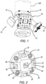
Fig. 1 is a perspective view of a multiple mounting robotic tooling assembly. -
Fig. 2 is a perspective view of a front face of a base. -
Fig. 3 is a perspective view of a rear view of the base. -
Fig. 4 is a perspective view of a stem. -
Fig. 5 is a perspective view of the rear of a tool mount. -
Fig. 6 is a perspective view of the front face of a tool mount. -
Fig. 7 is a partial cross-section view ofFig. 1 . - Example embodiments will now be described more fully with reference to the accompanying drawings.
- Turning to the figures, a multiple mounting robotic tooling assembly is illustrated and designated with the
reference numeral 10. Therobotic tooling assembly 10 includes abase mount 12, stems 14 and tool mounts 16. A tool (not shown) is connected with the tool mounts 16. - The
base mount 12 can have a desired configuration to couple with a robot arm 100 (shown in phantom). Thebase mount 12 is illustrated with an overall cylindrical disk shape. Thebase 12 includes acylindrical disk portion 18 with an extendingcrucifix portion 20, however, various configurations could be used, such as triangular, pentagonal, etc. Thecylindrical disk portion 18 includes a plurality ofapertures 22 to receivefasteners 24 that secure thebase mount 12 with therobotic arm 100. Therear surface 26 of the base mount includes ananti-rotation constraint 28. Theanti-rotation constraint 28 may be a dowel pin or the like that fits into a socket in therobotic arm 100. Also, aboss 30, defining a bore, is positioned on therear surface 26 that matches a locating counterbore on therobotic arm 100. - The
crucifix portion 20 includes a plurality ofreceptacles 32. Eachreceptacle 32 includes a throughbore 34 to receive a bolt to secure arespective stem 14. Thereceptacles 32 include ananti-rotation socket 36. Here thesocket 36 is illustrated as rectangular or squared, however, any desired configuration, triangular, hexagonal or the like could be utilized. Thecrucifix portion 20 includes thereceptacles 32 positioned on a taperedface 38. The tapered faces 38 enable thereceptacles 32 to be spaced with respect to one another to angle the stems 14 toward different location. A desired angle is used for eachtapered face 38 depending on the application. Also, thecrucifix portion 20 includes afront face 40 that also includes areceptacle 32. Thefront face 40 is generally parallel to a face of thecylindrical disk portion 18. Thus, astem 14 that extends from thefront face 40 would be substantially along the axis of thebase 12. - The stems 14 include a
bolt 42 passing through acylinder 44 that forms the stems 14. Thecylinder 44 can have varying sizes depending upon the operation required by the tool. Thecylinder 44 includesshoulders 46 that are precise and firmly seat the stem in thebase mount 12 andtool mount 16.Anti-rotation members 48 are positioned at the ends of thecylinder 44. Theanti-rotation members 48 have a configuration to match thereceptacle socket 36 in thebase mount 12. Here, they are illustrated with an overall rectangular or square configuration with truncated corners. Theanti-rotation members 48 on each end keys into thebase mount 12 and tool mounts 16 to precisely orientate the tool while providing stiffness in the connection against bending from torsion loads of the tool. This also enables the tool to be connected in one of the various orientations. However, the anti-rotation member pattern could have more than four orientations based on the pattern. Thebolt 42 includes ahead 50 with a socket to receive a fastening tool. Theother bolt end 52 is threaded to be received within the thread bore of thetool mount 16. Thus, the head is fit within thebore 34 in arecess portion 54 of thebore 34 in thebase mount 12 as seen inFig. 7 . - The
tool mount 16 includes afront face 60 and arear face 62. Thefront face 60 includes a mounting pattern withscrews 64 and dowel pins 66 to locate a matching tool (not shown). Thus, the pattern enables various types of tools to be connected with thetool mount 16. Therear face 62 of the tool mount includes a threaded bore 68 to receive the threadedbolt 42 from thestem 14. Additionally, thetool mount 16 includes ananti-rotation socket 70 with a cutout, here illustrated as a rectangular or square cutout, to receive theanti-rotation member 48 of thestem 14. Thus, the tool mounts 16 are rigidly secured with the stems 14. Additionally, acylindrical boss 72 projects from therear face 62. Theboss 72 enables theshoulders 46 of the stem to rest or seat upon theboss 72. - Thus, the tool mounts 16, by having the mounting pattern, enables multiple tools to be secured to the
tool mount plate 16 without customization. Additionally, various types oftool mount plates 16 can be utilized to receive tools. Thetool mount plates 16 can be blank for customization or may include patterns to mount tools that normally connect directly to the robot or include a design for popular tools. - To mount the components together, the
bolt 42 is passed through thebore 34 in thebase mount 12. Thecylinder 44 andanti-rotation members 48, on each side of the cylinder, are positioned onto thebolt 42. Oneanti-rotation member 48 mates with theanti-rotation socket 36 of thebase mount 12. Thetool mount 16 is positioned onto the threaded fastener orbolt 42. Thebolt 42 is rotated until theother anti-rotation member 48 seats in thesocket 70 to secure thetool mount 16 with the stem as illustrated inFig. 7 . This is continued to connect the numerous stems 14 andtool mount plates 16 with thebase receptacles 32 as desired. - The foregoing description of the embodiments has been provided for purposes of illustration and description. It is not intended to be exhaustive or to limit the disclosure. Individual elements or features of a particular embodiment are generally not limited to that particular embodiment, but, where applicable, are interchangeable and can be used in a selected embodiment, even if not specifically shown or described. The same may also be varied in many ways. Such variations are not to be regarded as a departure from the disclosure, and all such modifications are intended to be included within the scope of the disclosure.
Claims (14)
- A multiple mounting robotic tooling assembly comprising:a base mount for mounting with a robot, the base mount including a plurality of receptacles, each for receiving a tool stem;one or more tool stems, the one or more tool stems each coupling with one of the plurality of receptacles for mounting a tool to the base;one or more tool mounts, each tool mount couples with one of the one or more stems, the one or more tool mounts receive a tool for conducting an operation.
- The multiple mounting robotic tooling assembly of Claim 1, wherein the receptacles include an anti-rotation mechanism for receiving the stem.
- The multiple mounting robotic tooling assembly of Claim 1, wherein the stems have different lengths.
- The multiple mounting robotic tooling assembly of Claim 2, wherein the stems include a mating anti-rotation member.
- The multiple mounting robotic tooling assembly of Claim 1, wherein the base mount includes an anti-rotation constraint for coupling with the robot.
- The multiple mounting robotic tooling assembly of Claim 4, wherein each stem end includes a mating anti-rotation member.
- The multiple mounting robotic tooling assembly of Claim 1, wherein the tool mounts include an anti-rotation receptacle for receiving the stems.
- A kit for building a multiple mounting robotic tooling assembly comprising:a base mount for mounting with a robot, the base mount including a plurality of receptacles, each for receiving a tool stem;one or more tool stems, the one or more tool stems each coupling with one of the plurality of receptacles for mounting a tool to the base;one or more tool mounts, each tool mount couples with one of the one or more stems, the one or more tool mounts receive a tool for conducting an operation.
- The kit for building a multiple mounting robotic tooling assembly of Claim 8, wherein the receptacles include an anti-rotation mechanism for receiving the stem.
- The kit for building a multiple mounting robotic tooling assembly of Claim 8, wherein the stems have different lengths.
- The kit for building a multiple mounting robotic tooling assembly of Claim 9, wherein the stems include a mating anti-rotation member.
- The kit for building a multiple mounting robotic tooling assembly of Claim 8, wherein the base mount includes an anti-rotation constraint for coupling with a robot.
- The kit for building a multiple mounting robotic tooling assembly of Claim 11, wherein each stem end includes a mating anti-rotation member.
- The kit for building a multiple mounting robotic tooling assembly of Claim 8, wherein the tool mounts include an anti-rotation receptacle for receiving the stems.
Applications Claiming Priority (2)
| Application Number | Priority Date | Filing Date | Title |
|---|---|---|---|
| US202263344606P | 2022-05-22 | 2022-05-22 | |
| US18/311,309 US20230373101A1 (en) | 2022-05-22 | 2023-05-03 | Multiple Mounting Robotic Tool Assembly |
Publications (1)
| Publication Number | Publication Date |
|---|---|
| EP4282603A1 true EP4282603A1 (en) | 2023-11-29 |
Family
ID=86387387
Family Applications (1)
| Application Number | Title | Priority Date | Filing Date |
|---|---|---|---|
| EP23173650.5A Withdrawn EP4282603A1 (en) | 2022-05-22 | 2023-05-16 | Multiple mounting robotic tool assembly |
Country Status (2)
| Country | Link |
|---|---|
| US (1) | US20230373101A1 (en) |
| EP (1) | EP4282603A1 (en) |
Citations (2)
| Publication number | Priority date | Publication date | Assignee | Title |
|---|---|---|---|---|
| DE102016226259A1 (en) * | 2016-12-28 | 2018-06-28 | Kuka Systems Gmbh | SYSTEM FOR PROVIDING AT LEAST ONE WORK PIECE FOR A MEASUREMENT, TESTING OR MACHINING PROCESS |
| US20190299424A1 (en) * | 2018-03-27 | 2019-10-03 | Soft Robotics Inc. | Field- assembled soft gripping for industrial and collaborative robots |
-
2023
- 2023-05-03 US US18/311,309 patent/US20230373101A1/en active Pending
- 2023-05-16 EP EP23173650.5A patent/EP4282603A1/en not_active Withdrawn
Patent Citations (2)
| Publication number | Priority date | Publication date | Assignee | Title |
|---|---|---|---|---|
| DE102016226259A1 (en) * | 2016-12-28 | 2018-06-28 | Kuka Systems Gmbh | SYSTEM FOR PROVIDING AT LEAST ONE WORK PIECE FOR A MEASUREMENT, TESTING OR MACHINING PROCESS |
| US20190299424A1 (en) * | 2018-03-27 | 2019-10-03 | Soft Robotics Inc. | Field- assembled soft gripping for industrial and collaborative robots |
Also Published As
| Publication number | Publication date |
|---|---|
| US20230373101A1 (en) | 2023-11-23 |
Similar Documents
| Publication | Publication Date | Title |
|---|---|---|
| US5481811A (en) | Universal inspection workpiece holder | |
| JP3856339B2 (en) | Cutting tool assembly with replaceable adapter | |
| US8262072B2 (en) | Work piece carrier for exactly positioning a work piece on a chuck and clamping apparatus with a chuck and a work piece carrier | |
| US20100019428A1 (en) | Clamping Fixture | |
| JP6718099B1 (en) | Drill guide jig | |
| US4968012A (en) | Modular workpiece holding apparatus | |
| CN88101857A (en) | Instrument is detachably connected to device on the operating mechanism | |
| US9377385B2 (en) | Rotating dovetail connection for materials testing | |
| US5918868A (en) | Universal modular fixturing systems | |
| CA1260968A (en) | Apparatus for clamping non-rotating work pieces | |
| NZ314755A (en) | Universal socket comprising a plurality of retractable biased pins and a pin positioning mechanism | |
| US20230373101A1 (en) | Multiple Mounting Robotic Tool Assembly | |
| CN101218064B (en) | Clamping device for a tool or a workpiece | |
| US6444941B1 (en) | Tool holding system | |
| US5497980A (en) | Assembly for use in precision machining | |
| US7331104B2 (en) | Device for the assembly of standard elements intended for the creation of precision mechanical structures | |
| EP1566237B1 (en) | Machining jig | |
| CA2408779C (en) | Integration of self-locating feature into detail parts | |
| CN101528392B (en) | Tool holder | |
| US5344166A (en) | Jaw assembly for chucks | |
| EP1749617A1 (en) | Rotating body balancing structure | |
| US5988960A (en) | Holder for plurality of workpieces | |
| US20230364665A1 (en) | Tapered transition pilot | |
| CN118493015A (en) | Continuous processing clamp system and method for metal parts | |
| US5992837A (en) | Workpiece holding assembly |
Legal Events
| Date | Code | Title | Description |
|---|---|---|---|
| PUAI | Public reference made under article 153(3) epc to a published international application that has entered the european phase |
Free format text: ORIGINAL CODE: 0009012 |
|
| STAA | Information on the status of an ep patent application or granted ep patent |
Free format text: STATUS: THE APPLICATION HAS BEEN PUBLISHED |
|
| AK | Designated contracting states |
Kind code of ref document: A1 Designated state(s): AL AT BE BG CH CY CZ DE DK EE ES FI FR GB GR HR HU IE IS IT LI LT LU LV MC ME MK MT NL NO PL PT RO RS SE SI SK SM TR |
|
| STAA | Information on the status of an ep patent application or granted ep patent |
Free format text: STATUS: THE APPLICATION IS DEEMED TO BE WITHDRAWN |
|
| 18D | Application deemed to be withdrawn |
Effective date: 20240530 |