EP4282588A1 - Polishing pad, and polishing method - Google Patents
Polishing pad, and polishing method Download PDFInfo
- Publication number
- EP4282588A1 EP4282588A1 EP22759821.6A EP22759821A EP4282588A1 EP 4282588 A1 EP4282588 A1 EP 4282588A1 EP 22759821 A EP22759821 A EP 22759821A EP 4282588 A1 EP4282588 A1 EP 4282588A1
- Authority
- EP
- European Patent Office
- Prior art keywords
- polishing
- face
- layer
- polishing pad
- polished
- Prior art date
- Legal status (The legal status is an assumption and is not a legal conclusion. Google has not performed a legal analysis and makes no representation as to the accuracy of the status listed.)
- Withdrawn
Links
Images




Classifications
-
- B—PERFORMING OPERATIONS; TRANSPORTING
- B24—GRINDING; POLISHING
- B24B—MACHINES, DEVICES, OR PROCESSES FOR GRINDING OR POLISHING; DRESSING OR CONDITIONING OF ABRADING SURFACES; FEEDING OF GRINDING, POLISHING, OR LAPPING AGENTS
- B24B37/00—Lapping machines or devices; Accessories
- B24B37/11—Lapping tools
- B24B37/20—Lapping pads for working plane surfaces
- B24B37/22—Lapping pads for working plane surfaces characterised by a multi-layered structure
-
- B—PERFORMING OPERATIONS; TRANSPORTING
- B24—GRINDING; POLISHING
- B24B—MACHINES, DEVICES, OR PROCESSES FOR GRINDING OR POLISHING; DRESSING OR CONDITIONING OF ABRADING SURFACES; FEEDING OF GRINDING, POLISHING, OR LAPPING AGENTS
- B24B19/00—Single-purpose machines or devices for particular grinding operations not covered by any other main group
- B24B19/26—Single-purpose machines or devices for particular grinding operations not covered by any other main group for grinding workpieces with arcuate surfaces, e.g. parts of car bodies, bumpers or magnetic recording heads
-
- B—PERFORMING OPERATIONS; TRANSPORTING
- B24—GRINDING; POLISHING
- B24B—MACHINES, DEVICES, OR PROCESSES FOR GRINDING OR POLISHING; DRESSING OR CONDITIONING OF ABRADING SURFACES; FEEDING OF GRINDING, POLISHING, OR LAPPING AGENTS
- B24B27/00—Other grinding machines or devices
- B24B27/0038—Other grinding machines or devices with the grinding tool mounted at the end of a set of bars
-
- B—PERFORMING OPERATIONS; TRANSPORTING
- B24—GRINDING; POLISHING
- B24B—MACHINES, DEVICES, OR PROCESSES FOR GRINDING OR POLISHING; DRESSING OR CONDITIONING OF ABRADING SURFACES; FEEDING OF GRINDING, POLISHING, OR LAPPING AGENTS
- B24B37/00—Lapping machines or devices; Accessories
- B24B37/11—Lapping tools
- B24B37/20—Lapping pads for working plane surfaces
- B24B37/24—Lapping pads for working plane surfaces characterised by the composition or properties of the pad materials
-
- B—PERFORMING OPERATIONS; TRANSPORTING
- B24—GRINDING; POLISHING
- B24B—MACHINES, DEVICES, OR PROCESSES FOR GRINDING OR POLISHING; DRESSING OR CONDITIONING OF ABRADING SURFACES; FEEDING OF GRINDING, POLISHING, OR LAPPING AGENTS
- B24B37/00—Lapping machines or devices; Accessories
- B24B37/11—Lapping tools
- B24B37/20—Lapping pads for working plane surfaces
- B24B37/26—Lapping pads for working plane surfaces characterised by the shape of the lapping pad surface, e.g. grooved
-
- B—PERFORMING OPERATIONS; TRANSPORTING
- B24—GRINDING; POLISHING
- B24B—MACHINES, DEVICES, OR PROCESSES FOR GRINDING OR POLISHING; DRESSING OR CONDITIONING OF ABRADING SURFACES; FEEDING OF GRINDING, POLISHING, OR LAPPING AGENTS
- B24B57/00—Devices for feeding, applying, grading or recovering grinding, polishing or lapping agents
- B24B57/02—Devices for feeding, applying, grading or recovering grinding, polishing or lapping agents for feeding of fluid, sprayed, pulverised, or liquefied grinding, polishing or lapping agents
Definitions
- the present invention relates to a polishing pad and a polishing method using the polishing pad.
- Buffing has been known as a processing method to smooth a surface to be polished, such as a coated body face of automobiles (for example, PTL 1). Such a surface to be polished includes a curved face.
- the buffing is a polishing method by rotating a buffing wheel (buff) that is made from a fabric or a similar material and has a periphery (surface) with various abrasives or the like.
- the buffing can fail to remove waviness on a surface to be polished and is difficult to achieve a beautiful surface finish.
- PTL 2 discloses a polishing pad having a structure allowing a polishing face that is to come into contact with a surface to be polished at the time of polishing to follow a curved face portion of the surface to be polished.
- the polishing pad has a two-layer structure including a hard resin layer having a polishing face and a soft resin layer supporting the hard resin layer.
- the soft resin layer is disclosed to have a hardness of 30 degrees or less in terms of E hardness in accordance with JIS K 6253.
- PTL 3 discloses a polishing pad with a support layer.
- the polishing pad includes a polishing layer having a polishing face and a support layer fixed to a face opposite to the polishing face of the polishing layer.
- the support layer is softer than the polishing layer.
- the support layer is disclosed to have a hardness of 30 or more and 90 or less in terms of F hardness (determined with an "ASKER Durometer Type F" manufactured by KOBUNSHI KEIKI CO.,LTD.).
- PTL 4 discloses a polishing pad for polishing a surface to be polished by using a polishing slurry containing abrasives in order to achieve a better surface finish, and grooves are formed on a polishing face.
- the polishing face is formed from a polyurethane foam or a nonwoven fabric. By forming the grooves, the polishing face easily follows a curved face of a polishing target, and the polishing efficiency is improved.
- polishing pads disclosed in PTLs 2 and 3 have room for improvement in the performance of following a curved face portion of a surface to be polished.
- the present invention is intended to provide a polishing pad capable of improving the performance of following a curved face portion of a surface to be polished.
- an aspect of a polishing pad of the present invention includes a polishing layer having a polishing face and a support layer that is softer than the polishing layer and is fixed to a face opposite to the polishing face of the polishing layer, and the support layer has a hardness of not less than 30 and less than 70 in terms of F hardness.
- the performance of following a curved face portion of a surface to be polished should be improved.
- a polishing pad 1 in the embodiment includes a disk-shaped polishing layer 2 having a polishing face 21 and a cylindrical support layer 3.
- the polishing face 21 is the face to be pressed against a surface to be polished of a polishing target when the polishing target is polished.
- the support layer 3 is fixed to a face 22 opposite to the polishing face 21 of the polishing layer 2 with an adhesive or a double-sided adhesive tape.
- the polishing layer 2 is a suede or a nonwoven fabric and has a thickness of 0.5 mm or more and 5.0 mm or less.
- the polishing layer 2 has a hardness of 40 or more and 90 or less in terms of hardness (C hardness) determined immediately after close contact with a pressure foot in the test method defined by "Spring hardness test, type C test method" in appendix 2 in JIS K7312: 1996.
- the edge 211 on the polishing face 21 is chamfered by cutting.
- the polishing layer 2 may not be chamfered.
- the support layer 3 is made from a polyurethane foam.
- the support layer 3 has a hardness of not less than 30 and less than 70 in terms of F hardness (determined with an "ASKER Durometer Type F" manufactured by KOBUNSHI KEIKI CO.,LTD. and specifically determinable by, for example, a method in examples).
- the support layer 3 has a density of 20 kg/m 3 or more and 60 kg/m 3 or less.
- the support layer 3 has a thickness of 2.0 mm or more and 50 mm or less.
- An F hardness of 90 corresponds to a C hardness of less than 10, and thus the support layer 3 is softer than the polishing layer 2.
- the surface to be polished is polished.
- the surface to be polished includes a curved face, a flat face, or both of them.
- the curved face may be a concave curved face, a convex curved face, or both of them.
- a concave curved face and a convex curved face are not particularly differentiated, such a curved face is simply called a curved face.
- the surface to be polished is not specifically limited and may be, for example, a coating face of a synthetic resin, a metal face, a silicon wafer face, a glass face, a sapphire face, a polycrystalline face such as a ceramic face, a synthetic resin face other than the coating face, or a combination of them.
- the polishing face 10 When the polishing face 10 is pressed against a concave curved face or a convex curved face of a surface to be polished, the soft support layer 3 easily deforms along the surface to be polished. Accordingly, the hard polishing layer 2 fixed to the support layer 3 also deforms as with the support layer 3. As a result, the polishing face 21 easily follows the concave curved face or the convex curved face of the surface to be polished. In other words, the polishing pad 1 has a higher performance of following curved face portions of a surface to be polished. As the polishing pad 1 has a higher following performance, the polishing face 21 comes into contact with a surface to be polished in a larger area when the polishing pad is pressed against a curved face portion of the surface to be polished.
- the support layer 3 has a hardness of not less than 30 and less than 70 in terms of F hardness.
- the polishing pad 1 in the embodiment has a higher performance of following a curved face portion of a surface to be polished.
- the support layer 3 has a density of 20 kg/m 3 or more and 60 kg/m 3 or less. The polishing pad accordingly has a much higher following performance.
- the polishing layer 2 has a hardness of 40 or more and 90 or less in terms of C hardness. Hence, waviness on a surface to be polished can be suitably removed.
- polishing scratches can be suppressed on a surface to be polished.
- Examples of the polishing target having a surface to be polished including concave curved faces and convex curved faces include various members (such as a vehicle body and a synthetic resin member) constituting vehicles and the like (such as an automobile, a rail car, an aircraft, a bicycle, and a ship) and construction materials.
- the polishing layer preferably has a thickness of 0.5 mm or more and 5.0 mm or less. Within such a range, the polishing layer easily removes waviness, and the polishing layer easily deforms as with the support layer.
- the polishing face preferably has a diameter of 10 mm or more and 200 mm or less. Within such a range, the polishing face easily follows a curved surface to be polished. In addition, when a polishing composition is supplied from the outer edge of the polishing face during polishing, the polishing composition can spread from the outer edge to the center portion on the polishing face for a shorter time period. The polishing face is not too small, and this can suppress the reduction in operating efficiency.
- the surface to be polished may be any surface, but the polishing pad of the present invention has a high performance of following a curved face portion of a surface to be polished and thus is advantageously used to polish a surface to be polished including a curved face.
- the curved face may be a concave curved face or a convex curved face.
- the surface to be polished is preferably a coating face of a synthetic resin or a synthetic resin face other than the coating face. When used to polish a coating face of a synthetic resin or a synthetic resin face other than the coating face, the polishing pad can suitably achieve the effect of removing waviness.
- the concave curved face When the surface to be polished includes a concave curved face, the concave curved face preferably has a curvature radius of 10 mm or more, more preferably 35 mm or more, and even more preferably 50 mm or more.
- a concave curved face having a larger curvature radius is likely to be in contact with the polishing pad in a larger area.
- adjusting the angle with the polishing pad is likely to help polishing as compared with the concave curved face, and thus the convex curved face may have any curvature radius unlike the concave curved face.
- the ratio of the diameter of the polishing face to the curvature radius of the curved face, or "the diameter of the polishing face/the curvature radius of the curved face” is preferably 1.1 or less, more preferably 1.0 or less, even more preferably 0.75 or less, further preferably 0.6 or less, still more preferably 0.5 or less, still further preferably 0.3 or less, and particularly preferably 0.14 or less.
- a smaller ratio of "the diameter of the polishing face/the curvature radius of the curved face" is likely to improve the following performance.
- the polishing layer preferably has a C hardness of 40 or more and 90 or less and is, for example, produced from polyurethane or the like other than the suede type or the nonwoven fabric type.
- the polishing layer more preferably has a C hardness of 50 or more and 80 or less.
- the polishing layer preferably has a sparse-dense structure (the proportion of the sparse portion is 50% or more and 96% or less).
- the material of the support layer include, in addition to a polyurethane foam, a polyethylene foam, a rubber foam, a melamine foam, and a silicone foam.
- the support layer preferably has a hardness of not less than 30 and less than 70 and more preferably 40 or more and 60 or less in terms of F hardness.
- An ASKER Durometer Type F is a durometer having a large indenter and a pressure foot so as to give an accurate reading in hardness measurement of a particularly soft sample, and the pressure needle has a cylindrical shape having a height of 2.54 mm and a diameter of 25.2 mm.
- the support layer preferably has a density of 20 kg/m 3 or more and 60 kg/m 3 or less and more preferably 40 kg/m 3 or more and 60 kg/m 3 .
- the support layer preferably has an elongation of 70% or more and 300% or less, more preferably 70% or more and 150% or less, and even more preferably 75% or more and 110% or less.
- Suede type For example, a nonwoven fabric or textile fabric formed from synthetic fibers, a synthetic rubber, and the like or a polyester film is used as the base material. Onto the top face of the base material, a polyurethane solution is applied, and the polyurethane solution is solidified by wet solidification method, giving an outer surface layer of a porous layer having continuous pores. As needed, the surface of the outer surface layer is ground and removed.
- Nonwoven fabric type For example, a needle-punched nonwoven fabric formed from polyester short fibers is impregnated with a polyurethane elastomer solution. The impregnated nonwoven fabric is immersed in water to undergo wet solidification. The solidified nonwoven fabric is washed with water and dried. Each surface of the dried fabric is ground.
- a needle-punched nonwoven fabric formed from polyester short fibers is impregnated with a thermosetting urethane resin solution. The impregnated nonwoven fabric is dried to fix the thermosetting urethane resin to the nonwoven fabric. Each surface is subjected to sanding to remove unevenness.
- a polishing composition containing abrasives is supplied to the surface to be polished of an object to be polished, and the polishing pad is moved while the polishing face is pressed against the surface to be polished, polishing the surface to be polished.
- the polishing pad is, for example, attached to the tip of a polishing apparatus.
- the polishing apparatus rotates the polishing pad around the axis intersecting the polishing face, and the polishing pad sweeps a surface to be polished.
- the polishing apparatus may be a hand polisher that manually sweeps a surface or may be an automatic polishing machine (polishing robot) that automatically sweeps a surface.
- the surface to be polished is, for example, preferably larger than the polishing face of the polishing layer in the polishing pad and preferably includes a curved face.
- the polishing method using the polishing pad in an embodiment of the present invention can be suitably used to polish a surface to be polished larger than the polishing face.
- the polishing pad in an embodiment of the present invention and the polishing method using the polishing pad are preferably applied to rough polishing.
- the rough polishing is polishing before the final polishing step (finish polishing).
- Examples of the abrasives contained in the polishing composition (such as a slurry and a compound) used in a polishing method using the polishing pad in an embodiment of the present invention include abrasives selected from particles of an oxide of silicon or a metal element, such as silica, alumina, ceria, titania, zirconia, iron oxide, and manganese oxide, particles of a carbide, particles of a nitride, organic particles of a thermoplastic resin, and organic-inorganic composite particles.
- abrasives selected from particles of an oxide of silicon or a metal element, such as silica, alumina, ceria, titania, zirconia, iron oxide, and manganese oxide, particles of a carbide, particles of a nitride, organic particles of a thermoplastic resin, and organic-inorganic composite particles.
- an alumina slurry containing alumina particles is preferably used because the slurry can achieve a high polishing removal rate and is easily available.
- the alumina includes aluminas different in crystal morphology, such as ⁇ -alumina, ⁇ -alumina, ⁇ -alumina, and ⁇ -alumina, and also includes an aluminum compound called hydrated alumina. From the viewpoint of the polishing removal rate, a slurry containing particles mainly including ⁇ -alumina as the abrasives is more preferably used.
- the abrasives preferably have an average particle diameter of 0.01 ⁇ m or more and 10.0 ⁇ m or less and more preferably 0.3 ⁇ m or more and 5.0 ⁇ m or less. Abrasives having a larger average particle diameter give a higher polishing removal rate. When the average particle diameter is within the above range, the polishing removal rate is easily increased to a particularly suitable level in practice. Abrasives having a smaller average particle diameter have a higher dispersion stability and suppress scratches on a polishing face.
- the average particle diameter is within the above range, the dispersion stability of the abrasives and the surface accuracy on a polishing face are easily improved to a particularly suitable level in practice.
- the average particle diameter can be determined, for example, with a particle diameter distribution analyzer, LA-950, manufactured by HORIBA, Ltd.
- the content of abrasives in the polishing composition is preferably 0.1% by mass or more and 50% by mass or less, more preferably 0.2% by mass or more and 25% by mass or less, and even more preferably 0.5% by mass or more and 20% by mass or less.
- the polishing removal rate increases.
- the polishing removal rate is easily increased to a particularly suitable level in practice while the cost is suppressed.
- surface defects on the surface of a polished object can be further suppressed.
- the polishing composition may appropriately contain, in addition to abrasives and dispersants therefor, additional components such as a lubricant, an organic solvent, a surfactant, and a thickener, as needed.
- the lubricant may be a synthetic oil, a mineral oil, a vegetable oil and fat, or a combination of them.
- the organic solvent may be a hydrocarbon solvent as well as an alcohol, an ether, a glycol, or glycerol.
- the surfactant may be what is called an anionic surfactant, a cationic surfactant, a nonionic surfactant, or an amphoteric surfactant.
- the thickener may be a synthetic thickener, a cellulose thickener, or a natural thickener.
- polishing pad having a polishing face with grooves pores or grooves on the polishing face of the polishing pad clog with a particulate substance during polishing, and consequently, the polishing efficiency may decrease as polishing is performed for a long time period. Hence, frequent brushing is required to prevent clogging during a polishing process. This requires more labor and may extend the processing time.
- a polishing pad capable of suppressing the reduction in polishing efficiency over time and a polishing method using the polishing pad are demanded.
- the reduction in polishing efficiency over time can be suppressed by performing polishing with a polishing pad including a polishing layer having a polishing face and including a support layer that is softer than the polishing layer and is fixed to a face opposite to the polishing face of the polishing layer.
- the support layer has a hardness of not less than 30 and less than 70 in terms of F hardness, and the polishing layer has grooves on the polishing face.
- the ratio (S m /S k ) of the total area S m (cm 2 ) of the grooves to the total area S k (cm 2 ) of the polishing face is 0.30 or more and 0.80 or less, and the ratio (V m /S k ) of the total volume V m (cm 3 ) of the grooves to the total area S k (cm 2 ) of the polishing face is 0.07 or more.
- the polishing pad in the embodiment is attached to a polishing robot, a manual polisher, or the like and is used to polish a polishing object.
- An example polishing pad applied to a polishing robot will next be described.
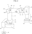
- FIG. 2 illustrates the configuration of a 6-axis articulated robot as an example of the polishing robot.
- the polishing robot usable in the present invention is not limited to 6-axis articulated robots.
- a polishing robot 11 has a base 12, a lower arm 14, an upper arm 16, and a wrist 18.
- an S-axis motor 13S that has a rotation axis in the perpendicular direction to the base 12 and is configured to revolve the upper part from the base 12
- an L-axis motor 13L that has a rotation axis in a direction orthogonal to the rotation axis of the S-axis motor 13S and is configured to tilt the lower arm 14 forward or backward relative to the base 12 are provided.
- a U-axis motor 15U that has a rotation axis in a direction parallel with the rotation axis of the L-axis motor 13L and is configured to revolve the upper arm 16 relative to the lower arm 14 and an R-axis motor 15R that has a rotation axis in a direction perpendicular to the rotation axis of the U-axis motor 15U and is configured to rotate the upper arm 16 relative to the lower arm 14 are provided.
- a B-axis motor 17B that has a rotation axis in a direction orthogonal to the rotation axis of the R-axis motor 15R and is configured to revolve the wrist 18 relative to the upper arm 16 is provided.
- a T-axis motor 17T that has a rotation axis in a direction orthogonal to the rotation axis of the B-axis motor 17B and is configured to rotate the part beyond the wrist 18 is provided.
- the polishing robot 11 has these six rotation axis-motors, and thus the wrist 18 at the tip can trace any surface with three-dimensional curved faces.
- a three-dimensional curved face means a face that is not consisting of only flat faces (a face at least partly including a non-flat face).
- the rotation axes of the respective motors are called an S-axis 13Sa, an L-axis 13La, a U-axis 15Ua, an R-axis 15Ra, a B-axis 17Ba, and a T-axis 17Ta.
- a pressure controller 20 is provided through the T-axis motor 17T, and to the pressure controller 20, a polisher 30 is provided.
- the pressure controller 20 has a box shape and includes a mechanism of sensing pressure and a mechanism of directing pressurizing force for controlling pressure.
- the pressure applying direction from the pressure controller 20 is a pressure controller central axis 20c.
- the pressure controller central axis 20c is perpendicular to the T-axis 17Ta of the wrist 18.
- a force sensor or a load cell may be used as the pressure sensing mechanism included in the pressure controller 20.
- the pressure sensing mechanism may be integrated with a robot main body, for example, as in a collaborative robot.
- the pressurizing force directing mechanism included in the pressure controller 20 may be, for example, pressurization by air or pressurization by a servomotor.
- the pressurizing force directing mechanism may be integrated with a robot main body, for example, as in a collaborative robot.
- the control command value of pressurizing force may be commanded in terms of a force value (Newton; N).
- the pressure controller 20 may be configured to control the processing pressure at 1,000 N/m 2 or more and 6,000 N/m 2 or less and is preferably configured to control the processing pressure at 2,500 N/m 2 or more and 6,000 N/m 2 or less. Polishing at a processing pressure within the above range enables polishing with efficient orange peel removability on an object to be polished described later. At a processing pressure of less than 1,000 N/m 2 , the efficiency of orange peel removal on an object to be polished deteriorates, whereas at a processing pressure of more than 6,000 N/m 2 , a provided polisher 30 may break.
- the variation in processing pressure relative to a command value controlled by the pressure controller 20 is preferably within ⁇ 20% and more preferably within ⁇ 10%. In such a range, the in-plane variation in the polishing efficiency on an object to be polished described later is suppressed, and uniform polishing can be performed as compared with hand polishing.
- the polisher 30 is an electric single action polisher typically used manually and is placed such that the rotation axis of the polisher 30 is coincident or parallel with the pressure controller central axis 20c as much as possible.
- the polisher 30 pertaining to the present embodiment may be provided, for example, in a bipolar manner to the pressure controller 20.
- the polisher 30 pertaining to the present embodiment is preferably a single-rotation electric polisher, and may be driven by, for example, electricity, air, or gears, or may be, for example, a single rotation type or a double-action rotation type.
- a polishing pad attachment part 40 of the polisher 30 may be formed from any material that is harder than the material of a polishing pad to sufficiently transmit a processing pressure to the polishing pad, and examples of the material include a resin, a metal, a ceramic, a fiber-reinforced resin, and a composite material.
- the fiber-reinforced resin include a carbon fiber-reinforced resin and a glass fiber-reinforced resin.
- the resin used in the fiber-reinforced resin may be any type, and examples include an epoxy resin.
- Examples of the composite material include a composite material of two or more types of materials, such as a metal intentionally containing inorganic particles.
- a robot controller 60 is connected to drive units of the respective axis motors of the polishing robot 11.
- the robot controller is also connected to the pressure controller 20, the polisher 30, a pad cleaner 65 such as a pad dresser, and other units not illustrated in the drawings, such as a polishing material supply unit and a pad exchanger.
- the robot controller 60 controls the drive of the pressure controller 20 and the polisher 30 such that the pressure controller 20 senses a constant pressure.
- a memory (not illustrated) of the robot controller 60 stores space data of a face to be polished on a polishing target. From the polishing material supply unit, a polishing composition is supplied between a polishing pad and an object to be polished, and the object to be polished is polished.
- steps for polishing can be automatically performed.
- steps for polishing can be automatically performed.
- the pad cleaner 65 has a brush, and brushing the polishing face of a polishing pad can remove members or the like generated by polishing and clogged in grooves formed on the polishing face or in a nonwoven fabric or the like of the polishing face.
- the polishing pad pertaining to the present embodiment includes a layer having a polishing face.
- the layer (polishing layer) having the polishing face may have a sparse-dense structure, and the proportion of the sparse portion may be 52% or more and 96% or less.
- the polishing face may include a sheet material having an A hardness of 70 or more determined by a method in accordance with JIS K 6253.
- the polishing pad pertaining to the present embodiment includes a layer having a polishing face.
- the layer having the polishing face include, for example, a sheet material of a fiber aggregate.
- the polishing face has a sparse portion at a proportion of 52% or more and 96% or less and has an A hardness of 70 or more determined by a method in accordance with JIS K 6253.
- the sparse portion is voids (pores) among fibers.
- the layer having a polishing face may include a nonwoven fabric pad or a sheet material containing resin fibers.
- the nonwoven fabric pad may include only fibers or include fibers impregnated with a resin.
- the layer having a polishing face contains, for example, fibers of a synthetic resin
- the synthetic resin may include a material containing a nylon resin, a polyester resin, a polyurethane resin, an epoxy resin, an aramid resin, a polyimide resin, or a polyethylene resin.
- the polishing pad pertaining to the present embodiment further includes, on a face opposite to the polishing face of the layer having the polishing face, a support layer supporting the layer having the polishing face.
- the support layer supporting the layer having the polishing face may include a resin elastic body.
- the support layer may have a multi-layer structure including two or more layers.
- the layer supporting the layer having the polishing face may have a lower hardness A determined by a method in accordance with JIS K 6253 than the layer having the polishing face.
- the polishing pad pertaining to the present embodiment is a polishing pad having a two-layer structure including a hard layer constituting the polishing face and a soft layer supporting the hard layer, and thus when the polishing face is pressed against a curved face of a resin coated face, the soft layer is strained along the curved face, and accordingly, the hard layer bends. Hence, the polishing face is likely to follow the curved face of the resin coated face.
- a constitution example of a polishing pad having a two-layer structure including a hard layer constituting a polishing face and a soft layer supporting the hard layer will next be described.
- a hard layer constituting a polishing face is simply called a "hard layer”
- a soft layer supporting the hard layer is simply called a "soft layer”.
- a "hard layer” and a “soft layer” indicate relative features of the layers.
- the hard means that the hardness of a "layer constituting a polishing face" as one layer is higher than the hardness of a "layer supporting a layer having a polishing face” as the other layer.
- the soft means that the hardness of a "layer supporting a layer having a polishing face” as the other layer is lower than the hardness of a "layer constituting a polishing face” as one layer.
- FIG. 3A is a perspective view illustrating the polishing face side of a polishing pad 110 in the embodiment; and FIG. 3B is a plan view of the polishing pad 110 viewed from the polishing face side.
- FIG. 3C is a sectional view taken along line A-A in the figures. In FIG. 3A , the grooves on the polishing face are not illustrated.
- the polishing pad 110 in the embodiment has a two-layer structure including a hard layer (polishing layer) 140 and a soft layer (support layer) 150.
- the hard layer 140 has a polishing face 130 of the polishing pad 110.
- the polishing face 130 is a face to face an object to be polished during polishing and includes sparse portions and dense portions of the sparse-dense structure described later as well as portions with grooves.
- at least the hard layer 140 has a circular shape when viewed from the hard layer 140 side.
- the hard layer 140 has a sparse-dense structure, may include a sheet material having a sparse portion area ratio of 52% or more and 96% or less on the polishing face 130, preferably includes a sheet material having a sparse portion area ratio of 54% or more and 96% or less, and more preferably includes a sheet material having a sparse portion area ratio of 60% or more and 96% or less.
- the interface between the polishing face of the polishing pad and the surface to be polished of an object to be polished has a larger holding power of a polishing composition described later, and a sufficient polishing removal rate can be achieved.
- the interface between the polishing face of a polishing pad and the surface to be polished of an object to be polished may be called a polishing interface.
- the polishing interface is likely to have a smaller holding power of a polishing composition, and the polishing efficiency is likely to deteriorate.
- grooves 131 are formed on the polishing face 130 of the hard layer 140.
- the polishing contact face (a portion of the polishing face 130 without grooves 131) may have a sparse portion area ratio of 52% or more and 96% or less.
- the sparse portion area ratio may be adjusted by any method.
- the sparse portion area ratio may be adjusted by the thickness of fibers, the content of fibers, the amount of a resin when a nonwoven fabric is impregnated with the resin, patterning on the surface, or the like;
- the sparse portion area ratio may be adjusted by the diameter of structure materials, the intervals of structure, lamination conditions, or the like;
- the sparse portion area ratio may be adjusted by the type of a foaming agent, the amount of a foaming agent, or the like; or for a suede formed by a wet film forming method, the sparse portion area ratio may be adjusted by film forming conditions or buffing conditions.
- the sparse portion area ratio of a hard layer 140 can be determined, for example, by image analysis of an image of the surface of a polishing pad observed under a microscope. Specifically, the surface of a polishing pad is observed under a shape analysis laser microscope (for example, VK-X200 by KEYENCE CORPORATION), and any 10 regions each having a viewing angle of 1.4 mm ⁇ 1.4 mm and a height direction of 0.1 mm are recorded at a magnification of 200 (10 ⁇ objective, 20 ⁇ eyepiece). Each recorded image is converted into a monochrome image and automatically binarized by using an image analysis software (for example, WinROOF 2018 manufactured by MITANI CORPORATION), and the ratio of the white area to the whole area is calculated.
- image analysis software for example, WinROOF 2018 manufactured by MITANI CORPORATION
- the " sparse portion” is a portion in which fibers or the like constituting a polishing pad 110 are not observed in a range within 0.1 mm in depth from the outermost surface of the polishing pad 110.
- a layer having the polishing face 130 may have a void area ratio of 52% or more and 96% or less in a range within 0.1 mm in depth from the outermost surface.
- the "area” means an area when a layer having the polishing face 130 is viewed in the thickness direction.
- the hard layer 140 may have a hardness of 70 or more and preferably 80 or more in terms of A hardness determined by a method in accordance with JIS K 6253. Within such a range, polishing a curved face of a resin coated face with the polishing pad 110 is unlikely to be profile polishing that follows even a fine uneven shape of a resin coated face and can remove the surface waviness on a resin coated face. If a hard layer 140 has an A hardness of less than 70, the waviness removability of the hard layer 140 is reduced, and fine surface finish is unlikely to be achieved.
- the maximum A hardness determined by a method in accordance with JIS K 6253 is 100.
- the A hardness of a nonwoven fabric sheet can be adjusted by the material of fibers, the thickness of fibers, the content of fibers, the amount of an impregnated resin, the hardness of an impregnated resin, or the like.
- the A hardness of a hard layer 140 can be determined by a method in accordance with JIS K 6253.
- a durometer Type AL manufactured by ASKER
- CL-150L manufactured by ASKER constant loader
- the durometer Type AL is brought into contact with the test piece without impact.
- the mass applied to the pressure foot is set at 1 kg, and a numerical value of the durometer Type AL is read 15 seconds after the contact. The measurement is performed at five points at intervals of 3 mm, and the minimum value is adopted.
- the material of the hard layer 140 is not specifically limited and may be a material having a sparse portion area ratio of 52% or more and 96% or less on the polishing face 130 and having an A hardness of 70 or more.
- Examples of the hard layer 140 include various layers different in material, such as a polyurethane type, a polyurethane foam type, a nonwoven fabric type, and a suede type, layers different in physical properties such as hardness and thickness, a layer containing abrasives, and a layer containing no abrasives, and these layers may be used without any limitation.
- the material of the hard layer 140 may be, for example, a nonwoven fabric and is preferably a sheet material containing resin fibers.
- the dense portion of the polishing face may include a material containing fibers and a resin.
- the material of the hard layer 140 may be a material containing a synthetic resin.
- the synthetic resin contained in the hard layer 140 may include, for example, a material containing at least one of a nylon resin, a polyester resin, a polyurethane resin, an epoxy resin, an aramid resin, a polyimide resin, and a polyethylene resin. Using such a material can suppress deep scratches on the surface to be polished of an object to be polished.
- the resin fibers in the hard layer 140 a nylon resin, a polyester resin, a polyurethane resin, and a polyethylene resin are preferred, and a nylon resin and a polyester resin are more preferred.
- the synthetic resin in the hard layer 140 may be cured by a curing agent or may be thermally cured.
- the resin fibers in the hard layer 140 may have any thickness, but the thickness is preferably 1 denier or more and is preferably 10 denier or less.
- the resin fibers may have a uniform thickness, or two or more types of resin fibers having different thicknesses may be mixed.
- the hard layer 140 may have any thickness, but the thickness is preferably 0.05 cm or more. The thickness is preferably 0.5 cm or less.
- a hard layer 140 having a thickness within such a range is used to press the polishing face 130 against a curved face of a resin coated face, the hard layer 140 easily bends along the curved face of the resin coated face, and the polishing face 130 is likely to have a higher performance of following the curved face of the object to be polished. Hence, waviness components of the surface shape on an object to be polished can be removed.
- the whole region in the diameter direction of the polishing face 130 may easily come into contact with a curved face, and the polishing efficiency is likely to be improved.
- the soft layer 150 is a layer so as to support the hard layer 140 on the face opposite to the polishing face 130 of the hard layer 140.
- the soft layer 150 may be an elastic body and is preferably a resin elastic body.
- the soft layer 150 has a hardness of not less than 30 and less than 70 and preferably 40 or more and 60 or less in terms of F hardness (hardness determined with an "ASKER Durometer Type F" manufactured by KOBUNSHI KEIKI CO.,LTD.).
- the ASKER Durometer Type F is a durometer having a large indenter and a pressure foot so as to give an accurate reading in hardness measurement of a particularly soft sample, and the pressure needle has a cylindrical shape having a height of 2.54 mm and a diameter of 25.2 mm.
- the soft layer 150 may have any thickness, but the thickness is preferably 0.50 cm or more.
- the soft layer 150 preferably has a thickness of 5.0 cm or less. Within such a range, when the polishing face 130 is pressed against a curved face of a resin coated face, the strain amount of the soft layer 150 and the bending amount of the hard layer 140 can be ensured.
- the material of the soft layer 150 is not specifically limited, and a material having the above hardness can be used.
- the material of the soft layer 150 may be, for example, a resin foam such as a polyurethane foam and a polyethylene foam.
- the polishing face 130 of the polishing pad 110 preferably has a diameter of 10 mm or more and 200 mm or less (condition a).
- the polishing pad 110 preferably has a larger diameter than the diameter of a polishing pad attachment part 40 because the pressure distribution is more uniform during polishing an object to be polished, and handleability is improved during polishing.
- the ratio of the diameter of the polishing pad 110 to the diameter of the polishing pad attachment part 40 is preferably 1.04-fold or more and 2-fold or less, more preferably 1.04-fold or more and 1.6-fold or less, and even more preferably 1.1-fold or more and 1.3-fold or less.
- the polishing pad 110 may be fixed to the polishing pad attachment part 40 of a polisher 30 by any method, and examples of the method include fixation methods using a double-sided adhesive tape, an adhesive, a hook and loop fastener, or the like.
- the sectional shape of a portion to come into contact with the polishing pad attachment part 40 of a polisher 30 is not specifically limited, and examples of the shape include a straight line shape, a curved line shape, and a combination shape of them.
- the outer peripheral shape of a portion to come into contact with the polishing pad attachment part 40 of a polisher 30 is not specifically limited, and examples of the shape include a circular shape, a polygonal shape, a petal shape, and a star shape.
- the surface of a portion to come into contact with the polishing pad attachment part 40 of a polisher 30 may be subjected to processing including grooving, punching, embossing, and other processing.
- grooves 131 are formed on the polishing face 130.
- the grooves 131 are not, for example, cavities (sparse portions) formed by unevenness (pores) of a nonwoven fabric itself, but are grooves formed by separately providing recesses in a hard layer or in a nonwoven fabric itself as illustrated in FIG. 3C .
- a polishing composition easily spreads on the entire area of the polishing face, and the polishing face easily follows an object to be polished.
- the shape of the groove 131 preferably satisfies the following conditions 1 to 5.
- the groove 131 has a width of 0.5 mm or more and 5.0 mm or less.
- the groove 131 has a depth of 0.5 mm or more and 2.5 mm or less.
- Condition 3 The quotient (groove area ratio) calculated by dividing the total area of the grooves 131 (or the sum of the areas of all the grooves 131) by the total area of the polishing face 130 (or the area of the entire polishing face 130), or the ratio (S m /S k ) of the total area S m (cm 2 ) of the grooves 131 to the total area S k (cm 2 ) of the polishing face 130 is 0.30 or more and 0.80 or less.
- a polishing face 130 is a face to face a polishing target during polishing, and the "total area of a polishing face 130" includes the areas of the sparse portion and the dense portion of a sparse-dense structure and the area of grooves 131.
- the "polishing face total area” or the “total area of a polishing face” has the same meaning as the "total area of a polishing face 130".
- Condition 4 The quotient (groove volume/polishing face total area) calculated by dividing the total volume of grooves 131 (or the sum of the volumes of all the grooves 131) by the total area of the polishing face 130, or the ratio (V m /S k ) of the total volume V m (cm 3 ) of the grooves to the total area S k (cm 2 ) of the polishing face is 0.07 or more.
- Each continuous groove 131 at least partially reaches the outer edge of the polishing face 130, and each groove 131 is open at the outer edge.
- the groove width is preferably 4.0 mm or less and more preferably 3.0 mm or less from the viewpoint of improving the polishing efficiency.
- the pitch as the distance between grooves can be set depending on the groove width and/or the diameter of the polishing face.
- the difference between the pitch and the groove width is preferably 1.0 mm or more, more preferably 1.5 mm or more, and even more preferably 2.0 mm or more from the viewpoint of the strength of the polishing pad.
- the release of projections can be prevented during polishing due to an excessively large groove width relative to the pitch and excessively thin projections (polishing contact face) between grooves.
- the groove depth (the difference from the pad thickness as the thickness of the hard layer (polishing layer), "pad thickness (mm) - groove depth (mm)" > 0) is preferably 0.5 mm or more and more preferably 1.0 mm or more from the viewpoint of the strength of the polishing pad. Within the range, the release of the hard layer due to an excessively large groove depth can be prevented.
- the groove area ratio is preferably 0.35 or more, more preferably 0.40 or more, and even more preferably 0.50 or more from the viewpoint of suppressing the reduction in polishing efficiency.
- the groove area ratio is preferably 0.70 or less and more preferably 0.60 or less from the viewpoint of the strength or the projection area effective for polishing.
- the groove volume/the polishing face total area is preferably 0.10 or more, more preferably 0.13 or more, and even more preferably 0.15 or more from the viewpoint of suppressing the reduction in polishing efficiency.
- the groove volume/the polishing face total area may be, for example, 0.16 or less to suppress the reduction in strength of the polishing pad due to an excessively large groove volume.
- the polishing pad 110 is required to be refreshed by brushing the polishing face 130 of the polishing pad 110 with a pad cleaner 65 because the polishing efficiency cannot be maintained when the grooves 131 or the projections on the polishing face 130 clog.
- brushing is required, for example, about every 5 minutes in order to maintain the polishing efficiency.
- the shape of the groove 131 is a particular shape to decrease the reduction rate of the polishing efficiency, reducing the brushing frequency.
- the groove shape such a shape as to further decreases the reduction rate of the polishing efficiency even when the pad is continuously used without brushing is selected, and the groove shape is a shape satisfying the condition a and the conditions 1 to 5.
- the groove 131 partially reaches the outer edge of the polishing face 130, and the groove 131 is open. This structure prevents the grooves 131 from retaining a polishing composition more than needed and discharges unnecessary polishing waste, suppressing the reduction rate of the polishing efficiency with polishing time.
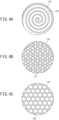
- Examples of the arrangement manner of the grooves 131 include grooves 131 in a lattice pattern as in FIG. 3B , grooves 132 in a spiral pattern as in FIG. 4A , grooves 133 in a pattern in which lines surrounding a plurality of triangular projections are connected as in FIG. 4B , and grooves 134 in a pattern in which lines surrounding a plurality of hexagonal projections are connected as in FIG. 4C .
- the grooves 131 may be arranged in any pattern as long as the condition a and the conditions 1 to 5 are satisfied. As long as the condition a and the conditions 1 to 5 are satisfied, the depth of the groove 131 may be smaller than the thickness of the hard layer 140.
- the soft layer 150 is not exposed to the polishing face 130.
- grooves 131 satisfy the condition a and the conditions 1 to 5 and polishing is performed with a commonly used polishing robot, the displacement of the hard layer 140 can be ensured when the polishing face 130 is pressed against a curved face of a resin coated face, and the polishing face 130 can be easily bent while a reduction of the contact area between the polishing face 130 and a resin coated face due to the formation of grooves 131 is suppressed. Hence, the polishing efficiency can be maintained, and the grooves 131 can be prevented from clogging.
- a chamfer may be formed in order to suppress scratches when especially a concave curved face of an object to be polished is polished.
- the chamfer may have any shape.
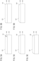
- a beveled chamfer 141 as in FIG. 5A a curved chamfer 142 as in FIG. 5B , a multi beveled chamfer 143 as in FIG. 5C , or chamfers 144, 145 having a combination of a beveled shape and a curved shape as in FIGS. 5D and 5E may be formed.
- the chamfer may have any angle.
- the angle ⁇ between the chamfer 141 and the polishing face 130 is preferably not less than 125° and less than 180° and more preferably 140° or more and 165° or less. Within the range, scratches are more unlikely to be formed when a concave face is polished.
- the polishing composition preferably includes an emulsion containing abrasives and at least one additive selected from an oleum, an emulsion stabilizer, and a thickener.
- an emulsion containing abrasives and at least one additive selected from an oleum, an emulsion stabilizer, and a thickener.
- a highly viscous polishing composition is easily prepared.
- the highly viscous polishing composition is unlikely to drip when applied to a surface to be polished that is perpendicular or inclined to the ground and is advantageous for polishing a three-dimensional object to be polished.
- the highly viscous polishing composition may be any polishing composition having such a viscosity as to prevent the dripping, and, for example, the viscosity is preferably 1 mPa ⁇ s or more, more preferably 2,000 mPa ⁇ s or more, even more preferably 4,000 mPa ⁇ s or more, and further preferably 5,000 mPa ⁇ s or more.
- the viscosity is preferably 40,000 mPa ⁇ s or less, more preferably 30,000 mPa ⁇ s or less, even more preferably 13,000 mPa ⁇ s or less, and further preferably 10,000 mPa ⁇ s or less.
- a polishing composition having such properties may not contain the above additives.
- polishing composition will next be described in detail.
- the polishing composition is not specifically limited.
- a slurry containing abrasives selected from particles of a carbide of silicon such as silicon carbide, particles of an oxide of silicon or a metal element, such as silicon dioxide or silica, aluminum oxide or alumina, ceria, titania, zirconia, iron oxide, and manganese oxide, a silicate compound such as zircon, organic particles of a thermoplastic resin, and organic-inorganic composite particles can be used.
- a slurry containing abrasives including at least one of aluminum oxide, cerium oxide, and zirconium oxide can be used.
- an alumina slurry which enables a high polishing removal rate and is easily available, is more preferably used.
- the alumina for example, includes aluminas different in crystal morphology, such as ⁇ -alumina, ⁇ -alumina, ⁇ -alumina, and ⁇ -alumina, and also includes an aluminum compound called hydrated alumina. From the viewpoint of the polishing removal rate, abrasives mainly including ⁇ -alumina are preferably used as the abrasives.
- a mixture of alumina and zircon can also be preferably used as the abrasives, for example.
- the ⁇ -fraction is not specifically limited but is preferably 30% or more, more preferably 50% or more, and even more preferably 70% or more. Within the range, a high polishing removal rate can be achieved while a good surface shape is maintained.
- the ⁇ -fraction can be determined from the integrated intensity ratio of the (113) plane diffraction line in an X-ray diffraction analysis.
- the abrasives may have any average secondary particle diameter, but the average secondary particle diameter is preferably 15.0 ⁇ m or less and more preferably 5.0 ⁇ m or less.
- a polishing composition containing abrasives having a smaller average secondary particle diameter has a higher dispersion stability and is less likely to scratch the surface to be polished of an object to be polished.
- the average secondary particle diameter of abrasives can be determined by using a pore electrical resistance method (measurement apparatus: MultiSizer III manufactured by Beckman Coulter, Inc.).
- the content of the abrasives in the polishing composition is not specifically limited but is preferably 0.1% by mass or more, more preferably 5% by mass or more, and even more preferably 10% by mass or more. As the content of the abrasives increases, the polishing removal rate is likely to increase. When the content of the abrasives is within the above range, the polishing removal rate is easily increased to a particularly suitable level in practice.
- the content of the abrasives is not specifically limited but is preferably 50% by mass or less, more preferably 35% by mass or less, and even more preferably 30% by mass or less.
- the content of the abrasives is within the range, the cost of the polishing composition can be suppressed.
- surface defects can be further suppressed on the surface of an object to be polished after polishing with the polishing composition.
- the object to be polished may include at least one selected from the group consisting of a resin material, an alloy material, a metal, a metalloid, a metal oxide material, a carbide material, a nitride material, a metalloid oxide material, and a glass material.
- the polishing composition pertaining to the present embodiment contains an additive.
- the additive include an oleum, an emulsion stabilizer, and a thickener.
- the additives may be used singly or as a mixture of two or more of them. Adding the additive is likely to improve the emulsion stability.
- a surface modifier, an alkali, or the like described later may be used as the additive.
- oleum examples include synthetic oils such as liquid paraffin, polybutene, an ⁇ -olefin oligomer, an alkylbenzene, a polyol ester, a phosphate ester, and silicone oil, mineral oils such as spindle oil, neutral oil, and bright stock, vegetable oils and fats such as castor oil, soybean oil, coconut oil, linseed oil, cottonseed oil, rapeseed oil, tung oil, and olive oil, and animal oils and fats such as beef tallow, squalane, and lanolin.
- synthetic oils such as liquid paraffin, polybutene, an ⁇ -olefin oligomer, an alkylbenzene, a polyol ester, a phosphate ester, and silicone oil
- mineral oils such as spindle oil, neutral oil, and bright stock
- vegetable oils and fats such as castor oil, soybean oil, coconut oil, linseed oil, cottonseed oil, rapeseed oil,
- emulsion stabilizer examples include polyhydric alcohols such as glycerol, ethylene glycol, and propylene glycol and aliphatic alcohols such as cetyl alcohol and stearyl alcohol.
- the thickener examples include synthetic thickeners such as polyacrylic acid, a sodium polyacrylate (such as a completely neutralized polyacrylic acid, a partially neutralized polyacrylic acid, and an associative alkali-soluble polyacrylic acid (acrylic polymer)), cellulose thickeners such as carboxymethyl cellulose and carboxyethyl cellulose (hemi-synthetic thickeners), and natural thickeners such as agar, carrageenan, a layered silicate compound, xanthan gum, and gum arabic.
- synthetic thickeners such as polyacrylic acid, a sodium polyacrylate (such as a completely neutralized polyacrylic acid, a partially neutralized polyacrylic acid, and an associative alkali-soluble polyacrylic acid (acrylic polymer)
- cellulose thickeners such as carboxymethyl cellulose and carboxyethyl cellulose (hemi-synthetic thickeners)
- natural thickeners such as agar, carrageenan, a layered si
- alkali examples include inorganic alkalis such as sodium hydroxide, potassium hydroxide, and ammonia and organic alkalis such as triethanolamine. Adding an alkali allows polyacrylic acid to exert thickening effect.
- the thickener may be a Newtonian fluid or a non-Newtonian fluid.
- the polishing composition may appropriately contain, in addition to the above components, additional components such as a lubricant, an organic solvent, and a surfactant, as needed.
- the lubricant may be, for example, a synthetic oil, a mineral oil, a vegetable oil and fat, or a combination of them.
- the organic solvent may be, for example, a hydrocarbon solvent as well as an alcohol, an ether, a glycol, or glycerol.
- the surfactant may be, for example, what is called an anionic surfactant, a cationic surfactant, a nonionic surfactant, or an amphoteric surfactant.
- the polishing pad pertaining to the present invention has a shape selected so as to decrease the reduction rate of the polishing efficiency due to clogging or the like even when used continuously without brushing. In other words, a polishing pad having a smaller reduction rate of the polishing efficiency can be achieved.
- polishing pad pertaining to the present invention for polishing can suppress the reduction in the polishing efficiency with polishing time.
- the frequency of brushing which is performed while polishing operation is suspended to clear clogging or the like that decreases the polishing efficiency, can be reduced.
- the groove 131 partially reaches the outer edge of the polishing face 130 and is open, and this facilitates discharge of a polishing composition through the grooves 131 outside the polishing face 130 and also facilitates discharge of unnecessary polishing waste. This is also advantageous to suppress clogging.
- the highly viscous polishing composition as an emulsion has a lower flowability than a polishing composition having a low viscosity.
- the polishing composition and/or polishing waste adhering to a polishing pad is difficult to discharge outside the polishing pad. Solids such as abrasives and polishing waste that are not discharged outside the polishing pad but stay on the polishing pad can cause clogging.
- a highly viscous polishing composition may contain oil or have a small water content.
- a highly viscous polishing composition is supplied in a smaller amount onto a polishing face during polishing than a polishing composition having a low viscosity.
- the polishing interface is likely to be in a dry condition, and the polishing heat increases greatly as compared with a polishing composition having a low viscosity.
- a surface to be polished is larger than the polishing face of the polishing pad, and accordingly the whole region of the polishing face is in contact with the surface to be polished for a long time during polishing. It is thus likely to be difficult to discharge heat from the polishing face. Consequently, liquid components in a polishing composition are likely to evaporate, and this makes it more difficult to discharge solids such as abrasives in a polishing composition and polishing waste. On a polishing face at a high temperature, polishing waste including a resin may be fixed to the polishing pad. These conditions are more likely to cause clogging.
- polishing pad in the embodiment allows residual solids to move into grooves.
- the space in grooves contributes to suppressing the increase of polishing heat.
- the polishing pad in the embodiment exerts excellent clogging suppressive effect when applied to polishing with a highly viscous polishing composition.
- the polishing pad in the embodiment can also be suitably used even with a polishing composition that contains a highly volatile dispersion medium and is likely to cause a dry condition or with a polishing composition that has a high abrasive concentration and is likely to generate residual solids.
- polishing with a polishing robot has been described, but the polishing pad pertaining to the present embodiment can be applied even to manual polishing with a manual polisher 50 illustrated in FIG. 6 without a robot.
- signs 70 and 80 are hand parts of the manual polisher 50
- sign 40 is a polishing pad attachment part
- sign 110 is a polishing pad.
- a polishing pad 1A in a third embodiment includes a disk-shaped polishing layer 2 having a polishing face 21 and a truncated cone-shaped support layer 3.
- the polishing face 21 is the face to be pressed against a surface to be polished of a polishing target when the polishing target is polished.
- a bottom face having a larger diameter of the two bottom faces of the truncated cone that forms the support layer 3 is a face 31 on the polishing layer 2, and a bottom face having a smaller diameter is a support face 32 of the support layer 3.
- the support face is a face that applies a pressing force to the polishing pad.
- the support layer 3 is fixed to a face 22 opposite to the polishing face 21 of the polishing layer 2 through an adhesive or a double-sided adhesive tape while the center of the circular bottom face of the support layer 3 is aligned with the center of the disk face of the polishing layer 2.
- the whole face 31 of the support layer 3 on the polishing layer 2 is the joint face to the polishing layer 2.
- the ratio ( ⁇ r/h) of the difference ⁇ r between the radius r31 of the face 31 of the support layer 3 on the polishing layer 2 and the radius r32 of the support face 32 to the height h of the support layer 3 is preferably larger and is, for example, more than 0.60.
- ⁇ r/h 0.63
- ⁇ r/h 0.83
- ⁇ r/h 1.17
- ⁇ r/h 1.50.
- the materials of the polishing layer 2 and the support layer 3 are the same as those for the polishing pad 1 in the first embodiment.
- grooves may be formed on the polishing face as with the polishing pad 110 in the second embodiment.
- the support layer 3 has a truncated cone shape, and thus the edge portion of the support layer 3 is bent more easily than the center portion. This can reduce the pressure on the edge portion of the polishing face. Accordingly, a coating can be less scratched as compared with a cylindrical polishing pad in which a support layer 3 has the same diameter as a polishing layer 2.
- the pressure applied to the edge portion of the polishing layer 2 is smaller than the pressure applied to the center portion as compared with a cylindrical polishing pad in which a support layer 3 has the same diameter as a polishing layer 2. This can suppress scratches when a concave face is polished.
- a polishing pad 1B in a fourth embodiment includes a disk-shaped polishing layer 2 having a polishing face 21 and a cylindrical support layer 3.
- the diameter a2 of the polishing layer 2 is larger than the diameter a3 of the support layer 3.
- the polishing face 21 is the face to be pressed against a surface to be polished of a polishing target when the polishing target is polished.
- the support layer 3 is fixed to a face 22 opposite to the polishing face 21 of the polishing layer 2 through an adhesive or a double-sided adhesive tape while the circular center of the support layer 3 is aligned with the circular center of the polishing layer 2.
- the face 31 of the support layer 3 on the polishing layer 2 except the edge portion is the joint face to the polishing layer 2.
- the face 31 of the support layer 3 on the polishing layer 2 and the support face 32 have the same diameter.
- the materials of the polishing layer 2 and the support layer 3 are the same as those for the polishing pad 1 in the first embodiment.
- the face 31 of the support layer 3 on the polishing layer 2 has an area (edge area) to which no polishing layer 2 is fixed, and when a coating face including a concave curved face is polished, the edge portion of the soft support layer 3 comes into contact with the coating face. Accordingly, scratches on a coating can be suppressed.
- Polishing pads of samples No. 1-1 to No. 1-7 shown below were prepared.
- the polishing pads of samples No. 1-1 to No. 1-7 are each a polishing pad 1 having the structure illustrated in FIGS. 1A and 1B , and the polishing layer 2 has a disk shape having a diameter of 150 mm and a thickness of 1.3 mm, is a suede type, and has a C hardness of 50.
- the polishing face 21 of the polishing layer 2 has a diameter of 150 mm.
- the support layer 3 is a disk having a diameter of 150 mm and a thickness of 20 mm.
- the support layers 3 are different in hardness and density.
- the support layer 3 is made from a urethane foam.
- the F hardnesses of the support layers 3 were 87 in No. 1-1, 89 in No. 1-2, 63 in No. 1-3, 51 in No. 1-4, 42 in No. 1-5, 42 in No. 1-6, and 36 in No. 1-7.
- the densities of the support layers 3 were 50 kg/m 3 in No. 1-1, 65 kg/m 3 in No. 1-2, 26 kg/m 3 in No. 1-3, 55 kg/m 3 in No. 1-4, 40 kg/m 3 in No. 1-5, 35 kg/m 3 in No. 1-6, and 28 kg/m 3 in No. 1-7.
- the elongations of the support layers 3 were 70% or more in No. 1-1, more than 100% in No. 1-2, more than 250% in No. 1-3, more than 80% in No. 1-4, more than 100% in No. 1-5, and more than 200% in No. 1-6 and No. 1-7.
- the F hardness of the support layer 3 was determined as follows: an "ASKER Durometer Type F" manufactured by KOBUNSHI KEIKI CO.,LTD. was used; a disk-shaped pressure foot was gently placed on a polishing pad 1 with a support layer 3 facing up; and the self-weight of the durometer was read as the measurement pressure.
- the elongation of the support layer 3 was determined by a method in accordance with JIS K6400-5.
- a semicylinder including a concave curved face or a convex curved face having a curvature radius of 250 mm was prepared, and the contact area ratio of the polishing pad of each of the samples No. 1-1 to No. 1-7 with the concave curved face or the convex curved face was determined.
- a surface pressure distribution measurement system with a pressure-sensitive sensor sheet was used to determine a contact area in a condition of a load of 40 N or a load of 80 N, and the contact area ratio was calculated.
- the pressure distribution and the cumulative pressure distribution were also determined.
- a load of 40 N corresponds to the load on a polishing pad during common hand polishing
- a load of 80 N corresponds to the load on a polishing pad during polishing a portion difficult to polish, such as a corner.
- the used surface pressure distribution measurement system was a surface pressure distribution measurement system for wafers manufactured by Suzuki Scientific Instruments,Inc., and the details are as described below.
- Type C-SCAN 12S, sensor thickness: 0.1 mm, spatial resolution: row d: 4.1, line d: 4.1, the number of sensors: 7,744, pressure-sensitive portion size: 361 ⁇ 361 mm, maximum measurement pressure: 50 kPa
- the semicylinder was placed with the opening facing up; a polishing pad was placed so as to be located at the lowest position in the opening; and a load was applied in a direction along the central axis of the disk included in a polishing pad.
- the semicylinder was placed with the opening facing down; a polishing pad was placed on the top; and a load was applied in a direction along the central axis of the disk included in the polishing pad.
- Table 1 shows the results of contact area ratio together with the structures of the support layers.
- Table 2 shows the pressure distributions at a load of 80 N, and Table 3 shows the cumulative pressure distributions at a load of 80 N. The pressure distribution indicates the ratio of a portion under a predetermined pressure range to a contact area. [Table 1] No.
- Support layer Contact area ratio [%]: a curvature radius of 250 mm F hardness Density [kg/m 3 ] Yield elongation [%] Concave curved face Convex curved face 40 N 80 N 40 N 80 N 1-1 87 50 70 or more 21 49 27 38 1-2 89 65 more than 100 32 61 32 42 1-3 63 26 more than 250 100 95 66 89 1-4 51 55 more than 80 91 98 72 85 1-5 42 40 more than 100 100 95 86 84 1-6 42 35 more than 200 91 94 82 85 1-7 36 28 more than 200 100 94 94 92 [Table 2] No.
- the polishing pads of No. 1-3 to No. 1-7 corresponding to the examples of the present invention had a contact area ratio of 90% or more to the concave curved face having a curvature radius of 250 mm, whereas the polishing pads of No. 1-1 and No. 1-2 corresponding to the comparative examples had a contact area ratio of 61% or less.
- the polishing pads of No. 1-3 to No. 1-7 corresponding to the examples of the present invention had a contact area ratio of 66% or more and 94% or less to the convex curved face having a curvature radius of 250 mm, whereas the polishing pads of No. 1-1 and No. 1-2 corresponding to the comparative examples had a contact area ratio of 27% or more and 42% or less.
- the results reveal that the polishing pads of No. 1-3 to No. 1-7 corresponding to the examples of the present invention have a higher following performance to a concave curved face and a convex curved face than the polishing pads of No. 1-1 and No. 1-2 corresponding to the comparative examples.
- the portion under a pressure range of 14.6 kPa or less was 96.6% or more and 99.9% or less, whereas in the polishing pads of No. 1-1 and No. 1-2 corresponding to the comparative examples, the portion was 83.4% or more and 95.8% or less.
- the polishing pads of No. 1-3 to No. 1-7 corresponding to the examples of the present invention are unlikely to generate locally high pressure when pressed against a concave curved face or a convex curved face as compared with the polishing pads of No. 1-1 and No. 1-2 corresponding to the comparative examples.
- the portion under a pressure range of 14.6 kPa or less was 98.9% or more and 99.9% or less in the contact area and exhibited a higher ratio than the polishing pads of No. 1-3 and No. 1-7.
- the polishing pads of No. 1-4 and No. 1-5 had a particularly high effect of suppressing locally high pressure.
- An object to be polished was a 300 ⁇ 600 mm metal plate coated with a synthetic resin paint and had a corrugated plate shape including a concave curved face having a curvature radius of 250 mm.
- the outermost coating had a thickness of 20 ⁇ m.
- the surface to be polished was a coating face of a synthetic resin, and the surface to be polished was larger than the polishing face.
- the used polishing apparatus was an electric single polisher. While the polishing pad of each sample was pressed against the surface to be polished, a polishing composition containing abrasives having an average particle diameter of 0.4 ⁇ m was supplied onto the surface to be polished and was spread with the polishing pad, and then the polisher was rotated to perform polishing.
- the polishing conditions were the same in all the samples.
- the polishing pads of No. 1-3 to No. 1-7 corresponding to the examples of the present invention were excellent in in-plane uniformity of the polished state as compared with the polishing pads of No. 1-1 and No. 1-2 corresponding to the comparative examples.
- polishing pads of No. 1-8 to No. 1-10 polishing pads having polishing face diameters of 35 mm (No. 1-8), 50 mm (No. 1-9), and 75 mm (No. 1-10) were prepared.
- the diameter of the support layer of each polishing pad was the same as the diameter of the polishing layer.
- the thickness and the shape of the polishing layer, the thickness and the shape of the support layer, the density of the support layer, the F hardness of the support layer, and the elongation were the same as those of the above polishing pad of No. 1-4.
- Semicylinders including concave curved faces having curvature radii of 47 mm, 100 mm, and 250 mm were prepared, and a test of determining the contact area ratios of the above polishing pad of No. 1-4 and the polishing pads of No. 1-8 to No. 1-10 with the respective concave curved faces was performed.
- the test method was the same as the method using the above surface pressure distribution measurement system and was performed at a load of 40 N.
- Table 4 shows the results. Table 4 also shows the ratios of the diameter of the polishing face to the curvature radius of the concave curved face.
- Table 4 No. Polishing layer Polishing face diameter/curvature radius Contact area ratio at 40 N [%] Polishing face diameter [mm] Curvature radius of concave curved face [mm] Curvature radius of concave curved face [mm] 47 100 250 47 100 250 1-8 35 0.74 0.35 0.14 100 100 100 1-9 50 1.06 0.50 0.20 95 100 100 1-10 75 1.60 0.75 0.30 74 100 100 1-4 150 3.19 1.50 0.60 0 34 91
- the polishing face As shown in Table 4, as a concave curved face as the surface to be polished has a larger curvature radius, the polishing face is likely to have a larger contact area ratio. As the ratio of the diameter of a polishing face to the curvature radius of a concave curved face, or "the diameter of a polishing face/the curvature radius of a concave curved face" is smaller, the contact area ratio is likely to be larger. In other words, it is revealed that as "the diameter of a polishing face/the curvature radius of a curved face" is smaller, a higher following performance to a concave curved face is achieved.
- Polishing pads of No. 2-1 to No. 2-17 having the following structures were prepared.
- the polishing pads of No. 2-1 to No. 2-17 each included a hard layer (polishing layer) including a disk-shaped nonwoven fabric having a diameter of 15 cm and a thickness of 3 mm and a soft layer (support layer) including a disk-shaped polyurethane foam having a diameter of 15 cm and a thickness of 20 mm.
- a hard layer including a disk-shaped nonwoven fabric having a diameter of 15 cm and a thickness of 3 mm
- a soft layer support layer
- the hard layer has a sparse portion area ratio of 95%.
- the hard layer has an A hardness of 70, and the soft layer has an F hardness of 90.
- the A hardness of the hard layer was determined by a method in accordance with JIS K 6253 and was the minimum value of values measured at five points at intervals of 3 mm.
- the ratio of the diameter of the layer having the polishing face to the diameter of the polishing pad attachment part is 1:1.2.
- the polishing pad of No. 2-1 is a polishing pad without grooves, and the polishing layer has a thickness of 1.3 mm.
- the polishing pads of No. 2-2 to No. 2-17 have grooves in a lattice pattern illustrated in FIG. 3B .
- the groove width, the pitch, the groove depth, the thickness of the polishing layer, the ratio S m /S k (groove area ratio), and the ratio V m/ S k (groove volume cm 3 /polishing face area cm 2 ) of each polishing pad are as shown in Table 5.
- the pitch is the distance between grooves and is, for example, the distance of the left edges of grooves.
- the groove area ratio is the area proportion of grooves to a whole polishing face and is calculated by "groove area/polishing face area”.
- the groove area is calculated by "polishing face area - projection area”.
- the "groove volume cm 3 " in “groove volume cm 3 /polishing face area cm 2” is "polishing face area cm 2 ⁇ groove area ratio % ⁇ groove depth cm".
- the object to be polished is an 800 mm ⁇ 600 mm flat metal plate coated with a synthetic resin paint and has a clear coating layer having a thickness of 30 ⁇ m.
- the surface to be polished is a coated face of a synthetic resin.
- the used polishing composition was prepared as follows: 12% by mass of alumina as abrasives, 16% by mass of isoparaffin hydrocarbon, 2% by mass of polyoxyalkylene alkyl ether, and 1% by mass of polyacrylic acid polymer were added to water; the whole was stirred at room temperature (25°C) to give a dispersion liquid (O/W emulsion); and sodium hydroxide was added to give a composition having a viscosity of 8,000 mPa ⁇ s.
- the alumina had an average secondary particle diameter of 1.3 ⁇ m and an ⁇ -fraction of about 95%.
- the average secondary particle diameter was the D 50 value determined by pore electrical resistance method by using a precision particle diameter distribution analyzer (MultiSizer III manufactured by Beckman Coulter, Inc.).
- the ⁇ -fraction was calculated from the integrated intensity ratio of the (113) plane diffraction line in an X-ray diffraction analysis by using an X-ray analyzer (Ultima-IV manufactured by Rigaku Corporation).
- an X-ray analyzer Ultima-IV manufactured by Rigaku Corporation
- MIRAFLEX S500 a polishing composition produced by the present applicant and having a viscosity of 8,000 mPa ⁇ s was used.
- the polishing pads of No. 2-1 to No. 2-17 were used to perform polishing test in the following conditions.
- a polishing robot (“Robot polishing system” manufactured by TRI ENGINEERING Co.,Ltd.) in which a constant pressure mechanism and a polisher (“PE-201” manufactured by RYOBI LIMITED) were attached to the tip of an arm of an industrial robot (“MOTOMAN-GP25” manufactured by YASKAWA Electric Corporation) was used to perform polishing (rough polishing) while the polishing pressure was controlled at a constant value.
- the pressure is controlled by a control command in terms of force value.
- the operation was performed in the following order: the pad was allowed to approach the object to be polished; then pressure application was started; and the polisher rotation was started.
- Approaching a polishing start point is an operation of transferring a polishing pad to a position above the polishing start point in a pressurization axis where the "pressurization axis" is the axis extending along the pressure application direction. After the approaching, the polishing pad may be in contact with the object to be polished or may not be in contact. When the polishing pad is not in contact, the operation of pressure application start allows the polishing pad to come into contact with the object to be polished.
- the polisher was transferred to an avoidance position where the polishing pad was not in contact with the polished object, before releasing the pressure application and stopping the polisher rotation. Then, the pressure application was released, and the polisher rotation was stopped.
- the object to be polished was polished with the polishing pad attached to the polisher, at an angle of 1° between the polishing traveling direction and the direction away from the object to be polished.
- polishing pads of No. 2-1 to No. 2-17 and the polished object after the above polishing test were subjected to the test and evaluation of polishing performance by the following procedure.
- the removal amount of a surface to be polished was determined as follows: the coating thicknesses before and after polishing were determined with an electromagnetic induction film thickness meter; and the difference between them was calculated as the removal amount. The removal amount was divided by the polishing time to determine the polishing removal rate. The polishing removal rates were determined at nine positions on a polished surface. The test was repeated five times, and the average polishing removal rate was calculated from 45 polishing removal rates (9 positions ⁇ 5 times). The nine positions were located at least 150 mm inside the peripheral part of a 600 mm ⁇ 800 mm portion as a part of a polished surface. The calculated average polishing removal rate was regarded as the polishing efficiency.
- a sample having a polishing efficiency of 0.20 ⁇ m/min or more was graded as A; a sample having a polishing efficiency of not less than 0.15 ⁇ m/min and less than 0.20 ⁇ m/min was graded as B; a sample having a polishing efficiency of not less than 0.10 ⁇ m/min and less than 0.15 ⁇ m/min was graded as C; and a sample having a polishing efficiency of less than 0.10 ⁇ m/min was graded as D.
- a Wave-Scan Dual (coating surface texture measurement apparatus) (manufactured by BYK Gardner) was used to determine wavinesses Wd and We on a polished surface.
- Wd represents the magnitude of waviness of components having a wavelength of 3 to 10 mm
- We represents the magnitude of waviness of components having a wavelength of 10 to 20 mm.
- the measurement was performed at five points near the center of a coating as a polished surface, and the averages of Wd and We at the five points were calculated as Wd and We, respectively, after polishing.
- a sample having a Wd of 2.5 or less was graded as A; a sample having a Wd of more than 2.5 and not more than 3.5 was graded as B; a sample having a Wd of more than 3.5 and not more than 4.5 was graded as C; and a sample having a Wd of more than 4.5 was graded as D.
- a sample having a We of 3 or less was graded as A; a sample having a We of more than 3 and not more than 4 or less was graded as B; a sample having a We of more than 4 and not more than 5 was graded as C; and a sample having a We of more than 5 was graded as D.
- Polishing was performed without brushing, and the polishing efficiency from 0 to 5 minutes after the polishing start and the polishing efficiency from 15 to 20 minutes after the polishing start were determined. Then, [(1 - (the polishing efficiency from 15 to 20 minutes after the polishing start)/(the polishing efficiency from 0 to 5 minutes after the polishing start)] ⁇ 100 [%] was calculated as the polishing efficiency reduction rate.
- a sample having a polishing efficiency reduction rate of 30% or less was graded as A; a sample having a polishing efficiency reduction rate of more than 30% and not more than 50% was graded as B; a sample having a polishing efficiency reduction rate of more than 50% and not more than 70% was graded as C; and a sample having a polishing efficiency reduction rate of more than 70% was graded as D.
- a one-shot 3D-profilometer VR-3200 manufactured by Keyence Corporation was used, and line roughnesses were measured at three points (12 points in total) 40 mm apart from the origin that was the center of the polishing face of a polishing pad, in each of the four (0°, 90°, 180°, and 270°) directions at a measurement magnification of 12-fold in a measurement range of 24 mm ⁇ 18 mm, and the average was calculated.
- space between grooves were analyzed in terms of multiple line roughness, and the average Ra was calculated as "pad Ra after polishing" representing the clogging of a polishing pad.
- a sample having a pad Ra after polishing of 300 ⁇ m or more was graded as A; a sample having a pad Ra after polishing of not less than 200 ⁇ m and less than 300 ⁇ m was graded as B; a sample having a pad Ra after polishing of not less than 100 ⁇ m and less than 200 ⁇ m was graded as C; and a sample having a pad Ra after polishing of less than 100 ⁇ m was graded as D.
- the temperature on the polishing face of a polishing pad (polishing face temperature after polishing) and the temperature on a polished surface were determined.
- the temperature may be determined by any method, and, for example, an infrared thermometer was used to determine the temperatures on the polishing face of a polishing pad and a polishing face.
- the evaluation criteria of each of the polishing face temperature after polishing and the polished surface temperature were as follows: a sample having a temperature of 28°C or less was graded as A; a sample having a temperature of more than 28°C and not more than 32°C was graded as B; a sample having a temperature of more than 32°C and less than 40°C was graded as C; and a sample having a temperature of more than 40°C was graded as D.
- a semicylinder including a concave curved face or a convex curved face having a curvature radius of 250 mm was prepared, and the contact area ratio of the polishing pad of each sample (except No. 2-4) with the concave curved face or the convex curved face was determined.
- a surface pressure distribution measurement system with a pressure-sensitive sensor sheet was used to determine the contact area in a condition of a load of 39.2 N (9.8 ⁇ 4 kgf), and the contact area ratio was calculated.
- the used surface pressure distribution measurement system was a surface pressure distribution measurement system for wafers manufactured by Nitta Corporation, and the details are as described below.
- Type C-SCAN 12S, sensor thickness: 0.1 mm, spatial resolution: row d: 4.1, line d: 4.1, the number of sensors: 7,744, pressure-sensitive portion size: 361 ⁇ 361 mm, maximum measurement pressure: 50 kPa
- the semicylinder was placed with the opening facing up; a polishing pad was placed so as to be located at the lowest position in the opening; and a load was applied in a direction along the central axis of the disk included in a polishing pad.
- the semicylinder was placed with the opening facing down; a polishing pad was placed on the top; and a load was applied in a direction along the central axis of the disk included in the polishing pad.
- a sample having a contact area ratio of 85% or more was graded as A; a sample having a contact area ratio of not less than 75 and less than 85% was graded as B; a sample having a contact area ratio of not less than 65 and less than 75% was graded as C; and a sample having a contact area ratio of less than 75% was graded as D.
- a sample having a contact area ratio of 80% or more was graded as A; a sample having a contact area ratio of not less than 70 and less than 80% was graded as B; a sample having a contact area ratio of not less than 60 and less than 70% was graded as C; and a sample having a contact area ratio of less than 70% was graded as D.
- a sample having nine A grades or having eight A grades and one B grade was evaluated as A; a sample having only A and B grades with two or more B grades was evaluated as B; a sample having at least one C grade was evaluated as C; and a sample having at least one D grade was evaluated as D.
- Wd We 2-1 0.18 B 2.4 A 4.8 C - D - D - - - - 89 A 76 B D 2-2 0.23 A 2.7 B 2.7 A 57% C 32 C 27.0 A 28.5 B 83 B 70 B C 2-3 0.21 A 0.6 A 0.9 A 26% A 141 C 31.9 B 33.4 C 79 B 65 C C 2-4 0.27 A 2.4 A
- Table 5 and Table 6 reveal that, by using, of the polishing pads satisfying the condition a (a polishing face has a diameter of 10 mm or more and 200 mm or less), the polishing pad having grooves satisfying the conditions 3 and 4 (groove area ratio and groove volume/polishing face area), clogging can be suppressed, and the reduction rate of the polishing efficiency can be decreased. As a result, the frequency of brushing for pad cleaning can be reduced.
- the holding power of a polishing composition can be increased.
- the holding power can be increased, and the polishing pad can be less clogged. It was, however, ascertained that when the ratio of the groove volume to the polishing face area exceeded an appropriate value, the polishing face had defects, clogging was caused, or the orange peel removal efficiency deteriorated.
Landscapes
- Engineering & Computer Science (AREA)
- Mechanical Engineering (AREA)
- Finish Polishing, Edge Sharpening, And Grinding By Specific Grinding Devices (AREA)
Abstract
Description
- The present invention relates to a polishing pad and a polishing method using the polishing pad.
- Buffing has been known as a processing method to smooth a surface to be polished, such as a coated body face of automobiles (for example, PTL 1). Such a surface to be polished includes a curved face. The buffing is a polishing method by rotating a buffing wheel (buff) that is made from a fabric or a similar material and has a periphery (surface) with various abrasives or the like.
- The buffing, however, can fail to remove waviness on a surface to be polished and is difficult to achieve a beautiful surface finish.
- To solve the problem, the present inventors have proposed a polishing method capable of reducing waviness on a surface to be polished including a curved face.
PTL 2 discloses a polishing pad having a structure allowing a polishing face that is to come into contact with a surface to be polished at the time of polishing to follow a curved face portion of the surface to be polished. The polishing pad has a two-layer structure including a hard resin layer having a polishing face and a soft resin layer supporting the hard resin layer. The soft resin layer is disclosed to have a hardness of 30 degrees or less in terms of E hardness in accordance with JIS K 6253. -
PTL 3 discloses a polishing pad with a support layer. The polishing pad includes a polishing layer having a polishing face and a support layer fixed to a face opposite to the polishing face of the polishing layer. The support layer is softer than the polishing layer. The support layer is disclosed to have a hardness of 30 or more and 90 or less in terms of F hardness (determined with an "ASKER Durometer Type F" manufactured by KOBUNSHI KEIKI CO.,LTD.). - PTL 4 discloses a polishing pad for polishing a surface to be polished by using a polishing slurry containing abrasives in order to achieve a better surface finish, and grooves are formed on a polishing face. The polishing face is formed from a polyurethane foam or a nonwoven fabric. By forming the grooves, the polishing face easily follows a curved face of a polishing target, and the polishing efficiency is improved.
-
- PTL 1:
JP 2012-251099 A - PTL 2:
JP 2016-47566 A - PTL 3:
JP 2017-148919 A - PTL 4:
JP 2016-047566 A - The polishing pads disclosed in
PTLs - The present invention is intended to provide a polishing pad capable of improving the performance of following a curved face portion of a surface to be polished.
- To solve the problem, an aspect of a polishing pad of the present invention includes a polishing layer having a polishing face and a support layer that is softer than the polishing layer and is fixed to a face opposite to the polishing face of the polishing layer, and the support layer has a hardness of not less than 30 and less than 70 in terms of F hardness.
- According to a polishing pad in an aspect of the present invention, the performance of following a curved face portion of a surface to be polished should be improved.
-
-
FIGS. 1A and 1B are views illustrating a polishing pad in a first embodiment;FIG. 1A is a perspective view illustrating the polishing face side; andFIG. 1B is a sectional view taken along line A-A; -
FIG. 2 is a schematic configuration view illustrating an example of a polishing robot to which the present invention is applied; -
FIGS. 3A to 3C are views illustrating a polishing pad in a second embodiment;FIG. 3A is a perspective view illustrating the polishing face side;FIG. 3B is a plan view of the polishing face;FIG. 3C is a sectional view taken along line A-A inFIG. 3A and FIG. 3B ; and inFIG. 3A , the grooves inFIG. 3B are not illustrated; -
FIGS. 4A to 4C are plan views of groove arrangement examples of the polishing pad in the second embodiment other than the arrangement inFIG. 3B ; -
FIGS. 5A to 5E are side views illustrating chamfer shapes on polishing faces; -
FIG. 6 is a perspective view of a manual polisher; -
FIG. 7 is a view illustrating a polishing pad in a third embodiment; and -
FIG. 8 is a view illustrating a polishing pad in a fourth embodiment. - Embodiments of the present invention will now be described, but the present invention is not limited to the embodiments described below. The embodiments described below include technologically preferred limitations for carrying out the present invention, but the limitations are not essential requirements of the invention.
- As illustrated in
FIGS. 1A and 1B , apolishing pad 1 in the embodiment includes a disk-shaped polishing layer 2 having a polishingface 21 and acylindrical support layer 3. The polishingface 21 is the face to be pressed against a surface to be polished of a polishing target when the polishing target is polished. Thesupport layer 3 is fixed to aface 22 opposite to the polishingface 21 of thepolishing layer 2 with an adhesive or a double-sided adhesive tape. - The polishing
layer 2 is a suede or a nonwoven fabric and has a thickness of 0.5 mm or more and 5.0 mm or less. Thepolishing layer 2 has a hardness of 40 or more and 90 or less in terms of hardness (C hardness) determined immediately after close contact with a pressure foot in the test method defined by "Spring hardness test, type C test method" inappendix 2 in JIS K7312: 1996. - In the
polishing layer 2, theedge 211 on the polishingface 21 is chamfered by cutting. Thepolishing layer 2 may not be chamfered. - The
support layer 3 is made from a polyurethane foam. Thesupport layer 3 has a hardness of not less than 30 and less than 70 in terms of F hardness (determined with an "ASKER Durometer Type F" manufactured by KOBUNSHI KEIKI CO.,LTD. and specifically determinable by, for example, a method in examples). Thesupport layer 3 has a density of 20 kg/m3 or more and 60 kg/m3 or less. Thesupport layer 3 has a thickness of 2.0 mm or more and 50 mm or less. An F hardness of 90 corresponds to a C hardness of less than 10, and thus thesupport layer 3 is softer than thepolishing layer 2. - In a polishing method in the embodiment, by pressing the polishing
face 21 of thepolishing pad 1 against a surface to be polished and moving thepolishing pad 1 relative to the polishingface 21, the surface to be polished is polished. The surface to be polished includes a curved face, a flat face, or both of them. The curved face may be a concave curved face, a convex curved face, or both of them. Hereinafter, when a concave curved face and a convex curved face are not particularly differentiated, such a curved face is simply called a curved face. - The surface to be polished is not specifically limited and may be, for example, a coating face of a synthetic resin, a metal face, a silicon wafer face, a glass face, a sapphire face, a polycrystalline face such as a ceramic face, a synthetic resin face other than the coating face, or a combination of them.
- When the polishing face 10 is pressed against a concave curved face or a convex curved face of a surface to be polished, the
soft support layer 3 easily deforms along the surface to be polished. Accordingly, thehard polishing layer 2 fixed to thesupport layer 3 also deforms as with thesupport layer 3. As a result, the polishingface 21 easily follows the concave curved face or the convex curved face of the surface to be polished. In other words, thepolishing pad 1 has a higher performance of following curved face portions of a surface to be polished. As thepolishing pad 1 has a higher following performance, the polishingface 21 comes into contact with a surface to be polished in a larger area when the polishing pad is pressed against a curved face portion of the surface to be polished. - According to the
polishing pad 1 in the embodiment, thesupport layer 3 has a hardness of not less than 30 and less than 70 in terms of F hardness. As compared with a polishing pad in which asupport layer 3 not satisfying the above condition is fixed to apolishing layer 2, thepolishing pad 1 in the embodiment has a higher performance of following a curved face portion of a surface to be polished. In thepolishing pad 1 in the embodiment, thesupport layer 3 has a density of 20 kg/m3 or more and 60 kg/m3 or less. The polishing pad accordingly has a much higher following performance. - In the
polishing pad 1 in the embodiment, thepolishing layer 2 has a hardness of 40 or more and 90 or less in terms of C hardness. Hence, waviness on a surface to be polished can be suitably removed. - When the
edge 211 on the polishingface 21 of thepolishing layer 2 is chamfered in thepolishing pad 1 to be used, polishing scratches can be suppressed on a surface to be polished. - Examples of the polishing target having a surface to be polished including concave curved faces and convex curved faces include various members (such as a vehicle body and a synthetic resin member) constituting vehicles and the like (such as an automobile, a rail car, an aircraft, a bicycle, and a ship) and construction materials.
- The polishing layer preferably has a thickness of 0.5 mm or more and 5.0 mm or less. Within such a range, the polishing layer easily removes waviness, and the polishing layer easily deforms as with the support layer.
- The polishing face preferably has a diameter of 10 mm or more and 200 mm or less. Within such a range, the polishing face easily follows a curved surface to be polished. In addition, when a polishing composition is supplied from the outer edge of the polishing face during polishing, the polishing composition can spread from the outer edge to the center portion on the polishing face for a shorter time period. The polishing face is not too small, and this can suppress the reduction in operating efficiency.
- The surface to be polished may be any surface, but the polishing pad of the present invention has a high performance of following a curved face portion of a surface to be polished and thus is advantageously used to polish a surface to be polished including a curved face. The curved face may be a concave curved face or a convex curved face. The surface to be polished is preferably a coating face of a synthetic resin or a synthetic resin face other than the coating face. When used to polish a coating face of a synthetic resin or a synthetic resin face other than the coating face, the polishing pad can suitably achieve the effect of removing waviness.
- When the surface to be polished includes a concave curved face, the concave curved face preferably has a curvature radius of 10 mm or more, more preferably 35 mm or more, and even more preferably 50 mm or more. A concave curved face having a larger curvature radius is likely to be in contact with the polishing pad in a larger area. As for the convex curved face, adjusting the angle with the polishing pad is likely to help polishing as compared with the concave curved face, and thus the convex curved face may have any curvature radius unlike the concave curved face.
- When the surface to be polished includes a curved face, the ratio of the diameter of the polishing face to the curvature radius of the curved face, or "the diameter of the polishing face/the curvature radius of the curved face" is preferably 1.1 or less, more preferably 1.0 or less, even more preferably 0.75 or less, further preferably 0.6 or less, still more preferably 0.5 or less, still further preferably 0.3 or less, and particularly preferably 0.14 or less. A smaller ratio of "the diameter of the polishing face/the curvature radius of the curved face" is likely to improve the following performance.
- The polishing layer preferably has a C hardness of 40 or more and 90 or less and is, for example, produced from polyurethane or the like other than the suede type or the nonwoven fabric type. The polishing layer more preferably has a C hardness of 50 or more and 80 or less.
- The polishing layer preferably has a sparse-dense structure (the proportion of the sparse portion is 50% or more and 96% or less).
- Examples of the material of the support layer include, in addition to a polyurethane foam, a polyethylene foam, a rubber foam, a melamine foam, and a silicone foam. The support layer preferably has a hardness of not less than 30 and less than 70 and more preferably 40 or more and 60 or less in terms of F hardness.
- An ASKER Durometer Type F is a durometer having a large indenter and a pressure foot so as to give an accurate reading in hardness measurement of a particularly soft sample, and the pressure needle has a cylindrical shape having a height of 2.54 mm and a diameter of 25.2 mm.
- The support layer preferably has a density of 20 kg/m3 or more and 60 kg/m3 or less and more preferably 40 kg/m3 or more and 60 kg/m3.
- The support layer preferably has an elongation of 70% or more and 300% or less, more preferably 70% or more and 150% or less, and even more preferably 75% or more and 110% or less.
- Suede type: For example, a nonwoven fabric or textile fabric formed from synthetic fibers, a synthetic rubber, and the like or a polyester film is used as the base material. Onto the top face of the base material, a polyurethane solution is applied, and the polyurethane solution is solidified by wet solidification method, giving an outer surface layer of a porous layer having continuous pores. As needed, the surface of the outer surface layer is ground and removed.
- Nonwoven fabric type: For example, a needle-punched nonwoven fabric formed from polyester short fibers is impregnated with a polyurethane elastomer solution. The impregnated nonwoven fabric is immersed in water to undergo wet solidification. The solidified nonwoven fabric is washed with water and dried. Each surface of the dried fabric is ground. Alternatively, for example, a needle-punched nonwoven fabric formed from polyester short fibers is impregnated with a thermosetting urethane resin solution. The impregnated nonwoven fabric is dried to fix the thermosetting urethane resin to the nonwoven fabric. Each surface is subjected to sanding to remove unevenness.
- In a polishing method using the polishing pad in an embodiment of the present invention, a polishing composition containing abrasives is supplied to the surface to be polished of an object to be polished, and the polishing pad is moved while the polishing face is pressed against the surface to be polished, polishing the surface to be polished. The polishing pad is, for example, attached to the tip of a polishing apparatus. The polishing apparatus rotates the polishing pad around the axis intersecting the polishing face, and the polishing pad sweeps a surface to be polished. The polishing apparatus may be a hand polisher that manually sweeps a surface or may be an automatic polishing machine (polishing robot) that automatically sweeps a surface. The surface to be polished is, for example, preferably larger than the polishing face of the polishing layer in the polishing pad and preferably includes a curved face. In other words, the polishing method using the polishing pad in an embodiment of the present invention can be suitably used to polish a surface to be polished larger than the polishing face.
- The polishing pad in an embodiment of the present invention and the polishing method using the polishing pad are preferably applied to rough polishing. The rough polishing is polishing before the final polishing step (finish polishing).
- Examples of the abrasives contained in the polishing composition (such as a slurry and a compound) used in a polishing method using the polishing pad in an embodiment of the present invention include abrasives selected from particles of an oxide of silicon or a metal element, such as silica, alumina, ceria, titania, zirconia, iron oxide, and manganese oxide, particles of a carbide, particles of a nitride, organic particles of a thermoplastic resin, and organic-inorganic composite particles.
- For example, an alumina slurry containing alumina particles is preferably used because the slurry can achieve a high polishing removal rate and is easily available.
- The alumina includes aluminas different in crystal morphology, such as α-alumina, β-alumina, γ-alumina, and θ-alumina, and also includes an aluminum compound called hydrated alumina. From the viewpoint of the polishing removal rate, a slurry containing particles mainly including α-alumina as the abrasives is more preferably used.
- The abrasives preferably have an average particle diameter of 0.01 µm or more and 10.0 µm or less and more preferably 0.3 µm or more and 5.0 µm or less. Abrasives having a larger average particle diameter give a higher polishing removal rate. When the average particle diameter is within the above range, the polishing removal rate is easily increased to a particularly suitable level in practice. Abrasives having a smaller average particle diameter have a higher dispersion stability and suppress scratches on a polishing face.
- When the average particle diameter is within the above range, the dispersion stability of the abrasives and the surface accuracy on a polishing face are easily improved to a particularly suitable level in practice. The average particle diameter can be determined, for example, with a particle diameter distribution analyzer, LA-950, manufactured by HORIBA, Ltd.
- The content of abrasives in the polishing composition is preferably 0.1% by mass or more and 50% by mass or less, more preferably 0.2% by mass or more and 25% by mass or less, and even more preferably 0.5% by mass or more and 20% by mass or less. As the content of abrasives increases, the polishing removal rate increases. When the content of abrasives is within the above range, the polishing removal rate is easily increased to a particularly suitable level in practice while the cost is suppressed. In addition, surface defects on the surface of a polished object can be further suppressed.
- The polishing composition may appropriately contain, in addition to abrasives and dispersants therefor, additional components such as a lubricant, an organic solvent, a surfactant, and a thickener, as needed. The lubricant may be a synthetic oil, a mineral oil, a vegetable oil and fat, or a combination of them. The organic solvent may be a hydrocarbon solvent as well as an alcohol, an ether, a glycol, or glycerol. The surfactant may be what is called an anionic surfactant, a cationic surfactant, a nonionic surfactant, or an amphoteric surfactant. The thickener may be a synthetic thickener, a cellulose thickener, or a natural thickener.
- In the case of a polishing pad having a polishing face with grooves, pores or grooves on the polishing face of the polishing pad clog with a particulate substance during polishing, and consequently, the polishing efficiency may decrease as polishing is performed for a long time period. Hence, frequent brushing is required to prevent clogging during a polishing process. This requires more labor and may extend the processing time. To address the problems, as the polishing pad having a polishing face with grooves and the polishing method using the polishing pad, a polishing pad capable of suppressing the reduction in polishing efficiency over time and a polishing method using the polishing pad are demanded.
- The reduction in polishing efficiency over time can be suppressed by performing polishing with a polishing pad including a polishing layer having a polishing face and including a support layer that is softer than the polishing layer and is fixed to a face opposite to the polishing face of the polishing layer. In the polishing pad, the support layer has a hardness of not less than 30 and less than 70 in terms of F hardness, and the polishing layer has grooves on the polishing face. When the polishing pad is viewed from the perpendicular direction to the polishing face, the ratio (Sm/Sk) of the total area Sm (cm2) of the grooves to the total area Sk (cm2) of the polishing face is 0.30 or more and 0.80 or less, and the ratio (Vm/Sk) of the total volume Vm (cm3) of the grooves to the total area Sk (cm2) of the polishing face is 0.07 or more.
- The polishing pad in the embodiment is attached to a polishing robot, a manual polisher, or the like and is used to polish a polishing object. An example polishing pad applied to a polishing robot will next be described.
-
FIG. 2 illustrates the configuration of a 6-axis articulated robot as an example of the polishing robot. The polishing robot usable in the present invention is not limited to 6-axis articulated robots. - A polishing
robot 11 has abase 12, alower arm 14, anupper arm 16, and awrist 18. Thebase 12, for example, has a disk shape. Between thebase 12 and thelower arm 14, an S-axis motor 13S that has a rotation axis in the perpendicular direction to thebase 12 and is configured to revolve the upper part from thebase 12 and an L-axis motor 13L that has a rotation axis in a direction orthogonal to the rotation axis of the S-axis motor 13S and is configured to tilt thelower arm 14 forward or backward relative to the base 12 are provided. - Between the
lower arm 14 and theupper arm 16, a U-axis motor 15U that has a rotation axis in a direction parallel with the rotation axis of the L-axis motor 13L and is configured to revolve theupper arm 16 relative to thelower arm 14 and an R-axis motor 15R that has a rotation axis in a direction perpendicular to the rotation axis of the U-axis motor 15U and is configured to rotate theupper arm 16 relative to thelower arm 14 are provided. - Between the
upper arm 16 and thewrist 18, a B-axis motor 17B that has a rotation axis in a direction orthogonal to the rotation axis of the R-axis motor 15R and is configured to revolve thewrist 18 relative to theupper arm 16 is provided. On thewrist 18, a T-axis motor 17T that has a rotation axis in a direction orthogonal to the rotation axis of the B-axis motor 17B and is configured to rotate the part beyond thewrist 18 is provided. The polishingrobot 11 has these six rotation axis-motors, and thus thewrist 18 at the tip can trace any surface with three-dimensional curved faces. In the description, a three-dimensional curved face means a face that is not consisting of only flat faces (a face at least partly including a non-flat face). Hereinafter, the rotation axes of the respective motors are called an S-axis 13Sa, an L-axis 13La, a U-axis 15Ua, an R-axis 15Ra, a B-axis 17Ba, and a T-axis 17Ta. - To the
wrist 18, apressure controller 20 is provided through the T-axis motor 17T, and to thepressure controller 20, apolisher 30 is provided. - The
pressure controller 20 has a box shape and includes a mechanism of sensing pressure and a mechanism of directing pressurizing force for controlling pressure. In the description, the pressure applying direction from thepressure controller 20 is a pressure controllercentral axis 20c. When thepolisher 30 is attached to the polishingrobot 11, the pressure controllercentral axis 20c is perpendicular to the T-axis 17Ta of thewrist 18. - As the pressure sensing mechanism included in the
pressure controller 20, for example, a force sensor or a load cell may be used. The pressure sensing mechanism may be integrated with a robot main body, for example, as in a collaborative robot. - The pressurizing force directing mechanism included in the
pressure controller 20 may be, for example, pressurization by air or pressurization by a servomotor. The pressurizing force directing mechanism may be integrated with a robot main body, for example, as in a collaborative robot. The control command value of pressurizing force may be commanded in terms of a force value (Newton; N). - The
pressure controller 20 may be configured to control the processing pressure at 1,000 N/m2 or more and 6,000 N/m2 or less and is preferably configured to control the processing pressure at 2,500 N/m2 or more and 6,000 N/m2 or less. Polishing at a processing pressure within the above range enables polishing with efficient orange peel removability on an object to be polished described later. At a processing pressure of less than 1,000 N/m2, the efficiency of orange peel removal on an object to be polished deteriorates, whereas at a processing pressure of more than 6,000 N/m2, a providedpolisher 30 may break. - The variation in processing pressure relative to a command value controlled by the
pressure controller 20 is preferably within ±20% and more preferably within ±10%. In such a range, the in-plane variation in the polishing efficiency on an object to be polished described later is suppressed, and uniform polishing can be performed as compared with hand polishing. - The
polisher 30 is an electric single action polisher typically used manually and is placed such that the rotation axis of thepolisher 30 is coincident or parallel with the pressure controllercentral axis 20c as much as possible. - The
polisher 30 pertaining to the present embodiment may be provided, for example, in a bipolar manner to thepressure controller 20. - The
polisher 30 pertaining to the present embodiment is preferably a single-rotation electric polisher, and may be driven by, for example, electricity, air, or gears, or may be, for example, a single rotation type or a double-action rotation type. - A polishing
pad attachment part 40 of thepolisher 30 may be formed from any material that is harder than the material of a polishing pad to sufficiently transmit a processing pressure to the polishing pad, and examples of the material include a resin, a metal, a ceramic, a fiber-reinforced resin, and a composite material. Examples of the fiber-reinforced resin include a carbon fiber-reinforced resin and a glass fiber-reinforced resin. The resin used in the fiber-reinforced resin may be any type, and examples include an epoxy resin. Examples of the composite material include a composite material of two or more types of materials, such as a metal intentionally containing inorganic particles. - A
robot controller 60 is connected to drive units of the respective axis motors of the polishingrobot 11. The robot controller is also connected to thepressure controller 20, thepolisher 30, a pad cleaner 65 such as a pad dresser, and other units not illustrated in the drawings, such as a polishing material supply unit and a pad exchanger. Therobot controller 60 controls the drive of thepressure controller 20 and thepolisher 30 such that thepressure controller 20 senses a constant pressure. A memory (not illustrated) of therobot controller 60 stores space data of a face to be polished on a polishing target. From the polishing material supply unit, a polishing composition is supplied between a polishing pad and an object to be polished, and the object to be polished is polished. - By operating units connected to the
robot controller 60, such as the polishing material supply unit, the pad exchanger, and thepad cleaner 65, before, during, or after a polishing process, steps for polishing can be automatically performed. For example, by operating the pad cleaner 65 at regular intervals (by time or by the number of processed batches), a pad can be prevented from clogging. Thepad cleaner 65, for example, has a brush, and brushing the polishing face of a polishing pad can remove members or the like generated by polishing and clogged in grooves formed on the polishing face or in a nonwoven fabric or the like of the polishing face. - The polishing pad pertaining to the present embodiment includes a layer having a polishing face. The layer (polishing layer) having the polishing face may have a sparse-dense structure, and the proportion of the sparse portion may be 52% or more and 96% or less. The polishing face may include a sheet material having an A hardness of 70 or more determined by a method in accordance with JIS K 6253. In other words, the polishing pad pertaining to the present embodiment includes a layer having a polishing face. The layer having the polishing face include, for example, a sheet material of a fiber aggregate. The polishing face has a sparse portion at a proportion of 52% or more and 96% or less and has an A hardness of 70 or more determined by a method in accordance with JIS K 6253. In a polishing pad including a sheet material of a fiber aggregate, the sparse portion is voids (pores) among fibers.
- In the polishing pad pertaining to the present embodiment, the layer having a polishing face may include a nonwoven fabric pad or a sheet material containing resin fibers. The nonwoven fabric pad may include only fibers or include fibers impregnated with a resin.
- In the polishing pad pertaining to the present embodiment, the layer having a polishing face contains, for example, fibers of a synthetic resin, and the synthetic resin may include a material containing a nylon resin, a polyester resin, a polyurethane resin, an epoxy resin, an aramid resin, a polyimide resin, or a polyethylene resin.
- The polishing pad pertaining to the present embodiment further includes, on a face opposite to the polishing face of the layer having the polishing face, a support layer supporting the layer having the polishing face. The support layer supporting the layer having the polishing face may include a resin elastic body. The support layer may have a multi-layer structure including two or more layers.
- In the polishing pad pertaining to the present embodiment, for example, the layer supporting the layer having the polishing face may have a lower hardness A determined by a method in accordance with JIS K 6253 than the layer having the polishing face.
- As described above, the polishing pad pertaining to the present embodiment is a polishing pad having a two-layer structure including a hard layer constituting the polishing face and a soft layer supporting the hard layer, and thus when the polishing face is pressed against a curved face of a resin coated face, the soft layer is strained along the curved face, and accordingly, the hard layer bends. Hence, the polishing face is likely to follow the curved face of the resin coated face.
- As an example of the polishing pad, a constitution example of a polishing pad having a two-layer structure including a hard layer constituting a polishing face and a soft layer supporting the hard layer will next be described. In the following description, a hard layer constituting a polishing face is simply called a "hard layer", and a soft layer supporting the hard layer is simply called a "soft layer".
- In the present embodiment, a "hard layer" and a "soft layer" indicate relative features of the layers. In other words, the hard means that the hardness of a "layer constituting a polishing face" as one layer is higher than the hardness of a "layer supporting a layer having a polishing face" as the other layer. In contrast to this, the soft means that the hardness of a "layer supporting a layer having a polishing face" as the other layer is lower than the hardness of a "layer constituting a polishing face" as one layer.
- The polishing pad in the embodiment (the polishing pad having grooves on the polishing face) will be described on the basis of
FIG. 3A, FIG. 3B, and FIG. 3C. FIG. 3A is a perspective view illustrating the polishing face side of apolishing pad 110 in the embodiment; andFIG. 3B is a plan view of thepolishing pad 110 viewed from the polishing face side.FIG. 3C is a sectional view taken along line A-A in the figures. InFIG. 3A , the grooves on the polishing face are not illustrated. - The
polishing pad 110 in the embodiment has a two-layer structure including a hard layer (polishing layer) 140 and a soft layer (support layer) 150. Thehard layer 140 has a polishingface 130 of thepolishing pad 110. The polishingface 130 is a face to face an object to be polished during polishing and includes sparse portions and dense portions of the sparse-dense structure described later as well as portions with grooves. In thepolishing pad 110, at least thehard layer 140 has a circular shape when viewed from thehard layer 140 side. - The
hard layer 140 has a sparse-dense structure, may include a sheet material having a sparse portion area ratio of 52% or more and 96% or less on the polishingface 130, preferably includes a sheet material having a sparse portion area ratio of 54% or more and 96% or less, and more preferably includes a sheet material having a sparse portion area ratio of 60% or more and 96% or less. Within such a range, the interface between the polishing face of the polishing pad and the surface to be polished of an object to be polished has a larger holding power of a polishing composition described later, and a sufficient polishing removal rate can be achieved. Hereinafter, the interface between the polishing face of a polishing pad and the surface to be polished of an object to be polished may be called a polishing interface. - If the sparse portion area ratio is less than 52%, the polishing interface is likely to have a smaller holding power of a polishing composition, and the polishing efficiency is likely to deteriorate. In the present embodiment, as illustrated in
FIG. 3B ,grooves 131 are formed on the polishingface 130 of thehard layer 140. In this case, the polishing contact face (a portion of the polishingface 130 without grooves 131) may have a sparse portion area ratio of 52% or more and 96% or less. - The sparse portion area ratio may be adjusted by any method. For example, for a nonwoven fabric sheet, the sparse portion area ratio may be adjusted by the thickness of fibers, the content of fibers, the amount of a resin when a nonwoven fabric is impregnated with the resin, patterning on the surface, or the like; for a mesh structure having a structure in which long materials are arranged to intersect each other, the sparse portion area ratio may be adjusted by the diameter of structure materials, the intervals of structure, lamination conditions, or the like; for a foamed structure in which voids are formed by using a foaming agent or the like, the sparse portion area ratio may be adjusted by the type of a foaming agent, the amount of a foaming agent, or the like; or for a suede formed by a wet film forming method, the sparse portion area ratio may be adjusted by film forming conditions or buffing conditions.
- The sparse portion area ratio of a
hard layer 140 can be determined, for example, by image analysis of an image of the surface of a polishing pad observed under a microscope. Specifically, the surface of a polishing pad is observed under a shape analysis laser microscope (for example, VK-X200 by KEYENCE CORPORATION), and any 10 regions each having a viewing angle of 1.4 mm × 1.4 mm and a height direction of 0.1 mm are recorded at a magnification of 200 (10× objective, 20× eyepiece). Each recorded image is converted into a monochrome image and automatically binarized by using an image analysis software (for example, WinROOF 2018 manufactured by MITANI CORPORATION), and the ratio of the white area to the whole area is calculated. - In other words, the " sparse portion" is a portion in which fibers or the like constituting a
polishing pad 110 are not observed in a range within 0.1 mm in depth from the outermost surface of thepolishing pad 110. In other words, a layer having the polishingface 130 may have a void area ratio of 52% or more and 96% or less in a range within 0.1 mm in depth from the outermost surface. In the description, the "area" means an area when a layer having the polishingface 130 is viewed in the thickness direction. - The
hard layer 140 may have a hardness of 70 or more and preferably 80 or more in terms of A hardness determined by a method in accordance with JIS K 6253. Within such a range, polishing a curved face of a resin coated face with thepolishing pad 110 is unlikely to be profile polishing that follows even a fine uneven shape of a resin coated face and can remove the surface waviness on a resin coated face. If ahard layer 140 has an A hardness of less than 70, the waviness removability of thehard layer 140 is reduced, and fine surface finish is unlikely to be achieved. The maximum A hardness determined by a method in accordance with JIS K 6253 is 100. - The A hardness of a nonwoven fabric sheet can be adjusted by the material of fibers, the thickness of fibers, the content of fibers, the amount of an impregnated resin, the hardness of an impregnated resin, or the like.
- The A hardness of a
hard layer 140 can be determined by a method in accordance with JIS K 6253. For example, a durometer (Type AL manufactured by ASKER) is attached to a constant loader (CL-150L manufactured by ASKER), and a test piece is placed on the constant loader so as to be maintained parallel. The durometer Type AL is brought into contact with the test piece without impact. The mass applied to the pressure foot is set at 1 kg, and a numerical value of the durometer Type AL is read 15 seconds after the contact. The measurement is performed at five points at intervals of 3 mm, and the minimum value is adopted. - The material of the
hard layer 140 is not specifically limited and may be a material having a sparse portion area ratio of 52% or more and 96% or less on the polishingface 130 and having an A hardness of 70 or more. Examples of thehard layer 140 include various layers different in material, such as a polyurethane type, a polyurethane foam type, a nonwoven fabric type, and a suede type, layers different in physical properties such as hardness and thickness, a layer containing abrasives, and a layer containing no abrasives, and these layers may be used without any limitation. In particular, the material of thehard layer 140 may be, for example, a nonwoven fabric and is preferably a sheet material containing resin fibers. In other words, the dense portion of the polishing face may include a material containing fibers and a resin. - The material of the
hard layer 140 may be a material containing a synthetic resin. The synthetic resin contained in thehard layer 140 may include, for example, a material containing at least one of a nylon resin, a polyester resin, a polyurethane resin, an epoxy resin, an aramid resin, a polyimide resin, and a polyethylene resin. Using such a material can suppress deep scratches on the surface to be polished of an object to be polished. - As specific examples of the resin fibers in the
hard layer 140, a nylon resin, a polyester resin, a polyurethane resin, and a polyethylene resin are preferred, and a nylon resin and a polyester resin are more preferred. The synthetic resin in thehard layer 140 may be cured by a curing agent or may be thermally cured. - The resin fibers in the
hard layer 140 may have any thickness, but the thickness is preferably 1 denier or more and is preferably 10 denier or less. The resin fibers may have a uniform thickness, or two or more types of resin fibers having different thicknesses may be mixed. - The
hard layer 140 may have any thickness, but the thickness is preferably 0.05 cm or more. The thickness is preferably 0.5 cm or less. When ahard layer 140 having a thickness within such a range is used to press the polishingface 130 against a curved face of a resin coated face, thehard layer 140 easily bends along the curved face of the resin coated face, and the polishingface 130 is likely to have a higher performance of following the curved face of the object to be polished. Hence, waviness components of the surface shape on an object to be polished can be removed. In addition, the whole region in the diameter direction of the polishingface 130 may easily come into contact with a curved face, and the polishing efficiency is likely to be improved. - The
soft layer 150 is a layer so as to support thehard layer 140 on the face opposite to the polishingface 130 of thehard layer 140. Thesoft layer 150 may be an elastic body and is preferably a resin elastic body. - The
soft layer 150 has a hardness of not less than 30 and less than 70 and preferably 40 or more and 60 or less in terms of F hardness (hardness determined with an "ASKER Durometer Type F" manufactured by KOBUNSHI KEIKI CO.,LTD.). The ASKER Durometer Type F is a durometer having a large indenter and a pressure foot so as to give an accurate reading in hardness measurement of a particularly soft sample, and the pressure needle has a cylindrical shape having a height of 2.54 mm and a diameter of 25.2 mm. - The
soft layer 150 may have any thickness, but the thickness is preferably 0.50 cm or more. Thesoft layer 150 preferably has a thickness of 5.0 cm or less. Within such a range, when the polishingface 130 is pressed against a curved face of a resin coated face, the strain amount of thesoft layer 150 and the bending amount of thehard layer 140 can be ensured. - The material of the
soft layer 150 is not specifically limited, and a material having the above hardness can be used. The material of thesoft layer 150 may be, for example, a resin foam such as a polyurethane foam and a polyethylene foam. - The polishing
face 130 of thepolishing pad 110 preferably has a diameter of 10 mm or more and 200 mm or less (condition a). Thepolishing pad 110 preferably has a larger diameter than the diameter of a polishingpad attachment part 40 because the pressure distribution is more uniform during polishing an object to be polished, and handleability is improved during polishing. For example, the ratio of the diameter of thepolishing pad 110 to the diameter of the polishingpad attachment part 40 is preferably 1.04-fold or more and 2-fold or less, more preferably 1.04-fold or more and 1.6-fold or less, and even more preferably 1.1-fold or more and 1.3-fold or less. - The
polishing pad 110 may be fixed to the polishingpad attachment part 40 of apolisher 30 by any method, and examples of the method include fixation methods using a double-sided adhesive tape, an adhesive, a hook and loop fastener, or the like. - Of the
polishing pad 110, the sectional shape of a portion to come into contact with the polishingpad attachment part 40 of apolisher 30 is not specifically limited, and examples of the shape include a straight line shape, a curved line shape, and a combination shape of them. - Of the
polishing pad 110, the outer peripheral shape of a portion to come into contact with the polishingpad attachment part 40 of apolisher 30 is not specifically limited, and examples of the shape include a circular shape, a polygonal shape, a petal shape, and a star shape. - Of the
polishing pad 110, the surface of a portion to come into contact with the polishingpad attachment part 40 of apolisher 30 may be subjected to processing including grooving, punching, embossing, and other processing. - As illustrated in
FIG. 3C , in thehard layer 140 of thepolishing pad 110,grooves 131 are formed on the polishingface 130. In the description, thegrooves 131 are not, for example, cavities (sparse portions) formed by unevenness (pores) of a nonwoven fabric itself, but are grooves formed by separately providing recesses in a hard layer or in a nonwoven fabric itself as illustrated inFIG. 3C . With thegrooves 131, a polishing composition easily spreads on the entire area of the polishing face, and the polishing face easily follows an object to be polished. - The shape of the
groove 131 preferably satisfies the followingconditions 1 to 5. - Condition 1: The
groove 131 has a width of 0.5 mm or more and 5.0 mm or less. - Condition 2: The
groove 131 has a depth of 0.5 mm or more and 2.5 mm or less. - Condition 3: The quotient (groove area ratio) calculated by dividing the total area of the grooves 131 (or the sum of the areas of all the grooves 131) by the total area of the polishing face 130 (or the area of the entire polishing face 130), or the ratio (Sm/Sk) of the total area Sm (cm2) of the
grooves 131 to the total area Sk (cm2) of the polishingface 130 is 0.30 or more and 0.80 or less. A polishingface 130 is a face to face a polishing target during polishing, and the "total area of a polishingface 130" includes the areas of the sparse portion and the dense portion of a sparse-dense structure and the area ofgrooves 131. Hereinafter, the "polishing face total area" or the "total area of a polishing face" has the same meaning as the "total area of a polishingface 130". - Condition 4: The quotient (groove volume/polishing face total area) calculated by dividing the total volume of grooves 131 (or the sum of the volumes of all the grooves 131) by the total area of the polishing
face 130, or the ratio (Vm/Sk) of the total volume Vm (cm3) of the grooves to the total area Sk (cm2) of the polishing face is 0.07 or more. - Condition 5: Each
continuous groove 131 at least partially reaches the outer edge of the polishingface 130, and eachgroove 131 is open at the outer edge. - As for the
condition 1, the groove width is preferably 4.0 mm or less and more preferably 3.0 mm or less from the viewpoint of improving the polishing efficiency. The pitch as the distance between grooves can be set depending on the groove width and/or the diameter of the polishing face. For example, the difference between the pitch and the groove width ("pitch (mm) - groove width (mm)") is preferably 1.0 mm or more, more preferably 1.5 mm or more, and even more preferably 2.0 mm or more from the viewpoint of the strength of the polishing pad. Within the range, the release of projections can be prevented during polishing due to an excessively large groove width relative to the pitch and excessively thin projections (polishing contact face) between grooves. - As for the
condition 2, the groove depth (the difference from the pad thickness as the thickness of the hard layer (polishing layer), "pad thickness (mm) - groove depth (mm)" > 0) is preferably 0.5 mm or more and more preferably 1.0 mm or more from the viewpoint of the strength of the polishing pad. Within the range, the release of the hard layer due to an excessively large groove depth can be prevented. - As for the
condition 3, the groove area ratio is preferably 0.35 or more, more preferably 0.40 or more, and even more preferably 0.50 or more from the viewpoint of suppressing the reduction in polishing efficiency. The groove area ratio is preferably 0.70 or less and more preferably 0.60 or less from the viewpoint of the strength or the projection area effective for polishing. - As for the condition 4, "the groove volume/the polishing face total area" is preferably 0.10 or more, more preferably 0.13 or more, and even more preferably 0.15 or more from the viewpoint of suppressing the reduction in polishing efficiency. "The groove volume/the polishing face total area" may be, for example, 0.16 or less to suppress the reduction in strength of the polishing pad due to an excessively large groove volume.
- The
polishing pad 110 is required to be refreshed by brushing the polishingface 130 of thepolishing pad 110 with apad cleaner 65 because the polishing efficiency cannot be maintained when thegrooves 131 or the projections on the polishingface 130 clog. For a conventional polishing pad, brushing is required, for example, about every 5 minutes in order to maintain the polishing efficiency. - In the present embodiment, the shape of the
groove 131 is a particular shape to decrease the reduction rate of the polishing efficiency, reducing the brushing frequency. In other words, as the groove shape, such a shape as to further decreases the reduction rate of the polishing efficiency even when the pad is continuously used without brushing is selected, and the groove shape is a shape satisfying the condition a and theconditions 1 to 5. In addition, thegroove 131 partially reaches the outer edge of the polishingface 130, and thegroove 131 is open. This structure prevents thegrooves 131 from retaining a polishing composition more than needed and discharges unnecessary polishing waste, suppressing the reduction rate of the polishing efficiency with polishing time. - Examples of the arrangement manner of the
grooves 131 includegrooves 131 in a lattice pattern as inFIG. 3B ,grooves 132 in a spiral pattern as inFIG. 4A ,grooves 133 in a pattern in which lines surrounding a plurality of triangular projections are connected as inFIG. 4B , andgrooves 134 in a pattern in which lines surrounding a plurality of hexagonal projections are connected as inFIG. 4C . In other words, thegrooves 131 may be arranged in any pattern as long as the condition a and theconditions 1 to 5 are satisfied. As long as the condition a and theconditions 1 to 5 are satisfied, the depth of thegroove 131 may be smaller than the thickness of thehard layer 140. Thesoft layer 150 is not exposed to the polishingface 130. - When
grooves 131 satisfy the condition a and theconditions 1 to 5 and polishing is performed with a commonly used polishing robot, the displacement of thehard layer 140 can be ensured when the polishingface 130 is pressed against a curved face of a resin coated face, and the polishingface 130 can be easily bent while a reduction of the contact area between the polishingface 130 and a resin coated face due to the formation ofgrooves 131 is suppressed. Hence, the polishing efficiency can be maintained, and thegrooves 131 can be prevented from clogging. - On the edge of the polishing
face 130 of thepolishing pad 110, a chamfer may be formed in order to suppress scratches when especially a concave curved face of an object to be polished is polished. The chamfer may have any shape. For example, abeveled chamfer 141 as inFIG. 5A , acurved chamfer 142 as inFIG. 5B , a multibeveled chamfer 143 as inFIG. 5C , orchamfers FIGS. 5D and 5E may be formed. - The chamfer may have any angle. For example, for the
beveled chamfer 141, the angle θ between thechamfer 141 and the polishingface 130 is preferably not less than 125° and less than 180° and more preferably 140° or more and 165° or less. Within the range, scratches are more unlikely to be formed when a concave face is polished. - An examples of the polishing composition used in the above polishing method will be described. The polishing composition preferably includes an emulsion containing abrasives and at least one additive selected from an oleum, an emulsion stabilizer, and a thickener. When containing such an additive, a highly viscous polishing composition is easily prepared. The highly viscous polishing composition is unlikely to drip when applied to a surface to be polished that is perpendicular or inclined to the ground and is advantageous for polishing a three-dimensional object to be polished.
- The highly viscous polishing composition may be any polishing composition having such a viscosity as to prevent the dripping, and, for example, the viscosity is preferably 1 mPa·s or more, more preferably 2,000 mPa·s or more, even more preferably 4,000 mPa·s or more, and further preferably 5,000 mPa·s or more. The viscosity is preferably 40,000 mPa·s or less, more preferably 30,000 mPa·s or less, even more preferably 13,000 mPa·s or less, and further preferably 10,000 mPa·s or less. A polishing composition having such properties may not contain the above additives.
- The polishing composition will next be described in detail.
- The polishing composition is not specifically limited. As the polishing composition, for example, a slurry containing abrasives selected from particles of a carbide of silicon such as silicon carbide, particles of an oxide of silicon or a metal element, such as silicon dioxide or silica, aluminum oxide or alumina, ceria, titania, zirconia, iron oxide, and manganese oxide, a silicate compound such as zircon, organic particles of a thermoplastic resin, and organic-inorganic composite particles can be used. Specifically, a slurry containing abrasives including at least one of aluminum oxide, cerium oxide, and zirconium oxide can be used.
- For example, as the polishing composition, an alumina slurry, which enables a high polishing removal rate and is easily available, is more preferably used.
- The alumina, for example, includes aluminas different in crystal morphology, such as α-alumina, β-alumina, γ-alumina, and θ-alumina, and also includes an aluminum compound called hydrated alumina. From the viewpoint of the polishing removal rate, abrasives mainly including α-alumina are preferably used as the abrasives.
- A mixture of alumina and zircon can also be preferably used as the abrasives, for example.
- When α-alumina is used, the α-fraction is not specifically limited but is preferably 30% or more, more preferably 50% or more, and even more preferably 70% or more. Within the range, a high polishing removal rate can be achieved while a good surface shape is maintained. The α-fraction can be determined from the integrated intensity ratio of the (113) plane diffraction line in an X-ray diffraction analysis.
- The abrasives may have any average secondary particle diameter, but the average secondary particle diameter is preferably 15.0 µm or less and more preferably 5.0 µm or less. A polishing composition containing abrasives having a smaller average secondary particle diameter has a higher dispersion stability and is less likely to scratch the surface to be polished of an object to be polished.
- The average secondary particle diameter of abrasives can be determined by using a pore electrical resistance method (measurement apparatus: MultiSizer III manufactured by Beckman Coulter, Inc.).
- The content of the abrasives in the polishing composition is not specifically limited but is preferably 0.1% by mass or more, more preferably 5% by mass or more, and even more preferably 10% by mass or more. As the content of the abrasives increases, the polishing removal rate is likely to increase. When the content of the abrasives is within the above range, the polishing removal rate is easily increased to a particularly suitable level in practice.
- The content of the abrasives is not specifically limited but is preferably 50% by mass or less, more preferably 35% by mass or less, and even more preferably 30% by mass or less. When the content of the abrasives is within the range, the cost of the polishing composition can be suppressed. In addition, surface defects can be further suppressed on the surface of an object to be polished after polishing with the polishing composition.
- The object to be polished may include at least one selected from the group consisting of a resin material, an alloy material, a metal, a metalloid, a metal oxide material, a carbide material, a nitride material, a metalloid oxide material, and a glass material.
- The polishing composition pertaining to the present embodiment contains an additive. Specific examples of the additive include an oleum, an emulsion stabilizer, and a thickener. The additives may be used singly or as a mixture of two or more of them. Adding the additive is likely to improve the emulsion stability. As the additive, a surface modifier, an alkali, or the like described later may be used.
- Examples of the oleum include synthetic oils such as liquid paraffin, polybutene, an α-olefin oligomer, an alkylbenzene, a polyol ester, a phosphate ester, and silicone oil, mineral oils such as spindle oil, neutral oil, and bright stock, vegetable oils and fats such as castor oil, soybean oil, coconut oil, linseed oil, cottonseed oil, rapeseed oil, tung oil, and olive oil, and animal oils and fats such as beef tallow, squalane, and lanolin.
- Examples of the emulsion stabilizer include polyhydric alcohols such as glycerol, ethylene glycol, and propylene glycol and aliphatic alcohols such as cetyl alcohol and stearyl alcohol.
- Examples of the thickener include synthetic thickeners such as polyacrylic acid, a sodium polyacrylate (such as a completely neutralized polyacrylic acid, a partially neutralized polyacrylic acid, and an associative alkali-soluble polyacrylic acid (acrylic polymer)), cellulose thickeners such as carboxymethyl cellulose and carboxyethyl cellulose (hemi-synthetic thickeners), and natural thickeners such as agar, carrageenan, a layered silicate compound, xanthan gum, and gum arabic. To use an associative alkali-soluble polyacrylic acid, polyacrylic acid and an alkali are used in combination.
- Examples of the alkali include inorganic alkalis such as sodium hydroxide, potassium hydroxide, and ammonia and organic alkalis such as triethanolamine. Adding an alkali allows polyacrylic acid to exert thickening effect. The thickener may be a Newtonian fluid or a non-Newtonian fluid.
- The polishing composition may appropriately contain, in addition to the above components, additional components such as a lubricant, an organic solvent, and a surfactant, as needed.
- The lubricant may be, for example, a synthetic oil, a mineral oil, a vegetable oil and fat, or a combination of them.
- The organic solvent may be, for example, a hydrocarbon solvent as well as an alcohol, an ether, a glycol, or glycerol.
- The surfactant may be, for example, what is called an anionic surfactant, a cationic surfactant, a nonionic surfactant, or an amphoteric surfactant.
- As described above, the polishing pad pertaining to the present invention has a shape selected so as to decrease the reduction rate of the polishing efficiency due to clogging or the like even when used continuously without brushing. In other words, a polishing pad having a smaller reduction rate of the polishing efficiency can be achieved.
- Hence, using the polishing pad pertaining to the present invention for polishing can suppress the reduction in the polishing efficiency with polishing time. For the purpose of suppressing the reduction in the polishing efficiency, the frequency of brushing, which is performed while polishing operation is suspended to clear clogging or the like that decreases the polishing efficiency, can be reduced.
- When a conventional polishing pad with grooves is used for polishing, brushing is required about every 5 minutes. When the polishing pad having the above structure is used, brushing is required only about every 20 minutes.
- The
groove 131 partially reaches the outer edge of the polishingface 130 and is open, and this facilitates discharge of a polishing composition through thegrooves 131 outside the polishingface 130 and also facilitates discharge of unnecessary polishing waste. This is also advantageous to suppress clogging. - Here, the case of using a highly viscous polishing composition is considered. The highly viscous polishing composition as an emulsion has a lower flowability than a polishing composition having a low viscosity. Hence, during polishing, the polishing composition and/or polishing waste adhering to a polishing pad is difficult to discharge outside the polishing pad. Solids such as abrasives and polishing waste that are not discharged outside the polishing pad but stay on the polishing pad can cause clogging.
- Not discharging a polishing composition outside the polishing pad may lead to an increase in polishing heat on the polishing interface. In addition, a highly viscous polishing composition may contain oil or have a small water content. A highly viscous polishing composition is supplied in a smaller amount onto a polishing face during polishing than a polishing composition having a low viscosity. When such a highly viscous polishing composition is used, the polishing interface is likely to be in a dry condition, and the polishing heat increases greatly as compared with a polishing composition having a low viscosity.
- A surface to be polished is larger than the polishing face of the polishing pad, and accordingly the whole region of the polishing face is in contact with the surface to be polished for a long time during polishing. It is thus likely to be difficult to discharge heat from the polishing face. Consequently, liquid components in a polishing composition are likely to evaporate, and this makes it more difficult to discharge solids such as abrasives in a polishing composition and polishing waste. On a polishing face at a high temperature, polishing waste including a resin may be fixed to the polishing pad. These conditions are more likely to cause clogging.
- Even when such a highly viscous polishing composition is used, using the polishing pad in the embodiment allows residual solids to move into grooves. The space in grooves contributes to suppressing the increase of polishing heat. Hence, the polishing pad in the embodiment exerts excellent clogging suppressive effect when applied to polishing with a highly viscous polishing composition.
- The polishing pad in the embodiment can also be suitably used even with a polishing composition that contains a highly volatile dispersion medium and is likely to cause a dry condition or with a polishing composition that has a high abrasive concentration and is likely to generate residual solids.
- In the embodiment, polishing with a polishing robot has been described, but the polishing pad pertaining to the present embodiment can be applied even to manual polishing with a
manual polisher 50 illustrated inFIG. 6 without a robot. InFIG. 6 ,signs manual polisher 50, sign 40 is a polishing pad attachment part, and sign 110 is a polishing pad. - As illustrated in
FIG. 7 , apolishing pad 1A in a third embodiment includes a disk-shapedpolishing layer 2 having a polishingface 21 and a truncated cone-shapedsupport layer 3. The polishingface 21 is the face to be pressed against a surface to be polished of a polishing target when the polishing target is polished. - In the
polishing pad 1A, a bottom face having a larger diameter of the two bottom faces of the truncated cone that forms thesupport layer 3 is aface 31 on thepolishing layer 2, and a bottom face having a smaller diameter is asupport face 32 of thesupport layer 3. The support face is a face that applies a pressing force to the polishing pad. - The
support layer 3 is fixed to aface 22 opposite to the polishingface 21 of thepolishing layer 2 through an adhesive or a double-sided adhesive tape while the center of the circular bottom face of thesupport layer 3 is aligned with the center of the disk face of thepolishing layer 2. Thewhole face 31 of thesupport layer 3 on thepolishing layer 2 is the joint face to thepolishing layer 2. - The ratio (Δr/h) of the difference Δr between the radius r31 of the
face 31 of thesupport layer 3 on thepolishing layer 2 and the radius r32 of thesupport face 32 to the height h of thesupport layer 3 is preferably larger and is, for example, more than 0.60. As a specific example when thepolishing layer 2 has a thickness of 1.3 mm, Δr/h = 0.63, Δr/h = 0.83, Δr/h = 1.17, or Δr/h = 1.50. - As specific examples of dimensions when Δr/h = 0.63 and the
polishing layer 2 has a thickness of 1.3 mm, r31 = 62.5 mm, r32 = 75.0 mm, and h = 20 mm. As specific examples of dimensions when Δr/h = 0.83 and thepolishing layer 2 has a thickness of 1.3 mm, r31 = 62.5 mm, r32 = 75.0 mm, and h = 15 mm. As specific examples of dimensions when Δr/h = 1.17 and thepolishing layer 2 has a thickness of 1.3 mm, r31 = 62.5 mm, r32 = 80.0 mm, and h = 15 mm. As specific examples of dimensions when Δr/h = 1.50 and thepolishing layer 2 has a thickness of 1.3 mm, r31 = 62.5 mm, r32 = 85.0 mm, and h = 15 mm. - The materials of the
polishing layer 2 and thesupport layer 3 are the same as those for thepolishing pad 1 in the first embodiment. - In the
polishing pad 1A in the third embodiment, grooves may be formed on the polishing face as with thepolishing pad 110 in the second embodiment. - When a coating face including a concave curved face is polished, the following problems may be caused.
- When the polishing face of a polishing pad is gradually pressed against a coating face including a concave curved face, only the edge portion comes into contact with the coating face, but the center portion is not contact. When the polishing face is further pressed, the polishing face follows the concave curved face, and the center portion also comes into contact. In the state in which the edge portion is in contact but the center portion is not contact, a high pressure is applied to the edge portion, and the coating may be scratched.
- According to the
polishing pad 1A in the embodiment, thesupport layer 3 has a truncated cone shape, and thus the edge portion of thesupport layer 3 is bent more easily than the center portion. This can reduce the pressure on the edge portion of the polishing face. Accordingly, a coating can be less scratched as compared with a cylindrical polishing pad in which asupport layer 3 has the same diameter as apolishing layer 2. - According to the
polishing pad 1A in the embodiment, the pressure applied to the edge portion of thepolishing layer 2 is smaller than the pressure applied to the center portion as compared with a cylindrical polishing pad in which asupport layer 3 has the same diameter as apolishing layer 2. This can suppress scratches when a concave face is polished. - As illustrated in
FIG. 8 , apolishing pad 1B in a fourth embodiment includes a disk-shapedpolishing layer 2 having a polishingface 21 and acylindrical support layer 3. The diameter a2 of thepolishing layer 2 is larger than the diameter a3 of thesupport layer 3. The polishingface 21 is the face to be pressed against a surface to be polished of a polishing target when the polishing target is polished. - The
support layer 3 is fixed to aface 22 opposite to the polishingface 21 of thepolishing layer 2 through an adhesive or a double-sided adhesive tape while the circular center of thesupport layer 3 is aligned with the circular center of thepolishing layer 2. Theface 31 of thesupport layer 3 on thepolishing layer 2 except the edge portion is the joint face to thepolishing layer 2. - In the
polishing pad 1B, theface 31 of thesupport layer 3 on thepolishing layer 2 and thesupport face 32 have the same diameter. - The materials of the
polishing layer 2 and thesupport layer 3 are the same as those for thepolishing pad 1 in the first embodiment. - When a coating face including a concave curved face is polished, the following problems may be caused.
- When the polishing face of a polishing pad is gradually pressed against a coating face including a concave curved face, only the edge portion comes into contact with the coating face, but the center portion is not contact. When the polishing face is further pressed, the polishing face follows the concave curved face, and the center portion also comes into contact. In the state in which the edge portion is in contact but the center portion is not contact, a high pressure is applied to the edge portion, and the coating may be scratched.
- According to the
polishing pad 1B in the embodiment, theface 31 of thesupport layer 3 on thepolishing layer 2 has an area (edge area) to which nopolishing layer 2 is fixed, and when a coating face including a concave curved face is polished, the edge portion of thesoft support layer 3 comes into contact with the coating face. Accordingly, scratches on a coating can be suppressed. - Polishing pads of samples No. 1-1 to No. 1-7 shown below were prepared.
- The polishing pads of samples No. 1-1 to No. 1-7 are each a
polishing pad 1 having the structure illustrated inFIGS. 1A and 1B , and thepolishing layer 2 has a disk shape having a diameter of 150 mm and a thickness of 1.3 mm, is a suede type, and has a C hardness of 50. The polishingface 21 of thepolishing layer 2 has a diameter of 150 mm. To aface 22 opposite to the polishingface 21 of thepolishing layer 2, asupport layer 3 is bonded. Thesupport layer 3 is a disk having a diameter of 150 mm and a thickness of 20 mm. In the samples, the support layers 3 are different in hardness and density. In each sample, thesupport layer 3 is made from a urethane foam. - The F hardnesses of the support layers 3 were 87 in No. 1-1, 89 in No. 1-2, 63 in No. 1-3, 51 in No. 1-4, 42 in No. 1-5, 42 in No. 1-6, and 36 in No. 1-7. The densities of the support layers 3 were 50 kg/m3 in No. 1-1, 65 kg/m3 in No. 1-2, 26 kg/m3 in No. 1-3, 55 kg/m3 in No. 1-4, 40 kg/m3 in No. 1-5, 35 kg/m3 in No. 1-6, and 28 kg/m3 in No. 1-7. The elongations of the support layers 3 were 70% or more in No. 1-1, more than 100% in No. 1-2, more than 250% in No. 1-3, more than 80% in No. 1-4, more than 100% in No. 1-5, and more than 200% in No. 1-6 and No. 1-7.
- The F hardness of the
support layer 3 was determined as follows: an "ASKER Durometer Type F" manufactured by KOBUNSHI KEIKI CO.,LTD. was used; a disk-shaped pressure foot was gently placed on apolishing pad 1 with asupport layer 3 facing up; and the self-weight of the durometer was read as the measurement pressure. - The elongation of the
support layer 3 was determined by a method in accordance with JIS K6400-5. - First, a semicylinder including a concave curved face or a convex curved face having a curvature radius of 250 mm was prepared, and the contact area ratio of the polishing pad of each of the samples No. 1-1 to No. 1-7 with the concave curved face or the convex curved face was determined.
- Specifically, a surface pressure distribution measurement system with a pressure-sensitive sensor sheet was used to determine a contact area in a condition of a load of 40 N or a load of 80 N, and the contact area ratio was calculated. At a load of 80 N, the pressure distribution and the cumulative pressure distribution were also determined. A load of 40 N corresponds to the load on a polishing pad during common hand polishing, and a load of 80 N corresponds to the load on a polishing pad during polishing a portion difficult to polish, such as a corner.
- The used surface pressure distribution measurement system was a surface pressure distribution measurement system for wafers manufactured by Suzuki Scientific Instruments,Inc., and the details are as described below.
- Type: C-SCAN 12S, sensor thickness: 0.1 mm, spatial resolution: row d: 4.1, line d: 4.1, the number of sensors: 7,744, pressure-sensitive portion size: 361 × 361 mm, maximum measurement pressure: 50 kPa
- For the measurement of a concave curved face, the semicylinder was placed with the opening facing up; a polishing pad was placed so as to be located at the lowest position in the opening; and a load was applied in a direction along the central axis of the disk included in a polishing pad. For the measurement of a convex curved face, the semicylinder was placed with the opening facing down; a polishing pad was placed on the top; and a load was applied in a direction along the central axis of the disk included in the polishing pad.
- The results are shown in Table 1 to Table 3.
- Table 1 shows the results of contact area ratio together with the structures of the support layers. Table 2 shows the pressure distributions at a load of 80 N, and Table 3 shows the cumulative pressure distributions at a load of 80 N. The pressure distribution indicates the ratio of a portion under a predetermined pressure range to a contact area.
[Table 1] No. Support layer Contact area ratio [%]: a curvature radius of 250 mm F hardness Density [kg/m3] Yield elongation [%] Concave curved face Convex curved face 40 N 80 N 40 N 80 N 1-1 87 50 70 or more 21 49 27 38 1-2 89 65 more than 100 32 61 32 42 1-3 63 26 more than 250 100 95 66 89 1-4 51 55 more than 80 91 98 72 85 1-5 42 40 more than 100 100 95 86 84 1-6 42 35 more than 200 91 94 82 85 1-7 36 28 more than 200 100 94 94 92 [Table 2] No. Pressure distribution [%] 0-2.4 [kPa] 2.5-4.8 [kPa] 4.9-7.3 [kPa] 7.4-9.7 [kPa] 9.8-12.2 [kPa] 12.3-14.6 [kPa] 14.7-17.1 [kPa] 17.2-19.5 [kPa] 19.6-22.0 [kPa] 22.1-24.4 [kPa] 24.5-26.9 [kPa] 1-1 17.2 15.3 11.9 11.2 15.1 12.7 8.1 5.5 2.1 0.7 0.2 1-2 16.6 12.1 13.6 21.7 21.5 10.2 3.0 0.9 0.2 0.1 0.0 1-3 36.3 33.4 15.4 6.4 3.0 2.1 1.8 1.0 0.3 0.2 0.1 1-4 25.9 43.9 19.9 6.5 3.0 0.6 0.1 0.0 0.0 0.0 0.0 1-5 29.0 39.2 19.2 5.1 4.1 2.1 0.8 0.3 0.0 0.0 0.0 1-6 31.6 38.3 16.5 5.5 3.2 2.3 1.1 0.9 0.3 0.1 0.0 1-7 34.0 37.2 14.9 5.1 3.1 2.5 1.6 1.0 0.4 0.2 0.0 [Table 3] No. Cumulative pressure distribution [%] 0-2.4 [kPa] 2.5-4.8 [kPa] 4.9-7.3 [kPa] 7.4-9.7 [kPa] 9.8-12.2 [kPa] 12.3-14.6 [kPa] 14.7-17.1 [kPa] 17.2-19.5 [kPa] 19.6-22.0 [kPa] 22.1-24.4 [kPa] 24.5-26.9 [kPa] 1-1 17.2 32.5 44.4 55.6 70.7 83.4 91.5 97.0 99.1 99.8 100.0 1-2 16.6 28.7 42.3 64.1 85.6 95.8 98.8 99.7 99.9 100.0 100.0 1-3 36.3 69.7 85.1 91.5 94.5 96.6 98.4 99.4 99.7 99.9 100.0 1-4 25.9 69.9 89.8 96.3 99.3 99.9 100.0 100.0 100.0 100.0 100.0 1-5 29.1 68.3 87.6 92.7 96.8 98.9 99.7 100.0 100.0 100.0 100.0 1-6 31.7 70.0 86.6 92.1 95.3 97.6 98.7 99.6 99.9 100.0 100.0 1-7 34.0 71.2 86.1 91.2 94.3 96.8 98.4 99.4 99.8 100.0 100.0 - As shown in Table 1, the polishing pads of No. 1-3 to No. 1-7 corresponding to the examples of the present invention had a contact area ratio of 90% or more to the concave curved face having a curvature radius of 250 mm, whereas the polishing pads of No. 1-1 and No. 1-2 corresponding to the comparative examples had a contact area ratio of 61% or less. The polishing pads of No. 1-3 to No. 1-7 corresponding to the examples of the present invention had a contact area ratio of 66% or more and 94% or less to the convex curved face having a curvature radius of 250 mm, whereas the polishing pads of No. 1-1 and No. 1-2 corresponding to the comparative examples had a contact area ratio of 27% or more and 42% or less.
- In other words, the results reveal that the polishing pads of No. 1-3 to No. 1-7 corresponding to the examples of the present invention have a higher following performance to a concave curved face and a convex curved face than the polishing pads of No. 1-1 and No. 1-2 corresponding to the comparative examples.
- As shown in Table 2 and Table 3, in the polishing pads of No. 1-3 to No. 1-7 corresponding to the examples of the present invention, the portion under a pressure range of 14.6 kPa or less was 96.6% or more and 99.9% or less, whereas in the polishing pads of No. 1-1 and No. 1-2 corresponding to the comparative examples, the portion was 83.4% or more and 95.8% or less. This reveals that the polishing pads of No. 1-3 to No. 1-7 corresponding to the examples of the present invention are unlikely to generate locally high pressure when pressed against a concave curved face or a convex curved face as compared with the polishing pads of No. 1-1 and No. 1-2 corresponding to the comparative examples. In the polishing pads of No. 1-4 and No. 1-5, the portion under a pressure range of 14.6 kPa or less was 98.9% or more and 99.9% or less in the contact area and exhibited a higher ratio than the polishing pads of No. 1-3 and No. 1-7. In other words, the polishing pads of No. 1-4 and No. 1-5 had a particularly high effect of suppressing locally high pressure.
- Next, the respective polishing pads of the samples were used to perform polishing test by the following procedure.
- An object to be polished was a 300 × 600 mm metal plate coated with a synthetic resin paint and had a corrugated plate shape including a concave curved face having a curvature radius of 250 mm. The outermost coating had a thickness of 20 µm. In other words, the surface to be polished was a coating face of a synthetic resin, and the surface to be polished was larger than the polishing face.
- The used polishing apparatus was an electric single polisher. While the polishing pad of each sample was pressed against the surface to be polished, a polishing composition containing abrasives having an average particle diameter of 0.4 µm was supplied onto the surface to be polished and was spread with the polishing pad, and then the polisher was rotated to perform polishing. The polishing conditions were the same in all the samples.
- As a result, the polishing pads of No. 1-3 to No. 1-7 corresponding to the examples of the present invention were excellent in in-plane uniformity of the polished state as compared with the polishing pads of No. 1-1 and No. 1-2 corresponding to the comparative examples.
- As polishing pads of No. 1-8 to No. 1-10, polishing pads having polishing face diameters of 35 mm (No. 1-8), 50 mm (No. 1-9), and 75 mm (No. 1-10) were prepared. The diameter of the support layer of each polishing pad was the same as the diameter of the polishing layer. The thickness and the shape of the polishing layer, the thickness and the shape of the support layer, the density of the support layer, the F hardness of the support layer, and the elongation were the same as those of the above polishing pad of No. 1-4.
- Semicylinders including concave curved faces having curvature radii of 47 mm, 100 mm, and 250 mm were prepared, and a test of determining the contact area ratios of the above polishing pad of No. 1-4 and the polishing pads of No. 1-8 to No. 1-10 with the respective concave curved faces was performed. The test method was the same as the method using the above surface pressure distribution measurement system and was performed at a load of 40 N.
- Table 4 shows the results. Table 4 also shows the ratios of the diameter of the polishing face to the curvature radius of the concave curved face.
[Table 4] No. Polishing layer Polishing face diameter/curvature radius Contact area ratio at 40 N [%] Polishing face diameter [mm] Curvature radius of concave curved face [mm] Curvature radius of concave curved face [mm] 47 100 250 47 100 250 1-8 35 0.74 0.35 0.14 100 100 100 1-9 50 1.06 0.50 0.20 95 100 100 1-10 75 1.60 0.75 0.30 74 100 100 1-4 150 3.19 1.50 0.60 0 34 91 - As shown in Table 4, as a concave curved face as the surface to be polished has a larger curvature radius, the polishing face is likely to have a larger contact area ratio. As the ratio of the diameter of a polishing face to the curvature radius of a concave curved face, or "the diameter of a polishing face/the curvature radius of a concave curved face" is smaller, the contact area ratio is likely to be larger. In other words, it is revealed that as "the diameter of a polishing face/the curvature radius of a curved face" is smaller, a higher following performance to a concave curved face is achieved.
- Polishing pads of No. 2-1 to No. 2-17 having the following structures were prepared.
- The polishing pads of No. 2-1 to No. 2-17 each included a hard layer (polishing layer) including a disk-shaped nonwoven fabric having a diameter of 15 cm and a thickness of 3 mm and a soft layer (support layer) including a disk-shaped polyurethane foam having a diameter of 15 cm and a thickness of 20 mm. One disk face of the hard layer is the polishing face, and the other disk face is joined with the soft layer. The hard layer has a sparse portion area ratio of 95%. The hard layer has an A hardness of 70, and the soft layer has an F hardness of 90. The A hardness of the hard layer was determined by a method in accordance with JIS K 6253 and was the minimum value of values measured at five points at intervals of 3 mm. The ratio of the diameter of the layer having the polishing face to the diameter of the polishing pad attachment part is 1:1.2.
- The polishing pad of No. 2-1 is a polishing pad without grooves, and the polishing layer has a thickness of 1.3 mm.
- The polishing pads of No. 2-2 to No. 2-17 have grooves in a lattice pattern illustrated in
FIG. 3B . The groove width, the pitch, the groove depth, the thickness of the polishing layer, the ratio Sm/Sk (groove area ratio), and the ratio Vm/Sk (groove volume cm3/polishing face area cm2) of each polishing pad are as shown in Table 5. - The pitch is the distance between grooves and is, for example, the distance of the left edges of grooves. The groove area ratio is the area proportion of grooves to a whole polishing face and is calculated by "groove area/polishing face area". The groove area is calculated by "polishing face area - projection area". The "groove volume cm3" in "groove volume cm3/polishing face area cm2" is "polishing face area cm2 × groove area ratio % × groove depth cm".
- The object to be polished is an 800 mm × 600 mm flat metal plate coated with a synthetic resin paint and has a clear coating layer having a thickness of 30 µm. In other words, the surface to be polished is a coated face of a synthetic resin.
- The used polishing composition was prepared as follows: 12% by mass of alumina as abrasives, 16% by mass of isoparaffin hydrocarbon, 2% by mass of polyoxyalkylene alkyl ether, and 1% by mass of polyacrylic acid polymer were added to water; the whole was stirred at room temperature (25°C) to give a dispersion liquid (O/W emulsion); and sodium hydroxide was added to give a composition having a viscosity of 8,000 mPa·s.
- The alumina had an average secondary particle diameter of 1.3 µm and an α-fraction of about 95%. The average secondary particle diameter was the D50 value determined by pore electrical resistance method by using a precision particle diameter distribution analyzer (MultiSizer III manufactured by Beckman Coulter, Inc.). The α-fraction was calculated from the integrated intensity ratio of the (113) plane diffraction line in an X-ray diffraction analysis by using an X-ray analyzer (Ultima-IV manufactured by Rigaku Corporation). As the standard substance, commercially available α-alumina single-crystal particles that were prepared at a sufficiently high burning temperature and had a sufficiently high α-fraction were used.
- As the polishing composition, MIRAFLEX S500, a polishing composition produced by the present applicant and having a viscosity of 8,000 mPa·s was used.
- The polishing pads of No. 2-1 to No. 2-17 were used to perform polishing test in the following conditions.
- A polishing robot ("Robot polishing system" manufactured by TRI ENGINEERING Co.,Ltd.) in which a constant pressure mechanism and a polisher ("PE-201" manufactured by RYOBI LIMITED) were attached to the tip of an arm of an industrial robot ("MOTOMAN-GP25" manufactured by YASKAWA Electric Corporation) was used to perform polishing (rough polishing) while the polishing pressure was controlled at a constant value.
- Specific polishing conditions are as described below.
-
- Pressure: 4,500 N/m2
- Polisher rotation speed: 1,000 rpm
- Feed speed: 183 mm/sec
- Polishing composition flow rate: 2 mL/min
- Polishing time: 15 minutes
- The pressure is controlled by a control command in terms of force value.
- In the polishing operation, at the start of contact between an object to be polished and the polishing pad attached to a polisher, the operation was performed in the following order: the pad was allowed to approach the object to be polished; then pressure application was started; and the polisher rotation was started. Approaching a polishing start point is an operation of transferring a polishing pad to a position above the polishing start point in a pressurization axis where the "pressurization axis" is the axis extending along the pressure application direction. After the approaching, the polishing pad may be in contact with the object to be polished or may not be in contact. When the polishing pad is not in contact, the operation of pressure application start allows the polishing pad to come into contact with the object to be polished.
- In the polishing operation, at the end of contact between a polished object and the polishing pad attached to a polisher, the polisher was transferred to an avoidance position where the polishing pad was not in contact with the polished object, before releasing the pressure application and stopping the polisher rotation. Then, the pressure application was released, and the polisher rotation was stopped.
- The object to be polished was polished with the polishing pad attached to the polisher, at an angle of 1° between the polishing traveling direction and the direction away from the object to be polished.
- The polishing pads of No. 2-1 to No. 2-17 and the polished object after the above polishing test were subjected to the test and evaluation of polishing performance by the following procedure.
- The removal amount of a surface to be polished was determined as follows: the coating thicknesses before and after polishing were determined with an electromagnetic induction film thickness meter; and the difference between them was calculated as the removal amount. The removal amount was divided by the polishing time to determine the polishing removal rate. The polishing removal rates were determined at nine positions on a polished surface. The test was repeated five times, and the average polishing removal rate was calculated from 45 polishing removal rates (9 positions × 5 times). The nine positions were located at least 150 mm inside the peripheral part of a 600 mm × 800 mm portion as a part of a polished surface. The calculated average polishing removal rate was regarded as the polishing efficiency.
- A sample having a polishing efficiency of 0.20 µm/min or more was graded as A; a sample having a polishing efficiency of not less than 0.15 µm/min and less than 0.20 µm/min was graded as B; a sample having a polishing efficiency of not less than 0.10 µm/min and less than 0.15 µm/min was graded as C; and a sample having a polishing efficiency of less than 0.10 µm/min was graded as D.
- A Wave-Scan Dual (coating surface texture measurement apparatus) (manufactured by BYK Gardner) was used to determine wavinesses Wd and We on a polished surface. Wd represents the magnitude of waviness of components having a wavelength of 3 to 10 mm, and We represents the magnitude of waviness of components having a wavelength of 10 to 20 mm. The measurement was performed at five points near the center of a coating as a polished surface, and the averages of Wd and We at the five points were calculated as Wd and We, respectively, after polishing.
- A sample having a Wd of 2.5 or less was graded as A; a sample having a Wd of more than 2.5 and not more than 3.5 was graded as B; a sample having a Wd of more than 3.5 and not more than 4.5 was graded as C; and a sample having a Wd of more than 4.5 was graded as D.
- A sample having a We of 3 or less was graded as A; a sample having a We of more than 3 and not more than 4 or less was graded as B; a sample having a We of more than 4 and not more than 5 was graded as C; and a sample having a We of more than 5 was graded as D.
- Polishing was performed without brushing, and the polishing efficiency from 0 to 5 minutes after the polishing start and the polishing efficiency from 15 to 20 minutes after the polishing start were determined. Then, [(1 - (the polishing efficiency from 15 to 20 minutes after the polishing start)/(the polishing efficiency from 0 to 5 minutes after the polishing start)] × 100 [%] was calculated as the polishing efficiency reduction rate. A sample having a polishing efficiency reduction rate of 30% or less was graded as A; a sample having a polishing efficiency reduction rate of more than 30% and not more than 50% was graded as B; a sample having a polishing efficiency reduction rate of more than 50% and not more than 70% was graded as C; and a sample having a polishing efficiency reduction rate of more than 70% was graded as D.
- A one-shot 3D-profilometer VR-3200 manufactured by Keyence Corporation was used, and line roughnesses were measured at three points (12 points in total) 40 mm apart from the origin that was the center of the polishing face of a polishing pad, in each of the four (0°, 90°, 180°, and 270°) directions at a measurement magnification of 12-fold in a measurement range of 24 mm × 18 mm, and the average was calculated. In other words, on a measurement image, spaces between grooves were analyzed in terms of multiple line roughness, and the average Ra was calculated as "pad Ra after polishing" representing the clogging of a polishing pad.
- A sample having a pad Ra after polishing of 300 µm or more was graded as A; a sample having a pad Ra after polishing of not less than 200 µm and less than 300 µm was graded as B; a sample having a pad Ra after polishing of not less than 100 µm and less than 200 µm was graded as C; and a sample having a pad Ra after polishing of less than 100 µm was graded as D.
- At the end of polishing, the temperature on the polishing face of a polishing pad (polishing face temperature after polishing) and the temperature on a polished surface were determined. The temperature may be determined by any method, and, for example, an infrared thermometer was used to determine the temperatures on the polishing face of a polishing pad and a polishing face.
- The evaluation criteria of each of the polishing face temperature after polishing and the polished surface temperature were as follows: a sample having a temperature of 28°C or less was graded as A; a sample having a temperature of more than 28°C and not more than 32°C was graded as B; a sample having a temperature of more than 32°C and less than 40°C was graded as C; and a sample having a temperature of more than 40°C was graded as D.
- First, a semicylinder including a concave curved face or a convex curved face having a curvature radius of 250 mm was prepared, and the contact area ratio of the polishing pad of each sample (except No. 2-4) with the concave curved face or the convex curved face was determined.
- Specifically, a surface pressure distribution measurement system with a pressure-sensitive sensor sheet was used to determine the contact area in a condition of a load of 39.2 N (9.8 × 4 kgf), and the contact area ratio was calculated.
- The used surface pressure distribution measurement system was a surface pressure distribution measurement system for wafers manufactured by Nitta Corporation, and the details are as described below.
- Type: C-SCAN 12S, sensor thickness: 0.1 mm, spatial resolution: row d: 4.1, line d: 4.1, the number of sensors: 7,744, pressure-sensitive portion size: 361 × 361 mm, maximum measurement pressure: 50 kPa
- For the measurement on a concave curved face, the semicylinder was placed with the opening facing up; a polishing pad was placed so as to be located at the lowest position in the opening; and a load was applied in a direction along the central axis of the disk included in a polishing pad. For the measurement on a convex curved face, the semicylinder was placed with the opening facing down; a polishing pad was placed on the top; and a load was applied in a direction along the central axis of the disk included in the polishing pad.
- As the evaluation criteria for the following performance to the concave curved face, a sample having a contact area ratio of 85% or more was graded as A; a sample having a contact area ratio of not less than 75 and less than 85% was graded as B; a sample having a contact area ratio of not less than 65 and less than 75% was graded as C; and a sample having a contact area ratio of less than 75% was graded as D. For the evaluation of following performance to the convex curved face, a sample having a contact area ratio of 80% or more was graded as A; a sample having a contact area ratio of not less than 70 and less than 80% was graded as B; a sample having a contact area ratio of not less than 60 and less than 70% was graded as C; and a sample having a contact area ratio of less than 70% was graded as D.
- On the basis of the evaluation results of the above nine evaluation items, comprehensive evaluation was performed.
- Of the evaluation results of the nine evaluation items, a sample having nine A grades or having eight A grades and one B grade was evaluated as A; a sample having only A and B grades with two or more B grades was evaluated as B; a sample having at least one C grade was evaluated as C; and a sample having at least one D grade was evaluated as D.
- The structures of the polishing pads of No. 2-1 to No. 2-17 are shown in Table 5, and the results and grades of the polishing performance test and the comprehensive evaluations of the polishing pads are shown in Table 6.
[Table 5] No. Structure of polishing pad Groove width [mm] Pitch [mm] Groove depth [mm] Polishing layer thickness [mm] Sm/Sk Vm/Sk 2-1 Without grooves 1.3 0.00 0.000 2-2 1 7 0.8 1.3 0.27 0.021 2-3 1 7 2.0 3.0 0.27 0.053 2-4 1 5 0.6 1.3 0.36 0.022 2-5 1 5 0.8 1.3 0.36 0.045 2-6 1 5 1.4 2.0 0.36 0.050 2-7 1 5 2.0 3.0 0.36 0.072 2-8 2 8 1.4 2.0 0.44 0.061 2-9 1 3 0.8 1.3 0.56 0.044 2-10 2 6 0.8 1.3 0.56 0.044 2-11 1 3 2.0 3.0 0.56 0.111 2-12 1 3 2.5 3.0 0.56 0.139 2-13 3 9 0.8 1.3 0.56 0.044 2-14 3 7 2.0 3.0 0.67 0.135 2-15 1 2 0.8 1.3 0.75 0.060 2-16 2 4 2.0 3.0 0.75 0.150 2-17 3 5 1.4 2.0 0.84 0.118 [Table 6] No. Polishing performance test result and grade Comprehensive evaluation Polishing efficiency [m/min] Polished surface waviness Polishing efficiency reduction rate (without brushing, ratio of polishing efficiency after 15 to 20 minutes to that after 0 to 5 minutes) Pad surface clogging (pad Ra after polishing) [µm] Polishing face temperature after polishing [°C] Polished surface temperature after polishing [°C] Following performance (contact area ratio [%]: to a concave curved face having a curvature radius of 250 mm) Following performance (contact area ratio [%]: to a convex curved face having a curvature radius of 250 mm) Wd We 2-1 0.18 B 2.4 A 4.8 C - D - D - - - - 89 A 76 B D 2-2 0.23 A 2.7 B 2.7 A 57% C 32 C 27.0 A 28.5 B 83 B 70 B C 2-3 0.21 A 0.6 A 0.9 A 26% A 141 C 31.9 B 33.4 C 79 B 65 C C 2-4 0.27 A 2.4 A 2.9 A 100% D - - 26.9 A 25.9 A - - - - D 2-5 0.21 A 2.2 A 3.1 B 80% D 122 C 30.3 B 28.2 B 95 A 74 B D 2-6 0.21 A 2.7 B 3.7 B 52% C 223 B 27.6 A 28.1 B 77 B 74 B C 2-7 0.20 A 1.3 A 3.5 B 29% A 254 B 26.6 A 24.4 A 92 A 76 B B 2-8 0.21 A 3.6 C 3.2 B 55% C 368 A 26.1 A 26.4 A 79 B 73 B C 2-9 0.20 A 1.9 A 4.4 C 63% C 148 C 28.4 B 27.7 A 100 A 85 A C 2-10 0.18 B 2.9 B 2.9 A 48% B 245 B 28.0 B 27.4 A 73 C 69 C C 2-11 0.23 A 1.1 A 2.3 A 23% A 565 A 27.0 A 25.5 A 95 A 76 B A 2-12 0.25 A 0.7 A 1.4 A 0% A 421 A 29.0 B 28.2 B 75 B 72 B B 2-13 0.18 B 2.4 A 3.8 B 29% A 157 C 30.1 B 29.6 B 83 B 79 B C 2-14 0.25 A 1.0 A 2.3 A 15% A 645 A 28.6 B 28.1 B 89 A 71 B B 2-15 - - - - - - 62% C - - - - - - 97 A 74 B C 2-16 0.26 A 1.2 A 1.6 A 15% A 696 A 29.6 B 28.5 B 84 B 70 B B 2-17 0.24 A 4.5 C 5.2 D 49% B 477 A 27.4 B 26.9 A 100 A 86 A D - Table 5 and Table 6 reveal that, by using, of the polishing pads satisfying the condition a (a polishing face has a diameter of 10 mm or more and 200 mm or less), the polishing pad having grooves satisfying the
conditions 3 and 4 (groove area ratio and groove volume/polishing face area), clogging can be suppressed, and the reduction rate of the polishing efficiency can be decreased. As a result, the frequency of brushing for pad cleaning can be reduced. - As for the polishing pad of No. 2-1 having a polishing face without grooves, neither the polishing efficiency test nor the test for examining pad surface clogging was performed, but it is obvious that having no grooves easily causes clogging and the polishing efficiency reduction rate is high. Hence, the polishing pad was graded as D for these performances. As for the polishing pad of No. 2-4, neither the test for examining pad surface clogging nor the following performance test was performed, but the groove depth was only 0.2 mm smaller than that of the polishing pad of No. 2-5, and thus clogging is presumed to be caused as easily as in the polishing pad of No. 2-5. In No. 2-15, projections on the polishing layer were peeled off during the polishing efficiency test, and the other tests and evaluations were not performed.
- As the grooves on a polishing face have a larger groove width, the holding power of a polishing composition can be increased. As the grooves have a larger depth, the holding power can be increased, and the polishing pad can be less clogged. It was, however, ascertained that when the ratio of the groove volume to the polishing face area exceeded an appropriate value, the polishing face had defects, clogging was caused, or the orange peel removal efficiency deteriorated.
- Embodiments of the present invention have been specifically described, but in actuality, the present invention is not limited to the above embodiments and includes modifications without departing from the scope of the present invention.
-
- 1
- polishing pad
- 2
- polishing layer
- 21
- polishing face
- 211
- an edge on the polishing face of a polishing layer
- 22
- a face opposite to the polishing face of a polishing layer
- 3
- support layer
- 31
- a face of a support layer on a polishing layer
- 32
- a support face of a support layer
- 11
- polishing robot
- 12
- base
- 14
- lower arm
- 16
- upper arm
- 18
- wrist
- 13S
- S-axis motor
- 13L
- L-axis motor
- 15U
- U-axis motor
- 15R
- R-axis motor
- 17B
- B-axis motor
- 17T
- T-axis motor
- 20
- pressure controller
- 30
- polisher
- 40
- polishing pad attachment part
- 50
- manual polisher
- 60
- robot controller
- 70
- hand part
- 80
- hand part
- 110
- polishing pad
- 130
- polishing face
- 131
- groove
- 140
- hard layer (polishing layer)
- 150
- soft layer (support layer)
Claims (19)
- A polishing pad comprising:a polishing layer having a polishing face; anda support layer softer than the polishing layer and fixed to a face opposite to the polishing face of the polishing layer, whereinthe support layer has a hardness of not less than 30 and less than 70 in terms of F hardness.
- The polishing pad according to claim 1,
wherein the support layer has a density of 20 kg/m3 or more and 60 kg/m3 or less. - The polishing pad according to claim 1 or 2, the polishing pad being used to polish a coating face of a synthetic resin.
- The polishing pad according to any one of claims 1 to 3, wherein the polishing layer has a hardness of 40 or more determined immediately after close contact with a pressure foot in a test method defined by "Spring hardness test, type C test method" in appendix 2 in JIS K7312: 1996.
- The polishing pad according to any one of claims 1 to 4, wherein the polishing layer is a nonwoven fabric or a suede.
- The polishing pad according to claim 1, further comprising a groove formed on the polishing face of the polishing layer, wherein
when the polishing pad is viewed from a perpendicular direction to the polishing face, a ratio (Sm/Sk) of a total area Sm (cm2) of the groove to a total area Sk (cm2) of the polishing face is 0.30 or more and 0.80 or less, and a ratio (Vm/Sk) of a total volume Vm (cm3) of the groove to the total area Sk (cm2) of the polishing face is 0.07 or more. - The polishing pad according to claim 6,
wherein when the polishing pad is viewed from the perpendicular direction to the polishing face, the polishing layer has a circular shape, the polishing face has a diameter of 10 mm or more and 200 mm or less, and the polishing face is smaller than a surface to be polished of an object to be polished. - The polishing pad according to claim 6 or 7, wherein the groove has a width of 0.5 mm or more and 5.0 mm or less.
- The polishing pad according to any one of claims 6 to 8, wherein the groove has a depth of 0.5 mm or more and 2.5 mm or less.
- The polishing pad according to any one of claims 6 to 9, wherein the polishing layer has an A hardness of 70 or more determined by a method in accordance with JIS K 6253 and has a sparse-dense structure on a surface of the polishing layer, and the sparse-dense structure has a sparse portion area ratio of 52% or more and 96% or less.
- The polishing pad according to any one of claims 6 to 10, the polishing pad being used to polish a face of a resin including a resin coating.
- The polishing pad according to any one of claims 6 to 11, wherein the groove at least partially reaches an outer edge of the polishing layer, and an end of the groove is open.
- The polishing pad according to claim 1,
whereinthe polishing layer has a disk shape,the support layer has a truncated cone shape,a disk face of the polishing layer is fixed to a bottom face having a larger diameter of two bottom faces of a truncated cone included in the support layer, anda bottom face having a smaller diameter of the two bottom faces is a support face to which a pressing force is applied. - The polishing pad according to claim 1,
wherein when the polishing pad is viewed from the perpendicular direction to the polishing face, the polishing layer and the support layer have a circular shape, and a face of the polishing layer on the support layer has a smaller diameter than a diameter of a face of the support layer on the polishing layer. - A polishing method comprising:using the polishing pad according to any one of claims 1 to 5;supplying a polishing composition containing abrasives onto a surface to be polished of an object to be polished; andpressing the polishing face against the surface to be polished and moving the polishing pad to polish the surface to be polished.
- The polishing method according to claim 15,
wherein the surface to be polished is larger than the polishing face and includes a curved face. - A polishing method comprising:using the polishing pad according to any one of claims 6 to 12; andpressing the polishing face against a surface to be polished of an object to be polished and moving the polishing pad to polish the surface to be polished.
- The polishing method according to claim 17,
wherein a highly viscous polishing composition containing abrasives is supplied between the surface to be polished and the polishing pad, and
by manually moving the polishing pad or by attaching the polishing pad to a polisher of an industrial robot and moving the polishing pad by operation of the industrial robot to perform the polishing. - The polishing method according to claim 18,
wherein the polishing composition includes an emulsion containing the abrasives and at least one additive selected from an oleum, an emulsion stabilizer, and a thickener.
Applications Claiming Priority (3)
| Application Number | Priority Date | Filing Date | Title |
|---|---|---|---|
| JP2021030702 | 2021-02-26 | ||
| JP2021059582 | 2021-03-31 | ||
| PCT/JP2022/008014 WO2022181787A1 (en) | 2021-02-26 | 2022-02-25 | Polishing pad, and polishing method |
Publications (2)
| Publication Number | Publication Date |
|---|---|
| EP4282588A1 true EP4282588A1 (en) | 2023-11-29 |
| EP4282588A4 EP4282588A4 (en) | 2024-07-03 |
Family
ID=83049234
Family Applications (1)
| Application Number | Title | Priority Date | Filing Date |
|---|---|---|---|
| EP22759821.6A Withdrawn EP4282588A4 (en) | 2021-02-26 | 2022-02-25 | Polishing pad, and polishing method |
Country Status (4)
| Country | Link |
|---|---|
| US (1) | US20240227119A9 (en) |
| EP (1) | EP4282588A4 (en) |
| JP (1) | JPWO2022181787A1 (en) |
| WO (1) | WO2022181787A1 (en) |
Family Cites Families (7)
| Publication number | Priority date | Publication date | Assignee | Title |
|---|---|---|---|---|
| IT226758Z2 (en) * | 1992-07-09 | 1997-07-01 | Norton | ABRASIVE TOOL WHICH STRIP DISC AND SIMILAR FOR A SANDING AND SANDING MACHINE |
| JP2007305745A (en) * | 2006-05-10 | 2007-11-22 | Nikon Corp | Polishing body, polishing apparatus, semiconductor device manufacturing method using the same, and semiconductor device manufactured by the method |
| US11498182B2 (en) * | 2016-02-26 | 2022-11-15 | Fujimi Incorporated | Polishing method and polishing pad |
| JP6693768B2 (en) * | 2016-02-26 | 2020-05-13 | 株式会社フジミインコーポレーテッド | Polishing method |
| JP6700855B2 (en) * | 2016-02-26 | 2020-05-27 | 株式会社フジミインコーポレーテッド | Polishing method |
| TW202030050A (en) * | 2018-09-14 | 2020-08-16 | 日商福吉米股份有限公司 | Grinding pad, grinding tool and grinding method |
| EP3858546A4 (en) * | 2018-09-28 | 2021-12-01 | Fujimi Incorporated | Polishing pad, and polishing method using same |
-
2022
- 2022-02-25 WO PCT/JP2022/008014 patent/WO2022181787A1/en not_active Ceased
- 2022-02-25 JP JP2023502552A patent/JPWO2022181787A1/ja active Pending
- 2022-02-25 EP EP22759821.6A patent/EP4282588A4/en not_active Withdrawn
- 2022-02-25 US US18/278,502 patent/US20240227119A9/en active Pending
Also Published As
| Publication number | Publication date |
|---|---|
| JPWO2022181787A1 (en) | 2022-09-01 |
| US20240227119A9 (en) | 2024-07-11 |
| US20240131654A1 (en) | 2024-04-25 |
| WO2022181787A1 (en) | 2022-09-01 |
| EP4282588A4 (en) | 2024-07-03 |
Similar Documents
| Publication | Publication Date | Title |
|---|---|---|
| EP3421174B1 (en) | Polishing method | |
| EP2025459B1 (en) | Layered-filament lattice for chemical mechanical polishing | |
| US7594845B2 (en) | Abrasive article and method of modifying the surface of a workpiece | |
| JP4344083B2 (en) | Polishing article containing fluorochemical agent for wafer surface modification | |
| JP6700855B2 (en) | Polishing method | |
| TW201117281A (en) | Method for polishing a semiconductor wafer | |
| JPWO2019066014A1 (en) | Polishing composition, manufacturing method of polishing composition, and polishing method | |
| EP3858546A1 (en) | Polishing pad, and polishing method using same | |
| WO2009111613A2 (en) | Floor sanding sponge pads | |
| EP3187306A1 (en) | Tool and method for polishing member having curved surface shape | |
| EP4282588A1 (en) | Polishing pad, and polishing method | |
| EP1814149B1 (en) | METHOD FOR POLISHING A GaN SUBSTRATE | |
| JPWO2020054823A1 (en) | Polishing pads, polishing tools, and polishing methods | |
| WO2018169041A1 (en) | Polishing pad, polishing tool, and polishing method | |
| EP3195979A1 (en) | Polishing pad | |
| JP2022159076A (en) | Polishing pad and polishing method | |
| JP6693768B2 (en) | Polishing method | |
| JP4356056B2 (en) | Resin impregnated body, polishing pad, polishing apparatus and polishing method using the polishing pad | |
| JP2022156010A (en) | Polishing device and polishing method | |
| JP7844759B1 (en) | Substrate-less abrasive material and method for manufacturing the same | |
| US20020194790A1 (en) | Method for fabricating diamond conditioning disc and disc fabricated | |
| Shih et al. | Analysis of fixed abrasive pads with a nano-sized diamond for silicon wafer polishing | |
| WO2025114827A1 (en) | Robotic repair systems and methods | |
| IKEDA et al. | Mukodaimachi, Tanashi, Tokyo 188, Japan | |
| IKEDA et al. | and a polishing disc. Special features of this method are as follows:(1) A scratch |
Legal Events
| Date | Code | Title | Description |
|---|---|---|---|
| STAA | Information on the status of an ep patent application or granted ep patent |
Free format text: STATUS: THE INTERNATIONAL PUBLICATION HAS BEEN MADE |
|
| PUAI | Public reference made under article 153(3) epc to a published international application that has entered the european phase |
Free format text: ORIGINAL CODE: 0009012 |
|
| STAA | Information on the status of an ep patent application or granted ep patent |
Free format text: STATUS: REQUEST FOR EXAMINATION WAS MADE |
|
| 17P | Request for examination filed |
Effective date: 20230824 |
|
| AK | Designated contracting states |
Kind code of ref document: A1 Designated state(s): AL AT BE BG CH CY CZ DE DK EE ES FI FR GB GR HR HU IE IS IT LI LT LU LV MC MK MT NL NO PL PT RO RS SE SI SK SM TR |
|
| DAV | Request for validation of the european patent (deleted) | ||
| DAX | Request for extension of the european patent (deleted) | ||
| A4 | Supplementary search report drawn up and despatched |
Effective date: 20240603 |
|
| RIC1 | Information provided on ipc code assigned before grant |
Ipc: B24B 19/26 20060101ALI20240527BHEP Ipc: B24B 37/24 20120101ALI20240527BHEP Ipc: B24B 37/22 20120101ALI20240527BHEP Ipc: B24B 37/00 20120101ALI20240527BHEP Ipc: B24B 27/00 20060101ALI20240527BHEP Ipc: B24B 37/26 20120101AFI20240527BHEP |
|
| STAA | Information on the status of an ep patent application or granted ep patent |
Free format text: STATUS: THE APPLICATION IS DEEMED TO BE WITHDRAWN |
|
| 18D | Application deemed to be withdrawn |
Effective date: 20250415 |