EP4282240A1 - Support system for working vehicle - Google Patents
Support system for working vehicle Download PDFInfo
- Publication number
- EP4282240A1 EP4282240A1 EP23173990.5A EP23173990A EP4282240A1 EP 4282240 A1 EP4282240 A1 EP 4282240A1 EP 23173990 A EP23173990 A EP 23173990A EP 4282240 A1 EP4282240 A1 EP 4282240A1
- Authority
- EP
- European Patent Office
- Prior art keywords
- line
- controller
- replacement
- mode
- server
- Prior art date
- Legal status (The legal status is an assumption and is not a legal conclusion. Google has not performed a legal analysis and makes no representation as to the accuracy of the status listed.)
- Granted
Links
Images

















Classifications
-
- A—HUMAN NECESSITIES
- A01—AGRICULTURE; FORESTRY; ANIMAL HUSBANDRY; HUNTING; TRAPPING; FISHING
- A01B—SOIL WORKING IN AGRICULTURE OR FORESTRY; PARTS, DETAILS, OR ACCESSORIES OF AGRICULTURAL MACHINES OR IMPLEMENTS, IN GENERAL
- A01B69/00—Steering of agricultural machines or implements; Guiding agricultural machines or implements on a desired track
- A01B69/007—Steering or guiding of agricultural vehicles, e.g. steering of the tractor to keep the plough in the furrow
- A01B69/008—Steering or guiding of agricultural vehicles, e.g. steering of the tractor to keep the plough in the furrow automatic
Definitions
- the present invention relates to support systems for working vehicles.
- Patent Literature 1 A known agricultural working machine is disclosed in Japanese Unexamined Patent Application Publication No. 2017-123803 (Patent Literature 1).
- the agricultural working machine disclosed in Patent Literature 1 includes a traveling machine body switchable between manual travel and automatic travel, and a switch for switching between the manual travel and the automatic travel.
- the manual travel is based on manual steering
- the automatic travel involves traveling based on automatic steering along a preset travel line set parallel to a reference travel line.
- a right command button is operated while the agricultural working machine is traveling along a ridge
- a start point for the reference travel line is set.
- a goal point for the reference travel line is set.
- the reference travel line is set during the manual travel before automatic steering is performed.
- Patent Literature 1 when automatic steering is to be performed in accordance with a new reference travel line or when a different agricultural working machine is made to perform automatic steering in the same agricultural field, the manual travel has to be performed again from the beginning to set the reference travel line.
- a method for avoiding the manual travel would be to transmit a new reference travel line (replacement line) from an external device, such as a server, to the agricultural working machine.
- replacement line a new reference travel line
- automatic steering may possibly be performed on an unintended path due to the replacement line.
- an object of the present invention is to provide a support system for a working vehicle that can prevent or reduce automatic steering on an unintended path.
- a support system for a working vehicle includes: a working vehicle including a vehicle body, a controller, and a communicator, the vehicle body being operable to travel selectively under manual steering using a steering device or under automatic steering using the steering device, the controller being configured or programmed to define a planned travel line for the automatic steering based on a reference line and to control the automatic steering, the communicator being configured or programmed to receive a replacement line for replacing the reference line defined by the controller; and a server to transmit the replacement line to the communicator, wherein the controller includes a status acquiring unit to acquire a status of a device provided in or on the working vehicle, and is configured or programmed to switch between a first mode and a second mode in accordance with the status acquired by the status acquiring unit, the first mode being a mode in which the controller replaces the reference line with the replacement line transmitted from the server, the second mode being a mode in which the controller does not replace the reference line with the replacement line transmitted from the server.
- the working vehicle may include a first operation actuator to receive an operation and change a setting relating to the automatic steering.
- the status acquiring unit may be configured or programmed to acquire information indicating that the first operation actuator has received the operation to change the setting or has not received the operation to change the setting.
- the controller may be configured or programmed to; enter the first mode if the status acquiring unit acquires information indicating that the first operation actuator has received the operation to change the setting; and enter the second mode if the status acquiring unit acquires information indicating that the first operation actuator has not received the operation to change the setting.
- the working vehicle may include a second operation actuator to receive an operation and enable or disable the automatic steering.
- the status acquiring unit may be configured or programmed to acquire information indicating that the automatic steering is enabled or disabled by the second operation actuator.
- the controller may be configured or programmed to: enter the first mode if the status acquiring unit acquires information indicating that the automatic steering is disabled by the second operation actuator, and enter the second mode if the status acquiring unit acquires information indicating that the automatic steering is enabled by the second operation actuator.
- the status acquiring unit may be configured or programmed to acquire information indicating that the vehicle body has stopped traveling or is traveling.
- the controller may be configured or programmed to: enter the first mode if the status acquiring unit acquires information indicating that the vehicle body has stopped traveling; and enter the second mode if the status acquiring unit acquires information indicating that the vehicle body is traveling.
- the controller may be configured or programmed to: when the controller is in the first mode, allow the communicator to receive the replacement line from the server; and when the controller is in the second mode, restrict the communicator from receiving the replacement line from the server.
- the controller may be configured or programmed to: when the controller is in the first mode, register, as the reference line, the replacement line received by the communicator from the server; and when the controller is in the second mode, retain the replacement line received by the communicator from the server without registering the replacement line as the reference line, and register the retained replacement line as the reference line when the controller enters the first mode.
- the working vehicle may include a display to display the replacement line received by the communicator.
- the display may include a changer to receive a change to the replacement line received by the communicator.
- the working vehicle may include a detector to detect a position of the vehicle body.
- the communicator may be configured or programmed to transmit the position of the vehicle body detected by the detector to the server.
- the server may be operable to transmit the replacement line to the communicator in accordance with the position of the vehicle body.
- the server may include a database to store a plurality of the replacement lines in association with respective pieces of positional information of respective agricultural fields, and a transmitter to transmit, to the communicator, one of the plurality of replacement lines stored in the database that corresponds to the position of the vehicle body transmitted from the communicator in accordance with the position of the vehicle body.
- the support system may further include a portable terminal to communicate with the communicator and the server.
- the portable terminal may include a command unit to command the server to transmit the replacement line to the communicator in accordance with what operation is performed on the portable terminal.
- the server may include a database to store a plurality of the replacement lines.
- the portable terminal may include a replacement defining unit to receive a selection of one of the plurality of replacement lines stored in the database and define the replacement line.
- the command unit may be configured or programmed to command the server to transmit the replacement line defined by the replacement defining unit to the communicator.
- the support system for the working vehicle described above can prevent or reduce automatic steering on an unintended path.
- FIG. 1 is an overall view of a support system for a working vehicle (hereinafter may be referred to as a "working-vehicle support system") S according to this embodiment.
- a server 50 transmits a replacement line L4 to a working vehicle 1, the working vehicle 1 replaces a reference line L1 in accordance with the replacement line L4, and automatic steering can be performed in accordance with a planned travel line L2 based on the replacement line L4 (i.e., updated reference line L1).
- the working-vehicle support system S includes the working vehicle 1, the server 50, a management terminal 60, and a portable terminal 70.
- the working vehicle 1 is a tractor.
- the working vehicle 1 is not limited to a tractor and may be an agricultural machine (agricultural vehicle), such as a combine or a transplanter, or a construction machine (construction vehicle), such as a loader working machine, so long as the working vehicle 1 has a vehicle body 3 capable of traveling selectively under manual steering or automatic steering according to the planned travel line L2 based on the reference line L1.
- FIG. 2 is an overall side view of the working vehicle 1.
- the tractor (working vehicle 1) will be described first with reference to FIG. 1 and FIG. 2 .
- a direction (leftward in FIG. 2 ) that an operator sitting in an operator's seat 10 of the working vehicle 1 faces will be defined as a forward direction
- a direction (rightward in FIG. 2 ) opposite thereto will be defined as a rearward direction.
- the left (near side in FIG. 2 ) of the operator will be defined as a leftward direction
- the right (far side in FIG. 2 ) of the operator will be defined as a rightward direction.
- the working vehicle 1 includes the vehicle body 3, a prime mover 4, and a transmission 5.
- the vehicle body 3 has a traveling device 7 and is capable of traveling by using the traveling device 7.
- the vehicle body 3 is capable of traveling in either the manual steering or the automatic steering according to the planned travel line L2 based on the reference line L1.
- the traveling device 7 has front wheels 7F and rear wheels 7R. Although the front wheels 7F and the rear wheels 7R are tires in the example illustrated in FIG. 2 , the front wheels 7F and the rear wheels 7R may be crawlers.
- the prime mover 4 is, for example, a diesel engine or an electric motor, and is a diesel engine in this embodiment.
- the transmission 5 is capable of changing a propulsion force of the traveling device 7 by switching speed stages, and is also capable of switching the traveling device 7 between a forward motion and a rearward motion.
- the vehicle body 3 is provided with the operator's seat 10 where the operator sits.
- the rear portion of the vehicle body 3 is provided with a coupler 8 including a three-point linkage.
- a working device 2 is attachable to and detachable from the coupler 8. By coupling the working device 2 to the coupler 8 and driving the traveling device 7, the working vehicle 1 can tow the coupled working device 2.
- the working device 2 is, for example, a cultivator for performing a cultivation process, a fertilizer spreader for spreading fertilizers, an agricultural chemical spreader for spreading agricultural chemicals, a harvester for performing harvesting, a mower for mowing, for example, grass, a tedder for tedding, for example, grass, a rake for raking, for example, grass, or a baler for baling, for example, grass.
- the working device 2 is not limited to the above-described example so long as the working device 2 is coupled to the coupler 8 of the working vehicle 1 or is provided in the working vehicle 1 and performs work.
- the working vehicle 1 is a combine
- the working device 2 includes a mower for mowing a crop and a thresher for performing threshing.
- the working vehicle 1 is a rice planter
- the working device 2 includes a cropper for planting seedlings.
- the working vehicle 1 includes a controller 40 and a memory unit 41.
- the controller 40 controls a traveling system and a working system in the working vehicle 1.
- the controller 40 includes electric and electronic component(s) and/or program(s).
- the memory unit 41 is a nonvolatile memory and can store, for example, various programs and various types of information related to the working vehicle 1.
- the controller 40 is connected to an operation device 15 used for operating the working vehicle 1.
- the operation device 15 includes an accelerator member (accelerator pedal, accelerator lever) 16 provided in the vehicle body 3 and a speed-change member (shift lever, speed-change switch) 17.
- the accelerator member 16 is used by the operator for manually operating the traveling speed, that is, the vehicle speed, of the working vehicle 1 (vehicle body 3).
- the controller 40 controls the traveling speed of the vehicle body 3.
- the controller 40 controls the traveling speed of the vehicle body 3 based on an operational amount of the accelerator member 16 and a control map preliminarily stored in the memory unit 41.
- the speed-change member 17 is used by the operator for manually operating the speed stage of the transmission 5. Based on an operation signal input from the speed-change member 17, the controller 40 changes the speed stage of the transmission 5. As an alternative to this embodiment in which the controller 40 changes the speed stage of the transmission 5 based on an operation performed on the speed-change member 17, the speed-change member 17 may be configured to change the speed stage of the transmission 5 directly without the intervention of the controller 40.
- the working vehicle 1 includes a display 20 that displays information.
- the operator can change various settings of the working vehicle 1 by operating the display 20.
- the display 20 has a display controller 21, a display screen 22, and an operation member 23.
- the display controller 21 performs various types of control related to the display 20 and controls, for example, the display screen 22 to cause the display screen 22 to display various types of information.
- the display controller 21 includes electric and electronic component(s) and/or program(s).
- the display controller 21 causes the display screen 22 to display information about the working vehicle 1 acquired by the controller 40 or causes the display screen 22 to display a guidance screen to provide operational guidance for the working vehicle 1 to the operator.
- the display controller 21 causes the display screen 22 to display, for example, a display image operable in response to an operation performed on the operation member 23 or optional display images, and receives a change in the settings of the controller 40 (working vehicle 1). Therefore, by applying the change in the settings received by the display controller 21, the controller 40 can change the settings of the working vehicle 1.
- the operation member 23 is an operation actuator that receives an operation from the operator.
- the operation member 23 is a rotationally-operable dial switch having a plurality of switch positions.
- the dial switch is also operable by being pressed.
- the operation member 23 mainly receives a selecting operation of a display image by being rotated, and receives a confirming operation of the selected display image by being pressed.
- the operation member 23 is not limited to a dial switch and may have a plurality of push button switches.
- the display 20 may be any device capable of receiving an operation from the operator.
- the display screen 22 may have a touchscreen in place of or in addition to the operation member 23, and receive an input of information in response to an operation performed by the operator by using a finger.
- the working vehicle 1 includes a communicator 42.
- the communicator 42 is communicable with the server 50 to be described later.
- the communicator 42 performs wireless communication by using a data communication network or a portable telephone communication network.
- the communicator 42 may perform wireless communication by using, for example, Bluetooth (registered trademark) Low Energy in the Bluetooth (registered trademark) specification of the communication standard IEEE 802.15.1 series or WiFi (registered trademark) of the communication standard IEEE 802.11.n series, so long as the communicator 42 is communicable with the server 50.
- the working vehicle 1 includes a detector (position detector) 43.
- the detector 43 is capable of detecting positional information (measured position information including the latitude and the longitude) of the working vehicle 1 by using a satellite positioning system (positioning satellite), such as D-GPS, GPS, GLONASS, BeiDou, Galileo, or MICHIBIKI.
- positioning satellite such as D-GPS, GPS, GLONASS, BeiDou, Galileo, or MICHIBIKI.
- the detector 43 receives a satellite signal (e.g., the position of the positioning satellite and the transmission time) transmitted from a positioning satellite and detects positional information (e.g., the latitude and the longitude) based on the satellite signal.
- the detector 43 has a receiver 44 and an inertial measurement unit (IMU) 45.
- IMU inertial measurement unit
- the receiver 44 has, for example, an antenna and receives a satellite signal transmitted from a positioning satellite, and is attached to the vehicle body 3 independently of the IMU 45.
- the receiver 44 is attached to a rollover protection structure (ROPS) provided in the vehicle body 3.
- ROPS rollover protection structure
- the receiver 44 is not limited to being attached to the ROPS so long as the receiver 44 is capable of receiving a satellite signal transmitted from a positioning satellite.
- the IMU 45 has an accelerator sensor that detects acceleration and a gyroscope sensor that detects an angular velocity.
- the IMU 45 is provided in the vehicle body 3, such as below the operator's seat 10, and is capable of detecting a roll angle, a pitch angle, and a yaw angle of the vehicle body 3.
- the working vehicle 1 includes a steering device 11.
- the steering device 11 is capable of performing a manual steering involving steering the vehicle body 3 in response to an operation performed by the operator and an automatic steering involving steering the vehicle body 3 automatically without being dependent on an operation by the operator.
- the steering device 11 has a steering wheel 30 and a steering shaft (rotation shaft) 31 that rotatably supports the steering wheel 30.
- the steering device 11 also has an assist mechanism (power steering device) 32.
- the assist mechanism 32 assists in rotating the steering shaft 31 (steering wheel 30) by using, for example, hydraulic pressure.
- the assist mechanism 32 includes a hydraulic pump 33, a control valve 34 supplied with a hydraulic fluid delivered from the hydraulic pump 33, and a steering cylinder 35 actuated by the control valve 34.
- the control valve 34 is, for example, a three-position switching valve switchable in response to movement of a spool, and is switched in correspondence with a steering direction (rotational direction) of the steering shaft 31.
- the steering cylinder 35 is connected to an arm (knuckle arm) 36 that changes the orientation of the front wheels 7F.
- the switch position and the opening of the control valve 34 change in correspondence with the rotational direction of the steering wheel 30. Therefore, the steering cylinder 35 expands or contracts leftward or rightward depending on the switch position and the opening of the control valve 34, whereby the steering direction of the front wheels 7F can be changed. In other words, the vehicle body 3 can change its traveling direction leftward or rightward in accordance with manual steering of the steering wheel 30.
- the steering device 11 has an automatic steering mechanism 37.
- the automatic steering mechanism 37 performs automatic steering to cause the vehicle body 3 to travel along the planned travel line L2.
- the automatic steering mechanism 37 includes a steering motor 38 and a gear mechanism 39.
- the steering motor 38 is a motor whose, for example, rotational direction, rotating speed, and rotational angle are controllable based on a vehicle-body position P.
- the gear mechanism 39 includes a gear that is provided at the steering shaft 31 and that rotates together with the steering shaft 31, and also includes a gear that is provided at a driving shaft of the steering motor 38 and that rotates together with the driving shaft.
- the driving shaft of the steering motor 38 rotates, the steering shaft 31 rotates automatically via the gear mechanism 39, and the steering direction of the front wheels 7F can be changed such that the vehicle-body position P is aligned with the planned travel line L2.
- the vehicle body 3 may be of any type so long as the steering direction (traveling direction) is changeable in accordance with the manual steering and the automatic steering.
- the steering device 11 is not limited to being configured to change the steering direction of the front wheels 7F by using the steering wheel 30.
- the mechanism for changing the traveling direction may employ a related art technology, where appropriate.
- the working vehicle 1 can acquire a predetermined reference line L1 and perform the automatic steering based on the planned travel line L2 that is parallel to the reference line L1.
- the controller 40 has an automatic-steering control unit 40a.
- the automatic-steering control unit 40a is provided in the controller 40 and includes electric and electronic component(s) provided in the controller 40 and/or program(s) installed in the memory unit 41.
- the automatic-steering control unit 40a controls the steering motor 38 of the automatic steering mechanism 37 based on travel information of the vehicle body 3 when the vehicle body 3 is performing the manual steering such that the vehicle body 3 travels along the planned travel line L2.
- the travel information of the vehicle body 3 is information detected by the detector 43 and indicating the position of the vehicle body 3 (vehicle-body position P) or bearing information indicating the bearing of the vehicle body 3 (vehicle-body bearing F).
- the automatic-steering control unit 40a controls the steering motor 38 of the automatic steering mechanism 37 such that the vehicle body 3 travels along the planned travel line L2.
- the operator can change the traveling speed of the vehicle body 3 and the speed stage of the transmission 5 by operating the accelerator member 16 and the speed-change member 17.
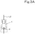
- FIG. 3A to FIG. 3C illustrate a case where the travel information of the vehicle body 3 indicates the vehicle-body position P.
- the automatic-steering control unit 40a maintains the rotational angle of the rotation shaft of the steering motor 38.
- the automatic-steering control unit 40a rotates the rotation shaft of the steering motor 38 such that the steering direction of the working vehicle 1 is oriented rightward. Specifically, if the deviation (positional deviation) between the vehicle-body position P and the planned travel line L2 is larger than or equal to the predetermined value and the working vehicle 1 is positioned to the left of the planned travel line L2, the automatic-steering control unit 40a changes the steering angle to set the positional deviation to zero, and steers the front wheels 7F rightward.
- the automatic-steering control unit 40a rotates the rotation shaft of the steering motor 38 such that the steering direction of the working vehicle 1 is oriented leftward. Specifically, if the deviation between the vehicle-body position P and the planned travel line L2 is larger than or equal to the predetermined value and the working vehicle 1 is positioned to the right of the planned travel line L2, the automatic-steering control unit 40a changes the steering angle to set the positional deviation to zero, and steers the front wheels 7F leftward.
- the travel information of the vehicle body 3 indicates the vehicle-body position P and the steering angle of the steering device 11 is changed based on the deviation between the vehicle-body position P and the planned travel line L2.
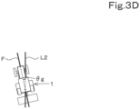
- the travel information of the vehicle body 3 may be bearing information indicating the vehicle-body bearing F.
- the automatic-steering control unit 40a defines the steering angle to set the angle ⁇ g to zero (to align the vehicle-body bearing F with the bearing of the planned travel line L2). Moreover, based on a steering angle calculated from the deviation (positional deviation) and a steering angle calculated from the bearing (bearing deviation), the automatic-steering control unit 40a may define an ultimate steering angle in the automatic steering.
- the defining method is not limited to the example described above so long as the automatic-steering control unit 40a can define the steering angle in the automatic steering.
- the following description mainly relates to a case where the travel information of the vehicle body 3 is bearing information, the reference line L1 and the planned travel line L2 are defined based on the bearings of the lines, and the automatic-steering control unit 40a defines the steering angle to set the angle ⁇ g to zero (to align the vehicle-body bearing F with the bearing of the planned travel line L2).
- the working vehicle 1 includes a mode changing switch (second operation actuator) 25 and a steering changeover switch 26.
- the mode changing switch 25 is an operable switch operation actuator that receives an operation and that is used for enabling or disabling the automatic steering, and is, for example, a push button switch.
- the mode changing switch 25 is connected to the controller 40 and can output an operation signal to the controller 40.
- the operator operates the mode changing switch 25 when enabling or disabling the automatic steering.
- the mode changing switch 25 is turned on, the controller 40 enables the automatic steering and allows the automatic-steering control unit 40a to perform the automatic steering.
- the mode changing switch 25 is turned off, the controller 40 disables the automatic steering and restricts the automatic steering by the automatic-steering control unit 40a.
- the steering changeover switch 26 is an operable switch used for starting the automatic steering (setting the automatic steering) and for terminating the automatic steering (canceling the automatic steering).
- the steering changeover switch 26 is a tiltable lever switch.
- the steering changeover switch 26 is connected to the controller 40 and can output an operation signal to the controller 40.
- the automatic-steering control unit 40a When the automatic steering is enabled, that is, when the mode changing switch 25 is turned on, the automatic-steering control unit 40a performs control for starting or terminating the automatic steering based on an operation performed on the steering changeover switch 26.
- the operator operates the steering changeover switch 26 (for starting the automatic steering) when causing the working vehicle 1 to perform the automatic steering.
- the steering changeover switch 26 can be used for canceling the automatic steering by being operated (for terminating the automatic steering) in a state where the automatic-steering control unit 40a is performing the automatic steering.
- the controller 40 has a line defining unit 40b.
- the line defining unit 40b includes electric and electronic component(s) provided in the controller 40 and/or program(s) installed in the memory unit 41.
- the line defining unit 40b defines the reference line L1 based on travel information (e.g., bearing information) of the vehicle body 3 when the vehicle body 3 is performing the manual steering.
- travel information e.g., bearing information
- the line defining unit 40b defines a predetermined start point Ps and a predetermined goal point Pg so as to define bearing information of a line extending through the start point Ps and the goal point Pg as the reference line L1.
- the line defining unit 40b defines a bearing indicating the reference line L1.
- the line defining unit 40b stores the defined reference line L1 in the memory unit 41.
- the line defining unit 40b defines positional information of a line extending through the start point Ps and the goal point Pg as the reference line L1.
- the working vehicle 1 includes a registration switch 27.
- the line defining unit 40b acquires the start point Ps and the goal point Pg of the reference line L1 in an agricultural field G and defines the reference line L1 based on the acquired start point Ps and goal point Pg.
- the registration switch 27 is an operable switch operation actuator and is, for example, a push button switch.
- the registration switch 27 may be operable by using an operation lever shared with the steering changeover switch 26.
- the registration switch 27 is connected to the controller 40 and can output an operation signal to the controller 40.
- the operator operates the registration switch 27 when defining the reference line L1.
- the line defining unit 40b can define the start point Ps and the goal point Pg based on an operation performed on the registration switch 27.
- the line defining unit 40b acquires bearing information of the vehicle body 3 at the start point Ps and the goal point Pg from the bearing (bearing information) of the working vehicle 1 when the registration switch 27 is operated.
- the line defining unit 40b calculates, for example, an average of the bearing at the start point Ps and the bearing at the goal point Pg and registers the bearing of the reference line L1, thereby defining the reference line L1.
- the line defining unit 40b acquires the start point Ps and the goal point Pg from the position (vehicle-body position P) of the working vehicle 1 when the registration switch 27 is operated, and registers the acquired start point Ps and goal point Pg, thereby defining the reference line L1.
- the line defining unit 40b can define the planned travel line L2 extending parallel to the reference line L1 based on the reference line L1 stored in the memory unit 41.
- the line defining unit 40b defines the planned travel line L2 in accordance with an operation performed on the steering changeover switch 26.
- the line defining unit 40b defines the planned travel line L2 indicating the same bearing as the bearing of the reference line L1 based on the bearing of the reference line L 1 with reference to a current vehicle-body position P (start point Ps') where the steering changeover switch 26 is operated.
- a goal point Pg' for the planned travel line L2 is a position where the steering changeover switch 26 is operated (for terminating the automatic steering).
- the line defining unit 40b acquires a current vehicle-body position P where the steering changeover switch 26 is operated.
- the line defining unit 40b sets the current vehicle-body position P as a start point Ps' and defines the planned travel line L2 by parallel-shifting the reference line L1 based on the start point Ps' and the start point Ps for the reference line L1.
- the controller 40 may be capable of transmitting the reference line L1 defined by the line defining unit 40b to the server 50, to be described below, via the communicator 42. Furthermore, if the line defining unit 40b can acquire the reference line L1 from the outside, the line defining unit 40b may be incapable of defining the reference line L1 so long as the line defining unit 40b can define the planned travel line L2 based on the reference line L1 stored in the memory unit 41.
- the communicator 42 can receive, from the server 50, a replacement line L4 for replacing the reference line L1 of the controller 40.
- the server 50 is a stationary terminal, such as a stationary computer, provided outside the working vehicle 1. Furthermore, the server 50 is, for example, a stationary terminal set in a farming household, a farming company, an agricultural machine manufacturer, or an agricultural cooperative association.
- the server 50 transmits a replacement line L4 to the communicator 42.
- the server 50 can receive a reference line L1 transmitted from the communicator 42 and store the reference line L1.
- the server 50 can store a plurality of reference lines L1.
- the source from which a reference line L1 is acquired is not limited to the working vehicle 1 so long as the server 50 can store the reference line L1.
- the server 50 may store a reference line L1 defined via a terminal connected to the server 50 in a communicable manner or may acquire a reference line L1 stored in a storage medium and store the reference line L1 in a database 53.
- the server 50 has a server controller 51, a server communicator 52, and the database 53.
- the server controller 51 performs various types of control related to the server 50 and can store (register), for example, information received by the server communicator 52 in the database 53.
- the server controller 51 includes electric and electronic component(s) and/or program(s).
- the server communicator 52 is communicable with the communicator 42 of the working vehicle 1 and with the management terminal 60 and the portable terminal 70, to be described below.
- the server communicator 52 performs wireless communication by using a data communication network or a portable telephone communication network.
- the server communicator 52 may perform wireless communication by using, for example, Bluetooth (registered trademark) Low Energy in the Bluetooth (registered trademark) specification of the communication standard IEEE 802.15.1 series or WiFi (registered trademark) of the communication standard IEEE 802.11.n series, so long as the server communicator 52 is communicable with, for example, the working vehicle 1 (communicator 42), the management terminal 60, and the portable terminal 70.
- the database 53 is, for example, a nonvolatile memory that can store various programs and various types of information.
- the database 53 can store a reference line L1.
- the database 53 registers a reference line L1, management information as identification information for the reference line L1, and work information in association with one another.
- the management information is indicated with text and alphanumeric characters and is set for facilitating, for example, the calculation, search, and organization of the reference line L1.
- the work information is related to the work of the working vehicle 1 when the vehicle body 3 performs the manual steering, that is, when the line defining unit 40b defines a reference line L1.
- the work information includes at least one piece of information from among, for example, the agricultural field G where the working vehicle 1 performs the work, the positional information of the agricultural field G (e.g., the positional information of the outline of the agricultural field G), the information about the working vehicle 1, the information about the working device 2 used in the work by the working vehicle 1, the work content of the working device 2, and the crop to be produced in the agricultural field G.
- the server communicator 52 can extract a reference line L1 stored in the database 53 and transmit the reference line L1 as a replacement line L4 to the communicator 42.
- the server 50 may be configured to correct (overwrite) a reference line L1 stored in the database 53 based on the correction.
- the management terminal 60 is a terminal, such as a smartphone (multifunctional portable telephone), a tablet, or a personal digital assistant (PDA), or a stationary computer, such as a personal computer. In this embodiment, the management terminal 60 is described as being a terminal, such as a smartphone.
- the management terminal 60 is operated by a manager who creates a work plan for the agricultural field G or by a relatively experienced operator.
- the management terminal 60 has a first terminal controller 61, a first terminal communicator 62, a first terminal memory unit 63, and a first terminal display unit 64.
- the first terminal controller 61 performs various types of control related to the management terminal 60 and can cause, for example, the first terminal display unit 64 to display various types of information by controlling the first terminal display unit 64.
- the first terminal controller 61 includes electric and electronic component(s) and/or program(s).
- the first terminal communicator 62 is communicable with the server 50 (server communicator 52).
- the first terminal communicator 62 performs wireless communication by using a data communication network or a portable telephone communication network.
- the first terminal communicator 62 may perform wireless communication by using, for example, Bluetooth (registered trademark) Low Energy in the Bluetooth (registered trademark) specification of the communication standard IEEE 802.15.1 series or WiFi (registered trademark) of the communication standard IEEE 802.11.n series, so long as the first terminal communicator 62 is communicable with, for example, the server communicator 52.
- the first terminal memory unit 63 is a nonvolatile memory that can store various types of information.
- the first terminal memory unit 63 can store various types of information related to the management terminal 60.
- the first terminal display unit 64 can display various types of information stored in the first terminal memory unit 63 as well as information received by the first terminal communicator 62.
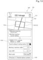
- the first terminal display unit 64 can display, for example, each of screens illustrated in FIG. 6 to FIG. 10 .
- the first terminal display unit 64 may be an input device that can receive an input of information.
- the first terminal display unit 64 is of a touchscreen type that receives an input of information in response to an operation performed by the operator by using a finger.
- the first terminal display unit 64 may be of a non-touchscreen type.
- the management terminal 60 has various switches and can receive an input of information based on an operation performed on any of the switches.
- the management terminal 60 can receive selection of any reference line L1 from reference lines L1 stored in the server 50. In detail, the management terminal 60 registers the selected reference line L1 as a candidate (candidate line L3) for a replacement line L4.
- the first terminal display unit 64 is capable of displaying (presenting) at least one reference line L 1 of the reference lines L 1 stored in the server 50.
- the management terminal 60 has a management defining unit 61a that receives selection of a reference line L1 displayed on the first terminal display unit 64 and that directly or indirectly defines a candidate line L3.
- the management defining unit 61a receives selection of any reference line L1 from reference lines L1 displayed on the first terminal display unit 64 as a candidate (candidate line L3) for a reference line L1 to be used as reference for the automatic steering by the working vehicle 1.
- the management defining unit 61a includes electric and electronic component(s) provided in the first terminal controller 61 and/or program(s) installed in the first terminal memory unit 63.
- the management defining unit 61a receives selection of any reference line L1 from the reference lines L1 and transmits the selected information (selection information) to the server 50 via the first terminal communicator 62 and the server communicator 52.
- the server 50 receives the selection information
- the server 50 defines the candidate line L3 based on the selection information.
- the management terminal 60 receives selection of any reference line L1 so as to indirectly define the candidate line L3.
- the server 50 has a first presenting unit 51a and a first setting unit 51b.
- the first presenting unit 51a and the first setting unit 51b are provided in the server controller 51 and each include electric and electronic component(s) provided in the server controller 51 and/or program(s) installed in the server controller 51.
- the first presenting unit 51a transmits the reference lines L1 stored in the server 50 to the management terminal 60 and causes the first terminal display unit 64 to display the reference lines L1 indirectly via the first terminal controller 61.
- the first setting unit 51b registers (sets) the reference line L1 corresponding to the selection information transmitted from the management defining unit 61a as the candidate line L3 from among the reference lines L1 stored in the server 50.
- the first setting unit 51b rewrites information corresponding to the selected reference line L1 so as to register the reference line L1 as the candidate line L3.
- the first setting unit 51b adds or rewrites an arbitrary text string to management information allocated to the reference line L1 so as to register the reference line L1 as the candidate line L3.
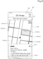
- the first presenting unit 51a causes the first terminal display unit 64 to display a screen on which work information is selectable, as illustrated in FIG. 6 and FIG. 7 , and the management defining unit 61a receives an input of the work information.
- the first presenting unit 51a causes the first terminal display unit 64 to display a first management screen M1 on which an agricultural field G is selectable as work information in step S1.
- the first management screen M1 has a first map screen 101 that displays a plurality of agricultural fields (fields) G.
- the first map screen 101 displays a bird's-eye-view map 102, outlines 103 of the agricultural fields G displayed on the map 102, and an agricultural-field information section 104 displaying information about an agricultural field G.
- Each of the outlines 103 of the agricultural fields G is a display image that is temporarily selectable in response to an operation performed on the management terminal 60.
- the agricultural-field information section 104 displays information about a temporarily selected agricultural field G (including the surface area, management number, and address of the agricultural field G).
- the agricultural-field information section 104 has an operable advance key 104a.
- the advance key 104a is an operable display image.
- the management defining unit 61a receives an operation performed on the advance key 104a so as to confirm that the agricultural field G corresponding to the temporarily selected outline 103 is selected.
- the management defining unit 61a acquires an operation signal of the outline 103 and receives selection of the agricultural field G in step S3.
- the management defining unit 61a transmits, to the server 50, information (first agricultural-field information) for identifying the selected agricultural field G in step S4.
- the first presenting unit 51a may cause the first terminal display unit 64 to display a screen to which another piece of work information is inputtable.
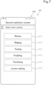
- the first presenting unit 51a causes the first terminal display unit 64 to display a second management screen M2 in step S5.
- the second management screen M2 is used for inputting the content (work content) of work to be performed by the working vehicle 1.
- the second management screen M2 displays a plurality of selectable (inputtable) first work options 111 indicating different work contents.
- the first work options 111 are a plurality of selectable display images displayed on the second management screen M2.
- the first work options 111 are respectively associated with different work contents.
- the first work options 111 displayed on the second management screen M2 correspond to "rotary (cultivating)", “ridging”, “towing”, “puddling”, “fertilizing", and “levee making”.
- the management defining unit 61a acquires an operation signal of the first work option 111 and receives an input of the work content associated with the first work option 111 in step S7.
- the management defining unit 61a transmits information (first content information) for identifying the input work content to the server 50 in step S8.
- the first presenting unit 51a extracts a reference line L1 corresponding to the work information (first agricultural-field information and first content information) received by the management defining unit 61a from the reference lines L1 stored in the database 53, and causes the first terminal display unit 64 to display a third management screen M3 based on presented information of the reference line L1 in step S9.
- the third management screen M3 has a second map screen 131 displaying an agricultural field (field) G and a candidate list 135.
- the second map screen 131 displays a bird's-eye-view map 132, a bearing guide section 132a displayed on the map 132, an outline 133 of the agricultural field G, and a first imaginary line 134.
- the first imaginary line 134 is the reference line L1 corresponding to the input work information received by the management defining unit 61a among the reference lines L1 stored in the database 53, and is displayed on the agricultural field (field) G.
- the first imaginary line 134 is the reference line L1 corresponding to the input work information (first agricultural-field information and first content information) received by the management defining unit 61a.
- the candidate list 135 displays a list of reference lines L1 corresponding to the input work information received by the management defining unit 61a.
- the candidate list 135 displays the bearing of each reference line L1, the management information, and the work information.
- a select key 135a is disposed near (e.g., to the left of) each reference line L1.
- Each select key 135a is an operable display image and is associated with the corresponding reference line L1 (first imaginary line 134).
- Each select key 135a can be used for selecting the associated reference line L1 by being operated.
- the management defining unit 61a acquires an operation signal of the relevant select key 135a and can update the first imaginary line 134 (reference line L1) displayed on the second map screen 131 of the third management screen M3.
- the candidate list 135 also has an advance key 135b.
- the advance key 135b is an operable display image, and the management defining unit 61a receives an operation (selection) performed on the advance key 135b.
- the management defining unit 61a receives an operation performed on the advance key 135b so as to receive selection of the reference line L1 corresponding to the first imaginary line 134 (first imaginary line 134 corresponding to the operated select key 135a) displayed on the second map screen 131.
- the third management screen M3 may have a refine section 136 to be selected for refining first imaginary lines 134 to be displayed in the candidate list 135.
- the management defining unit 61a acquires information about the first imaginary line 134 corresponding to the selected select key 135a and receives selection of the reference line L1 corresponding to the first imaginary line 134 in step S 11.
- the management defining unit 61a transmits selection information of the selected reference line L1 to the server 50 in step S12.
- the first presenting unit 51a causes the first terminal display unit 64 to display a fourth management screen M4 for checking the selected reference line L1 received by the management defining unit 61a from among the reference lines L1 stored in the database 53 in step S13.
- the fourth management screen M4 has a third map screen 141 displaying an agricultural field (field) G, a first details display section 145, and a check key 146.
- the third map screen 141 displays a bird's-eye-view map 142, and an outline 143 of the agricultural field G and a second imaginary line 144 that are displayed on the map 142.
- the second imaginary line 144 is any selected reference line L1 received by the management defining unit 61a and is displayed on the agricultural field (field) G.
- the first details display section 145 is an area that displays information about the selected reference line L1 received by the management defining unit 61a.
- the first details display section 145 displays work information stored in the database 53 in association with the reference line L1.
- the check key 146 is an operable display image. The check key 146 is operated for checking the selection of the reference line L1 displayed on the fourth management screen M4.
- the management defining unit 61a acquires an operation signal of the check key 146 and receives a selection check of the reference line L1 in step S15.
- the management defining unit 61a transmits checked information about the selection-checked reference line L1 to the server 50 in step S16.
- the first presenting unit 51a causes the first terminal display unit 64 to display a fifth management screen M5 for confirming the selection-checked reference line L1 received by the management defining unit 61a and the work information in step S17.
- the fifth management screen M5 has a fourth map screen 151 displaying an agricultural field (field) G, a first details input section 155, and a confirmation key 156.
- the fourth map screen 151 displays a bird's-eye-view map 152, and an outline 153 of the agricultural field G and a third imaginary line 154 that are displayed on the map 152.
- the third imaginary line 154 is any selection-checked reference line L1 received by the management defining unit 61a and is displayed on the agricultural field (field) G.
- the first details input section 155 is an area where work information to be performed along the selection-checked reference line L1 received by the management defining unit 61a is inputtable. For example, a work width and a lap width are inputtable as the work information to the first details input section 155.
- the confirmation key 156 is to be operated for confirming the selection of the reference line L1 displayed on the fifth management screen M5 and for confirming the work information input to the first details input section 155.
- the management defining unit 61a acquires an operation signal of the confirmation key 156 and receives the selection of the reference line L1 and the confirmation of the work information in step S19.
- the management defining unit 61a transmits first confirmation information about the selection-confirmed reference line L1 and the work information to the server 50 in step S20.
- the first setting unit 51b registers (sets) the selection-confirmed reference line L1 received by the management defining unit 61a as a candidate line L3 from among the reference lines L1 stored in the database 53 in step S21.
- the portable terminal 70 is a terminal, such as a smartphone (multifunctional portable telephone), a tablet, or a PDA, or a stationary computer, such as a personal computer. In this embodiment, the portable terminal 70 is described as being a terminal, such as a smartphone.
- the portable terminal 70 is independent of the management terminal 60 and is operated by, for example, an operator actually performing work on the agricultural field G. The portable terminal 70 may be operated by a relatively inexperienced operator.
- the portable terminal 70 has a second terminal controller 71, a second terminal communicator 72, a second terminal memory unit 73, and a second terminal display unit 74.
- the second terminal controller 71 performs various types of control related to the portable terminal 70 and can cause, for example, the second terminal display unit 74 to display various types of information by controlling the second terminal display unit 74.
- the second terminal controller 71 includes electric and electronic component(s) and/or program(s).
- the second terminal communicator 72 is communicable with the server 50 (server communicator 52).
- the second terminal communicator 72 performs wireless communication by using a data communication network or a portable telephone communication network.
- the second terminal communicator 72 may perform wireless communication by using, for example, Bluetooth (registered trademark) Low Energy in the Bluetooth (registered trademark) specification of the communication standard IEEE 802.15.1 series or WiFi (registered trademark) of the communication standard IEEE 802.11.n series, so long as the second terminal communicator 72 is communicable with, for example, the server communicator 52.
- the second terminal memory unit 73 is a nonvolatile memory that can store various types of information.
- the second terminal memory unit 73 can store various types of information related to the portable terminal 70.
- the second terminal display unit 74 can display various types of information stored in the second terminal memory unit 73 as well as information received by the second terminal communicator 72.
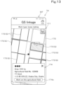
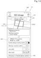
- the second terminal display unit 74 can display, for example, each of screens illustrated in FIG. 12 to FIG. 14 .
- the second terminal display unit 74 may be an input device that can receive an input of information.
- the second terminal display unit 74 is of a touchscreen type that receives an input of information in response to an operation performed by the operator by using a finger.
- the second terminal display unit 74 may be of a non-touchscreen type.
- the portable terminal 70 has various switches and can receive an input of information based on an operation performed on any of the switches.
- the portable terminal 70 can receive selection of a candidate line L3 registered by the management terminal 60 and command the server 50 to transmit the selected candidate line L3 as a replacement line L4 to the working vehicle 1.
- the portable terminal 70 receives an input of work information and extracts a candidate line L3 corresponding to the work information from the server 50, so as to receive selection of the candidate line L3.
- the portable terminal 70 has a replacement defining unit 71a that receives a process for selecting a predetermined candidate line L3 as a replacement line L4 from candidate lines L3 stored in the database 53 and that directly or indirectly defines the replacement line L4.
- the replacement defining unit 71a receives an input of work information for selecting the predetermined candidate line L3 as the replacement line L4 in response to an operation from among the candidate lines L3 stored in the database 53.
- the replacement defining unit 71a acquires work information input to the second terminal display unit 74 so as to receive an input of the work information.
- the replacement defining unit 71a includes electric and electronic component(s) provided in the second terminal controller 71 and/or program(s) installed in the second terminal memory unit 73.
- the replacement defining unit 71a transmits the received work information (input information) to the server 50.
- the server 50 extracts a candidate line L3 corresponding to the input information so as to select the candidate line L3.
- the portable terminal 70 receives an input of work information and causes the server 50 to extract a candidate line L3, so as to indirectly define the replacement line L4.
- the portable terminal 70 has a command unit 71b.
- the command unit 71b commands the server 50 to transmit a replacement line L4 to the communicator 42 in accordance with what operation is performed on the portable terminal 70.
- the command unit 71b includes electric and electronic component(s) provided in the second terminal controller 71 and/or program(s) installed in the second terminal memory unit 73.
- the command unit 71b commands the server 50 to transmit a replacement line L4 selected by the replacement defining unit 71a to the communicator 42.
- the server 50 has a second presenting unit 51c and a second setting unit 51d.
- the second presenting unit 51c and the second setting unit 51d are provided in the server controller 51 and each include electric and electronic component(s) provided in the server controller 51 and/or program(s) installed in the server controller 51.
- the second presenting unit 51c transmits the candidate lines L3 stored in the server 50 to the portable terminal 70 and causes the second terminal display unit 74 to display the candidate lines L3.
- the second setting unit 51d transmits, to the working vehicle 1, a selection-confirmed candidate line L3 received by the replacement defining unit 71a as a replacement line L4 from among the candidate lines L3 stored in the server 50.
- the second setting unit 51d transmits the replacement line L4 to the working vehicle 1 linked with the portable terminal 70 via the server communicator 52 and the communicator 42.
- the second presenting unit 51c causes the second terminal display unit 74 to display a screen to which work information is inputtable.
- the second presenting unit 51c causes the second terminal display unit 74 to display a first condition screen M6 in step S30.
- the first condition screen M6 is a screen to which work information including information about the working vehicle 1, information about the working device 2 used in work by the working vehicle 1, and information about the work content of the working device 2 is inputtable.
- the first condition screen M6 displays a second details input section 160 to which work information is inputtable.
- the second details input section 160 is an area where items of the work information are selectable.
- the second details input section 160 also has an advance key 160a.
- the advance key 160a is to be operated for confirming the work information input to the second details input section 160.
- the replacement defining unit 71a acquires the work information input to the second details input section 160 and receives an input of the work content in step S32.
- the replacement defining unit 71a transmits information (second content information) for identifying the input work content to the server 50 in step S33.
- the second presenting unit 51c may cause the second terminal display unit 74 to display a screen to which another piece of work information is inputtable.
- the second presenting unit 51c causes the first terminal display unit 64 to display a second condition screen M7 on which an agricultural field G is selectable as work information.
- the second condition screen M7 is used for selecting an agricultural field G where the working vehicle 1 performs work. As illustrated in FIG. 13 , the second condition screen M7 has a fifth map screen 171 displaying a plurality of agricultural fields (fields) G.
- the fifth map screen 171 displays a bird's-eye-view map 172, outlines 173 of the agricultural fields G displayed on the map 172, and an agricultural-field information section 174 displaying information about an agricultural field G.
- Each of the outlines 173 of the agricultural fields G is a display image that is temporarily selectable in response to an operation performed on the portable terminal 70.
- the agricultural-field information section 174 displays information about a temporarily selected agricultural field G (including the surface area, management number, and address of the agricultural field G).
- the agricultural-field information section 174 has an operable advance key 174a.
- the advance key 174a is an operable display image.
- the replacement defining unit 71a receives an operation performed on the advance key 174a so as to confirm that the agricultural field G corresponding to the temporarily selected outline 173 is selected.
- the replacement defining unit 71a acquires an operation signal of the outline 173 and receives selection of the agricultural field G in step S36.
- the replacement defining unit 71a transmits, to the server 50, information for identifying the selected agricultural field G (second agricultural-field information) in step S37.
- the replacement defining unit 71a transmits the second agricultural-field information to the server 50 in step S37
- the second presenting unit 51c causes the second terminal display unit 74 to display a confirmation screen M8 in step S38.
- the confirmation screen M8 is used for confirming selection of a candidate line L3 corresponding to input work information received by the replacement defining unit 71a from among the candidate lines L3 stored in the database 53.
- the confirmation screen M8 has a sixth map screen 181 displaying an agricultural field (field) G, a third details input section 185, and a confirmation key 186.
- the sixth map screen 181 displays a bird's-eye-view map 182, and an outline 183 of the agricultural field G and a fifth imaginary line 184 that are displayed on the map 182.
- the fifth imaginary line 184 is a candidate line L3 extracted from the database 53 by the second presenting unit 51c based on work information received by the replacement defining unit 71a, and is displayed on the agricultural field (field) G.
- the third details input section 185 is an area where work information to be performed along the candidate line L3 extracted by the second presenting unit 51c is inputtable. For example, a work width and a lap width are inputtable as the work information to the third details input section 185.
- the confirmation key 186 is to be operated for confirming the selection of the candidate line L3 displayed on the confirmation screen M8 and for confirming the work information input to the third details input section 185.
- the replacement defining unit 71a acquires an operation signal of the confirmation key 186 and receives the selection of the candidate line L3 and the confirmation of the work information in step S40.
- the command unit 71b transmits second confirmation information about the selection-confirmed candidate line L3 to the server 50, and commands the server 50 to transmit a replacement line L4 selected by the replacement defining unit 71a to the communicator 42 in step S41.
- the second setting unit 5 1d transmits, to the working vehicle 1, the selection-confirmed candidate line L3 received by the replacement defining unit 71a as a replacement line L4 from among the candidate lines L3 stored in the database 53 in step S42.
- the controller 40 When the communicator 42 receives the replacement line L4 from the server communicator 52 after step S42, the controller 40 performs a process for replacing or not replacing the reference line L1 with the replacement line L4 depending on the status of a device provided in the working vehicle 1.
- the controller 40 replaces the reference line L1 with the replacement line L4 if the status of the device satisfies a predetermined condition, and does not replace the reference line L1 with the replacement line L4 if the status of the device does not satisfy the predetermined condition.
- the condition includes, for example, the status of the controller 40, the status of the automatic steering mechanism 37, and the status of the traveling device 7.
- the controller 40 replaces the reference line L1 with the replacement line L4 if the working vehicle 1 has received the setting(s) related to the automatic steering, if the working vehicle 1 has stopped, or if the automatic steering is disabled.
- the controller 40 does not replace the reference line L1 with the replacement line L4 if the working vehicle 1 has not received the setting(s) related to the automatic steering, if the working vehicle 1 is traveling, or if the automatic steering is enabled.
- the controller 40 has a status acquiring unit 40c that acquires the status of a device provided in the working vehicle 1.
- the status acquiring unit 40c includes electric and electronic component(s) provided in the controller 40 and/or program(s) installed in the memory unit 41.
- the device status to be acquired by the status acquiring unit 40c is mainly the operational status and the control status of the device. Based on control information about control that the controller 40 is performing on the device and information input to the controller 40 from the device or various sensors, the status acquiring unit 40c acquires information about what type of operation the device is executing and what type of control the device is undergoing.
- the status acquiring unit 40c acquires control information of the display controller 21 to acquire information about whether or not the display 20 has received a change in the settings of the working vehicle 1, that is, information about whether the working vehicle 1 has received a change in the settings of the working vehicle 1, as the status of the device (controller 40).
- the status acquiring unit 40c may acquire an operation signal input to the controller 40 from the mode changing switch 25 and acquire information about whether the automatic steering by the automatic-steering control unit 40a is enabled or disabled as the status of the device (automatic steering mechanism 37).
- the status acquiring unit 40c may acquire a vehicle-speed signal input to the controller 40 from the vehicle speed sensor that detects the vehicle speed of the working vehicle 1, and acquire information about whether the working vehicle 1 is in a stopped state or is traveling as the status of the device (traveling device 7).
- the status acquiring unit 40c may acquire a control signal output from the controller 40 to the prime mover 4, and acquire information about whether or not the prime mover 4 is in an idling state as the status of the device (prime mover 4).
- the status acquiring unit 40c may acquire an operation signal input from the operation device 15 to the controller 40, and acquire information about whether or not the working vehicle 1 is operated by the operator as the status of the device (e.g., working device 2 or traveling device 7).
- the device status acquired by the status acquiring unit 40c and the acquisition method therefor described above are merely examples.
- the information to be acquired and the source from which the information is acquired are not limited to the aforementioned examples so long as the status acquiring unit 40c can acquire the status of the device provided in the working vehicle 1.
- the controller 40 switches between a first mode and a second mode in accordance with the status acquired by the status acquiring unit 40c.
- the controller 40 has a mode switch unit 40d that switches the controller 40 to the first mode or the second mode.
- the mode switch unit 40d switches the controller 40 to the first mode if the device status acquired by the status acquiring unit 40c satisfies a predetermined condition, and switches the controller 40 to the second mode if the device status does not satisfy the predetermined condition.
- the mode switch unit 40d includes electric and electronic component(s) provided in the controller 40 and/or program(s) installed in the memory unit 41.
- the first mode is a mode in which the controller 40 replaces the reference line L1 with the replacement line L4 transmitted from the server 50.
- the second mode is a mode in which the controller 40 does not replace the reference line L1 with the replacement line L4 transmitted from the server 50.
- the controller 40 When in the first mode, the controller 40 allows the communicator 42 to receive the replacement line L4 from the server 50. When the controller 40 is in the first mode and the communicator 42 receives the replacement line L4 from the server 50, the controller 40 writes the replacement line L4 over the reference line L1 stored in the memory unit 41, so that the replacement line L4 can be registered.
- the controller 40 restricts the reception of the replacement line L4 from the server 50 by the communicator 42.
- the mode switch unit 40d switches the mode of the controller 40 depending conditionally on whether or not the working vehicle 1 has received the settings related to the automatic steering.
- the mode switch unit 40d switches the controller 40 to the first mode if the working vehicle 1 has received the settings related to the automatic steering, and switches the controller 40 to the second mode if the working vehicle 1 has not received the settings related to the automatic steering.
- the working vehicle 1 has first operation actuators 221 and 251 that each receive an operation to change the setting(s) related to the automatic steering.
- the status acquiring unit 40c is configured or programmed to acquire information indicating that the first operation actuator(s) 221 and/or 251 has/have received the operation to change the setting(s) or has/have not received the operation to change the setting(s). If the status acquiring unit 40c acquires information indicating that the first operation actuator(s) 221 and/or 251 has/have received the operation to change the setting(s), the mode switch unit 40d switches the controller 40 to the first mode. On the other hand, if the status acquiring unit 40c acquires information indicating that the first operation actuator(s) 221 and/or 251 has/have not received the operation to change the setting(s), the mode switch unit 40d switches the controller 40 to the second mode.
- each of the first operation actuators 221 and 251 is an operable display image displayed on a setting check screen M10 when the display screen 22 is displaying a resetting screen M11.
- the status acquiring unit 40c acquires information about whether or not the display 20 is in a state for changing the settings related to the automatic steering, and acquires information indicating that the first operation actuator(s) 221 and/or 251 has/have received the operation to change the setting(s) or has/have not received the operation to change the setting(s).
- the first operation actuators 221 and 251 are not limited to display images displayed on the display screen 22 and may be, for example, physical switches so long as each of the first operation actuators 221 and 251 is an operation actuator for actuating a trigger related to the settings related to the automatic steering.
- the display 20 has a changer 21a that receives a change of the replacement line L4 received by the communicator 42.
- the changer 21a includes electric and electronic component(s) provided in the display controller 21 and/or program(s) installed in the memory unit 41.
- the display screen 22 is displaying a screen (setting screen M16) that receives a change of the replacement line L4
- the changer 21a receives a change of the replacement line L4 in response to an operation received by the operation member 23.
- the controller 40 can apply the change of the replacement line L4 by writing the changed replacement line L4 over the reference line L1 stored in the memory unit 41.
- the controller 40 is switched to the second mode in advance.
- the display controller 21 causes the display screen 22 to display a home screen M9 as an initial screen displayed when, for example, the display 20 is not operated for a certain period of time.
- the home screen M9 displays optional display images.
- the display controller 21 receives selection of a display image in response to an operation performed on the operation member 23.
- the home screen M9 displays a guidance key 201 and a setting key 202 as the optional display images.
- the guidance key 201 is a display image that receives a selecting operation for transition to a guidance screen (not illustrated) that provides operational guidance when the automatic steering is to be executed.
- a guidance screen not illustrated
- the guidance screen displays an operation related to the automatic steering.
- the guidance screen provides guidance for switching the automatic steering from the disabled mode to the enabled mode in response to an operation performed on the mode changing switch 25 or for starting the automatic steering (setting the automatic steering) and terminating the automatic steering (canceling the automatic steering) in response to an operation performed on the steering changeover switch 26.
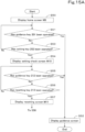
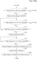
- the setting key 202 is a display image that receives, when selected, the setting check screen M10 displaying the settings related to the automatic steering. Therefore, when the display controller 21 receives a selecting operation performed on the setting key 202 (Yes in step S53), the display controller 21 causes the display screen 22 to display the setting check screen M10 in step S54.
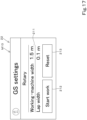
- the setting check screen M10 displays a work-information display section 211, a guidance key 212, and a resetting key 213.
- the work-information display section 211 displays work information of a reference line L1 stored in the memory unit 41.
- the display controller 21 acquires the work information of the reference line L1 stored in the memory unit 41 via the controller 40 and causes the work-information display section 211 to display the work information.
- the work-information display section 211 displays information (work content, working-machine width, and lap width) about the working device 2 used in work by the working vehicle 1 as the work information.
- the guidance key 212 is a display image that receives a selecting operation for transition to a guidance screen (not illustrated) that provides operational guidance when the automatic steering is to be executed.
- a guidance screen not illustrated
- the display controller 21 when the display controller 21 receives a selecting operation performed on the guidance key 212 in the setting check screen M10 (Yes in step S55), the display controller 21 causes the display screen 22 to display the guidance screen in step S52, similarly to the case where the selecting operation performed on the guidance key 201 in the home screen M9 is received.
- the resetting key 213 is a display image that receives, when selected, the resetting screen M11.
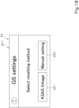
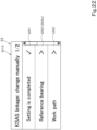
- the resetting screen M11 receives selection of a method for changing the settings related to the automatic steering.
- the display controller 21 receives a selecting operation performed on the resetting key 213 (Yes in step S56)
- the display controller 21 causes the display screen 22 to display the resetting screen M11 in step S57.
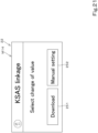
- the resetting screen M11 displays the first operation actuator (download key) 221 and a manual key 222.
- the download key 221 is a display image that receives an operation and that is used for changing the settings related to the automatic steering.
- step S58 when the display controller 21 receives a selecting operation performed on the download key 221 (Yes in step S58), the display controller 21 outputs an operation signal of the download key 221 to the controller 40 in step S59.
- the status acquiring unit 40c acquires information indicating that the download key (first operation actuator) 221 has received the operation to change the setting(s) relating to the automatic steering, based on the operation signal in step S60.
- the mode switch unit 40d switches the controller 40 to the first mode and allows the communicator 42 to receive a replacement line L4 from the server 50 in step S61.
- the display controller 21 causes the display screen 22 to display a standby screen M12 illustrated in FIG. 19 .
- the manual key 222 is a display image that receives, when selected, a command for transition from the resetting screen M11 to a manual change screen M15 to be described below.
- the display controller 21 has not received a selecting operation of the download key 221 (No in step S58)
- the display controller 21 receives a selecting operation performed on the manual key 222 (Yes in step S63)
- the display controller 21 causes the display screen 22 to display the manual change screen M15, to be described below, in step S64, as illustrated in FIG. 15C .
- the standby screen M12 is displayed on the display screen 22 until a replacement line L4 is transmitted from the server 50 to the communicator 42 when the controller 40 is in the first mode. As illustrated in FIG. 19 , the standby screen M12 displays a prompt message asking for operation of the portable terminal 70 to cause the server 50 to transmit a replacement line L4. The standby screen M12 has a cancel key 231.
- the cancel key 231 is a display image that receives, when selected, a command for transition from the standby screen M12 to the resetting screen M11. As illustrated in FIG. 15A and FIG. 15B , when the display controller 21 receives a selecting operation performed on the cancel key 231 (Yes in step S65), the display controller 21 causes the display screen 22 to display the resetting screen M11 in step S57.
- step S65 When the display controller 21 has not received a selecting operation of the cancel key 231 (No in step S65) and the communicator 42 receives a replacement line L4 from the server 50 (Yes in step S66), the mode switch unit 40d switches the controller 40 to the second mode and restricts the communicator 42 from receiving the replacement line L4 from the server 50 (step S67).
- step S68 the controller 40 registers the replacement line L4 received by the communicator 42 in step S66 as a reference line L1.
- the display controller 21 causes the display screen 22 to display a completion screen M13 illustrated in FIG. 20 in step S69.
- the completion screen M13 is a screen indicating that the replacement line L4 has been transmitted from the server 50 to the communicator 42 and that the replacement line L4 has been registered as a reference line L1.
- the completion screen M13 displays a message indicating that the replacement line L4 has been transmitted from the server 50 to the communicator 42 and that the replacement line L4 has been registered as a reference line L1.
- the completion screen M13 has a check key 241 and a change key 242.
- the check key 241 is a display image that receives, when selected, a command for transition from the completion screen M13 to the setting check screen M10.
- the display controller 21 receives a selecting operation performed on the check key 241 (Yes in step S70)
- the display controller 21 causes the display screen 22 to display the setting check screen M10 in step S54.
- the change key 242 is a display image that receives, when selected, a command for transition from the completion screen M13 to a change selection screen M14.
- the display controller 21 When the display controller 21 has not received a selecting operation of the check key 241 (No in step S70) and receives a selecting operation performed on the change key 242 (Yes in step S71), the display controller 21 causes the display screen 22 to display the change selection screen M14 in step S72.
- the change selection screen M14 is similar to the resetting screen M11 in that the change selection screen M14 displays the first operation actuator (download key) 251 and a manual key 252.
- the download key 251 is a display image that receives an operation and that is used for changing the settings related to the automatic steering.
- the display controller 21 receives a selecting operation performed on the download key 251 (Yes in step S73), the display controller 21 outputs an operation signal of the download key 251 to the controller 40 in step S74 and proceeds to step S60.
- the manual key 252 is a display image that receives, when selected, a command for transition from the change selection screen M14 to the manual change screen M15.
- the display controller 21 When the display controller 21 has not received a selecting operation of the download key 251 (No in step S73) and receives a selecting operation performed on the manual key 252 (Yes in step S75), the display controller 21 causes the display screen 22 to display the manual change screen M15 in step S64.
- the display controller 21 causes the display screen 22 to display the manual change screen M15 in step S64, as illustrated in FIG. 22 .
- the manual change screen M15 is a screen used for selecting an item to be changed from among the settings related to the automatic steering by operating the display 20.
- the manual change screen M15 has a completion key 261 and item selection keys 262.
- the completion key 261 is a display image that receives an operation and that is used for completing the settings related to the automatic steering.
- the completion key 261 is a display image that receives, when selected, a command for transition from the manual change screen M15 to the setting check screen M10.
- FIG. 15C when the display controller 21 receives a selecting operation performed on the completion key 261 (Yes in step S76), the display controller 21 causes the display screen 22 to display the setting check screen M10 in step S54.
- Each of the item selection keys 262 is a display image that receives an operation and that receives selection of a target to be changed from among the settings related to the automatic steering.
- the item selection keys 262 include a bearing change key 262a that receives selection of a change of the reference line L1 (replacement line L4).
- the display controller 21 When the display controller 21 has not received a selecting operation of the completion key 261 (No in step S76) and receives a selecting operation performed on any of the item selection keys 262 (Yes in step S77), the display controller 21 causes the display screen 22 to display a screen (setting screen M16) that receives a change in the settings in step S78, as illustrated in FIG. 23 .
- the manual change screen M15 may have at least an item selection key 262 that receives selection of a change in the setting of the reference line L1 (replacement line L4), and may have a display image that receives selection of another setting as a setting related to the automatic steering.
- the setting screen M16 receives a change in the setting of the reference line L1 (replacement line L4).
- FIG. 23 illustrates the setting screen M16 displayed by the display controller 21 when the bearing change key 262a is selected from the item selection keys 262. As illustrated in FIG. 23 , the setting screen M16 has a line display section 271, a line input section 272, and a confirmation key 273.
- the line display section 271 is a display image displaying a reference line L1 stored in the memory unit 41.
- a reference line L1 is defined using a bearing indicating the reference line L1
- the line display section 271 displays the reference line L1 with a bearing angle.
- the line display section 271 displays the reference line L1 stored in the memory unit 41, if the reference line L1 is an updated reference line L1 obtained by replacing the refence line L1 with the replacement line L4, it may be regarded that the display 20 displays the replacement line L4 in the line display section 271.
- the line input section 272 receives a change of the reference line L1 stored in the memory unit 41 in response to an operation received by the operation member 23.
- a reference line L1 is defined using a bearing indicating the reference line L1
- the line input section 272 receives a change of the reference line L1 by receiving an input of a bearing angle.
- the line input section 272 displays the reference line L1 stored in the memory unit 41 as an initial value and changes the display of the bearing angle in response to an operation performed on the operation member 23.
- the line input section 272 since the line input section 272 receives a change of the reference line L1 stored in the memory unit 41, if the reference line L1 is an updated reference line L1 obtained by replacing the reference line L1 with the replacement line L4, it may be regarded that the line input section 272 receives a change of the replacement line L4.
- the input method is not limited to the above-described method so long as the line input section 272 is capable of receiving a change of the reference line L1 stored in the memory unit 41 in response to an operation received by the operation member 23.
- the confirmation key 273 is a display image that receives an operation and that receives confirmation of a change of the input reference line L1 received by the line input section 272.
- the changer 21a receives a change of the reference line L1 in step S80.
- the changer 21a outputs, to the controller 40, information (change information) related to the change of the reference line L1 received by the line input section 272.
- the controller 40 writes the changed reference line L1 received by the changer 21a over the reference line L1 (replacement line L4) stored in the memory unit 41 based on the change information, thereby applying the change of the reference line L1 (replacement line L4) in step S82.
- the display controller 21 causes the display screen 22 to display the manual change screen M15 in step S64.
- the mode switch unit 40d may switch the mode of the controller 40 depending conditionally on whether the automatic steering is enabled or disabled. In this case, if the status acquiring unit 40c acquires information indicating that the automatic steering is disabled by the second operation actuator 25, the mode switch unit 40d switches the controller 40 to the first mode. If the status acquiring unit 40c acquires information indicating that the automatic steering is enabled by the second operation actuator 25, the mode switch unit 40d switches the controller 40 to the second mode.
- the mode switching by the mode switch unit 40d according to a first variation and the replacement of the reference line L1 with the replacement line L4 by the working-vehicle support system S will be described below with reference to FIG. 24 .
- the controller 40 is switched to the second mode in advance.
- the status acquiring unit 40c acquires an operation signal input to the controller 40 from the mode changing switch 25 and acquires information about whether the automatic steering by the automatic-steering control unit 40a is enabled or disabled as the status of the device (automatic steering mechanism 37) in step S84.
- the mode switch unit 40d checks whether the automatic steering by the automatic-steering control unit 40a is disabled in step S85.
- the mode switch unit 40d determines that the automatic steering by the automatic-steering control unit 40a is disabled (Yes in step S85), that is, if the mode switching condition is satisfied, the mode switch unit 40d switches the controller 40 to the first mode and allows the communicator 42 to receive a replacement line L4 from the server 50 in step S86.
- the controller 40 registers the replacement line L4 received by the communicator 42 from the server 50 as a reference line L1 in step S88.
- the mode switch unit 40d determines that the automatic steering by the automatic-steering control unit 40a is enabled (No in step S85), that is, if the mode switching condition is not satisfied, the mode switch unit 40d switches the controller 40 to the second mode and restricts the reception of the replacement line L4 from the server 50 by the communicator 42 in step S89.
- the mode switch unit 40d may switch the mode of the controller 40 depending conditionally on whether the vehicle body 3 is in a stopped state or is traveling.
- the mode switch unit 40d switches the controller 40 to the first mode if the status acquiring unit 40c acquires information indicating that the vehicle body 3 has stopped traveling, and switches the controller 40 to the second mode if the status acquiring unit 40c acquires information indicating that the vehicle body 3 is traveling.
- the mode switching of the controller 40 according to a second variation and the replacement of the reference line L1 with the replacement line L4 by the working-vehicle support system S will be described below with reference to FIG. 25 .
- the controller 40 is switched to the second mode in advance.
- step S91 determines that the working vehicle 1 is in a stopped state (Yes in step S91), that is, if the mode switching condition is satisfied, the mode switch unit 40d switches the controller 40 to the first mode and allows the communicator 42 to receive a replacement line L4 from the server 50 (step S92).
- the mode switch unit 40d determines that the working vehicle 1 is traveling (No in step S91), that is, if the mode switching condition is not satisfied, the mode switch unit 40d switches the controller 40 to the second mode and restricts the communicator 42 from receiving the replacement line L4 from the server 50 (step S95).
- the mode switch unit 40d switches the controller 40 to the first mode when the working vehicle 1 is in a stopped state and switches the controller 40 to the second mode when the working vehicle 1 is traveling in the second variation described above
- the above-described mode switching of the controller 40 is merely an example. If the status acquiring unit 40c acquires information about whether the traveling speed of the working vehicle 1 is below a threshold value or above or equal to the threshold value as the status of the device (traveling device 7), for example, the mode switch unit 40d may switch the controller 40 to the first mode when the traveling speed of the working vehicle 1 is below the threshold value and may switch the controller 40 to the second mode when the traveling speed of the working vehicle 1 is above or equal to the threshold value.
- the mode switch unit 40d may switch the controller 40 to the first mode when the prime mover 4 is in an idling state and may switch the controller 40 to the second mode when the prime mover 4 is not in an idling state.
- the mode switch unit 40d may switch the controller 40 to the first mode. In contrast, if the automatic steering is enabled by the second operation actuator 25 or if the status acquiring unit 40c acquires information indicating that the working vehicle 1 is traveling, the mode switch unit 40d may switch the controller 40 to the second mode.
- the controller 40 may register the replacement line L4 received by the communicator 42 from the server 50 as a reference line L1.
- the controller 40 may retain the replacement line L4 received by the communicator 42 from the server 50 without registering the replacement line L4 as a reference line L1, and may register the retained replacement line L4 as a reference line L1 when the controller 40 enters the first mode.
- the controller 40 retains the replacement line L4 by causing the memory unit 41 to temporarily store the replacement line L4. After the controller 40 retains the replacement line L4, if the communicator 42 receives a new replacement line L4, the controller 40 deletes the retained replacement line L4.
- the mode switch unit 40d determines that the working vehicle 1 is in a stopped state (Yes in step S102), that is, if the mode switching condition is satisfied, the mode switch unit 40d switches the controller 40 to the first mode in step S103.
- the controller 40 registers the replacement line L4 received by the communicator 42 from the server 50 as a reference line L1 in step S104.
- step S102 determines that the working vehicle 1 is traveling (No in step S102), that is, if the mode switching condition is not satisfied, the mode switch unit 40d switches the controller 40 to the second mode in step S105.
- step S106 the controller 40 retains the replacement line L4 received by the communicator 42 from the server 50 without registering the replacement line L4 as a reference line L1.
- the mode switch unit 40d checks whether the working vehicle 1 is in a stopped state or is traveling in step S109.
- step S109 If the mode switch unit 40d determines that the working vehicle 1 is in a stopped state (Yes in step S109), that is, if the mode switching condition is satisfied, the mode switch unit 40d switches the controller 40 to the first mode in step S110.
- the controller 40 registers the retained replacement line L4 as a reference line L1 in step S111.
- step S109 determines that the working vehicle 1 is traveling (No in step S109), that is, if the mode switching condition is not satisfied, the mode switch unit 40d switches the controller 40 to the second mode in step S112. In step S113, the controller 40 continues to retain the retained replacement line L4 without registering the replacement line L4 as a reference line L1 in step S113.
- the third variation described above relates to an example where the mode switch unit 40d switches the mode of the controller 40 based on a predetermined condition of whether the vehicle body 3 is in a stopped state or is traveling
- the condition may also be applied in a case where, for example, the working vehicle 1 has or has not received the settings related to the automatic steering. Therefore, if the condition is based on whether or not the working vehicle 1 has received the settings related to the automatic steering, the process to be performed when there is a retained replacement line L4 may involve the display controller 21 causing the display screen 22 to display a screen (not illustrated) indicating that the retained replacement line L4 is registered as a reference line L1 in place of the standby screen M12.
- the database 53 stores a plurality of reference lines L1 (replacement lines L4) in association with positional information of respective agricultural fields G.
- the database 53 stores positional information of each agricultural field G as work information stored in association with the corresponding reference line L1.
- the communicator 42 transmits the position of the vehicle body 3 detected by the detector 43 to the server 50 in predetermined cycles.
- the server 50 has a transmitter 51e.
- the transmitter 51e transmits a replacement line L4 stored in the database 53 and corresponding to the position to the communicator 42.
- the transmitter 51e is provided in the server controller 51 and includes electric and electronic component(s) provided in the server controller 51 and/or program(s).
- the management terminal 60 has the management defining unit 61a.
- the replacement defining unit 71a may select a predetermined replacement line L4 in response to an operation from among the reference lines L1 (replacement lines L4) stored in the database 53, instead of setting a candidate line L3.
- the status acquiring unit 40c may be configured or programmed to acquire information indicating that the vehicle body 3 has stopped traveling or is traveling.
- the controller 40 may be configured or programmed to: enter the first mode if the status acquiring unit 40c acquires information indicating that the vehicle body 3 has stopped traveling; and enter the second mode if the status acquiring unit 40c acquires information indicating that the vehicle body 3 is traveling.
- the communicator 42 does not receive the replacement line L4 during the second mode, so that the controller 40 does not replace the reference line L1 with the replacement line L4. Accordingly, it is possible to eliminate or reduce the likelihood that the controller 40 will control the vehicle body 3 based on an unintended path.
- the controller (40) may be configured or programmed to: when the controller (40) is in the first mode, register, as the reference line (L1), the replacement line (L4) received by the communicator (42) from the server (50); and when the controller (40) is in the second mode, retain the replacement line (L4) received by the communicator (42) from the server (50) without registering the replacement line (L4) as the reference line (L1), and register the retained replacement line (L4) as the reference line (L1) when the controller (40) enters the first mode.
- the display 20 may include a changer 21a to change the replacement line L4 received by the communicator 42 in accordance with what operation is performed.
- the controller 40 can register a more appropriate reference line L1 based on the replacement line L4 transmitted from the server 50.
- the server 50 may include a database 53 to store a plurality of the replacement lines L4 in association with respective pieces of positional information of respective agricultural fields G, and a transmitter 51e to transmit, to the communicator 42, one of the plurality of replacement lines L4 stored in the database 53 that corresponds to the position of the vehicle body 3 transmitted from the communicator 42 in accordance with the position of the vehicle body 3.
- the controller 40 can automatically update the reference line L1 such that the reference line L1 is suitable for the work on the agricultural field G in accordance with the position of the vehicle body 3.
- the support system S may further include: a portable terminal 70 to communicate with the communicator 42 and the server 50.
- the portable terminal 70 may include a command unit 71b to command the server 50 to transmit the replacement line L4 to the communicator 42 in accordance with what operation is performed on the portable terminal 70.
- any replacement line L4 defined by the replacement defining unit 71a of the portable terminal 70 can be transmitted to the communicator 42. Accordingly, the working vehicle 1 can perform the automatic steering along the planned travel line L2 based on a more appropriate reference line L1.
Landscapes
- Life Sciences & Earth Sciences (AREA)
- Engineering & Computer Science (AREA)
- Mechanical Engineering (AREA)
- Soil Sciences (AREA)
- Environmental Sciences (AREA)
- Guiding Agricultural Machines (AREA)
- Control Of Position, Course, Altitude, Or Attitude Of Moving Bodies (AREA)
Abstract
Description
- The present invention relates to support systems for working vehicles.
- A known agricultural working machine is disclosed in
Japanese Unexamined Patent Application Publication No. 2017-123803 Patent Literature 1 includes a traveling machine body switchable between manual travel and automatic travel, and a switch for switching between the manual travel and the automatic travel. The manual travel is based on manual steering, whereas the automatic travel involves traveling based on automatic steering along a preset travel line set parallel to a reference travel line. In the agricultural working machine according toPatent Literature 1, when a right command button is operated while the agricultural working machine is traveling along a ridge, a start point for the reference travel line is set. When a left command button is operated while the agricultural working machine is traveling, a goal point for the reference travel line is set. In other words, in the agricultural working machine according toPatent Literature 1, the reference travel line is set during the manual travel before automatic steering is performed. - In the above-described technology disclosed in
Patent Literature 1, when automatic steering is to be performed in accordance with a new reference travel line or when a different agricultural working machine is made to perform automatic steering in the same agricultural field, the manual travel has to be performed again from the beginning to set the reference travel line. - A method for avoiding the manual travel would be to transmit a new reference travel line (replacement line) from an external device, such as a server, to the agricultural working machine. However, depending on the transmission timing of the replacement line, automatic steering may possibly be performed on an unintended path due to the replacement line.
- In view of the aforementioned problem, an object of the present invention is to provide a support system for a working vehicle that can prevent or reduce automatic steering on an unintended path.
- A support system for a working vehicle according to an aspect of the present invention includes: a working vehicle including a vehicle body, a controller, and a communicator, the vehicle body being operable to travel selectively under manual steering using a steering device or under automatic steering using the steering device, the controller being configured or programmed to define a planned travel line for the automatic steering based on a reference line and to control the automatic steering, the communicator being configured or programmed to receive a replacement line for replacing the reference line defined by the controller; and a server to transmit the replacement line to the communicator, wherein the controller includes a status acquiring unit to acquire a status of a device provided in or on the working vehicle, and is configured or programmed to switch between a first mode and a second mode in accordance with the status acquired by the status acquiring unit, the first mode being a mode in which the controller replaces the reference line with the replacement line transmitted from the server, the second mode being a mode in which the controller does not replace the reference line with the replacement line transmitted from the server.
- The working vehicle may include a first operation actuator to receive an operation and change a setting relating to the automatic steering. The status acquiring unit may be configured or programmed to acquire information indicating that the first operation actuator has received the operation to change the setting or has not received the operation to change the setting. The controller may be configured or programmed to; enter the first mode if the status acquiring unit acquires information indicating that the first operation actuator has received the operation to change the setting; and enter the second mode if the status acquiring unit acquires information indicating that the first operation actuator has not received the operation to change the setting.
- The working vehicle may include a second operation actuator to receive an operation and enable or disable the automatic steering. The status acquiring unit may be configured or programmed to acquire information indicating that the automatic steering is enabled or disabled by the second operation actuator. The controller may be configured or programmed to: enter the first mode if the status acquiring unit acquires information indicating that the automatic steering is disabled by the second operation actuator, and enter the second mode if the status acquiring unit acquires information indicating that the automatic steering is enabled by the second operation actuator.
- The status acquiring unit may be configured or programmed to acquire information indicating that the vehicle body has stopped traveling or is traveling. The controller may be configured or programmed to: enter the first mode if the status acquiring unit acquires information indicating that the vehicle body has stopped traveling; and enter the second mode if the status acquiring unit acquires information indicating that the vehicle body is traveling.
- The controller may be configured or programmed to: when the controller is in the first mode, allow the communicator to receive the replacement line from the server; and when the controller is in the second mode, restrict the communicator from receiving the replacement line from the server.
- The controller may be configured or programmed to: when the controller is in the first mode, register, as the reference line, the replacement line received by the communicator from the server; and when the controller is in the second mode, retain the replacement line received by the communicator from the server without registering the replacement line as the reference line, and register the retained replacement line as the reference line when the controller enters the first mode.
- The working vehicle may include a display to display the replacement line received by the communicator.
- The display may include a changer to receive a change to the replacement line received by the communicator.
- The working vehicle may include a detector to detect a position of the vehicle body. The communicator may be configured or programmed to transmit the position of the vehicle body detected by the detector to the server. The server may be operable to transmit the replacement line to the communicator in accordance with the position of the vehicle body.
- The server may include a database to store a plurality of the replacement lines in association with respective pieces of positional information of respective agricultural fields, and a transmitter to transmit, to the communicator, one of the plurality of replacement lines stored in the database that corresponds to the position of the vehicle body transmitted from the communicator in accordance with the position of the vehicle body.
- The support system may further include a portable terminal to communicate with the communicator and the server. The portable terminal may include a command unit to command the server to transmit the replacement line to the communicator in accordance with what operation is performed on the portable terminal.
- The server may include a database to store a plurality of the replacement lines. The portable terminal may include a replacement defining unit to receive a selection of one of the plurality of replacement lines stored in the database and define the replacement line. The command unit may be configured or programmed to command the server to transmit the replacement line defined by the replacement defining unit to the communicator.
- The support system for the working vehicle described above can prevent or reduce automatic steering on an unintended path.
- The above and other elements, features, steps, characteristics and advantages of the present invention will become more apparent from the following detailed description of the preferred embodiments with reference to the attached drawings.
- A more complete appreciation of preferred embodiments of the present invention and many of the attendant advantages thereof will be readily obtained as the same becomes better understood by reference to the following detailed description when considered in connection with the accompanying drawings described below.
-
FIG. 1 is an overall view of a support system for a working vehicle. -
FIG. 2 is an overall view of a tractor (working vehicle). -
FIG. 3A is a diagram explaining automatic steering. -
FIG. 3B is a diagram explaining the automatic steering. -
FIG. 3C is a diagram explaining the automatic steering. -
FIG. 3D is a diagram explaining the automatic steering. -
FIG. 4 illustrates a reference line and planned travel lines. -
FIG. 5A is a diagram explaining the definition of a candidate line and the transition of a screen displayed by a first terminal display unit. -
FIG. 5B is a diagram explaining the definition of the candidate line and the transition of the screen displayed by the first terminal display unit. -
FIG. 6 illustrates a first management screen. -
FIG. 7 illustrates a second management screen. -
FIG. 8 illustrates a third management screen. -
FIG. 9 illustrates a fourth management screen. -
FIG. 10 illustrates a fifth management screen. -
FIG. 11 illustrates the flow of a replacement line transmitted to the working vehicle and the transition of a screen displayed by a second terminal display unit. -
FIG. 12 illustrates a first condition screen. -
FIG. 13 illustrates a second condition screen. -
FIG. 14 illustrates a confirmation screen. -
FIG. 15A is a first diagram explaining mode switching of a controller and the transition of a screen displayed by a display screen. -
FIG. 15B is a second diagram explaining the mode switching of the controller and the transition of the screen displayed by the display screen. -
FIG. 15C is a third diagram explaining the mode switching of the controller and the transition of the screen displayed by the display screen. -
FIG. 16 illustrates a home screen. -
FIG. 17 illustrates a setting check screen. -
FIG. 18 illustrates a resetting screen. -
FIG. 19 illustrates a standby screen. -
FIG. 20 illustrates a completion screen. -
FIG. 21 illustrates a change selection screen. -
FIG. 22 illustrates a manual change screen. -
FIG. 23 illustrates a setting screen. -
FIG. 24 is a diagram explaining the mode switching of the controller according to a first variation. -
FIG. 25 is a diagram explaining the mode switching of the controller according to a second variation. -
FIG. 26 is a diagram explaining the replacement of the reference line with the replacement line according to a third variation. -
FIG. 27 is an overall view of the working-vehicle support system according to a fourth variation. - The preferred embodiments will now be described with reference to the accompanying drawings, wherein like reference numerals designate corresponding or identical elements throughout the various drawings. The drawings are to be viewed in an orientation in which the reference numerals are viewed correctly.
- An embodiment of the present invention will be described below with reference to the drawings.
-
FIG. 1 is an overall view of a support system for a working vehicle (hereinafter may be referred to as a "working-vehicle support system") S according to this embodiment. In the working-vehicle support system S, aserver 50 transmits a replacement line L4 to a workingvehicle 1, the workingvehicle 1 replaces a reference line L1 in accordance with the replacement line L4, and automatic steering can be performed in accordance with a planned travel line L2 based on the replacement line L4 (i.e., updated reference line L1). As illustrated inFIG. 1 , the working-vehicle support system S includes the workingvehicle 1, theserver 50, amanagement terminal 60, and aportable terminal 70. - In this embodiment, the working
vehicle 1 is a tractor. The workingvehicle 1 is not limited to a tractor and may be an agricultural machine (agricultural vehicle), such as a combine or a transplanter, or a construction machine (construction vehicle), such as a loader working machine, so long as the workingvehicle 1 has avehicle body 3 capable of traveling selectively under manual steering or automatic steering according to the planned travel line L2 based on the reference line L1. -
FIG. 2 is an overall side view of the workingvehicle 1. The tractor (working vehicle 1) will be described first with reference toFIG. 1 andFIG. 2 . In this embodiment, a direction (leftward inFIG. 2 ) that an operator sitting in an operator'sseat 10 of the workingvehicle 1 faces will be defined as a forward direction, and a direction (rightward inFIG. 2 ) opposite thereto will be defined as a rearward direction. The left (near side inFIG. 2 ) of the operator will be defined as a leftward direction, and the right (far side inFIG. 2 ) of the operator will be defined as a rightward direction. - As illustrated in
FIG. 2 , the workingvehicle 1 includes thevehicle body 3, aprime mover 4, and atransmission 5. Thevehicle body 3 has a travelingdevice 7 and is capable of traveling by using the travelingdevice 7. Thevehicle body 3 is capable of traveling in either the manual steering or the automatic steering according to the planned travel line L2 based on the reference line L1. - The traveling
device 7 hasfront wheels 7F andrear wheels 7R. Although thefront wheels 7F and therear wheels 7R are tires in the example illustrated inFIG. 2 , thefront wheels 7F and therear wheels 7R may be crawlers. - The
prime mover 4 is, for example, a diesel engine or an electric motor, and is a diesel engine in this embodiment. Thetransmission 5 is capable of changing a propulsion force of the travelingdevice 7 by switching speed stages, and is also capable of switching the travelingdevice 7 between a forward motion and a rearward motion. As illustrated inFIG. 2 , thevehicle body 3 is provided with the operator'sseat 10 where the operator sits. - The rear portion of the
vehicle body 3 is provided with acoupler 8 including a three-point linkage. A working device 2 is attachable to and detachable from thecoupler 8. By coupling the working device 2 to thecoupler 8 and driving the travelingdevice 7, the workingvehicle 1 can tow the coupled working device 2. The working device 2 is, for example, a cultivator for performing a cultivation process, a fertilizer spreader for spreading fertilizers, an agricultural chemical spreader for spreading agricultural chemicals, a harvester for performing harvesting, a mower for mowing, for example, grass, a tedder for tedding, for example, grass, a rake for raking, for example, grass, or a baler for baling, for example, grass. - The working device 2 is not limited to the above-described example so long as the working device 2 is coupled to the
coupler 8 of the workingvehicle 1 or is provided in the workingvehicle 1 and performs work. For example, if the workingvehicle 1 is a combine, the working device 2 includes a mower for mowing a crop and a thresher for performing threshing. If the workingvehicle 1 is a rice planter, the working device 2 includes a cropper for planting seedlings. - As illustrated in
FIG. 1 , the workingvehicle 1 includes acontroller 40 and amemory unit 41. Thecontroller 40 controls a traveling system and a working system in the workingvehicle 1. Thecontroller 40 includes electric and electronic component(s) and/or program(s). - The
memory unit 41 is a nonvolatile memory and can store, for example, various programs and various types of information related to the workingvehicle 1. - The
controller 40 is connected to anoperation device 15 used for operating the workingvehicle 1. Theoperation device 15 includes an accelerator member (accelerator pedal, accelerator lever) 16 provided in thevehicle body 3 and a speed-change member (shift lever, speed-change switch) 17. Theaccelerator member 16 is used by the operator for manually operating the traveling speed, that is, the vehicle speed, of the working vehicle 1 (vehicle body 3). Based on an operation signal input from theaccelerator member 16, thecontroller 40 controls the traveling speed of thevehicle body 3. In detail, thecontroller 40 controls the traveling speed of thevehicle body 3 based on an operational amount of theaccelerator member 16 and a control map preliminarily stored in thememory unit 41. - The speed-
change member 17 is used by the operator for manually operating the speed stage of thetransmission 5. Based on an operation signal input from the speed-change member 17, thecontroller 40 changes the speed stage of thetransmission 5. As an alternative to this embodiment in which thecontroller 40 changes the speed stage of thetransmission 5 based on an operation performed on the speed-change member 17, the speed-change member 17 may be configured to change the speed stage of thetransmission 5 directly without the intervention of thecontroller 40. - As illustrated in
FIG. 1 , the workingvehicle 1 includes adisplay 20 that displays information. The operator can change various settings of the workingvehicle 1 by operating thedisplay 20. Thedisplay 20 has adisplay controller 21, adisplay screen 22, and anoperation member 23. Thedisplay controller 21 performs various types of control related to thedisplay 20 and controls, for example, thedisplay screen 22 to cause thedisplay screen 22 to display various types of information. Thedisplay controller 21 includes electric and electronic component(s) and/or program(s). Thedisplay controller 21 causes thedisplay screen 22 to display information about the workingvehicle 1 acquired by thecontroller 40 or causes thedisplay screen 22 to display a guidance screen to provide operational guidance for the workingvehicle 1 to the operator. - The
display controller 21 causes thedisplay screen 22 to display, for example, a display image operable in response to an operation performed on theoperation member 23 or optional display images, and receives a change in the settings of the controller 40 (working vehicle 1). Therefore, by applying the change in the settings received by thedisplay controller 21, thecontroller 40 can change the settings of the workingvehicle 1. - The
operation member 23 is an operation actuator that receives an operation from the operator. In this embodiment, theoperation member 23 is a rotationally-operable dial switch having a plurality of switch positions. The dial switch is also operable by being pressed. Theoperation member 23 mainly receives a selecting operation of a display image by being rotated, and receives a confirming operation of the selected display image by being pressed. - Although an example where the
operation member 23 is a dial switch is described in this embodiment, theoperation member 23 is not limited to a dial switch and may have a plurality of push button switches. Furthermore, thedisplay 20 may be any device capable of receiving an operation from the operator. Thedisplay screen 22 may have a touchscreen in place of or in addition to theoperation member 23, and receive an input of information in response to an operation performed by the operator by using a finger. - As illustrated in
FIG. 1 , the workingvehicle 1 includes acommunicator 42. Thecommunicator 42 is communicable with theserver 50 to be described later. For example, thecommunicator 42 performs wireless communication by using a data communication network or a portable telephone communication network. Alternatively, thecommunicator 42 may perform wireless communication by using, for example, Bluetooth (registered trademark) Low Energy in the Bluetooth (registered trademark) specification of the communication standard IEEE 802.15.1 series or WiFi (registered trademark) of the communication standard IEEE 802.11.n series, so long as thecommunicator 42 is communicable with theserver 50. - As illustrated in
FIG. 1 , the workingvehicle 1 includes a detector (position detector) 43. Thedetector 43 is capable of detecting positional information (measured position information including the latitude and the longitude) of the workingvehicle 1 by using a satellite positioning system (positioning satellite), such as D-GPS, GPS, GLONASS, BeiDou, Galileo, or MICHIBIKI. Specifically, thedetector 43 receives a satellite signal (e.g., the position of the positioning satellite and the transmission time) transmitted from a positioning satellite and detects positional information (e.g., the latitude and the longitude) based on the satellite signal. Thedetector 43 has areceiver 44 and an inertial measurement unit (IMU) 45. Thereceiver 44 has, for example, an antenna and receives a satellite signal transmitted from a positioning satellite, and is attached to thevehicle body 3 independently of theIMU 45. In this embodiment, thereceiver 44 is attached to a rollover protection structure (ROPS) provided in thevehicle body 3. Thereceiver 44 is not limited to being attached to the ROPS so long as thereceiver 44 is capable of receiving a satellite signal transmitted from a positioning satellite. - The
IMU 45 has an accelerator sensor that detects acceleration and a gyroscope sensor that detects an angular velocity. TheIMU 45 is provided in thevehicle body 3, such as below the operator'sseat 10, and is capable of detecting a roll angle, a pitch angle, and a yaw angle of thevehicle body 3. - As illustrated in
FIG. 1 , the workingvehicle 1 includes asteering device 11. Thesteering device 11 is capable of performing a manual steering involving steering thevehicle body 3 in response to an operation performed by the operator and an automatic steering involving steering thevehicle body 3 automatically without being dependent on an operation by the operator. - The
steering device 11 has asteering wheel 30 and a steering shaft (rotation shaft) 31 that rotatably supports thesteering wheel 30. Thesteering device 11 also has an assist mechanism (power steering device) 32. Theassist mechanism 32 assists in rotating the steering shaft 31 (steering wheel 30) by using, for example, hydraulic pressure. Theassist mechanism 32 includes ahydraulic pump 33, acontrol valve 34 supplied with a hydraulic fluid delivered from thehydraulic pump 33, and asteering cylinder 35 actuated by thecontrol valve 34. Thecontrol valve 34 is, for example, a three-position switching valve switchable in response to movement of a spool, and is switched in correspondence with a steering direction (rotational direction) of the steeringshaft 31. Thesteering cylinder 35 is connected to an arm (knuckle arm) 36 that changes the orientation of thefront wheels 7F. - Accordingly, when the operator holds the
steering wheel 30 and operates thesteering wheel 30 in a first direction or a second direction opposite the first direction, the switch position and the opening of thecontrol valve 34 change in correspondence with the rotational direction of thesteering wheel 30. Therefore, thesteering cylinder 35 expands or contracts leftward or rightward depending on the switch position and the opening of thecontrol valve 34, whereby the steering direction of thefront wheels 7F can be changed. In other words, thevehicle body 3 can change its traveling direction leftward or rightward in accordance with manual steering of thesteering wheel 30. - As illustrated in
FIG. 1 , thesteering device 11 has an automatic steering mechanism 37. The automatic steering mechanism 37 performs automatic steering to cause thevehicle body 3 to travel along the planned travel line L2. The automatic steering mechanism 37 includes a steering motor 38 and agear mechanism 39. The steering motor 38 is a motor whose, for example, rotational direction, rotating speed, and rotational angle are controllable based on a vehicle-body position P. Thegear mechanism 39 includes a gear that is provided at the steeringshaft 31 and that rotates together with the steeringshaft 31, and also includes a gear that is provided at a driving shaft of the steering motor 38 and that rotates together with the driving shaft. When the driving shaft of the steering motor 38 rotates, the steeringshaft 31 rotates automatically via thegear mechanism 39, and the steering direction of thefront wheels 7F can be changed such that the vehicle-body position P is aligned with the planned travel line L2. - As an alternative to this embodiment in which the working
vehicle 1 includes thesteering device 11 having thesteering wheel 30, and uses thesteering device 11 to change the orientation of thefront wheels 7F and to change the steering direction, thevehicle body 3 may be of any type so long as the steering direction (traveling direction) is changeable in accordance with the manual steering and the automatic steering. In other words, thesteering device 11 is not limited to being configured to change the steering direction of thefront wheels 7F by using thesteering wheel 30. The mechanism for changing the traveling direction may employ a related art technology, where appropriate. - Next, automatic steering control of the
vehicle body 3 will be described. The workingvehicle 1 can acquire a predetermined reference line L1 and perform the automatic steering based on the planned travel line L2 that is parallel to the reference line L1. - As illustrated in
FIG. 1 , thecontroller 40 has an automatic-steering control unit 40a. The automatic-steering control unit 40a is provided in thecontroller 40 and includes electric and electronic component(s) provided in thecontroller 40 and/or program(s) installed in thememory unit 41. - As illustrated in
FIG. 3A to FIG. 3D , the automatic-steering control unit 40a controls the steering motor 38 of the automatic steering mechanism 37 based on travel information of thevehicle body 3 when thevehicle body 3 is performing the manual steering such that thevehicle body 3 travels along the planned travel line L2. The travel information of thevehicle body 3 is information detected by thedetector 43 and indicating the position of the vehicle body 3 (vehicle-body position P) or bearing information indicating the bearing of the vehicle body 3 (vehicle-body bearing F). The automatic-steering control unit 40a controls the steering motor 38 of the automatic steering mechanism 37 such that thevehicle body 3 travels along the planned travel line L2. When the automatic-steering control unit 40a is performing the automatic steering, the operator can change the traveling speed of thevehicle body 3 and the speed stage of thetransmission 5 by operating theaccelerator member 16 and the speed-change member 17. - The control of the automatic steering mechanism 37 by the automatic-
steering control unit 40a will be described in detail below.FIG. 3A to FIG. 3C illustrate a case where the travel information of thevehicle body 3 indicates the vehicle-body position P. As illustrated inFIG. 3A , if a deviation between the vehicle-body position P and the planned travel line L2 is smaller than a predetermined value, the automatic-steering control unit 40a maintains the rotational angle of the rotation shaft of the steering motor 38. - As illustrated in
FIG. 3B , if the deviation (positional deviation) between the vehicle-body position P and the planned travel line L2 is larger than or equal to the predetermined value and the workingvehicle 1 is positioned to the left of the planned travel line L2, the automatic-steering control unit 40a rotates the rotation shaft of the steering motor 38 such that the steering direction of the workingvehicle 1 is oriented rightward. Specifically, if the deviation (positional deviation) between the vehicle-body position P and the planned travel line L2 is larger than or equal to the predetermined value and the workingvehicle 1 is positioned to the left of the planned travel line L2, the automatic-steering control unit 40a changes the steering angle to set the positional deviation to zero, and steers thefront wheels 7F rightward. - As illustrated in
FIG. 3C , if the deviation between the vehicle-body position P and the planned travel line L2 is larger than or equal to the predetermined value and the workingvehicle 1 is positioned to the right of the planned travel line L2, the automatic-steering control unit 40a rotates the rotation shaft of the steering motor 38 such that the steering direction of the workingvehicle 1 is oriented leftward. Specifically, if the deviation between the vehicle-body position P and the planned travel line L2 is larger than or equal to the predetermined value and the workingvehicle 1 is positioned to the right of the planned travel line L2, the automatic-steering control unit 40a changes the steering angle to set the positional deviation to zero, and steers thefront wheels 7F leftward. - In
FIG. 3A to FIG. 3C , the travel information of thevehicle body 3 indicates the vehicle-body position P and the steering angle of thesteering device 11 is changed based on the deviation between the vehicle-body position P and the planned travel line L2. Alternatively, as illustrated inFIG. 3D , the travel information of thevehicle body 3 may be bearing information indicating the vehicle-body bearing F. In this case, if the bearing of the planned travel line L2 and the bearing (vehicle-body bearing) F of the traveling direction of the working vehicle 1 (vehicle body 3) are different from each other, that is, if an angle θg of the vehicle-body bearing F relative to the planned travel line L2 is larger than or equal to a predetermined value, the automatic-steering control unit 40a defines the steering angle to set the angle θg to zero (to align the vehicle-body bearing F with the bearing of the planned travel line L2). Moreover, based on a steering angle calculated from the deviation (positional deviation) and a steering angle calculated from the bearing (bearing deviation), the automatic-steering control unit 40a may define an ultimate steering angle in the automatic steering. - The defining method is not limited to the example described above so long as the automatic-
steering control unit 40a can define the steering angle in the automatic steering. The following description mainly relates to a case where the travel information of thevehicle body 3 is bearing information, the reference line L1 and the planned travel line L2 are defined based on the bearings of the lines, and the automatic-steering control unit 40a defines the steering angle to set the angle θg to zero (to align the vehicle-body bearing F with the bearing of the planned travel line L2). - As illustrated in
FIG. 1 , the workingvehicle 1 includes a mode changing switch (second operation actuator) 25 and asteering changeover switch 26. Themode changing switch 25 is an operable switch operation actuator that receives an operation and that is used for enabling or disabling the automatic steering, and is, for example, a push button switch. Themode changing switch 25 is connected to thecontroller 40 and can output an operation signal to thecontroller 40. The operator operates themode changing switch 25 when enabling or disabling the automatic steering. When themode changing switch 25 is turned on, thecontroller 40 enables the automatic steering and allows the automatic-steering control unit 40a to perform the automatic steering. When themode changing switch 25 is turned off, thecontroller 40 disables the automatic steering and restricts the automatic steering by the automatic-steering control unit 40a. - The
steering changeover switch 26 is an operable switch used for starting the automatic steering (setting the automatic steering) and for terminating the automatic steering (canceling the automatic steering). In this embodiment, thesteering changeover switch 26 is a tiltable lever switch. Thesteering changeover switch 26 is connected to thecontroller 40 and can output an operation signal to thecontroller 40. - When the automatic steering is enabled, that is, when the
mode changing switch 25 is turned on, the automatic-steering control unit 40a performs control for starting or terminating the automatic steering based on an operation performed on thesteering changeover switch 26. In this embodiment, the operator operates the steering changeover switch 26 (for starting the automatic steering) when causing the workingvehicle 1 to perform the automatic steering. Thesteering changeover switch 26 can be used for canceling the automatic steering by being operated (for terminating the automatic steering) in a state where the automatic-steering control unit 40a is performing the automatic steering. - As illustrated in
FIG. 1 , thecontroller 40 has aline defining unit 40b. Theline defining unit 40b includes electric and electronic component(s) provided in thecontroller 40 and/or program(s) installed in thememory unit 41. In a case where the automatic steering is enabled, that is, in a case where themode changing switch 25 is turned on, theline defining unit 40b defines the reference line L1 based on travel information (e.g., bearing information) of thevehicle body 3 when thevehicle body 3 is performing the manual steering. When thevehicle body 3 is performing the manual steering, theline defining unit 40b defines a predetermined start point Ps and a predetermined goal point Pg so as to define bearing information of a line extending through the start point Ps and the goal point Pg as the reference line L1. In other words, theline defining unit 40b defines a bearing indicating the reference line L1. Theline defining unit 40b stores the defined reference line L1 in thememory unit 41. - If the travel information is positional information about the vehicle-body position P, the
line defining unit 40b defines positional information of a line extending through the start point Ps and the goal point Pg as the reference line L1. - As illustrated in
FIG. 1 , the workingvehicle 1 includes aregistration switch 27. Theline defining unit 40b acquires the start point Ps and the goal point Pg of the reference line L1 in an agricultural field G and defines the reference line L1 based on the acquired start point Ps and goal point Pg. - The
registration switch 27 is an operable switch operation actuator and is, for example, a push button switch. Theregistration switch 27 may be operable by using an operation lever shared with thesteering changeover switch 26. Theregistration switch 27 is connected to thecontroller 40 and can output an operation signal to thecontroller 40. The operator operates theregistration switch 27 when defining the reference line L1. Theline defining unit 40b can define the start point Ps and the goal point Pg based on an operation performed on theregistration switch 27. - In detail, if the travel information is bearing information, the
line defining unit 40b acquires bearing information of thevehicle body 3 at the start point Ps and the goal point Pg from the bearing (bearing information) of the workingvehicle 1 when theregistration switch 27 is operated. Theline defining unit 40b calculates, for example, an average of the bearing at the start point Ps and the bearing at the goal point Pg and registers the bearing of the reference line L1, thereby defining the reference line L1. - If the travel information is positional information, the
line defining unit 40b acquires the start point Ps and the goal point Pg from the position (vehicle-body position P) of the workingvehicle 1 when theregistration switch 27 is operated, and registers the acquired start point Ps and goal point Pg, thereby defining the reference line L1. - As illustrated in
FIG. 4 , theline defining unit 40b can define the planned travel line L2 extending parallel to the reference line L1 based on the reference line L1 stored in thememory unit 41. Theline defining unit 40b defines the planned travel line L2 in accordance with an operation performed on thesteering changeover switch 26. - If the travel information is bearing information and the reference line L1 is defined based on the bearing of the reference line L1, when the operator operates the steering changeover switch 26 (for starting the automatic steering) in a state where the reference line L1 is stored in the
memory unit 41, theline defining unit 40b defines the planned travel line L2 indicating the same bearing as the bearing of the reference line L1 based on the bearing of thereference line L 1 with reference to a current vehicle-body position P (start point Ps') where thesteering changeover switch 26 is operated. A goal point Pg' for the planned travel line L2 is a position where thesteering changeover switch 26 is operated (for terminating the automatic steering). - If the travel information is positional information and the reference line L1 is defined based on the positional information at the start point Ps and the goal point Pg, when the operator operates the steering changeover switch 26 (for starting the automatic steering) in a state where the reference line L1 is stored in the
memory unit 41, theline defining unit 40b acquires a current vehicle-body position P where thesteering changeover switch 26 is operated. Theline defining unit 40b sets the current vehicle-body position P as a start point Ps' and defines the planned travel line L2 by parallel-shifting the reference line L1 based on the start point Ps' and the start point Ps for the reference line L1. - The
controller 40 may be capable of transmitting the reference line L1 defined by theline defining unit 40b to theserver 50, to be described below, via thecommunicator 42. Furthermore, if theline defining unit 40b can acquire the reference line L1 from the outside, theline defining unit 40b may be incapable of defining the reference line L1 so long as theline defining unit 40b can define the planned travel line L2 based on the reference line L1 stored in thememory unit 41. Thecommunicator 42 can receive, from theserver 50, a replacement line L4 for replacing the reference line L1 of thecontroller 40. - The
server 50 is a stationary terminal, such as a stationary computer, provided outside the workingvehicle 1. Furthermore, theserver 50 is, for example, a stationary terminal set in a farming household, a farming company, an agricultural machine manufacturer, or an agricultural cooperative association. Theserver 50 transmits a replacement line L4 to thecommunicator 42. In this embodiment, theserver 50 can receive a reference line L1 transmitted from thecommunicator 42 and store the reference line L1. Theserver 50 can store a plurality of reference lines L1. - The source from which a reference line L1 is acquired is not limited to the working
vehicle 1 so long as theserver 50 can store the reference line L1. For example, in addition to or in place of the reference line L1 transmitted from thecommunicator 42, theserver 50 may store a reference line L1 defined via a terminal connected to theserver 50 in a communicable manner or may acquire a reference line L1 stored in a storage medium and store the reference line L1 in adatabase 53. - As illustrated in
FIG. 1 , theserver 50 has aserver controller 51, aserver communicator 52, and thedatabase 53. Theserver controller 51 performs various types of control related to theserver 50 and can store (register), for example, information received by theserver communicator 52 in thedatabase 53. Theserver controller 51 includes electric and electronic component(s) and/or program(s). - For example, the
server communicator 52 is communicable with thecommunicator 42 of the workingvehicle 1 and with themanagement terminal 60 and theportable terminal 70, to be described below. Theserver communicator 52 performs wireless communication by using a data communication network or a portable telephone communication network. Alternatively, theserver communicator 52 may perform wireless communication by using, for example, Bluetooth (registered trademark) Low Energy in the Bluetooth (registered trademark) specification of the communication standard IEEE 802.15.1 series or WiFi (registered trademark) of the communication standard IEEE 802.11.n series, so long as theserver communicator 52 is communicable with, for example, the working vehicle 1 (communicator 42), themanagement terminal 60, and theportable terminal 70. - The
database 53 is, for example, a nonvolatile memory that can store various programs and various types of information. In detail, thedatabase 53 can store a reference line L1. Specifically, thedatabase 53 registers a reference line L1, management information as identification information for the reference line L1, and work information in association with one another. The management information is indicated with text and alphanumeric characters and is set for facilitating, for example, the calculation, search, and organization of the reference line L1. - The work information is related to the work of the working
vehicle 1 when thevehicle body 3 performs the manual steering, that is, when theline defining unit 40b defines a reference line L1. The work information includes at least one piece of information from among, for example, the agricultural field G where the workingvehicle 1 performs the work, the positional information of the agricultural field G (e.g., the positional information of the outline of the agricultural field G), the information about the workingvehicle 1, the information about the working device 2 used in the work by the workingvehicle 1, the work content of the working device 2, and the crop to be produced in the agricultural field G. - Therefore, the
server communicator 52 can extract a reference line L1 stored in thedatabase 53 and transmit the reference line L1 as a replacement line L4 to thecommunicator 42. - If the
controller 40 has a function for correcting a reference line L1 or if a reference line L1 is to be corrected via, for example, a terminal connected in a communicable manner to theserver 50, theserver 50 may be configured to correct (overwrite) a reference line L1 stored in thedatabase 53 based on the correction. - The
management terminal 60 is a terminal, such as a smartphone (multifunctional portable telephone), a tablet, or a personal digital assistant (PDA), or a stationary computer, such as a personal computer. In this embodiment, themanagement terminal 60 is described as being a terminal, such as a smartphone. Themanagement terminal 60 is operated by a manager who creates a work plan for the agricultural field G or by a relatively experienced operator. Themanagement terminal 60 has a firstterminal controller 61, a firstterminal communicator 62, a firstterminal memory unit 63, and a firstterminal display unit 64. The firstterminal controller 61 performs various types of control related to themanagement terminal 60 and can cause, for example, the firstterminal display unit 64 to display various types of information by controlling the firstterminal display unit 64. The firstterminal controller 61 includes electric and electronic component(s) and/or program(s). - The first
terminal communicator 62 is communicable with the server 50 (server communicator 52). The firstterminal communicator 62 performs wireless communication by using a data communication network or a portable telephone communication network. Alternatively, the firstterminal communicator 62 may perform wireless communication by using, for example, Bluetooth (registered trademark) Low Energy in the Bluetooth (registered trademark) specification of the communication standard IEEE 802.15.1 series or WiFi (registered trademark) of the communication standard IEEE 802.11.n series, so long as the firstterminal communicator 62 is communicable with, for example, theserver communicator 52. - The first
terminal memory unit 63 is a nonvolatile memory that can store various types of information. The firstterminal memory unit 63 can store various types of information related to themanagement terminal 60. - The first
terminal display unit 64 can display various types of information stored in the firstterminal memory unit 63 as well as information received by the firstterminal communicator 62. The firstterminal display unit 64 can display, for example, each of screens illustrated inFIG. 6 to FIG. 10 . The firstterminal display unit 64 may be an input device that can receive an input of information. In this case, the firstterminal display unit 64 is of a touchscreen type that receives an input of information in response to an operation performed by the operator by using a finger. The firstterminal display unit 64 may be of a non-touchscreen type. In this case, themanagement terminal 60 has various switches and can receive an input of information based on an operation performed on any of the switches. - The
management terminal 60 can receive selection of any reference line L1 from reference lines L1 stored in theserver 50. In detail, themanagement terminal 60 registers the selected reference line L1 as a candidate (candidate line L3) for a replacement line L4. The firstterminal display unit 64 is capable of displaying (presenting) at least onereference line L 1 of thereference lines L 1 stored in theserver 50. - As illustrated in
FIG. 1 , themanagement terminal 60 has amanagement defining unit 61a that receives selection of a reference line L1 displayed on the firstterminal display unit 64 and that directly or indirectly defines a candidate line L3. Themanagement defining unit 61a receives selection of any reference line L1 from reference lines L1 displayed on the firstterminal display unit 64 as a candidate (candidate line L3) for a reference line L1 to be used as reference for the automatic steering by the workingvehicle 1. Themanagement defining unit 61a includes electric and electronic component(s) provided in the firstterminal controller 61 and/or program(s) installed in the firstterminal memory unit 63. - In this embodiment, the
management defining unit 61a receives selection of any reference line L1 from the reference lines L1 and transmits the selected information (selection information) to theserver 50 via the firstterminal communicator 62 and theserver communicator 52. When theserver 50 receives the selection information, theserver 50 defines the candidate line L3 based on the selection information. In other words, in this embodiment, the management terminal 60 (management defining unit 61a) receives selection of any reference line L1 so as to indirectly define the candidate line L3. - As illustrated in
FIG. 1 , theserver 50 has afirst presenting unit 51a and afirst setting unit 51b. Thefirst presenting unit 51a and thefirst setting unit 51b are provided in theserver controller 51 and each include electric and electronic component(s) provided in theserver controller 51 and/or program(s) installed in theserver controller 51. - The
first presenting unit 51a transmits the reference lines L1 stored in theserver 50 to themanagement terminal 60 and causes the firstterminal display unit 64 to display the reference lines L1 indirectly via the firstterminal controller 61. - The
first setting unit 51b registers (sets) the reference line L1 corresponding to the selection information transmitted from themanagement defining unit 61a as the candidate line L3 from among the reference lines L1 stored in theserver 50. In detail, thefirst setting unit 51b rewrites information corresponding to the selected reference line L1 so as to register the reference line L1 as the candidate line L3. Specifically, thefirst setting unit 51b adds or rewrites an arbitrary text string to management information allocated to the reference line L1 so as to register the reference line L1 as the candidate line L3. - The flow for defining a candidate line L3 and the screen transition on the first
terminal display unit 64 will be described below with reference toFIG. 5A to FIG. 10 . As illustrated inFIG. 5A andFIG. 5B , when the operator performs a predetermined operation on themanagement terminal 60, thefirst presenting unit 51a causes the firstterminal display unit 64 to display a screen on which work information is selectable, as illustrated inFIG. 6 andFIG. 7 , and themanagement defining unit 61a receives an input of the work information. In detail, as illustrated inFIG. 5A , when the operator performs a predetermined operation on themanagement terminal 60, thefirst presenting unit 51a causes the firstterminal display unit 64 to display a first management screen M1 on which an agricultural field G is selectable as work information in step S1. - As illustrated in
FIG. 6 , the first management screen M1 has afirst map screen 101 that displays a plurality of agricultural fields (fields) G. Thefirst map screen 101 displays a bird's-eye-view map 102, outlines 103 of the agricultural fields G displayed on themap 102, and an agricultural-field information section 104 displaying information about an agricultural field G. - Each of the
outlines 103 of the agricultural fields G is a display image that is temporarily selectable in response to an operation performed on themanagement terminal 60. The agricultural-field information section 104 displays information about a temporarily selected agricultural field G (including the surface area, management number, and address of the agricultural field G). The agricultural-field information section 104 has an operable advance key 104a. The advance key 104a is an operable display image. Themanagement defining unit 61a receives an operation performed on the advance key 104a so as to confirm that the agricultural field G corresponding to the temporarily selectedoutline 103 is selected. - As illustrated in
FIG. 5A , when anyoutline 103 is operated from among theoutlines 103 of the agricultural fields G on thefirst map screen 101 and the advance key 104a is operated (Yes in step S2), themanagement defining unit 61a acquires an operation signal of theoutline 103 and receives selection of the agricultural field G in step S3. When themanagement defining unit 61a receives the selection of the agricultural field G in step S3, themanagement defining unit 61a transmits, to theserver 50, information (first agricultural-field information) for identifying the selected agricultural field G in step S4. - When the
management defining unit 61a transmits the first agricultural-field information to theserver 50 in step S4, thefirst presenting unit 51a may cause the firstterminal display unit 64 to display a screen to which another piece of work information is inputtable. In this embodiment, as illustrated inFIG. 5A , thefirst presenting unit 51a causes the firstterminal display unit 64 to display a second management screen M2 in step S5. The second management screen M2 is used for inputting the content (work content) of work to be performed by the workingvehicle 1. - As illustrated in
FIG. 7 , the second management screen M2 displays a plurality of selectable (inputtable)first work options 111 indicating different work contents. Thefirst work options 111 are a plurality of selectable display images displayed on the second management screen M2. Thefirst work options 111 are respectively associated with different work contents. In this embodiment, as illustrated inFIG. 7 , thefirst work options 111 displayed on the second management screen M2 correspond to "rotary (cultivating)", "ridging", "towing", "puddling", "fertilizing", and "levee making". - As illustrated in
FIG. 5A , when anyfirst work option 111 of thefirst work options 111 displayed on the second management screen M2 is operated (Yes in step S6), themanagement defining unit 61a acquires an operation signal of thefirst work option 111 and receives an input of the work content associated with thefirst work option 111 in step S7. When themanagement defining unit 61a receives the input of the work content in step S7, themanagement defining unit 61a transmits information (first content information) for identifying the input work content to theserver 50 in step S8. - As illustrated in
FIG. 5A , when themanagement defining unit 61a transmits the first content information to theserver 50 in step S8, thefirst presenting unit 51a extracts a reference line L1 corresponding to the work information (first agricultural-field information and first content information) received by themanagement defining unit 61a from the reference lines L1 stored in thedatabase 53, and causes the firstterminal display unit 64 to display a third management screen M3 based on presented information of the reference line L1 in step S9. - As illustrated in
FIG. 8 , the third management screen M3 has asecond map screen 131 displaying an agricultural field (field) G and acandidate list 135. Thesecond map screen 131 displays a bird's-eye-view map 132, abearing guide section 132a displayed on themap 132, anoutline 133 of the agricultural field G, and a firstimaginary line 134. - The first
imaginary line 134 is the reference line L1 corresponding to the input work information received by themanagement defining unit 61a among the reference lines L1 stored in thedatabase 53, and is displayed on the agricultural field (field) G. In detail, the firstimaginary line 134 is the reference line L1 corresponding to the input work information (first agricultural-field information and first content information) received by themanagement defining unit 61a. - The
candidate list 135 displays a list of reference lines L1 corresponding to the input work information received by themanagement defining unit 61a. Thecandidate list 135 displays the bearing of each reference line L1, the management information, and the work information. - In the
candidate list 135, a select key 135a is disposed near (e.g., to the left of) each reference line L1. Each select key 135a is an operable display image and is associated with the corresponding reference line L1 (first imaginary line 134). - Each select key 135a can be used for selecting the associated reference line L1 by being operated. The
management defining unit 61a acquires an operation signal of the relevant select key 135a and can update the first imaginary line 134 (reference line L1) displayed on thesecond map screen 131 of the third management screen M3. - The
candidate list 135 also has an advance key 135b. The advance key 135b is an operable display image, and themanagement defining unit 61a receives an operation (selection) performed on the advance key 135b. Themanagement defining unit 61a receives an operation performed on the advance key 135b so as to receive selection of the reference line L1 corresponding to the first imaginary line 134 (firstimaginary line 134 corresponding to the operated select key 135a) displayed on thesecond map screen 131. - The third management screen M3 may have a refine
section 136 to be selected for refining firstimaginary lines 134 to be displayed in thecandidate list 135. - As illustrated in
FIG. 5A andFIG. 5B , when the operator selects the advance key 135b (Yes in step S10), themanagement defining unit 61a acquires information about the firstimaginary line 134 corresponding to the selected select key 135a and receives selection of the reference line L1 corresponding to the firstimaginary line 134 instep S 11. Themanagement defining unit 61a transmits selection information of the selected reference line L1 to theserver 50 in step S12. - When the
management defining unit 61a transmits the selection information to theserver 50 in step S12, thefirst presenting unit 51a causes the firstterminal display unit 64 to display a fourth management screen M4 for checking the selected reference line L1 received by themanagement defining unit 61a from among the reference lines L1 stored in thedatabase 53 in step S13. - As illustrated in
FIG. 9 , the fourth management screen M4 has athird map screen 141 displaying an agricultural field (field) G, a firstdetails display section 145, and acheck key 146. Thethird map screen 141 displays a bird's-eye-view map 142, and anoutline 143 of the agricultural field G and a secondimaginary line 144 that are displayed on themap 142. - As illustrated in
FIG. 9 , the secondimaginary line 144 is any selected reference line L1 received by themanagement defining unit 61a and is displayed on the agricultural field (field) G. - The first
details display section 145 is an area that displays information about the selected reference line L1 received by themanagement defining unit 61a. The firstdetails display section 145 displays work information stored in thedatabase 53 in association with the reference line L1. Thecheck key 146 is an operable display image. Thecheck key 146 is operated for checking the selection of the reference line L1 displayed on the fourth management screen M4. - Therefore, as illustrated in
FIG. 5B , when thecheck key 146 is operated (Yes in step S14), themanagement defining unit 61a acquires an operation signal of thecheck key 146 and receives a selection check of the reference line L1 in step S15. Themanagement defining unit 61a transmits checked information about the selection-checked reference line L1 to theserver 50 in step S16. - When the
management defining unit 61a transmits the checked information to theserver 50 in step S16, thefirst presenting unit 51a causes the firstterminal display unit 64 to display a fifth management screen M5 for confirming the selection-checked reference line L1 received by themanagement defining unit 61a and the work information in step S17. - As illustrated in
FIG. 10 , the fifth management screen M5 has afourth map screen 151 displaying an agricultural field (field) G, a firstdetails input section 155, and aconfirmation key 156. Thefourth map screen 151 displays a bird's-eye-view map 152, and anoutline 153 of the agricultural field G and a thirdimaginary line 154 that are displayed on themap 152. - As illustrated in
FIG. 10 , the thirdimaginary line 154 is any selection-checked reference line L1 received by themanagement defining unit 61a and is displayed on the agricultural field (field) G. - The first
details input section 155 is an area where work information to be performed along the selection-checked reference line L1 received by themanagement defining unit 61a is inputtable. For example, a work width and a lap width are inputtable as the work information to the firstdetails input section 155. Theconfirmation key 156 is to be operated for confirming the selection of the reference line L1 displayed on the fifth management screen M5 and for confirming the work information input to the firstdetails input section 155. - Therefore, as illustrated in
FIG. 5B , when theconfirmation key 156 is operated (Yes in step S18), themanagement defining unit 61a acquires an operation signal of theconfirmation key 156 and receives the selection of the reference line L1 and the confirmation of the work information in step S19. Themanagement defining unit 61a transmits first confirmation information about the selection-confirmed reference line L1 and the work information to theserver 50 in step S20. - Accordingly, when the
server 50 receives the first confirmation information about the reference line L1 in step S20, thefirst setting unit 51b registers (sets) the selection-confirmed reference line L1 received by themanagement defining unit 61a as a candidate line L3 from among the reference lines L1 stored in thedatabase 53 in step S21. - The
portable terminal 70 is a terminal, such as a smartphone (multifunctional portable telephone), a tablet, or a PDA, or a stationary computer, such as a personal computer. In this embodiment, theportable terminal 70 is described as being a terminal, such as a smartphone. Theportable terminal 70 is independent of themanagement terminal 60 and is operated by, for example, an operator actually performing work on the agricultural field G. Theportable terminal 70 may be operated by a relatively inexperienced operator. Theportable terminal 70 has a secondterminal controller 71, a secondterminal communicator 72, a secondterminal memory unit 73, and a secondterminal display unit 74. The secondterminal controller 71 performs various types of control related to theportable terminal 70 and can cause, for example, the secondterminal display unit 74 to display various types of information by controlling the secondterminal display unit 74. The secondterminal controller 71 includes electric and electronic component(s) and/or program(s). - The second
terminal communicator 72 is communicable with the server 50 (server communicator 52). The secondterminal communicator 72 performs wireless communication by using a data communication network or a portable telephone communication network. Alternatively, the secondterminal communicator 72 may perform wireless communication by using, for example, Bluetooth (registered trademark) Low Energy in the Bluetooth (registered trademark) specification of the communication standard IEEE 802.15.1 series or WiFi (registered trademark) of the communication standard IEEE 802.11.n series, so long as the secondterminal communicator 72 is communicable with, for example, theserver communicator 52. - The second
terminal memory unit 73 is a nonvolatile memory that can store various types of information. The secondterminal memory unit 73 can store various types of information related to theportable terminal 70. - The second
terminal display unit 74 can display various types of information stored in the secondterminal memory unit 73 as well as information received by the secondterminal communicator 72. The secondterminal display unit 74 can display, for example, each of screens illustrated inFIG. 12 to FIG. 14 . The secondterminal display unit 74 may be an input device that can receive an input of information. In this case, the secondterminal display unit 74 is of a touchscreen type that receives an input of information in response to an operation performed by the operator by using a finger. The secondterminal display unit 74 may be of a non-touchscreen type. In this case, theportable terminal 70 has various switches and can receive an input of information based on an operation performed on any of the switches. - The
portable terminal 70 can receive selection of a candidate line L3 registered by themanagement terminal 60 and command theserver 50 to transmit the selected candidate line L3 as a replacement line L4 to the workingvehicle 1. In detail, theportable terminal 70 receives an input of work information and extracts a candidate line L3 corresponding to the work information from theserver 50, so as to receive selection of the candidate line L3. - Specifically, the
portable terminal 70 has areplacement defining unit 71a that receives a process for selecting a predetermined candidate line L3 as a replacement line L4 from candidate lines L3 stored in thedatabase 53 and that directly or indirectly defines the replacement line L4. Thereplacement defining unit 71a receives an input of work information for selecting the predetermined candidate line L3 as the replacement line L4 in response to an operation from among the candidate lines L3 stored in thedatabase 53. Thereplacement defining unit 71a acquires work information input to the secondterminal display unit 74 so as to receive an input of the work information. Thereplacement defining unit 71a includes electric and electronic component(s) provided in the secondterminal controller 71 and/or program(s) installed in the secondterminal memory unit 73. - In this embodiment, the
replacement defining unit 71a transmits the received work information (input information) to theserver 50. Theserver 50 extracts a candidate line L3 corresponding to the input information so as to select the candidate line L3. In other words, theportable terminal 70 receives an input of work information and causes theserver 50 to extract a candidate line L3, so as to indirectly define the replacement line L4. - The
portable terminal 70 has acommand unit 71b. Thecommand unit 71b commands theserver 50 to transmit a replacement line L4 to thecommunicator 42 in accordance with what operation is performed on theportable terminal 70. Thecommand unit 71b includes electric and electronic component(s) provided in the secondterminal controller 71 and/or program(s) installed in the secondterminal memory unit 73. Thecommand unit 71b commands theserver 50 to transmit a replacement line L4 selected by thereplacement defining unit 71a to thecommunicator 42. - As illustrated in
FIG. 1 , theserver 50 has asecond presenting unit 51c and asecond setting unit 51d. Thesecond presenting unit 51c and thesecond setting unit 51d are provided in theserver controller 51 and each include electric and electronic component(s) provided in theserver controller 51 and/or program(s) installed in theserver controller 51. - The
second presenting unit 51c transmits the candidate lines L3 stored in theserver 50 to theportable terminal 70 and causes the secondterminal display unit 74 to display the candidate lines L3. - The
second setting unit 51d transmits, to the workingvehicle 1, a selection-confirmed candidate line L3 received by thereplacement defining unit 71a as a replacement line L4 from among the candidate lines L3 stored in theserver 50. In detail, thesecond setting unit 51d transmits the replacement line L4 to the workingvehicle 1 linked with theportable terminal 70 via theserver communicator 52 and thecommunicator 42. - The flow for receiving selection of a candidate line L3 by the
replacement defining unit 71a and transmitting the candidate line L3 from theserver 50 to the workingvehicle 1 in response to a command from thecommand unit 71b and the screen transition on the secondterminal display unit 74 will be described below with reference toFIG. 11 to FIG. 14 . - As illustrated in
FIG. 11 , for example, when the operator performs a predetermined operation on theportable terminal 70, thesecond presenting unit 51c causes the secondterminal display unit 74 to display a screen to which work information is inputtable. In detail, thesecond presenting unit 51c causes the secondterminal display unit 74 to display a first condition screen M6 in step S30. The first condition screen M6 is a screen to which work information including information about the workingvehicle 1, information about the working device 2 used in work by the workingvehicle 1, and information about the work content of the working device 2 is inputtable. - As illustrated in
FIG. 12 , the first condition screen M6 displays a seconddetails input section 160 to which work information is inputtable. The seconddetails input section 160 is an area where items of the work information are selectable. The seconddetails input section 160 also has an advance key 160a. The advance key 160a is to be operated for confirming the work information input to the seconddetails input section 160. - As illustrated in
FIG. 11 , when the work information is input to the seconddetails input section 160 and the advance key 160a is operated (Yes in step S31), thereplacement defining unit 71a acquires the work information input to the seconddetails input section 160 and receives an input of the work content in step S32. Thereplacement defining unit 71a transmits information (second content information) for identifying the input work content to theserver 50 in step S33. - When the
replacement defining unit 71a transmits the second content information to theserver 50 in step S33, thesecond presenting unit 51c may cause the secondterminal display unit 74 to display a screen to which another piece of work information is inputtable. In this embodiment, as illustrated inFIG. 11 , in step S34, thesecond presenting unit 51c causes the firstterminal display unit 64 to display a second condition screen M7 on which an agricultural field G is selectable as work information. - The second condition screen M7 is used for selecting an agricultural field G where the working
vehicle 1 performs work. As illustrated inFIG. 13 , the second condition screen M7 has afifth map screen 171 displaying a plurality of agricultural fields (fields) G. Thefifth map screen 171 displays a bird's-eye-view map 172, outlines 173 of the agricultural fields G displayed on themap 172, and an agricultural-field information section 174 displaying information about an agricultural field G. - Each of the
outlines 173 of the agricultural fields G is a display image that is temporarily selectable in response to an operation performed on theportable terminal 70. The agricultural-field information section 174 displays information about a temporarily selected agricultural field G (including the surface area, management number, and address of the agricultural field G). The agricultural-field information section 174 has an operable advance key 174a. The advance key 174a is an operable display image. Thereplacement defining unit 71a receives an operation performed on the advance key 174a so as to confirm that the agricultural field G corresponding to the temporarily selectedoutline 173 is selected. - As illustrated in
FIG. 11 , when anyoutline 173 is operated from among theoutlines 173 of the agricultural fields G on thefifth map screen 171 and the advance key 174a is operated (Yes in step S35), thereplacement defining unit 71a acquires an operation signal of theoutline 173 and receives selection of the agricultural field G in step S36. When thereplacement defining unit 71a receives the selection of the agricultural field G in step S36, thereplacement defining unit 71a transmits, to theserver 50, information for identifying the selected agricultural field G (second agricultural-field information) in step S37. - When the
replacement defining unit 71a transmits the second agricultural-field information to theserver 50 in step S37, thesecond presenting unit 51c causes the secondterminal display unit 74 to display a confirmation screen M8 in step S38. - The confirmation screen M8 is used for confirming selection of a candidate line L3 corresponding to input work information received by the
replacement defining unit 71a from among the candidate lines L3 stored in thedatabase 53. As illustrated inFIG. 14 , the confirmation screen M8 has asixth map screen 181 displaying an agricultural field (field) G, a thirddetails input section 185, and aconfirmation key 186. Thesixth map screen 181 displays a bird's-eye-view map 182, and an outline 183 of the agricultural field G and a fifthimaginary line 184 that are displayed on themap 182. - As illustrated in
FIG. 14 , the fifthimaginary line 184 is a candidate line L3 extracted from thedatabase 53 by thesecond presenting unit 51c based on work information received by thereplacement defining unit 71a, and is displayed on the agricultural field (field) G. - The third
details input section 185 is an area where work information to be performed along the candidate line L3 extracted by thesecond presenting unit 51c is inputtable. For example, a work width and a lap width are inputtable as the work information to the thirddetails input section 185. Theconfirmation key 186 is to be operated for confirming the selection of the candidate line L3 displayed on the confirmation screen M8 and for confirming the work information input to the thirddetails input section 185. - Therefore, as illustrated in
FIG. 11 , when theconfirmation key 186 is operated (Yes in step S39), thereplacement defining unit 71a acquires an operation signal of theconfirmation key 186 and receives the selection of the candidate line L3 and the confirmation of the work information in step S40. When thereplacement defining unit 71a receives the selection of the candidate line L3 and the confirmation of the work information in step S40, thecommand unit 71b transmits second confirmation information about the selection-confirmed candidate line L3 to theserver 50, and commands theserver 50 to transmit a replacement line L4 selected by thereplacement defining unit 71a to thecommunicator 42 in step S41. - Accordingly, when the
server 50 receives the second confirmation information about the candidate line L3 in step S41, thesecond setting unit 5 1d transmits, to the workingvehicle 1, the selection-confirmed candidate line L3 received by thereplacement defining unit 71a as a replacement line L4 from among the candidate lines L3 stored in thedatabase 53 in step S42. - When the
communicator 42 receives the replacement line L4 from theserver communicator 52 after step S42, thecontroller 40 performs a process for replacing or not replacing the reference line L1 with the replacement line L4 depending on the status of a device provided in the workingvehicle 1. Thecontroller 40 replaces the reference line L1 with the replacement line L4 if the status of the device satisfies a predetermined condition, and does not replace the reference line L1 with the replacement line L4 if the status of the device does not satisfy the predetermined condition. The condition includes, for example, the status of thecontroller 40, the status of the automatic steering mechanism 37, and the status of the travelingdevice 7. For example, thecontroller 40 replaces the reference line L1 with the replacement line L4 if the workingvehicle 1 has received the setting(s) related to the automatic steering, if the workingvehicle 1 has stopped, or if the automatic steering is disabled. On the other hand, for example, thecontroller 40 does not replace the reference line L1 with the replacement line L4 if the workingvehicle 1 has not received the setting(s) related to the automatic steering, if the workingvehicle 1 is traveling, or if the automatic steering is enabled. - In detail, as illustrated in
FIG. 1 , thecontroller 40 has astatus acquiring unit 40c that acquires the status of a device provided in the workingvehicle 1. Thestatus acquiring unit 40c includes electric and electronic component(s) provided in thecontroller 40 and/or program(s) installed in thememory unit 41. The device status to be acquired by thestatus acquiring unit 40c is mainly the operational status and the control status of the device. Based on control information about control that thecontroller 40 is performing on the device and information input to thecontroller 40 from the device or various sensors, thestatus acquiring unit 40c acquires information about what type of operation the device is executing and what type of control the device is undergoing. - For example, the
status acquiring unit 40c acquires control information of thedisplay controller 21 to acquire information about whether or not thedisplay 20 has received a change in the settings of the workingvehicle 1, that is, information about whether the workingvehicle 1 has received a change in the settings of the workingvehicle 1, as the status of the device (controller 40). - The
status acquiring unit 40c may acquire an operation signal input to thecontroller 40 from themode changing switch 25 and acquire information about whether the automatic steering by the automatic-steering control unit 40a is enabled or disabled as the status of the device (automatic steering mechanism 37). - The
status acquiring unit 40c may acquire a vehicle-speed signal input to thecontroller 40 from the vehicle speed sensor that detects the vehicle speed of the workingvehicle 1, and acquire information about whether the workingvehicle 1 is in a stopped state or is traveling as the status of the device (traveling device 7). - The
status acquiring unit 40c may acquire a control signal output from thecontroller 40 to theprime mover 4, and acquire information about whether or not theprime mover 4 is in an idling state as the status of the device (prime mover 4). - The
status acquiring unit 40c may acquire an operation signal input from theoperation device 15 to thecontroller 40, and acquire information about whether or not the workingvehicle 1 is operated by the operator as the status of the device (e.g., working device 2 or traveling device 7). - The device status acquired by the
status acquiring unit 40c and the acquisition method therefor described above are merely examples. The information to be acquired and the source from which the information is acquired are not limited to the aforementioned examples so long as thestatus acquiring unit 40c can acquire the status of the device provided in the workingvehicle 1. - The
controller 40 switches between a first mode and a second mode in accordance with the status acquired by thestatus acquiring unit 40c. In detail, as illustrated inFIG. 1 , thecontroller 40 has amode switch unit 40d that switches thecontroller 40 to the first mode or the second mode. Themode switch unit 40d switches thecontroller 40 to the first mode if the device status acquired by thestatus acquiring unit 40c satisfies a predetermined condition, and switches thecontroller 40 to the second mode if the device status does not satisfy the predetermined condition. Themode switch unit 40d includes electric and electronic component(s) provided in thecontroller 40 and/or program(s) installed in thememory unit 41. The first mode is a mode in which thecontroller 40 replaces the reference line L1 with the replacement line L4 transmitted from theserver 50. The second mode is a mode in which thecontroller 40 does not replace the reference line L1 with the replacement line L4 transmitted from theserver 50. - When in the first mode, the
controller 40 allows thecommunicator 42 to receive the replacement line L4 from theserver 50. When thecontroller 40 is in the first mode and thecommunicator 42 receives the replacement line L4 from theserver 50, thecontroller 40 writes the replacement line L4 over the reference line L1 stored in thememory unit 41, so that the replacement line L4 can be registered. - On the other hand, when in the second mode, the
controller 40 restricts the reception of the replacement line L4 from theserver 50 by thecommunicator 42. - The mode switching of the
mode switch unit 40d will be described below with reference to an example where themode switch unit 40d switches the mode of thecontroller 40 depending conditionally on whether or not the workingvehicle 1 has received the settings related to the automatic steering. In this embodiment, themode switch unit 40d switches thecontroller 40 to the first mode if the workingvehicle 1 has received the settings related to the automatic steering, and switches thecontroller 40 to the second mode if the workingvehicle 1 has not received the settings related to the automatic steering. - The working
vehicle 1 hasfirst operation actuators status acquiring unit 40c is configured or programmed to acquire information indicating that the first operation actuator(s) 221 and/or 251 has/have received the operation to change the setting(s) or has/have not received the operation to change the setting(s). If thestatus acquiring unit 40c acquires information indicating that the first operation actuator(s) 221 and/or 251 has/have received the operation to change the setting(s), themode switch unit 40d switches thecontroller 40 to the first mode. On the other hand, if thestatus acquiring unit 40c acquires information indicating that the first operation actuator(s) 221 and/or 251 has/have not received the operation to change the setting(s), themode switch unit 40d switches thecontroller 40 to the second mode. - In this embodiment, each of the
first operation actuators display screen 22 is displaying a resetting screen M11. In this case, thestatus acquiring unit 40c acquires information about whether or not thedisplay 20 is in a state for changing the settings related to the automatic steering, and acquires information indicating that the first operation actuator(s) 221 and/or 251 has/have received the operation to change the setting(s) or has/have not received the operation to change the setting(s). - The
first operation actuators display screen 22 and may be, for example, physical switches so long as each of thefirst operation actuators - As illustrated in
FIG. 1 , thedisplay 20 has achanger 21a that receives a change of the replacement line L4 received by thecommunicator 42. Thechanger 21a includes electric and electronic component(s) provided in thedisplay controller 21 and/or program(s) installed in thememory unit 41. When thedisplay screen 22 is displaying a screen (setting screen M16) that receives a change of the replacement line L4, thechanger 21a receives a change of the replacement line L4 in response to an operation received by theoperation member 23. Thecontroller 40 can apply the change of the replacement line L4 by writing the changed replacement line L4 over the reference line L1 stored in thememory unit 41. - The replacement of the reference line L1 with the replacement line L4 by the working-vehicle support system S and the screen transition on the
display 20 will be described below with reference toFIG. 15A to FIG. 22 . In the initial state, thecontroller 40 is switched to the second mode in advance. - As illustrated in
FIG. 15A , in step S50, thedisplay controller 21 causes thedisplay screen 22 to display a home screen M9 as an initial screen displayed when, for example, thedisplay 20 is not operated for a certain period of time. The home screen M9 displays optional display images. Thedisplay controller 21 receives selection of a display image in response to an operation performed on theoperation member 23. As illustrated inFIG. 16 , the home screen M9 displays aguidance key 201 and a setting key 202 as the optional display images. - The
guidance key 201 is a display image that receives a selecting operation for transition to a guidance screen (not illustrated) that provides operational guidance when the automatic steering is to be executed. In other words, when thedisplay controller 21 receives a selecting operation performed on the guidance key 201 (Yes in step S51), thedisplay controller 21 displays the guidance screen in step S52. The guidance screen displays an operation related to the automatic steering. In detail, for example, the guidance screen provides guidance for switching the automatic steering from the disabled mode to the enabled mode in response to an operation performed on themode changing switch 25 or for starting the automatic steering (setting the automatic steering) and terminating the automatic steering (canceling the automatic steering) in response to an operation performed on thesteering changeover switch 26. - The setting
key 202 is a display image that receives, when selected, the setting check screen M10 displaying the settings related to the automatic steering. Therefore, when thedisplay controller 21 receives a selecting operation performed on the setting key 202 (Yes in step S53), thedisplay controller 21 causes thedisplay screen 22 to display the setting check screen M10 in step S54. - As illustrated in
FIG. 17 , the setting check screen M10 displays a work-information display section 211, aguidance key 212, and a resettingkey 213. The work-information display section 211 displays work information of a reference line L1 stored in thememory unit 41. Thedisplay controller 21 acquires the work information of the reference line L1 stored in thememory unit 41 via thecontroller 40 and causes the work-information display section 211 to display the work information. In an example illustrated inFIG. 16 , the work-information display section 211 displays information (work content, working-machine width, and lap width) about the working device 2 used in work by the workingvehicle 1 as the work information. - The
guidance key 212 is a display image that receives a selecting operation for transition to a guidance screen (not illustrated) that provides operational guidance when the automatic steering is to be executed. In other words, when thedisplay controller 21 receives a selecting operation performed on theguidance key 212 in the setting check screen M10 (Yes in step S55), thedisplay controller 21 causes thedisplay screen 22 to display the guidance screen in step S52, similarly to the case where the selecting operation performed on theguidance key 201 in the home screen M9 is received. - The resetting
key 213 is a display image that receives, when selected, the resetting screen M11. The resetting screen M11 receives selection of a method for changing the settings related to the automatic steering. When thedisplay controller 21 receives a selecting operation performed on the resetting key 213 (Yes in step S56), thedisplay controller 21 causes thedisplay screen 22 to display the resetting screen M11 in step S57. - As illustrated in
FIG. 18 , the resetting screen M11 displays the first operation actuator (download key) 221 and amanual key 222. Thedownload key 221 is a display image that receives an operation and that is used for changing the settings related to the automatic steering. - As illustrated in
FIG. 15B , when thedisplay controller 21 receives a selecting operation performed on the download key 221 (Yes in step S58), thedisplay controller 21 outputs an operation signal of thedownload key 221 to thecontroller 40 in step S59. - When the
controller 40 receives the operation signal of thedownload key 221 in step S59, thestatus acquiring unit 40c acquires information indicating that the download key (first operation actuator) 221 has received the operation to change the setting(s) relating to the automatic steering, based on the operation signal in step S60. When thestatus acquiring unit 40c acquires information indicating that the setting(s) relating to the automatic steering is/are to be changed, that is, when a mode switching condition is satisfied in step S60, themode switch unit 40d switches thecontroller 40 to the first mode and allows thecommunicator 42 to receive a replacement line L4 from theserver 50 in step S61. In step S62, thedisplay controller 21 causes thedisplay screen 22 to display a standby screen M12 illustrated inFIG. 19 . - The
manual key 222 is a display image that receives, when selected, a command for transition from the resetting screen M11 to a manual change screen M15 to be described below. In a case where thedisplay controller 21 has not received a selecting operation of the download key 221 (No in step S58), when thedisplay controller 21 receives a selecting operation performed on the manual key 222 (Yes in step S63), thedisplay controller 21 causes thedisplay screen 22 to display the manual change screen M15, to be described below, in step S64, as illustrated inFIG. 15C . - The standby screen M12 is displayed on the
display screen 22 until a replacement line L4 is transmitted from theserver 50 to thecommunicator 42 when thecontroller 40 is in the first mode. As illustrated inFIG. 19 , the standby screen M12 displays a prompt message asking for operation of theportable terminal 70 to cause theserver 50 to transmit a replacement line L4. The standby screen M12 has a cancel key 231. - The cancel key 231 is a display image that receives, when selected, a command for transition from the standby screen M12 to the resetting screen M11. As illustrated in
FIG. 15A andFIG. 15B , when thedisplay controller 21 receives a selecting operation performed on the cancel key 231 (Yes in step S65), thedisplay controller 21 causes thedisplay screen 22 to display the resetting screen M11 in step S57. - When the
display controller 21 has not received a selecting operation of the cancel key 231 (No in step S65) and thecommunicator 42 receives a replacement line L4 from the server 50 (Yes in step S66), themode switch unit 40d switches thecontroller 40 to the second mode and restricts thecommunicator 42 from receiving the replacement line L4 from the server 50 (step S67). In step S68, thecontroller 40 registers the replacement line L4 received by thecommunicator 42 in step S66 as a reference line L1. - When the
controller 40 writes the replacement line L4 over the reference line L1 and registers the replacement line L4 as a reference line L1 in step S68, thedisplay controller 21 causes thedisplay screen 22 to display a completion screen M13 illustrated inFIG. 20 in step S69. - The completion screen M13 is a screen indicating that the replacement line L4 has been transmitted from the
server 50 to thecommunicator 42 and that the replacement line L4 has been registered as a reference line L1. The completion screen M13 displays a message indicating that the replacement line L4 has been transmitted from theserver 50 to thecommunicator 42 and that the replacement line L4 has been registered as a reference line L1. The completion screen M13 has acheck key 241 and achange key 242. - The
check key 241 is a display image that receives, when selected, a command for transition from the completion screen M13 to the setting check screen M10. When thedisplay controller 21 receives a selecting operation performed on the check key 241 (Yes in step S70), thedisplay controller 21 causes thedisplay screen 22 to display the setting check screen M10 in step S54. - The
change key 242 is a display image that receives, when selected, a command for transition from the completion screen M13 to a change selection screen M14. When thedisplay controller 21 has not received a selecting operation of the check key 241 (No in step S70) and receives a selecting operation performed on the change key 242 (Yes in step S71), thedisplay controller 21 causes thedisplay screen 22 to display the change selection screen M14 in step S72. - As illustrated in
FIG. 21 , the change selection screen M14 is similar to the resetting screen M11 in that the change selection screen M14 displays the first operation actuator (download key) 251 and amanual key 252. Thedownload key 251 is a display image that receives an operation and that is used for changing the settings related to the automatic steering. When thedisplay controller 21 receives a selecting operation performed on the download key 251 (Yes in step S73), thedisplay controller 21 outputs an operation signal of thedownload key 251 to thecontroller 40 in step S74 and proceeds to step S60. - The
manual key 252 is a display image that receives, when selected, a command for transition from the change selection screen M14 to the manual change screen M15. When thedisplay controller 21 has not received a selecting operation of the download key 251 (No in step S73) and receives a selecting operation performed on the manual key 252 (Yes in step S75), thedisplay controller 21 causes thedisplay screen 22 to display the manual change screen M15 in step S64. - When the
manual key 222 on the resetting screen M11 or themanual key 252 on the change selection screen M14 is operated, thedisplay controller 21 causes thedisplay screen 22 to display the manual change screen M15 in step S64, as illustrated inFIG. 22 . The manual change screen M15 is a screen used for selecting an item to be changed from among the settings related to the automatic steering by operating thedisplay 20. The manual change screen M15 has acompletion key 261 anditem selection keys 262. Thecompletion key 261 is a display image that receives an operation and that is used for completing the settings related to the automatic steering. Thecompletion key 261 is a display image that receives, when selected, a command for transition from the manual change screen M15 to the setting check screen M10. As illustrated inFIG. 15C , when thedisplay controller 21 receives a selecting operation performed on the completion key 261 (Yes in step S76), thedisplay controller 21 causes thedisplay screen 22 to display the setting check screen M10 in step S54. - Each of the
item selection keys 262 is a display image that receives an operation and that receives selection of a target to be changed from among the settings related to the automatic steering. Theitem selection keys 262 include a bearing change key 262a that receives selection of a change of the reference line L1 (replacement line L4). When thedisplay controller 21 has not received a selecting operation of the completion key 261 (No in step S76) and receives a selecting operation performed on any of the item selection keys 262 (Yes in step S77), thedisplay controller 21 causes thedisplay screen 22 to display a screen (setting screen M16) that receives a change in the settings in step S78, as illustrated inFIG. 23 . The manual change screen M15 may have at least anitem selection key 262 that receives selection of a change in the setting of the reference line L1 (replacement line L4), and may have a display image that receives selection of another setting as a setting related to the automatic steering. - The setting screen M16 receives a change in the setting of the reference line L1 (replacement line L4).
FIG. 23 illustrates the setting screen M16 displayed by thedisplay controller 21 when the bearing change key 262a is selected from theitem selection keys 262. As illustrated inFIG. 23 , the setting screen M16 has aline display section 271, aline input section 272, and aconfirmation key 273. - The
line display section 271 is a display image displaying a reference line L1 stored in thememory unit 41. In this embodiment, since a reference line L1 is defined using a bearing indicating the reference line L1, theline display section 271 displays the reference line L1 with a bearing angle. In other words, since theline display section 271 displays the reference line L1 stored in thememory unit 41, if the reference line L1 is an updated reference line L1 obtained by replacing the refence line L1 with the replacement line L4, it may be regarded that thedisplay 20 displays the replacement line L4 in theline display section 271. - The
line input section 272 receives a change of the reference line L1 stored in thememory unit 41 in response to an operation received by theoperation member 23. In this embodiment, since a reference line L1 is defined using a bearing indicating the reference line L1, theline input section 272 receives a change of the reference line L1 by receiving an input of a bearing angle. - The
line input section 272 displays the reference line L1 stored in thememory unit 41 as an initial value and changes the display of the bearing angle in response to an operation performed on theoperation member 23. In other words, since theline input section 272 receives a change of the reference line L1 stored in thememory unit 41, if the reference line L1 is an updated reference line L1 obtained by replacing the reference line L1 with the replacement line L4, it may be regarded that theline input section 272 receives a change of the replacement line L4. - Although the
line input section 272 receives an input of a bearing angle in this embodiment, the input method is not limited to the above-described method so long as theline input section 272 is capable of receiving a change of the reference line L1 stored in thememory unit 41 in response to an operation received by theoperation member 23. - As illustrated in
FIG. 15C , theconfirmation key 273 is a display image that receives an operation and that receives confirmation of a change of the input reference line L1 received by theline input section 272. When thedisplay controller 21 receives an operation performed on the confirmation key 273 (Yes in step S79), thechanger 21a receives a change of the reference line L1 in step S80. In step S81, thechanger 21a outputs, to thecontroller 40, information (change information) related to the change of the reference line L1 received by theline input section 272. - Accordingly, the
controller 40 writes the changed reference line L1 received by thechanger 21a over the reference line L1 (replacement line L4) stored in thememory unit 41 based on the change information, thereby applying the change of the reference line L1 (replacement line L4) in step S82. When thecontroller 40 applies the change of the reference line L1 in step S82, thedisplay controller 21 causes thedisplay screen 22 to display the manual change screen M15 in step S64. - Although the above-described embodiment relates to an example where the
mode switch unit 40d switches the mode (first mode or second mode) of thecontroller 40 depending on whether or not the workingvehicle 1 has received the setting(s) related to the automatic steering with regard to the replacement of the reference line L1 with the replacement line L4 by the working-vehicle support system S, themode switch unit 40d may switch the mode of thecontroller 40 depending conditionally on whether the automatic steering is enabled or disabled. In this case, if thestatus acquiring unit 40c acquires information indicating that the automatic steering is disabled by thesecond operation actuator 25, themode switch unit 40d switches thecontroller 40 to the first mode. If thestatus acquiring unit 40c acquires information indicating that the automatic steering is enabled by thesecond operation actuator 25, themode switch unit 40d switches thecontroller 40 to the second mode. - The mode switching by the
mode switch unit 40d according to a first variation and the replacement of the reference line L1 with the replacement line L4 by the working-vehicle support system S will be described below with reference toFIG. 24 . In the initial state, thecontroller 40 is switched to the second mode in advance. - First, the
status acquiring unit 40c acquires an operation signal input to thecontroller 40 from themode changing switch 25 and acquires information about whether the automatic steering by the automatic-steering control unit 40a is enabled or disabled as the status of the device (automatic steering mechanism 37) in step S84. When thestatus acquiring unit 40c acquires the information about whether the automatic steering by the automatic-steering control unit 40a is enabled or disabled as the status of the device (automatic steering mechanism 37) in step S84, themode switch unit 40d checks whether the automatic steering by the automatic-steering control unit 40a is disabled in step S85. - If the
mode switch unit 40d determines that the automatic steering by the automatic-steering control unit 40a is disabled (Yes in step S85), that is, if the mode switching condition is satisfied, themode switch unit 40d switches thecontroller 40 to the first mode and allows thecommunicator 42 to receive a replacement line L4 from theserver 50 in step S86. - When the
communicator 42 receives the replacement line L4 from the server 50 (Yes in step S87), thecontroller 40 registers the replacement line L4 received by thecommunicator 42 from theserver 50 as a reference line L1 in step S88. - In contrast, if the
mode switch unit 40d determines that the automatic steering by the automatic-steering control unit 40a is enabled (No in step S85), that is, if the mode switching condition is not satisfied, themode switch unit 40d switches thecontroller 40 to the second mode and restricts the reception of the replacement line L4 from theserver 50 by thecommunicator 42 in step S89. - The
mode switch unit 40d may switch the mode of thecontroller 40 depending conditionally on whether thevehicle body 3 is in a stopped state or is traveling. Themode switch unit 40d switches thecontroller 40 to the first mode if thestatus acquiring unit 40c acquires information indicating that thevehicle body 3 has stopped traveling, and switches thecontroller 40 to the second mode if thestatus acquiring unit 40c acquires information indicating that thevehicle body 3 is traveling. - The mode switching of the
controller 40 according to a second variation and the replacement of the reference line L1 with the replacement line L4 by the working-vehicle support system S will be described below with reference toFIG. 25 . In the initial state, thecontroller 40 is switched to the second mode in advance. - First, the
status acquiring unit 40c acquires a vehicle speed signal input to thecontroller 40 from the vehicle speed sensor and acquires information about whether the workingvehicle 1 is in a stopped state or is traveling as the status of the device (traveling device 7) in step S90. - When the
status acquiring unit 40c acquires the information about whether the workingvehicle 1 is in a stopped state or is traveling in step S90, themode switch unit 40d checks whether the workingvehicle 1 is in a stopped state in step S91. - If the
mode switch unit 40d determines that the workingvehicle 1 is in a stopped state (Yes in step S91), that is, if the mode switching condition is satisfied, themode switch unit 40d switches thecontroller 40 to the first mode and allows thecommunicator 42 to receive a replacement line L4 from the server 50 (step S92). - When the
communicator 42 receives the replacement line L4 from the server 50 (Yes in step S93), thecontroller 40 registers the replacement line L4 received by thecommunicator 42 from theserver 50 as a reference line L1 (step S94). - In contrast, if the
mode switch unit 40d determines that the workingvehicle 1 is traveling (No in step S91), that is, if the mode switching condition is not satisfied, themode switch unit 40d switches thecontroller 40 to the second mode and restricts thecommunicator 42 from receiving the replacement line L4 from the server 50 (step S95). - Although the
mode switch unit 40d switches thecontroller 40 to the first mode when the workingvehicle 1 is in a stopped state and switches thecontroller 40 to the second mode when the workingvehicle 1 is traveling in the second variation described above, the above-described mode switching of thecontroller 40 is merely an example. If thestatus acquiring unit 40c acquires information about whether the traveling speed of the workingvehicle 1 is below a threshold value or above or equal to the threshold value as the status of the device (traveling device 7), for example, themode switch unit 40d may switch thecontroller 40 to the first mode when the traveling speed of the workingvehicle 1 is below the threshold value and may switch thecontroller 40 to the second mode when the traveling speed of the workingvehicle 1 is above or equal to the threshold value. - As another alternative, if the
status acquiring unit 40c acquires a control signal from thecontroller 40 to theprime mover 4 and acquires information about whether or not theprime mover 4 is in an idling state as the status of the device (prime mover 4), for example, themode switch unit 40d may switch thecontroller 40 to the first mode when theprime mover 4 is in an idling state and may switch thecontroller 40 to the second mode when theprime mover 4 is not in an idling state. - As another alternative, if the
status acquiring unit 40c acquires an operation signal input from theoperation device 15 to thecontroller 40 and acquires information about whether or not the workingvehicle 1 is operated by the operator as the status of the device (e.g., working device 2 or traveling device 7), for example, themode switch unit 40d may switch thecontroller 40 to the first mode when the workingvehicle 1 is operated by the operator and may switch thecontroller 40 to the second mode when the workingvehicle 1 is not operated by the operator. - The
mode switch unit 40d may switch the mode of thecontroller 40 based on a plurality of conditions, and the device status acquired by thestatus acquiring unit 40c and the mode switching conditions may be combined, where appropriate. For example, if the workingvehicle 1 receives the settings related to the automatic steering and thestatus acquiring unit 40c acquires information indicating that the workingvehicle 1 is in a stopped state, themode switch unit 40d may switch thecontroller 40 to the first mode. In contrast, if the workingvehicle 1 has not received the settings related to the automatic steering or if thestatus acquiring unit 40c acquires information indicating that the workingvehicle 1 is traveling, themode switch unit 40d may switch thecontroller 40 to the second mode. - If the automatic steering is disabled by the
second operation actuator 25 and thestatus acquiring unit 40c acquires information indicating that the workingvehicle 1 is in a stopped state, themode switch unit 40d may switch thecontroller 40 to the first mode. In contrast, if the automatic steering is enabled by thesecond operation actuator 25 or if thestatus acquiring unit 40c acquires information indicating that the workingvehicle 1 is traveling, themode switch unit 40d may switch thecontroller 40 to the second mode. - Note that the
controller 40 need only replace the reference line L1 with the replacement line L4 transmitted from theserver 50 when in the first mode and not replace the reference line L1 with the replacement line L4 transmitted from theserver 50 when in the second mode. The method of not replacing thereference line L 1 with the replacement line L4 is not limited to restricting thecommunicator 42 from receiving the replacement line L4. - For example, when in the first mode, the
controller 40 may register the replacement line L4 received by thecommunicator 42 from theserver 50 as a reference line L1. When in the second mode, thecontroller 40 may retain the replacement line L4 received by thecommunicator 42 from theserver 50 without registering the replacement line L4 as a reference line L1, and may register the retained replacement line L4 as a reference line L1 when thecontroller 40 enters the first mode. In detail, thecontroller 40 retains the replacement line L4 by causing thememory unit 41 to temporarily store the replacement line L4. After thecontroller 40 retains the replacement line L4, if thecommunicator 42 receives a new replacement line L4, thecontroller 40 deletes the retained replacement line L4. - The following description with reference to
FIG. 26 discusses the replacement of the reference line L1 with the replacement line L4 by the working-vehicle support system S according to a third variation with reference to an example where themode switch unit 40d switches the mode of thecontroller 40 depending conditionally on whether thevehicle body 3 is in a stopped state or is traveling. In the initial state, thecontroller 40 is switched to the second mode in advance. - First, the
controller 40 checks whether thecommunicator 42 has received a replacement line L4 from theserver 50 in step S100. If thecontroller 40 confirms that thecommunicator 42 has received the replacement line L4 from the server 50 (Yes in step S100), thestatus acquiring unit 40c acquires a vehicle speed signal input to thecontroller 40 from the vehicle speed sensor, and acquires information about whether the workingvehicle 1 is in a stopped state or is traveling as the status of the device (traveling device 7) in step S101. - When the
status acquiring unit 40c acquires the information about whether the workingvehicle 1 is in a stopped state or is traveling in step S101, themode switch unit 40d checks whether the workingvehicle 1 is in a stopped state in step S102. - If the
mode switch unit 40d determines that the workingvehicle 1 is in a stopped state (Yes in step S102), that is, if the mode switching condition is satisfied, themode switch unit 40d switches thecontroller 40 to the first mode in step S103. Thecontroller 40 registers the replacement line L4 received by thecommunicator 42 from theserver 50 as a reference line L1 in step S104. - In contrast, if the
mode switch unit 40d determines that the workingvehicle 1 is traveling (No in step S102), that is, if the mode switching condition is not satisfied, themode switch unit 40d switches thecontroller 40 to the second mode in step S105. In step S106, thecontroller 40 retains the replacement line L4 received by thecommunicator 42 from theserver 50 without registering the replacement line L4 as a reference line L1. - If the
controller 40 confirms that thecommunicator 42 has not received a replacement line L4 from the server 50 (No in step S100), thecontroller 40 checks whether there is a retained replacement line L4 in step S107. If there is a replacement line L4 retained in the memory unit 41 (Yes in step S107), thestatus acquiring unit 40c acquires a vehicle speed signal input to thecontroller 40 from the vehicle speed sensor and acquires information about whether the workingvehicle 1 is in a stopped state or is traveling as the status of the device (traveling device 7) in step S108. - When the
status acquiring unit 40c acquires the information about whether the workingvehicle 1 is in a stopped state or is traveling in step S108, themode switch unit 40d checks whether the workingvehicle 1 is in a stopped state or is traveling in step S109. - If the
mode switch unit 40d determines that the workingvehicle 1 is in a stopped state (Yes in step S109), that is, if the mode switching condition is satisfied, themode switch unit 40d switches thecontroller 40 to the first mode in step S110. Thecontroller 40 registers the retained replacement line L4 as a reference line L1 in step S111. - In contrast, if the
mode switch unit 40d determines that the workingvehicle 1 is traveling (No in step S109), that is, if the mode switching condition is not satisfied, themode switch unit 40d switches thecontroller 40 to the second mode in step S112. In step S113, thecontroller 40 continues to retain the retained replacement line L4 without registering the replacement line L4 as a reference line L1 in step S113. - Although the third variation described above relates to an example where the
mode switch unit 40d switches the mode of thecontroller 40 based on a predetermined condition of whether thevehicle body 3 is in a stopped state or is traveling, the condition may also be applied in a case where, for example, the workingvehicle 1 has or has not received the settings related to the automatic steering. Therefore, if the condition is based on whether or not the workingvehicle 1 has received the settings related to the automatic steering, the process to be performed when there is a retained replacement line L4 may involve thedisplay controller 21 causing thedisplay screen 22 to display a screen (not illustrated) indicating that the retained replacement line L4 is registered as a reference line L1 in place of the standby screen M12. - In each of the first to third variations described above, the
server 50 transmits a replacement line L4 to thecommunicator 42 in response to a command from thecommand unit 71b. However, if the replacement line L4 received by thecommunicator 42 from theserver 50 is to be retained without being registered as a reference line L1 when thecontroller 40 is in the second mode, as in the third variation, theserver 50 may transmit the replacement line L4 to thecommunicator 42 in accordance with the position of thevehicle body 3 regardless of a command from thecommand unit 71b. - In this case, the
database 53 stores a plurality of reference lines L1 (replacement lines L4) in association with positional information of respective agricultural fields G. In detail, thedatabase 53 stores positional information of each agricultural field G as work information stored in association with the corresponding reference line L1. - Furthermore, the
communicator 42 transmits the position of thevehicle body 3 detected by thedetector 43 to theserver 50 in predetermined cycles. - As illustrated in
FIG. 27 , theserver 50 has atransmitter 51e. In accordance with the position of thevehicle body 3 transmitted from thecommunicator 42, thetransmitter 51e transmits a replacement line L4 stored in thedatabase 53 and corresponding to the position to thecommunicator 42. Thetransmitter 51e is provided in theserver controller 51 and includes electric and electronic component(s) provided in theserver controller 51 and/or program(s). - The
transmitter 51e acquires the current vehicle-body position P of the workingvehicle 1 via theserver communicator 52 and thecommunicator 42. Based on positional information indicating the acquired vehicle-body position P, thetransmitter 51e determines which of the agricultural fields G the workingvehicle 1 is located in. Thetransmitter 51e acquires, from thedatabase 53, a reference line L1 corresponding to the agricultural field G where the workingvehicle 1 is located and corresponding to the information about the workingvehicle 1, the information about the working device 2 used in the work by the workingvehicle 1, the work content of the working device 2, and the information about the crop to be produced in the agricultural field G. Thetransmitter 51e transmits the acquired reference line L1 as a replacement line L4 to thecontroller 40 via thecommunicator 42 and theserver communicator 52. - The above-described embodiment relates to an example where the
management terminal 60 has themanagement defining unit 61a. Alternatively, instead of defining a candidate line L3 in advance in themanagement terminal 60, thereplacement defining unit 71a may select a predetermined replacement line L4 in response to an operation from among the reference lines L1 (replacement lines L4) stored in thedatabase 53, instead of setting a candidate line L3. - A support system S for a working
vehicle 1 as has been discussed includes: a workingvehicle 1 including avehicle body 3, acontroller 40, and acommunicator 42, thevehicle body 3 being operable to travel selectively under manual steering using asteering device 11 or under automatic steering using thesteering device 11, thecontroller 40 being configured or programmed to define a planned travel line L2 for the automatic steering based on a reference line L1 and to control the automatic steering, thecommunicator 42 being configured or programmed to receive a replacement line L4 for replacing the reference line L1 defined by thecontroller 40; and aserver 50 to transmit the replacement line L4 to thecommunicator 42, wherein thecontroller 40 includes astatus acquiring unit 40c to acquire a status of a device provided in or on the workingvehicle 1, and is configured or programmed to switch between a first mode and a second mode in accordance with the status acquired by thestatus acquiring unit 40c, the first mode being a mode in which thecontroller 40 replaces the reference line L1 with the replacement line L4 transmitted from theserver 50, the second mode being a mode in which thecontroller 40 does not replace the reference line L1 with the replacement line L4 transmitted from theserver 50. - With the above configuration, even when the
server 50 transmits the replacement line L4 to thecommunicator 42, thecontroller 40 in the second mode does not replace the reference line L1 with the replacement line L4 and controls the automatic steering based on the reference line L1. Accordingly, thecontroller 40 does not control the automatic steering based on the updated reference line L1 obtained by replacing the reference line L1 with the replacement line L4, thereby preventing or reducing traveling on an unintended path. - The working
vehicle 1 may include afirst operation actuator status acquiring unit 40c may be configured or programmed to acquire information indicating that thefirst operation actuator controller 40 may be configured or programmed to; enter the first mode if thestatus acquiring unit 40c acquires information indicating that thefirst operation actuator status acquiring unit 40c acquires information indicating that thefirst operation actuator - With the above configuration, if the setting relating to the automatic steering is not performed, that is, if the operator does not intend to change the settings relating to the automatic steering, the
controller 40 can eliminate or reduce the likelihood that the reference line L1 will be replaced with the received replacement line L4. - The working
vehicle 1 may include asecond operation actuator 25 to receive an operation and enable or disable the automatic steering. Thestatus acquiring unit 40c may be configured or programmed to acquire information indicating that the automatic steering is enabled or disabled by thesecond operation actuator 25. Thecontroller 40 may be configured or programmed to: enter the first mode if thestatus acquiring unit 40c acquires information indicating that the automatic steering is disabled by thesecond operation actuator 25, and enter the second mode if thestatus acquiring unit 40c acquires information indicating that the automatic steering is enabled by thesecond operation actuator 25. - With the above configuration, the
controller 40 can replace the reference line L1 with the received replacement line L4 only when the automatic steering is not performed. Therefore, when thecontroller 40 is controlling the automatic steering, the received replacement line L4 does not replace the reference line L1 during the control, thereby eliminating or reducing the likelihood that the automatic steering will be performed along an unintended path. - The
status acquiring unit 40c may be configured or programmed to acquire information indicating that thevehicle body 3 has stopped traveling or is traveling. Thecontroller 40 may be configured or programmed to: enter the first mode if thestatus acquiring unit 40c acquires information indicating that thevehicle body 3 has stopped traveling; and enter the second mode if thestatus acquiring unit 40c acquires information indicating that thevehicle body 3 is traveling. - With the above configuration, the
controller 40 can replace the reference line L1 with the received replacement line L4 only if thevehicle body 3 has stopped traveling. This makes it possible to eliminate or reduce the likelihood that thecontroller 40 will replace the reference line L1 with the replacement line L4 during travel of thevehicle body 3, i.e., at least while thecontroller 40 is controlling the automatic steering. - The
controller 40 may be configured or programmed to: when thecontroller 40 is in the first mode, allow thecommunicator 42 to receive the replacement line L4 from theserver 50; and when thecontroller 40 is in the second mode, restrict thecommunicator 42 from receiving the replacement line L4 from theserver 50. - With the above configuration, even when the
server 50 tries to transmit the replacement line L4 to thecommunicator 42, thecommunicator 42 does not receive the replacement line L4 during the second mode, so that thecontroller 40 does not replace the reference line L1 with the replacement line L4. Accordingly, it is possible to eliminate or reduce the likelihood that thecontroller 40 will control thevehicle body 3 based on an unintended path. - The controller (40) may be configured or programmed to: when the controller (40) is in the first mode, register, as the reference line (L1), the replacement line (L4) received by the communicator (42) from the server (50); and when the controller (40) is in the second mode, retain the replacement line (L4) received by the communicator (42) from the server (50) without registering the replacement line (L4) as the reference line (L1), and register the retained replacement line (L4) as the reference line (L1) when the controller (40) enters the first mode.
- With the above configuration, even when the
server 50 tries to transmit the replacement line L4 to thecommunicator 42, thecontroller 40 in the second mode does not register the replacement line L4. Moreover, upon switching to the first mode, thecontroller 40 can register the retained replacement line L4. With this, it is possible to eliminate or reduce the likelihood that thecontroller 40 will control thevehicle body 3 based an unintended path, and, by causing thecontroller 40 to pre-receive the replacement line L4 while in the second mode, possible to cause thecontroller 40 to efficiently register the replacement line L4 upon switching to the first mode. - The working
vehicle 1 may include adisplay 20 to display the replacement line L4 received by thecommunicator 42. - With the above configuration, by checking the
display 20, the operator can easily know whether or not the replacement line L4 is an intended line. - The
display 20 may include achanger 21a to change the replacement line L4 received by thecommunicator 42 in accordance with what operation is performed. - With the above configuration, the operator can operate the
display 20 to change the replacement line L4. Therefore, thecontroller 40 can register a more appropriate reference line L1 based on the replacement line L4 transmitted from theserver 50. - The working
vehicle 1 may include adetector 43 to detect a position of thevehicle body 3. Thecommunicator 42 may be configured or programmed to transmit the position of thevehicle body 3 detected by thedetector 43 to theserver 50. Theserver 50 may be operable to transmit the replacement line L4 to thecommunicator 42 in accordance with the position of thevehicle body 3. - With the above configuration, the
controller 40 can automatically update the reference line L1 in accordance with the position of thevehicle body 3. - The
server 50 may include adatabase 53 to store a plurality of the replacement lines L4 in association with respective pieces of positional information of respective agricultural fields G, and atransmitter 51e to transmit, to thecommunicator 42, one of the plurality of replacement lines L4 stored in thedatabase 53 that corresponds to the position of thevehicle body 3 transmitted from thecommunicator 42 in accordance with the position of thevehicle body 3. - With the above configuration, the
controller 40 can automatically update the reference line L1 such that the reference line L1 is suitable for the work on the agricultural field G in accordance with the position of thevehicle body 3. - The support system S may further include: a
portable terminal 70 to communicate with thecommunicator 42 and theserver 50. Theportable terminal 70 may include acommand unit 71b to command theserver 50 to transmit the replacement line L4 to thecommunicator 42 in accordance with what operation is performed on theportable terminal 70. - With the above configuration, even when the
command unit 71b of theportable terminal 70 commands theserver 50 to transmit the replacement line L4, thecontroller 40, when in the second mode, does not replace the reference line L1 with the replacement line L4 and controls thevehicle body 3 based on the reference line L1. Therefore, even when the operator mistakenly operates theportable terminal 70 and transmits the replacement line L4 or even when another operator operates theportable terminal 70 and transmits the replacement line L4, thecontroller 40 does not perform the automatic steering based on the updated reference line L1 obtained by replacing the reference line L1 with the replacement line L4, thereby eliminating or reducing the likelihood that thevehicle body 3 will travel along an unintended path. - The
server 50 may include adatabase 53 to store a plurality of the replacement lines L4. Theportable terminal 70 may include areplacement defining unit 71a to receive a selection of one of the plurality of replacement lines L4 stored in thedatabase 53 and define the replacement line L4. Thecommand unit 71b may be configured or programmed to command theserver 50 to transmit the replacement line L4 defined by thereplacement defining unit 71a to thecommunicator 42. - With the above configuration, any replacement line L4 defined by the
replacement defining unit 71a of theportable terminal 70 can be transmitted to thecommunicator 42. Accordingly, the workingvehicle 1 can perform the automatic steering along the planned travel line L2 based on a more appropriate reference line L1. - While preferred embodiments of the present invention have been described above, it is to be understood that variations and modifications will be apparent to those skilled in the art without departing from the scope and spirit of the present invention. The scope of the present invention, therefore, is to be determined solely by the following claims.
Claims (12)
- A support system (S) for a working vehicle (1), the support system (S) comprising:a working vehicle (1) including a vehicle body (3), a controller (40), and a communicator (42), the vehicle body (3) being operable to travel selectively under manual steering using a steering device (11) or under automatic steering using the steering device (11), the controller (40) being configured or programmed to define a planned travel line (L2) for the automatic steering based on a reference line (L1) and to control the automatic steering, the communicator (42) being configured or programmed to receive a replacement line (L4) for replacing the reference line (L1) defined by the controller (40); anda server (50) to transmit the replacement line (L4) to the communicator (42),
whereinthe controller (40)includes a status acquiring unit (40c) to acquire a status of a device provided in or on the working vehicle (1), andis configured or programmed to switch between a first mode and a second mode in accordance with the status acquired by the status acquiring unit (40c), the first mode being a mode in which the controller (40) replaces the reference line (L1) with the replacement line (L4) transmitted from the server (50), the second mode being a mode in which the controller (40) does not replace the reference line (L 1) with the replacement line (L4) transmitted from the server (50). - The support system (S) according to claim 1, whereinthe working vehicle (1) includes a first operation actuator (221, 251) to receive an operation and change a setting relating to the automatic steering,the status acquiring unit (40c) is configured or programmed to acquire information indicating that the first operation actuator (221, 251) has received the operation to change the setting or has not received the operation to change the setting, andthe controller (40) is configured or programmed to;enter the first mode if the status acquiring unit (40c) acquires information indicating that the first operation actuator (221, 251) has received the operation to change the setting; andenter the second mode if the status acquiring unit (40c) acquires information indicating that the first operation actuator (221, 251) has not received the operation to change the setting.
- The support system (S) according to claim 1 or 2, whereinthe working vehicle (1) includes a second operation actuator (25) to receive an operation and enable or disable the automatic steering,the status acquiring unit (40c) is configured or programmed to acquire information indicating that the automatic steering is enabled or disabled by the second operation actuator (25), andthe controller (40) is configured or programmed to:enter the first mode if the status acquiring unit (40c) acquires information indicating that the automatic steering is disabled by the second operation actuator (25), andenter the second mode if the status acquiring unit (40c) acquires information indicating that the automatic steering is enabled by the second operation actuator (25).
- The support system (S) according to any one of the preceding claims, wherein the status acquiring unit (40c) is configured or programmed to acquire information indicating that the vehicle body (3) has stopped traveling or is traveling, and
the controller (40) is configured or programmed to:enter the first mode if the status acquiring unit (40c) acquires information indicating that the vehicle body (3) has stopped traveling; andenter the second mode if the status acquiring unit (40c) acquires information indicating that the vehicle body (3) is traveling. - The support system (S) according to any one of the preceding claims, wherein the controller (40) is configured or programmed to:when the controller (40) is in the first mode, allow the communicator (42) to receive the replacement line (L4) from the server (50); andwhen the controller (40) is in the second mode, restrict the communicator (42) from receiving the replacement line (L4) from the server (50).
- The support system (S) according to any one of the preceding claims, wherein the controller (40) is configured or programmed to:when the controller (40) is in the first mode, register, as the reference line (L1), the replacement line (L4) received by the communicator (42) from the server (50); andwhen the controller (40) is in the second mode, retain the replacement line (L4) received by the communicator (42) from the server (50) without registering the replacement line (L4) as the reference line (L1), and register the retained replacement line (L4) as the reference line (L1) when the controller (40) enters the first mode.
- The support system (S) according to any one of the preceding claims, wherein the working vehicle (1) includes a display (20) to display the replacement line (L4) received by the communicator (42).
- The support system (S) according to claim 7, wherein
the display (20) includes a changer (21a) to receive a change to the replacement line (L4) received by the communicator (42). - The support system (S) according to any one of the preceding claims, wherein the working vehicle (1) includes a detector (43) to detect a position of the vehicle body (3),the communicator (42) is configured or programmed to transmit the position of the vehicle body (3) detected by the detector (43) to the server (50), andthe server (50) is operable to transmit the replacement line (L4) to the communicator (42) in accordance with the position of the vehicle body (3).
- The support system (S) according to claim 9, wherein
the server (50) includesa database (53) to store a plurality of the replacement lines (L4) in association with respective pieces of positional information of respective agricultural fields (G), anda transmitter (51e) to transmit, to the communicator (42), one of the plurality of replacement lines (L4) stored in the database (53) that corresponds to the position of the vehicle body (3) transmitted from the communicator (42) in accordance with the position of the vehicle body (3). - The support system (S) according to any one of the preceding claims, further comprising:a portable terminal (70) to communicate with the communicator (42) and the server (50), whereinthe portable terminal (70) includes a command unit (71b) to command the server (50) to transmit the replacement line (L4) to the communicator (42) in accordance with what operation is performed on the portable terminal (70).
- The support system (S) according to claim 11, wherein
the server (50) includes a database (53) to store a plurality of the replacement lines (L4),the portable terminal (70) includes a replacement defining unit (71a) to receive a selection of one of the plurality of replacement lines (L4) stored in the database (53) and define the replacement line (L4), andthe command unit (71b) is configured or programmed to command the server (50) to transmit the replacement line (L4) defined by the replacement defining unit (71a) to the communicator (42).
Applications Claiming Priority (1)
| Application Number | Priority Date | Filing Date | Title |
|---|---|---|---|
| JP2022084666A JP7631259B2 (en) | 2022-05-24 | 2022-05-24 | Work vehicle support systems |
Publications (2)
| Publication Number | Publication Date |
|---|---|
| EP4282240A1 true EP4282240A1 (en) | 2023-11-29 |
| EP4282240B1 EP4282240B1 (en) | 2024-10-02 |
Family
ID=86386690
Family Applications (1)
| Application Number | Title | Priority Date | Filing Date |
|---|---|---|---|
| EP23173990.5A Active EP4282240B1 (en) | 2022-05-24 | 2023-05-17 | Support system for working vehicle |
Country Status (3)
| Country | Link |
|---|---|
| US (1) | US12356879B2 (en) |
| EP (1) | EP4282240B1 (en) |
| JP (1) | JP7631259B2 (en) |
Citations (2)
| Publication number | Priority date | Publication date | Assignee | Title |
|---|---|---|---|---|
| JP2017123803A (en) | 2016-01-13 | 2017-07-20 | 株式会社クボタ | Agricultural implement |
| US20210302962A1 (en) * | 2018-08-07 | 2021-09-30 | Kubota Corporation | Harvester, Harvesting System, Harvesting Method, Harvesting Program and Recording Medium |
Family Cites Families (9)
| Publication number | Priority date | Publication date | Assignee | Title |
|---|---|---|---|---|
| KR102283928B1 (en) * | 2016-05-10 | 2021-07-29 | 얀마 파워 테크놀로지 가부시키가이샤 | Autonomous travel route generating system |
| US10143126B2 (en) | 2016-06-10 | 2018-12-04 | Cnh Industrial America Llc | Planning and control of autonomous agricultural operations |
| GB2556036A (en) * | 2016-11-03 | 2018-05-23 | Fleet Line Markers Ltd | Service vehicle and management system |
| CN111343854B (en) * | 2017-12-20 | 2022-08-12 | 株式会社久保田 | Work vehicle, travel route selection system for work vehicle, and travel route calculation system |
| JP7089965B2 (en) * | 2018-07-11 | 2022-06-23 | 株式会社クボタ | Work vehicle |
| JP7305533B2 (en) | 2019-12-28 | 2023-07-10 | 株式会社クボタ | Work equipment communication system |
| JP7047015B2 (en) | 2020-06-10 | 2022-04-04 | ヤンマーパワーテクノロジー株式会社 | Driving support system |
| JP7591911B2 (en) * | 2020-12-02 | 2024-11-29 | ヤンマーホールディングス株式会社 | Work vehicle and work vehicle control method |
| US12085955B2 (en) * | 2021-10-19 | 2024-09-10 | Deere & Company | Methods, apparatus, and articles of manufacture to select track paths for one or more vehicles in a field |
-
2022
- 2022-05-24 JP JP2022084666A patent/JP7631259B2/en active Active
-
2023
- 2023-05-17 EP EP23173990.5A patent/EP4282240B1/en active Active
- 2023-05-23 US US18/200,607 patent/US12356879B2/en active Active
Patent Citations (2)
| Publication number | Priority date | Publication date | Assignee | Title |
|---|---|---|---|---|
| JP2017123803A (en) | 2016-01-13 | 2017-07-20 | 株式会社クボタ | Agricultural implement |
| US20210302962A1 (en) * | 2018-08-07 | 2021-09-30 | Kubota Corporation | Harvester, Harvesting System, Harvesting Method, Harvesting Program and Recording Medium |
Also Published As
| Publication number | Publication date |
|---|---|
| JP2023172692A (en) | 2023-12-06 |
| US20230403967A1 (en) | 2023-12-21 |
| US12356879B2 (en) | 2025-07-15 |
| EP4282240B1 (en) | 2024-10-02 |
| JP7631259B2 (en) | 2025-02-18 |
Similar Documents
| Publication | Publication Date | Title |
|---|---|---|
| AU2020409148B2 (en) | Work machine | |
| AU2020343982B2 (en) | Agricultural machine | |
| US11958553B2 (en) | Working vehicle | |
| EP3811749A1 (en) | Work vehicle | |
| EP4026415B1 (en) | Work vehicle and work assistance apparatus for work vehicle | |
| US12532795B2 (en) | Travel assistance system for agricultural machine | |
| US12369508B2 (en) | Travel line creation system for agricultural machine | |
| US12127493B2 (en) | Working machine | |
| EP4282240B1 (en) | Support system for working vehicle | |
| EP4293462A1 (en) | Management system | |
| JP7631185B2 (en) | Work vehicle support systems | |
| EP4293461B1 (en) | Management system | |
| US11965742B2 (en) | Work support system and work support device | |
| JP7631184B2 (en) | Work vehicle support systems | |
| EP4692854A1 (en) | Assistance device for work machine, assistance system for work machine, and assistance method for work machine | |
| JP7614085B2 (en) | Work vehicle | |
| CN118401095A (en) | Work vehicle and control system for work vehicle |
Legal Events
| Date | Code | Title | Description |
|---|---|---|---|
| PUAI | Public reference made under article 153(3) epc to a published international application that has entered the european phase |
Free format text: ORIGINAL CODE: 0009012 |
|
| STAA | Information on the status of an ep patent application or granted ep patent |
Free format text: STATUS: THE APPLICATION HAS BEEN PUBLISHED |
|
| AK | Designated contracting states |
Kind code of ref document: A1 Designated state(s): AL AT BE BG CH CY CZ DE DK EE ES FI FR GB GR HR HU IE IS IT LI LT LU LV MC ME MK MT NL NO PL PT RO RS SE SI SK SM TR |
|
| STAA | Information on the status of an ep patent application or granted ep patent |
Free format text: STATUS: REQUEST FOR EXAMINATION WAS MADE |
|
| 17P | Request for examination filed |
Effective date: 20231207 |
|
| RBV | Designated contracting states (corrected) |
Designated state(s): AL AT BE BG CH CY CZ DE DK EE ES FI FR GB GR HR HU IE IS IT LI LT LU LV MC ME MK MT NL NO PL PT RO RS SE SI SK SM TR |
|
| GRAP | Despatch of communication of intention to grant a patent |
Free format text: ORIGINAL CODE: EPIDOSNIGR1 |
|
| STAA | Information on the status of an ep patent application or granted ep patent |
Free format text: STATUS: GRANT OF PATENT IS INTENDED |
|
| INTG | Intention to grant announced |
Effective date: 20240516 |
|
| GRAS | Grant fee paid |
Free format text: ORIGINAL CODE: EPIDOSNIGR3 |
|
| GRAA | (expected) grant |
Free format text: ORIGINAL CODE: 0009210 |
|
| STAA | Information on the status of an ep patent application or granted ep patent |
Free format text: STATUS: THE PATENT HAS BEEN GRANTED |
|
| AK | Designated contracting states |
Kind code of ref document: B1 Designated state(s): AL AT BE BG CH CY CZ DE DK EE ES FI FR GB GR HR HU IE IS IT LI LT LU LV MC ME MK MT NL NO PL PT RO RS SE SI SK SM TR |
|
| REG | Reference to a national code |
Ref country code: GB Ref legal event code: FG4D |
|
| REG | Reference to a national code |
Ref country code: CH Ref legal event code: EP |
|
| REG | Reference to a national code |
Ref country code: DE Ref legal event code: R096 Ref document number: 602023000642 Country of ref document: DE |
|
| REG | Reference to a national code |
Ref country code: IE Ref legal event code: FG4D |
|
| REG | Reference to a national code |
Ref country code: LT Ref legal event code: MG9D |
|
| REG | Reference to a national code |
Ref country code: NL Ref legal event code: MP Effective date: 20241002 |
|
| REG | Reference to a national code |
Ref country code: AT Ref legal event code: MK05 Ref document number: 1727771 Country of ref document: AT Kind code of ref document: T Effective date: 20241002 |
|
| PG25 | Lapsed in a contracting state [announced via postgrant information from national office to epo] |
Ref country code: NL Free format text: LAPSE BECAUSE OF FAILURE TO SUBMIT A TRANSLATION OF THE DESCRIPTION OR TO PAY THE FEE WITHIN THE PRESCRIBED TIME-LIMIT Effective date: 20241002 |
|
| PG25 | Lapsed in a contracting state [announced via postgrant information from national office to epo] |
Ref country code: NL Free format text: LAPSE BECAUSE OF FAILURE TO SUBMIT A TRANSLATION OF THE DESCRIPTION OR TO PAY THE FEE WITHIN THE PRESCRIBED TIME-LIMIT Effective date: 20241002 |
|
| PG25 | Lapsed in a contracting state [announced via postgrant information from national office to epo] |
Ref country code: HR Free format text: LAPSE BECAUSE OF FAILURE TO SUBMIT A TRANSLATION OF THE DESCRIPTION OR TO PAY THE FEE WITHIN THE PRESCRIBED TIME-LIMIT Effective date: 20241002 Ref country code: IS Free format text: LAPSE BECAUSE OF FAILURE TO SUBMIT A TRANSLATION OF THE DESCRIPTION OR TO PAY THE FEE WITHIN THE PRESCRIBED TIME-LIMIT Effective date: 20250202 Ref country code: PT Free format text: LAPSE BECAUSE OF FAILURE TO SUBMIT A TRANSLATION OF THE DESCRIPTION OR TO PAY THE FEE WITHIN THE PRESCRIBED TIME-LIMIT Effective date: 20250203 |
|
| PG25 | Lapsed in a contracting state [announced via postgrant information from national office to epo] |
Ref country code: FI Free format text: LAPSE BECAUSE OF FAILURE TO SUBMIT A TRANSLATION OF THE DESCRIPTION OR TO PAY THE FEE WITHIN THE PRESCRIBED TIME-LIMIT Effective date: 20241002 |
|
| PG25 | Lapsed in a contracting state [announced via postgrant information from national office to epo] |
Ref country code: BG Free format text: LAPSE BECAUSE OF FAILURE TO SUBMIT A TRANSLATION OF THE DESCRIPTION OR TO PAY THE FEE WITHIN THE PRESCRIBED TIME-LIMIT Effective date: 20241002 |
|
| PG25 | Lapsed in a contracting state [announced via postgrant information from national office to epo] |
Ref country code: ES Free format text: LAPSE BECAUSE OF FAILURE TO SUBMIT A TRANSLATION OF THE DESCRIPTION OR TO PAY THE FEE WITHIN THE PRESCRIBED TIME-LIMIT Effective date: 20241002 |
|
| PG25 | Lapsed in a contracting state [announced via postgrant information from national office to epo] |
Ref country code: NO Free format text: LAPSE BECAUSE OF FAILURE TO SUBMIT A TRANSLATION OF THE DESCRIPTION OR TO PAY THE FEE WITHIN THE PRESCRIBED TIME-LIMIT Effective date: 20250102 |
|
| PG25 | Lapsed in a contracting state [announced via postgrant information from national office to epo] |
Ref country code: AT Free format text: LAPSE BECAUSE OF FAILURE TO SUBMIT A TRANSLATION OF THE DESCRIPTION OR TO PAY THE FEE WITHIN THE PRESCRIBED TIME-LIMIT Effective date: 20241002 Ref country code: GR Free format text: LAPSE BECAUSE OF FAILURE TO SUBMIT A TRANSLATION OF THE DESCRIPTION OR TO PAY THE FEE WITHIN THE PRESCRIBED TIME-LIMIT Effective date: 20250103 Ref country code: LV Free format text: LAPSE BECAUSE OF FAILURE TO SUBMIT A TRANSLATION OF THE DESCRIPTION OR TO PAY THE FEE WITHIN THE PRESCRIBED TIME-LIMIT Effective date: 20241002 |
|
| PG25 | Lapsed in a contracting state [announced via postgrant information from national office to epo] |
Ref country code: PL Free format text: LAPSE BECAUSE OF FAILURE TO SUBMIT A TRANSLATION OF THE DESCRIPTION OR TO PAY THE FEE WITHIN THE PRESCRIBED TIME-LIMIT Effective date: 20241002 Ref country code: CZ Free format text: LAPSE BECAUSE OF FAILURE TO SUBMIT A TRANSLATION OF THE DESCRIPTION OR TO PAY THE FEE WITHIN THE PRESCRIBED TIME-LIMIT Effective date: 20241002 |
|
| PG25 | Lapsed in a contracting state [announced via postgrant information from national office to epo] |
Ref country code: RS Free format text: LAPSE BECAUSE OF FAILURE TO SUBMIT A TRANSLATION OF THE DESCRIPTION OR TO PAY THE FEE WITHIN THE PRESCRIBED TIME-LIMIT Effective date: 20250102 |
|
| PG25 | Lapsed in a contracting state [announced via postgrant information from national office to epo] |
Ref country code: SM Free format text: LAPSE BECAUSE OF FAILURE TO SUBMIT A TRANSLATION OF THE DESCRIPTION OR TO PAY THE FEE WITHIN THE PRESCRIBED TIME-LIMIT Effective date: 20241002 |
|
| REG | Reference to a national code |
Ref country code: DE Ref legal event code: R097 Ref document number: 602023000642 Country of ref document: DE |
|
| PGFP | Annual fee paid to national office [announced via postgrant information from national office to epo] |
Ref country code: DE Payment date: 20250402 Year of fee payment: 3 |
|
| PG25 | Lapsed in a contracting state [announced via postgrant information from national office to epo] |
Ref country code: DK Free format text: LAPSE BECAUSE OF FAILURE TO SUBMIT A TRANSLATION OF THE DESCRIPTION OR TO PAY THE FEE WITHIN THE PRESCRIBED TIME-LIMIT Effective date: 20241002 |
|
| PG25 | Lapsed in a contracting state [announced via postgrant information from national office to epo] |
Ref country code: EE Free format text: LAPSE BECAUSE OF FAILURE TO SUBMIT A TRANSLATION OF THE DESCRIPTION OR TO PAY THE FEE WITHIN THE PRESCRIBED TIME-LIMIT Effective date: 20241002 |
|
| PGFP | Annual fee paid to national office [announced via postgrant information from national office to epo] |
Ref country code: FR Payment date: 20250401 Year of fee payment: 3 |
|
| PG25 | Lapsed in a contracting state [announced via postgrant information from national office to epo] |
Ref country code: RO Free format text: LAPSE BECAUSE OF FAILURE TO SUBMIT A TRANSLATION OF THE DESCRIPTION OR TO PAY THE FEE WITHIN THE PRESCRIBED TIME-LIMIT Effective date: 20241002 |
|
| PG25 | Lapsed in a contracting state [announced via postgrant information from national office to epo] |
Ref country code: SK Free format text: LAPSE BECAUSE OF FAILURE TO SUBMIT A TRANSLATION OF THE DESCRIPTION OR TO PAY THE FEE WITHIN THE PRESCRIBED TIME-LIMIT Effective date: 20241002 |
|
| PG25 | Lapsed in a contracting state [announced via postgrant information from national office to epo] |
Ref country code: IT Free format text: LAPSE BECAUSE OF FAILURE TO SUBMIT A TRANSLATION OF THE DESCRIPTION OR TO PAY THE FEE WITHIN THE PRESCRIBED TIME-LIMIT Effective date: 20241002 |
|
| PLBE | No opposition filed within time limit |
Free format text: ORIGINAL CODE: 0009261 |
|
| STAA | Information on the status of an ep patent application or granted ep patent |
Free format text: STATUS: NO OPPOSITION FILED WITHIN TIME LIMIT |
|
| PG25 | Lapsed in a contracting state [announced via postgrant information from national office to epo] |
Ref country code: SE Free format text: LAPSE BECAUSE OF FAILURE TO SUBMIT A TRANSLATION OF THE DESCRIPTION OR TO PAY THE FEE WITHIN THE PRESCRIBED TIME-LIMIT Effective date: 20241002 |
|
| 26N | No opposition filed |
Effective date: 20250703 |
|
| PG25 | Lapsed in a contracting state [announced via postgrant information from national office to epo] |
Ref country code: LU Free format text: LAPSE BECAUSE OF NON-PAYMENT OF DUE FEES Effective date: 20250517 |
|
| REG | Reference to a national code |
Ref country code: BE Ref legal event code: MM Effective date: 20250531 |
|
| PG25 | Lapsed in a contracting state [announced via postgrant information from national office to epo] |
Ref country code: MC Free format text: LAPSE BECAUSE OF FAILURE TO SUBMIT A TRANSLATION OF THE DESCRIPTION OR TO PAY THE FEE WITHIN THE PRESCRIBED TIME-LIMIT Effective date: 20241002 |
|
| PG25 | Lapsed in a contracting state [announced via postgrant information from national office to epo] |
Ref country code: IE Free format text: LAPSE BECAUSE OF NON-PAYMENT OF DUE FEES Effective date: 20250517 |
|
| PG25 | Lapsed in a contracting state [announced via postgrant information from national office to epo] |
Ref country code: BE Free format text: LAPSE BECAUSE OF NON-PAYMENT OF DUE FEES Effective date: 20250531 |