EP4280603A1 - Prediction encoding and decoding methods and apparatuses for point cloud azimuth information - Google Patents
Prediction encoding and decoding methods and apparatuses for point cloud azimuth information Download PDFInfo
- Publication number
- EP4280603A1 EP4280603A1 EP22810443.6A EP22810443A EP4280603A1 EP 4280603 A1 EP4280603 A1 EP 4280603A1 EP 22810443 A EP22810443 A EP 22810443A EP 4280603 A1 EP4280603 A1 EP 4280603A1
- Authority
- EP
- European Patent Office
- Prior art keywords
- azimuth
- information
- point cloud
- residual
- point
- Prior art date
- Legal status (The legal status is an assumption and is not a legal conclusion. Google has not performed a legal analysis and makes no representation as to the accuracy of the status listed.)
- Pending
Links
Images


Classifications
-
- G—PHYSICS
- G06—COMPUTING OR CALCULATING; COUNTING
- G06T—IMAGE DATA PROCESSING OR GENERATION, IN GENERAL
- G06T9/00—Image coding
- G06T9/001—Model-based coding, e.g. wire frame
-
- H—ELECTRICITY
- H04—ELECTRIC COMMUNICATION TECHNIQUE
- H04N—PICTORIAL COMMUNICATION, e.g. TELEVISION
- H04N13/00—Stereoscopic video systems; Multi-view video systems; Details thereof
- H04N13/10—Processing, recording or transmission of stereoscopic or multi-view image signals
- H04N13/106—Processing image signals
- H04N13/161—Encoding, multiplexing or demultiplexing different image signal components
-
- G—PHYSICS
- G06—COMPUTING OR CALCULATING; COUNTING
- G06T—IMAGE DATA PROCESSING OR GENERATION, IN GENERAL
- G06T9/00—Image coding
-
- G—PHYSICS
- G06—COMPUTING OR CALCULATING; COUNTING
- G06T—IMAGE DATA PROCESSING OR GENERATION, IN GENERAL
- G06T7/00—Image analysis
- G06T7/50—Depth or shape recovery
- G06T7/521—Depth or shape recovery from laser ranging, e.g. using interferometry; from the projection of structured light
-
- G—PHYSICS
- G06—COMPUTING OR CALCULATING; COUNTING
- G06T—IMAGE DATA PROCESSING OR GENERATION, IN GENERAL
- G06T9/00—Image coding
- G06T9/004—Predictors, e.g. intraframe, interframe coding
-
- H—ELECTRICITY
- H04—ELECTRIC COMMUNICATION TECHNIQUE
- H04N—PICTORIAL COMMUNICATION, e.g. TELEVISION
- H04N19/00—Methods or arrangements for coding, decoding, compressing or decompressing digital video signals
- H04N19/10—Methods or arrangements for coding, decoding, compressing or decompressing digital video signals using adaptive coding
- H04N19/102—Methods or arrangements for coding, decoding, compressing or decompressing digital video signals using adaptive coding characterised by the element, parameter or selection affected or controlled by the adaptive coding
- H04N19/13—Adaptive entropy coding, e.g. adaptive variable length coding [AVLC] or context adaptive binary arithmetic coding [CABAC]
-
- H—ELECTRICITY
- H04—ELECTRIC COMMUNICATION TECHNIQUE
- H04N—PICTORIAL COMMUNICATION, e.g. TELEVISION
- H04N19/00—Methods or arrangements for coding, decoding, compressing or decompressing digital video signals
- H04N19/10—Methods or arrangements for coding, decoding, compressing or decompressing digital video signals using adaptive coding
- H04N19/134—Methods or arrangements for coding, decoding, compressing or decompressing digital video signals using adaptive coding characterised by the element, parameter or criterion affecting or controlling the adaptive coding
- H04N19/146—Data rate or code amount at the encoder output
- H04N19/149—Data rate or code amount at the encoder output by estimating the code amount by means of a model, e.g. mathematical model or statistical model
-
- H—ELECTRICITY
- H04—ELECTRIC COMMUNICATION TECHNIQUE
- H04N—PICTORIAL COMMUNICATION, e.g. TELEVISION
- H04N19/00—Methods or arrangements for coding, decoding, compressing or decompressing digital video signals
- H04N19/50—Methods or arrangements for coding, decoding, compressing or decompressing digital video signals using predictive coding
- H04N19/593—Methods or arrangements for coding, decoding, compressing or decompressing digital video signals using predictive coding involving spatial prediction techniques
-
- H—ELECTRICITY
- H04—ELECTRIC COMMUNICATION TECHNIQUE
- H04N—PICTORIAL COMMUNICATION, e.g. TELEVISION
- H04N19/00—Methods or arrangements for coding, decoding, compressing or decompressing digital video signals
- H04N19/50—Methods or arrangements for coding, decoding, compressing or decompressing digital video signals using predictive coding
- H04N19/597—Methods or arrangements for coding, decoding, compressing or decompressing digital video signals using predictive coding specially adapted for multi-view video sequence encoding
-
- G—PHYSICS
- G06—COMPUTING OR CALCULATING; COUNTING
- G06T—IMAGE DATA PROCESSING OR GENERATION, IN GENERAL
- G06T2207/00—Indexing scheme for image analysis or image enhancement
- G06T2207/10—Image acquisition modality
- G06T2207/10028—Range image; Depth image; 3D point clouds
-
- H—ELECTRICITY
- H04—ELECTRIC COMMUNICATION TECHNIQUE
- H04N—PICTORIAL COMMUNICATION, e.g. TELEVISION
- H04N13/00—Stereoscopic video systems; Multi-view video systems; Details thereof
- H04N2013/0074—Stereoscopic image analysis
- H04N2013/0081—Depth or disparity estimation from stereoscopic image signals
Definitions
- the present invention pertains to the field of a point cloud encoding/decoding technologies, and particularly relates to a predictive encoding/decoding method and apparatus for azimuth information of a point cloud.
- three-dimensional point cloud data has been widely used in fields such as virtual reality, augmented reality, self-driving, and environment modeling.
- a large-scale point cloud usually has a large amount of data, which is not conducive to the transmission and storage of the point cloud data. Therefore, the large-scale point cloud needs to be efficiently encoded/decoded.
- Cartesian coordinates of the point cloud are usually predicted by using cylindrical coordinates (including azimuth information, depth information, and the like) of the point cloud. Therefore, each cylindrical coordinate component of the point cloud needs to be predictively encoded in the prior art.
- a point cloud encoding/decoding method based on a prediction tree is provided in the prior art 1.
- a point cloud encoding/decoding method based on a single-chain structure is provided in the prior art 2.
- an azimuth of each point is quantized, and a quantized value of the azimuth of each point may be restored by using the single-chain structure.
- a quantized residual of the azimuth is predictively encoded, and specifically, a prediction mode list is created, and an optimal prediction mode is selected by an encoder, to complete predictive encoding of azimuth information of a point cloud.
- the present invention provides a predictive encoding/decoding method and apparatus for azimuth information of a point cloud.
- Technical problems in the present invention are resolved by the following technical solutions:
- a predictive encoding method for azimuth information of a point cloud includes:
- the establishing a relationship between the depth information and azimuth information of the point cloud includes:
- ⁇ azimuth information of a point
- ⁇ 0 represents originally collected azimuth information of the point
- r represents depth information of the point
- ⁇ represents a horizontal correction angle of a laser to which the point belongs
- H o represents a horizontal offset of the laser to which the point belongs.
- ⁇ azimuth information of a point
- ⁇ 0 represents originally collected azimuth information of the point
- r represents depth information of the point
- ⁇ represents a horizontal correction angle of a laser to which the point belongs
- H o represents a horizontal offset of the laser to which the point belongs.
- the method further includes: selecting several points from points collected by a same laser or encoded points and estimating unknown parameters ⁇ and H o in the relational expression based on information about the selected points.
- r 1 and r 2 separately represent depth information of the two selected points, and ⁇ ⁇ 1 and ⁇ ⁇ 2 separately represent azimuth residuals of the two selected points.
- the predictively encoding the azimuth information of the point cloud by using the relationship between the depth information and the azimuth information of the point cloud includes:
- Another embodiment of the present invention provides a predictive encoding apparatus for azimuth information of a point cloud, including:
- Still another embodiment of the present invention further provides a prediction decoding method for azimuth information of a point cloud, including:
- Yet another embodiment of the present invention further provides a prediction decoding apparatus for azimuth information of a point cloud, including:
- Beneficial effects of the present invention are as follows:
- a relationship between depth information and azimuth information of a point cloud is established, and cross-component prediction is performed on the azimuth information by using the depth information of the point cloud and the foregoing relationship.
- prediction precision of the azimuth information of the point cloud is further improved, and a prediction residual of the azimuth information can be reduced, so that distribution of prediction residuals of an azimuth is more centralized.
- a more effective context model is established in an entropy encoding process, and therefore, encoding efficiency of the point cloud is improved.
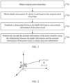
- FIG. 1 is a schematic flowchart of a predictive encoding method for azimuth information of a point cloud according to an embodiment of the present invention.
- the predictive encoding method for azimuth information of a point cloud specifically includes the following steps.
- Step 1 Obtain original point cloud data.
- the original point cloud data generally includes a set of three-dimensional spatial points, each spatial point records geometric position information of the spatial point and additional attribute information such as color, reflectivity, and normal.
- Geometric position information of a point cloud is usually expressed based on a Cartesian coordinate system; in other words, coordinates x , y , and z of a point are used for representation.
- the original point cloud data may be obtained by a laser radar through scanning, or may be obtained by using common data sets provided by various platforms.
- the obtained geometric position information of the original point cloud data is represented based on the Cartesian coordinate system. It should be noted that a method of representing the geometric position information of the original point cloud data is not limited to Cartesian coordinates.
- Step 2 Obtain depth information of a point cloud based on the original point cloud data.
- r represents depth information of each point in the original point cloud data
- x and y are Cartesian coordinate components of each point.
- Step 3 Establish a relationship between the depth information and azimuth information of the point cloud.
- a relationship between the depth information and the azimuth information of the point cloud may be established by using a mathematical derivation method.
- the relationship between the depth information and the azimuth information of the point cloud may be established from an algebraic perspective based on a collection principle of a laser radar.
- the laser radar is formed by combining and arranging a plurality of lasers (laser scanners) distributed along both sides of a central axis.
- Each laser has a fixed pitch angle, and may be regarded as a relatively independent collection system.
- the lasers rotate by 360 degrees around the central axis of the laser radar, perform sampling at fixed rotation angle intervals during rotation, and return originally collected information of a sampling point, that is, originally collected distance information r 0 of the sampling point, an index number i ( ⁇ 0 ) of a laser to which the sampling point belongs, and originally collected azimuth information ⁇ 0 .
- the information is expressed based on a local cylindrical coordinate system in which a corresponding laser is an origin.
- FIG. 2 is a schematic diagram of calibration of a laser radar according to an embodiment of the present invention.
- a calibration formula of the laser radar is as follows.
- D corr is a distance correction factor of the laser to which the point belongs, that is, an i th laser of the laser radar, V o is a vertical offset of the laser to which the point belongs, H o is a horizontal offset of the laser to which the point belongs, ⁇ 0 is a vertical elevation angle of the laser to which the point belongs, and ⁇ is a horizontal correction angle of the laser to which the point belongs. All the foregoing parameters are calibration parameters of the laser.
- azimuth information ⁇ of the point is calculated as follows by using x and y .
- ⁇ 0 is the originally collected azimuth information of the point
- H o is the horizontal offset of the laser to which the point belongs
- ⁇ is the horizontal correction angle of the laser to which the point belongs
- both H o and ⁇ are calibration parameters of the laser.
- the relationship between the depth information and the azimuth information of the point cloud may alternatively be established from a geometric perspective based on a collection principle of the laser radar.
- the laser radar performs calibration in a process of collecting the point cloud, and converts originally collected information represented in a laser local cylindrical coordinate system into a Cartesian coordinate system in which the bottom of the laser radar is used as a unified origin, to form a point cloud of the laser radar in the unified Cartesian coordinate system, that is, a point cloud finally collected by a device, as shown in FIG. 2 .
- the azimuth information of the point cloud is represented on an x-y plane in the Cartesian coordinate system, and therefore, FIG. 3 is further derived from FIG. 2 .
- FIG. 3 is a schematic diagram of calibration of the laser radar on the x-y plane according to an embodiment of the present invention.
- ⁇ 0 is the originally collected azimuth information of the point
- H o is the horizontal offset of the laser to which the point belongs
- ⁇ is the horizontal correction angle of the laser to which the point belongs
- both H o and ⁇ are calibration parameters of the laser.
- FIG. 4 is a schematic diagram of a relation curve between depth information and an azimuth residual of a laser collection point according to an embodiment of the present invention.
- an x coordinate is depth information r of a point
- the relationship between the depth information and the azimuth information of the point cloud may alternatively be established by using a fitting method.
- ⁇ and H o in the relational expression may be calculated based on information about the selected points.
- a parameter estimation process is described in detail below by using an example in which two points are selected from the points collected by the same laser to estimate parameters.
- FIG. 5 is a schematic diagram of segmented hopping of a relation curve between depth information of a laser collection point and an azimuth residual according to an embodiment of the present invention.
- points collected by all lasers are sequentially sorted based on the depth information r and the azimuth residual ⁇ ⁇ . Because the relation curve between the depth information r and the azimuth residual ⁇ ⁇ in this embodiment hops in segments, the two selected points need to be located on a same segment of segmented curve, and a segmented curve including most points needs to be selected. Finally, points on both ends of the segment curve that meet a condition are used as two finally selected points.
- H o may have two possible solutions, and a value that has a minimum absolute value and that meets a condition needs to be selected from the two possible solutions as H o obtained through final solution and estimation.
- ⁇ has only one possible solution, and may be obtained by solving an inverse trigonometric function of tan ⁇ obtained through calculation of the foregoing formula.
- estimated parameters H o and ⁇ of each laser need to be encoded.
- Specific encoding may be completed by using an existing entropy encoding technology. If the parameters H o and ⁇ are known, the parameters H o and ⁇ do not need to be estimated and encoded.
- Step 4 Predictively encode the azimuth information of the point cloud by using the relationship between the depth information and the azimuth information of the point cloud, to obtain coded stream information.
- cylindrical coordinates ( r , ⁇ , i ) of each point in the point cloud are calculated based on Cartesian coordinates ( x , y , z ) of the point.
- r represents depth information of the point
- ⁇ represents azimuth information of the point
- i represents an ID of a laser to which the point belongs
- V o k is a vertical offset of a k th laser
- ⁇ 0 k is a vertical elevation angle of the k th laser
- both V o k and ⁇ 0 k are calibration parameters of the k th laser.
- an azimuth index j of the current point an approximate value ⁇ 0 ' of an originally collected azimuth, and an azimuth residual ⁇ ⁇ are calculated based on resolution ⁇ speed of a sampling angle of the laser radar.
- an initial predicted value ⁇ ⁇ of the azimuth residual ⁇ ⁇ is obtained based on the depth information r of the current point and a corresponding relational expression between the depth information and the azimuth information.
- H o i represents a horizontal offset of an i th laser to which the current point belongs, ⁇ i represents a horizontal correction angle of the i th laser to which the current point belongs, and both H o i and ⁇ i are calibration parameters of the i th laser.
- azimuth residuals calculated in different manners may have different characteristics, and whether to correspondingly shift the initial predicted value of the azimuth residual needs to be determined based on the characteristic of the azimuth residual.
- the azimuth residual ⁇ ⁇ ⁇ ⁇ speed 2 , ⁇ speed 2 calculated in this embodiment does not continuously change as the depth information r increases, but is continuous in segments. Therefore, as shown in FIG. 5 , the initial predicted value ⁇ ⁇ obtained by using the relational expression needs to be correspondingly shifted, to obtain a final predicted value ⁇ of the azimuth residual and a prediction residual res ⁇ ⁇ of the azimuth residual, where ⁇ ⁇ ⁇ ⁇ speed 2 , ⁇ speed 2 .
- the prediction residual res ⁇ ⁇ of the azimuth residual may be encoded by using an existing entropy encoding technology.
- the azimuth auxiliary information needs to be correspondingly encoded.
- the azimuth auxiliary information is an azimuth index j of a point.
- the azimuth index j of the point may be encoded in a differential encoding manner.
- the relationship between the depth information and the azimuth information of the point cloud is established, and cross-component prediction is performed on the azimuth information by using the depth information of the point cloud and the foregoing relationship.
- the method provided in the present invention can further improve prediction precision of the azimuth information of the point cloud, and reduce a prediction residual of the azimuth information, so that distribution of prediction residuals of an azimuth is more centralized. In this way, a more effective context model is established in an entropy encoding process, and therefore, encoding efficiency of the point cloud is improved.
- FIG. 6 is a schematic diagram of a structure of a predictive encoding apparatus for azimuth information of a point cloud according to an embodiment of the present invention.
- the apparatus includes:
- the apparatus provided in this embodiment can implement the encoding method provided in Embodiment 1, and a detailed process is not described herein again.
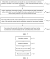
- FIG. 7 is a schematic flowchart of a predictive decoding method for azimuth information of a point cloud according to an embodiment of the present invention. The method specifically includes the following steps: Step 1: Obtain coded stream information and decode the coded stream information to obtain a prediction residual of an azimuth residual of a point cloud and azimuth auxiliary information.
- a decoder obtains compressed coded stream information, and decodes the coded stream information by using an existing entropy decoding technology to obtain the prediction residual of the azimuth residual of the point cloud and the azimuth auxiliary information.
- Step 2 Predict an azimuth of the point cloud by using reconstructed depth information and a relationship between the depth information and azimuth information, to obtain a final predicted value of the azimuth residual.
- the azimuth residual information of the point is predicted by using depth information of the point cloud reconstructed by the decoder and the relationship between the depth information and the azimuth information, to obtain an initial predicted value of the azimuth residual, and then, the initial predicted value of the azimuth residual is selectively shifted to obtain a final predicted value of the azimuth residual.
- Step 3 Reconstruct the azimuth residual of the point cloud based on the final predicted value of the azimuth residual and the prediction residual of the azimuth residual.
- the final predicted value of the azimuth residual and the prediction residual of the azimuth residual obtained through decoding are added, so that the azimuth residual of the point cloud can be reconstructed.
- Step 4 Reconstruct the azimuth information of the point cloud based on the reconstructed azimuth residual and the azimuth auxiliary information.
- an approximate value of an originally collected azimuth of the point cloud is calculated by using a decoded azimuth index, and then the reconstructed azimuth residual and the approximate value of the originally collected azimuth are added, so that the azimuth information of the point cloud can be reconstructed.
- FIG. 8 is a schematic diagram of a structure of a predictive decoding apparatus for azimuth information of a point cloud according to an embodiment of the present invention.
- the apparatus includes:
- the apparatus provided in this embodiment can implement the decoding method provided in Embodiment 3, and a detailed process is not described herein again.
Landscapes
- Engineering & Computer Science (AREA)
- Multimedia (AREA)
- Physics & Mathematics (AREA)
- Signal Processing (AREA)
- General Physics & Mathematics (AREA)
- Theoretical Computer Science (AREA)
- Optics & Photonics (AREA)
- Computer Vision & Pattern Recognition (AREA)
- Algebra (AREA)
- Pure & Applied Mathematics (AREA)
- Mathematical Optimization (AREA)
- Mathematical Analysis (AREA)
- Image Processing (AREA)
- Length Measuring Devices By Optical Means (AREA)
- Optical Radar Systems And Details Thereof (AREA)
Abstract
Description
- This application claims priority to
Chinese Patent Application No. 202110580220.6, filed with the China National Intellectual Property Administration on May 26, 2021 - The present invention pertains to the field of a point cloud encoding/decoding technologies, and particularly relates to a predictive encoding/decoding method and apparatus for azimuth information of a point cloud.
- With the improvement of a hardware processing capability and the rapid development of computer vision, three-dimensional point cloud data has been widely used in fields such as virtual reality, augmented reality, self-driving, and environment modeling. However, a large-scale point cloud usually has a large amount of data, which is not conducive to the transmission and storage of the point cloud data. Therefore, the large-scale point cloud needs to be efficiently encoded/decoded.
- In a conventional encoding/decoding technology for the large-scale point cloud, Cartesian coordinates of the point cloud are usually predicted by using cylindrical coordinates (including azimuth information, depth information, and the like) of the point cloud. Therefore, each cylindrical coordinate component of the point cloud needs to be predictively encoded in the prior art. Specifically, for predictive encoding of the azimuth information of the point cloud, a point cloud encoding/decoding method based on a prediction tree is provided in the
prior art 1. First, a multiple of a difference between an azimuth of a current point and an azimuth obtained in a selected prediction mode with respect to an angular velocity of rotation needs to be calculated, and then the azimuth of the current point is predicted by using an integral multiple of the angular velocity of rotation and the azimuth obtained in the selected prediction mode, to obtain a prediction residual, and finally the integral multiple and the prediction residual of the azimuth are encoded to reconstruct azimuth information in the same manner on a decoder. A point cloud encoding/decoding method based on a single-chain structure is provided in theprior art 2. First, an azimuth of each point is quantized, and a quantized value of the azimuth of each point may be restored by using the single-chain structure. Then, a quantized residual of the azimuth is predictively encoded, and specifically, a prediction mode list is created, and an optimal prediction mode is selected by an encoder, to complete predictive encoding of azimuth information of a point cloud. - However, when the two methods are used to predictively encode the azimuth information of the point cloud, only encoded azimuth information is used for prediction, and a relationship between other information and the azimuth information is not considered. Consequently, the obtained prediction residuals of the azimuth information are large and are not centralized, and the validity of an entropy encoding context model is destroyed, and therefore, encoding efficiency of the azimuth information of the point cloud is low.
- To resolve the foregoing problem in the prior art, the present invention provides a predictive encoding/decoding method and apparatus for azimuth information of a point cloud. Technical problems in the present invention are resolved by the following technical solutions:
- A predictive encoding method for azimuth information of a point cloud includes:
- obtaining original point cloud data;
- obtaining depth information of a point cloud based on the original point cloud data;
- establishing a relationship between the depth information and azimuth information of the point cloud; and
- predictively encoding the azimuth information of the point cloud by using the relationship between the depth information and the azimuth information of the point cloud, to obtain coded stream information.
- In an embodiment of the present invention, the establishing a relationship between the depth information and azimuth information of the point cloud includes:
- establishing the relationship between the depth information and the azimuth information of the point cloud by using a mathematical derivation method; or
- establishing the relationship between the depth information and the azimuth information of the point cloud by using a fitting method.
- In an embodiment of the present invention, a relational expression between the depth information and the azimuth information of the point cloud is established by using the mathematical derivation method as follows:

- ϕ represents azimuth information of a point, ϕ 0 represents originally collected azimuth information of the point, r represents depth information of the point, α represents a horizontal correction angle of a laser to which the point belongs, and Ho represents a horizontal offset of the laser to which the point belongs.
- In an embodiment of the present invention, a relational expression between the depth information and the azimuth information of the point cloud is established by using the mathematical derivation method as follows:

- ϕ represents azimuth information of a point, ϕ 0 represents originally collected azimuth information of the point, r represents depth information of the point, α represents a horizontal correction angle of a laser to which the point belongs, and Ho represents a horizontal offset of the laser to which the point belongs.
- In an embodiment of the present invention, after the relational expression between the depth information and the azimuth information of the point cloud is obtained, the method further includes:
selecting several points from points collected by a same laser or encoded points and estimating unknown parameters α and Ho in the relational expression based on information about the selected points. - In an embodiment of the present invention, formulas for estimating the unknown parameters α and Ho by selecting two points are:


- r 1 and r 2 separately represent depth information of the two selected points, and Δϕ 1 and Δϕ 2 separately represent azimuth residuals of the two selected points.
- In an embodiment of the present invention, the predictively encoding the azimuth information of the point cloud by using the relationship between the depth information and the azimuth information of the point cloud includes:
- predicting the azimuth of the point cloud based on the relationship between the depth information and the azimuth information of the point cloud, to obtain an initial predicted value of an azimuth residual;
- selectively shifting the initial predicted value of the azimuth residual to obtain a final predicted value of the azimuth residual and a prediction residual of the azimuth residual; and
- encoding the prediction residual of the azimuth residual and azimuth auxiliary information.
- Another embodiment of the present invention provides a predictive encoding apparatus for azimuth information of a point cloud, including:
- a data obtaining module, configured to obtain original point cloud data;
- a data processing module, configured to obtain depth information of a point cloud based on the original point cloud data;
- a first calculation module, configured to establish a relationship between the depth information and azimuth information of the point cloud; and
- a predictive encoding module, configured to predictively encode the azimuth information of the point cloud by using the relationship between the depth information and the azimuth information of the point cloud, to obtain coded stream information.
- Still another embodiment of the present invention further provides a prediction decoding method for azimuth information of a point cloud, including:
- obtaining coded stream information and decoding the coded stream information to obtain a prediction residual of an azimuth residual of a point cloud and azimuth auxiliary information;
- predicting an azimuth of the point cloud by using reconstructed depth information and a relationship between the depth information and azimuth information, to obtain a final predicted value of the azimuth residual;
- reconstructing the azimuth residual of the point cloud based on the final predicted value of the azimuth residual and the prediction residual of the azimuth residual; and
- reconstructing the azimuth information of the point cloud based on the reconstructed azimuth residual and the azimuth auxiliary information.
- Yet another embodiment of the present invention further provides a prediction decoding apparatus for azimuth information of a point cloud, including:
- a decoding module, configured to obtain coded stream information and decode the coded stream information to obtain a prediction residual of an azimuth residual of a point cloud and azimuth auxiliary information;
- a prediction module, configured to predict an azimuth of the point cloud by using reconstructed depth information and a relationship between the depth information and azimuth information, to obtain a final predicted value of the azimuth residual;
- a second calculation module, configured to reconstruct the azimuth residual of the point cloud based on the final predicted value of the azimuth residual and the prediction residual of the azimuth residual; and
- a reconstruction module, configured to reconstruct the azimuth information of the point cloud based on the reconstructed azimuth residual and the azimuth auxiliary information.
- Beneficial effects of the present invention are as follows:
In the present invention, a relationship between depth information and azimuth information of a point cloud is established, and cross-component prediction is performed on the azimuth information by using the depth information of the point cloud and the foregoing relationship. In this way, prediction precision of the azimuth information of the point cloud is further improved, and a prediction residual of the azimuth information can be reduced, so that distribution of prediction residuals of an azimuth is more centralized. In this way, a more effective context model is established in an entropy encoding process, and therefore, encoding efficiency of the point cloud is improved. - The present invention is further described in detail below with reference to the accompanying drawings and embodiments.
-
-
FIG. 1 is a schematic flowchart of a predictive encoding method for azimuth information of a point cloud according to an embodiment of the present invention; -
FIG. 2 is a schematic diagram of calibration of a laser radar according to an embodiment of the present invention; -
FIG. 3 is a schematic diagram of calibration of a laser radar on an x-y plane according to an embodiment of the present invention; -
FIG. 4 is a schematic diagram of a relation curve of depth information of a specific laser collection point and an azimuth residual according to an embodiment of the present invention; -
FIG. 5 is a schematic diagram of segmented hopping of a relation curve of depth information of a specific laser collection point and an azimuth residual according to an embodiment of the present invention; -
FIG. 6 is a schematic diagram of a structure of a predictive encoding apparatus for azimuth information of a point cloud according to an embodiment of the present invention; -
FIG. 7 is a schematic flowchart of a predictive decoding method for azimuth information of a point cloud according to an embodiment of the present invention; and -
FIG. 8 is a schematic diagram of a structure of a predictive decoding apparatus for azimuth information of a point cloud according to an embodiment of the present invention. - The present invention is further described in detail below with reference to specific embodiments, but implementations of the present invention are not limited thereto.
-
FIG. 1 is a schematic flowchart of a predictive encoding method for azimuth information of a point cloud according to an embodiment of the present invention. The predictive encoding method for azimuth information of a point cloud specifically includes the following steps. - Specifically, the original point cloud data generally includes a set of three-dimensional spatial points, each spatial point records geometric position information of the spatial point and additional attribute information such as color, reflectivity, and normal. Geometric position information of a point cloud is usually expressed based on a Cartesian coordinate system; in other words, coordinates x, y, and z of a point are used for representation. The original point cloud data may be obtained by a laser radar through scanning, or may be obtained by using common data sets provided by various platforms.
- In this embodiment, the obtained geometric position information of the original point cloud data is represented based on the Cartesian coordinate system. It should be noted that a method of representing the geometric position information of the original point cloud data is not limited to Cartesian coordinates.
- Specifically, in this embodiment, the depth information of the point cloud may be calculated by using the following formula:

- r represents depth information of each point in the original point cloud data, and x and y are Cartesian coordinate components of each point.
- In addition, it should be noted that the depth information of the point cloud may alternatively be calculated by using a formula

- In this embodiment, a relationship between the depth information and the azimuth information of the point cloud may be established by using a mathematical derivation method.
- For example, the relationship between the depth information and the azimuth information of the point cloud may be established from an algebraic perspective based on a collection principle of a laser radar.
- Specifically, the laser radar is formed by combining and arranging a plurality of lasers (laser scanners) distributed along both sides of a central axis. Each laser has a fixed pitch angle, and may be regarded as a relatively independent collection system. The lasers rotate by 360 degrees around the central axis of the laser radar, perform sampling at fixed rotation angle intervals during rotation, and return originally collected information of a sampling point, that is, originally collected distance information r 0 of the sampling point, an index number i(θ 0 ) of a laser to which the sampling point belongs, and originally collected azimuth information ϕ 0. The information is expressed based on a local cylindrical coordinate system in which a corresponding laser is an origin. However, to facilitate subsequent processing of the point cloud, originally collected data of the point cloud needs to be converted to a Cartesian coordinate system in which the bottom of the laser radar is used as a unified origin to form a point cloud of the laser radar in the unified Cartesian coordinate system, that is, a point cloud finally collected by a device. This conversion process is a calibration process of the laser radar. As shown in
FIG. 2, FIG. 2 is a schematic diagram of calibration of a laser radar according to an embodiment of the present invention. A calibration formula of the laser radar is as follows. Originally collected information (r 0,i(θ 0),ϕ 0) of a point is converted into Cartesian coordinates (x,y,z), r 0 in the originally collected information is originally collected distance information of the point, i(θ 0) is an index number of a laser to which the point belongs, and ϕ 0 is originally collected azimuth information of the point.


- Dcorr is a distance correction factor of the laser to which the point belongs, that is, an i th laser of the laser radar, Vo is a vertical offset of the laser to which the point belongs, Ho is a horizontal offset of the laser to which the point belongs, θ 0 is a vertical elevation angle of the laser to which the point belongs, and α is a horizontal correction angle of the laser to which the point belongs. All the foregoing parameters are calibration parameters of the laser.
- Then, (r 0 + Dcorr )·cosθ 0 ≈ r projected to an x-y plane is set, where r is depth information of a current point (x,y,z). In this case,


- Then, conversion is performed by using an auxiliary angle formula to obtain:


- In this case, azimuth information ϕ of the point is calculated as follows by using x and y.


- ϕ 0 is the originally collected azimuth information of the point, Ho is the horizontal offset of the laser to which the point belongs, α is the horizontal correction angle of the laser to which the point belongs, and both Ho and α are calibration parameters of the laser.
- In another embodiment of the present invention, the relationship between the depth information and the azimuth information of the point cloud may alternatively be established from a geometric perspective based on a collection principle of the laser radar.
- Specifically, the laser radar performs calibration in a process of collecting the point cloud, and converts originally collected information represented in a laser local cylindrical coordinate system into a Cartesian coordinate system in which the bottom of the laser radar is used as a unified origin, to form a point cloud of the laser radar in the unified Cartesian coordinate system, that is, a point cloud finally collected by a device, as shown in
FIG. 2 . However, the azimuth information of the point cloud is represented on an x-y plane in the Cartesian coordinate system, and therefore,FIG. 3 is further derived fromFIG. 2 .FIG. 3 is a schematic diagram of calibration of the laser radar on the x-y plane according to an embodiment of the present invention. - It may be derived from
FIG. 3 that

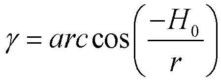

- ϕ 0 is the originally collected azimuth information of the point, Ho is the horizontal offset of the laser to which the point belongs, α is the horizontal correction angle of the laser to which the point belongs, and both Ho and α are calibration parameters of the laser.
- It should be noted that, because approximate treatment is adopted during derivation from the algebraic perspective, the relational expressions obtained in the foregoing two manners are different in form, but are almost identical in relation curves. As shown in
FIG. 4, FIG. 4 is a schematic diagram of a relation curve between depth information and an azimuth residual of a laser collection point according to an embodiment of the present invention. In the figure, an x coordinate is depth information r of a point, and a y coordinate is an azimuth residual Δϕ of the point, where Δϕ = ϕ - ϕ 0, ϕ is azimuth information of the point, and ϕ 0 is originally collected azimuth information of the point. - In addition, the relationship between the depth information and the azimuth information of the point cloud may alternatively be established by using a fitting method.
- After the relational expression between the depth information and the azimuth information of the point cloud is obtained, unknown parameters in the relational expression further need to be estimated, so that the azimuth information of the point cloud is subsequently predicted by using the relationship between the depth information and the azimuth information.
- Specifically, several points may be selected from points collected by a same laser or encoded points, and unknown parameters α and Ho in the relational expression may be calculated based on information about the selected points.
- A parameter estimation process is described in detail below by using an example in which two points are selected from the points collected by the same laser to estimate parameters.
- First, two points are selected from the points collected by the same laser. Specific descriptions are as follows:
Depth information r and azimuth information ϕ of the points collected by the same laser are calculated based on the following formula:

- Then, an approximate value ϕ 0 ' of the originally collected azimuth of the point is calculated based on the following formula, to obtain the azimuth residual Δϕ:


- j is an azimuth index of the point, and ϕspeed is resolution of a sampling angle of the laser. In this case, the azimuth residual

FIG. 5, FIG. 5 is a schematic diagram of segmented hopping of a relation curve between depth information of a laser collection point and an azimuth residual according to an embodiment of the present invention. - Then, points collected by all lasers are sequentially sorted based on the depth information r and the azimuth residual Δϕ. Because the relation curve between the depth information r and the azimuth residual Δϕ in this embodiment hops in segments, the two selected points need to be located on a same segment of segmented curve, and a segmented curve including most points needs to be selected. Finally, points on both ends of the segment curve that meet a condition are used as two finally selected points.
- Then, unknown parameters α and Ho in the relational expression are estimated based on the two selected points. Specific descriptions are as follows:
The relational expression between the depth information r and the azimuth residual Δϕ is obtained based on the relational expression between the depth information r and the azimuth information ϕ of the point cloud:
- The relational expression between the depth information r of the point cloud and the azimuth residual Δϕ is further as follows:

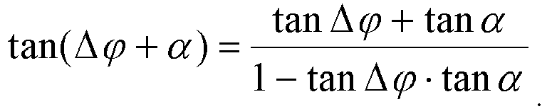
- r and Δϕ are substituted into the relational expression between r and Δϕ, to obtain:

- The depth information and the azimuth residual of the two selected points are respectively denoted as (r 1,Δϕ 1) and (r 2,Δϕ 2), and (r 1,Δϕ 1) and (r 2,Δϕ 2) are substituted to obtain an equation set:


- Unknown numbers in the equation set are Ho and tan α, and finally, the binary equation set is solved to obtain:


- It should be noted that Ho may have two possible solutions, and a value that has a minimum absolute value and that meets a condition needs to be selected from the two possible solutions as Ho obtained through final solution and estimation. α has only one possible solution, and may be obtained by solving an inverse trigonometric function of tan α obtained through calculation of the foregoing formula.
- Further, to predict the azimuth information of the point cloud by using the relationship on a decoder, estimated parameters Ho and α of each laser need to be encoded. Specific encoding may be completed by using an existing entropy encoding technology. If the parameters Ho and α are known, the parameters Ho and α do not need to be estimated and encoded.
- After the parameters Ho and α in the relational expression are obtained, the relationship between the depth information and the azimuth information of the point cloud is entirely established.
- Step 4: Predictively encode the azimuth information of the point cloud by using the relationship between the depth information and the azimuth information of the point cloud, to obtain coded stream information. This specifically includes the following steps:
41) Predict the azimuth of the point cloud based on the relationship between the depth information and the azimuth information of the point cloud, to obtain an initial predicted value of an azimuth residual. - Specifically, first, cylindrical coordinates (r,ϕ,i) of each point in the point cloud are calculated based on Cartesian coordinates (x,y,z) of the point. Calculation formulas of the cylindrical coordinates are as follows:


- r represents depth information of the point, ϕ represents azimuth information of the point, i represents an ID of a laser to which the point belongs,


- Then, an azimuth index j of the current point, an approximate value ϕ 0 ' of an originally collected azimuth, and an azimuth residual Δϕ are calculated based on resolution ϕspeed of a sampling angle of the laser radar. Specific calculation formulas are as follows:


- Finally, an initial predicted value Δϕ̂ of the azimuth residual Δϕ is obtained based on the depth information r of the current point and a corresponding relational expression between the depth information and the azimuth information. A specific formula is as follows:
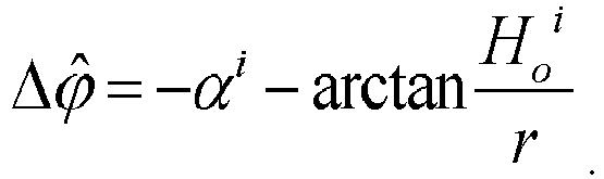


- 42) Selectively shift the initial predicted value of the azimuth residual to obtain a final predicted value of the azimuth residual and a prediction residual of the azimuth residual.
- It should be noted that azimuth residuals calculated in different manners may have different characteristics, and whether to correspondingly shift the initial predicted value of the azimuth residual needs to be determined based on the characteristic of the azimuth residual.
- The azimuth residual

FIG. 5 , the initial predicted value Δϕ̂ obtained by using the relational expression needs to be correspondingly shifted, to obtain a final predicted value Δφ̃ of the azimuth residual and a prediction residual res Δϕ of the azimuth residual, where Δφ̃ ∈
- Specifically, a shifting method may be as follows: First, a reminder obtained after the initial predicted value Δϕ̂ of the azimuth residual is divided by the resolution ϕspeed of the sampling angle of the laser radar is used to initialize the final predicted value Δφ̃ of the azimuth residual, that is, Δφ̃ = Δφ̂ % φspeed. Then, determining is performed; if Δφ̃ is greater than


- In addition, another shifting method may alternatively be selected. This is not specifically limited in this embodiment.
- 43) Encode the prediction residual of the azimuth residual and azimuth auxiliary information.
- Specifically, the prediction residual res Δϕ of the azimuth residual may be encoded by using an existing entropy encoding technology. In addition, the azimuth auxiliary information needs to be correspondingly encoded. In this embodiment, the azimuth auxiliary information is an azimuth index j of a point. Specifically, the azimuth index j of the point may be encoded in a differential encoding manner.
- In the present invention, the relationship between the depth information and the azimuth information of the point cloud is established, and cross-component prediction is performed on the azimuth information by using the depth information of the point cloud and the foregoing relationship. Compared with an existing method for performing prediction by using only encoded information of an azimuth, the method provided in the present invention can further improve prediction precision of the azimuth information of the point cloud, and reduce a prediction residual of the azimuth information, so that distribution of prediction residuals of an azimuth is more centralized. In this way, a more effective context model is established in an entropy encoding process, and therefore, encoding efficiency of the point cloud is improved.
- Based on
Embodiment 1, this embodiment provides a predictive encoding apparatus for azimuth information of a point cloud. Refer toFIG. 6. FIG. 6 is a schematic diagram of a structure of a predictive encoding apparatus for azimuth information of a point cloud according to an embodiment of the present invention. The apparatus includes: - a
data obtaining module 11, configured to obtain original point cloud data; - a
data processing module 12, configured to obtain depth information of a point cloud based on the original point cloud data; - a
first calculation module 13, configured to establish a relationship between the depth information and azimuth information of the point cloud; and - a
predictive encoding module 14, configured to predictively encode the azimuth information of the point cloud by using the relationship between the depth information and the azimuth information of the point cloud, to obtain coded stream information. - The apparatus provided in this embodiment can implement the encoding method provided in
Embodiment 1, and a detailed process is not described herein again. - This embodiment provides a predictive decoding method for azimuth information of a point cloud. Refer to
FIG. 7. FIG. 7 is a schematic flowchart of a predictive decoding method for azimuth information of a point cloud according to an embodiment of the present invention. The method specifically includes the following steps:
Step 1: Obtain coded stream information and decode the coded stream information to obtain a prediction residual of an azimuth residual of a point cloud and azimuth auxiliary information. - A decoder obtains compressed coded stream information, and decodes the coded stream information by using an existing entropy decoding technology to obtain the prediction residual of the azimuth residual of the point cloud and the azimuth auxiliary information.
- Step 2: Predict an azimuth of the point cloud by using reconstructed depth information and a relationship between the depth information and azimuth information, to obtain a final predicted value of the azimuth residual.
- Specifically, similar to a procedure on an encoder, first, the azimuth residual information of the point is predicted by using depth information of the point cloud reconstructed by the decoder and the relationship between the depth information and the azimuth information, to obtain an initial predicted value of the azimuth residual, and then, the initial predicted value of the azimuth residual is selectively shifted to obtain a final predicted value of the azimuth residual.
- Step 3: Reconstruct the azimuth residual of the point cloud based on the final predicted value of the azimuth residual and the prediction residual of the azimuth residual.
- Specifically, the final predicted value of the azimuth residual and the prediction residual of the azimuth residual obtained through decoding are added, so that the azimuth residual of the point cloud can be reconstructed.
- Step 4: Reconstruct the azimuth information of the point cloud based on the reconstructed azimuth residual and the azimuth auxiliary information.
- Specifically, first, an approximate value of an originally collected azimuth of the point cloud is calculated by using a decoded azimuth index, and then the reconstructed azimuth residual and the approximate value of the originally collected azimuth are added, so that the azimuth information of the point cloud can be reconstructed.
- Based on
Embodiment 3, this embodiment provides a predictive decoding apparatus for azimuth information of a point cloud. Refer toFIG. 8. FIG. 8 is a schematic diagram of a structure of a predictive decoding apparatus for azimuth information of a point cloud according to an embodiment of the present invention. The apparatus includes: - a
decoding module 21, configured to obtain coded stream information and decode the coded stream information to obtain a prediction residual of an azimuth residual of a point cloud and azimuth auxiliary information; - a
prediction module 22, configured to predict an azimuth of the point cloud by using reconstructed depth information and a relationship between the depth information and azimuth information, to obtain a final predicted value of the azimuth residual; - a
second calculation module 23, configured to reconstruct the azimuth residual of the point cloud based on the predicted value of the azimuth residual and the prediction residual of the azimuth residual; and - a
reconstruction module 24, configured to reconstruct the azimuth information of the point cloud based on the reconstructed azimuth residual and the azimuth auxiliary information. - The apparatus provided in this embodiment can implement the decoding method provided in
Embodiment 3, and a detailed process is not described herein again. - The foregoing content is further detailed descriptions of the present invention with reference to specific preferred implementations, and it cannot be assumed that specific implementation of the present invention is limited to these descriptions. For a person of ordinary skill in the art to which the present invention belongs, several simple deductions or substitutions may be made without departing from the inventive concept, which shall be regarded as falling within the protection scope of the present invention.
Claims (10)
- A predictive encoding method for azimuth information of a point cloud, comprising:obtaining original point cloud data;obtaining depth information of a point cloud based on the original point cloud data;establishing a relationship between the depth information and azimuth information of the point cloud; andpredictively encoding the azimuth information of the point cloud by using the relationship between the depth information and the azimuth information of the point cloud, to obtain coded stream information.
- The predictive encoding method for azimuth information of the point cloud according to claim 1, wherein the establishing the relationship between the depth information and azimuth information of the point cloud comprises:establishing the relationship between the depth information and the azimuth information of the point cloud by using a mathematical derivation method; orestablishing the relationship between the depth information and the azimuth information of the point cloud by using a fitting method.
- The predictive encoding method for azimuth information of the point cloud according to claim 2, wherein the relational expression between the depth information and the azimuth information of the point cloud is established by using the mathematical derivation method as follows:

ϕ represents azimuth information of a point, ϕ 0 represents originally collected azimuth information of the point, r represents depth information of the point, α represents a horizontal correction angle of a laser to which the point belongs, and Ho represents a horizontal offset of the laser to which the point belongs. - The predictive encoding method for azimuth information of the point cloud according to claim 2, wherein the relational expression between the depth information and the azimuth information of the point cloud is established by using the mathematical derivation method as follows:

ϕ represents azimuth information of a point, ϕ 0 represents originally collected azimuth information of the point, r represents depth information of the point, α represents a horizontal correction angle of a laser to which the point belongs, and Ho represents a horizontal offset of the laser to which the point belongs. - The predictive encoding method for azimuth information of the point cloud according to claim 3 or 4, wherein after the relational expression between the depth information and the azimuth information of the point cloud is obtained, the method further comprises:
selecting several points from points collected by a same laser or encoded points and estimating unknown parameters α and Ho in the relational expression based on information about the selected points. - The predictive encoding method for azimuth information of the point cloud according to claim 5, wherein a formula for estimating the unknown parameters α and Ho by selecting two points is:


r 1 and r 2 separately represent depth information of the two selected points, and Δϕ 1 and Δϕ 2 separately represent azimuth residuals of the two selected points. - The predictive encoding method for azimuth information of the point cloud according to claim 1, wherein the predictively encoding the azimuth information of the point cloud by using the relationship between the depth information and the azimuth information of the point cloud comprises:predicting the azimuth of the point cloud based on the relationship between the depth information and the azimuth information of the point cloud, to obtain an initial predicted value of an azimuth residual;selectively shifting the initial predicted value of the azimuth residual to obtain a final predicted value of the azimuth residual and a prediction residual of the azimuth residual; andencoding the prediction residual of the azimuth residual and azimuth auxiliary information.
- A predictive encoding apparatus for azimuth information of a point cloud, comprising:a data obtaining module (11), configured to obtain original point cloud data;a data processing module (12), configured to obtain depth information of a point cloud based on the original point cloud data;a first calculation module (13), configured to establish a relationship between the depth information and azimuth information of the point cloud; anda predictive encoding module (14), configured to predictively encode the azimuth information of the point cloud by using the relationship between the depth information and the azimuth information of the point cloud, to obtain coded stream information.
- A predictive decoding method for azimuth information of a point cloud, comprising:obtaining coded stream information and decoding the coded stream information to obtain a prediction residual of an azimuth residual of a point cloud and azimuth auxiliary information;predicting an azimuth of the point cloud by using reconstructed depth information and a relationship between the depth information and azimuth information, to obtain a final predicted value of the azimuth residual;reconstructing the azimuth residual of the point cloud based on the final predicted value of the azimuth residual and the prediction residual of the azimuth residual; andreconstructing the azimuth information of the point cloud based on the reconstructed azimuth residual and the azimuth auxiliary information.
- A predictive decoding apparatus for azimuth information of a point cloud, comprising:a decoding module (21), configured to obtain coded stream information and decode the coded stream information to obtain a prediction residual of an azimuth residual of a point cloud and azimuth auxiliary information;a prediction module (22), configured to predict an azimuth of the point cloud by using reconstructed depth information and a relationship between the depth information and azimuth information, to obtain a final predicted value of the azimuth residual;a second calculation module (23), configured to reconstruct the azimuth residual of the point cloud based on the final predicted value of the azimuth residual and the prediction residual of the azimuth residual; anda reconstruction module (24), configured to reconstruct the azimuth information of the point cloud based on the reconstructed azimuth residual and the azimuth auxiliary information.
Applications Claiming Priority (2)
| Application Number | Priority Date | Filing Date | Title |
|---|---|---|---|
| CN202110580220.6A CN115412717B (en) | 2021-05-26 | 2021-05-26 | Method and device for predicting coding and decoding of point cloud azimuth information |
| PCT/CN2022/093678 WO2022247716A1 (en) | 2021-05-26 | 2022-05-18 | Prediction encoding and decoding methods and apparatuses for point cloud azimuth information |
Publications (2)
| Publication Number | Publication Date |
|---|---|
| EP4280603A1 true EP4280603A1 (en) | 2023-11-22 |
| EP4280603A4 EP4280603A4 (en) | 2024-08-21 |
Family
ID=84156403
Family Applications (1)
| Application Number | Title | Priority Date | Filing Date |
|---|---|---|---|
| EP22810443.6A Pending EP4280603A4 (en) | 2021-05-26 | 2022-05-18 | METHODS AND APPARATUS FOR PREDICTION ENCODING AND DECODING FOR POINT CLOUD AZIMUTH INFORMATION |
Country Status (4)
| Country | Link |
|---|---|
| US (2) | US12530808B2 (en) |
| EP (1) | EP4280603A4 (en) |
| CN (1) | CN115412717B (en) |
| WO (1) | WO2022247716A1 (en) |
Families Citing this family (6)
| Publication number | Priority date | Publication date | Assignee | Title |
|---|---|---|---|---|
| CN116996674A (en) * | 2022-04-26 | 2023-11-03 | 中兴通讯股份有限公司 | An encoding method, decoding method, communication node and storage medium |
| WO2024149309A1 (en) * | 2023-01-11 | 2024-07-18 | Douyin Vision Co., Ltd. | Method, apparatus, and medium for point cloud coding |
| WO2024212043A1 (en) * | 2023-04-10 | 2024-10-17 | Oppo广东移动通信有限公司 | Encoding method, decoding method, code stream, encoder, decoder, and storage medium |
| CN121100528A (en) * | 2023-07-06 | 2025-12-09 | Oppo广东移动通信有限公司 | Encoding/decoding method, code stream, encoder, decoder, and storage medium |
| CN121058248A (en) * | 2023-07-07 | 2025-12-02 | Oppo广东移动通信有限公司 | Encoding/decoding methods, bitstreams, encoders, decoders, and storage media |
| CN120111256B (en) * | 2025-03-05 | 2025-11-28 | 山东大学 | A Deep Learning-Based Geometric Encoding Method and System for 3D Point Cloud Prediction |
Family Cites Families (13)
| Publication number | Priority date | Publication date | Assignee | Title |
|---|---|---|---|---|
| EP3228985B1 (en) * | 2014-05-05 | 2024-12-18 | Hexagon Technology Center GmbH | Surveying system |
| WO2016185637A1 (en) * | 2015-05-20 | 2016-11-24 | 三菱電機株式会社 | Point-cloud-image generation device and display system |
| US20180053324A1 (en) | 2016-08-19 | 2018-02-22 | Mitsubishi Electric Research Laboratories, Inc. | Method for Predictive Coding of Point Cloud Geometries |
| US10796457B2 (en) * | 2018-06-26 | 2020-10-06 | Intel Corporation | Image-based compression of LIDAR sensor data with point re-ordering |
| BR112021020654A2 (en) | 2019-05-14 | 2022-01-25 | Intel Corp | Device, at least one machine-readable medium, system and method for encoding immersive video |
| WO2020248187A1 (en) * | 2019-06-13 | 2020-12-17 | 深圳市大疆创新科技有限公司 | Point cloud coding method, point cloud decoding method and related device |
| AU2020202698B2 (en) * | 2019-07-18 | 2025-02-27 | Commonwealth Scientific And Industrial Research Organisation | Machine Guidance Integration |
| CN110458939B (en) * | 2019-07-24 | 2022-11-18 | 大连理工大学 | Indoor scene modeling method based on visual angle generation |
| CN110991227B (en) * | 2019-10-23 | 2023-06-30 | 东北大学 | Three-dimensional object identification and positioning method based on depth type residual error network |
| US12307728B2 (en) | 2019-10-31 | 2025-05-20 | Blackberry Limited | Method and system for azimuthal angular prior and tree representation for cloud compression |
| CN111009011B (en) * | 2019-11-28 | 2023-09-19 | 深圳市镭神智能系统有限公司 | Prediction method, device, system and storage medium for vehicle direction angle |
| CN112565734B (en) * | 2020-12-03 | 2022-04-19 | 西安电子科技大学 | Point cloud attribute coding and decoding method and device based on hybrid coding |
| CN112637608B (en) * | 2020-12-18 | 2022-11-29 | 南京邮电大学 | A dynamic point cloud geometric information compression rate distortion optimization method and device |
-
2021
- 2021-05-26 CN CN202110580220.6A patent/CN115412717B/en active Active
-
2022
- 2022-05-18 US US18/270,591 patent/US12530808B2/en active Active
- 2022-05-18 EP EP22810443.6A patent/EP4280603A4/en active Pending
- 2022-05-18 WO PCT/CN2022/093678 patent/WO2022247716A1/en not_active Ceased
-
2025
- 2025-12-29 US US19/435,041 patent/US20260127769A1/en active Pending
Also Published As
| Publication number | Publication date |
|---|---|
| CN115412717B (en) | 2024-05-17 |
| CN115412717A (en) | 2022-11-29 |
| WO2022247716A1 (en) | 2022-12-01 |
| US12530808B2 (en) | 2026-01-20 |
| US20260127769A1 (en) | 2026-05-07 |
| US20240070922A1 (en) | 2024-02-29 |
| EP4280603A4 (en) | 2024-08-21 |
Similar Documents
| Publication | Publication Date | Title |
|---|---|---|
| US12530808B2 (en) | Predictive encoding/decoding method and apparatus for azimuth information of point cloud | |
| EP4184917A1 (en) | Method and device for encoding and decoding point cloud on the basis of two-dimensional regularization planar projection | |
| EP4246442A1 (en) | Point cloud data preprocessing method, point cloud geometry coding method and device, and point cloud geometry decoding method and device | |
| Mongus et al. | Efficient method for lossless LIDAR data compression | |
| WO2022166961A1 (en) | Large-scale point cloud-oriented two-dimensional regular plane projection and encoding and decoding method | |
| CN114022602A (en) | Rendering-based three-dimensional object detector training method | |
| EP4240018A1 (en) | Prediction coding and decoding method and apparatus for point cloud attribute information | |
| EP4236309A1 (en) | Coding and decoding methods for point cloud coordinate transformation residual error, and apparatus | |
| CN114266850A (en) | Point cloud completion method based on continuous standardized stream and anti-refinement network | |
| BRPI0610739A2 (en) | metric inclusion image comparison | |
| Ren et al. | Hybrid encoding fringe and simulation-to-real scene approach for accurate depth estimation in fringe projection profilometry | |
| CN119006557A (en) | Non-visual field target three-dimensional reconstruction method and system based on TOF camera | |
| Liu et al. | Triplane generator-based NeRF-GAN framework for single-view ship reconstruction | |
| US20240013444A1 (en) | Point cloud encoding/decoding method and apparatus based on two-dimensional regularized plane projection | |
| CN118365730B (en) | A method, device, equipment and storage medium for textual graph | |
| EP4246974A1 (en) | Point cloud encoding/decoding method and apparatus based on two-dimensional regularization plane projection | |
| Zou et al. | 3D reconstruction of optical building images based on improved 3D-R2N2 algorithm | |
| Heimann et al. | Jointly Resampling and Reconstructing Corrupted Images for Image Classification using Frequency-Selective Mesh-to-Grid Resampling | |
| CN118711072B (en) | Point cloud-based ground object extraction method, device and equipment | |
| US20250337942A1 (en) | Method, device, and computer program product for compressing point cloud data | |
| Yan et al. | A binary coding method for half-period sinusoidal stripes in focused projection | |
| Yu | Digital Case Image Compression Algorithm based on Deep Learning | |
| Ogaili et al. | Semantic Communication Architectures Using Transformers for 6G Systems | |
| Ye et al. | Semantic Communication-Enhanced Cooperative Object Detection Framework in IoV | |
| CN117610670A (en) | Model training methods, devices, equipment and storage media for quantum state generation |
Legal Events
| Date | Code | Title | Description |
|---|---|---|---|
| STAA | Information on the status of an ep patent application or granted ep patent |
Free format text: STATUS: THE INTERNATIONAL PUBLICATION HAS BEEN MADE |
|
| PUAI | Public reference made under article 153(3) epc to a published international application that has entered the european phase |
Free format text: ORIGINAL CODE: 0009012 |
|
| STAA | Information on the status of an ep patent application or granted ep patent |
Free format text: STATUS: REQUEST FOR EXAMINATION WAS MADE |
|
| 17P | Request for examination filed |
Effective date: 20230609 |
|
| AK | Designated contracting states |
Kind code of ref document: A1 Designated state(s): AL AT BE BG CH CY CZ DE DK EE ES FI FR GB GR HR HU IE IS IT LI LT LU LV MC MK MT NL NO PL PT RO RS SE SI SK SM TR |
|
| REG | Reference to a national code |
Ref country code: DE Ref legal event code: R079 Free format text: PREVIOUS MAIN CLASS: H04N0019103000 Ipc: G06T0009000000 |
|
| A4 | Supplementary search report drawn up and despatched |
Effective date: 20240723 |
|
| RIC1 | Information provided on ipc code assigned before grant |
Ipc: H04N 19/96 20140101ALI20240717BHEP Ipc: H04N 19/103 20140101ALI20240717BHEP Ipc: H04N 19/593 20140101ALI20240717BHEP Ipc: H04N 19/597 20140101ALI20240717BHEP Ipc: G06T 9/00 20060101AFI20240717BHEP |
|
| DAV | Request for validation of the european patent (deleted) | ||
| DAX | Request for extension of the european patent (deleted) | ||
| STAA | Information on the status of an ep patent application or granted ep patent |
Free format text: STATUS: EXAMINATION IS IN PROGRESS |
|
| 17Q | First examination report despatched |
Effective date: 20250129 |