EP4280467A1 - Communication device, relay device, communication system, communication method, and program - Google Patents
Communication device, relay device, communication system, communication method, and program Download PDFInfo
- Publication number
- EP4280467A1 EP4280467A1 EP21919283.8A EP21919283A EP4280467A1 EP 4280467 A1 EP4280467 A1 EP 4280467A1 EP 21919283 A EP21919283 A EP 21919283A EP 4280467 A1 EP4280467 A1 EP 4280467A1
- Authority
- EP
- European Patent Office
- Prior art keywords
- communication
- unit
- data
- transmission
- partner apparatus
- Prior art date
- Legal status (The legal status is an assumption and is not a legal conclusion. Google has not performed a legal analysis and makes no representation as to the accuracy of the status listed.)
- Granted
Links
Images




Classifications
-
- H—ELECTRICITY
- H04—ELECTRIC COMMUNICATION TECHNIQUE
- H04L—TRANSMISSION OF DIGITAL INFORMATION, e.g. TELEGRAPHIC COMMUNICATION
- H04L43/00—Arrangements for monitoring or testing data switching networks
- H04L43/08—Monitoring or testing based on specific metrics, e.g. QoS, energy consumption or environmental parameters
-
- H—ELECTRICITY
- H04—ELECTRIC COMMUNICATION TECHNIQUE
- H04B—TRANSMISSION
- H04B1/00—Details of transmission systems, not covered by a single one of groups H04B3/00 - H04B13/00; Details of transmission systems not characterised by the medium used for transmission
- H04B1/38—Transceivers, i.e. devices in which transmitter and receiver form a structural unit and in which at least one part is used for functions of transmitting and receiving
- H04B1/40—Circuits
- H04B1/401—Circuits for selecting or indicating operating mode
-
- H—ELECTRICITY
- H04—ELECTRIC COMMUNICATION TECHNIQUE
- H04L—TRANSMISSION OF DIGITAL INFORMATION, e.g. TELEGRAPHIC COMMUNICATION
- H04L69/00—Network arrangements, protocols or services independent of the application payload and not provided for in the other groups of this subclass
- H04L69/24—Negotiation of communication capabilities
Definitions
- the present invention relates to a communication apparatus, a relay apparatus, a communication system, a communication method, and a program.
- Patent Literature 1 and Patent Literature 2 there is a technique for suppressing network resources such as frequencies and establishing a high-speed transmission path by selecting an optimum communication mode from a network state (refer to Patent Literature 1 and Patent Literature 2).
- the network state is a distance, signal quality, or the like.
- the communication mode is a modulation method, a baud rate, the number of carriers, or the like. With such technology, it is possible to realize long-distance and high-speed communication between communication apparatuses with fewer network resources.
- Examples of an existing communication protocol include Ethernet, TCP/IP (Transmission Control Protocol/Internet Protocol), InfiniBand, and PCI (Peripheral Component Interconnect) Express.
- the present invention has been made in view of the above circumstances, and an object thereof is to provide a technique capable of realizing high-speed communication by selecting a communication mode in consideration of a state of a communication apparatus.
- a communication apparatus includes: a processing device that processes communication data to be transmitted to and received from a partner apparatus; a transmission unit that transmits the communication data to the partner apparatus; an internal state measurement unit that measures a state related to transmission of the communication data between the processing device and the transmission unit; and a determination unit that determines a communication mode in communication with the partner apparatus from the state, in which the transmission unit transmits the communication data to the partner apparatus in the determined communication mode.
- a relay apparatus includes: a communication unit that communicates with a processing device that processes communication data to be transmitted to and received from a partner apparatus; a transmission unit that transmits the communication data to the partner apparatus; an internal state measurement unit that measures a state related to transmission of the communication data between the processing device and the transmission unit; and a determination unit that determines a communication mode in communication with the partner apparatus from the state, in which the transmission unit transmits the communication data to the partner apparatus in the determined communication mode, and the communication unit transmits the communication data transmitted by the transmission unit to the processing device.
- a communication system includes: a processing device that processes communication data to be transmitted to and received from a partner apparatus; a transmission unit that transmits the communication data to the partner apparatus; a plurality of communication apparatus including an internal state measurement unit that measures a state related to transmission of the communication data between the processing device and the transmission unit; and a determination unit that determines a communication mode in communication between the communication apparatus and the partner apparatus from states measured in the plurality of communication apparatuses, in which the transmission unit transmits the communication data to the partner apparatus in the determined communication mode.
- a communication system includes: a processing device that processes communication data to be transmitted to and received from a partner apparatus; and a relay apparatus connected with the processing device, in which the relay apparatus includes: a communication unit that communicates with the processing device; a transmission unit that transmits the communication data to the partner apparatus; an internal state measurement unit that measures a state related to transmission of the communication data between the processing device and the transmission unit; and a determination unit that determines a communication mode in communication with the partner apparatus from the state, the transmission unit transmits the communication data to the partner apparatus in the determined communication mode, and the communication unit transmits the communication data transmitted by the transmission unit to the processing device.
- the relay apparatus includes: a communication unit that communicates with the processing device; a transmission unit that transmits the communication data to the partner apparatus; an internal state measurement unit that measures a state related to transmission of the communication data between the processing device and the transmission unit; and a determination unit that determines a communication mode in communication with the partner apparatus from the state, the transmission unit transmits the communication data to the partner apparatus in the determined communication mode
- a communication method includes: a step of measuring, by a communication apparatus, a state related to transmission of communication data between a processing device that processes the communication data to be transmitted to and received from a partner apparatus, and a transmission unit that transmits the communication data to the partner apparatus; a determination unit of determining, by the communication apparatus, a communication mode in communication between the communication apparatus and the partner apparatus from the measured state; and a step of transmitting, by the communication apparatus, the communication data to the partner apparatus in the determined communication mode in the transmission unit.
- An aspect of the present invention is a program for causing a computer to function as the communication apparatus or the relay apparatus.
- a communication system 5 in which a communication apparatus 1 according to an embodiment of the present invention is used will be described with reference to Fig. 1 .
- the communication system 5 includes a plurality of communication apparatuses 1 according to the embodiment of the present invention.
- the plurality of communication apparatuses 1 can communicate with each other in a plurality of communication modes through a network 4 connecting the plurality of communication apparatuses 1.
- a communication mode is a transmission mode in a predetermined communication protocol, and includes a modulation method, an error correcting system, a baud rate, the number of carriers, and the like.
- the communication mode may include a maximum transfer size, a buffer size secured by the partner apparatus 2, a credit update method, a credit transmission method, and a transmission data amount calculation method.
- the communication system 5 adaptively changes the communication mode in consideration of not only the situation of the network 4 but also the situation of each communication apparatus 1.
- the communication system 5 increases utilization efficiency of resources of the communication apparatuses 1 and resources of the network, and realizes high-speed communication.
- the communication data is data transmitted and received between the plurality of communication apparatuses 1.
- a packet in which communication data is set as a payload may be transmitted and received.
- the plurality of communication apparatuses 1 may be described as a communication apparatus 1 and a partner apparatus 2 that is a communication partner of the communication apparatus 1.
- the communication apparatus 1 includes a communication control device 10, a processing device 20, and an internal bus 30.
- the communication control device 10 and the processing device 20 are communicably connected with each other via the internal bus 30.
- the communication control device 10 serves as an interface when the communication apparatus 1 communicates with the partner apparatus 2 via the network 4.
- the communication control device 10 is, for example, NIC (Network Interface Card).
- the communication control device 10 has a function for determining a communication mode in communication with the partner apparatus 2 in addition to a function of a general NIC.
- the processing device 20 processes the communication data.
- the processing device 20 generates communication data, and causes the communication control device 10 to transmit the generated communication data to the partner apparatus 2 via the internal bus 30.
- the processing device 20 acquires communication data from the communication control device 10 via the internal bus 30, and processes the acquired communication data.
- the processing device 20 may be any device as long as the device is connected with the internal bus 30 and processes communication data.
- the processing device 20 is, for example, a processing unit implemented by executing a predetermined program in a CPU 901.
- the processing device 20 may be a dedicated circuit such as FGPA (Field Programmable Gate Array), GPU (Graphics Processing Unit), or TPU (Tensor Processing Unit).
- the internal bus 30 is a path for the communication control device 10 and the processing device 20 to transmit and receive data.
- the communication control device 10 includes an internal state measurement unit 11, a network state measurement unit 12, a determination unit 13, a transmission unit 14, a bus control unit 15, and a temporary data storage unit 16.
- the internal state measurement unit 11 measures a state related to transmission of communication data between the processing device 20 and the transmission unit 14.
- the internal state measurement unit 11 measures the state of the internal bus 30 and the state of each device connected with the internal bus 30, and specifies the quality of transmission of the communication data.
- a state of the internal bus 30 may be a maximum transfer band at the time of measurement, a congestion state, a delay from the transmission unit 14 to each device, a loss rate, jitter, or the like.
- a state of each device is a maximum transfer speed, an error correction capability, or the like.
- Each data measured by the internal state measurement unit 11 is taken into consideration by the determination unit 13.
- the network state measurement unit 12 measures the state of the network 4 between the communication apparatus 1 and the partner apparatus 2.
- the state of the network 4 includes transmission quality such as delay, a loss rate, jitter, or OSNR (Optical Signal-to-Noise Ratio).
- OSNR Optical Signal-to-Noise Ratio
- the determination unit 13 determines a communication mode in communication with the partner apparatus 2 from the state measured by the internal state measurement unit 11.
- the determination unit 13 specifies a part inside the communication apparatus 1, which is the bottleneck, by using the internal state measurement unit 11, and extracts communication modes capable of realizing a communication speed corresponding to the bottleneck.
- the determination unit 13 determines an optimum communication mode from the extracted communication modes.
- the determination unit 13 further determines a communication mode from the state related to transmission of the communication data in the partner apparatus 2.
- the determination unit 13 may further determine a communication mode in consideration of the state of the network 4 measured by the network state measurement unit 12 and the free capacity in the temporary data storage unit 16.
- the determination unit 13 selects a communication mode available in the communication apparatus 1 and the partner apparatus 2 from the state in the communication apparatus 1, the state in the partner apparatus 2, and the like, and determines an optimum communication mode from the communication modes available in the communication apparatus 1 and the partner apparatus 2 on the basis of a predetermined index.
- the index for determining the optimum communication mode is preliminarily given by the administrator of the network 4, the administrator of the communication apparatus 1, or the like.
- the determination unit 13 may adopt any method as long as it is possible to determine an optimum communication mode from the state in the communication apparatus 1 and the state in the partner apparatus 2 and share the determined communication mode with the partner apparatus 2.
- the determination unit 13 of the communication apparatus 1 may acquire information on the partner apparatus 2 and determine an optimum communication mode from the state in the communication apparatus 1 and the information acquired from the partner apparatus 2.
- the determination unit 13 transmits the determined communication mode to the partner apparatus 2.
- the state of the partner apparatus 2 acquired by the determination unit 13 may be internal measurement data measured in the partner apparatus 2 or a list of communication modes available by the partner apparatus 2.
- the determination unit 13 of the communication apparatus 1 may transmit internal information acquired by the internal state measurement unit 11 to the partner apparatus 2, and determine the communication mode notified by from the partner apparatus 2 as the optimum communication mode.
- the internal information transmitted by the determination unit 13 to the partner apparatus may be measurement data by the internal state measurement unit 11 or a list of communication modes available by the communication apparatus 1.
- the determination unit 13 determines a communication mode to be used for communication with the partner apparatus 2, resources inside the communication apparatus 1 necessary for executing this communication mode are secured. Specifically, the determination unit 13 secures an area of the temporary data storage unit 16, secures or occupies a band of the internal bus 30, or occupies a device of each device such as the processing device 20 or the like. If possible by using the specification of the internal bus 30, the determination unit 13 may occupy or secure a band of the internal bus 30.
- the transmission unit 14 prepares for securing resources and the like inside the communication apparatus 1 in order to perform communication in the communication mode determined by the determination unit 13.
- the transmission unit 14 transmits communication data to the partner apparatus 2 in the communication mode determined by the determination unit 13.
- the bus control unit 15 is an interface through which the communication control device 10 is connected with the internal bus 30.
- the bus control unit 15 receives data transmitted from the processing device 20 and stores the data in the temporary data storage unit 16, or transfers data stored in the temporary data storage unit 16 to the processing device 20.
- the bus control unit 15 further secures resources in the respective devices such as the internal bus 30 and the processing device 20 under the control of the determination unit 13.
- the temporary data storage unit 16 is a memory area that temporarily stores communication data or the like transmitted and received by the transmission unit 14.
- a communication method will be described with reference to Fig. 3 .
- a case where two communication apparatuses 1 simultaneously perform the same processing will be described in the example illustrated in Fig. 3 , what is required is that two communication apparatuses 1 can agree on a communication mode to be used among communication modes selectable by the respective communication apparatuses 1, and the processing may be executed in any procedure.
- each communication apparatus 1 measures the state of the network 4. In step S2, each communication apparatus 1 measures the state of the internal bus of each apparatus. In step S3, each communication apparatus 1 measures the state of the processing device 20 of each apparatus.
- each communication apparatus 1 lists available communication modes from the measurement results of steps S1 to S3.
- each communication apparatus 1 exchanges communication modes selectable by each communication apparatus 1.
- each communication apparatus 1 selects an available communication mode.
- the communication apparatuses 1 notify each other of a communication mode to be used, and agree on the communication mode to be used.
- each communication apparatus 1 makes necessary settings for the communication mode agreed in step S7, and secures resources.
- each communication apparatus 1 starts communication in the communication mode agreed in step S7.
- the communication apparatus 1 can select a communication mode in consideration of the internal state of the communication apparatus 1 in addition to the state of the network 4.
- the communication system 5 according to the embodiment of the present invention can realize high-speed communication by effectively using resources in the communication system 5.
- an optimum maximum transfer size is set in a communication system capable of performing high-speed and long-distance communication.
- the transmission delay is 100 ms and the transmission speed can be 100 Gbps
- the communication apparatus 1 secures a buffer exceeding the maximum transfer size.
- the communication apparatuses 1 can communicate with each other by taking advantage of the transmission speed that can be provided by the communication system 5.
- the communication apparatus 1 lacks resources corresponding to the speed provided by the communication system 5
- an excessive speed of the communication system 5 can be suppressed by changing the modulation method of the communication system 5.
- the communication system 5 can efficiently use the resources of the network 4 by further improving the error tolerance or reducing the frequencies to be used.
- Transmission processing and reception processing will be described as processing of the transmission unit 14 in a case where a communication protocol capable of credit based flow control is used.
- the determination unit 13 also determines a credit update method, a transmission data amount calculation method, and the like as communication modes.
- the communication control device 10 includes a credit management unit (not illustrated).
- the credit management unit manages data related to credit based flow control such as credit.
- the communication data transmitted by the transmission unit 14 is transferred from the processing device 20 to the communication control device 10 and stored in the temporary data storage unit 16.
- the transmission unit 14 updates the credit stored in the credit management unit by the credit update method specified by the content of the credit signal and the communication mode determined by the determination unit 13.
- the credit signal received from the partner apparatus 2 includes information indicating the amount of data receivable by the partner apparatus 2 ( Kung & Morris, Credit-based flow control for ATM networks, IEEE Network, 9(2), 40-48 (1995 )).
- the credit signal may include an internal state in the partner apparatus 2.
- the transmission unit 14 calculates the transmission data amount.
- the data amount is calculated from a history of the credit value and a measurement result acquired from the internal state measurement unit 11 in addition to a transmission data amount calculation method specified in the communication mode determined by the determination unit 13 and the current value of the credit stored in the credit management unit.
- the transmission unit 14 transmits the data. After the data transmission, the transmission unit 14 updates the credit value of the credit management unit.
- the transmission unit 14 regards the free capacity of the internal buffer of the partner apparatus 2 as the transmission data amount, and transmits data within the free capacity of the internal buffer of the partner apparatus 2.
- the transmission unit 14 may estimate the free capacity of the internal buffer of the partner apparatus 2 from the release notification history of the credit signal received from the partner apparatus, and transmit data within the estimated free capacity.
- the transmission unit 14 may transmit, for example, an amount exceeding the receivable data amount notified by the partner apparatus 2 as long as the amount is within the estimated free capacity of the internal buffer.
- the transmission unit 14 may transmit an amount exceeding the receivable data amount notified by the partner apparatus 2.
- the communication system 5 can improve the efficiency of data communication in the credit based flow control.
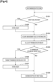
- the transmission unit 14 When receiving a credit signal in step S101, the transmission unit 14 updates the data of the credit management unit in step S102. In step S103, the transmission unit 14 acquires a measurement result of the internal state measured by the internal state measurement unit 11. In step S104, the transmission unit 14 calculates the transmission data amount.
- step S105 in a case where the transmission data amount calculated in step S104 is larger than 0, the transmission unit 14 transmits data if there is transmission waiting data in step S106, and updates the data of the credit management unit in step S107.
- step S108 the transmission unit 14 confirms the reception of the credit signal from the partner apparatus 2, and the process returns to step S101.
- the transmission unit 14 stores the communication data received from the partner apparatus 2 in the temporary data storage unit 16.
- the communication data is transferred to the processing device 20 via the bus control unit 15 and the internal bus 30.
- the temporary data storage unit 16 releases an area where the communication data is stored. Note that some data stored in the temporary data storage unit 16 may be processed by the communication control device 10.
- the transmission unit 14 updates the credit stored in the credit management unit according to the credit update method specified in the communication mode determined by the determination unit 13.
- the transmission unit 14 refers to the internal state of the communication apparatus 1 measured by the internal state measurement unit 11, the history of the credit, and the like, and updates the credit from the credit stored in the credit management unit.
- the transmission unit 14 transmits an updated credit signal to the partner apparatus 2.
- the transmission unit 14 When receiving a transfer completion signal of the communication data from the processing device 20 in step S201, the transmission unit 14 releases a corresponding buffer of the temporary data storage unit 16 in step S202.
- the transmission unit 14 When receiving communication data from the network 4 in step S203, the transmission unit 14 stores the communication data in the temporary data storage unit 16 in step S204.
- the transmission unit 14 transfers the data in the temporary data storage unit 16 in step S206. At this time, the transmission unit 14 transfers the data to an appropriate transfer destination such as the internal bus 30 or a circuit in the communication control device 10.
- step S207 the transmission unit 14 acquires a measurement result of the internal state of the internal state measurement unit 11.
- step S208 the transmission unit 14 calculates the credit from the measurement result of the internal state acquired in step S207 and the like.
- step S209 the transmission unit 14 determines whether the credit has been updated or not. In a case where the credit has not been updated, the process returns to step S201. In a case where the credit has been updated, the transmission unit 14 transmits a credit signal to the partner apparatus 2 in step S210.
- the transmission unit 14 can improve the data communication efficiency by releasing more credit and transmitting a credit signal to the partner apparatus 2.
- the communication system 5 can select and adaptively change the communication mode in consideration of not only the state of the network 4 but also the internal state of the communication apparatus 1. Therefore, high-speed communication is realized between communication apparatuses, and utilization efficiency of network resources can be improved.
- a sufficient buffer size can be secured in the temporary data storage unit 16 in the communication apparatus 1
- high-speed communication can be performed using a broadband communication path by increasing the maximum available transfer size depending on the transmission delay and the state of the network 4.
- a sufficient buffer size cannot be secured, it is possible to improve the error tolerance or reduce the used frequency by changing the communication mode such as the modulation mode and the used frequency, for example, and it is therefore possible to reduce the retransmission cost or realize efficient use of the frequency resources.
- a communication apparatuses 1a according to the first modified example will be described with reference to Fig. 6 .
- the partner apparatus 2 illustrated in Fig. 1 may have a similar configuration illustrated in Fig. 6 .
- the communication apparatus 1a illustrated in Fig. 6 is different from the communication apparatus 1 illustrated in Fig. 2 in that an internal state measurement unit 21, a network state measurement unit 22, and a determination unit 23 are not provided in a communication control device 10a but are connected with the internal bus 30.
- the internal state measurement unit 21, the network state measurement unit 22, and the determination unit 23 may be implemented by processing a program by using the CPU 901, or may be implemented by a dedicated circuit or the like.
- some of the internal state measurement unit 21, the network state measurement unit 22, and the determination unit 23 may be mounted on the communication control device 10a, and some thereof may be mounted on a device other than the communication control device 10a connected with the internal bus 30.
- the control signal interface 17 of the communication control device 10a controls transmission and reception of data between the transmission unit 14 and the internal state measurement unit 21, the network state measurement unit 22, or the determination unit 23 via the internal bus 30.
- some functions performed by the transmission unit 14, for example, a function of calculating the transmission data amount or managing the credit may be implemented not in the communication control device 10a but by a device connected with the internal bus 30.
- the device connected with the internal bus 30 may be the CPU 901, or a device other than the CPU 901 that controls the communication control device 10a.
- Some of the plurality of functions performed by the transmission unit 14 may be implemented by the CPU 901, and some of the functions may be implemented by a device that controls the communication control device 10a.
- a temporary data storage unit 16 mounted on the communication control device 10a may be mounted on a memory or the like connected with the internal bus 30.
- the internal state measurement unit 21, the network state measurement unit 22, or the determination unit 23 may be implemented in the communication apparatus 1a by any means or device.
- the data processing apparatus 6 that processes communication data is connected with a network 4 via a relay apparatus 7.
- the data processing apparatus 6 is connected with the relay apparatus 7.
- the relay apparatus 7 is connected with the data processing apparatus 6 and the network 4.
- the data processing apparatus 6 will be described with reference to Fig. 8 .
- the data processing apparatus 6 includes a processing unit 61 and a communication unit 62.
- the processing unit 61 processes communication data to be transmitted to and received from a partner apparatus.
- the communication unit 62 communicates with the relay apparatus 7.
- the communication unit 62 may be a general communication control device such as an NIC, and may not have the function of determining a communication mode described in the embodiment of the present invention.
- the relay apparatus 7 will be described with reference to Fig. 9 .
- the relay apparatus 7 includes the communication control device 70, a communication unit 90, and an internal bus 80.
- the communication control device 70 has a function similar to that of the communication control device 10 of the communication apparatus 1 described with reference to Fig. 2 .
- Each of an internal state measurement unit 71, a network state measurement unit 72, a determination unit 73, a transmission unit 74, a bus control unit 75, and a temporary data storage unit 76 of the communication control device 70 corresponds to each of the internal state measurement unit 11, the network state measurement unit 12, the determination unit 13, the transmission unit 14, the bus control unit 15, and the temporary data storage unit 16 of the communication control device 10 described with reference to Fig. 2 .
- the communication unit 90 communicates with the data processing apparatuses 6.
- the communication unit 90 may be a general communication control device such as an NIC, and may not have the function of determining a communication mode described in the embodiment of the present invention.
- the transmission unit 74 of the relay apparatus 7 transmits communication data to the partner apparatus 2 in the communication mode determined by the determination unit 73.
- the communication unit 90 transmits the communication data transmitted by the transmission unit 74 to the data processing apparatus 6.
- the relay apparatuses 7 that are connected via the network 4 communicate with each other in the communication method according to the embodiment of the present invention, specifically, in a communication mode selected from the internal states between the data processing apparatuses 6 and the relay apparatuses 7.
- the data processing apparatuses 6 and the relay apparatuses 7 communicate with each other by a general communication method. According to such a communication system 5a, it is possible to increase the utilization efficiency of network resources and respective apparatuses such as the data processing apparatuses 6 and the relay apparatuses 7 and to thereby realize high-speed communication by using the communication method according to the embodiment of the present invention without modifying a conventional data processing apparatus 6.
- the relay apparatus 7 may include a plurality of general communication control devices, and each communication control device may be connected with a plurality of data processing apparatuses 6. Therefore, the relay apparatus 7 can communicate with the plurality of data processing apparatuses 6 in the communication mode determined from the internal states.
- a communication method according to the second modified example will be described with reference to Fig. 10 .
- a case where a data processing apparatus 6a transmits data to a data processing apparatus 6b will be described.
- the data processing apparatus 6a is connected with a relay apparatus 7a.
- the data processing apparatus 6b is connected with a relay apparatus 7b.
- the relay apparatuses 7a and 7b are connected with the network 4.
- it is assumed that the communication mode is already shared by the relay apparatus 7a and the relay apparatus 7b.
- a communication unit 62a of the data processing apparatus 6a transmits communication data to the relay apparatus 7a.
- a communication unit 90a of the relay apparatus 7a stores the received communication data in the temporary data storage unit 76 of a communication control device 70a.
- the communication unit 90a returns a data reception response to the communication unit 62a of the data processing apparatus 6a.
- the data reception response may be a credit release signal.
- the communication control device 70a transmits the communication data to a communication control device 70b of the relay apparatus 7b via the network 4.
- step S505 the communication control device 70b of the relay apparatus 7b transfers the communication data to a communication unit 90b.
- the communication unit 90b transmits the communication data to a communication unit 62b of the data processing apparatus 6b.
- step S507 the communication unit 62b transmits a reception confirmation to the communication unit 90b.
- step S508 the communication unit 90b transmits a reception confirmation to the communication control device 70b.
- step S509 the communication control device 70b transmits a credit update signal to the communication control device 70a of the relay apparatus 7a.
- the communication control device 70a of the relay apparatus 7a When receiving the credit update signal, the communication control device 70a of the relay apparatus 7a deletes the communication data stored in the temporary data storage unit 76 and releases the buffer.
- the internal state measurement unit 71, the network state measurement unit 72, or the determination unit 73 may be implemented in the communication apparatus 1a by any means or device. Specifically, the internal state measurement unit 71, the network state measurement unit 72, or the determination unit 73 may be implemented not in the communication control device 70 but by the CPU 901, a dedicated circuit, or the like connected with the internal bus 80. Some functions performed by the transmission unit 74, for example, a function of calculating the transmission data amount or managing the credit may be implemented not in the communication control device 70 but by a device connected with the internal bus 80.
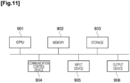
- Each of the communication apparatus 1, the data processing apparatus 6, and the relay apparatus 7 of the present embodiment described above uses, for example, a general-purpose computer system including the central processing unit (CPU) 901, a memory 902, a storage 903 (hard disk drive (HDD) or solid state drive (SSD)), a communication control device 904, an input device 905, and an output device 906.
- the CPU 901 executes a program loaded on the memory 902, thereby implementing the respective functions of the communication apparatus 1, the data processing apparatus 6, and the relay apparatus 7.
- each of the communication apparatus 1, the data processing apparatus 6, and the relay apparatus 7 may be implemented by one computer or may be implemented by a plurality of computers. Moreover, each of the communication apparatus 1, the data processing apparatus 6, and the relay apparatus 7 may be a virtual machine mounted on a computer.
- the program for each of the communication apparatus 1, the data processing apparatus 6, and the relay apparatus 7 can be stored in a computer-readable recording medium such as an HDD, an SSD, a universal serial bus (USB) memory, a compact disc (CD), or a digital versatile disc (DVD), or can be distributed via a network.
- a computer-readable recording medium such as an HDD, an SSD, a universal serial bus (USB) memory, a compact disc (CD), or a digital versatile disc (DVD), or can be distributed via a network.
Landscapes
- Engineering & Computer Science (AREA)
- Computer Networks & Wireless Communication (AREA)
- Signal Processing (AREA)
- Environmental & Geological Engineering (AREA)
- Computer Security & Cryptography (AREA)
- Communication Control (AREA)
Abstract
Description
- The present invention relates to a communication apparatus, a relay apparatus, a communication system, a communication method, and a program.
- With the progress of communication technology, provision of a new network for connecting a wide band and a long distance has been studied. Conventionally, a system has been studied in which an apparatus such as a transponder mounted on an optical transmission system is mounted on a client system such as a server in a new network. In such a system, an electrical signal reaches a server or the like of a communication partner without being subjected to electro-optical conversion during transmission.
- Generally, in an optical transmission system, there is a technique for suppressing network resources such as frequencies and establishing a high-speed transmission path by selecting an optimum communication mode from a network state (refer to
Patent Literature 1 and Patent Literature 2). The network state is a distance, signal quality, or the like. The communication mode is a modulation method, a baud rate, the number of carriers, or the like. With such technology, it is possible to realize long-distance and high-speed communication between communication apparatuses with fewer network resources. - Examples of an existing communication protocol include Ethernet, TCP/IP (Transmission Control Protocol/Internet Protocol), InfiniBand, and PCI (Peripheral Component Interconnect) Express.
-
- Patent Literature 1:
US 8,964,581 - Patent Literature 2:
WO 2020/031514 A - However, there is a possibility that long-distance and high-speed data communication cannot be realized by an existing communication protocol. With the recent speeding up of networks, a bottleneck in a network between communication apparatuses is eliminated, and a bottleneck tends to occur in a communication apparatus. However, since an existing communication protocol does not assume a situation in which a communication bottleneck occurs in a communication apparatus, the actual transfer speed may be significantly lower than that in a band available in the network. Moreover, even if the transmission system selects an optimum communication mode, utilization efficiency of network resources may be decreased in a case where the communication apparatus cannot efficiently use the communication mode.
- The present invention has been made in view of the above circumstances, and an object thereof is to provide a technique capable of realizing high-speed communication by selecting a communication mode in consideration of a state of a communication apparatus.
- A communication apparatus according to an aspect of the present invention includes: a processing device that processes communication data to be transmitted to and received from a partner apparatus; a transmission unit that transmits the communication data to the partner apparatus; an internal state measurement unit that measures a state related to transmission of the communication data between the processing device and the transmission unit; and a determination unit that determines a communication mode in communication with the partner apparatus from the state, in which the transmission unit transmits the communication data to the partner apparatus in the determined communication mode.
- A relay apparatus according to an aspect of the present invention includes: a communication unit that communicates with a processing device that processes communication data to be transmitted to and received from a partner apparatus; a transmission unit that transmits the communication data to the partner apparatus; an internal state measurement unit that measures a state related to transmission of the communication data between the processing device and the transmission unit; and a determination unit that determines a communication mode in communication with the partner apparatus from the state, in which the transmission unit transmits the communication data to the partner apparatus in the determined communication mode, and the communication unit transmits the communication data transmitted by the transmission unit to the processing device.
- A communication system according to an aspect of the present invention includes: a processing device that processes communication data to be transmitted to and received from a partner apparatus; a transmission unit that transmits the communication data to the partner apparatus; a plurality of communication apparatus including an internal state measurement unit that measures a state related to transmission of the communication data between the processing device and the transmission unit; and a determination unit that determines a communication mode in communication between the communication apparatus and the partner apparatus from states measured in the plurality of communication apparatuses, in which the transmission unit transmits the communication data to the partner apparatus in the determined communication mode.
- A communication system according to an aspect of the present invention includes: a processing device that processes communication data to be transmitted to and received from a partner apparatus; and a relay apparatus connected with the processing device, in which the relay apparatus includes: a communication unit that communicates with the processing device; a transmission unit that transmits the communication data to the partner apparatus; an internal state measurement unit that measures a state related to transmission of the communication data between the processing device and the transmission unit; and a determination unit that determines a communication mode in communication with the partner apparatus from the state, the transmission unit transmits the communication data to the partner apparatus in the determined communication mode, and the communication unit transmits the communication data transmitted by the transmission unit to the processing device.
- A communication method according to an aspect of the present invention includes: a step of measuring, by a communication apparatus, a state related to transmission of communication data between a processing device that processes the communication data to be transmitted to and received from a partner apparatus, and a transmission unit that transmits the communication data to the partner apparatus; a determination unit of determining, by the communication apparatus, a communication mode in communication between the communication apparatus and the partner apparatus from the measured state; and a step of transmitting, by the communication apparatus, the communication data to the partner apparatus in the determined communication mode in the transmission unit.
- An aspect of the present invention is a program for causing a computer to function as the communication apparatus or the relay apparatus.
- According to the present invention, it is possible to provide a technique capable of realizing high-speed communication by selecting a communication mode in consideration of a state of a communication apparatus.
-
- [
Figure 1] Fig. 1 is a diagram for explaining a system configuration of a communication system according to an embodiment of the present invention. - [
Figure 2] Fig. 2 is a block diagram illustrating a configuration of a communication apparatus according to an embodiment of the present invention. - [
Figure 3] Fig. 3 is a sequence diagram for explaining a communication method according to an embodiment of the present invention. - [
Figure 4] Fig. 4 is a flowchart for explaining data transmission processing in credit based flow control. - [
Figure 5] Fig. 5 is a flowchart for explaining data reception processing in credit based flow control. - [
Figure 6] Fig. 6 is a block diagram illustrating a configuration of a communication apparatus according to a first modified example. - [
Figure 7] Fig. 7 is a diagram for explaining a system configuration of a communication system according to a second modified example. - [
Figure 8] Fig. 8 is a block diagram illustrating a configuration of a processing device according to the second modified example. - [
Figure 9] Fig. 9 is a block diagram illustrating a configuration of a relay apparatus according to the second modified example. - [
Figure 10] Fig. 10 is a sequence diagram for explaining a communication method according to the second modified example. - [
Figure 11] Fig. 11 is a diagram for explaining a hardware configuration of a computer used for each of a communication apparatus, a processing device, and a relay apparatus. - Hereinafter, an embodiment of the present invention will be described with reference to the drawings. In the drawings, the same parts are denoted by the same reference signs, and description thereof will be omitted.
- A
communication system 5 in which acommunication apparatus 1 according to an embodiment of the present invention is used will be described with reference toFig. 1 . Thecommunication system 5 includes a plurality ofcommunication apparatuses 1 according to the embodiment of the present invention. The plurality ofcommunication apparatuses 1 can communicate with each other in a plurality of communication modes through anetwork 4 connecting the plurality ofcommunication apparatuses 1. A communication mode is a transmission mode in a predetermined communication protocol, and includes a modulation method, an error correcting system, a baud rate, the number of carriers, and the like. In the case of a communication protocol capable of performing credit based flow control, the communication mode may include a maximum transfer size, a buffer size secured by thepartner apparatus 2, a credit update method, a credit transmission method, and a transmission data amount calculation method. - The
communication system 5 adaptively changes the communication mode in consideration of not only the situation of thenetwork 4 but also the situation of eachcommunication apparatus 1. Thecommunication system 5 increases utilization efficiency of resources of thecommunication apparatuses 1 and resources of the network, and realizes high-speed communication. - In the embodiment of the present invention, a case will be described in which a plurality of
communication apparatuses 1 having similar functions mutually transmit and receive communication data. In the embodiment of the present invention, the communication data is data transmitted and received between the plurality ofcommunication apparatuses 1. A packet in which communication data is set as a payload may be transmitted and received. The plurality ofcommunication apparatuses 1 may be described as acommunication apparatus 1 and apartner apparatus 2 that is a communication partner of thecommunication apparatus 1. - As illustrated in
Fig. 1 , thecommunication apparatus 1 includes acommunication control device 10, aprocessing device 20, and aninternal bus 30. Thecommunication control device 10 and theprocessing device 20 are communicably connected with each other via theinternal bus 30. - The
communication control device 10 serves as an interface when thecommunication apparatus 1 communicates with thepartner apparatus 2 via thenetwork 4. Thecommunication control device 10 is, for example, NIC (Network Interface Card). In the embodiment of the present invention, thecommunication control device 10 has a function for determining a communication mode in communication with thepartner apparatus 2 in addition to a function of a general NIC. - The
processing device 20 processes the communication data. Theprocessing device 20 generates communication data, and causes thecommunication control device 10 to transmit the generated communication data to thepartner apparatus 2 via theinternal bus 30. Alternatively, theprocessing device 20 acquires communication data from thecommunication control device 10 via theinternal bus 30, and processes the acquired communication data. - The
processing device 20 may be any device as long as the device is connected with theinternal bus 30 and processes communication data. Theprocessing device 20 is, for example, a processing unit implemented by executing a predetermined program in aCPU 901. Theprocessing device 20 may be a dedicated circuit such as FGPA (Field Programmable Gate Array), GPU (Graphics Processing Unit), or TPU (Tensor Processing Unit). - The
internal bus 30 is a path for thecommunication control device 10 and theprocessing device 20 to transmit and receive data. - The
communication control device 10 will be described. Thecommunication control device 10 includes an internalstate measurement unit 11, a networkstate measurement unit 12, adetermination unit 13, atransmission unit 14, abus control unit 15, and a temporarydata storage unit 16. - The internal
state measurement unit 11 measures a state related to transmission of communication data between theprocessing device 20 and thetransmission unit 14. The internalstate measurement unit 11 measures the state of theinternal bus 30 and the state of each device connected with theinternal bus 30, and specifies the quality of transmission of the communication data. A state of theinternal bus 30 may be a maximum transfer band at the time of measurement, a congestion state, a delay from thetransmission unit 14 to each device, a loss rate, jitter, or the like. A state of each device is a maximum transfer speed, an error correction capability, or the like. Each data measured by the internalstate measurement unit 11 is taken into consideration by thedetermination unit 13. - The network
state measurement unit 12 measures the state of thenetwork 4 between thecommunication apparatus 1 and thepartner apparatus 2. The state of thenetwork 4 includes transmission quality such as delay, a loss rate, jitter, or OSNR (Optical Signal-to-Noise Ratio). Each data measured by the networkstate measurement unit 12 is taken into consideration by thedetermination unit 13. - The
determination unit 13 determines a communication mode in communication with thepartner apparatus 2 from the state measured by the internalstate measurement unit 11. - For example, the
determination unit 13 specifies a part inside thecommunication apparatus 1, which is the bottleneck, by using the internalstate measurement unit 11, and extracts communication modes capable of realizing a communication speed corresponding to the bottleneck. Thedetermination unit 13 determines an optimum communication mode from the extracted communication modes. - The
determination unit 13 further determines a communication mode from the state related to transmission of the communication data in thepartner apparatus 2. Thedetermination unit 13 may further determine a communication mode in consideration of the state of thenetwork 4 measured by the networkstate measurement unit 12 and the free capacity in the temporarydata storage unit 16. Thedetermination unit 13 selects a communication mode available in thecommunication apparatus 1 and thepartner apparatus 2 from the state in thecommunication apparatus 1, the state in thepartner apparatus 2, and the like, and determines an optimum communication mode from the communication modes available in thecommunication apparatus 1 and thepartner apparatus 2 on the basis of a predetermined index. The index for determining the optimum communication mode is preliminarily given by the administrator of thenetwork 4, the administrator of thecommunication apparatus 1, or the like. - The
determination unit 13 may adopt any method as long as it is possible to determine an optimum communication mode from the state in thecommunication apparatus 1 and the state in thepartner apparatus 2 and share the determined communication mode with thepartner apparatus 2. For example, thedetermination unit 13 of thecommunication apparatus 1 may acquire information on thepartner apparatus 2 and determine an optimum communication mode from the state in thecommunication apparatus 1 and the information acquired from thepartner apparatus 2. In this case, thedetermination unit 13 transmits the determined communication mode to thepartner apparatus 2. The state of thepartner apparatus 2 acquired by thedetermination unit 13 may be internal measurement data measured in thepartner apparatus 2 or a list of communication modes available by thepartner apparatus 2. As another method, thedetermination unit 13 of thecommunication apparatus 1 may transmit internal information acquired by the internalstate measurement unit 11 to thepartner apparatus 2, and determine the communication mode notified by from thepartner apparatus 2 as the optimum communication mode. Here, the internal information transmitted by thedetermination unit 13 to the partner apparatus may be measurement data by the internalstate measurement unit 11 or a list of communication modes available by thecommunication apparatus 1. - When the
determination unit 13 determines a communication mode to be used for communication with thepartner apparatus 2, resources inside thecommunication apparatus 1 necessary for executing this communication mode are secured. Specifically, thedetermination unit 13 secures an area of the temporarydata storage unit 16, secures or occupies a band of theinternal bus 30, or occupies a device of each device such as theprocessing device 20 or the like. If possible by using the specification of theinternal bus 30, thedetermination unit 13 may occupy or secure a band of theinternal bus 30. - The
transmission unit 14 prepares for securing resources and the like inside thecommunication apparatus 1 in order to perform communication in the communication mode determined by thedetermination unit 13. Thetransmission unit 14 transmits communication data to thepartner apparatus 2 in the communication mode determined by thedetermination unit 13. - The
bus control unit 15 is an interface through which thecommunication control device 10 is connected with theinternal bus 30. Thebus control unit 15 receives data transmitted from theprocessing device 20 and stores the data in the temporarydata storage unit 16, or transfers data stored in the temporarydata storage unit 16 to theprocessing device 20. Thebus control unit 15 further secures resources in the respective devices such as theinternal bus 30 and theprocessing device 20 under the control of thedetermination unit 13. - The temporary
data storage unit 16 is a memory area that temporarily stores communication data or the like transmitted and received by thetransmission unit 14. - A communication method according to an embodiment of the present invention will be described with reference to
Fig. 3 . Although a case where twocommunication apparatuses 1 simultaneously perform the same processing will be described in the example illustrated inFig. 3 , what is required is that twocommunication apparatuses 1 can agree on a communication mode to be used among communication modes selectable by therespective communication apparatuses 1, and the processing may be executed in any procedure. - In step S1, each
communication apparatus 1 measures the state of thenetwork 4. In step S2, eachcommunication apparatus 1 measures the state of the internal bus of each apparatus. In step S3, eachcommunication apparatus 1 measures the state of theprocessing device 20 of each apparatus. - In step S4, each
communication apparatus 1 lists available communication modes from the measurement results of steps S1 to S3. In step S5, eachcommunication apparatus 1 exchanges communication modes selectable by eachcommunication apparatus 1. In step S6, eachcommunication apparatus 1 selects an available communication mode. In step S7, thecommunication apparatuses 1 notify each other of a communication mode to be used, and agree on the communication mode to be used. - In step S8, each
communication apparatus 1 makes necessary settings for the communication mode agreed in step S7, and secures resources. In step S9, eachcommunication apparatus 1 starts communication in the communication mode agreed in step S7. - The
communication apparatus 1 according to the embodiment of the present invention can select a communication mode in consideration of the internal state of thecommunication apparatus 1 in addition to the state of thenetwork 4. Thecommunication system 5 according to the embodiment of the present invention can realize high-speed communication by effectively using resources in thecommunication system 5. - For example, as the communication mode, an optimum maximum transfer size is set in a communication system capable of performing high-speed and long-distance communication. For example, in a case where the transmission delay is 100 ms and the transmission speed can be 100 Gbps, the
communication apparatus 1 sets a value exceeding 100 Gbps * 100 ms = 1.25 Gbyte as the maximum transfer size. Moreover, thecommunication apparatus 1 secures a buffer exceeding the maximum transfer size. As a result, thecommunication apparatuses 1 can communicate with each other by taking advantage of the transmission speed that can be provided by thecommunication system 5. - Moreover, in a case where the
communication apparatus 1 lacks resources corresponding to the speed provided by thecommunication system 5, an excessive speed of thecommunication system 5 can be suppressed by changing the modulation method of thecommunication system 5. Thecommunication system 5 can efficiently use the resources of thenetwork 4 by further improving the error tolerance or reducing the frequencies to be used. - Transmission processing and reception processing will be described as processing of the
transmission unit 14 in a case where a communication protocol capable of credit based flow control is used. Thedetermination unit 13 also determines a credit update method, a transmission data amount calculation method, and the like as communication modes. Moreover, thecommunication control device 10 includes a credit management unit (not illustrated). The credit management unit manages data related to credit based flow control such as credit. - First, transmission processing will be described. The communication data transmitted by the
transmission unit 14 is transferred from theprocessing device 20 to thecommunication control device 10 and stored in the temporarydata storage unit 16. - When receiving a credit signal from the
partner apparatus 2, thetransmission unit 14 updates the credit stored in the credit management unit by the credit update method specified by the content of the credit signal and the communication mode determined by thedetermination unit 13. The credit signal received from thepartner apparatus 2 includes information indicating the amount of data receivable by the partner apparatus 2 (Kung & Morris, Credit-based flow control for ATM networks, IEEE Network, 9(2), 40-48 (1995)). Moreover, the credit signal may include an internal state in thepartner apparatus 2. - The
transmission unit 14 calculates the transmission data amount. The data amount is calculated from a history of the credit value and a measurement result acquired from the internalstate measurement unit 11 in addition to a transmission data amount calculation method specified in the communication mode determined by thedetermination unit 13 and the current value of the credit stored in the credit management unit. - In a case where the transmission data amount is larger than 0 and there is transmission waiting data, the
transmission unit 14 transmits the data. After the data transmission, thetransmission unit 14 updates the credit value of the credit management unit. - In the calculation of the transmission data amount, the
transmission unit 14 regards the free capacity of the internal buffer of thepartner apparatus 2 as the transmission data amount, and transmits data within the free capacity of the internal buffer of thepartner apparatus 2. For example, thetransmission unit 14 may estimate the free capacity of the internal buffer of thepartner apparatus 2 from the release notification history of the credit signal received from the partner apparatus, and transmit data within the estimated free capacity. Thetransmission unit 14 may transmit, for example, an amount exceeding the receivable data amount notified by thepartner apparatus 2 as long as the amount is within the estimated free capacity of the internal buffer. Moreover, in a case where the retransmission cost is estimated to be small, or in a case where it is estimated that there is a free capacity in the internal buffer of thepartner apparatus 2 by the time the communication data reaches thepartner apparatus 2, thetransmission unit 14 may transmit an amount exceeding the receivable data amount notified by thepartner apparatus 2. As a result, thecommunication system 5 can improve the efficiency of data communication in the credit based flow control. - Processing related to data transmission performed by the
transmission unit 14 in the credit based flow control will be described with reference toFig. 4 . - When receiving a credit signal in step S101, the
transmission unit 14 updates the data of the credit management unit in step S102. In step S103, thetransmission unit 14 acquires a measurement result of the internal state measured by the internalstate measurement unit 11. In step S104, thetransmission unit 14 calculates the transmission data amount. - In step S105, in a case where the transmission data amount calculated in step S104 is larger than 0, the
transmission unit 14 transmits data if there is transmission waiting data in step S106, and updates the data of the credit management unit in step S107. In step S108, thetransmission unit 14 confirms the reception of the credit signal from thepartner apparatus 2, and the process returns to step S101. - Next, reception processing will be described.
- The
transmission unit 14 stores the communication data received from thepartner apparatus 2 in the temporarydata storage unit 16. The communication data is transferred to theprocessing device 20 via thebus control unit 15 and theinternal bus 30. When receiving a transfer completion signal of the communication data from theprocessing device 20, the temporarydata storage unit 16 releases an area where the communication data is stored. Note that some data stored in the temporarydata storage unit 16 may be processed by thecommunication control device 10. - The
transmission unit 14 updates the credit stored in the credit management unit according to the credit update method specified in the communication mode determined by thedetermination unit 13. Thetransmission unit 14 refers to the internal state of thecommunication apparatus 1 measured by the internalstate measurement unit 11, the history of the credit, and the like, and updates the credit from the credit stored in the credit management unit. When the credit is updated, thetransmission unit 14 transmits an updated credit signal to thepartner apparatus 2. - Processing related to data reception performed by the
transmission unit 14 in the credit based flow control will be described with reference toFig. 5 . - When receiving a transfer completion signal of the communication data from the
processing device 20 in step S201, thetransmission unit 14 releases a corresponding buffer of the temporarydata storage unit 16 in step S202. - When receiving communication data from the
network 4 in step S203, thetransmission unit 14 stores the communication data in the temporarydata storage unit 16 in step S204. - In a case where there is data in the temporary
data storage unit 16 in step S205, thetransmission unit 14 transfers the data in the temporarydata storage unit 16 in step S206. At this time, thetransmission unit 14 transfers the data to an appropriate transfer destination such as theinternal bus 30 or a circuit in thecommunication control device 10. - In step S207, the
transmission unit 14 acquires a measurement result of the internal state of the internalstate measurement unit 11. In step S208, thetransmission unit 14 calculates the credit from the measurement result of the internal state acquired in step S207 and the like. - In step S209, the
transmission unit 14 determines whether the credit has been updated or not. In a case where the credit has not been updated, the process returns to step S201. In a case where the credit has been updated, thetransmission unit 14 transmits a credit signal to thepartner apparatus 2 in step S210. - Here, even in a case where the free capacity of the temporary
data storage unit 16 is insufficient from the history of the credit, the state of thenetwork 4, the internal state, and the like, transfer of the communication data to the internal bus may be expected when the communication data is received from thepartner apparatus 2. In that case, thetransmission unit 14 can improve the data communication efficiency by releasing more credit and transmitting a credit signal to thepartner apparatus 2. - In a conventional communication system, even if an appropriate communication mode is selected and a broadband communication path is established between communication apparatuses with a small number of network resources, a bottleneck tends to occur in the communication apparatuses. As a result, not only high-speed communication cannot be realized between communication apparatuses, but also utilization efficiency of network resources may be decreased.
- On the other hand, the
communication system 5 according to the embodiment of the present invention can select and adaptively change the communication mode in consideration of not only the state of thenetwork 4 but also the internal state of thecommunication apparatus 1. Therefore, high-speed communication is realized between communication apparatuses, and utilization efficiency of network resources can be improved. - For example, in a case where a sufficient buffer size can be secured in the temporary
data storage unit 16 in thecommunication apparatus 1, high-speed communication can be performed using a broadband communication path by increasing the maximum available transfer size depending on the transmission delay and the state of thenetwork 4. On the other hand, in a case where a sufficient buffer size cannot be secured, it is possible to improve the error tolerance or reduce the used frequency by changing the communication mode such as the modulation mode and the used frequency, for example, and it is therefore possible to reduce the retransmission cost or realize efficient use of the frequency resources. - A communication apparatuses 1a according to the first modified example will be described with reference to
Fig. 6 . Thepartner apparatus 2 illustrated inFig. 1 may have a similar configuration illustrated inFig. 6 . - The communication apparatus 1a illustrated in
Fig. 6 is different from thecommunication apparatus 1 illustrated inFig. 2 in that an internalstate measurement unit 21, a networkstate measurement unit 22, and adetermination unit 23 are not provided in acommunication control device 10a but are connected with theinternal bus 30. The internalstate measurement unit 21, the networkstate measurement unit 22, and thedetermination unit 23 may be implemented by processing a program by using theCPU 901, or may be implemented by a dedicated circuit or the like. Moreover, some of the internalstate measurement unit 21, the networkstate measurement unit 22, and thedetermination unit 23 may be mounted on thecommunication control device 10a, and some thereof may be mounted on a device other than thecommunication control device 10a connected with theinternal bus 30. - In a case where the internal
state measurement unit 21, the networkstate measurement unit 22, or thedetermination unit 23 is connected with theinternal bus 30, thecontrol signal interface 17 of thecommunication control device 10a controls transmission and reception of data between thetransmission unit 14 and the internalstate measurement unit 21, the networkstate measurement unit 22, or thedetermination unit 23 via theinternal bus 30. - Moreover, some functions performed by the
transmission unit 14, for example, a function of calculating the transmission data amount or managing the credit may be implemented not in thecommunication control device 10a but by a device connected with theinternal bus 30. Here, the device connected with theinternal bus 30 may be theCPU 901, or a device other than theCPU 901 that controls thecommunication control device 10a. Some of the plurality of functions performed by thetransmission unit 14 may be implemented by theCPU 901, and some of the functions may be implemented by a device that controls thecommunication control device 10a. Furthermore, a temporarydata storage unit 16 mounted on thecommunication control device 10a may be mounted on a memory or the like connected with theinternal bus 30. - As described above, the internal
state measurement unit 21, the networkstate measurement unit 22, or thedetermination unit 23 may be implemented in the communication apparatus 1a by any means or device. - A case has been described in which the
processing device 20 that processes communication data and thecommunication control device 10 having a function of selecting a communication mode are mounted on the same device in the embodiment of the present invention. In the second modified example, a case will be described in which adata processing apparatus 6 that processes communication data and acommunication control device 70 are mounted on different devices. - As illustrated in
Fig. 7 , in acommunication system 5a according to the second modified example, thedata processing apparatus 6 that processes communication data is connected with anetwork 4 via arelay apparatus 7. Thedata processing apparatus 6 is connected with therelay apparatus 7. Therelay apparatus 7 is connected with thedata processing apparatus 6 and thenetwork 4. - The
data processing apparatus 6 will be described with reference toFig. 8 . Thedata processing apparatus 6 includes aprocessing unit 61 and acommunication unit 62. Theprocessing unit 61 processes communication data to be transmitted to and received from a partner apparatus. Thecommunication unit 62 communicates with therelay apparatus 7. Thecommunication unit 62 may be a general communication control device such as an NIC, and may not have the function of determining a communication mode described in the embodiment of the present invention. - The
relay apparatus 7 will be described with reference toFig. 9 . Therelay apparatus 7 includes thecommunication control device 70, acommunication unit 90, and an internal bus 80. Thecommunication control device 70 has a function similar to that of thecommunication control device 10 of thecommunication apparatus 1 described with reference toFig. 2 . Each of an internalstate measurement unit 71, a network state measurement unit 72, adetermination unit 73, atransmission unit 74, abus control unit 75, and a temporarydata storage unit 76 of thecommunication control device 70 corresponds to each of the internalstate measurement unit 11, the networkstate measurement unit 12, thedetermination unit 13, thetransmission unit 14, thebus control unit 15, and the temporarydata storage unit 16 of thecommunication control device 10 described with reference toFig. 2 . Thecommunication unit 90 communicates with thedata processing apparatuses 6. Thecommunication unit 90 may be a general communication control device such as an NIC, and may not have the function of determining a communication mode described in the embodiment of the present invention. - The
transmission unit 74 of therelay apparatus 7 transmits communication data to thepartner apparatus 2 in the communication mode determined by thedetermination unit 73. Thecommunication unit 90 transmits the communication data transmitted by thetransmission unit 74 to thedata processing apparatus 6. - In the
communication system 5a, therelay apparatuses 7 that are connected via thenetwork 4 communicate with each other in the communication method according to the embodiment of the present invention, specifically, in a communication mode selected from the internal states between thedata processing apparatuses 6 and therelay apparatuses 7. Thedata processing apparatuses 6 and therelay apparatuses 7 communicate with each other by a general communication method. According to such acommunication system 5a, it is possible to increase the utilization efficiency of network resources and respective apparatuses such as thedata processing apparatuses 6 and therelay apparatuses 7 and to thereby realize high-speed communication by using the communication method according to the embodiment of the present invention without modifying a conventionaldata processing apparatus 6. Moreover, therelay apparatus 7 may include a plurality of general communication control devices, and each communication control device may be connected with a plurality ofdata processing apparatuses 6. Therefore, therelay apparatus 7 can communicate with the plurality ofdata processing apparatuses 6 in the communication mode determined from the internal states. - A communication method according to the second modified example will be described with reference to
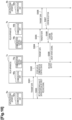
Fig. 10 . In the example illustrated inFig. 10 , a case where adata processing apparatus 6a transmits data to adata processing apparatus 6b will be described. Thedata processing apparatus 6a is connected with arelay apparatus 7a. Thedata processing apparatus 6b is connected with arelay apparatus 7b. Therelay apparatuses network 4. Moreover, it is assumed that the communication mode is already shared by therelay apparatus 7a and therelay apparatus 7b. - In step S501, a
communication unit 62a of thedata processing apparatus 6a transmits communication data to therelay apparatus 7a. In step S502, acommunication unit 90a of therelay apparatus 7a stores the received communication data in the temporarydata storage unit 76 of acommunication control device 70a. In step S503, thecommunication unit 90a returns a data reception response to thecommunication unit 62a of thedata processing apparatus 6a. In a case where the credit based flow control is performed between thecommunication unit 90a and thecommunication unit 62a, the data reception response may be a credit release signal. In step S504, thecommunication control device 70a transmits the communication data to acommunication control device 70b of therelay apparatus 7b via thenetwork 4. - In step S505, the
communication control device 70b of therelay apparatus 7b transfers the communication data to acommunication unit 90b. In step S506, thecommunication unit 90b transmits the communication data to acommunication unit 62b of thedata processing apparatus 6b. In step S507, thecommunication unit 62b transmits a reception confirmation to thecommunication unit 90b. In step S508, thecommunication unit 90b transmits a reception confirmation to thecommunication control device 70b. In step S509, thecommunication control device 70b transmits a credit update signal to thecommunication control device 70a of therelay apparatus 7a. - When receiving the credit update signal, the
communication control device 70a of therelay apparatus 7a deletes the communication data stored in the temporarydata storage unit 76 and releases the buffer. - As described above, according to the
relay apparatus 7 according to the second modified example, it is possible to realize the communication method according to the embodiment of the present invention without modifying an existing processing device. - Also in the
relay apparatus 7 according to the second modified example, as described in the first modified example, the internalstate measurement unit 71, the network state measurement unit 72, or thedetermination unit 73 may be implemented in the communication apparatus 1a by any means or device. Specifically, the internalstate measurement unit 71, the network state measurement unit 72, or thedetermination unit 73 may be implemented not in thecommunication control device 70 but by theCPU 901, a dedicated circuit, or the like connected with the internal bus 80. Some functions performed by thetransmission unit 74, for example, a function of calculating the transmission data amount or managing the credit may be implemented not in thecommunication control device 70 but by a device connected with the internal bus 80. - Each of the
communication apparatus 1, thedata processing apparatus 6, and therelay apparatus 7 of the present embodiment described above uses, for example, a general-purpose computer system including the central processing unit (CPU) 901, amemory 902, a storage 903 (hard disk drive (HDD) or solid state drive (SSD)), acommunication control device 904, aninput device 905, and anoutput device 906. In the computer system, theCPU 901 executes a program loaded on thememory 902, thereby implementing the respective functions of thecommunication apparatus 1, thedata processing apparatus 6, and therelay apparatus 7. - Note that each of the
communication apparatus 1, thedata processing apparatus 6, and therelay apparatus 7 may be implemented by one computer or may be implemented by a plurality of computers. Moreover, each of thecommunication apparatus 1, thedata processing apparatus 6, and therelay apparatus 7 may be a virtual machine mounted on a computer. - The program for each of the
communication apparatus 1, thedata processing apparatus 6, and therelay apparatus 7 can be stored in a computer-readable recording medium such as an HDD, an SSD, a universal serial bus (USB) memory, a compact disc (CD), or a digital versatile disc (DVD), or can be distributed via a network. - Note that the present invention is not limited to the above embodiment, and various modifications can be made within the scope of the gist of the present invention.
-
- 1
- Communication apparatus
- 2
- Partner apparatus
- 4
- Network
- 5
- Communication system
- 6
- Data processing apparatus
- 7
- Relay apparatus
- 10
- Communication control device
- 11, 21
- Internal state measurement unit
- 12, 22
- Network state measurement unit
- 13, 23
- Determination unit
- 14
- Transmission unit
- 15
- Bus control unit
- 16
- Temporary data storage unit
- 17
- Control signal interface
- 20
- Processing device
- 30
- Internal bus
- 901
- CPU
- 902
- Memory
- 903
- Storage
- 904
- Communication control device
- 905
- Input device
- 906
- Output device
Claims (8)
- A communication apparatus comprising:a processing device that processes communication data to be transmitted to and received from a partner apparatus;a transmission unit that transmits the communication data to the partner apparatus;an internal state measurement unit that measures a state related to transmission of the communication data between the processing device and the transmission unit; anda determination unit that determines a communication mode in communication with the partner apparatus from the state,wherein the transmission unit transmits the communication data to the partner apparatus in the determined communication mode.
- The communication apparatus according to claim 1,
wherein the determination unit further determines the communication mode from a state related to transmission of communication data in the partner apparatus. - The communication apparatuses according to claim 1 or 2,
wherein the transmission unit transmits data within a free capacity of an internal buffer of the partner apparatus. - A relay apparatus comprising:a communication unit that communicates with a processing device that processes communication data to be transmitted to and received from a partner apparatus;a transmission unit that transmits the communication data to the partner apparatus;an internal state measurement unit that measures a state related to transmission of the communication data between the processing device and the transmission unit; anda determination unit that determines a communication mode in communication with the partner apparatus from the state,wherein the transmission unit transmits the communication data to the partner apparatus in the determined communication mode, andthe communication unit transmits the communication data transmitted by the transmission unit to the processing device.
- A communication system comprising:a processing device that processes communication data to be transmitted to and received from a partner apparatus;a transmission unit that transmits the communication data to the partner apparatus;a plurality of communication apparatuses including an internal state measurement unit that measures a state related to transmission of the communication data between the processing device and the transmission unit; anda determination unit that determines a communication mode in communication between the communication apparatus and the partner apparatus from states measured in the plurality of communication apparatuses,wherein the transmission unit transmits the communication data to the partner apparatus in the determined communication mode.
- A communication system comprising:a processing device that processes communication data to be transmitted to and received from a partner apparatus; anda relay apparatus connected with the processing device,wherein the relay apparatus includes:a communication unit that communicates with the processing device;a transmission unit that transmits the communication data to the partner apparatus;an internal state measurement unit that measures a state related to transmission of the communication data between the processing device and the transmission unit; anda determination unit that determines a communication mode in communication with the partner apparatus from the state,the transmission unit transmits the communication data to the partner apparatus in the determined communication mode, andthe communication unit transmits the communication data transmitted by the transmission unit to the processing device.
- A communication method comprising:a step of measuring, by a communication apparatus, a state related to transmission of communication data between a processing device that processes the communication data to be transmitted to and received from a partner apparatus, and a transmission unit that transmits the communication data to the partner apparatus;a determination unit of determining, by the communication apparatus, a communication mode in communication between the communication apparatus and the partner apparatus from the measured state; anda step of transmitting, by the communication apparatus, the communication data to the partner apparatus in the determined communication mode in the transmission unit.
- A program for causing a computer to function as the communication apparatus according to any one of claims 1 to 3 or the relay apparatus according to claim 4.
Applications Claiming Priority (1)
| Application Number | Priority Date | Filing Date | Title |
|---|---|---|---|
| PCT/JP2021/000803 WO2022153387A1 (en) | 2021-01-13 | 2021-01-13 | Communication device, relay device, communication system, communication method, and program |
Publications (3)
| Publication Number | Publication Date |
|---|---|
| EP4280467A1 true EP4280467A1 (en) | 2023-11-22 |
| EP4280467A4 EP4280467A4 (en) | 2024-10-09 |
| EP4280467B1 EP4280467B1 (en) | 2025-10-22 |
Family
ID=82446982
Family Applications (1)
| Application Number | Title | Priority Date | Filing Date |
|---|---|---|---|
| EP21919283.8A Active EP4280467B1 (en) | 2021-01-13 | 2021-01-13 | Communication device, communication system, communication method, and program |
Country Status (4)
| Country | Link |
|---|---|
| US (1) | US12341673B2 (en) |
| EP (1) | EP4280467B1 (en) |
| JP (1) | JP7506335B2 (en) |
| WO (1) | WO2022153387A1 (en) |
Family Cites Families (21)
| Publication number | Priority date | Publication date | Assignee | Title |
|---|---|---|---|---|
| JP2000269938A (en) | 1999-03-19 | 2000-09-29 | Kokusai Electric Co Ltd | Wireless communication method and wireless communication device |
| JP4032824B2 (en) * | 2002-05-22 | 2008-01-16 | ソニー株式会社 | Communication method and communication bridge device |
| JP2004297381A (en) * | 2003-03-26 | 2004-10-21 | Sony Corp | Wireless communication method and wireless communication relay device |
| US7599289B2 (en) * | 2005-05-13 | 2009-10-06 | Lockheed Martin Corporation | Electronic communication control |
| DE102005062575B4 (en) * | 2005-12-27 | 2009-02-12 | Oce Printing Systems Gmbh | Method and device for transmitting data via a data connection from a sender to a receiver by means of packets |
| WO2011030897A1 (en) | 2009-09-14 | 2011-03-17 | 日本電信電話株式会社 | Band-variable communication method, band-variable communication apparatus, transmission band deciding apparatus, transmission band deciding method, node apparatus, communication path setting system, and communication path setting method |
| JP5189111B2 (en) | 2010-01-07 | 2013-04-24 | 株式会社エヌ・ティ・ティ・ドコモ | Radio base station apparatus, radio communication system, and radio communication method |
| JP5593840B2 (en) * | 2010-05-28 | 2014-09-24 | 富士通株式会社 | Optical transmitter and optical receiver |
| JP5873980B2 (en) * | 2011-06-08 | 2016-03-01 | パナソニックIpマネジメント株式会社 | Communication apparatus and communication method |
| JP6060723B2 (en) * | 2013-02-21 | 2017-01-18 | 富士通株式会社 | COMMUNICATION SYSTEM, TRANSMITTER, AND COMMUNICATION CONTROL METHOD |
| JP6589276B2 (en) * | 2015-01-13 | 2019-10-16 | 富士通株式会社 | Optical transmission apparatus, optical transmission system, and transmission wavelength control method |
| JP2017163358A (en) * | 2016-03-09 | 2017-09-14 | 富士通株式会社 | Network management device, network system, network management method, and network management program |
| US10291311B2 (en) * | 2016-09-09 | 2019-05-14 | At&T Intellectual Property I, L.P. | Method and apparatus for mitigating a fault in a distributed antenna system |
| US10014971B2 (en) * | 2016-09-12 | 2018-07-03 | Fujitsu Limited | Credit based approach to calculating optical paths |
| JP6922275B2 (en) | 2017-03-10 | 2021-08-18 | 日本電気株式会社 | Network control method, control device, program |
| US10225008B1 (en) * | 2018-04-27 | 2019-03-05 | Fujitsu Limited | Systems and methods for reconfiguring an adaptive optical network when adding an optical path |
| US10389473B1 (en) * | 2018-04-27 | 2019-08-20 | Fujitsu Limited | Reach extension for optical networks through control of modulation formats and numbers of subcarriers |
| JP6939718B2 (en) * | 2018-06-26 | 2021-09-22 | 日本電信電話株式会社 | Network device and network device setting method |
| JP7152682B2 (en) | 2018-08-07 | 2022-10-13 | 日本電信電話株式会社 | Optical transmission system and transmission mode selection method |
| WO2021009814A1 (en) * | 2019-07-12 | 2021-01-21 | 日本電信電話株式会社 | Optical cross-connect device, optical transmission system, and method for detecting erroneous connection of optical transmission line |
| US20220311711A1 (en) * | 2021-09-23 | 2022-09-29 | Intel Corporation | Congestion control based on network telemetry |
-
2021
- 2021-01-13 JP JP2022574904A patent/JP7506335B2/en active Active
- 2021-01-13 US US18/270,935 patent/US12341673B2/en active Active
- 2021-01-13 WO PCT/JP2021/000803 patent/WO2022153387A1/en not_active Ceased
- 2021-01-13 EP EP21919283.8A patent/EP4280467B1/en active Active
Also Published As
| Publication number | Publication date |
|---|---|
| EP4280467A4 (en) | 2024-10-09 |
| JPWO2022153387A1 (en) | 2022-07-21 |
| US12341673B2 (en) | 2025-06-24 |
| JP7506335B2 (en) | 2024-06-26 |
| WO2022153387A1 (en) | 2022-07-21 |
| US20240064077A1 (en) | 2024-02-22 |
| EP4280467B1 (en) | 2025-10-22 |
Similar Documents
| Publication | Publication Date | Title |
|---|---|---|
| US8407364B2 (en) | Apparatus and method for providing a congestion measurement in a network | |
| US9185047B2 (en) | Hierarchical profiled scheduling and shaping | |
| US8824296B2 (en) | Handling congestion in a queue without discarding new messages received from a message sender | |
| EP3232638B1 (en) | Data transmission method, apparatus and system | |
| CN110225553B (en) | A data distribution method, device, and system | |
| EP3525406A1 (en) | Method and apparatus for determining tcp congestion window | |
| JPH03174848A (en) | Delay base rush evading method in computer network and device | |
| CN108494676A (en) | Data transmission method, device, data transmitting/receiving equipment, system and storage medium | |
| US11509592B2 (en) | Dynamic network receiver-driven data scheduling over a datacenter network for managing endpoint resources and congestion mitigation | |
| US20240195728A1 (en) | Remote direct memory access (rdma) multipath | |
| EP4468676B1 (en) | Combined congestion control and load balancing | |
| CN110750486A (en) | RDMA data stream control method, system, electronic device and readable storage medium | |
| CN112005528B (en) | Data exchange method, data exchange node and data center network | |
| US12341673B2 (en) | Communication apparatus, relay apparatus, communication system, communication method, and program | |
| CN119678463A (en) | A data transmission method and related device | |
| US9882751B2 (en) | Communication system, communication controller, communication control method, and medium | |
| CN107222299A (en) | A kind of data transmission method, system and electronic equipment | |
| Yang et al. | APCC: Active Precise Congestion Control for Campus Wireless Networks | |
| CN114363209B (en) | Performance detection method, device, equipment and storage medium based on TCP network | |
| US20230412527A1 (en) | Network Card and Packet Processing Method | |
| WO2024002571A1 (en) | Method of operating a telecommunications network | |
| CN119232608A (en) | Flow processing method and device | |
| GB2620187A (en) | Method of operating a telecommunications network | |
| WO2024255996A1 (en) | Apparatus and method for stochastic multi_path packet switching | |
| CN117812023A (en) | Network traffic management method, system, electronic device and storage medium |
Legal Events
| Date | Code | Title | Description |
|---|---|---|---|
| STAA | Information on the status of an ep patent application or granted ep patent |
Free format text: STATUS: THE INTERNATIONAL PUBLICATION HAS BEEN MADE |
|
| PUAI | Public reference made under article 153(3) epc to a published international application that has entered the european phase |
Free format text: ORIGINAL CODE: 0009012 |
|
| STAA | Information on the status of an ep patent application or granted ep patent |
Free format text: STATUS: REQUEST FOR EXAMINATION WAS MADE |
|
| 17P | Request for examination filed |
Effective date: 20230804 |
|
| AK | Designated contracting states |
Kind code of ref document: A1 Designated state(s): AL AT BE BG CH CY CZ DE DK EE ES FI FR GB GR HR HU IE IS IT LI LT LU LV MC MK MT NL NO PL PT RO RS SE SI SK SM TR |
|
| DAV | Request for validation of the european patent (deleted) | ||
| DAX | Request for extension of the european patent (deleted) | ||
| A4 | Supplementary search report drawn up and despatched |
Effective date: 20240911 |
|
| RIC1 | Information provided on ipc code assigned before grant |
Ipc: H04L 69/24 20220101ALI20240905BHEP Ipc: H04B 1/401 20150101AFI20240905BHEP |
|
| GRAP | Despatch of communication of intention to grant a patent |
Free format text: ORIGINAL CODE: EPIDOSNIGR1 |
|
| STAA | Information on the status of an ep patent application or granted ep patent |
Free format text: STATUS: GRANT OF PATENT IS INTENDED |
|
| RIC1 | Information provided on ipc code assigned before grant |
Ipc: H04L 69/24 20220101ALI20250604BHEP Ipc: H04B 1/401 20150101AFI20250604BHEP |
|
| INTG | Intention to grant announced |
Effective date: 20250630 |
|
| RIN1 | Information on inventor provided before grant (corrected) |
Inventor name: MANO, TORU Inventor name: NISHIZAWA, HIDEKI Inventor name: TSUKISHIMA, YUKIO Inventor name: HIBI, TOMOYA Inventor name: ICHIKAWA, JUNKI Inventor name: INOUE, KIWAMI |
|
| GRAS | Grant fee paid |
Free format text: ORIGINAL CODE: EPIDOSNIGR3 |
|
| GRAA | (expected) grant |
Free format text: ORIGINAL CODE: 0009210 |
|
| STAA | Information on the status of an ep patent application or granted ep patent |
Free format text: STATUS: THE PATENT HAS BEEN GRANTED |
|
| RAP3 | Party data changed (applicant data changed or rights of an application transferred) |
Owner name: NTT, INC. |
|
| AK | Designated contracting states |
Kind code of ref document: B1 Designated state(s): AL AT BE BG CH CY CZ DE DK EE ES FI FR GB GR HR HU IE IS IT LI LT LU LV MC MK MT NL NO PL PT RO RS SE SI SK SM TR |
|
| REG | Reference to a national code |
Ref country code: CH Ref legal event code: F10 Free format text: ST27 STATUS EVENT CODE: U-0-0-F10-F00 (AS PROVIDED BY THE NATIONAL OFFICE) Effective date: 20251022 Ref country code: GB Ref legal event code: FG4D |
|
| REG | Reference to a national code |
Ref country code: DE Ref legal event code: R096 Ref document number: 602021041061 Country of ref document: DE |
|
| REG | Reference to a national code |
Ref country code: IE Ref legal event code: FG4D |
|
| REG | Reference to a national code |
Ref country code: NL Ref legal event code: MP Effective date: 20251022 |
|
| PG25 | Lapsed in a contracting state [announced via postgrant information from national office to epo] |
Ref country code: NL Free format text: LAPSE BECAUSE OF FAILURE TO SUBMIT A TRANSLATION OF THE DESCRIPTION OR TO PAY THE FEE WITHIN THE PRESCRIBED TIME-LIMIT Effective date: 20251022 |
|
| PGFP | Annual fee paid to national office [announced via postgrant information from national office to epo] |
Ref country code: GB Payment date: 20260121 Year of fee payment: 6 |
|
| PG25 | Lapsed in a contracting state [announced via postgrant information from national office to epo] |
Ref country code: ES Free format text: LAPSE BECAUSE OF FAILURE TO SUBMIT A TRANSLATION OF THE DESCRIPTION OR TO PAY THE FEE WITHIN THE PRESCRIBED TIME-LIMIT Effective date: 20251022 |
|
| REG | Reference to a national code |
Ref country code: LT Ref legal event code: MG9D |
|
| PG25 | Lapsed in a contracting state [announced via postgrant information from national office to epo] |
Ref country code: NO Free format text: LAPSE BECAUSE OF FAILURE TO SUBMIT A TRANSLATION OF THE DESCRIPTION OR TO PAY THE FEE WITHIN THE PRESCRIBED TIME-LIMIT Effective date: 20260122 |
|
| PGFP | Annual fee paid to national office [announced via postgrant information from national office to epo] |
Ref country code: DE Payment date: 20260122 Year of fee payment: 6 |
|
| PG25 | Lapsed in a contracting state [announced via postgrant information from national office to epo] |
Ref country code: HR Free format text: LAPSE BECAUSE OF FAILURE TO SUBMIT A TRANSLATION OF THE DESCRIPTION OR TO PAY THE FEE WITHIN THE PRESCRIBED TIME-LIMIT Effective date: 20251022 Ref country code: AT Free format text: LAPSE BECAUSE OF FAILURE TO SUBMIT A TRANSLATION OF THE DESCRIPTION OR TO PAY THE FEE WITHIN THE PRESCRIBED TIME-LIMIT Effective date: 20251022 Ref country code: FI Free format text: LAPSE BECAUSE OF FAILURE TO SUBMIT A TRANSLATION OF THE DESCRIPTION OR TO PAY THE FEE WITHIN THE PRESCRIBED TIME-LIMIT Effective date: 20251022 |
|
| REG | Reference to a national code |
Ref country code: AT Ref legal event code: MK05 Ref document number: 1850125 Country of ref document: AT Kind code of ref document: T Effective date: 20251022 |
|
| PG25 | Lapsed in a contracting state [announced via postgrant information from national office to epo] |
Ref country code: RS Free format text: LAPSE BECAUSE OF FAILURE TO SUBMIT A TRANSLATION OF THE DESCRIPTION OR TO PAY THE FEE WITHIN THE PRESCRIBED TIME-LIMIT Effective date: 20260122 |
|
| PG25 | Lapsed in a contracting state [announced via postgrant information from national office to epo] |
Ref country code: IS Free format text: LAPSE BECAUSE OF FAILURE TO SUBMIT A TRANSLATION OF THE DESCRIPTION OR TO PAY THE FEE WITHIN THE PRESCRIBED TIME-LIMIT Effective date: 20260222 |
|
| PGFP | Annual fee paid to national office [announced via postgrant information from national office to epo] |
Ref country code: FR Payment date: 20260122 Year of fee payment: 6 |
|
| PG25 | Lapsed in a contracting state [announced via postgrant information from national office to epo] |
Ref country code: PT Free format text: LAPSE BECAUSE OF FAILURE TO SUBMIT A TRANSLATION OF THE DESCRIPTION OR TO PAY THE FEE WITHIN THE PRESCRIBED TIME-LIMIT Effective date: 20260223 |
|
| PG25 | Lapsed in a contracting state [announced via postgrant information from national office to epo] |
Ref country code: PL Free format text: LAPSE BECAUSE OF FAILURE TO SUBMIT A TRANSLATION OF THE DESCRIPTION OR TO PAY THE FEE WITHIN THE PRESCRIBED TIME-LIMIT Effective date: 20251022 |
|
| PG25 | Lapsed in a contracting state [announced via postgrant information from national office to epo] |
Ref country code: LV Free format text: LAPSE BECAUSE OF FAILURE TO SUBMIT A TRANSLATION OF THE DESCRIPTION OR TO PAY THE FEE WITHIN THE PRESCRIBED TIME-LIMIT Effective date: 20251022 |
|
| PG25 | Lapsed in a contracting state [announced via postgrant information from national office to epo] |
Ref country code: BG Free format text: LAPSE BECAUSE OF FAILURE TO SUBMIT A TRANSLATION OF THE DESCRIPTION OR TO PAY THE FEE WITHIN THE PRESCRIBED TIME-LIMIT Effective date: 20251022 |