EP4280459A1 - Devices and methods for controlling audio output in a telematics system - Google Patents
Devices and methods for controlling audio output in a telematics system Download PDFInfo
- Publication number
- EP4280459A1 EP4280459A1 EP23168030.7A EP23168030A EP4280459A1 EP 4280459 A1 EP4280459 A1 EP 4280459A1 EP 23168030 A EP23168030 A EP 23168030A EP 4280459 A1 EP4280459 A1 EP 4280459A1
- Authority
- EP
- European Patent Office
- Prior art keywords
- parameter
- telematics
- threshold
- user interface
- asset
- Prior art date
- Legal status (The legal status is an assumption and is not a legal conclusion. Google has not performed a legal analysis and makes no representation as to the accuracy of the status listed.)
- Pending
Links
Images






Classifications
-
- H—ELECTRICITY
- H04—ELECTRIC COMMUNICATION TECHNIQUE
- H04R—LOUDSPEAKERS, MICROPHONES, GRAMOPHONE PICK-UPS OR LIKE ACOUSTIC ELECTROMECHANICAL TRANSDUCERS; ELECTRIC HEARING AIDS; PUBLIC ADDRESS SYSTEMS
- H04R3/00—Circuits for transducers
- H04R3/04—Circuits for transducers for correcting frequency response
-
- H—ELECTRICITY
- H04—ELECTRIC COMMUNICATION TECHNIQUE
- H04R—LOUDSPEAKERS, MICROPHONES, GRAMOPHONE PICK-UPS OR LIKE ACOUSTIC ELECTROMECHANICAL TRANSDUCERS; ELECTRIC HEARING AIDS; PUBLIC ADDRESS SYSTEMS
- H04R3/00—Circuits for transducers
- H04R3/12—Circuits for transducers for distributing signals to two or more loudspeakers
-
- G—PHYSICS
- G06—COMPUTING OR CALCULATING; COUNTING
- G06F—ELECTRIC DIGITAL DATA PROCESSING
- G06F3/00—Input arrangements for transferring data to be processed into a form capable of being handled by the computer; Output arrangements for transferring data from processing unit to output unit, e.g. interface arrangements
- G06F3/16—Sound input; Sound output
- G06F3/165—Management of the audio stream, e.g. setting of volume, audio stream path
-
- G—PHYSICS
- G08—SIGNALLING
- G08B—SIGNALLING SYSTEMS, e.g. PERSONAL CALLING SYSTEMS; ORDER TELEGRAPHS; ALARM SYSTEMS
- G08B3/00—Audible signalling systems, e.g. audible personal calling systems
- G08B3/10—Audible signalling systems, e.g. audible personal calling systems using electric transmission; using electromagnetic transmission
-
- G—PHYSICS
- G10—MUSICAL INSTRUMENTS; ACOUSTICS
- G10L—SPEECH ANALYSIS TECHNIQUES OR SPEECH SYNTHESIS; SPEECH RECOGNITION; SPEECH OR VOICE PROCESSING TECHNIQUES; SPEECH OR AUDIO CODING OR DECODING
- G10L13/00—Speech synthesis; Text to speech systems
- G10L13/02—Methods for producing synthetic speech; Speech synthesisers
-
- H—ELECTRICITY
- H03—ELECTRONIC CIRCUITRY
- H03G—CONTROL OF AMPLIFICATION
- H03G3/00—Gain control in amplifiers or frequency changers
- H03G3/20—Automatic control
- H03G3/22—Automatic control in amplifiers having discharge tubes
- H03G3/24—Control dependent upon ambient noise level or sound level
-
- H—ELECTRICITY
- H03—ELECTRONIC CIRCUITRY
- H03G—CONTROL OF AMPLIFICATION
- H03G3/00—Gain control in amplifiers or frequency changers
- H03G3/20—Automatic control
- H03G3/22—Automatic control in amplifiers having discharge tubes
- H03G3/26—Muting amplifier when no signal is present
-
- H—ELECTRICITY
- H03—ELECTRONIC CIRCUITRY
- H03G—CONTROL OF AMPLIFICATION
- H03G3/00—Gain control in amplifiers or frequency changers
- H03G3/20—Automatic control
- H03G3/30—Automatic control in amplifiers having semiconductor devices
- H03G3/3005—Automatic control in amplifiers having semiconductor devices in amplifiers suitable for low-frequencies, e.g. audio amplifiers
-
- H—ELECTRICITY
- H04—ELECTRIC COMMUNICATION TECHNIQUE
- H04R—LOUDSPEAKERS, MICROPHONES, GRAMOPHONE PICK-UPS OR LIKE ACOUSTIC ELECTROMECHANICAL TRANSDUCERS; ELECTRIC HEARING AIDS; PUBLIC ADDRESS SYSTEMS
- H04R2410/00—Microphones
- H04R2410/05—Noise reduction with a separate noise microphone
-
- H—ELECTRICITY
- H04—ELECTRIC COMMUNICATION TECHNIQUE
- H04R—LOUDSPEAKERS, MICROPHONES, GRAMOPHONE PICK-UPS OR LIKE ACOUSTIC ELECTROMECHANICAL TRANSDUCERS; ELECTRIC HEARING AIDS; PUBLIC ADDRESS SYSTEMS
- H04R2430/00—Signal processing covered by H04R, not provided for in its groups
- H04R2430/01—Aspects of volume control, not necessarily automatic, in sound systems
-
- H—ELECTRICITY
- H04—ELECTRIC COMMUNICATION TECHNIQUE
- H04R—LOUDSPEAKERS, MICROPHONES, GRAMOPHONE PICK-UPS OR LIKE ACOUSTIC ELECTROMECHANICAL TRANSDUCERS; ELECTRIC HEARING AIDS; PUBLIC ADDRESS SYSTEMS
- H04R2499/00—Aspects covered by H04R or H04S not otherwise provided for in their subgroups
- H04R2499/10—General applications
- H04R2499/13—Acoustic transducers and sound field adaptation in vehicles
Definitions
- the present disclosure generally relates to vehicle telematics, and more specifically to devices and methods for controlling audio output in a telematics system.
- a telematics system may gather asset data using a telematics device.
- the telematics device may be integrated into or located onboard the asset.
- the asset may be a vehicle ("vehicular asset") or some stationary equipment.
- the telematics device may collect the asset data from the asset through a data connection with the asset.
- the telematics device may gather the asset data through an onboard diagnostic port (OBD).
- OBD onboard diagnostic port
- the gathered asset data may include engine revolutions-per-minute (RPM), battery voltage, fuel level, tire pressure, oil temperature, or any other asset data available through the diagnostic port.
- RPM revolutions-per-minute
- the telematics device may gather sensor data pertaining to the asset via sensors on the telematics device.
- the telematics device may have temperature and pressure sensors, inertial measurement units (IMU), optical sensors, and the like. Furthermore, the telematics device may gather location data pertaining to the asset from a location module on the telematics device. When the telematics device is coupled to the asset, the gathered sensor data and location data pertain to the asset. The gathered asset data, sensor data and location data may be received and recorded by a technical infrastructure of the telematics system, such as a telematics server, and used in the provision of fleet management tools, for telematics services, or for further data analysis.
- a technical infrastructure of the telematics system such as a telematics server, and used in the provision of fleet management tools, for telematics services, or for further data analysis.
- a method in a telematics device coupled to a vehicle comprises determining that a first parameter of a first type exceeds a first threshold, in response to determining that the first parameter is greater than the first threshold sending an automatic volume control trigger message to an audio output device coupled to the telematics device, determining that a second parameter of a second type exceeds a second threshold, and in response to determining that the second parameter exceeds the second threshold, sending an alert message to the audio output device.
- the audio output device receives the automatic volume control trigger message before the alert message thus providing the audio output device with an opportunity to perform an automatic volume control procedure.
- the second type may be the same as the first type.
- the second type may be different from the first type.
- the first time may be a vehicle operating parameter and the second type may be time.
- the first type and the second type may both be the same vehicle parameter.
- Determining that the first parameter exceeds the first threshold may comprise determining that a value of the first parameter is greater than the first threshold.
- Determining that the first parameter exceeds the first threshold may comprise determining that a value of the first parameter is lower than the first threshold.
- Determining that the second parameter exceeds the second threshold may comprise determining that the second parameter exceeds the first threshold, when the second type is the same as the first type.
- Determining that the first parameter exceeds the first threshold may comprise receiving the first parameter and comparing the first parameter against the first threshold.
- Determining that the second parameter exceeds the second threshold may comprise receiving the second parameter and comparing the second parameter against the second threshold.
- the method may further comprise determining that the first parameter has not dropped below the first threshold in response to determining that the second parameter exceeds the second threshold.
- Determining that the first parameter has not dropped below the first threshold may comprise reading the first parameter and comparing the first parameter against the first threshold.
- the audio output device may comprise an audio output expander coupled to the telematics device via an input/output expander interface.
- Sending an automatic volume control trigger message may comprise sending a message that powers up a plurality of audio components for detecting ambient noise.
- the audio components for detecting ambient noise are now always powered up thus consuming power and potentially draining a power source, such as a battery. Instead, the audio components for detecting ambient noise are only powered up when there is a potential that an alert message may need to be played on the audio output device.
- the plurality of audio components for detecting ambient noise may comprise a microphone and an audio input module.
- the message that powers up the plurality of audio components for detecting ambient noise may also invoke an automatic volume control procedure for adjusting an audio output level of the audio output device. Invoking an automatic volume control procedure upon powering up the audio components for detecting ambient noise, serves to adjust the output volume level in advance of the need to play the alert message. This ensures that the alert message is played at an adequate output level that overcomes ambient noise while at the same time not being too loud as to disturb the vehicle operator.
- Adjusting the audio output level of the audio output device may comprise adjusting the audio output level of a speech synthesizer that converts the alert message to an audible alert message.
- a telematics device comprises a controller, an asset interface coupled to the controller, and a memory coupled to the controller.
- the memory is storing machine-executable instructions which, when executed by the controller, configure the telematics device to determine that a first parameter of a first type exceeds a first threshold, in response to determining that the first parameter is greater than the first threshold, send an automatic volume control trigger message to an audio output device coupled to the telematics device, determine that a second parameter of a second type exceeds a second threshold, and in response to determining that the second parameter exceeds the second threshold, send an alert message to the audio output device.
- the audio output device receives the automatic volume control trigger message before the alert message thus providing the audio output device with an opportunity to perform an automatic volume control procedure.
- a method in a telematics system including a telematics device and an audio output device coupled to the telematics device.
- the method comprises determining, by the telematics device, that a first parameter of a first type exceeds a first threshold, in response to determining that the first parameter exceeds the first threshold sending by the telematics device an automatic volume control trigger message to the audio output device, and receiving the automatic volume control trigger message at the audio output device.
- the method further comprises invoking at the audio output device an automatic volume control procedure in response to receiving the automatic volume control trigger message and determining that a second parameter of a second type exceeds a second threshold.
- the method additionally comprises determining by the telematics device that the second parameter exceeds the second threshold, sending by the telematics device an alert message to the audio output device in response to receiving the alert message at the audio output device, and playing by the audio output device an audible alert message based on the alert message.
- the audio output device receives the automatic volume control trigger message before the alert message thus providing the audio output device with an opportunity to perform an automatic volume control procedure.
- Invoking the automatic volume control procedure may comprise powering up a plurality of audio devices for detecting ambient noise.
- the audio components for detecting ambient noise are now always powered up thus consuming power and potentially draining a power source, such as a battery. Instead, the audio components for detecting ambient noise are only powered up when there is a potential that an alert message may need to be played on the audio output device
- Playing the audible alert message based on the alert message may comprise providing the alert message to a speech synthesizer of the audio output device.
- the audio output device may comprise an audio output expander coupled to the telematics device via an input/output expander interface.
- a method in an audio playback device connected to a telematics device which is coupled to a vehicle comprises receiving an alert message to be played on the audio playback device, in response to receiving the alert message, powering up a microphone and an audio input module and starting an automatic volume control procedure, and when the automatic volume control procedure is completed, sending the alert message to a speech synthesizer for playback over a speaker coupled to the speech synthesizer.
- a large telematics system may collect data from a high number of assets, either directly or through telematic devices.
- a telematics device may refer to a self-contained device installed at an asset, or a telematics device that is integrated into the asset itself. In either case, it may be said that telematics data is being captured or gathered by the telematics device.
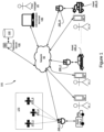
- Figure 1 shows a high-level block diagram of a telematics system 101.
- the telematics system 101 includes a telematics server 130, (N) telematics devices shown as telematics device 200_1, telematics device 200_2...through telematics device 200_N ("telematics device 200"), a network 50, administration terminal 140, and operator terminals 150_1, 150_2...through 150_N ("the operator terminals 150").
- Figure 1 also shows a plurality of (N) assets named as asset 100_1, asset 100_2...asset 100_N (“asset 100") coupled to the telematics device 200_1, telematics device 200_2...telematics device 200_N, respectively.
- Figure 1 shows a plurality of satellites 170_1, 170_2 and 170_3 (“the satellites 170") in communication with the telematics devices 200 for facilitating navigation.
- the assets 100 shown are in the form of vehicles.
- the asset 100_1 is shown as a truck, which may be part of a fleet that delivers goods or provides services.
- the asset 100_2 is shown as a passenger car that typically runs on an internal combustion engine (ICE).
- the asset 100_3 is shown as an electric vehicle (EV).
- Other types of vehicles, which are not shown, are also contemplated in the various embodiments of the present disclosure, including but not limited to, farming vehicles, construction vehicles, military vehicles, and the like.
- the telematics devices 200 are electronic devices which are coupled to assets 100 and configured to capture asset data from the assets 100.
- the telematics device 200_1 is coupled to the asset 100_1.
- the telematics device 200_2 is coupled to the asset 100_2 and the telematics device 200_3 is coupled to the asset 100_3.
- the components of a telematics device 200 are explained in further detail with reference to Figure 2 .
- the network 50 may be a single network or a combination of networks such as a data cellular network, the Internet, and other network technologies.
- the network 50 may provide connectivity between the telematics devices 200 and the telematics server 130, between the administration terminal 140 and the telematics server 130, and between the operator terminals 150 and the telematics server 130.
- the telematics server 130 is an electronic device executing machine-executable programming instructions which enable the telematics server 130 to store and analyze telematics data.
- the telematics server 130 may be a single computer system or a cluster of computers.
- the telematics server 130 may be running an operating system such as Linux, Windows, Unix, or any other equivalent operating system.
- the telematics server 130 may be a software component hosted on a cloud service, such as Amazon Web Service (AWS).
- AWS Amazon Web Service
- the telematics server 130 is connected to the network 50 and may receive telematics data from the telematics devices 200.
- the telematics server 130 may have a plurality of software modules for performing data analysis and analytics on the telematics data to obtain useful asset information about the assets 100.
- the telematics server 130 may be coupled to a telematics database 132 for storing telematics data and/or the results of the analytics which are related to the assets 100.
- the asset information stored may include operator information about the operators 10 corresponding to the assets.
- the telematics server 130 may communicate the asset data and/or the operator information pertaining to an asset 100 to one or more of: the administration terminal 140, and the operator terminal 150.
- the satellites 170 may be part of a global navigation satellite system (GNSS) and may provide location information to the telematics devices 200.
- the location information may be processed by a location module on the telematics device 200 to provide location data indicating the location of the telematics device 200 (and hence the location of the asset 100 coupled thereto).
- a telematics device 200 that can periodically report an asset's location is often termed an "asset tracking device”.
- the administration terminal 140 is an electronic device, which may be used to connect to the telematics server 130 to retrieve data and analytics related to one or more assets 100 or to issue commands to one or more telematics device 200 via the telematics server 130.
- the administration terminal 140 is shown as a laptop computer, but may also be a desktop computer, a tablet (not shown), or a smartphone.
- the administration terminal 140 may run a web browser or a custom application which allows retrieving data and analytics, pertaining to one or more assets 100, from the telematics server 130 via a web interface of the telematics server 130.
- the administration terminal 140 may also be used to issue commands to one or more telematics device 200 via the telematics server 130.
- a fleet manager 20 may communicate with the telematics server 130 using the administration terminal 140.
- the administration terminal 140 allows the fleet manager 20 to set alerts and geofences for keeping track of the assets 100, receiving notifications of deliveries, and so on.
- the operator terminals 150 are electronic devices, such as smartphones or tablets.
- the operator terminals 150 are used by operators 10 (for example, vehicle drivers) of the assets 100 to both track and configure the usage of the assets 100.
- the operator 10_1 has the operator terminal 150_1
- the operator 10_2 has the operator terminal 150_2
- the operator 10_N has the operator terminal 150_N.
- each of the operators 10 may operate any of the assets 100.
- Figure 1 shows that the operator 10_1 is associated with the asset 100_1, the operator 10_2 is associated with the asset 100_2, and the operator 10_N is associated with the asset 100_N.
- any operator 10 may operate any asset 100 within a particular group of assets, such as a fleet.
- the operator terminals 150 are in communication with the telematics server 130 over the network 50.
- the operator terminals 150 may run at least one asset configuration application.
- the asset configuration application may be used by an operator 10 to inform the telematics server 130 that the asset 100 is being currently operated by the operator 10.
- the operator 10_2 may use an asset configuration application on the operator terminal 150_2 to indicate that the operator 10_2 is currently using the asset 100_2.
- the telematics server 130 updates the telematics database 132 to indicate that the asset 100_2 is currently associated with the operator 10_2.
- the asset configuration application may be used to report information related to the operation duration of the vehicle, the number of stops made by the operator during their working shift, and so on. Furthermore, the asset configuration application may allow the operator to configure the telematics device 200 coupled to the asset 100 that the operator 10 is operating.
- a telematics device 200 is coupled to an asset 100 to capture asset data.
- the asset data may be combined with location data obtained by the telematics device 200 from a location module in communication with the satellites 170 and/or sensor data gathered from sensors in the telematics device 200 or another device coupled to the telematics device 200.
- the combined asset data, location data, and sensor data may be termed "telematics data.”
- the telematics device 200 sends the telematics data, to the telematics server 130 over the network 50.
- the telematics server 130 may process, aggregate, and analyze the telematics data to generate asset information pertaining to the assets 100 or to a fleet of assets.
- the telematics server 130 may store the telematics data and/or the generated asset information in the telematics database 132.
- the administration terminal 140 may connect to the telematics server 130, over the network 50, to access the generated asset information. Alternatively, the telematics server 130 may push the generated asset information to the administration terminal 140.
- the operators 10, using their operator terminals 150 may indicate to the telematics server 130 which assets 100 they are associated with.
- the telematics server 130 updates the telematics database 132 accordingly to associate the operator 10 with the asset 100.
- the telematics server 130 may provide additional analytics related to the operators 10 including work time, location, and operating parameters. For example, for vehicle assets, the telematics data may include turning, speeding, and braking information.
- the telematics server 130 can correlate the telematics data to the vehicle's driver by querying the asset database 310.
- a fleet manager 20 may use the administration terminal 140 to set alerts for certain activities pertaining to the assets 100. When criteria for an alert is met, the telematics server 130 sends a message to the administration terminal 140 to notify a fleet manager 20, and may optionally send alerts to the operator terminal 150 to notify an operator 10 of the alert. For example, a vehicle driver operating the vehicle outside of a service area or hours of service may receive an alert on their operator terminal 150.
- a fleet manager 20 may also use the administration terminal 140 to configure a telematics device 200 by issuing commands thereto via the telematics server 130. Alerts may also be sent to the telematics device 200 to generate an alert to the driver such as a beep, a displayed message, or an audio message.
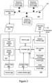
- Figure 2 depicts an asset 100 and a telematics device 200 coupled thereto. Selected relevant components of each of the asset 100 and the telematics device 200 are shown.
- the asset 100 may have a plurality of electronic control units (ECUs).
- An ECU is an electronic module which interfaces with one or more sensors for gathering information from the asset 100.
- an engine coolant temperature (ECT) ECU may contain a temperature sensor and a controller for converting the measured temperature into digital data representative of the oil temperature.
- ECT engine coolant temperature
- a battery voltage ECU may contain a voltage sensor for measuring the voltage at the positive battery terminal and a controller for converting the measured voltage into digital data representative of the battery voltage.
- a vehicle may, for example, have around seventy ECUs. For simplicity, only a few of the ECUs 110 are depicted in Figure 2 .
- the asset 100 has three ECUs shown as the ECU 110A, the ECU 110B, and the ECU 110C ("the ECUs 110").
- the ECU 110A, the ECU 110B, and the ECU 110C are shown to be interconnected via an asset communications bus.
- An asset communications bus is a Controller Area Network (CAN) bus.
- CAN Controller Area Network
- the ECUs 110 are interconnected using the CAN bus 104.
- the ECUs 110 send and receive information to one another in CAN data frames by placing the information on the CAN bus 104.
- an ECU 110 places information on the CAN bus 104, other ECUs 110 receive the information and may or may not consume or use that information.
- ECUs 110 in trucks and heavy vehicles use the Society of Automotive Engineering (SAE) J1939 protocol to exchange information over a CAN bus 104.
- SAE J1939 protocol Most passenger vehicles use the SAE J1979 protocol, which is commonly known as On-Board Diagnostic (OBD) protocol to exchange information between ECUs 110 on their CAN bus 104.
- OBD On-Board Diagnostic
- ECUs use a CANOpen protocol to exchange information over a CAN bus 104.
- An asset 100 may allow access to information exchanged over the CAN bus 104 via an interface port 102.
- the interface port 102 is most likely an OBD-II port.
- Data accessible through the interface port 102 is termed the asset data 112.
- the interface port 102 includes a power interface for providing electric power to a telematics device 200 connected thereto.
- the telematics device 200 includes a controller 230 coupled to a memory 240, an interface layer 210 and a network interface 220.
- the telematics device 200 also includes one or more sensors 204 and a location module 206 coupled to the interface layer 210.
- the telematics device 200 may also contain some optional components, shown in dashed lines in Figure 2 .
- the telematics device 200 may contain one or more of: a near-field communications (NFC) module such as NFC module 260, a short-range wireless communications module 270, and a wired communications module such as a serial communications module 280.
- NFC near-field communications
- the telematics device 200 may have a dedicated power source or a battery.
- the telematics device 200 may receive power directly from the asset 100, via the interface port 102.
- the telematics device 200 shown is an example. Some of the components shown in solid lines may also be optional and may be implemented in separate modules. For example, some telematics devices (not shown) may not have a location module 206 and may rely on an external location module for obtaining the location data 207. Some telematics devices may not have any sensors 204 and may rely on external sensors for obtaining sensor data 205.
- the controller 230 may include one or any combination of a processor, microprocessor, microcontroller (MCU), central processing unit (CPU), processing core, state machine, logic gate array, application-specific integrated circuit (ASIC), field-programmable gate array (FPGA), or similar, capable of executing, whether by software, hardware, firmware, or a combination of such, the actions performed by the controller 230 as described herein.
- the controller 230 may have an internal memory for storing machine-executable programming instructions to conduct the methods described herein.
- the memory 240 may include read-only-memory (ROM), random access memory (RAM), flash memory, magnetic storage, optical storage, and similar, or any combination thereof, for storing machine-executable programming instructions and data to support the functionality described herein.
- the memory 240 is coupled to the controller 230 thus enabling the controller 230 to execute the machine-executable programming instructions stored in the memory 240 and to access the data stored therein.
- the memory 240 may contain machine-executable programming instructions, which when executed by the controller 230, configures the telematics device 200 for receiving asset data 112 from the asset 100 via the asset interface 202, and for receiving sensor data 205 from the sensors 204 and/or location data 207 from the location module 206 via the sensor interface 208.
- the memory 240 may also contain machine-executable programming instructions for combining asset data 112, sensor data 205 and location data 207 into telematics data 212. Additionally, the memory 240 may further contain instructions which, when executed by the controller 230, configures the telematics device 200 to transmit the telematics data 212 via the network interface 220 to a telematics server 130 over a network 50. In some embodiments, the memory 240 only stores data, and the machine-executable programming instructions for conducting the aforementioned tasks are stored in an internal memory of the controller 230.
- the location module 206 may be a global positioning system (GPS) transceiver or another type of location determination peripheral that may use, for example, wireless network information for location determination.
- the location module 206 is coupled to the controller 230 and provides location data 207 thereto.
- the location data 207 may be in the form of a latitude and longitude, for example.
- the sensors 204 may be one or more of: a temperature sensor, a pressure sensor, an optical sensor, a motion sensor such as an accelerometer, a gyroscope, or any other suitable sensor indicating a condition pertaining to the asset 100 to which the telematics device 200 is coupled.
- the sensors provide sensor data 205 to the controller 230 via the sensor interface 208.
- the interface layer 210 may include a sensor interface 208 and an asset interface 202.
- the sensor interface 208 is configured for receiving the sensor data 205 from the sensors 204.
- the sensor interface 208 interfaces with the sensors 204 and receives the sensor data 205 therefrom.
- the asset interface 202 receives asset data 112 from the asset 100.
- the asset interface 202 is coupled to the interface port 102 of the asset 100.
- the asset data 112, received at the telematics device 200, from the asset 100 may be in the form of data messages, such as CAN data frames.
- the asset data 112 may describe one or more of any of: a property, a state, and an operating condition of the asset 100.
- the data may describe the speed at which the vehicle is traveling, a state of the vehicle (off, idle, or running), or an engine operating condition (e.g., engine oil temperature, engine revolutions-per-minutes (RPM), or a battery voltage).
- the asset interface 202 may also receive power from the asset 100 via the interface port 102.
- the interface layer 210 is coupled to the controller 230 and provides both the asset data 112 and the sensor data 205 to the controller 230.
- the network interface 220 may include a cellular modem, such as an LTE-M modem, CAT-M modem, other cellular modem, Wi-Fi modem, or any other communication device configured for communication via the network 50 with which to communicate with the telematics server 130.
- the network interface 220 may be used to transmit telematics data 212 obtained from the asset 100 to the telematics server 130 for a telematics service or other purposes.
- the network interface 220 may also be used to receive instructions from the telematics server 130 for configuring the telematics device 200 in a certain mode and/or requesting a particular type of the asset data 112 from the asset 100.
- the NFC module 260 may be an NFC reader which can read information stored on an NFC tag.
- the NFC module 260 may be used to confirm the identity of the operator 10 by having the operator 10 tap an NFC tag onto the telematics device 200 such that the NFC tag is read by the NFC module 260.
- the information read from the NFC tag may be included in the telematics data 212 sent by the telematics device 200 to the telematics server 130.
- the short-range wireless communications module 270 is a component intended for providing short-range wireless communication capability to the telematics device 200.
- the short-range wireless communications module 270 may be a BluetoothTM. wireless fidelity (Wi-Fi), ZigbeeTM, or any other short-range wireless communications module.
- Wi-Fi wireless fidelity
- ZigbeeTM ZigbeeTM
- the short-range wireless communications module 270 allows other devices to communicate with the telematics device 200 over a short-range wireless network.
- the serial communications module 280 is an example of a wired communications module.
- the serial communications module 280 is an electronic peripheral for providing serial wired communications to the telematics device 200.
- the serial communications module 280 may include a universal asynchronous receiver transmitter (UART) providing serial communications per the RS-232 protocol.
- the serial communications module 280 may be a serial peripheral interface (SPI) bus, or an inter-integrated circuit (I2C) bus.
- the serial communications module 280 may be a universal serial bus (USB) transceiver.
- an ECU 110 such as the ECU 110A, the ECU 110B, or the ECU 110C communicates asset data over the CAN bus 104.
- the asset data exchanged, between the ECUs 110, over the CAN bus 104 are accessible via the interface port 102 and may be retrieved as the asset data 112 by the telematics device 200.
- the controller 230 of the telematics device 200 receives the asset data 112 via the asset interface 202.
- the controller 230 may also receive sensor data 205 from the sensors 204 over the sensor interface 208.
- the controller 230 may receive location data 207 from the location module 206.
- the controller 230 combines the asset data 112 with the sensor data 205 and the location data 207 to obtain the telematics data 212.
- the controller 230 transmits the telematics data 212 to the telematics server 130 over the network 50 via the network interface 220.
- an operator 10 may tap an NFC tag to the NFC module 260 to identify themself as the operator 10 of the asset 100.
- an external peripheral such as a GPS receiver, may connect with the telematics device 200 via the short-range wireless communications module 270 or the serial communications module 280 for providing location information thereto.
- the telematics device 200 may receive, via the network interface 220, commands from the telematics server 130.
- the received commands instruct the telematics device 200 to be configured in a particular way.
- the received commands may configure the way in which the telematics device gathers asset data 112 from the asset 100 as will be described in further detail below.
- the telematics data 212 which is composed of asset data 112 gathered from the asset 100 combined with the sensor data 205 and the location data 207 may be used to derive useful data and analytics, by the telematics server 130. However, there are times when additional data, which is not provided by the asset 100, the sensors 204 or the location module 206 may be needed.
- the telematics device 200 may have a limited number of sensors 204 such as accelerometers or gyroscopes providing limited information about the motion of the asset 100 on which the telematics device 200 is deployed.
- the location module 206 may provide location and direction information. However, in some cases, more information may be needed to derive useful data and analytics pertaining to the asset 100.
- One example of information that is not typically provided by the telematics device 200 is video capture data.
- Another example of information that is not typically provided by the telematics device 200 is any proprietary signaling provided by devices which does not follow any of the standard protocols (OBD-II, J1939 or CANOpen).
- Some equipment may not have a CAN bus and may provide proprietary digital and/or analog signals. Examples of such devices include industrial equipment, winter maintenance equipment such as salt spreaders, farming equipment, and the like.
- the telematics device 200 may not have an NFC module 260 or a short-range wireless communications module 270 thus limiting its connectivity capabilities.
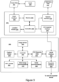
- the telematics device 200 may be modified to allow an input/output expander device ("I/O expander") to connect thereto, as shown in Figure 3.
- Figure 3 shows a telematics device 201 coupled to an asset 100.
- An I/O expander 300 is coupled to the telematics device 201.
- the asset 100 is similar to the asset 100 of Figure 2 and therefore the internal components thereof are not shown in Figure 3 for simplicity.
- the telematics device 201 has a somewhat similar configuration as the telematics device 200 of Figure 2 , but some of the optional components have been removed. Furthermore, the telematics device 201 adds an I/O expander interface 250 for interfacing with the I/O expander 300.
- the I/O expander interface 250 is coupled to the controller 230 and may be configured for exchanging I/O expander data 312 with the I/O expander 300.
- the I/O expander 300 of Figure 3 is an example I/O expander which is designed to provide additional connectivity options to a telematics device 200, which has more limited features than the one shown in Figure 2 .
- the telematics device 201 shown in Figure 3 does not have an NFC module, a short-range wireless communications module, or a serial communications module. Instead, the telematics device 201 has an I/O expander interface 250.
- the I/O expander 300 may be an input device configured to capture additional data such as video frames, audio frames, or proprietary signals and provide that data to the telematics device 201.
- the I/O expander 300 may be configured as an output device and may include a display for displaying information and/or an audio output device for broadcasting messages pertaining to the asset 100.
- An I/O expander 300 which connects with the telematics device 201, varies in complexity depending on the purpose thereof.
- Figure 3 shows an I/O expander 300 containing several components which may or may not all be present in other I/O expanders.
- the I/O expander 300 includes a controller 330, an NFC module 260, an output device 340, a short-range communications module 370, an image sensor 390, a serial communications module 380, an uplink interface 350 and a downlink interface 520.
- the controller 330 may be similar to the controller 230 of Figure 3 .
- the controller 330 is a microcontroller with versatile I/O capabilities.
- the controller 330 may be a microcontroller which has a plurality of I/O ports such as general-purpose inputs and outputs (GPIOs), serial ports, analog inputs, and the like.
- the controller 330 may have built-in persistent memory such as flash memory on which machine-executable programming instructions for conducting the functionality of the I/O expander 300 may be stored.
- the controller 330 may be coupled to a persistent memory module (not shown) that contains the machine-executable programming instructions for conducting the functionality of the I/O expander 300.
- the controller 330 may also have built-in volatile memory, such as random-access memory (RAM) for storing data.
- RAM random-access memory
- the I/O expander 300 may be connected to an external volatile memory for storing data.
- the output device 340 receives data from the controller 330 and performs an output function.
- the output device 340 may include a display for displaying information received from the controller 330.
- the output device 340 may include a speech synthesizer and a speaker for displaying audible information received from the controller 330.
- the output device 340 may be an output interface to a hardware device.
- the output device 340 may be a motor controller that interfaces to an electric motor.
- the NFC module 360, short-range communications module 370, and the serial communications module 380 are similar to the NFC module 260, short-range wireless communications module 270, and the serial communications module 280 described above with reference to Figure 2 .
- the image sensor 390 may be a digital still camera or a digital video camera capable of capturing images.
- the image sensor 390 may be a road-facing dashboard camera for monitoring the road ahead.
- the image sensor 390 may be a driver-facing dashboard camera for identifying the operator 10 and/or their condition.
- the uplink interface 350 is an electronic peripheral interface coupled to the controller 330 and is used to provide data exchange and/or power capabilities to the I/O expander 300.
- the uplink interface 350 allows the I/O expander 300 to transmit and receive I/O expander data.
- the uplink interface 350 is configured to use the same protocol and signaling as the I/O expander interface 250 of the telematics device 201. Accordingly, the I/O expander 300 may exchange the I/O expander data with the telematics device 201.
- the uplink interface 350 may also include power pins connected to corresponding power pins in the I/O expander interface 250, thus allowing the I/O expander 300 to be powered via the telematics device 201.
- the I/O expander 300 may have its own power source instead of or in addition to the power provided by the telematics device 201 via the uplink interface 350.
- the downlink interface 520 is an electronic peripheral interface coupled to the uplink interface 350.
- the downlink interface 520 is configured to interface with the uplink interface 350 of another I/O expander 300 (as will be described below). Allowing the uplink interface 350 to connect to the downlink interface 320 of another I/O expander allows the daisy chaining of I/O expanders.
- a telematics device is shown as a separate entity connected with a corresponding asset.
- the telematics device may have its components integrated into the asset 100 at the time of manufacture of the asset 100. This may be the case when the asset 100 is a connected car having an asset network interface.
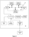
- an asset 400 with the components of a telematics device integrated therein, in accordance with embodiments of the present disclosure.
- the asset 400 is similar to the asset 100 but, being a connected asset such as a connected car, it has an asset network interface 122.
- the controller 230 is directly connected to the asset communications bus, which is a CAN bus 104 and may directly obtain the asset data 112 therefrom.
- the sensors 204 and the location module 206 are also integrated into the asset 100 and provide the sensor data 205 and the location data 207 to the controller 230 as described above.
- the asset network interface 122 belongs to the asset 400 and may be used by the asset 400 to communicate with an original equipment manufacturer (OEM) server, to a roadside assistance server, or for other purposes.
- the controller 230 may utilize the asset network interface 122 for the transmission of telematics data 212 provided by the controller 230.
- OEM original equipment manufacturer
- the asset has an I/O expander interface 250 coupled to the controller 230 so that an I/O expander 300 may be connected to the asset 400 therethrough.
- the asset 400 may have an interface port 102 for connecting other devices other than a telematics device 200, such as a diagnostic tool including, but not limited to, an OBD-II reader device.
- the telematics server 130 maintains a plurality of rules that trigger actions or alerts based on the received telematics data 212.
- the rules may be configured by a fleet manager 20 for example, using an administration terminal 140.
- the telematics server 130 may, in response to receiving the telematics data 212, send an alert condition to a telematics device to trigger an action thereon. Additionally, the telematics server 130 may send the alert condition to the administration terminal 140.
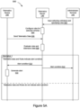
- Figure 5A is a message sequence diagram depicting a method 500 of generating an alert condition based on rules and telematics data 212, in accordance with embodiments of the present disclosure.
- the method 500 starts at step 502.
- a fleet manager 20 may use an administration terminal 140 to connect to the telematics server 130 and configure some rules for a vehicle or a group of vehicles. Details of the user interface and the options for configuring the rules will be described below.
- the administration terminal 140 may connect to the telematics server 130 by means of a web browser or a mobile application, for example.
- the telematics server 130 configures a plurality of rules for one or more vehicles selected in the input received from the administration terminal 140 in step 502.
- the telematics server 130 may store the rules in the telematics database 132 or internally within the telematics server 130.
- the telematics device 200 sends telematics data 212 to the telematics server 130.
- the telematics server 130 receives the telematics data 212 and may store the telematics data 212 in the telematics database 132 or in an internal storage.
- the telematics server 130 evaluates the telematics data 212 in light of the rules.
- the evaluation of telematics data 212 in light of the rules may generate an alert condition.
- the telematics data 212 may indicate excessive speed, harsh braking, hard cornering, or a mechanical failure with the vehicle to which the telematics device 200 is coupled.
- the telematics server 130 may determine that the location of the telematics device 200 is within a geographic zone and that one of the rules stipulates that an alert must be generated. If the evaluation of the telematics data 212 and the rules indicate an alert condition, then at step 510, the telematics server 130 sends a message indicating an alert condition to the telematics device 200.
- An alert sent to the telematics device 200 may be used to trigger an alert indication on the telematics device 200.
- An alert indication on the telematics device 200 may be a beep, a flashing of an LED (light emitting diode), a message displayed on a display such as an LCD (liquid crystal display), or a voice message played over an audio device.
- the telematics server 130 in response to evaluating the telematics data 212 in light of the rules, may also send a message indicating an alert condition to the administrator terminal 140 as shown in step 512.
- a fleet manager 20 may be interested in receiving an alert when a vehicle in the fleet is driving over the speed limit.
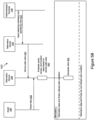
- the telematics device 200 may evaluate the asset data 112, sensor data 205, and location data 207 and determine whether an alert condition has been satisfied. This is described with reference to Figure 5B .
- Step 522 is similar to step 502 of Figure 5A .
- An input on an administration terminal 140 specifies telematics device-side rules for one or more vehicles.
- the device-side rules are rules which the telematics server 130 is to relay to the telematics device 200 corresponding to the selected vehicles specified in the input provided at the administration terminal 140.
- the telematics server 130 sends the device-side rules to the telematics device 200.
- the telematics device 200 receives the device-side rules.
- the asset 100 sends asset data 112 to the telematics device 200.
- the telematics device 200 receives the asset data 112.
- the telematics device 200 evaluates the asset data 112, and one of the sensor data 205 and the location data 207 based on the device-side rules. Some rules may be based only on the asset data 112. For example, a trouble code provided in the asset data 112 and indicating failure of an engine component may be sufficient to raise an alert condition. In other cases, the location data 207 may give an indication of the vehicle being in a particular zone that should trigger an alert condition. In further cases, the sensor data 205 may provide an indication of harsh braking or cornering based on accelerometer readings. Accordingly, the telematics device 200 may determine an alert condition based on some or all of the components of the telematics data 212.
- the telematics device 200 If the telematics data 212 indicate an alert condition, then at step 532, the telematics device 200 generates an alert.
- Figures 6 through 9 depict user interfaces which may be displayed on the display of the administration terminal 140 for configuring the rules on the telematics server 13.
- Figure 6 depicts a rules category selection user interface 600 which allows selecting a vehicle or a group of vehicles, and selecting a category of rules to configure for the selected vehicle or group of vehicles.
- the rules category selection user interface comprises a vehicle or group selection user interface control 602, a rules category selection user interface control 630, and a flow user interface control 680.
- the vehicle or group selection user interface control 602 includes a vehicle selector 610 and a group selector 620.
- the group selector 620 is showing three groups given generic names such as "Group 1" labeled as the user interface element 622, "Group 2" labeled as the user interface element 624, and "Group 3" labeled as the user interface element 626.
- the rules category selection user interface control 630 includes user interface elements for selecting rule categories.
- the rules category selection user interface control 630 comprises a safety user interface element 632, a productivity user interface element 634, a fleet optimization user interface element 636, a compliance user interface element 638, a sustainability user interface element 640, and a material management user interface element 642.
- a user interface element may be selected by touching or clicking. A selected user interface element is highlighted.
- the flow user interface control 680 controls the flow of the rule configuration process.
- the flow user interface control 680 comprises a next user interface element 684 and a cancel user interface element 682. Activating the cancel user interface element 682 abandons the rules configuration process. Activating the next user interface element 684 proceeds with the next step of the rule configuration process.
- the user selects either a vehicle or a group of vehicles.
- the vehicle selector 610 is activated and a list of vehicles are displayed (not shown).
- the group selector 620 is activated and a group is selected from the list of group user interface elements.
- the group named "Group 2" corresponding to the group user interface element 624 is being selected.
- a rules category a user interface element from the rules category selection user interface control 630 is selected.
- the safety user interface element 632 is selected.
- the next user interface element 684 may be activated.
- the telematics server 130 determines the selected rule category and displays a corresponding user interface for selecting a rule from the selected rule category.
- the safety category is selected as depicted by highlighting the safety user interface element 632. Accordingly, in response to activating the next user interface element 684, a safety rule selection user interface 700 is displayed, as shown in Figure 7 .
- Figure 7 depicts a safety rule selection user interface 700 for selecting a safety rule to configure for a vehicle or group of vehicles.
- the safety rule selection user interface 700 comprises the vehicle selector 610 and group selector 620 described above, a safety rule selection user interface control 730, and a flow user interface control 780.
- the vehicle or group selection user interface control 602 shows the selections made in the previous user interface, i.e., that "Group 2" has been selected.
- the safety rule selection user interface control 730 comprises a plurality of user interface elements each corresponding to a safety rule.
- the safety rule selection user interface control 730 includes a harsh braking user interface element 732, a hard acceleration user interface element 734, a harsh cornering user interface element 736, a speeding user interface element 738, a seat belt user interface element 740, an after hours usage user interface element 742, a backing up when leaving user interface element 744, and a possible collision user interface element 746.
- the flow user interface control 780 controls the flow of the rule configuration process.
- the flow user interface control 780 comprises a next user interface element 784 and a previous user interface element 782. Activating the user interface element 682 abandons a safety rule selection user interface 700 and displays the rules category selection user interface 600. Activating the next user interface element 684 proceeds with the next step of the rule configuration process.
- the user activates a safety rule by activating the corresponding safety rule user interface element.
- the speeding user interface element 738 has been activated and is highlighted indicating that the corresponding speeding rule has been selected for configuration.
- the speeding rule configuration user interface 800 is displayed as shown in Figure 8 .
- Figure 8 depicts a speeding rule configuration user interface 800 for editing the speeding rule.
- the speeding rule configuration user interface 800 includes a vehicle or group selection user interface control 602, and a speeding rule edit user interface control 810.
- the speeding rule edit user interface control 810 is configured to allow the rule conditions to be configured. Accordingly, a conditions configuration user interface 820 is shown.
- the speeding rule configuration user interface 800 also comprises a flow user interface control 880.
- the vehicle or group selection user interface control 602 shows the selections made in the previous user interface, i.e., that "Group 2" has been selected.
- the speeding rule edit user interface control 810 allows selecting a category of parameters to edit, such as the name, the conditions, and the notifications. Accordingly, the speeding rule edit user interface control contains a name user interface element 802, a conditions user interface element 804, and a notifications user interface element 806.
- the name user interface element 802 can be activated to display a user interface control (not shown) for entering a name for the speeding rule.
- the conditions user interface element 804 can be activated to display a conditions configuration user interface 820 as shown in Figure 8 and the notifications user interface element 806 can be activated to display a notifications configuration user interface 902 as will be described below with reference to Figure 9 .
- the conditions user interface element 804 is selected and accordingly the conditions configuration user interface 820 is shown.
- the conditions configuration user interface 820 consists of condition user interface control 812 and a conditions text field 830.
- the condition user interface control 812 has a plurality of condition user interface elements for specifying a condition based on speed, speed limit, distance, and duration.
- the condition user interface elements are used to form a condition for the rule in the conditions text field 830.
- the speed user interface element 822 when activated specifies a rule that is based on the absolute speed of the vehicle. For example, the speed user interface element may specify a condition that is satisfied when the vehicle speed is at 110 km/h regardless of the speed limit of the road being traveled on.
- the speed limit user interface element 824 when activated, specifies a rule that is based on the current speed limit of the street that the vehicle is currently traveling on. For example, as shown in the conditions text field, part of the rule specifies a condition that the vehicle's current speed is 10 Km/h higher than the current speed limit.
- the distance user interface element 826 when activated, specifies the distance that the vehicle has to travel for while meeting the speeding condition before an alert is generated.
- the distance user interface element 826 is used to modify an existing rule that uses either the speed or the speed limit.
- the duration user interface element 828 when activated, specifies the time duration that the vehicle has to travel while meeting the speeding condition before an alert is generated.
- the duration user interface element 828 is used to modify an existing rule that uses either the speed or the speed limit.
- the conditions text field 830 specifies the conditions that need to be met to trigger the current speeding rule.
- the currently depicted speeding conditions text field shows a rule that is triggered by the vehicle traveling over the speed limit by 10 Km/h for a duration that is more than 20 seconds.
- a notification can be triggered.
- a notifications user interface element is activated.
- a notification configuration user interface element is displayed. For example, in the depicted embodiment, activating the notifications user interface element 806 causes the conditions configuration user interface 820 to be replaced with the notifications configuration user interface 902, as shown in Figure 9 .
- the flow user interface control 880 controls the flow of the rule configuration process.
- the flow user interface control 880 comprises a save user interface element 884 and a previous user interface element 882. Activating the previous user interface element 882 cancels the speeding rule configuration and displays the safety rules selection user interface 700. Activating the save user interface element 884 saves the current rule configuration.
- Figure 9 shows the speeding rule configuration user interface 800 described above, with the exception that the conditions user interface 820 has been replaced with the notifications configuration user interface 902.
- the notifications configuration user interface 902 consists of a notification type user interface control 905, and a notification text field 940.
- the notification type user interface control 905 includes an email notification user interface control 910, a Short Messaging Service (SMS) notification user interface control 920, and a driver feedback user interface control 930.
- the email notification user interface control 910 when activated, allows specifying an email address to which an email is sent if the condition for the rule specified in the conditions text field 830 is satisfied.
- the SMS notification user interface control 920 when activated, allows specifying a mobile telephone number to which an SMS message is sent if the condition for the rule specified in the conditions text field 830 is satisfied.
- the driver feedback user interface control 930 allows specifying a notification local to the telematics device.
- the driver feedback may be in the form of a beep, a text message displayed on a display, or a voice message played by an audio device containing a speaker. Accordingly, activating the driver feedback user interface control 930 displays a plurality of user interface elements namely the beep user interface element 932, the text message user interface element 934, and the voice message user interface element 936.
- the notification text field 940 contains the notifications message which may be sent over email, SMS, or used in the driver feedback.
- the voice message user interface element 936 is highlighted indicating that a voice message is being configured.
- the notification text field 940 contains the alert message "You are driving over the speed limit. Please reduce speed to 100 Km/h", which is to be played over an audio device coupled to the telematics device, as will be described below.
- a fleet manager 20 using an administration terminal may configure a voice message to be played whenever a vehicle is driven 10 Km/h over the speed limit for 20 seconds, for example.
- the vehicle or group are selected using the vehicle or group selection user interface control 602.
- the speeding rule is under the safety user interface element 632 in the rules category selection user interface control 630.
- the safety rule selection user interface 700 is displayed.
- the speeding user interface element 738 is selected from the safety rule selection user interface control 730.
- the speeding rule configuration user interface 800 is displayed.
- the speeding rule interface 800 has the conditions user interface element 804 selected and therefore the conditions configuration user interface 820 displayed.
- the conditions of a speeding rule are entered in the conditions text field 830.
- Different elements may be entered using the conditions user interface controls such as the speed user interface element 822, the speed limit user interface element 824, the distance user interface element 826, and the duration user interface element 828.
- the current speed of the vehicle is entered in the conditions text field 830 by clicking the speed user interface element 822, which is in the form of a button.
- the user may type some text such as "compared to" or it may be entered automatically after the current speed is entered.
- the speed limit is added to the conditions text field 830.
- the offset 10 Km/h over the speed limit may be entered manually.
- the duration user interface element 828 may be activated (i.e., touched or clicked).
- the notifications user interface element 806 may be activated.
- the notifications configuration user interface 902 is displayed.
- a number of options are displayed such as a beep user interface element 932, a text message user interface element 934, and a voice message user interface element 936.
- the voice message user interface element 936 is selected.
- a notification text field 940 is displayed in which a text message may be entered.
- FIG 10 depicts a telematics device 201 coupled to an I/O expander in the form of an audio output expander 1000, in accordance with embodiments of the present disclosure.
- the telematics device 201 has been described above with reference to Figure 3 .
- the audio output device 1000 has a controller 1030, an uplink interface 1050, a speech synthesizer 1040, a speaker 1060, and a volume control module 1010.
- the controller 1030 and the uplink interface 1050 are similar to the controller 330 and the uplink interface 350 of Figure 3 , respectively.
- the speech synthesizer 1040 is an electronic hardware device that converts text to speech thus generating an audible message from a text message provided thereto.
- the speech synthesizer 1040 is implemented in firmware that is executed by the controller 1030 from an internal memory thereof.
- the speech synthesizer 1040 may include an amplifier for amplifying the audible message generated by the speech synthesizer.
- the speaker 1060 is an audio loudspeaker coupled to the speech synthesizer 1040 and configured to play out audio messages generated by the speech synthesizer 1040.
- the volume control module 1010 is a hardware module that provides a signal indicative of the desired volume.
- the volume control module 1010 may include an attenuator or a potentiometer coupled to a rotary or slider control for providing a variable analog signal to the controller 1030.
- the controller 1030 may comprise an analog to digital converter (ADC) for converting the analog signal into a digital value.
- ADC analog to digital converter
- the telematics device 201 may determine that an alert message 1020 needs to be played over the audio output expander 1000.
- the alert message 1020 may need to be played in response to triggering a rule wherein the notification has been configured to generate a voice message as discussed above.
- the controller 230 of the telematics device 201 may send the alert message 1020 over the I/O expander interface 250 to the audio output expander 1000.
- the controller 1030 receives the alert message 1020 and sends it to the speech synthesizer 1040.
- the alert message 1020 may be in the form of text, similar to the text message in the notification text field 940 of Figure 9 .
- the speech synthesizer 1040 generates an audible alert message 1062 and plays it on the speaker 1060 coupled thereto.
- the audible alert message 1062 may or may not be heard by the operator 10 of the vehicle depending on the ambient noise. Accordingly, the operator 10 may choose to increase the volume using the volume control module 1010 if the vehicle has loud engine noise or is being operated in a noisy environment such as a construction site. Adjusting the volume control module 1010 changes the analog signal provided to the controller 1030.
- the controller 1030 may use an ADC to convert the analog signal to a digital value indicating the desired volume.
- the controller 1030 may adjust the volume of the speech synthesizer 1040 based on the digital value that indicates the desired volume.
- the volume control module 1010 is directly coupled to the speech synthesizer 1040 and controls the audio output level (i.e., volume) thereof.
- an operator 10 wishing not to hear any audible alert messages 1062 may turn down the volume of the audio produced by the speaker 1060 by adjusting the volume control module 1010 to the lowest possible setting thereof.
- a fleet manager 20 may not appreciate the operator 10 disabling or lowering the volume of the audible alert messages as it may prevent the operator 10 from recognizing certain unacceptable practices and thus prevents them from correcting them.
- an audio output expander 1100 without a volume control module 1010 may be desirable in order to force an operator 10 to always hear the audible alert messages.
- removing the volume control module 1010 poses a problem regarding the volume or audio output level of the speaker 1060.
- An audio output level that is set too high may be irritating to the operator 10 and is unnecessary when the vehicle is being operated in a quiet environment. Conversely, an audio output level which is set too low may not be audible in a noisy environment. Accordingly, an audio output expander needs to employ automatic volume control (AVC) and adjust the audio output level (volume) based on ambient noise.
- AVC automatic volume control
- An audio output expander 1100 that employs automatic volume control is shown in Figure 11 .
- FIG 11 depicts a telematics device 201 and an audio output expander 1100 coupled thereto.
- the audio output expander 1100 has similar components to the audio output expander 1000 except that it features some audio components for automatic volume control.
- the telematics device 201 includes a microphone 1012 and an audio input module 1013 instead of the volume control module 1010.
- the microphone 1012 is used to capture ambient noise.
- the audio input module 1013 converts the signal provided by the microphone into a signal that may be processed by the controller 1030.
- the audio input module 1013 may comprise an analog to digital converter (ADC) and a digital signal processor (DSP). In operation the microphone 1012 captures ambient noise and provides an audio signal to the audio input module 1013.
- ADC analog to digital converter
- DSP digital signal processor
- the audio input module 1013 provides a digital signal indicative of the ambient noise to the controller 1030. Based on the digital signal indicative of the ambient noise, the controller 1030 may adjust the volume of the speech synthesizer 1040 to a higher level so that the audible messages output by the speaker 1060 are audible over the ambient noise. Conversely, when the ambient noise is low, the controller 1030 may adjust the audio output level of the speech synthesizer to a lower level so that the audible output message by the speaker 1060 is not too loud.
- the audio output expander 1100 of Figure 11 may address the issue of the ambient noise, it relies on having the microphone 1012 being on all the time and the controller 1030 constantly processing the audio captured by the microphone 1012. Having the microphone 1012 capturing audio at all times may raise some privacy concerns and also consumes electric power unnecessarily. Accordingly, the inventor has produced a scheme wherein the microphone 1012 and the automatic volume control mechanism are only enabled with each alert message 1020. This is explained further with reference to Figure 12 .
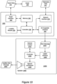
- Figure 12 depicts a telematics device 201 coupled to an audio output expander 1200.
- the audio output expander 1200 has a similar structure as the audio output expander 1100 but has a power control module 1032 coupled to the controller 1030, the microphone 1012, and the audio input module 1013.
- the power control module 1032 may power the microphone 1012 and the audio input module 1013 up or down based on control signals from the controller 1030.
- the power control module 1032 is shown as a separate component in dashed lines to indicate that the functionality thereof may be integrated into the controller 1030 in which case the power control module 1032 may not be present.
- the telematics device 201 determines that the audio output expander 1200 needs to generate an alert audio message. This may be due to an alert condition determined by the telematics device 201 or determined by the telematics server 130 and sent to the telematics device 201.
- the controller 1030 receives an alert message 1020 while the microphone 1012 and the audio input module 1013 are powered off.
- the controller 1030 sends control signals to the power control module 1032 instructing the power control module 1032 to power up the microphone 1012 and the audio input module 1013.
- the power control module 1032 reports back to the controller 1030 with a confirmation that the microphone 1012 and the audio input module 1013 are fully powered up.
- the controller 1030 invokes an automatic volume control procedure to detect the ambient noise and adjust the audio output level of the speech synthesizer 1040. Once the audio output level of the speech synthesizer is adjusted, the controller 1030 instructs the power control module 1032 to power off the microphone 1012 and the audio input module 1013. The power control module 10132 may report back or indicate to the controller 1030 that the microphone 1012 and the audio input module 1013 have been powered off. In response to determining that that microphone 1012 and the audio input module 1013 have been powered off, the controller sends the alert message 1020 to the speech synthesizer so that an audible alert message corresponding to the alert message 1020 may be played over the speaker 1060.
- the audible alert message generated by the audio output expander 1200 be generated in real-time or near real-time.
- the steps of powering up the microphone 1012, powering up the audio input module 1013, and invoking an automatic volume control procedure may delay the playback of the audible alert message generated by the speech synthesizer over the speaker 1060.
- the microphone 1012 and the audio input module 1013 are powered up and that the automatic volume control procedure is invoked in advance of the need to playback an audible alert message
- the telematics device 201 sends an AVC trigger message 1022 prior to sending the alert message 1020.
- the AVC trigger message 1022 indicates that an alert message 1020 may be forthcoming.
- the controller 1030 may instruct the power control module 1032 to power up the microphone 1012 and the audio input module 1013 as before.
- the controller 1030 invokes the automatic volume control procedure to determine the optimal audio output level of the speech synthesizer 1040.
- the controller 1030 adjusts the output level of the speech synthesizer 1040 with the optimal audio output level.
- the controller 1030 then instructs the power control module 1032 to power down the microphone 1012 and the audio input module 1013.
- the telematics device 201 may send an alert message 1020 to the audio output expander 1200.
- the controller 1030 In response to receiving the alert message 1020, the controller 1030 sends the alert message 1020 to the speech synthesizer 1040 for generating a corresponding audible alert message that is played back through the speaker 1060.
- the telematics device 201 may send the AVC trigger message 1022, but does not send the alert message 1020, as explained below.
- the telematics device 201 sends an AVC trigger message 1022 prior to sending the alert message 1020 to the audio output expander 1200.
- the AVC trigger message 1022 is thus generated based on a different condition than the alert message 1020.
- a first threshold may be defined for generating the AVC trigger message 1022
- a second threshold may be defined for generating the alert message 1020.
- the first threshold and second threshold may be vehicle parameters, distance traveled, or duration.
- the speeding rule shown has a condition of driving over the speed limit by 10 Km/h for a duration of 20 seconds.
- the first threshold may be driving at a speed which is only 5 Km/h over the speed limit.
- the telematics device 201 may send an AVC trigger message 1022 to the audio output expander 1200 as soon as the speed limit is exceeded by 10 Km/h.
- the audio output expander 1200 may have up to 20 seconds to enable the audio components used for detecting ambient noise for automatic volume control such as the microphone 1012 and the audio input module, and to invoke an automatic volume control procedure. If the vehicle speed remains at 10 Km/h over the speed limit for more than 20 seconds, then the telematics device 201 sends an alert message 1020 to the audio output expander 1200.
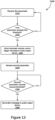
- Figure 13 depicts a method 1300 by a telematics device, such as the telematics device 200 or the telematics device 201.
- the method 1300 starts at step 1310.
- the telematics device receives a first parameter.
- the first parameter may be an engine parameter which is part of the asset data 112, such as the engine RPM, ignition signal, engine load, battery voltage, seat belt use, reversing, oil pressure, or engine coolant temperature.
- the parameter may be part of the sensor data 205 gathered from the sensors 204.
- the sensor data 205 may include accelerometer data indicating conditions such as harsh braking, hard acceleration, or collision.
- the sensor data 205 may be gyroscope data or orientation information, which when combined with accelerometer data may indicate harsh cornering or impaired driving.
- the first parameter may also comprise location data 207 provided by the location module 206.
- the location data 207 may be used to determine whether the vehicle to which the telematics device is coupled has entered a zone, left a zone, is within a particular distance from a zone.
- the location data 207 may also indicate the current speed of the vehicle and thus indicate whether the vehicle is traveling over a particular speed or over a speed limit.
- the telematics device compares the first parameter with a first threshold.
- the comparison is in accordance with the conditions set for a particular rule as discussed above.
- the first parameter is an engine parameter, such as the coolant temperature
- the first threshold may be a temperature value that indicates a slightly elevated coolant temperature. For example, if an engine coolant temperature of 85 degrees Celsius is normal and an engine coolant temperature of 100 degrees Celsius is too hot, then the first threshold may be set at a temperature of 90 or 95 degrees Celsius.
- the first threshold represents speed and a speeding rule has a condition to generate an alert when the speed is 10 Km/h over the speeding limit, then the first threshold may be set to 7 Km/h over the speeding limit.
- the first threshold represents a value that is close to but not equal to a second threshold that generates a notification in the form of an alert in accordance with the condition set in a rule.
- step 1320 If the first parameter does not exceed the first threshold, then control stays at step 1320. If the first parameter exceeds the first threshold, then control goes to step 1330.
- an automatic volume control trigger message 1022 to an audio output device coupled to the telematics device, such as the audio output expander 1200.
- the automatic volume control trigger message 1022 may be in the form of a frame or a hardware signal.
- the automatic volume control trigger message 1022 causes the audio output expander 1200 to initiate an automatic volume control procedure.
- the automatic volume control procedure includes powering up the microphone 1012 and the audio input module 1013, reading audio input from the audio input module 1013, the audio input indicative of ambient noise, and adjusting the audio output level of the speech synthesizer 1040.
- the telematics device receives a second parameter.
- the second parameter is of the same type as the first parameter.
- step 1350 if the second parameter does not exceed a second threshold, then control stays in step 1350, i.e., more values of the second parameter are read. If the second parameter exceeds the second threshold then control goes to step 1360.
- the second parameter may also be a vehicle speed.
- the first parameter read is a speed which may be at 116 Km/h and is determined to be greater than a first threshold of 115 Km/h.
- the second parameter read may also be a speed so that it may be compared with a second threshold of 120 Km/h.
- the telematics device sends a notification, for example in the form of an alert message, to the audio output device, such as the audio output expander 1200 so that the alert message may be played as an audible alert message.
- the first parameter and the second parameter are of the same type. In some embodiments, the first parameter and the second parameter are not of the same type.
- the speeding rule of Figure 8 which has a condition that the speed is greater than the speed limit by 10 Km/h and that this condition persists for 20 seconds.
- the first parameter read is the speed.
- the second parameter is time. In other words, the time from the instance at which the speed has exceeded the speed limit by 10 Km/h is the second parameter and the second threshold is 20 seconds. In this case, the first parameter has to remain above the first threshold until the second parameter has exceeded the second threshold or the notification message is not sent to the audio output device.
- the telematics device receives a first parameter of a first type.
- the step 1410 is similar to the step 1310 of Figure 13 ; the telematics device sends an automatic volume control trigger message 1022 to an audio output device coupled to the telematics device, such as the audio output expander 1200.
- step 1420 the telematics device checks whether the first parameter has exceeded the first threshold. If the first parameter has not exceeded the first threshold, then control goes back to step 1410 to read another value of the first parameter. The steps 1410 and 1420 are repeated until the first parameter exceeds the first threshold. If the first parameter has exceeded the first threshold, then control goes to step 1430.
- Step 1430 is similar to step 1330 of Figure 13 .
- the telematics device receives a second parameter of a second type.
- the first parameter may be a vehicle speed
- the second parameter may be a distance traveled or a duration since the first parameter has exceeded the first threshold.
- the telematics device checks whether the second parameter of the second type has exceeded a second threshold. If the second parameter has not exceeded the second threshold, then control goes back to step 1440, where another value of the second parameter is read. The steps 1440 and 1450 are repeated until the second parameter exceeds the second threshold. If the second parameter has exceeded the second threshold, then control proceeds to step 1452.
- the second parameter exceeds a second threshold while the first parameter has changed in value and no longer exceeds the first threshold. This may particularly be true if it takes time for the second parameter to exceed the second threshold (i.e., if the steps 1440 and 1450 are repeated for some time until the second parameter exceeds the second threshold). During that time, the first parameter may drop below the first threshold in which case the condition of the rule that requires that the first parameter exceeds the firs threshold and that the second parameter exceeds the second threshold may not be satisfied. Accordingly, in some embodiments the telematics device first verifies that the first parameter has not dropped below the first threshold.
- Verifying that the first parameter has not dropped below the first threshold may comprise receiving a second instance of the first parameter and comparing it with the second threshold. For example, at step 1452, the telematics device reads a second instance of the first parameter. Then at step 1455 the telematics device checks whether the first parameter has dropped below the first threshold. If the first parameter has dropped below the first threshold, then the condition for the rule will not be satisfied. Accordingly, control goes back to step 1410. If the first parameter has not dropped below the first threshold, then the condition for the rule will be satisfied. Accordingly, control goes to step 1460.
- Step 1460 is similar to step 1360 of the method 1300 of Figure 13 .
- the audio components are integral to the telematics device instead of being part of an audio output expander.
- a telematics device 203 having an integrated audio input module 213, an integrated power control module 232, an integrated microphone 242, an integrated speech synthesizer 245, and an integrated speaker 260.
- the aforementioned components have similar functionality as the audio input module 1013, the power control module 1032, the microphone 1012, the speech synthesizer 1040, and the speaker 1060.
- the telematics device 203 determines that a first threshold related to a rule parameter has been exceeded.
- the controller 230 signals the power control module to enable both the microphone 242 and the audio input module 213.
- the controller 230 also executes computer programming instructions which perform an automatic volume control procedure.
- the microphone 242 and the audio input module 213 provide a measure of the ambient noise to the controller 230.
- the controller 230 adjusts the audio output level of the speech synthesizer.
- the controller 230 may signal the power control module 232 to power off the audio input module 213 and the microphone 242.
- the controller 230 sends an alert message 1020 to the speech synthesizer 245 so it may be played back over the speaker 260 as an audible alert message.
- a normal device voltage of a battery may be 13.6 volts. If there is an alternator problem, the battery voltage may be 13V. If the undercharging condition persists, the battery voltage may drop further and reach 12.5V.
- the first threshold may be 13V and the second threshold may be 12.5V. In this case, it is said that the first threshold is exceeded if the battery voltage drops to 13V or lower, and that the second threshold is exceeded if the battery voltage drops to 12.5V or lower.
- Embodiments have been described where the techniques are implemented in circuitry and/or computer-executable instructions. It should be appreciated that some embodiments may be in the form of a method or process, of which at least one example has been provided. The acts performed as part of the method or process may be ordered in any suitable way. Accordingly, embodiments may be constructed in which acts are performed in an order different than illustrated, which may include performing some acts simultaneously, even though shown as sequential acts in illustrative embodiments.
- Various aspects of the embodiments described above may be used alone, in combination, or in a variety of arrangements not specifically discussed in the embodiments described in the foregoing and is therefore not limited in its application to the details and arrangement of components set forth in the foregoing description or illustrated in the drawings. For example, aspects described in one embodiment may be combined in any manner with aspects described in other embodiments.
Landscapes
- Engineering & Computer Science (AREA)
- Physics & Mathematics (AREA)
- Health & Medical Sciences (AREA)
- Acoustics & Sound (AREA)
- Multimedia (AREA)
- General Physics & Mathematics (AREA)
- Theoretical Computer Science (AREA)
- Audiology, Speech & Language Pathology (AREA)
- Human Computer Interaction (AREA)
- General Health & Medical Sciences (AREA)
- Signal Processing (AREA)
- General Engineering & Computer Science (AREA)
- Computational Linguistics (AREA)
- Electromagnetism (AREA)
- Otolaryngology (AREA)
- Alarm Systems (AREA)
Abstract
Description
- The present disclosure generally relates to vehicle telematics, and more specifically to devices and methods for controlling audio output in a telematics system.
- A telematics system may gather asset data using a telematics device. The telematics device may be integrated into or located onboard the asset. The asset may be a vehicle ("vehicular asset") or some stationary equipment. The telematics device may collect the asset data from the asset through a data connection with the asset. In the case of a vehicular asset, the telematics device may gather the asset data through an onboard diagnostic port (OBD). The gathered asset data may include engine revolutions-per-minute (RPM), battery voltage, fuel level, tire pressure, oil temperature, or any other asset data available through the diagnostic port. Additionally, the telematics device may gather sensor data pertaining to the asset via sensors on the telematics device. For example, the telematics device may have temperature and pressure sensors, inertial measurement units (IMU), optical sensors, and the like. Furthermore, the telematics device may gather location data pertaining to the asset from a location module on the telematics device. When the telematics device is coupled to the asset, the gathered sensor data and location data pertain to the asset. The gathered asset data, sensor data and location data may be received and recorded by a technical infrastructure of the telematics system, such as a telematics server, and used in the provision of fleet management tools, for telematics services, or for further data analysis.
- In one aspect of the present disclosure, there is provided a method in a telematics device coupled to a vehicle. The method comprises determining that a first parameter of a first type exceeds a first threshold, in response to determining that the first parameter is greater than the first threshold sending an automatic volume control trigger message to an audio output device coupled to the telematics device, determining that a second parameter of a second type exceeds a second threshold, and in response to determining that the second parameter exceeds the second threshold, sending an alert message to the audio output device. Advantageously, the audio output device receives the automatic volume control trigger message before the alert message thus providing the audio output device with an opportunity to perform an automatic volume control procedure.
- The second type may be the same as the first type. Alternatively, the second type may be different from the first type. For example, the first time may be a vehicle operating parameter and the second type may be time. Alternatively, the first type and the second type may both be the same vehicle parameter.
- Determining that the first parameter exceeds the first threshold may comprise determining that a value of the first parameter is greater than the first threshold.
- Determining that the first parameter exceeds the first threshold may comprise determining that a value of the first parameter is lower than the first threshold.
- Determining that the second parameter exceeds the second threshold may comprise determining that the second parameter exceeds the first threshold, when the second type is the same as the first type.
- Determining that the first parameter exceeds the first threshold may comprise receiving the first parameter and comparing the first parameter against the first threshold.
- Determining that the second parameter exceeds the second threshold may comprise receiving the second parameter and comparing the second parameter against the second threshold.
- The method may further comprise determining that the first parameter has not dropped below the first threshold in response to determining that the second parameter exceeds the second threshold.
- Determining that the first parameter has not dropped below the first threshold may comprise reading the first parameter and comparing the first parameter against the first threshold.
- The audio output device may comprise an audio output expander coupled to the telematics device via an input/output expander interface.
- Sending an automatic volume control trigger message may comprise sending a message that powers up a plurality of audio components for detecting ambient noise. Advantageously, the audio components for detecting ambient noise are now always powered up thus consuming power and potentially draining a power source, such as a battery. Instead, the audio components for detecting ambient noise are only powered up when there is a potential that an alert message may need to be played on the audio output device.
- The plurality of audio components for detecting ambient noise may comprise a microphone and an audio input module.
- The message that powers up the plurality of audio components for detecting ambient noise may also invoke an automatic volume control procedure for adjusting an audio output level of the audio output device. Invoking an automatic volume control procedure upon powering up the audio components for detecting ambient noise, serves to adjust the output volume level in advance of the need to play the alert message. This ensures that the alert message is played at an adequate output level that overcomes ambient noise while at the same time not being too loud as to disturb the vehicle operator.
- Adjusting the audio output level of the audio output device may comprise adjusting the audio output level of a speech synthesizer that converts the alert message to an audible alert message.
- In another aspect of the present disclosure, there is provided a telematics device. The telematics device comprises a controller, an asset interface coupled to the controller, and a memory coupled to the controller. The memory is storing machine-executable instructions which, when executed by the controller, configure the telematics device to determine that a first parameter of a first type exceeds a first threshold, in response to determining that the first parameter is greater than the first threshold, send an automatic volume control trigger message to an audio output device coupled to the telematics device, determine that a second parameter of a second type exceeds a second threshold, and in response to determining that the second parameter exceeds the second threshold, send an alert message to the audio output device. Advantageously, the audio output device receives the automatic volume control trigger message before the alert message thus providing the audio output device with an opportunity to perform an automatic volume control procedure.
- In yet another aspect of the present disclosure, there is provided a method in a telematics system including a telematics device and an audio output device coupled to the telematics device. The method comprises determining, by the telematics device, that a first parameter of a first type exceeds a first threshold, in response to determining that the first parameter exceeds the first threshold sending by the telematics device an automatic volume control trigger message to the audio output device, and receiving the automatic volume control trigger message at the audio output device. The method further comprises invoking at the audio output device an automatic volume control procedure in response to receiving the automatic volume control trigger message and determining that a second parameter of a second type exceeds a second threshold. The method additionally comprises determining by the telematics device that the second parameter exceeds the second threshold, sending by the telematics device an alert message to the audio output device in response to receiving the alert message at the audio output device, and playing by the audio output device an audible alert message based on the alert message. Advantageously, the audio output device receives the automatic volume control trigger message before the alert message thus providing the audio output device with an opportunity to perform an automatic volume control procedure.
- Invoking the automatic volume control procedure may comprise powering up a plurality of audio devices for detecting ambient noise. Advantageously, the audio components for detecting ambient noise are now always powered up thus consuming power and potentially draining a power source, such as a battery. Instead, the audio components for detecting ambient noise are only powered up when there is a potential that an alert message may need to be played on the audio output device
- Playing the audible alert message based on the alert message may comprise providing the alert message to a speech synthesizer of the audio output device.
- The audio output device may comprise an audio output expander coupled to the telematics device via an input/output expander interface.
- In a further aspect of the present disclosure, there is provided a method in an audio playback device connected to a telematics device which is coupled to a vehicle. The method comprises receiving an alert message to be played on the audio playback device, in response to receiving the alert message, powering up a microphone and an audio input module and starting an automatic volume control procedure, and when the automatic volume control procedure is completed, sending the alert message to a speech synthesizer for playback over a speaker coupled to the speech synthesizer.
- Exemplary non-limiting embodiments of the present invention are described with reference to the accompanying drawings in which:
-
Figure 1 is a schematic diagram of a telematics system including a plurality of telematics devices coupled to a plurality of assets; -
Figure 2 is a block diagram showing a telematics device coupled to an asset; -
Figure 3 is a block diagram showing a telematics device coupled to an asset and to an input/output (I/O) expander; -
Figure 4 is a block diagram showing an asset having a telematics device integrated therein and I/O expander coupled thereto; -
Figure 5A is a message sequence diagram showing server-side rules configuration and alert generation in a telematics system, in accordance with embodiments of the present disclosure; -
Figure 5B is a message sequence diagram showing device-side rules configuration and alert generation, in accordance with embodiments of the present disclosure; -
Figure 6 is a user interface for selecting a vehicle or a group, and selecting a category of rules, in accordance with embodiments of the present disclosure; -
Figure 7 is a user interface for selecting a safety rule for a selected vehicle or group, in accordance with embodiments of the present disclosure; -
Figure 8 is a user interface for editing the conditions of a speeding rule, in accordance with embodiments of the present disclosure; -
Figure 9 is a user interface for selecting notification options for the speeding rule ofFigure 8 , in accordance with embodiments of the present disclosure; -
Figure 10 is a block diagram showing an asset tracking device coupled to an asset and to an audio output expander having volume control; -
Figure 11 is a block diagram showing an asset tracking device coupled to an asset and to an audio output expander having automatic volume control capability, in accordance with an embodiment of the present disclosure; -
Figure 12 is a block diagram showing an asset tracking device coupled to an asset and to an audio output expander having automatic volume control capability, in accordance with another embodiment of the present disclosure; -
Figure 13 is a flow chart depicting a method by a telematics device for providing an audible alert message using an audio output device, in accordance with an embodiment of the present disclosure; -
Figure 14 is a flow chart depicting a method by a telematics device for providing an audible alert message using an audio output device, in accordance with another embodiment of the present disclosure; and -
Figure 15 is a block diagram showing a telematics device having integrated audio output components, in accordance with some embodiments of the present disclosure. - A large telematics system may collect data from a high number of assets, either directly or through telematic devices. A telematics device may refer to a self-contained device installed at an asset, or a telematics device that is integrated into the asset itself. In either case, it may be said that telematics data is being captured or gathered by the telematics device.
Figure 1 shows a high-level block diagram of atelematics system 101. Thetelematics system 101 includes atelematics server 130, (N) telematics devices shown as telematics device 200_1, telematics device 200_2...through telematics device 200_N ("telematics device 200"), anetwork 50,administration terminal 140, and operator terminals 150_1, 150_2...through 150_N ("theoperator terminals 150").Figure 1 also shows a plurality of (N) assets named as asset 100_1, asset 100_2...asset 100_N ("asset 100") coupled to the telematics device 200_1, telematics device 200_2...telematics device 200_N, respectively. Additionally,Figure 1 shows a plurality of satellites 170_1, 170_2 and 170_3 ("thesatellites 170") in communication with thetelematics devices 200 for facilitating navigation. - The
assets 100 shown are in the form of vehicles. For example, the asset 100_1 is shown as a truck, which may be part of a fleet that delivers goods or provides services. The asset 100_2 is shown as a passenger car that typically runs on an internal combustion engine (ICE). The asset 100_3 is shown as an electric vehicle (EV). Other types of vehicles, which are not shown, are also contemplated in the various embodiments of the present disclosure, including but not limited to, farming vehicles, construction vehicles, military vehicles, and the like. - The
telematics devices 200 are electronic devices which are coupled toassets 100 and configured to capture asset data from theassets 100. For example, inFigure 1 the telematics device 200_1 is coupled to the asset 100_1. Similarly, the telematics device 200_2 is coupled to the asset 100_2 and the telematics device 200_3 is coupled to the asset 100_3. The components of atelematics device 200 are explained in further detail with reference toFigure 2 . - The
network 50 may be a single network or a combination of networks such as a data cellular network, the Internet, and other network technologies. Thenetwork 50 may provide connectivity between thetelematics devices 200 and thetelematics server 130, between theadministration terminal 140 and thetelematics server 130, and between theoperator terminals 150 and thetelematics server 130. - The
telematics server 130 is an electronic device executing machine-executable programming instructions which enable thetelematics server 130 to store and analyze telematics data. Thetelematics server 130 may be a single computer system or a cluster of computers. Thetelematics server 130 may be running an operating system such as Linux, Windows, Unix, or any other equivalent operating system. Alternatively, thetelematics server 130 may be a software component hosted on a cloud service, such as Amazon Web Service (AWS). Thetelematics server 130 is connected to thenetwork 50 and may receive telematics data from thetelematics devices 200. Thetelematics server 130 may have a plurality of software modules for performing data analysis and analytics on the telematics data to obtain useful asset information about theassets 100. Thetelematics server 130 may be coupled to atelematics database 132 for storing telematics data and/or the results of the analytics which are related to theassets 100. The asset information stored may include operator information about the operators 10 corresponding to the assets. Thetelematics server 130 may communicate the asset data and/or the operator information pertaining to anasset 100 to one or more of: theadministration terminal 140, and theoperator terminal 150. - The
satellites 170 may be part of a global navigation satellite system (GNSS) and may provide location information to thetelematics devices 200. The location information may be processed by a location module on thetelematics device 200 to provide location data indicating the location of the telematics device 200 (and hence the location of theasset 100 coupled thereto). Atelematics device 200 that can periodically report an asset's location is often termed an "asset tracking device". - The
administration terminal 140 is an electronic device, which may be used to connect to thetelematics server 130 to retrieve data and analytics related to one ormore assets 100 or to issue commands to one ormore telematics device 200 via thetelematics server 130. Theadministration terminal 140 is shown as a laptop computer, but may also be a desktop computer, a tablet (not shown), or a smartphone. Theadministration terminal 140 may run a web browser or a custom application which allows retrieving data and analytics, pertaining to one ormore assets 100, from thetelematics server 130 via a web interface of thetelematics server 130. Theadministration terminal 140 may also be used to issue commands to one ormore telematics device 200 via thetelematics server 130. Afleet manager 20 may communicate with thetelematics server 130 using theadministration terminal 140. In addition to retrieving data and analytics, theadministration terminal 140 allows thefleet manager 20 to set alerts and geofences for keeping track of theassets 100, receiving notifications of deliveries, and so on. - The
operator terminals 150 are electronic devices, such as smartphones or tablets. Theoperator terminals 150 are used by operators 10 (for example, vehicle drivers) of theassets 100 to both track and configure the usage of theassets 100. For example, as shown inFigure 1 , the operator 10_1 has the operator terminal 150_1, the operator 10_2 has the operator terminal 150_2, and the operator 10_N has the operator terminal 150_N. Assuming the operators 10 all belong to a fleet of vehicles, each of the operators 10 may operate any of theassets 100. For example,Figure 1 shows that the operator 10_1 is associated with the asset 100_1, the operator 10_2 is associated with the asset 100_2, and the operator 10_N is associated with the asset 100_N. However, any operator 10 may operate anyasset 100 within a particular group of assets, such as a fleet. Theoperator terminals 150 are in communication with thetelematics server 130 over thenetwork 50. Theoperator terminals 150 may run at least one asset configuration application. The asset configuration application may be used by an operator 10 to inform thetelematics server 130 that theasset 100 is being currently operated by the operator 10. For example, the operator 10_2 may use an asset configuration application on the operator terminal 150_2 to indicate that the operator 10_2 is currently using the asset 100_2. Thetelematics server 130 updates thetelematics database 132 to indicate that the asset 100_2 is currently associated with the operator 10_2. Additionally, the asset configuration application may be used to report information related to the operation duration of the vehicle, the number of stops made by the operator during their working shift, and so on. Furthermore, the asset configuration application may allow the operator to configure thetelematics device 200 coupled to theasset 100 that the operator 10 is operating. - In operation, a
telematics device 200 is coupled to anasset 100 to capture asset data. The asset data may be combined with location data obtained by thetelematics device 200 from a location module in communication with thesatellites 170 and/or sensor data gathered from sensors in thetelematics device 200 or another device coupled to thetelematics device 200. The combined asset data, location data, and sensor data may be termed "telematics data." Thetelematics device 200 sends the telematics data, to thetelematics server 130 over thenetwork 50. Thetelematics server 130 may process, aggregate, and analyze the telematics data to generate asset information pertaining to theassets 100 or to a fleet of assets. Thetelematics server 130 may store the telematics data and/or the generated asset information in thetelematics database 132. Theadministration terminal 140 may connect to thetelematics server 130, over thenetwork 50, to access the generated asset information. Alternatively, thetelematics server 130 may push the generated asset information to theadministration terminal 140. Additionally, the operators 10, using theiroperator terminals 150, may indicate to thetelematics server 130 whichassets 100 they are associated with. Thetelematics server 130 updates thetelematics database 132 accordingly to associate the operator 10 with theasset 100. Furthermore, thetelematics server 130 may provide additional analytics related to the operators 10 including work time, location, and operating parameters. For example, for vehicle assets, the telematics data may include turning, speeding, and braking information. Thetelematics server 130 can correlate the telematics data to the vehicle's driver by querying the asset database 310. Afleet manager 20 may use theadministration terminal 140 to set alerts for certain activities pertaining to theassets 100. When criteria for an alert is met, thetelematics server 130 sends a message to theadministration terminal 140 to notify afleet manager 20, and may optionally send alerts to theoperator terminal 150 to notify an operator 10 of the alert. For example, a vehicle driver operating the vehicle outside of a service area or hours of service may receive an alert on theiroperator terminal 150. Afleet manager 20 may also use theadministration terminal 140 to configure atelematics device 200 by issuing commands thereto via thetelematics server 130. Alerts may also be sent to thetelematics device 200 to generate an alert to the driver such as a beep, a displayed message, or an audio message. - Further details relating to the
telematics device 200 and how it interfaces with anasset 100 are shown with reference toFigure 2. Figure 2 depicts anasset 100 and atelematics device 200 coupled thereto. Selected relevant components of each of theasset 100 and thetelematics device 200 are shown. - The
asset 100 may have a plurality of electronic control units (ECUs). An ECU is an electronic module which interfaces with one or more sensors for gathering information from theasset 100. For example, an engine coolant temperature (ECT) ECU may contain a temperature sensor and a controller for converting the measured temperature into digital data representative of the oil temperature. Similarly, a battery voltage ECU may contain a voltage sensor for measuring the voltage at the positive battery terminal and a controller for converting the measured voltage into digital data representative of the battery voltage. A vehicle may, for example, have around seventy ECUs. For simplicity, only a few of the ECUs 110 are depicted inFigure 2 . For example, in the depicted embodiment theasset 100 has three ECUs shown as the ECU 110A, theECU 110B, and theECU 110C ("the ECUs 110"). The ECU 110A, theECU 110B, and theECU 110C are shown to be interconnected via an asset communications bus. One example of an asset communications bus is a Controller Area Network (CAN) bus. For example, inFigure 2 the ECUs 110 are interconnected using theCAN bus 104. The ECUs 110 send and receive information to one another in CAN data frames by placing the information on theCAN bus 104. When an ECU 110 places information on theCAN bus 104, other ECUs 110 receive the information and may or may not consume or use that information. Different protocols may be used to exchange information between the ECUs over a CAN bus. For example, ECUs 110 in trucks and heavy vehicles use the Society of Automotive Engineering (SAE) J1939 protocol to exchange information over aCAN bus 104. Most passenger vehicles use the SAE J1979 protocol, which is commonly known as On-Board Diagnostic (OBD) protocol to exchange information between ECUs 110 on theirCAN bus 104. In industrial automation, ECUs use a CANOpen protocol to exchange information over aCAN bus 104. Anasset 100 may allow access to information exchanged over theCAN bus 104 via aninterface port 102. For example, if theasset 100 is a passenger car, then theinterface port 102 is most likely an OBD-II port. Data accessible through theinterface port 102 is termed theasset data 112. In some embodiments, theinterface port 102 includes a power interface for providing electric power to atelematics device 200 connected thereto. - The
telematics device 200 includes acontroller 230 coupled to amemory 240, aninterface layer 210 and anetwork interface 220. Thetelematics device 200 also includes one ormore sensors 204 and alocation module 206 coupled to theinterface layer 210. Thetelematics device 200 may also contain some optional components, shown in dashed lines inFigure 2 . For example, thetelematics device 200 may contain one or more of: a near-field communications (NFC) module such asNFC module 260, a short-range wireless communications module 270, and a wired communications module such as a serial communications module 280. In some embodiments (not shown), thetelematics device 200 may have a dedicated power source or a battery. In other embodiments, thetelematics device 200 may receive power directly from theasset 100, via theinterface port 102. Thetelematics device 200 shown is an example. Some of the components shown in solid lines may also be optional and may be implemented in separate modules. For example, some telematics devices (not shown) may not have alocation module 206 and may rely on an external location module for obtaining thelocation data 207. Some telematics devices may not have anysensors 204 and may rely on external sensors for obtainingsensor data 205. - The
controller 230 may include one or any combination of a processor, microprocessor, microcontroller (MCU), central processing unit (CPU), processing core, state machine, logic gate array, application-specific integrated circuit (ASIC), field-programmable gate array (FPGA), or similar, capable of executing, whether by software, hardware, firmware, or a combination of such, the actions performed by thecontroller 230 as described herein. Thecontroller 230 may have an internal memory for storing machine-executable programming instructions to conduct the methods described herein. - The
memory 240 may include read-only-memory (ROM), random access memory (RAM), flash memory, magnetic storage, optical storage, and similar, or any combination thereof, for storing machine-executable programming instructions and data to support the functionality described herein. Thememory 240 is coupled to thecontroller 230 thus enabling thecontroller 230 to execute the machine-executable programming instructions stored in thememory 240 and to access the data stored therein. Thememory 240 may contain machine-executable programming instructions, which when executed by thecontroller 230, configures thetelematics device 200 for receivingasset data 112 from theasset 100 via theasset interface 202, and for receivingsensor data 205 from thesensors 204 and/orlocation data 207 from thelocation module 206 via thesensor interface 208. Thememory 240 may also contain machine-executable programming instructions for combiningasset data 112,sensor data 205 andlocation data 207 intotelematics data 212. Additionally, thememory 240 may further contain instructions which, when executed by thecontroller 230, configures thetelematics device 200 to transmit thetelematics data 212 via thenetwork interface 220 to atelematics server 130 over anetwork 50. In some embodiments, thememory 240 only stores data, and the machine-executable programming instructions for conducting the aforementioned tasks are stored in an internal memory of thecontroller 230. - The
location module 206 may be a global positioning system (GPS) transceiver or another type of location determination peripheral that may use, for example, wireless network information for location determination. Thelocation module 206 is coupled to thecontroller 230 and provideslocation data 207 thereto. Thelocation data 207 may be in the form of a latitude and longitude, for example. - The
sensors 204 may be one or more of: a temperature sensor, a pressure sensor, an optical sensor, a motion sensor such as an accelerometer, a gyroscope, or any other suitable sensor indicating a condition pertaining to theasset 100 to which thetelematics device 200 is coupled. The sensors providesensor data 205 to thecontroller 230 via thesensor interface 208. - The
interface layer 210 may include asensor interface 208 and anasset interface 202. Thesensor interface 208 is configured for receiving thesensor data 205 from thesensors 204. For example, thesensor interface 208 interfaces with thesensors 204 and receives thesensor data 205 therefrom. Theasset interface 202 receivesasset data 112 from theasset 100. In the depicted embodiment, theasset interface 202 is coupled to theinterface port 102 of theasset 100. Theasset data 112, received at thetelematics device 200, from theasset 100 may be in the form of data messages, such as CAN data frames. Theasset data 112 may describe one or more of any of: a property, a state, and an operating condition of theasset 100. For example, where theasset 100 is a vehicle, the data may describe the speed at which the vehicle is traveling, a state of the vehicle (off, idle, or running), or an engine operating condition (e.g., engine oil temperature, engine revolutions-per-minutes (RPM), or a battery voltage). In addition to receiving theasset data 112, in some embodiments theasset interface 202 may also receive power from theasset 100 via theinterface port 102. Theinterface layer 210 is coupled to thecontroller 230 and provides both theasset data 112 and thesensor data 205 to thecontroller 230. - The
network interface 220 may include a cellular modem, such as an LTE-M modem, CAT-M modem, other cellular modem, Wi-Fi modem, or any other communication device configured for communication via thenetwork 50 with which to communicate with thetelematics server 130. Thenetwork interface 220 may be used to transmittelematics data 212 obtained from theasset 100 to thetelematics server 130 for a telematics service or other purposes. Thenetwork interface 220 may also be used to receive instructions from thetelematics server 130 for configuring thetelematics device 200 in a certain mode and/or requesting a particular type of theasset data 112 from theasset 100. - The
NFC module 260 may be an NFC reader which can read information stored on an NFC tag. TheNFC module 260 may be used to confirm the identity of the operator 10 by having the operator 10 tap an NFC tag onto thetelematics device 200 such that the NFC tag is read by theNFC module 260. The information read from the NFC tag may be included in thetelematics data 212 sent by thetelematics device 200 to thetelematics server 130. - The short-range wireless communications module 270 is a component intended for providing short-range wireless communication capability to the
telematics device 200. The short-range wireless communications module 270 may be a BluetoothTM. wireless fidelity (Wi-Fi), ZigbeeTM, or any other short-range wireless communications module. The short-range wireless communications module 270 allows other devices to communicate with thetelematics device 200 over a short-range wireless network. - The serial communications module 280 is an example of a wired communications module. The serial communications module 280 is an electronic peripheral for providing serial wired communications to the
telematics device 200. For example, the serial communications module 280 may include a universal asynchronous receiver transmitter (UART) providing serial communications per the RS-232 protocol. Alternatively, the serial communications module 280 may be a serial peripheral interface (SPI) bus, or an inter-integrated circuit (I2C) bus. As another example, the serial communications module 280 may be a universal serial bus (USB) transceiver. - In operation, an ECU 110, such as the ECU 110A, the
ECU 110B, or theECU 110C communicates asset data over theCAN bus 104. The asset data exchanged, between the ECUs 110, over theCAN bus 104 are accessible via theinterface port 102 and may be retrieved as theasset data 112 by thetelematics device 200. Thecontroller 230 of thetelematics device 200 receives theasset data 112 via theasset interface 202. Thecontroller 230 may also receivesensor data 205 from thesensors 204 over thesensor interface 208. Furthermore, thecontroller 230 may receivelocation data 207 from thelocation module 206. Thecontroller 230 combines theasset data 112 with thesensor data 205 and thelocation data 207 to obtain thetelematics data 212. Thecontroller 230 transmits thetelematics data 212 to thetelematics server 130 over thenetwork 50 via thenetwork interface 220. Optionally, an operator 10 may tap an NFC tag to theNFC module 260 to identify themself as the operator 10 of theasset 100. Additionally, an external peripheral, such as a GPS receiver, may connect with thetelematics device 200 via the short-range wireless communications module 270 or the serial communications module 280 for providing location information thereto. In some embodiments, thetelematics device 200 may receive, via thenetwork interface 220, commands from thetelematics server 130. The received commands instruct thetelematics device 200 to be configured in a particular way. For example, the received commands may configure the way in which the telematics device gathersasset data 112 from theasset 100 as will be described in further detail below. - The
telematics data 212 which is composed ofasset data 112 gathered from theasset 100 combined with thesensor data 205 and thelocation data 207 may be used to derive useful data and analytics, by thetelematics server 130. However, there are times when additional data, which is not provided by theasset 100, thesensors 204 or thelocation module 206 may be needed. Thetelematics device 200 may have a limited number ofsensors 204 such as accelerometers or gyroscopes providing limited information about the motion of theasset 100 on which thetelematics device 200 is deployed. Thelocation module 206 may provide location and direction information. However, in some cases, more information may be needed to derive useful data and analytics pertaining to theasset 100. One example of information that is not typically provided by thetelematics device 200 is video capture data. Another example of information that is not typically provided by thetelematics device 200 is any proprietary signaling provided by devices which does not follow any of the standard protocols (OBD-II, J1939 or CANOpen). Some equipment may not have a CAN bus and may provide proprietary digital and/or analog signals. Examples of such devices include industrial equipment, winter maintenance equipment such as salt spreaders, farming equipment, and the like. Additionally, thetelematics device 200 may not have anNFC module 260 or a short-range wireless communications module 270 thus limiting its connectivity capabilities. - To capture and provide information or services not provided by the
asset 100 or the telematics device, to produce an output, or to perform an action not supported by the telematics device, thetelematics device 200 may be modified to allow an input/output expander device ("I/O expander") to connect thereto, as shown inFigure 3. Figure 3 shows atelematics device 201 coupled to anasset 100. An I/O expander 300 is coupled to thetelematics device 201. - The
asset 100 is similar to theasset 100 ofFigure 2 and therefore the internal components thereof are not shown inFigure 3 for simplicity. - The
telematics device 201 has a somewhat similar configuration as thetelematics device 200 ofFigure 2 , but some of the optional components have been removed. Furthermore, thetelematics device 201 adds an I/O expander interface 250 for interfacing with the I/O expander 300. The I/O expander interface 250 is coupled to thecontroller 230 and may be configured for exchanging I/O expander data 312 with the I/O expander 300. - The I/
O expander 300 ofFigure 3 is an example I/O expander which is designed to provide additional connectivity options to atelematics device 200, which has more limited features than the one shown inFigure 2 . For example, thetelematics device 201 shown inFigure 3 does not have an NFC module, a short-range wireless communications module, or a serial communications module. Instead, thetelematics device 201 has an I/O expander interface 250. - The I/
O expander 300 may be an input device configured to capture additional data such as video frames, audio frames, or proprietary signals and provide that data to thetelematics device 201. Alternatively, or additionally, the I/O expander 300 may be configured as an output device and may include a display for displaying information and/or an audio output device for broadcasting messages pertaining to theasset 100. - An I/
O expander 300, which connects with thetelematics device 201, varies in complexity depending on the purpose thereof.Figure 3 shows an I/O expander 300 containing several components which may or may not all be present in other I/O expanders. For example, the I/O expander 300 includes acontroller 330, anNFC module 260, anoutput device 340, a short-range communications module 370, animage sensor 390, aserial communications module 380, anuplink interface 350 and adownlink interface 520. - The
controller 330 may be similar to thecontroller 230 ofFigure 3 . In some embodiments, thecontroller 330 is a microcontroller with versatile I/O capabilities. For example, thecontroller 330 may be a microcontroller which has a plurality of I/O ports such as general-purpose inputs and outputs (GPIOs), serial ports, analog inputs, and the like. In some embodiments, thecontroller 330 may have built-in persistent memory such as flash memory on which machine-executable programming instructions for conducting the functionality of the I/O expander 300 may be stored. In other embodiments, thecontroller 330 may be coupled to a persistent memory module (not shown) that contains the machine-executable programming instructions for conducting the functionality of the I/O expander 300. Thecontroller 330 may also have built-in volatile memory, such as random-access memory (RAM) for storing data. Alternatively, the I/O expander 300 may be connected to an external volatile memory for storing data. - The
output device 340 receives data from thecontroller 330 and performs an output function. For example, theoutput device 340 may include a display for displaying information received from thecontroller 330. As another example, theoutput device 340 may include a speech synthesizer and a speaker for displaying audible information received from thecontroller 330. As yet another example, theoutput device 340 may be an output interface to a hardware device. For example, theoutput device 340 may be a motor controller that interfaces to an electric motor. - The
NFC module 360, short-range communications module 370, and theserial communications module 380 are similar to theNFC module 260, short-range wireless communications module 270, and the serial communications module 280 described above with reference toFigure 2 . - The
image sensor 390 may be a digital still camera or a digital video camera capable of capturing images. For example, theimage sensor 390 may be a road-facing dashboard camera for monitoring the road ahead. In other examples, theimage sensor 390 may be a driver-facing dashboard camera for identifying the operator 10 and/or their condition. - The
uplink interface 350 is an electronic peripheral interface coupled to thecontroller 330 and is used to provide data exchange and/or power capabilities to the I/O expander 300. Theuplink interface 350 allows the I/O expander 300 to transmit and receive I/O expander data. Theuplink interface 350 is configured to use the same protocol and signaling as the I/O expander interface 250 of thetelematics device 201. Accordingly, the I/O expander 300 may exchange the I/O expander data with thetelematics device 201. In some embodiments, theuplink interface 350 may also include power pins connected to corresponding power pins in the I/O expander interface 250, thus allowing the I/O expander 300 to be powered via thetelematics device 201. In other embodiments (not shown), the I/O expander 300 may have its own power source instead of or in addition to the power provided by thetelematics device 201 via theuplink interface 350. - The
downlink interface 520 is an electronic peripheral interface coupled to theuplink interface 350. Thedownlink interface 520 is configured to interface with theuplink interface 350 of another I/O expander 300 (as will be described below). Allowing theuplink interface 350 to connect to thedownlink interface 320 of another I/O expander allows the daisy chaining of I/O expanders. - In the above-mentioned figures, a telematics device is shown as a separate entity connected with a corresponding asset. The telematics device, however, may have its components integrated into the
asset 100 at the time of manufacture of theasset 100. This may be the case when theasset 100 is a connected car having an asset network interface. For example, with reference toFigure 4 , there is shown anasset 400 with the components of a telematics device integrated therein, in accordance with embodiments of the present disclosure. Theasset 400 is similar to theasset 100 but, being a connected asset such as a connected car, it has anasset network interface 122. In the depicted embodiment, thecontroller 230 is directly connected to the asset communications bus, which is aCAN bus 104 and may directly obtain theasset data 112 therefrom. Thesensors 204 and thelocation module 206 are also integrated into theasset 100 and provide thesensor data 205 and thelocation data 207 to thecontroller 230 as described above. Theasset network interface 122 belongs to theasset 400 and may be used by theasset 400 to communicate with an original equipment manufacturer (OEM) server, to a roadside assistance server, or for other purposes. Thecontroller 230 may utilize theasset network interface 122 for the transmission oftelematics data 212 provided by thecontroller 230. In order to support further not provided by the integrated peripherals such as thesensors 204 and thelocation module 206, the asset has an I/O expander interface 250 coupled to thecontroller 230 so that an I/O expander 300 may be connected to theasset 400 therethrough. Theasset 400 may have aninterface port 102 for connecting other devices other than atelematics device 200, such as a diagnostic tool including, but not limited to, an OBD-II reader device. - As discussed briefly above, the
telematics server 130 maintains a plurality of rules that trigger actions or alerts based on the receivedtelematics data 212. The rules may be configured by afleet manager 20 for example, using anadministration terminal 140. Thetelematics server 130 may, in response to receiving thetelematics data 212, send an alert condition to a telematics device to trigger an action thereon. Additionally, thetelematics server 130 may send the alert condition to theadministration terminal 140. As an example,Figure 5A is a message sequence diagram depicting amethod 500 of generating an alert condition based on rules andtelematics data 212, in accordance with embodiments of the present disclosure. - The
method 500 starts atstep 502. Atstep 502, afleet manager 20 may use anadministration terminal 140 to connect to thetelematics server 130 and configure some rules for a vehicle or a group of vehicles. Details of the user interface and the options for configuring the rules will be described below. Theadministration terminal 140 may connect to thetelematics server 130 by means of a web browser or a mobile application, for example. - At
step 504, thetelematics server 130 configures a plurality of rules for one or more vehicles selected in the input received from theadministration terminal 140 instep 502. Thetelematics server 130 may store the rules in thetelematics database 132 or internally within thetelematics server 130. - At
step 506, thetelematics device 200 sendstelematics data 212 to thetelematics server 130. Thetelematics server 130 receives thetelematics data 212 and may store thetelematics data 212 in thetelematics database 132 or in an internal storage. - At
step 508, thetelematics server 130 evaluates thetelematics data 212 in light of the rules. The evaluation oftelematics data 212 in light of the rules may generate an alert condition. For example, thetelematics data 212 may indicate excessive speed, harsh braking, hard cornering, or a mechanical failure with the vehicle to which thetelematics device 200 is coupled. Alternatively, thetelematics server 130 may determine that the location of thetelematics device 200 is within a geographic zone and that one of the rules stipulates that an alert must be generated. If the evaluation of thetelematics data 212 and the rules indicate an alert condition, then atstep 510, thetelematics server 130 sends a message indicating an alert condition to thetelematics device 200. An alert sent to thetelematics device 200 may be used to trigger an alert indication on thetelematics device 200. An alert indication on thetelematics device 200 may be a beep, a flashing of an LED (light emitting diode), a message displayed on a display such as an LCD (liquid crystal display), or a voice message played over an audio device. In addition to sending an alert to thetelematics device 200, thetelematics server 130, in response to evaluating thetelematics data 212 in light of the rules, may also send a message indicating an alert condition to theadministrator terminal 140 as shown instep 512. For example, afleet manager 20 may be interested in receiving an alert when a vehicle in the fleet is driving over the speed limit. - In some cases, the
telematics device 200 may evaluate theasset data 112,sensor data 205, andlocation data 207 and determine whether an alert condition has been satisfied. This is described with reference toFigure 5B . - Step 522 is similar to step 502 of
Figure 5A . An input on anadministration terminal 140 specifies telematics device-side rules for one or more vehicles. In this case the device-side rules are rules which thetelematics server 130 is to relay to thetelematics device 200 corresponding to the selected vehicles specified in the input provided at theadministration terminal 140. - At
step 524, thetelematics server 130 sends the device-side rules to thetelematics device 200. Thetelematics device 200 receives the device-side rules. - At
step 528, theasset 100 sendsasset data 112 to thetelematics device 200. Thetelematics device 200 receives theasset data 112. - At step 530, the
telematics device 200 evaluates theasset data 112, and one of thesensor data 205 and thelocation data 207 based on the device-side rules. Some rules may be based only on theasset data 112. For example, a trouble code provided in theasset data 112 and indicating failure of an engine component may be sufficient to raise an alert condition. In other cases, thelocation data 207 may give an indication of the vehicle being in a particular zone that should trigger an alert condition. In further cases, thesensor data 205 may provide an indication of harsh braking or cornering based on accelerometer readings. Accordingly, thetelematics device 200 may determine an alert condition based on some or all of the components of thetelematics data 212. - If the
telematics data 212 indicate an alert condition, then atstep 532, thetelematics device 200 generates an alert. - Examples of the rules that may be set by the
fleet manager 20 on thetelematics server 130 via theadministration terminal 140 will be described with reference toFigures 6 through 9. Figures 6 through 9 depict user interfaces which may be displayed on the display of theadministration terminal 140 for configuring the rules on the telematics server 13. -
Figure 6 depicts a rules categoryselection user interface 600 which allows selecting a vehicle or a group of vehicles, and selecting a category of rules to configure for the selected vehicle or group of vehicles. The rules category selection user interface comprises a vehicle or group selectionuser interface control 602, a rules category selectionuser interface control 630, and a flowuser interface control 680. - The vehicle or group selection
user interface control 602 includes avehicle selector 610 and agroup selector 620. In the depicted embodiment, thegroup selector 620 is showing three groups given generic names such as "Group 1" labeled as theuser interface element 622, "Group 2" labeled as theuser interface element 624, and "Group 3" labeled as theuser interface element 626. - The rules category selection
user interface control 630 includes user interface elements for selecting rule categories. In the depicted embodiment, the rules category selectionuser interface control 630 comprises a safetyuser interface element 632, a productivityuser interface element 634, a fleet optimizationuser interface element 636, a complianceuser interface element 638, a sustainability user interface element 640, and a material managementuser interface element 642. A user interface element may be selected by touching or clicking. A selected user interface element is highlighted. - The flow
user interface control 680 controls the flow of the rule configuration process. The flowuser interface control 680 comprises a nextuser interface element 684 and a canceluser interface element 682. Activating the canceluser interface element 682 abandons the rules configuration process. Activating the nextuser interface element 684 proceeds with the next step of the rule configuration process. - In operation the user selects either a vehicle or a group of vehicles. To select a vehicle the
vehicle selector 610 is activated and a list of vehicles are displayed (not shown). To select a group of vehicles thegroup selector 620 is activated and a group is selected from the list of group user interface elements. In the depicted embodiment, the group named "Group 2" corresponding to the groupuser interface element 624 is being selected. To select a rules category, a user interface element from the rules category selectionuser interface control 630 is selected. In the depicted embodiment, the safetyuser interface element 632 is selected. - Once the vehicle or group, and the rule category are selected, the next
user interface element 684 may be activated. In response to activating the nextuser interface element 684, thetelematics server 130 determines the selected rule category and displays a corresponding user interface for selecting a rule from the selected rule category. In the depicted embodiment, the safety category is selected as depicted by highlighting the safetyuser interface element 632. Accordingly, in response to activating the nextuser interface element 684, a safety ruleselection user interface 700 is displayed, as shown inFigure 7 . -
Figure 7 depicts a safety ruleselection user interface 700 for selecting a safety rule to configure for a vehicle or group of vehicles. The safety ruleselection user interface 700 comprises thevehicle selector 610 andgroup selector 620 described above, a safety rule selectionuser interface control 730, and a flowuser interface control 780. - The vehicle or group selection
user interface control 602 shows the selections made in the previous user interface, i.e., that "Group 2" has been selected. - The safety rule selection
user interface control 730 comprises a plurality of user interface elements each corresponding to a safety rule. In the depicted embodiment, the safety rule selectionuser interface control 730 includes a harsh brakinguser interface element 732, a hard accelerationuser interface element 734, a harsh corneringuser interface element 736, a speedinguser interface element 738, a seat beltuser interface element 740, an after hours usage user interface element 742, a backing up when leavinguser interface element 744, and a possible collisionuser interface element 746. - The flow
user interface control 780 controls the flow of the rule configuration process. The flowuser interface control 780 comprises a nextuser interface element 784 and a previoususer interface element 782. Activating theuser interface element 682 abandons a safety ruleselection user interface 700 and displays the rules categoryselection user interface 600. Activating the nextuser interface element 684 proceeds with the next step of the rule configuration process. - In operation, the user activates a safety rule by activating the corresponding safety rule user interface element. In the depicted embodiment, the speeding
user interface element 738 has been activated and is highlighted indicating that the corresponding speeding rule has been selected for configuration. In response to activating the nextuser interface element 784, the speeding ruleconfiguration user interface 800 is displayed as shown inFigure 8 . -
Figure 8 depicts a speeding ruleconfiguration user interface 800 for editing the speeding rule. The speeding ruleconfiguration user interface 800 includes a vehicle or group selectionuser interface control 602, and a speeding rule edituser interface control 810. In the depicted embodiment ofFigure 8 , the speeding rule edituser interface control 810 is configured to allow the rule conditions to be configured. Accordingly, a conditionsconfiguration user interface 820 is shown. The speeding ruleconfiguration user interface 800 also comprises a flowuser interface control 880. - The vehicle or group selection
user interface control 602 shows the selections made in the previous user interface, i.e., that "Group 2" has been selected. - The speeding rule edit
user interface control 810 allows selecting a category of parameters to edit, such as the name, the conditions, and the notifications. Accordingly, the speeding rule edit user interface control contains a nameuser interface element 802, a conditionsuser interface element 804, and a notificationsuser interface element 806. The nameuser interface element 802 can be activated to display a user interface control (not shown) for entering a name for the speeding rule. The conditionsuser interface element 804 can be activated to display a conditionsconfiguration user interface 820 as shown inFigure 8 and the notificationsuser interface element 806 can be activated to display a notificationsconfiguration user interface 902 as will be described below with reference toFigure 9 . - In the depicted embodiment of
Figure 8 the conditionsuser interface element 804 is selected and accordingly the conditionsconfiguration user interface 820 is shown. The conditionsconfiguration user interface 820 consists of conditionuser interface control 812 and aconditions text field 830. The conditionuser interface control 812 has a plurality of condition user interface elements for specifying a condition based on speed, speed limit, distance, and duration. The condition user interface elements are used to form a condition for the rule in theconditions text field 830. - The speed
user interface element 822, when activated specifies a rule that is based on the absolute speed of the vehicle. For example, the speed user interface element may specify a condition that is satisfied when the vehicle speed is at 110 km/h regardless of the speed limit of the road being traveled on. - The speed limit
user interface element 824, when activated, specifies a rule that is based on the current speed limit of the street that the vehicle is currently traveling on. For example, as shown in the conditions text field, part of the rule specifies a condition that the vehicle's current speed is 10 Km/h higher than the current speed limit. - The distance
user interface element 826, when activated, specifies the distance that the vehicle has to travel for while meeting the speeding condition before an alert is generated. The distanceuser interface element 826 is used to modify an existing rule that uses either the speed or the speed limit. - The duration
user interface element 828, when activated, specifies the time duration that the vehicle has to travel while meeting the speeding condition before an alert is generated. The durationuser interface element 828 is used to modify an existing rule that uses either the speed or the speed limit. - The
conditions text field 830 specifies the conditions that need to be met to trigger the current speeding rule. The currently depicted speeding conditions text field shows a rule that is triggered by the vehicle traveling over the speed limit by 10 Km/h for a duration that is more than 20 seconds. - When the conditions specified for a particular rule are satisfied, a notification can be triggered. To specify the notification settings, a notifications user interface element is activated. In response to the activation of a notifications user interface element, a notification configuration user interface element is displayed. For example, in the depicted embodiment, activating the notifications
user interface element 806 causes the conditionsconfiguration user interface 820 to be replaced with the notificationsconfiguration user interface 902, as shown inFigure 9 . - The flow
user interface control 880 controls the flow of the rule configuration process. The flowuser interface control 880 comprises a saveuser interface element 884 and a previoususer interface element 882. Activating the previoususer interface element 882 cancels the speeding rule configuration and displays the safety rulesselection user interface 700. Activating the saveuser interface element 884 saves the current rule configuration. -
Figure 9 shows the speeding ruleconfiguration user interface 800 described above, with the exception that theconditions user interface 820 has been replaced with the notificationsconfiguration user interface 902. - The notifications
configuration user interface 902 consists of a notification typeuser interface control 905, and anotification text field 940. - The notification type
user interface control 905 includes an email notificationuser interface control 910, a Short Messaging Service (SMS) notificationuser interface control 920, and a driver feedbackuser interface control 930. The email notificationuser interface control 910, when activated, allows specifying an email address to which an email is sent if the condition for the rule specified in theconditions text field 830 is satisfied. Similarly, the SMS notificationuser interface control 920, when activated, allows specifying a mobile telephone number to which an SMS message is sent if the condition for the rule specified in theconditions text field 830 is satisfied. - The driver feedback
user interface control 930 allows specifying a notification local to the telematics device. The driver feedback may be in the form of a beep, a text message displayed on a display, or a voice message played by an audio device containing a speaker. Accordingly, activating the driver feedbackuser interface control 930 displays a plurality of user interface elements namely the beepuser interface element 932, the text messageuser interface element 934, and the voice messageuser interface element 936. - The
notification text field 940 contains the notifications message which may be sent over email, SMS, or used in the driver feedback. - In the depicted embodiment, the voice message
user interface element 936 is highlighted indicating that a voice message is being configured. In this case, thenotification text field 940 contains the alert message "You are driving over the speed limit. Please reduce speed to 100 Km/h", which is to be played over an audio device coupled to the telematics device, as will be described below. - With reference to
Figures 6 through 9 , afleet manager 20 using an administration terminal may configure a voice message to be played whenever a vehicle is driven 10 Km/h over the speed limit for 20 seconds, for example. Using the rules categoryselection user interface 600, the vehicle or group are selected using the vehicle or group selectionuser interface control 602. The speeding rule is under the safetyuser interface element 632 in the rules category selectionuser interface control 630. In response to selecting the safetyuser interface element 632, the safety ruleselection user interface 700 is displayed. The speedinguser interface element 738 is selected from the safety rule selectionuser interface control 730. In response to selecting the speedinguser interface element 738, the speeding ruleconfiguration user interface 800 is displayed. The speedingrule interface 800 has the conditionsuser interface element 804 selected and therefore the conditionsconfiguration user interface 820 displayed. The conditions of a speeding rule are entered in theconditions text field 830. Different elements may be entered using the conditions user interface controls such as the speeduser interface element 822, the speed limituser interface element 824, the distanceuser interface element 826, and the durationuser interface element 828. For example, the current speed of the vehicle is entered in theconditions text field 830 by clicking the speeduser interface element 822, which is in the form of a button. The user may type some text such as "compared to" or it may be entered automatically after the current speed is entered. In response to activating the speed limituser interface element 824, the speed limit is added to theconditions text field 830. The offset 10 Km/h over the speed limit may be entered manually. To specify a duration for the condition to be satisfied, the durationuser interface element 828 may be activated (i.e., touched or clicked). - To specify the notification that is to be generated when the speeding rule is triggered, the notifications
user interface element 806 may be activated. In response to activating the notificationsuser interface element 806, the notificationsconfiguration user interface 902 is displayed. In response to activating the driver feedbackuser interface control 930, a number of options are displayed such as a beepuser interface element 932, a text messageuser interface element 934, and a voice messageuser interface element 936. To select a voice message that is to be played over a speaker of an audio device, the voice messageuser interface element 936 is selected. In response to selecting the voice messageuser interface element 936, anotification text field 940 is displayed in which a text message may be entered. When the vehicle to which thetelematics device 200 is coupled detects speeding of 10 Km/h or more over the speed limit for a duration of over 20 seconds, the message "you are driving over the speed limit. Please reduce speed to 100 Km/h". - Playing an audio alert message in response to triggering a rule requires an output device that can play audio alert messages.
Figure 10 depicts atelematics device 201 coupled to an I/O expander in the form of anaudio output expander 1000, in accordance with embodiments of the present disclosure. Thetelematics device 201 has been described above with reference toFigure 3 . Theaudio output device 1000 has acontroller 1030, anuplink interface 1050, aspeech synthesizer 1040, aspeaker 1060, and avolume control module 1010. - The
controller 1030 and theuplink interface 1050 are similar to thecontroller 330 and theuplink interface 350 ofFigure 3 , respectively. Thespeech synthesizer 1040 is an electronic hardware device that converts text to speech thus generating an audible message from a text message provided thereto. In some embodiments, thespeech synthesizer 1040 is implemented in firmware that is executed by thecontroller 1030 from an internal memory thereof. Thespeech synthesizer 1040 may include an amplifier for amplifying the audible message generated by the speech synthesizer. Thespeaker 1060 is an audio loudspeaker coupled to thespeech synthesizer 1040 and configured to play out audio messages generated by thespeech synthesizer 1040. Thevolume control module 1010 is a hardware module that provides a signal indicative of the desired volume. For example, thevolume control module 1010 may include an attenuator or a potentiometer coupled to a rotary or slider control for providing a variable analog signal to thecontroller 1030. Thecontroller 1030 may comprise an analog to digital converter (ADC) for converting the analog signal into a digital value. - In operation, the
telematics device 201 may determine that analert message 1020 needs to be played over theaudio output expander 1000. Thealert message 1020 may need to be played in response to triggering a rule wherein the notification has been configured to generate a voice message as discussed above. Thecontroller 230 of thetelematics device 201 may send thealert message 1020 over the I/O expander interface 250 to theaudio output expander 1000. Thecontroller 1030 receives thealert message 1020 and sends it to thespeech synthesizer 1040. Thealert message 1020 may be in the form of text, similar to the text message in thenotification text field 940 ofFigure 9 . Thespeech synthesizer 1040 generates anaudible alert message 1062 and plays it on thespeaker 1060 coupled thereto. Theaudible alert message 1062 may or may not be heard by the operator 10 of the vehicle depending on the ambient noise. Accordingly, the operator 10 may choose to increase the volume using thevolume control module 1010 if the vehicle has loud engine noise or is being operated in a noisy environment such as a construction site. Adjusting thevolume control module 1010 changes the analog signal provided to thecontroller 1030. Thecontroller 1030 may use an ADC to convert the analog signal to a digital value indicating the desired volume. Thecontroller 1030 may adjust the volume of thespeech synthesizer 1040 based on the digital value that indicates the desired volume. - In other embodiments (not shown), the
volume control module 1010 is directly coupled to thespeech synthesizer 1040 and controls the audio output level (i.e., volume) thereof. - In some cases, an operator 10 wishing not to hear any
audible alert messages 1062 may turn down the volume of the audio produced by thespeaker 1060 by adjusting thevolume control module 1010 to the lowest possible setting thereof. Afleet manager 20 may not appreciate the operator 10 disabling or lowering the volume of the audible alert messages as it may prevent the operator 10 from recognizing certain unacceptable practices and thus prevents them from correcting them. As such anaudio output expander 1100 without avolume control module 1010 may be desirable in order to force an operator 10 to always hear the audible alert messages. However, removing thevolume control module 1010 poses a problem regarding the volume or audio output level of thespeaker 1060. An audio output level that is set too high may be irritating to the operator 10 and is unnecessary when the vehicle is being operated in a quiet environment. Conversely, an audio output level which is set too low may not be audible in a noisy environment. Accordingly, an audio output expander needs to employ automatic volume control (AVC) and adjust the audio output level (volume) based on ambient noise. Anaudio output expander 1100 that employs automatic volume control is shown inFigure 11 . -
Figure 11 depicts atelematics device 201 and anaudio output expander 1100 coupled thereto. Theaudio output expander 1100 has similar components to theaudio output expander 1000 except that it features some audio components for automatic volume control. Specifically thetelematics device 201 includes amicrophone 1012 and anaudio input module 1013 instead of thevolume control module 1010. Themicrophone 1012 is used to capture ambient noise. Theaudio input module 1013 converts the signal provided by the microphone into a signal that may be processed by thecontroller 1030. For example, theaudio input module 1013 may comprise an analog to digital converter (ADC) and a digital signal processor (DSP). In operation themicrophone 1012 captures ambient noise and provides an audio signal to theaudio input module 1013. Theaudio input module 1013 provides a digital signal indicative of the ambient noise to thecontroller 1030. Based on the digital signal indicative of the ambient noise, thecontroller 1030 may adjust the volume of thespeech synthesizer 1040 to a higher level so that the audible messages output by thespeaker 1060 are audible over the ambient noise. Conversely, when the ambient noise is low, thecontroller 1030 may adjust the audio output level of the speech synthesizer to a lower level so that the audible output message by thespeaker 1060 is not too loud. - While the
audio output expander 1100 ofFigure 11 may address the issue of the ambient noise, it relies on having themicrophone 1012 being on all the time and thecontroller 1030 constantly processing the audio captured by themicrophone 1012. Having themicrophone 1012 capturing audio at all times may raise some privacy concerns and also consumes electric power unnecessarily. Accordingly, the inventor has produced a scheme wherein themicrophone 1012 and the automatic volume control mechanism are only enabled with eachalert message 1020. This is explained further with reference toFigure 12 . -
Figure 12 depicts atelematics device 201 coupled to anaudio output expander 1200. Theaudio output expander 1200 has a similar structure as theaudio output expander 1100 but has apower control module 1032 coupled to thecontroller 1030, themicrophone 1012, and theaudio input module 1013. Thepower control module 1032 may power themicrophone 1012 and theaudio input module 1013 up or down based on control signals from thecontroller 1030. Thepower control module 1032 is shown as a separate component in dashed lines to indicate that the functionality thereof may be integrated into thecontroller 1030 in which case thepower control module 1032 may not be present. - In operation, the
telematics device 201 determines that theaudio output expander 1200 needs to generate an alert audio message. This may be due to an alert condition determined by thetelematics device 201 or determined by thetelematics server 130 and sent to thetelematics device 201. In some embodiments, thecontroller 1030 receives analert message 1020 while themicrophone 1012 and theaudio input module 1013 are powered off. In response to receiving the alert message, thecontroller 1030 sends control signals to thepower control module 1032 instructing thepower control module 1032 to power up themicrophone 1012 and theaudio input module 1013. In some embodiments, thepower control module 1032 reports back to thecontroller 1030 with a confirmation that themicrophone 1012 and theaudio input module 1013 are fully powered up. In response to receiving the confirmation that themicrophone 1012 and theaudio input module 1013 are powered up, thecontroller 1030 invokes an automatic volume control procedure to detect the ambient noise and adjust the audio output level of thespeech synthesizer 1040. Once the audio output level of the speech synthesizer is adjusted, thecontroller 1030 instructs thepower control module 1032 to power off themicrophone 1012 and theaudio input module 1013. The power control module 10132 may report back or indicate to thecontroller 1030 that themicrophone 1012 and theaudio input module 1013 have been powered off. In response to determining that thatmicrophone 1012 and theaudio input module 1013 have been powered off, the controller sends thealert message 1020 to the speech synthesizer so that an audible alert message corresponding to thealert message 1020 may be played over thespeaker 1060. - It is sometimes desired that the audible alert message generated by the
audio output expander 1200 be generated in real-time or near real-time. In such embodiments, the steps of powering up themicrophone 1012, powering up theaudio input module 1013, and invoking an automatic volume control procedure may delay the playback of the audible alert message generated by the speech synthesizer over thespeaker 1060. In such embodiments, it is preferred that themicrophone 1012 and theaudio input module 1013 are powered up and that the automatic volume control procedure is invoked in advance of the need to playback an audible alert message In such embodiments, thetelematics device 201 sends anAVC trigger message 1022 prior to sending thealert message 1020. TheAVC trigger message 1022 indicates that analert message 1020 may be forthcoming. In response to receiving theAVC trigger message 1022, thecontroller 1030 may instruct thepower control module 1032 to power up themicrophone 1012 and theaudio input module 1013 as before. In response to determining, via a confirmation from the power control module for example, thecontroller 1030 invokes the automatic volume control procedure to determine the optimal audio output level of thespeech synthesizer 1040. In response to determining the optimal audio output level of thespeech synthesizer 1040, thecontroller 1030 adjusts the output level of thespeech synthesizer 1040 with the optimal audio output level. As before, thecontroller 1030 then instructs thepower control module 1032 to power down themicrophone 1012 and theaudio input module 1013. Thetelematics device 201 may send analert message 1020 to theaudio output expander 1200. In response to receiving thealert message 1020, thecontroller 1030 sends thealert message 1020 to thespeech synthesizer 1040 for generating a corresponding audible alert message that is played back through thespeaker 1060. In some cases, thetelematics device 201 may send theAVC trigger message 1022, but does not send thealert message 1020, as explained below. - In the above-described embodiment, the
telematics device 201 sends anAVC trigger message 1022 prior to sending thealert message 1020 to theaudio output expander 1200. TheAVC trigger message 1022 is thus generated based on a different condition than thealert message 1020. For example, for an alert condition a first threshold may be defined for generating theAVC trigger message 1022, and a second threshold may be defined for generating thealert message 1020. The first threshold and second threshold may be vehicle parameters, distance traveled, or duration. For example, referring back toFigure 8 , the speeding rule shown has a condition of driving over the speed limit by 10 Km/h for a duration of 20 seconds. In one embodiment, the first threshold may be driving at a speed which is only 5 Km/h over the speed limit. In this case, thetelematics device 201 may send anAVC trigger message 1022 to theaudio output expander 1200 as soon as the speed limit is exceeded by 10 Km/h. In this case, theaudio output expander 1200 may have up to 20 seconds to enable the audio components used for detecting ambient noise for automatic volume control such as themicrophone 1012 and the audio input module, and to invoke an automatic volume control procedure. If the vehicle speed remains at 10 Km/h over the speed limit for more than 20 seconds, then thetelematics device 201 sends analert message 1020 to theaudio output expander 1200. -
Figure 13 depicts amethod 1300 by a telematics device, such as thetelematics device 200 or thetelematics device 201. Themethod 1300 starts atstep 1310. Atstep 1310, the telematics device receives a first parameter. The first parameter may be an engine parameter which is part of theasset data 112, such as the engine RPM, ignition signal, engine load, battery voltage, seat belt use, reversing, oil pressure, or engine coolant temperature. Alternatively, the parameter may be part of thesensor data 205 gathered from thesensors 204. Thesensor data 205 may include accelerometer data indicating conditions such as harsh braking, hard acceleration, or collision. Thesensor data 205 may be gyroscope data or orientation information, which when combined with accelerometer data may indicate harsh cornering or impaired driving. The first parameter may also compriselocation data 207 provided by thelocation module 206. Thelocation data 207 may be used to determine whether the vehicle to which the telematics device is coupled has entered a zone, left a zone, is within a particular distance from a zone. Thelocation data 207 may also indicate the current speed of the vehicle and thus indicate whether the vehicle is traveling over a particular speed or over a speed limit. - At
step 1320, the telematics device compares the first parameter with a first threshold. The comparison is in accordance with the conditions set for a particular rule as discussed above. For example, if the first parameter is an engine parameter, such as the coolant temperature, the first threshold may be a temperature value that indicates a slightly elevated coolant temperature. For example, if an engine coolant temperature of 85 degrees Celsius is normal and an engine coolant temperature of 100 degrees Celsius is too hot, then the first threshold may be set at a temperature of 90 or 95 degrees Celsius. As another example, if the first parameter represents speed and a speeding rule has a condition to generate an alert when the speed is 10 Km/h over the speeding limit, then the first threshold may be set to 7 Km/h over the speeding limit. The first threshold represents a value that is close to but not equal to a second threshold that generates a notification in the form of an alert in accordance with the condition set in a rule. - If the first parameter does not exceed the first threshold, then control stays at
step 1320. If the first parameter exceeds the first threshold, then control goes to step 1330. - At
step 1330, sends an automatic volumecontrol trigger message 1022 to an audio output device coupled to the telematics device, such as theaudio output expander 1200. The automatic volumecontrol trigger message 1022 may be in the form of a frame or a hardware signal. The automatic volumecontrol trigger message 1022 causes theaudio output expander 1200 to initiate an automatic volume control procedure. The automatic volume control procedure includes powering up themicrophone 1012 and theaudio input module 1013, reading audio input from theaudio input module 1013, the audio input indicative of ambient noise, and adjusting the audio output level of thespeech synthesizer 1040. - At
step 1340, the telematics device receives a second parameter. In this embodiment, the second parameter is of the same type as the first parameter. - At
step 1350, if the second parameter does not exceed a second threshold, then control stays instep 1350, i.e., more values of the second parameter are read. If the second parameter exceeds the second threshold then control goes to step 1360. - If a speeding rule is set to generate a notification when the vehicle speed exceeds a particular speed, and the first parameter is a vehicle speed that has exceeded a first threshold, then the second parameter may also be a vehicle speed. For example, if the rule specifies that a vehicle speed of greater than 120 Km/h should generate a notification, then the first parameter read is a speed which may be at 116 Km/h and is determined to be greater than a first threshold of 115 Km/h. The second parameter read may also be a speed so that it may be compared with a second threshold of 120 Km/h.
- At
step 1360 the telematics device sends a notification, for example in the form of an alert message, to the audio output device, such as theaudio output expander 1200 so that the alert message may be played as an audible alert message. - In the preceding example, the first parameter and the second parameter are of the same type. In some embodiments, the first parameter and the second parameter are not of the same type. For example, consider the speeding rule of
Figure 8 which has a condition that the speed is greater than the speed limit by 10 Km/h and that this condition persists for 20 seconds. In this case, the first parameter read is the speed. However, as long as the first parameter is above the first threshold, the second parameter is time. In other words, the time from the instance at which the speed has exceeded the speed limit by 10 Km/h is the second parameter and the second threshold is 20 seconds. In this case, the first parameter has to remain above the first threshold until the second parameter has exceeded the second threshold or the notification message is not sent to the audio output device. - An example of a
method 1400 in which the first parameter and the second parameter are of different types is shown inFigure 14 . - At
step 1410 the telematics device receives a first parameter of a first type. Thestep 1410 is similar to thestep 1310 ofFigure 13 ; the telematics device sends an automatic volumecontrol trigger message 1022 to an audio output device coupled to the telematics device, such as theaudio output expander 1200. - At
step 1420 the telematics device checks whether the first parameter has exceeded the first threshold. If the first parameter has not exceeded the first threshold, then control goes back tostep 1410 to read another value of the first parameter. Thesteps -
Step 1430 is similar to step 1330 ofFigure 13 . - At
step 1440, the telematics device receives a second parameter of a second type. For example, the first parameter may be a vehicle speed, while the second parameter may be a distance traveled or a duration since the first parameter has exceeded the first threshold. - At step 1450, the telematics device checks whether the second parameter of the second type has exceeded a second threshold. If the second parameter has not exceeded the second threshold, then control goes back to
step 1440, where another value of the second parameter is read. Thesteps 1440 and 1450 are repeated until the second parameter exceeds the second threshold. If the second parameter has exceeded the second threshold, then control proceeds to step 1452. - Since the first parameter and the second parameter are of different types, it is possible that the second parameter exceeds a second threshold while the first parameter has changed in value and no longer exceeds the first threshold. This may particularly be true if it takes time for the second parameter to exceed the second threshold (i.e., if the
steps 1440 and 1450 are repeated for some time until the second parameter exceeds the second threshold). During that time, the first parameter may drop below the first threshold in which case the condition of the rule that requires that the first parameter exceeds the firs threshold and that the second parameter exceeds the second threshold may not be satisfied. Accordingly, in some embodiments the telematics device first verifies that the first parameter has not dropped below the first threshold. Verifying that the first parameter has not dropped below the first threshold may comprise receiving a second instance of the first parameter and comparing it with the second threshold. For example, atstep 1452, the telematics device reads a second instance of the first parameter. Then atstep 1455 the telematics device checks whether the first parameter has dropped below the first threshold. If the first parameter has dropped below the first threshold, then the condition for the rule will not be satisfied. Accordingly, control goes back tostep 1410. If the first parameter has not dropped below the first threshold, then the condition for the rule will be satisfied. Accordingly, control goes to step 1460. -
Step 1460 is similar to step 1360 of themethod 1300 ofFigure 13 . - In some embodiments, the audio components are integral to the telematics device instead of being part of an audio output expander. For example, with reference to
Figure 15 , there is shown atelematics device 203 having an integratedaudio input module 213, an integratedpower control module 232, anintegrated microphone 242, anintegrated speech synthesizer 245, and anintegrated speaker 260. The aforementioned components have similar functionality as theaudio input module 1013, thepower control module 1032, themicrophone 1012, thespeech synthesizer 1040, and thespeaker 1060. - In operation, the
telematics device 203 determines that a first threshold related to a rule parameter has been exceeded. Thecontroller 230 signals the power control module to enable both themicrophone 242 and theaudio input module 213. Thecontroller 230 also executes computer programming instructions which perform an automatic volume control procedure. Themicrophone 242 and theaudio input module 213 provide a measure of the ambient noise to thecontroller 230. In response, thecontroller 230 adjusts the audio output level of the speech synthesizer. Once the automatic volume control procedure is concluded, thecontroller 230 may signal thepower control module 232 to power off theaudio input module 213 and themicrophone 242. When thetelematics device 203 determines that a second threshold related to a rule parameter has been exceeded, thecontroller 230 sends analert message 1020 to thespeech synthesizer 245 so it may be played back over thespeaker 260 as an audible alert message. - While some parameters exceed a corresponding threshold by being greater than the threshold in value, this is not necessarily the case. For example, when considering a battery undercharging condition, a normal device voltage of a battery may be 13.6 volts. If there is an alternator problem, the battery voltage may be 13V. If the undercharging condition persists, the battery voltage may drop further and reach 12.5V. In this case, the first threshold may be 13V and the second threshold may be 12.5V. In this case, it is said that the first threshold is exceeded if the battery voltage drops to 13V or lower, and that the second threshold is exceeded if the battery voltage drops to 12.5V or lower.
- Embodiments have been described where the techniques are implemented in circuitry and/or computer-executable instructions. It should be appreciated that some embodiments may be in the form of a method or process, of which at least one example has been provided. The acts performed as part of the method or process may be ordered in any suitable way. Accordingly, embodiments may be constructed in which acts are performed in an order different than illustrated, which may include performing some acts simultaneously, even though shown as sequential acts in illustrative embodiments. Various aspects of the embodiments described above may be used alone, in combination, or in a variety of arrangements not specifically discussed in the embodiments described in the foregoing and is therefore not limited in its application to the details and arrangement of components set forth in the foregoing description or illustrated in the drawings. For example, aspects described in one embodiment may be combined in any manner with aspects described in other embodiments.
Claims (15)
- A method in a telematics device coupled to a vehicle, the method comprising:determining that a first parameter of a first type exceeds a first threshold;in response to determining that the first parameter is exceeds the first threshold, sending an automatic volume control trigger message to an audio output device coupled to the telematics device;determining that a second parameter of a second type exceeds a second threshold; andin response to determining that the second parameter exceeds the second threshold, sending an alert message to the audio output device.
- The method of claim 1, wherein the second type is the same as the first type.
- The method of claim 1, wherein the second type is different from the first type.
- The method of any one of the preceding claims, wherein determining that the first parameter exceeds the first threshold comprises determining that a value of the first parameter is greater than the first threshold.
- The method of any one of the preceding claims, wherein determining that the first parameter exceeds the first threshold comprises determining that a value of the first parameter is lower than the first threshold.
- The method of claim 2, wherein determining that the second parameter exceeds the second threshold comprises determining that the second parameter exceeds the first threshold.
- The method of any one of the preceding claims, wherein determining that the first parameter exceeds the first threshold comprises receiving the first parameter and comparing the first parameter against the first threshold.
- The method of any one of the preceding claims, wherein determining that the second parameter exceeds the second threshold comprises receiving the second parameter and comparing the second parameter against the second threshold.
- The method of claim 3, further comprising determining that the first parameter has not dropped below the first threshold in response to determining that the second parameter exceeds the second threshold.
- The method of claim 9, wherein determining that the first parameter has not dropped below the first threshold comprises reading the first parameter and comparing the first parameter against the first threshold.
- The method of any one of the preceding claims, wherein sending the automatic volume control trigger message comprises sending a message that causes the audio output device to power up a plurality of audio components for detecting ambient noise.
- The method of claim 11, wherein the plurality of audio components for detecting ambient noise comprise a microphone and an audio input module.
- The method of claim 11, wherein the message that causes the audio output device to power up the plurality of audio components for detecting ambient noise also invokes an automatic volume control procedure for adjusting an audio output level of the audio output device.
- The method of claim 13, wherein adjusting the audio output level of the audio output device comprises adjusting the audio output level of a speech synthesizer that converts the alert message to an audible alert message.
- A telematics device, comprising:a) a controller;b) an asset interface coupled to the controller; andc) a memory coupled to the controller, the memory storing machine-executable instructions which, when executed by the controller, configure the telematics device to perform the method of any one of claims 1 to 14.
Applications Claiming Priority (1)
| Application Number | Priority Date | Filing Date | Title |
|---|---|---|---|
| US202263342371P | 2022-05-16 | 2022-05-16 |
Publications (1)
| Publication Number | Publication Date |
|---|---|
| EP4280459A1 true EP4280459A1 (en) | 2023-11-22 |
Family
ID=85229845
Family Applications (1)
| Application Number | Title | Priority Date | Filing Date |
|---|---|---|---|
| EP23168030.7A Pending EP4280459A1 (en) | 2022-05-16 | 2023-04-14 | Devices and methods for controlling audio output in a telematics system |
Country Status (2)
| Country | Link |
|---|---|
| US (2) | US11589160B1 (en) |
| EP (1) | EP4280459A1 (en) |
Citations (2)
| Publication number | Priority date | Publication date | Assignee | Title |
|---|---|---|---|---|
| US10089868B1 (en) * | 2015-01-20 | 2018-10-02 | State Farm Mutual Automobile Insurance Company | Determining abnormal traffic conditions from a broadcast of telematics data originating from another vehicle |
| US20180326150A1 (en) * | 2016-05-02 | 2018-11-15 | Dexcom, Inc. | System and method for providing alerts optimized for a user |
Family Cites Families (53)
| Publication number | Priority date | Publication date | Assignee | Title |
|---|---|---|---|---|
| JPS5651640A (en) * | 1979-10-04 | 1981-05-09 | Nissan Motor Co Ltd | Sound information transfer system for car |
| US6756885B1 (en) | 1996-08-22 | 2004-06-29 | Omega Patents, L.L.C. | Multi-vehicle compatible control system for reading from a data bus and associated methods |
| US6360187B1 (en) * | 1999-06-28 | 2002-03-19 | Ford Global Technologies, Inc. | Ambient adjusted volume control for in-vehicles messages |
| US8032278B2 (en) | 2000-05-17 | 2011-10-04 | Omega Patents, L.L.C. | Vehicle tracking unit with downloadable codes and associated methods |
| US6844827B2 (en) | 2000-05-17 | 2005-01-18 | Omega Patents, L.L.C. | Vehicle tracker including a connector for an upgrade device and related methods |
| US6512465B2 (en) | 2000-05-17 | 2003-01-28 | Omega Patents, L.L.C. | Vehicle tracker including stationary time determination and associated methods |
| US6606561B2 (en) | 2000-05-17 | 2003-08-12 | Omega Patents, L.L.C. | Vehicle tracker including input/output features and related methods |
| US6784809B2 (en) | 2000-05-17 | 2004-08-31 | Omega Patents, L.L.C. | Vehicle tracker including override feature and related methods |
| US7671727B2 (en) | 2000-05-17 | 2010-03-02 | Omega Patents, L.L.C. | Speed exceeded notification device for vehicle having a data bus and associated methods |
| US6798356B2 (en) | 2000-05-17 | 2004-09-28 | Omega Patents, L.L.C. | Vehicle tracking unit providing direction deviation tracking and related methods |
| US6741187B2 (en) | 2000-05-17 | 2004-05-25 | Omega Patents, L.L.C. | Vehicle tracker providing vehicle alarm alert features and related methods |
| US6803861B2 (en) | 2000-05-17 | 2004-10-12 | Omega Patents, L.L.C. | Vehicle tracking unit with fault condition diagnosis and related methods |
| US6509868B2 (en) | 2000-05-17 | 2003-01-21 | Omega Patents, L.L.C. | Vehicle tracker with user notifications and associated methods |
| US6744384B2 (en) | 2000-05-17 | 2004-06-01 | Omega Patents, L.L.C. | Vehicle tracker having switchable polarity output terminals and related methods |
| US6957133B1 (en) | 2003-05-08 | 2005-10-18 | Reynolds & Reynolds Holdings, Inc. | Small-scale, integrated vehicle telematics device |
| DE10060392A1 (en) * | 2000-12-05 | 2002-06-20 | Volkswagen Ag | Device and method for monitoring the air pressure in the tires of a motor vehicle |
| DE60334036D1 (en) | 2002-03-21 | 2010-10-14 | United Parcel Service Inc | Telematic programmable logic controller |
| CA2814786C (en) | 2004-01-09 | 2015-09-08 | United Parcel Service Of America, Inc. | System, method and apparatus for collecting telematics and sensor information in a delivery vehicle |
| US20050195080A1 (en) | 2004-03-02 | 2005-09-08 | Ng Joseph S. | Security for a cargo container |
| US7647147B2 (en) | 2005-11-14 | 2010-01-12 | Fortin Auto Radio Inc. | Multi-platform data communication interface with self-recognizing and self-learning of the host vehicle |
| US9129460B2 (en) * | 2007-06-25 | 2015-09-08 | Inthinc Technology Solutions, Inc. | System and method for monitoring and improving driver behavior |
| US8050419B2 (en) * | 2008-03-31 | 2011-11-01 | General Motors Llc | Adaptive initial volume settings for a vehicle audio system |
| US8212691B2 (en) * | 2009-07-01 | 2012-07-03 | General Motors Llc | Controlling location-based services using a portable privacy key |
| CA2793865C (en) | 2010-03-19 | 2018-03-13 | Herbert Perten | Enhanced gps location in mobile asset tracking |
| US8836489B2 (en) * | 2010-05-26 | 2014-09-16 | General Motors Llc | Method of unauthorized vehicle movement detection |
| US8626568B2 (en) | 2011-06-30 | 2014-01-07 | Xrs Corporation | Fleet vehicle management systems and methods |
| US9141266B2 (en) * | 2011-10-04 | 2015-09-22 | Telogis, Inc. | Customizable vehicle fleet reporting system |
| US8760274B2 (en) | 2011-12-07 | 2014-06-24 | Spireon, Inc. | System for communicating between a trailer tracking device, a truck tracking device, and a central monitoring station |
| US9406222B2 (en) * | 2012-10-18 | 2016-08-02 | Calamp Corp. | Systems and methods for location reporting of detected events in vehicle operation |
| US9981615B2 (en) | 2013-03-14 | 2018-05-29 | Omega Patents, L.L.C. | Remote function control system for a vehicle having a data communications bus and related methods |
| WO2014182971A2 (en) | 2013-05-08 | 2014-11-13 | Obdedge, Llc | Driver identification and data collection systems for use with mobile communication devices in vehicles |
| GB201309716D0 (en) | 2013-05-31 | 2013-07-17 | Tom Tom Dev Germany Gmbh | Wireless communication devices |
| GB201414566D0 (en) | 2014-08-15 | 2014-10-01 | Tom Tom Int Bv | Engine State Detection Device |
| DE102015001803A1 (en) * | 2015-02-12 | 2016-08-18 | Man Truck & Bus Ag | Method and device for assisting a driver of a vehicle, in particular a utility vehicle |
| GB201511602D0 (en) | 2015-06-24 | 2015-08-19 | Tomtom Telematics Bv | Wireless communication device |
| US10127096B2 (en) * | 2015-11-20 | 2018-11-13 | Geotab Inc. | Big telematics data network communication fault identification system |
| ITUA20164774A1 (en) | 2016-06-30 | 2017-12-30 | Octo Telematics Spa | On-board device designed to acquire data relating to the parameters of motion and / or driving of a vehicle |
| US10200786B1 (en) * | 2018-01-08 | 2019-02-05 | GM Global Technology Operations LLC | Volume limiting through a telematics unit |
| US10759533B1 (en) | 2018-06-04 | 2020-09-01 | Amazon Technologies, Inc. | Mechanical vibration based inter-module communication in vehicle |
| US10640037B1 (en) * | 2018-10-30 | 2020-05-05 | Ford Global Technologies, Llc | Empathy-based speed alert |
| US11080568B2 (en) | 2019-04-26 | 2021-08-03 | Samsara Inc. | Object-model based event detection system |
| US11787413B2 (en) | 2019-04-26 | 2023-10-17 | Samsara Inc. | Baseline event detection system |
| US11710355B1 (en) | 2019-09-24 | 2023-07-25 | Amazon Technologies, Inc. | Vehicle fleet information service |
| CN112750323A (en) * | 2019-10-30 | 2021-05-04 | 上海博泰悦臻电子设备制造有限公司 | Management method, apparatus and computer storage medium for vehicle safety |
| US11140236B2 (en) | 2020-02-20 | 2021-10-05 | Samsara Networks Inc. | Device arrangement for deriving a communication data scheme |
| US11310069B2 (en) | 2020-07-30 | 2022-04-19 | Samsara Networks Inc. | Variable termination in a vehicle communication bus |
| US11776328B2 (en) | 2020-08-05 | 2023-10-03 | Samsara Networks Inc. | Variable multiplexer for vehicle communication bus compatibility |
| US11352013B1 (en) | 2020-11-13 | 2022-06-07 | Samsara Inc. | Refining event triggers using machine learning model feedback |
| US11887411B2 (en) | 2021-01-27 | 2024-01-30 | Amazon Technologies, Inc. | Vehicle data extraction service |
| US11488422B1 (en) | 2021-06-22 | 2022-11-01 | Samsara Inc. | Fleet metrics analytics reporting system |
| US11902374B2 (en) | 2021-11-29 | 2024-02-13 | Amazon Technologies, Inc. | Dynamic vehicle data extraction service |
| US12337653B2 (en) * | 2022-02-01 | 2025-06-24 | GM Global Technology Operations LLC | Vehicle-based air quality and noise level sampling for use with offboard mapping software |
| US12228944B1 (en) | 2022-04-15 | 2025-02-18 | Samsara Inc. | Refining issue detection across a fleet of physical assets |
-
2022
- 2022-05-27 US US17/826,850 patent/US11589160B1/en active Active
-
2023
- 2023-04-14 EP EP23168030.7A patent/EP4280459A1/en active Pending
- 2023-04-19 US US18/136,437 patent/US12328557B2/en active Active
Patent Citations (2)
| Publication number | Priority date | Publication date | Assignee | Title |
|---|---|---|---|---|
| US10089868B1 (en) * | 2015-01-20 | 2018-10-02 | State Farm Mutual Automobile Insurance Company | Determining abnormal traffic conditions from a broadcast of telematics data originating from another vehicle |
| US20180326150A1 (en) * | 2016-05-02 | 2018-11-15 | Dexcom, Inc. | System and method for providing alerts optimized for a user |
Also Published As
| Publication number | Publication date |
|---|---|
| US12328557B2 (en) | 2025-06-10 |
| US11589160B1 (en) | 2023-02-21 |
| US20230367540A1 (en) | 2023-11-16 |
Similar Documents
| Publication | Publication Date | Title |
|---|---|---|
| US10668932B2 (en) | Method and apparatus for changing vehicle behavior based on current vehicle location and zone definitions mandated by a remote user | |
| US12321172B2 (en) | Driver re-engagement system | |
| US9358986B2 (en) | Method and apparatus for changing either driver behavior or vehicle behavior based on current vehicle location and zone definitions created by a remote user | |
| EP3523991B1 (en) | Mobile device communication access and hands-free device activation | |
| US11578978B1 (en) | Systems and methods for associating a telematics device with an asset tracker | |
| US10055985B1 (en) | Broadcasting information related to hazards impacting vehicle travel | |
| US11623655B1 (en) | Systems and methods for restricting the use of a vehicle operator's electronic device | |
| US11577739B1 (en) | Low-power modes for a vehicle telematics device | |
| CA3039495C (en) | Mobile device communication access and hands-free device activation | |
| US11721138B1 (en) | Methods for action trigger management in a telematics device | |
| KR100764112B1 (en) | Telematics terminal and telematics service server using the same | |
| US12222363B2 (en) | Device for low-power acceleration detection in a telematics device | |
| US11586269B1 (en) | Method and system for impact detection in a stationary vehicle | |
| US12328557B2 (en) | Devices and methods for controlling audio output in a telematics system | |
| US11565696B1 (en) | Systems and methods for vehicle reversing detection using machine learning | |
| EP4280190A1 (en) | Systems and methods for associating a telematics device with an asset tracker | |
| US11487315B1 (en) | Method and system for impact detection in a stationary vehicle | |
| EP4175362B1 (en) | Systems and methods for restricting the use of a vehicle operator's terminal | |
| US20230137962A1 (en) | Systems and methods for restricting the use of a vehicle operator's terminal | |
| EP4210018A1 (en) | Systems and methods for vehicle reversing detection using edge machine learning |
Legal Events
| Date | Code | Title | Description |
|---|---|---|---|
| PUAI | Public reference made under article 153(3) epc to a published international application that has entered the european phase |
Free format text: ORIGINAL CODE: 0009012 |
|
| STAA | Information on the status of an ep patent application or granted ep patent |
Free format text: STATUS: THE APPLICATION HAS BEEN PUBLISHED |
|
| AK | Designated contracting states |
Kind code of ref document: A1 Designated state(s): AL AT BE BG CH CY CZ DE DK EE ES FI FR GB GR HR HU IE IS IT LI LT LU LV MC ME MK MT NL NO PL PT RO RS SE SI SK SM TR |
|
| STAA | Information on the status of an ep patent application or granted ep patent |
Free format text: STATUS: REQUEST FOR EXAMINATION WAS MADE |
|
| 17P | Request for examination filed |
Effective date: 20240321 |
|
| RBV | Designated contracting states (corrected) |
Designated state(s): AL AT BE BG CH CY CZ DE DK EE ES FI FR GB GR HR HU IE IS IT LI LT LU LV MC ME MK MT NL NO PL PT RO RS SE SI SK SM TR |