EP4280438A1 - Voice coil motor, camera, and electronic device - Google Patents
Voice coil motor, camera, and electronic device Download PDFInfo
- Publication number
- EP4280438A1 EP4280438A1 EP22766086.7A EP22766086A EP4280438A1 EP 4280438 A1 EP4280438 A1 EP 4280438A1 EP 22766086 A EP22766086 A EP 22766086A EP 4280438 A1 EP4280438 A1 EP 4280438A1
- Authority
- EP
- European Patent Office
- Prior art keywords
- frame
- positioning
- base
- voice coil
- coil motor
- Prior art date
- Legal status (The legal status is an assumption and is not a legal conclusion. Google has not performed a legal analysis and makes no representation as to the accuracy of the status listed.)
- Pending
Links
Images





Classifications
-
- H—ELECTRICITY
- H02—GENERATION; CONVERSION OR DISTRIBUTION OF ELECTRIC POWER
- H02K—DYNAMO-ELECTRIC MACHINES
- H02K41/00—Propulsion systems in which a rigid body is moved along a path due to dynamo-electric interaction between the body and a magnetic field travelling along the path
- H02K41/02—Linear motors; Sectional motors
-
- G—PHYSICS
- G02—OPTICS
- G02B—OPTICAL ELEMENTS, SYSTEMS OR APPARATUS
- G02B27/00—Optical systems or apparatus not provided for by any of the groups G02B1/00 - G02B26/00, G02B30/00
- G02B27/64—Imaging systems using optical elements for stabilisation of the lateral and angular position of the image
- G02B27/646—Imaging systems using optical elements for stabilisation of the lateral and angular position of the image compensating for small deviations, e.g. due to vibration or shake
-
- G—PHYSICS
- G02—OPTICS
- G02B—OPTICAL ELEMENTS, SYSTEMS OR APPARATUS
- G02B7/00—Mountings, adjusting means, or light-tight connections, for optical elements
- G02B7/02—Mountings, adjusting means, or light-tight connections, for optical elements for lenses
- G02B7/04—Mountings, adjusting means, or light-tight connections, for optical elements for lenses with mechanism for focusing or varying magnification
- G02B7/08—Mountings, adjusting means, or light-tight connections, for optical elements for lenses with mechanism for focusing or varying magnification adapted to co-operate with a remote control mechanism
-
- G—PHYSICS
- G02—OPTICS
- G02B—OPTICAL ELEMENTS, SYSTEMS OR APPARATUS
- G02B7/00—Mountings, adjusting means, or light-tight connections, for optical elements
- G02B7/02—Mountings, adjusting means, or light-tight connections, for optical elements for lenses
- G02B7/04—Mountings, adjusting means, or light-tight connections, for optical elements for lenses with mechanism for focusing or varying magnification
- G02B7/09—Mountings, adjusting means, or light-tight connections, for optical elements for lenses with mechanism for focusing or varying magnification adapted for automatic focusing or varying magnification
-
- G—PHYSICS
- G03—PHOTOGRAPHY; CINEMATOGRAPHY; ANALOGOUS TECHNIQUES USING WAVES OTHER THAN OPTICAL WAVES; ELECTROGRAPHY; HOLOGRAPHY
- G03B—APPARATUS OR ARRANGEMENTS FOR TAKING PHOTOGRAPHS OR FOR PROJECTING OR VIEWING THEM; APPARATUS OR ARRANGEMENTS EMPLOYING ANALOGOUS TECHNIQUES USING WAVES OTHER THAN OPTICAL WAVES; ACCESSORIES THEREFOR
- G03B13/00—Viewfinders; Focusing aids for cameras; Means for focusing for cameras; Autofocus systems for cameras
- G03B13/32—Means for focusing
- G03B13/34—Power focusing
- G03B13/36—Autofocus systems
-
- G—PHYSICS
- G03—PHOTOGRAPHY; CINEMATOGRAPHY; ANALOGOUS TECHNIQUES USING WAVES OTHER THAN OPTICAL WAVES; ELECTROGRAPHY; HOLOGRAPHY
- G03B—APPARATUS OR ARRANGEMENTS FOR TAKING PHOTOGRAPHS OR FOR PROJECTING OR VIEWING THEM; APPARATUS OR ARRANGEMENTS EMPLOYING ANALOGOUS TECHNIQUES USING WAVES OTHER THAN OPTICAL WAVES; ACCESSORIES THEREFOR
- G03B3/00—Focusing arrangements of general interest for cameras, projectors or printers
- G03B3/10—Power-operated focusing
-
- G—PHYSICS
- G03—PHOTOGRAPHY; CINEMATOGRAPHY; ANALOGOUS TECHNIQUES USING WAVES OTHER THAN OPTICAL WAVES; ELECTROGRAPHY; HOLOGRAPHY
- G03B—APPARATUS OR ARRANGEMENTS FOR TAKING PHOTOGRAPHS OR FOR PROJECTING OR VIEWING THEM; APPARATUS OR ARRANGEMENTS EMPLOYING ANALOGOUS TECHNIQUES USING WAVES OTHER THAN OPTICAL WAVES; ACCESSORIES THEREFOR
- G03B30/00—Camera modules comprising integrated lens units and imaging units, specially adapted for being embedded in other devices, e.g. mobile phones or vehicles
-
- G—PHYSICS
- G03—PHOTOGRAPHY; CINEMATOGRAPHY; ANALOGOUS TECHNIQUES USING WAVES OTHER THAN OPTICAL WAVES; ELECTROGRAPHY; HOLOGRAPHY
- G03B—APPARATUS OR ARRANGEMENTS FOR TAKING PHOTOGRAPHS OR FOR PROJECTING OR VIEWING THEM; APPARATUS OR ARRANGEMENTS EMPLOYING ANALOGOUS TECHNIQUES USING WAVES OTHER THAN OPTICAL WAVES; ACCESSORIES THEREFOR
- G03B5/00—Adjustment of optical system relative to image or object surface other than for focusing
-
- H—ELECTRICITY
- H02—GENERATION; CONVERSION OR DISTRIBUTION OF ELECTRIC POWER
- H02K—DYNAMO-ELECTRIC MACHINES
- H02K11/00—Structural association of dynamo-electric machines with electric components or with devices for shielding, monitoring or protection
- H02K11/20—Structural association of dynamo-electric machines with electric components or with devices for shielding, monitoring or protection for measuring, monitoring, testing, protecting or switching
- H02K11/21—Devices for sensing speed or position, or actuated thereby
- H02K11/225—Detecting coils
-
- H—ELECTRICITY
- H02—GENERATION; CONVERSION OR DISTRIBUTION OF ELECTRIC POWER
- H02K—DYNAMO-ELECTRIC MACHINES
- H02K41/00—Propulsion systems in which a rigid body is moved along a path due to dynamo-electric interaction between the body and a magnetic field travelling along the path
- H02K41/02—Linear motors; Sectional motors
- H02K41/035—DC motors; Unipolar motors
- H02K41/0352—Unipolar motors
- H02K41/0354—Lorentz force motors, e.g. voice coil motors
-
- H—ELECTRICITY
- H02—GENERATION; CONVERSION OR DISTRIBUTION OF ELECTRIC POWER
- H02K—DYNAMO-ELECTRIC MACHINES
- H02K41/00—Propulsion systems in which a rigid body is moved along a path due to dynamo-electric interaction between the body and a magnetic field travelling along the path
- H02K41/02—Linear motors; Sectional motors
- H02K41/035—DC motors; Unipolar motors
- H02K41/0352—Unipolar motors
- H02K41/0354—Lorentz force motors, e.g. voice coil motors
- H02K41/0356—Lorentz force motors, e.g. voice coil motors moving along a straight path
-
- H—ELECTRICITY
- H04—ELECTRIC COMMUNICATION TECHNIQUE
- H04N—PICTORIAL COMMUNICATION, e.g. TELEVISION
- H04N23/00—Cameras or camera modules comprising electronic image sensors; Control thereof
- H04N23/60—Control of cameras or camera modules
- H04N23/68—Control of cameras or camera modules for stable pick-up of the scene, e.g. compensating for camera body vibrations
- H04N23/682—Vibration or motion blur correction
- H04N23/685—Vibration or motion blur correction performed by mechanical compensation
- H04N23/687—Vibration or motion blur correction performed by mechanical compensation by shifting the lens or sensor position
-
- G—PHYSICS
- G03—PHOTOGRAPHY; CINEMATOGRAPHY; ANALOGOUS TECHNIQUES USING WAVES OTHER THAN OPTICAL WAVES; ELECTROGRAPHY; HOLOGRAPHY
- G03B—APPARATUS OR ARRANGEMENTS FOR TAKING PHOTOGRAPHS OR FOR PROJECTING OR VIEWING THEM; APPARATUS OR ARRANGEMENTS EMPLOYING ANALOGOUS TECHNIQUES USING WAVES OTHER THAN OPTICAL WAVES; ACCESSORIES THEREFOR
- G03B2205/00—Adjustment of optical system relative to image or object surface other than for focusing
- G03B2205/0007—Movement of one or more optical elements for control of motion blur
-
- G—PHYSICS
- G03—PHOTOGRAPHY; CINEMATOGRAPHY; ANALOGOUS TECHNIQUES USING WAVES OTHER THAN OPTICAL WAVES; ELECTROGRAPHY; HOLOGRAPHY
- G03B—APPARATUS OR ARRANGEMENTS FOR TAKING PHOTOGRAPHS OR FOR PROJECTING OR VIEWING THEM; APPARATUS OR ARRANGEMENTS EMPLOYING ANALOGOUS TECHNIQUES USING WAVES OTHER THAN OPTICAL WAVES; ACCESSORIES THEREFOR
- G03B2205/00—Adjustment of optical system relative to image or object surface other than for focusing
- G03B2205/0053—Driving means for the movement of one or more optical element
- G03B2205/0069—Driving means for the movement of one or more optical element using electromagnetic actuators, e.g. voice coils
Definitions
- the disclosure relates to the field of electric-control apparatuses, and in particular, to a voice coil motor, a camera provided with the voice coil motor, and an electronic device provided with the camera.
- motors used in cameras of the mobile phones on the market generally include autofocus (AF) motors and optical image stabilization (OIS) motors.
- AF autofocus
- OIS optical image stabilization
- the OIS motors used in high-end mobile phones are further categorized into ball-type motors and shrapnel-suspended-wire type motor motors.
- the shrapnel-suspended-wire type motor has a liner force-balancing system of structural reaction forces and thus can be controlled by an open-loop linear current, while the ball-type motor has only reaction forces of static/kinetic friction forces of balls and thus a position of a carrier can be determined only by a closed-loop system of a magnetic induction element. Therefore, the shrapnel-suspended-wire type motor has a lower cost than the ball-type motor.
- shrapnel-suspended-wire type OIS motors with two-axis closed-loop control are most widely produced on the market. However, the less expensive shrapnel-suspended-wire type motor has a risk of suspended-wire breakage in terms of reliability.
- the disclosure aims to provide a voice coil motor with high-reliability, a camera provided with the voice coil motor, and an electronic device provided with the camera.
- the voice coil motor includes a frame, a magnetic member disposed at the frame, a coil assembly received in an inner cavity of the frame, a first resilient member, a planar coil, and a base.
- the magnetic member is disposed around the coil assembly.
- the planar coil is disposed on the base.
- the frame is disposed on the planar coil.
- the first resilient member includes a first connection ring connected to the coil assembly and a first positioning portion.
- the coil assembly is connected to the frame via the first positioning portion.
- the first positioning portion is configured to reset the coil assembly after movement of the coil assembly relative to the frame.
- a positioning mechanism is disposed between the frame and the base and configured to reset the frame after movement of the frame relative to the base.
- a camera is further provided in the disclosure.
- the camera includes a voice coil motor and a lens module.
- the lens module is provided at the voice coil motor.
- the voice coil motor is configured to drive the lens module to move.
- the electronic device includes a housing, a main board disposed inside the housing, and the camera.
- the camera is disposed inside the housing, and the camera is electrically connected to the main board.
- a voice coil motor includes a frame, a magnetic member disposed at the frame, a coil assembly received in an inner cavity of the frame, a first resilient member, a planar coil, and a base.
- the magnetic member is disposed around the coil assembly.
- the planar coil is disposed on the base.
- the frame is disposed on the planar coil.
- the first resilient member includes a first connection ring connected to the coil assembly and a first positioning portion.
- the coil assembly is connected to the frame via the first positioning portion.
- the first positioning portion is configured to reset the coil assembly after movement of the coil assembly relative to the frame.
- a positioning mechanism is disposed between the frame and the base and configured to reset the frame after movement of the frame relative to the base.
- the coil assembly includes a carrier and a coil wound around the carrier.
- the first connection ring includes a fixing portion connected to the carrier and a connection portion connected to the coil.
- the first positioning portion is connected to the fixing portion.
- the first connection ring has an open-loop structure and further includes at least two connection branches.
- Each of the at least two connection branches extends in a circumferential direction of the first connection ring.
- the at least two connection branches defines the open-loop structure.
- Each of both ends of each of the at least two connection branches is provided with a fixing portion, and one of the both ends of each of the at least two connection branches is provided with the connection portion close to the fixing portion.
- the first positioning portion includes a first branch connected to the fixing portion and a first positioning sheet disposed at one end of the first branch away from the fixing portion.
- the first branch is resilient.
- the first positioning sheet is connected to the frame.
- the first branch includes an extension section extending in the circumferential direction of the first connection ring and a first branching section connected between the extension section and the first positioning sheet.
- the first branching section extends in a radial direction of the first connection ring.
- the positioning mechanism is a second positioning portion connected to the first positioning portion.
- the frame is connected to the base via the second positioning portion.
- the second positioning portion is configured to position the frame to the base.
- a thickness of the first positioning portion is equal to a thickness of the second positioning portion, and the first positioning portion and the second positioning portion are on the same plane in an initial state.
- the second positioning portion includes a second positioning sheet connected to the base and a second branch connected between the first positioning sheet and the second positioning sheet.
- the second branch has a pre-pressure for driving the frame to move towards the base.
- the second branch is further configured to reset the frame after movement of the frame.
- the second branch includes a first resilient section connected to the first positioning sheet, a second resilient section connected to the first resilient section, a third resilient section connected to the second resilient section, and a fourth resilient section connected between the third resilient section and the second positioning sheet.
- the first resilient section, the second resilient section, and the third resilient section surround the first positioning sheet.
- the base is provided with a connection block corresponding to the second positioning sheet.
- the second positioning sheet is fixedly connected to the connection block.
- the second positioning sheet is closer to the base than the first positioning sheet.
- the first connection ring has a closed-loop structure.
- the first connection ring includes a connection branch that is annular and fixing portions arranged around the connection branch.
- the first positioning portion is connected to the fixing portions.
- the positioning mechanism includes a magnetic attraction member disposed at the base.
- the magnetic member and the magnetic attraction member cooperate to position the frame to the base.
- the voice coil motor further includes a sliding pad disposed between the planar coil and the frame and/or between the planar coil and the magnetic member.
- the frame and the magnetic member are slidably disposed on the planar coil via the sliding pad.
- the sliding pad is fixedly connected to the planar coil, and the magnetic member on the frame is in contact with and slidable on the sliding pad.
- the base is provided with a magnetic induction element.
- the planar coil defines an accommodation groove corresponding to the magnetic induction element, the magnetic induction element is accommodated in the accommodation groove, so that the magnetic induction element corresponds to the magnetic member, and the magnetic induction element is configured to determine a position of the frame.
- the base is provided with a positioning post.
- the planar coil defines a slot corresponding to the positioning post, and the positioning post is snapped into the slot to position the planar coil to the base.
- the base is provided with a magnetic attraction member corresponding to the magnetic member, and the magnetic member and the magnetic attraction member cooperate to position the frame to the base.
- a camera includes the voice coil motor and a lens module.
- the lens module is disposed at the voice coil motor, and the voice coil motor is configured to drive the lens module to move.
- An electronic device includes a housing, a main board disposed inside the housing, and the camera.
- the camera is disposed inside the housing, and the camera is electrically connected to the main board.
- mount should be understood in a broad sense unless otherwise expressly specified and limited.
- the terms “mount”, “couple”, “connect”, “interconnect”, and “disposed” may refer to fixedly connect, detachably connect, or integrally connect, may refer to mechanically connect, and may refer to a directly connect, indirectly connect through an intermediate medium, or an intercommunicate interiors of two elements.
- mount may refer to fixedly connect, detachably connect, or integrally connect, may refer to mechanically connect, and may refer to a directly connect, indirectly connect through an intermediate medium, or an intercommunicate interiors of two elements.
- FIG. 1 is a schematic perspective structural view of a voice coil motor 100 provided in an implementation of the disclosure
- FIG. 2 is a schematic exploded perspective structural view of the voice coil motor 100 in FIG. 1
- FIG. 3 is a further schematic exploded perspective structural view of the voice coil motor 100 in FIG. 2
- FIG. 4 is a schematic perspective structural view of the voice coil motor 100 in FIG. 3 , viewed from another direction
- FIG. 5 is an enlarged view of a first resilient member 50 in FIG. 2
- the voice coil motor 100 provided in an implementation of the disclosure includes an autofocus mechanism and an optical image stabilization (OIS) mechanism.
- OIS optical image stabilization
- the autofocus mechanism includes the first resilient member 50, a second resilient member 20, a frame 30, a magnetic member 32 disposed at the frame 30, and a coil assembly 40 movably disposed in an inner cavity of the frame 30.
- the magnetic member 32 is fixedly connected to the frame 30 and surrounds the coil assembly 40.
- the first resilient member 50 and the second resilient member 20 are disposed on a front face and a back face of the coil assembly 40, respectively.
- the first resilient member 50 is connected to the coil assembly 40, and the second resilient member 20 is connected to the frame 30.
- the OIS mechanism includes a sliding pad 60, a planar coil 70, and a base 80.
- the sliding pad 60 is disposed on the planar coil 70.
- the planar coil 70 is disposed on the base 80.
- the frame 30 is disposed on the planar coil 70.
- the sliding pad 60 is sandwiched between the frame 30 and the planar coil 70.
- a circuit board is disposed in the base 80.
- the circuit board is electrically connected to the planar coil 70, and is provided with a drive chip, an output interface, and the like.
- the first resilient member 50 is disposed at the coil assembly 40 and disposed between the frame 30 and the base 80.
- the first resilient member 50 includes a first connection ring 52 connected to the coil assembly 40 and a first positioning portion 54 connected to the first connection ring 52.
- the coil assembly 40 is connected to the frame 30 via the first positioning portion 54.
- the first positioning portion 54 is configured to reset the coil assembly 40 after movement of the coil assembly 40 relative to the frame 30.
- a positioning mechanism is disposed between the frame 30 and the coil assembly 40 and configured to reset the frame 30 after movement of the frame 30 relative to the base 80.
- the first resilient member 50 further includes a second positioning portion 56 connected to the first positioning portion 54.
- the positioning mechanism is the second positioning portion 56 disposed between the frame 30 and the base 80. That is, the frame 30 is connected to the base 80 via the second positioning portion 56, and the second positioning portion 56 is configured to reset the frame 30 after movement of the frame 30 relative to the base 80.
- the coil assembly 40 is energized so that a first electromagnetic force is generated between the coil assembly 40 and the magnetic member 32 to drive the coil assembly 40 attached with a lens to move in an axial direction, achieving an autofocus function;
- the planar coil 70 is energized so that a second electromagnetic force is generated between the planar coil 70 and the magnetic member 32 to drive the frame 30 and the coil assembly 40 attached with the lens to move in the voice coil motor 100 along a XOY plane, compensating lens shaking and thus achieving OIS function.
- the axial direction refers to a direction parallel to an axis of the lens, that is, the axial direction is a Z-axis direction illustrated in FIGs. 1 to 3 .
- the voice coil motor 100 provided in the disclosure includes the first resilient member 50, and the first connection ring 52 of the first resilient member 50 is connected to the coil assembly 40.
- the first positioning portion 54 is connected between the frame 30 and the coil assembly 40.
- the first positioning portion 54 is configured to reset the coil assembly 40 after movement of the coil assembly 40 relative to the frame 30.
- the second positioning portion 56 is connected between the frame 30 and the base 80.
- the second positioning portion 56 is configured to reset the frame 30 and the coil assembly 40 after movement of the frame 30 and the coil assembly 40 relative to the base 80. Because the first resilient member 50 is firmly connected to the coil assembly 40, the frame 30, and the base 80, the reliability is high, and compared with a suspended-wire type motor in the related art, a risk of suspended-wire breakage can be avoided.
- the coil assembly 40 includes a carrier 42 and a coil 44 wound around the carrier 42.
- the carrier 42 is a wire frame, and the wire frame is fixed to the coil 44 in an integrated winding manner.
- the carrier 42 defines a mounting hole 45 that axially extends through a front face and a back face of the carrier 42.
- the mounting hole 45 is used for connection of the lens.
- the front face of the carrier 42 refers to a face of the carrier 42 facing the same direction as a light-incident hole of the lens
- the back face of the carrier 42 refers to a face of the carrier 42 facing away from the light-incident hole of the lens.
- the carrier 42 is provided with multiple positioning posts 421 and multiple first impact bosses 423 on the front face of the carrier 42.
- a length of the positioning posts 421 in the axial direction is less than a length of the first impact boss 423 in the axial direction.
- the positioning posts 421 are used for connection of the second resilient member 20.
- the first impact bosses 423 are used for preventing the lens attached to the carrier 42 from being directly impacted, thereby protecting the lens.
- a positioning ring 422 is disposed on the back face of the carrier 42 and surrounds the mounting hole 45.
- the carrier 42 defines multiple connection grooves 424 and is provided with multiple second impact bosses 425, and the multiple connection grooves 424 and the multiple second impact bosses 425 are on the back face of the carrier 42 and arranged around the positioning ring 422.
- the connection grooves 424 is used for connection of the first resilient member 50.
- the second impact bosses 425 are used for preventing the lens attached to the carrier 42 from being directly impacted, thereby protecting the lens.
- the carrier 42 is provided with two coil-connection ends 427 at an outer periphery of the carrier 42.
- the first connection ring 52 of the first resilient member 50 is electrically connected to the coil-connection ends 427.
- the carrier 42 is provided with four positioning posts 421 and four first impact bosses 423 on the front face of the carrier 42, the four positioning posts 421 are evenly arranged at intervals in a circumferential direction of the carrier 42, and the four first impact bosses 423 are arranged in a circle in the circumferential direction of the carrier 42.
- the carrier 42 is provided with four connection grooves 424 and four second impact bosses 425 on the back face of the carrier 42.
- the four connection grooves 424 are evenly arranged at intervals in the circumferential direction of the carrier 42, and the four second impact bosses 425 are arranged in a circle in the circumferential direction of the carrier 42.
- the four second impact bosses 425 respectively correspond to the four first impact bosses 423 in the axial direction.
- FIG. 6 is a schematic perspective structural view of the autofocus mechanism in FIG. 2 .
- the second resilient member 20 is a resilient sheet.
- the resilient sheet includes a second connection ring 22 surrounding the coil assembly 40 and multiple positioning portions 24 connected to an outer periphery of the second connection ring 22.
- Each positioning portion 24 is connected between the frame 30 and the carrier 42.
- the second connection ring 22 is a closed-ring formed by a thin strip.
- Multiple fixing portions 221 are disposed at the outer periphery of the second connection ring 22.
- the multiple positioning portions 24 are connected to the multiple fixing portions 221, respectively.
- an inner diameter of the second connection ring 22 is slightly larger than a diameter of the mounting hole 45 of the carrier 42, and an outer diameter of the second connection ring 22 is smaller than an outer diameter of the carrier 42.
- the multiple fixing portions 221 are implemented as four fixing portions 221 evenly arranged at intervals in a circumferential direction of the second connection ring 22.
- the multiple positioning portions 24 are implemented as four positioning portions 24, and the four positioning portions 24 are respectively connected to the four fixing sections 221 and evenly arranged at intervals in the circumferential direction of the second connection ring 22.
- Each fixing portion 221 is a lug connected to the second connection ring 22.
- Each fixing portion 221 defines a fixing hole 223 extending axially.
- the positioning portion 24 includes a connection branch 241 that is resilient and connected to the fixing section 221, and a positioning sheet 243 disposed at an end of the connection branch 241 away from the fixing section 221.
- the positioning sheet 243 is connected to the frame 30.
- the connection branch 241 is in a curve shape at a position close to the positioning sheet 243.
- the positioning sheet 243 defines a positioning hole 245 extending axially.
- the frame 30 includes multiple side walls 31.
- the side walls 31 are connected end to end to surround a space to define an accommodation space 33.
- the accommodation space 33 is used for accommodating the coil assembly 40.
- the multiple magnetic members 32 are disposed on an inner periphery of the frame 30, so that the multiple magnetic members 32 are arranged in a circle in a circumferential direction of the coil 44.
- An inner side face of each side wall 31 defines a positioning groove 312, and the magnetic member 32 is fixedly connected in the positioning groove 312.
- the magnetic member 32 may be connected to the frame 30 by adhesive bonding, snap-fitting, or thermal fusion.
- the frame 30 is rectangular and includes four side walls 31.
- the four side walls 31 are connected end to end to surround a space to define the rectangular accommodation space 33.
- the inner side face of each side wall 31 defines the rectangular positioning groove 312.
- the multiple magnetic members 32 are four elongated magnetic bodies fixedly connected to the four positioning grooves 312 of the side walls 31, respectively, so that the four magnetic bodies surround the accommodation
- the frame 30 is provided with multiple connection posts 314 on a front face of the frame 30, and the multiple connection posts 314 are connected to the positioning sheets 243 of the second resilient member 20.
- a first avoidance groove 315 is defined on a front face of an intersection of each two adjacent side walls 31, the connection post 314 protrudes from a bottom face of the first avoidance groove 315, and the first avoidance groove 315 is in communication with the accommodation space 33 of the frame 30.
- a length of the connection post 314 is smaller than a depth of a corresponding first avoidance groove 315, so that a front face of the second resilient member 20 connected to the frame 30 does not exceed the front face of the frame 30, thereby reducing an overall thickness of the voice coil motor 100.
- the frame 30 is provided with multiple fixing posts 316 on a back face of the frame 30, and the fixing posts 316 are connected to the first positioning portions 54 of the first resilient member 50.
- a second avoidance groove 317 is formed on a back face of the intersection of each two adjacent side walls 31, the fixing post 316 protrudes from a bottom face of the second avoidance groove 317, and the second avoidance groove 317 is in communication with the accommodation space 33 of the frame 30.
- a length of the fixing post 316 is less than a depth of a corresponding second avoidance groove 317, so that a back face of the first resilient member 50 connected to the frame 30 does not exceed the back face of the frame 30, thereby reducing the overall thickness of the voice coil motor 100.
- the first connection ring 52 includes a fixing portion 521 connected to the carrier 42 and a connection portion 523 connected to the coil-connection end 427.
- the fixing portion 521 is configured to fix the first connection ring 52 to the carrier 42
- the fixing portion 521 is further connected to the first positioning portion 54
- the connection portion 523 is configured to be electrically connected to the coil 44.
- the first connection ring 52 has an open-loop structure, that is, the first connection ring 52 is not a closed-ring structure.
- the first connection ring 52 further includes at least two connection branches 525, each connection branch 525 is in an arc-shape and extends in a circumferential direction of the first connection ring 52, and the at least two connection branches 525 form a ring with a gap.
- Each of both ends of each connection branch 525 is provided with a fixing portion 521, and the fixing portion 521 is connected to the first positioning portion 54, so that the connection branch 525 can be uniformly stressed.
- One of both ends of each connection branch 525 is provided with the connection portion 523 close to a corresponding fixing portion 521.
- the fixing portion 521 is a lug protruding from an outer periphery of the connection branch 525, and the lug defines a through hole 5210.
- One end of the connection portion 523 away from the connection branch 525 is provided with a connection branch connected to the coil-connection end 427 of the carrier 42.
- the first positioning portion 54 includes a first branch 541 connected to the fixing portion 521 and a first positioning sheet 543 disposed at one end of the first branch 541 away from the fixing portion 521, the first branch 541 is resilient, and the first positioning sheet 543 is connected to the frame 30.
- the first positioning sheet 543 defines a connection hole 5432.
- the first branch 541 is made of a resilient material, that is, the first branch 541 is configured to reset the coil assembly 40 after the coil assembly 40 moves relative to the frame 30.
- the first positioning portions 54 is implemented as four first positioning portions 54, and the four first positioning portions 54 are connected to the four fixing portions 521 of the first connection ring 52, respectively.
- the four first positioning portions 54 are arranged at intervals in the circumferential direction of the first connection ring 52, and the first positioning sheet 543 of each first positioning portion 54 is connected to the frame 30.
- the first branch 541 includes an extension section 5412 extending in the circumferential direction of the first connection ring 52 and a first branching section 5414 connected between the extension section 5412 and the first positioning sheet 543, and the first branching section 5414 extends in a radial direction of the first connection ring 52.
- the first branching section 5414 curves in a wave shape.
- a thickness of the first connection ring 52 is equal to a thickness of the first positioning portion 54, that is, in an initial state, the first connection ring 52 and the first positioning portion 54 are on the same plane.
- the second positioning portion 56 is connected between the first positioning portion 54 and the base 80, and the second positioning portion 56 is configured to position the frame 30 to the base 80.
- the second positioning portion 56 is connected between the first positioning sheet 543 and the base 80.
- the second positioning portion 56 includes a second positioning sheet 562 connected to the base 80 and a second branch 564 connected between the first positioning sheet 543 and the second positioning sheet 562.
- the second branch 564 is made of a resilient material so that the second branch 564 has a pre-pressure that can drive the frame 30 to move towards the base 80, and the second branch 546 is further configured to reset the frame 30 after the frame 30 moves.
- the first positioning sheet 543 and a corresponding second positioning sheet 562 are arranged in the radial direction of the first connection ring 52, and the second positioning sheet 562 is farther away from the first connection ring 52 than the first positioning sheet 562.
- the second branch 564 bends from the first positioning sheet 543 toward a Y-direction and a X-direction to be connected to the second positioning sheet 562.
- the second branch 564 includes a first resilient section 5641 connected to the first positioning sheet 543, a second resilient section 5643 connected to the first resilient section 5641, and a third resilient section 5645 connected to the second resilient section 5643, and a fourth resilient section 5646 connected between the third resilient section 5645 and the second positioning sheet 562.
- the first resilient section 5641, the second resilient section 5643, and the third resilient section 5645 surround the first positioning sheet 543.
- the first resilient section 5641 first bends from a side of the first positioning sheet 543 facing the first branch 541 towards the extension section 5412, and then further bends towards the first positioning sheet 543.
- the second resilient section 5643 and the third resilient section 5645 each are in a substantially wavy shape.
- An extending direction of the second resilient section 5643 is substantially perpendicular to an extending direction of the third resilient section 5645.
- the second resilient section 5643 is connected between the first resilient section 5641 and the third resilient section 5645.
- the fourth resilient section 5646 is in a straight-strip shape.
- the fourth resilient section 5646 is connected between the second positioning sheet 562 and an end of the third resilient section 5645 away from the second resilient section 5643.
- a thickness of the first positioning portion 54 is equal to a thickness of the second positioning portion 56, that is, in the initial state, the first positioning portion 54 and the second positioning portion 56 are on the same plane.
- each first connection ring 52 is integrally formed on the same plane with the first positioning portion 54 and the second positioning portion 56 on the first connection ring 52.
- FIG. 7 is a schematic exploded perspective structural view of the OIS mechanism in FIG. 2 .
- the sliding pad 60 is made of a wear-resistant material, that is, the sliding pad 60 is made of a material having a low friction coefficient.
- the sliding pad 60 may be made of, but is not limited to, polyoxymethylene resin.
- at least one sliding pad 60 is disposed between each magnetic member 32 and the planar coil 70, that is, at least one sliding pad 60 is disposed between each of the four magnetic members 32 and the planar coil 70, and the magnetic member 32 is attached to the planar coil 70 via the sliding pad 60.
- the sliding pad 60 With the sliding pad 60, direct contact between the magnetic member 32 and the planar coil 70 can be avoided, thereby preventing the magnetic member 32 from damaging the planar coil 70 during sliding of the magnetic member 32 relative to the planar coil 70.
- the sliding pad 60 is fixedly connected to the planar coil 70, and the magnetic member 32 is in contact with and slidable on the sliding pad 60.
- the sliding pad 60 is fixedly adhered to the planar coil 70, that is, the sliding pad 60 is fixedly connected to a front face of the planar coil 70 via an adhesive.
- the sliding pad 60 may also be disposed between the frame 30 and the planar coil 70, the sliding pad 60 is fixedly connected to the planar coil 70, and the frame 30 is in contact with and slidable on the sliding pad 60.
- the sliding pad 60 can prevent direct contact between the frame 30 and the planar coil 70 and direct contact between the magnetic member 32 and the planar coil 70.
- the sliding pad 60 may also be fixed to the planar coil 70 by snap-fitting or heat insulation.
- the planar coil 70 includes a support frame 71 and a coil (not illustrated) disposed in the support frame 71.
- the support frame 71 defines a through hole 72 at the middle of the support frame 71, the through hole 72 extends axially, and the coil is wound around the through hole 72.
- the sliding pads 60 are fixed on the front face of the planar coil 70 and arranged in a circumferential direction of the through hole 72.
- the support frame 71 is a rectangular plate.
- the support frame 71 defines slots 74 at corners of the support frame 71, and the support frame 71 is fixedly connected to the base 80 via the slots 74.
- the support frame 71 defines accommodation grooves 75 at two adjacent sides of a front face of the support frame 71, respectively, and each of the accommodation grooves 75 extends through the front face and a back face of the support frame 71.
- the base 80 includes a base body 81 and the circuit board disposed in the base body 81.
- the base body 81 defines an accommodation hole 82 at the middle of a front face of the base body 81.
- the accommodation hole 82 is used for accommodating a sensor or a drive chip, etc.
- a welding portion 83 is disposed on an inner periphery of the accommodation hole 82 and electrically connected to the circuit board.
- the welding portion 83 is configured to be electrically connected to the coil of the planar coil 70.
- the base 80 is provided with a connection block 84 corresponding to the second positioning sheet 562 of the first resilient member 50, and the second positioning sheet 562 is fixedly connected to the connection block 84.
- the base body 81 is a rectangular body.
- connection blocks 84 protrude from four corners of the front face of the base body 81, respectively, and four second positioning sheets 562 of the first resilient member 50 are connected to the four connection blocks 84, respectively.
- the base 80 is provided with positioning posts 86, and the positioning posts 86 are respectively snapped into the slots 74 of the planar coil 70 to position the planar coil 70 to the base 80.
- four positioning posts 86 are disposed on the front face of the base body 81 and arranged around the accommodation holes 82.
- the base 80 is provided with a magnetic induction element 87 electrically connected to the circuit board, and the accommodation groove 75 of the planar coil 70 corresponds to the magnetic induction element 87.
- the planar coil 70 is disposed on the base 80, and the magnetic induction element 87 is accommodated in the accommodation groove 75, so that the magnetic induction element 87 corresponds to the magnetic member 32, and the magnetic induction element 87 is configured to determine a position of the frame 30.
- the magnetic induction elements 87 are soldered to the circuit board of the base 80.
- the circuit board of the base 80 is provided with two solder pads 88 respectively corresponding to two adjacent magnetic members 32, and the two magnetic induction elements 87 are respectively soldered to the two solder pads 88 through surface-mount technology (SMT).
- SMT surface-mount technology
- the base 80 is provided with multiple pins 801 electrically connected to the circuit board.
- the multiple pins 801 are soldered to a main board of an electronic device, so that the voice coil motor 100 can be electrically connected to the main board.
- a row of the pins 801 is disposed on each of two opposite sides of the base 80.
- Multiple connection blocks 803 are disposed on an outer periphery of the base 80.
- the base 80 is provided with connection blocks 803 that protrude from each outer sidewall of the base 80 and are spaced from each other.
- the voice coil motor 100 further includes a cover body 90.
- the cover body 90 includes a cover plate 91 and side plates 93 surrounding the cover plate 91.
- the cover plate 91 and the side plates 93 surround a space to define an accommodation space 94.
- the cover plate 91 defines a through hole 912 at the middle of the cover plate 91.
- the lens extends through the through hole 912, and the side plates 93 are fixedly connected to the base 80.
- the cover plate 91 is a rectangular plate, four edges of the rectangular plate are respectively connected to the side plates 93, each of the side plates 93 extends in the axial direction, and two positioning slots 932 are defined at one side of each of the side plates 93 away from the cover plate 91.
- the multiple magnetic members 32 are respectively fixed in the multiple positioning grooves 312 of the frame 30; the coil assembly 40 is received in the accommodation space 33 of the frame 30, and the second resilient member 20 is disposed on the front face of the frame 30 and the front face of the coil assembly 40, so that the multiple positioning posts 421 of the carrier 42 are respectively snapped into the multiple fixing holes 223 of the second resilient member 20, the second connection ring 22 is fixedly connected to the carrier 42, and the second connection ring 22 surrounds the mounting hole 45 of the carrier 42; the positioning sheets 243 of the second resilient member 20 are respectively received in the first avoidance grooves 315 of the frame 30, the multiple connection posts 314 are respectively snapped into the positioning holes 245 of the positioning sheets 243, and at this point, each positioning portion 24 is resiliently connected between the coil assembly 40 and the frame 30.
- the fixing portion 221 may also be fixedly connected to the carrier frame 42 by adhesive bonding, snap-fitting, or the like
- the positioning sheet 243 may also be fixedly connected to the frame 30 by adhesive bonding, snap-fitting, or the like.
- the first resilient member 50 is connected between the coil assembly 40 and the frame 30.
- the first connection ring 52 is disposed at the positioning ring 422 on the back face of the carrier 42, so that the multiple fixing portions 521 of the first connection ring 52 face the multiple connection grooves 424, respectively.
- Each fixing portion 521 is connected to a corresponding connection groove 424 via an adhesive, that is, the adhesive is accommodated in the connection groove 424 and the through hole 5210 of the fixing portion 521, so that the fixing portion 521 is firmly connected to the carrier 42.
- the multiple first positioning sheets 543 are respectively disposed in the multiple second avoidance grooves 317, and the multiple fixing posts 316 are respectively snapped into the multiple connection holes 5432, so that the first positioning portion 54 is resiliently connected between the coil assembly 40 and the frame 30.
- the fixing portion 521 may also be connected to the coil assembly 40 by snap-fitting, screwing, or the like.
- the first positioning sheet 543 can be connected to the frame 30 by adhesive bonding, screwing, or the like.
- the magnetic induction element 87 is soldered to the solder pad 88 of the base 80, and the planar coil 70 is disposed on the front face of the base 80, so that the multiple positioning posts 86 of the base 80 are respectively snapped into the multiple slots 74 of the planar coil 70.
- the planar coil 70 is fixedly connected to the base 80, and the magnetic induction element 87 is accommodated in a corresponding accommodation groove 75.
- the planar coil 70 may also be fixed to the base 80 by screwing or adhesive bonding.
- the frame 30 accommodating the coil assembly 40 is disposed on the planar coil 70, so that the four magnetic members 32 of the frame 30 are respectively supported by the four sliding pads 60 of the planar coil 70, and the four second positioning sheets 562 respectively face the four connection blocks 84 of the base 80.
- Each second positioning portion 56 is stretched towards the base 80, so that each second positioning sheet 562 is attached to a corresponding connection block 84, and then each second positioning sheet 562 is connected to a corresponding connection block 84 by welding, so that the second positioning portion 56 is resiliently connected between the frame 30 and the base 80.
- the second branch 564 between the first positioning sheet 543 and the second positioning sheet 562 is resiliently deformed to have the pre-pressure for driving the frame 30 to move towards the base 80, so that the frame 30 is positioned on the base 80.
- one end of the second branch 546 away from the first positioning sheet 543 bends toward the base 80.
- the cover body 90 covers the frame 30 so that the multiple connection blocks 803 of the base 80 are respectively snapped into the multiple positioning slots 932 of the cover body 90.
- the second positioning sheet 562 is closer to the base 80 than the first positioning sheet 543.
- a height difference between the second positioning sheet 562 of the first resilient member 50 and a corresponding first positioning sheet 543 is preset, that is, the second positioning sheet 562 is farther away from the first connection ring 52 than the first positioning sheet 543.
- one end of the second branch 564 away from the first positioning sheet 543 bends away from the first connection ring 52.
- the first electromagnetic force is generated between the coil 44 on the coil assembly 40 and the magnetic member 32 on the frame 30.
- the first electromagnetic force pushes the coil assembly 40 to move in the axial direction, that is, the first electromagnetic force pushes the coil assembly 40 to move up/down in the axial direction in the accommodation space 33 of the frame 30, so that an autofocus function of the lens attached to the carrier 42 can be achieved.
- the positioning portion 24 of the second resilient member 20 and the first positioning portion 54 of the first resilient member 50 are resiliently deformed, and the positioning portion 24 of the second resilient member 20 and the first positioning portion 54 of the first resilient member 50 can restore to reset the coil assembly 40 after the first electromagnetic force is removed.
- the second electromagnetic force is generated between the magnetic member 32 of the frame 30 and the planar coil 70, the second electromagnetic force pushes the frame 30 and drives the coil assembly 40 attached with the lens to move along the XOY plane in the accommodation space 94 of the cover body 90 to compensate lens shaking, and the magnetic member 32 slides on a corresponding sliding pad 60, achieving the OIS function.
- the second branch 564 of the second positioning portion 56 is resiliently deformed, and the second branch 564 can restore to reset the frame and the coil assembly 40 together after the second electromagnetic force is removed.
- the frame 30 Since the second positioning portion 56 has a resilient force for pre-pressing the frame 30 onto the planar coil 70, the frame 30 has a tendency to approach the plate coil 70.
- the sliding pad 60 is provided between the magnetic member 32 and the plate coil 70, a small friction force is achieved with the sliding pad 60, and the first branch 541 and the second branch 564 have anti-actuation forces to reset the coil assembly 40 and the frame 30 after movement of the coil assembly 40 and the frame 30.
- the voice coil motor 100 of the disclosure the first resilient member 50 is adopted, and the first resilient member 50 is connected to the coil assembly 40, the frame 30, and the base 80.
- the voice coil motor 100 has a higher reliability than an existing voice coil motor on the market.
- a suspended-wire system of the existing voice coil motor on the market is replaced with the first resilient member 50 and the sliding pad 60, and the second branch 564 pre-presses the frame 30 onto the planar coil 70, thereby improving the reliability of the voice coil motor 100, and avoiding a reliability risk of a suspension type system of an existing suspended-wire OIS motor on the market.
- the sliding pad 60 is relatively thin, so that the thickness of the sliding pad 60 is less than a diameter of a ball in a ball-type OIS motor in the related art. Therefore, a thickness of the voice coil motor 100 in the axial direction is reduced, so that the overall thickness of the voice coil motor 100 is reduced, thereby reducing an inner space of the electronic device occupied by the voice coil motor 100 and facilitating arrangement of other electronic elements in the electronic device.
- the first resilient member 50 is designed to have an open-loop structure with a relatively low cost, and both the first branch 541 and the second branch 564 have resilient curved configurations, that is, both the first branch 541 and the second branch 564 can be resiliently deformed and reset. As a result, a low-cost open-loop solution can be employed for the voice coil motor 100. Moreover, during production of the voice coil motor 100, processes can be simplified, automation can be enhanced, the production efficiency can be improved, and the cost can be reduced.
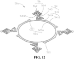
- FIG. 12 is a schematic structural view of a first resilient member 50a provided in another implementation of the disclosure.
- the first resilient member 50a in the another implementation of the disclosure is similar to the first resilient member 50 in one of the above implementations in structure, except that a first connection ring 52a of the first resilient member 50a has a closed-loop structure.
- the first connection ring 52a includes a connection branch 525a that is annular and fixing portions 521 arranged around the connection branch 525a, and the first positioning portion 54 is connected to the fixing portion 521.
- connection branch 525a a is annular
- four fixing portions 521 are disposed at an outer periphery of the connection branch 525a and are evenly arranged at intervals in a circumferential direction of the connection branch 525a.
- Each fixing portion 521 is connected to the first positioning portion 54, and the first positioning portion 54 is connected to the second positioning portion 56.
- the first resilient member 50a has the same assembly relationship and function as the first resilient member 50, which are not described in detail herein.
- FIG. 13 is a schematic exploded perspective structural view of a voice coil motor 110b provided in another implementation of the disclosure.
- the voice coil motor 100b in the another implementation of the disclosure is similar to the voice coil motor 100 in one of the above implementations in structure, except that the second positioning portion 56 of the first resilient member 50 in one of the above implementations is absent in the first resilient member 50b of the voice coil motor 100b, and instead, a magnetic attraction between the frame 30 and the base 80 serves as a positioning mechanism between the frame 30 and the base 80, that is, the magnetic attraction between the frame 30 and the base 80 replaces the second positioning portion 56 of the first resilient member 50.
- the first resilient member 50b only includes the first connection ring 52 and the first positioning portion 54 connected to the outer periphery of the first connection ring 52, the fixing portion 521 of the first connection ring 52 is connected to the carrier 42, and the first positioning sheet 543 is connected to the frame 30.
- the positioning mechanism is disposed on the base 80 and corresponds to the magnetic attraction member 88 of the magnetic member 32, and the magnetic member 32 and the magnetic attraction member 88 cooperate to position the frame 30 to the base 80.
- the base 80 is provided with at least one magnetic attraction member 88 corresponding to each magnetic member 32, and the magnetic member 32 and the magnetic attraction member 88 are attracted to each other, so that the frame 30 and the coil assembly 40 accommodated in the frame 30 are positioned on the base 80.
- each magnetic attraction member 88 extends through the planar coil 70 and exceeds the front face of the planar coil 70, and each magnetic member 32 is slidably connected to the planar coil 70 via the sliding pad 60, direct contact between the magnetic member 32 and the planar coil 70 can be avoided, thereby preventing the magnetic member 32 from damaging the planar coil 70 during sliding of the magnetic member 32 relative to the planar coil 70.
- the second positioning portion 56 is absent in the first resilient member 50b, and processes for manufacturing the first resilient member 50b are simplified, thereby further reducing the production cost of the voice coil motor 100b.
- FIG. 14 is a schematic perspective structural view of a camera provided in an implementation of the disclosure.
- the camera includes the voice coil motor 100/100b and a lens module 300.
- the lens module 300 is disposed in the voice coil motor 100/100b.
- the voice coil motor 100/100b is configured to drive the lens module 300 to move.
- a rear end of the lens module 300 passes through an inner cavity of the second connection ring 22 and is connected to the mounting hole 45 of the carrier 42, and a front end of the lens module 300 passes through the through hole 912 of the cover body 90 to be exposed to the outside of the cover body 90.
- the coil assembly 40 is energized so that the first electromagnetic force is generated between the coil assembly 40 and the magnetic member 32, the first electromagnetic force drives the coil assembly 40 to move axially, and the coil assembly 40 drives the lens module 300 to move together, thereby achieving the autofocus function.
- the planar coil 70 is energized so that the second electromagnetic force is generated between the planar coil 70 and the magnetic member 32, the second electromagnetic force drives the frame 30 and drives the coil assembly 40 attached with the lens module 300 to move along the XOY plane, compensating lens shaking and thus achieving the OIS function.
- FIG. 15 is a schematic perspective structural view of an electronic device provided in an implementation of the disclosure.
- the electronic device includes a housing 500, a main board 600 disposed inside the housing 500, a display screen 700 disposed on a front face of the housing 500, and the camera.
- the camera is disposed inside the housing 500, and the camera and the display screen 700 are electrically connected to the main board 600.
- the electronic device is a mobile phone
- the lens module 300 is a front camera on the mobile phone. Since the overall thickness of the voice coil motor is reduced, an inner space of the housing 500 occupied by the voice coil motor is reduced, thereby facilitating arrangement of other electronic elements.
- the lens module 300 may also be a rear camera.
- the electronic device may also be, but is not limited to, any electronic device that needs to be provided with a lens, such as a tablet computer, a display screen, a smart television, an electronic watch, and a smart bracelet.
- a lens such as a tablet computer, a display screen, a smart television, an electronic watch, and a smart bracelet.
Landscapes
- Physics & Mathematics (AREA)
- Engineering & Computer Science (AREA)
- General Physics & Mathematics (AREA)
- Power Engineering (AREA)
- Electromagnetism (AREA)
- Combustion & Propulsion (AREA)
- Chemical & Material Sciences (AREA)
- Optics & Photonics (AREA)
- Microelectronics & Electronic Packaging (AREA)
- Multimedia (AREA)
- Signal Processing (AREA)
- Lens Barrels (AREA)
- Reciprocating, Oscillating Or Vibrating Motors (AREA)
- Adjustment Of Camera Lenses (AREA)
Abstract
Description
- This application claims priority to
Chinese Patent Application No. 202110252510.8, filed March 8, 2021 - The disclosure relates to the field of electric-control apparatuses, and in particular, to a voice coil motor, a camera provided with the voice coil motor, and an electronic device provided with the camera.
- With the rapid development of the mobile phone industry and faster technology innovation, consumers have increasingly stringent requirements for camera functionality of mobile phones, which poses greater challenges to cameras. Currently, motors used in cameras of the mobile phones on the market generally include autofocus (AF) motors and optical image stabilization (OIS) motors. The OIS motors used in high-end mobile phones are further categorized into ball-type motors and shrapnel-suspended-wire type motor motors. The shrapnel-suspended-wire type motor has a liner force-balancing system of structural reaction forces and thus can be controlled by an open-loop linear current, while the ball-type motor has only reaction forces of static/kinetic friction forces of balls and thus a position of a carrier can be determined only by a closed-loop system of a magnetic induction element. Therefore, the shrapnel-suspended-wire type motor has a lower cost than the ball-type motor. Currently, shrapnel-suspended-wire type OIS motors with two-axis closed-loop control are most widely produced on the market. However, the less expensive shrapnel-suspended-wire type motor has a risk of suspended-wire breakage in terms of reliability.
- The disclosure aims to provide a voice coil motor with high-reliability, a camera provided with the voice coil motor, and an electronic device provided with the camera.
- In order to solve the described technical problem, a voice coil motor is provided in the disclosure. The voice coil motor includes a frame, a magnetic member disposed at the frame, a coil assembly received in an inner cavity of the frame, a first resilient member, a planar coil, and a base. The magnetic member is disposed around the coil assembly. The planar coil is disposed on the base. The frame is disposed on the planar coil. The first resilient member includes a first connection ring connected to the coil assembly and a first positioning portion. The coil assembly is connected to the frame via the first positioning portion. The first positioning portion is configured to reset the coil assembly after movement of the coil assembly relative to the frame. A positioning mechanism is disposed between the frame and the base and configured to reset the frame after movement of the frame relative to the base.
- A camera is further provided in the disclosure. The camera includes a voice coil motor and a lens module. The lens module is provided at the voice coil motor. The voice coil motor is configured to drive the lens module to move.
- An electronic device is further provided in the disclosure. The electronic device includes a housing, a main board disposed inside the housing, and the camera. The camera is disposed inside the housing, and the camera is electrically connected to the main board.
- To describe technical solutions in implementations of the disclosure more clearly, the following briefly introduces the accompanying drawings required for describing the implementations. Apparently, the accompanying drawings in the following description only illustrate some implementations of the disclosure. Those of ordinary skill in the art may also obtain other drawings based on these accompanying drawings without creative efforts.
-
FIG. 1 is a schematic perspective structural view of a voice coil motor provided in an implementation of the disclosure. -
FIG. 2 is a schematic exploded perspective structural view of the voice coil motor inFIG. 1 . -
FIG. 3 is a further schematic exploded perspective structural view of the voice coil motor inFIG. 2 . -
FIG. 4 is a schematic perspective structural view of the voice coil motor inFIG. 3 , viewed from another direction. -
FIG. 5 is a schematic enlarged perspective structural view of a first resilient member inFIG. 2 . -
FIG. 6 is a schematic perspective structural view of an autofocus mechanism inFIG. 2 . -
FIG. 7 is a schematic exploded perspective structural view of an optical image stabilization (OIS) mechanism inFIG. 2 . -
FIG. 8 is a schematic partial perspective structural assembly view of the voice coil motor inFIG. 3 . -
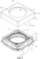
FIG. 9 is a further schematic assembly view of the voice coil motor inFIG. 8 . -
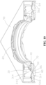
FIG. 10 is a perspective cross-sectional view of the voice coil motor inFIG. 1 , viewed from a direction. -
FIG. 11 is a perspective cross-sectional view of the voice coil motor inFIG. 1 , viewed from another direction. -
FIG. 12 is a schematic structural view of a first resilient member provided in another implementation of the disclosure. -
FIG. 13 is a schematic exploded perspective structural view of a voice coil motor provided in another implementation of the disclosure. -
FIG. 14 is a schematic perspective structural view of a camera provided in an implementation of the disclosure. -
FIG. 15 is a schematic perspective structural view of an electronic device provided in an implementation of the disclosure. - A voice coil motor includes a frame, a magnetic member disposed at the frame, a coil assembly received in an inner cavity of the frame, a first resilient member, a planar coil, and a base. The magnetic member is disposed around the coil assembly. The planar coil is disposed on the base. The frame is disposed on the planar coil. The first resilient member includes a first connection ring connected to the coil assembly and a first positioning portion. The coil assembly is connected to the frame via the first positioning portion. The first positioning portion is configured to reset the coil assembly after movement of the coil assembly relative to the frame. A positioning mechanism is disposed between the frame and the base and configured to reset the frame after movement of the frame relative to the base.
- The coil assembly includes a carrier and a coil wound around the carrier. The first connection ring includes a fixing portion connected to the carrier and a connection portion connected to the coil. The first positioning portion is connected to the fixing portion.
- The first connection ring has an open-loop structure and further includes at least two connection branches. Each of the at least two connection branches extends in a circumferential direction of the first connection ring. The at least two connection branches defines the open-loop structure. Each of both ends of each of the at least two connection branches is provided with a fixing portion, and one of the both ends of each of the at least two connection branches is provided with the connection portion close to the fixing portion.
- The first positioning portion includes a first branch connected to the fixing portion and a first positioning sheet disposed at one end of the first branch away from the fixing portion. The first branch is resilient. The first positioning sheet is connected to the frame.
- The first branch includes an extension section extending in the circumferential direction of the first connection ring and a first branching section connected between the extension section and the first positioning sheet.
- The first branching section extends in a radial direction of the first connection ring.
- The positioning mechanism is a second positioning portion connected to the first positioning portion. The frame is connected to the base via the second positioning portion. The second positioning portion is configured to position the frame to the base.
- A thickness of the first positioning portion is equal to a thickness of the second positioning portion, and the first positioning portion and the second positioning portion are on the same plane in an initial state.
- The second positioning portion includes a second positioning sheet connected to the base and a second branch connected between the first positioning sheet and the second positioning sheet. The second branch has a pre-pressure for driving the frame to move towards the base. The second branch is further configured to reset the frame after movement of the frame.
- The second branch includes a first resilient section connected to the first positioning sheet, a second resilient section connected to the first resilient section, a third resilient section connected to the second resilient section, and a fourth resilient section connected between the third resilient section and the second positioning sheet. The first resilient section, the second resilient section, and the third resilient section surround the first positioning sheet.
- The base is provided with a connection block corresponding to the second positioning sheet. The second positioning sheet is fixedly connected to the connection block. The second positioning sheet is closer to the base than the first positioning sheet.
- The first connection ring has a closed-loop structure. The first connection ring includes a connection branch that is annular and fixing portions arranged around the connection branch. The first positioning portion is connected to the fixing portions.
- The positioning mechanism includes a magnetic attraction member disposed at the base. The magnetic member and the magnetic attraction member cooperate to position the frame to the base.
- The voice coil motor further includes a sliding pad disposed between the planar coil and the frame and/or between the planar coil and the magnetic member. The frame and the magnetic member are slidably disposed on the planar coil via the sliding pad.
- The sliding pad is fixedly connected to the planar coil, and the magnetic member on the frame is in contact with and slidable on the sliding pad.
- The base is provided with a magnetic induction element. The planar coil defines an accommodation groove corresponding to the magnetic induction element, the magnetic induction element is accommodated in the accommodation groove, so that the magnetic induction element corresponds to the magnetic member, and the magnetic induction element is configured to determine a position of the frame.
- The base is provided with a positioning post. The planar coil defines a slot corresponding to the positioning post, and the positioning post is snapped into the slot to position the planar coil to the base.
- The base is provided with a magnetic attraction member corresponding to the magnetic member, and the magnetic member and the magnetic attraction member cooperate to position the frame to the base.
- A camera includes the voice coil motor and a lens module. The lens module is disposed at the voice coil motor, and the voice coil motor is configured to drive the lens module to move.
- An electronic device includes a housing, a main board disposed inside the housing, and the camera. The camera is disposed inside the housing, and the camera is electrically connected to the main board.
- The following clearly and completely describes the technical solutions in the implementations of the disclosure with reference to the accompanying drawings in the implementations of the disclosure. Apparently, the described implementations are merely part rather than all of the implementations of the disclosure. The implementations described herein can be combined with each other appropriately. All other implementations obtained by those of ordinary skill in the art based on the implementations of the disclosure without creative efforts shall fall within the protection scope of the disclosure.
- In addition, the following illustrations of various implementations are provided with reference to the accompanying drawings to illustrate specific implementations that can be implemented in the disclosure. Directional terms such as "up", "down", "front", "back", "left", "right", "inside", "outside", "side", and the like referred to herein which are only for directions with reference to the accompanying drawings. Therefore, the directional terms used herein are intended to better and more clearly illustrate and understand the disclosure, rather than explicitly or implicitly indicate that devices or elements referred to herein must have a certain direction or be configured or operated in a certain direction and therefore cannot be understood as limitation on the disclosure.
- It is noted that, in the illustrations of the disclosure, terms "mount", "couple", "connect", "interconnect", and "disposed" should be understood in a broad sense unless otherwise expressly specified and limited. For example, the terms "mount", "couple", "connect", "interconnect", and "disposed" may refer to fixedly connect, detachably connect, or integrally connect, may refer to mechanically connect, and may refer to a directly connect, indirectly connect through an intermediate medium, or an intercommunicate interiors of two elements. For those of ordinary skill in the art, the specific meanings of the above terms in the disclosure can be understood according to specific situations.
- Referring to
FIGs. 1 to 5 ,FIG. 1 is a schematic perspective structural view of avoice coil motor 100 provided in an implementation of the disclosure,FIG. 2 is a schematic exploded perspective structural view of thevoice coil motor 100 inFIG. 1 ,FIG. 3 is a further schematic exploded perspective structural view of thevoice coil motor 100 inFIG. 2 ,FIG. 4 is a schematic perspective structural view of thevoice coil motor 100 inFIG. 3 , viewed from another direction, andFIG. 5 is an enlarged view of a firstresilient member 50 inFIG. 2 . Thevoice coil motor 100 provided in an implementation of the disclosure includes an autofocus mechanism and an optical image stabilization (OIS) mechanism. The autofocus mechanism includes the firstresilient member 50, a secondresilient member 20, aframe 30, amagnetic member 32 disposed at theframe 30, and acoil assembly 40 movably disposed in an inner cavity of theframe 30. Themagnetic member 32 is fixedly connected to theframe 30 and surrounds thecoil assembly 40. The firstresilient member 50 and the secondresilient member 20 are disposed on a front face and a back face of thecoil assembly 40, respectively. The firstresilient member 50 is connected to thecoil assembly 40, and the secondresilient member 20 is connected to theframe 30. The OIS mechanism includes a slidingpad 60, aplanar coil 70, and abase 80. The slidingpad 60 is disposed on theplanar coil 70. Theplanar coil 70 is disposed on thebase 80. Theframe 30 is disposed on theplanar coil 70. The slidingpad 60 is sandwiched between theframe 30 and theplanar coil 70. A circuit board is disposed in thebase 80. The circuit board is electrically connected to theplanar coil 70, and is provided with a drive chip, an output interface, and the like. The firstresilient member 50 is disposed at thecoil assembly 40 and disposed between theframe 30 and thebase 80. The firstresilient member 50 includes afirst connection ring 52 connected to thecoil assembly 40 and afirst positioning portion 54 connected to thefirst connection ring 52. Thecoil assembly 40 is connected to theframe 30 via thefirst positioning portion 54. Thefirst positioning portion 54 is configured to reset thecoil assembly 40 after movement of thecoil assembly 40 relative to theframe 30. A positioning mechanism is disposed between theframe 30 and thecoil assembly 40 and configured to reset theframe 30 after movement of theframe 30 relative to thebase 80. In the implementations, the firstresilient member 50 further includes asecond positioning portion 56 connected to thefirst positioning portion 54. The positioning mechanism is thesecond positioning portion 56 disposed between theframe 30 and thebase 80. That is, theframe 30 is connected to thebase 80 via thesecond positioning portion 56, and thesecond positioning portion 56 is configured to reset theframe 30 after movement of theframe 30 relative to thebase 80. - During operation of the
voice coil motor 100, thecoil assembly 40 is energized so that a first electromagnetic force is generated between thecoil assembly 40 and themagnetic member 32 to drive thecoil assembly 40 attached with a lens to move in an axial direction, achieving an autofocus function; theplanar coil 70 is energized so that a second electromagnetic force is generated between theplanar coil 70 and themagnetic member 32 to drive theframe 30 and thecoil assembly 40 attached with the lens to move in thevoice coil motor 100 along a XOY plane, compensating lens shaking and thus achieving OIS function. The axial direction refers to a direction parallel to an axis of the lens, that is, the axial direction is a Z-axis direction illustrated inFIGs. 1 to 3 . - The
voice coil motor 100 provided in the disclosure includes the firstresilient member 50, and thefirst connection ring 52 of the firstresilient member 50 is connected to thecoil assembly 40. Thefirst positioning portion 54 is connected between theframe 30 and thecoil assembly 40. Thefirst positioning portion 54 is configured to reset thecoil assembly 40 after movement of thecoil assembly 40 relative to theframe 30. Thesecond positioning portion 56 is connected between theframe 30 and thebase 80. Thesecond positioning portion 56 is configured to reset theframe 30 and thecoil assembly 40 after movement of theframe 30 and thecoil assembly 40 relative to thebase 80. Because the firstresilient member 50 is firmly connected to thecoil assembly 40, theframe 30, and thebase 80, the reliability is high, and compared with a suspended-wire type motor in the related art, a risk of suspended-wire breakage can be avoided. - The
coil assembly 40 includes acarrier 42 and acoil 44 wound around thecarrier 42. Thecarrier 42 is a wire frame, and the wire frame is fixed to thecoil 44 in an integrated winding manner. Thecarrier 42 defines a mountinghole 45 that axially extends through a front face and a back face of thecarrier 42. The mountinghole 45 is used for connection of the lens. The front face of thecarrier 42 refers to a face of thecarrier 42 facing the same direction as a light-incident hole of the lens, and the back face of thecarrier 42 refers to a face of thecarrier 42 facing away from the light-incident hole of the lens. Thecarrier 42 is provided withmultiple positioning posts 421 and multiplefirst impact bosses 423 on the front face of thecarrier 42. A length of the positioning posts 421 in the axial direction is less than a length of thefirst impact boss 423 in the axial direction. The positioning posts 421 are used for connection of the secondresilient member 20. Thefirst impact bosses 423 are used for preventing the lens attached to thecarrier 42 from being directly impacted, thereby protecting the lens. Apositioning ring 422 is disposed on the back face of thecarrier 42 and surrounds the mountinghole 45. Thecarrier 42 definesmultiple connection grooves 424 and is provided with multiplesecond impact bosses 425, and themultiple connection grooves 424 and the multiplesecond impact bosses 425 are on the back face of thecarrier 42 and arranged around thepositioning ring 422. Theconnection grooves 424 is used for connection of the firstresilient member 50. Thesecond impact bosses 425 are used for preventing the lens attached to thecarrier 42 from being directly impacted, thereby protecting the lens. Thecarrier 42 is provided with two coil-connection ends 427 at an outer periphery of thecarrier 42. Thefirst connection ring 52 of the firstresilient member 50 is electrically connected to the coil-connection ends 427. In the implementations, thecarrier 42 is provided with fourpositioning posts 421 and fourfirst impact bosses 423 on the front face of thecarrier 42, the fourpositioning posts 421 are evenly arranged at intervals in a circumferential direction of thecarrier 42, and the fourfirst impact bosses 423 are arranged in a circle in the circumferential direction of thecarrier 42. Thecarrier 42 is provided with fourconnection grooves 424 and foursecond impact bosses 425 on the back face of thecarrier 42. The fourconnection grooves 424 are evenly arranged at intervals in the circumferential direction of thecarrier 42, and the foursecond impact bosses 425 are arranged in a circle in the circumferential direction of thecarrier 42. The foursecond impact bosses 425 respectively correspond to the fourfirst impact bosses 423 in the axial direction. - Referring to
FIGs. 2 to 4 andFIG. 6, FIG. 6 is a schematic perspective structural view of the autofocus mechanism inFIG. 2 . The secondresilient member 20 is a resilient sheet. The resilient sheet includes asecond connection ring 22 surrounding thecoil assembly 40 andmultiple positioning portions 24 connected to an outer periphery of thesecond connection ring 22. Each positioningportion 24 is connected between theframe 30 and thecarrier 42. Specifically, thesecond connection ring 22 is a closed-ring formed by a thin strip. Multiple fixingportions 221 are disposed at the outer periphery of thesecond connection ring 22. Themultiple positioning portions 24 are connected to the multiple fixingportions 221, respectively. In the implementations, an inner diameter of thesecond connection ring 22 is slightly larger than a diameter of the mountinghole 45 of thecarrier 42, and an outer diameter of thesecond connection ring 22 is smaller than an outer diameter of thecarrier 42. The multiple fixingportions 221 are implemented as four fixingportions 221 evenly arranged at intervals in a circumferential direction of thesecond connection ring 22. Themultiple positioning portions 24 are implemented as fourpositioning portions 24, and the fourpositioning portions 24 are respectively connected to the four fixingsections 221 and evenly arranged at intervals in the circumferential direction of thesecond connection ring 22. Each fixingportion 221 is a lug connected to thesecond connection ring 22. Each fixingportion 221 defines a fixinghole 223 extending axially. The positioningportion 24 includes aconnection branch 241 that is resilient and connected to thefixing section 221, and apositioning sheet 243 disposed at an end of theconnection branch 241 away from the fixingsection 221. Thepositioning sheet 243 is connected to theframe 30. Theconnection branch 241 is in a curve shape at a position close to thepositioning sheet 243. Thepositioning sheet 243 defines apositioning hole 245 extending axially. - The
frame 30 includesmultiple side walls 31. Theside walls 31 are connected end to end to surround a space to define anaccommodation space 33. Theaccommodation space 33 is used for accommodating thecoil assembly 40. The multiplemagnetic members 32 are disposed on an inner periphery of theframe 30, so that the multiplemagnetic members 32 are arranged in a circle in a circumferential direction of thecoil 44. An inner side face of eachside wall 31 defines apositioning groove 312, and themagnetic member 32 is fixedly connected in thepositioning groove 312. Specifically, themagnetic member 32 may be connected to theframe 30 by adhesive bonding, snap-fitting, or thermal fusion. In the implementations, theframe 30 is rectangular and includes fourside walls 31. The fourside walls 31 are connected end to end to surround a space to define therectangular accommodation space 33. The inner side face of eachside wall 31 defines therectangular positioning groove 312. The multiplemagnetic members 32 are four elongated magnetic bodies fixedly connected to the fourpositioning grooves 312 of theside walls 31, respectively, so that the four magnetic bodies surround theaccommodation space 33. - The
frame 30 is provided with multiple connection posts 314 on a front face of theframe 30, and themultiple connection posts 314 are connected to thepositioning sheets 243 of the secondresilient member 20. In the implementations, afirst avoidance groove 315 is defined on a front face of an intersection of each twoadjacent side walls 31, theconnection post 314 protrudes from a bottom face of thefirst avoidance groove 315, and thefirst avoidance groove 315 is in communication with theaccommodation space 33 of theframe 30. Preferably, a length of theconnection post 314 is smaller than a depth of a correspondingfirst avoidance groove 315, so that a front face of the secondresilient member 20 connected to theframe 30 does not exceed the front face of theframe 30, thereby reducing an overall thickness of thevoice coil motor 100. Theframe 30 is provided with multiple fixingposts 316 on a back face of theframe 30, and the fixingposts 316 are connected to thefirst positioning portions 54 of the firstresilient member 50. In the implementations, asecond avoidance groove 317 is formed on a back face of the intersection of each twoadjacent side walls 31, the fixingpost 316 protrudes from a bottom face of thesecond avoidance groove 317, and thesecond avoidance groove 317 is in communication with theaccommodation space 33 of theframe 30. Preferably, a length of the fixingpost 316 is less than a depth of a correspondingsecond avoidance groove 317, so that a back face of the firstresilient member 50 connected to theframe 30 does not exceed the back face of theframe 30, thereby reducing the overall thickness of thevoice coil motor 100. - Referring to
FIGs. 2 to 5 , thefirst connection ring 52 includes a fixingportion 521 connected to thecarrier 42 and aconnection portion 523 connected to the coil-connection end 427. The fixingportion 521 is configured to fix thefirst connection ring 52 to thecarrier 42, the fixingportion 521 is further connected to thefirst positioning portion 54, and theconnection portion 523 is configured to be electrically connected to thecoil 44. In the implementations, thefirst connection ring 52 has an open-loop structure, that is, thefirst connection ring 52 is not a closed-ring structure. Specifically, thefirst connection ring 52 further includes at least twoconnection branches 525, eachconnection branch 525 is in an arc-shape and extends in a circumferential direction of thefirst connection ring 52, and the at least twoconnection branches 525 form a ring with a gap. Each of both ends of eachconnection branch 525 is provided with a fixingportion 521, and the fixingportion 521 is connected to thefirst positioning portion 54, so that theconnection branch 525 can be uniformly stressed. One of both ends of eachconnection branch 525 is provided with theconnection portion 523 close to acorresponding fixing portion 521. Preferably, the fixingportion 521 is a lug protruding from an outer periphery of theconnection branch 525, and the lug defines a throughhole 5210. One end of theconnection portion 523 away from theconnection branch 525 is provided with a connection branch connected to the coil-connection end 427 of thecarrier 42. - The
first positioning portion 54 includes afirst branch 541 connected to the fixingportion 521 and afirst positioning sheet 543 disposed at one end of thefirst branch 541 away from the fixingportion 521, thefirst branch 541 is resilient, and thefirst positioning sheet 543 is connected to theframe 30. Preferably, thefirst positioning sheet 543 defines aconnection hole 5432. Thefirst branch 541 is made of a resilient material, that is, thefirst branch 541 is configured to reset thecoil assembly 40 after thecoil assembly 40 moves relative to theframe 30. Specifically, when thecoil 44 is energized, the first electromagnetic force is generated between thecoil 44 and themagnetic member 32, the first electromagnetic force drives thecoil assembly 40 to move in the axial direction, and thefirst branch 541 resets thecoil assembly 40 after thecoil assembly 40 moves relative to theframe 30, so that an autofocus function of the lens attached to thecoil assembly 40 can be achieved. In the implementations, thefirst positioning portions 54 is implemented as fourfirst positioning portions 54, and the fourfirst positioning portions 54 are connected to the four fixingportions 521 of thefirst connection ring 52, respectively. The fourfirst positioning portions 54 are arranged at intervals in the circumferential direction of thefirst connection ring 52, and thefirst positioning sheet 543 of eachfirst positioning portion 54 is connected to theframe 30. Specifically, thefirst branch 541 includes anextension section 5412 extending in the circumferential direction of thefirst connection ring 52 and a first branchingsection 5414 connected between theextension section 5412 and thefirst positioning sheet 543, and the first branchingsection 5414 extends in a radial direction of thefirst connection ring 52. Preferably, the first branchingsection 5414 curves in a wave shape. - In the implementations, a thickness of the
first connection ring 52 is equal to a thickness of thefirst positioning portion 54, that is, in an initial state, thefirst connection ring 52 and thefirst positioning portion 54 are on the same plane. - The
second positioning portion 56 is connected between thefirst positioning portion 54 and thebase 80, and thesecond positioning portion 56 is configured to position theframe 30 to thebase 80. Specifically, thesecond positioning portion 56 is connected between thefirst positioning sheet 543 and thebase 80. In the implementations, thesecond positioning portion 56 includes asecond positioning sheet 562 connected to thebase 80 and asecond branch 564 connected between thefirst positioning sheet 543 and thesecond positioning sheet 562. Thesecond branch 564 is made of a resilient material so that thesecond branch 564 has a pre-pressure that can drive theframe 30 to move towards thebase 80, and the second branch 546 is further configured to reset theframe 30 after theframe 30 moves. Preferably, thefirst positioning sheet 543 and a correspondingsecond positioning sheet 562 are arranged in the radial direction of thefirst connection ring 52, and thesecond positioning sheet 562 is farther away from thefirst connection ring 52 than thefirst positioning sheet 562. - The
second branch 564 bends from thefirst positioning sheet 543 toward a Y-direction and a X-direction to be connected to thesecond positioning sheet 562. Specifically, thesecond branch 564 includes a firstresilient section 5641 connected to thefirst positioning sheet 543, a secondresilient section 5643 connected to the firstresilient section 5641, and a thirdresilient section 5645 connected to the secondresilient section 5643, and a fourthresilient section 5646 connected between the thirdresilient section 5645 and thesecond positioning sheet 562. The firstresilient section 5641, the secondresilient section 5643, and the thirdresilient section 5645 surround thefirst positioning sheet 543. Specifically, the firstresilient section 5641 first bends from a side of thefirst positioning sheet 543 facing thefirst branch 541 towards theextension section 5412, and then further bends towards thefirst positioning sheet 543. The secondresilient section 5643 and the thirdresilient section 5645 each are in a substantially wavy shape. An extending direction of the secondresilient section 5643 is substantially perpendicular to an extending direction of the thirdresilient section 5645. The secondresilient section 5643 is connected between the firstresilient section 5641 and the thirdresilient section 5645. The fourthresilient section 5646 is in a straight-strip shape. The fourthresilient section 5646 is connected between thesecond positioning sheet 562 and an end of the thirdresilient section 5645 away from the secondresilient section 5643. - In the implementations, a thickness of the
first positioning portion 54 is equal to a thickness of thesecond positioning portion 56, that is, in the initial state, thefirst positioning portion 54 and thesecond positioning portion 56 are on the same plane. Specifically, eachfirst connection ring 52 is integrally formed on the same plane with thefirst positioning portion 54 and thesecond positioning portion 56 on thefirst connection ring 52. - Referring to
FIGs. 2 to 4 andFIG. 7, FIG. 7 is a schematic exploded perspective structural view of the OIS mechanism inFIG. 2 . The slidingpad 60 is made of a wear-resistant material, that is, the slidingpad 60 is made of a material having a low friction coefficient. For example, the slidingpad 60 may be made of, but is not limited to, polyoxymethylene resin. In the implementations, at least one slidingpad 60 is disposed between eachmagnetic member 32 and theplanar coil 70, that is, at least one slidingpad 60 is disposed between each of the fourmagnetic members 32 and theplanar coil 70, and themagnetic member 32 is attached to theplanar coil 70 via the slidingpad 60. With the slidingpad 60, direct contact between themagnetic member 32 and theplanar coil 70 can be avoided, thereby preventing themagnetic member 32 from damaging theplanar coil 70 during sliding of themagnetic member 32 relative to theplanar coil 70. Specifically, the slidingpad 60 is fixedly connected to theplanar coil 70, and themagnetic member 32 is in contact with and slidable on the slidingpad 60. In the implementations, the slidingpad 60 is fixedly adhered to theplanar coil 70, that is, the slidingpad 60 is fixedly connected to a front face of theplanar coil 70 via an adhesive. - In other implementations, the sliding
pad 60 may also be disposed between theframe 30 and theplanar coil 70, the slidingpad 60 is fixedly connected to theplanar coil 70, and theframe 30 is in contact with and slidable on the slidingpad 60. The slidingpad 60 can prevent direct contact between theframe 30 and theplanar coil 70 and direct contact between themagnetic member 32 and theplanar coil 70. - In other implementations, the sliding
pad 60 may also be fixed to theplanar coil 70 by snap-fitting or heat insulation. - The
planar coil 70 includes asupport frame 71 and a coil (not illustrated) disposed in thesupport frame 71. Thesupport frame 71 defines a throughhole 72 at the middle of thesupport frame 71, the throughhole 72 extends axially, and the coil is wound around the throughhole 72. The slidingpads 60 are fixed on the front face of theplanar coil 70 and arranged in a circumferential direction of the throughhole 72. In the implementations, thesupport frame 71 is a rectangular plate. Thesupport frame 71 definesslots 74 at corners of thesupport frame 71, and thesupport frame 71 is fixedly connected to thebase 80 via theslots 74. Thesupport frame 71 definesaccommodation grooves 75 at two adjacent sides of a front face of thesupport frame 71, respectively, and each of theaccommodation grooves 75 extends through the front face and a back face of thesupport frame 71. - The
base 80 includes abase body 81 and the circuit board disposed in thebase body 81. Thebase body 81 defines anaccommodation hole 82 at the middle of a front face of thebase body 81. Theaccommodation hole 82 is used for accommodating a sensor or a drive chip, etc. Awelding portion 83 is disposed on an inner periphery of theaccommodation hole 82 and electrically connected to the circuit board. Thewelding portion 83 is configured to be electrically connected to the coil of theplanar coil 70. Thebase 80 is provided with aconnection block 84 corresponding to thesecond positioning sheet 562 of the firstresilient member 50, and thesecond positioning sheet 562 is fixedly connected to theconnection block 84. In the implementations, thebase body 81 is a rectangular body. The connection blocks 84 protrude from four corners of the front face of thebase body 81, respectively, and foursecond positioning sheets 562 of the firstresilient member 50 are connected to the four connection blocks 84, respectively. Thebase 80 is provided withpositioning posts 86, and the positioning posts 86 are respectively snapped into theslots 74 of theplanar coil 70 to position theplanar coil 70 to thebase 80. In the implementations, fourpositioning posts 86 are disposed on the front face of thebase body 81 and arranged around the accommodation holes 82. - The
base 80 is provided with amagnetic induction element 87 electrically connected to the circuit board, and theaccommodation groove 75 of theplanar coil 70 corresponds to themagnetic induction element 87. Theplanar coil 70 is disposed on thebase 80, and themagnetic induction element 87 is accommodated in theaccommodation groove 75, so that themagnetic induction element 87 corresponds to themagnetic member 32, and themagnetic induction element 87 is configured to determine a position of theframe 30. In the implementations, themagnetic induction elements 87 are soldered to the circuit board of thebase 80. Specifically, the circuit board of thebase 80 is provided with twosolder pads 88 respectively corresponding to two adjacentmagnetic members 32, and the twomagnetic induction elements 87 are respectively soldered to the twosolder pads 88 through surface-mount technology (SMT). - The
base 80 is provided withmultiple pins 801 electrically connected to the circuit board. Themultiple pins 801 are soldered to a main board of an electronic device, so that thevoice coil motor 100 can be electrically connected to the main board. In the implementations, a row of thepins 801 is disposed on each of two opposite sides of thebase 80. Multiple connection blocks 803 are disposed on an outer periphery of thebase 80. Specifically, thebase 80 is provided withconnection blocks 803 that protrude from each outer sidewall of thebase 80 and are spaced from each other. - The
voice coil motor 100 further includes acover body 90. Thecover body 90 includes acover plate 91 andside plates 93 surrounding thecover plate 91. Thecover plate 91 and theside plates 93 surround a space to define anaccommodation space 94. Thecover plate 91 defines a throughhole 912 at the middle of thecover plate 91. The lens extends through the throughhole 912, and theside plates 93 are fixedly connected to thebase 80. In the implementations, thecover plate 91 is a rectangular plate, four edges of the rectangular plate are respectively connected to theside plates 93, each of theside plates 93 extends in the axial direction, and two positioningslots 932 are defined at one side of each of theside plates 93 away from thecover plate 91. - Referring to
FIGs. 1 to 4 andFIGs. 8 to 11 , during assembly of thevoice coil motor 100, the multiplemagnetic members 32 are respectively fixed in themultiple positioning grooves 312 of theframe 30; thecoil assembly 40 is received in theaccommodation space 33 of theframe 30, and the secondresilient member 20 is disposed on the front face of theframe 30 and the front face of thecoil assembly 40, so that themultiple positioning posts 421 of thecarrier 42 are respectively snapped into the multiple fixingholes 223 of the secondresilient member 20, thesecond connection ring 22 is fixedly connected to thecarrier 42, and thesecond connection ring 22 surrounds the mountinghole 45 of thecarrier 42; thepositioning sheets 243 of the secondresilient member 20 are respectively received in thefirst avoidance grooves 315 of theframe 30, themultiple connection posts 314 are respectively snapped into the positioning holes 245 of thepositioning sheets 243, and at this point, each positioningportion 24 is resiliently connected between thecoil assembly 40 and theframe 30. In other implementations, the fixingportion 221 may also be fixedly connected to thecarrier frame 42 by adhesive bonding, snap-fitting, or the like, and thepositioning sheet 243 may also be fixedly connected to theframe 30 by adhesive bonding, snap-fitting, or the like. - The first
resilient member 50 is connected between thecoil assembly 40 and theframe 30. Specifically, thefirst connection ring 52 is disposed at thepositioning ring 422 on the back face of thecarrier 42, so that the multiple fixingportions 521 of thefirst connection ring 52 face themultiple connection grooves 424, respectively. Each fixingportion 521 is connected to acorresponding connection groove 424 via an adhesive, that is, the adhesive is accommodated in theconnection groove 424 and the throughhole 5210 of the fixingportion 521, so that the fixingportion 521 is firmly connected to thecarrier 42. The multiplefirst positioning sheets 543 are respectively disposed in the multiplesecond avoidance grooves 317, and the multiple fixingposts 316 are respectively snapped into themultiple connection holes 5432, so that thefirst positioning portion 54 is resiliently connected between thecoil assembly 40 and theframe 30. In other implementations, the fixingportion 521 may also be connected to thecoil assembly 40 by snap-fitting, screwing, or the like. Thefirst positioning sheet 543 can be connected to theframe 30 by adhesive bonding, screwing, or the like. - The
magnetic induction element 87 is soldered to thesolder pad 88 of thebase 80, and theplanar coil 70 is disposed on the front face of thebase 80, so that themultiple positioning posts 86 of the base 80 are respectively snapped into themultiple slots 74 of theplanar coil 70. At this point, theplanar coil 70 is fixedly connected to thebase 80, and themagnetic induction element 87 is accommodated in acorresponding accommodation groove 75. In other implementations, theplanar coil 70 may also be fixed to thebase 80 by screwing or adhesive bonding. Theframe 30 accommodating thecoil assembly 40 is disposed on theplanar coil 70, so that the fourmagnetic members 32 of theframe 30 are respectively supported by the four slidingpads 60 of theplanar coil 70, and the foursecond positioning sheets 562 respectively face the four connection blocks 84 of thebase 80. Eachsecond positioning portion 56 is stretched towards thebase 80, so that eachsecond positioning sheet 562 is attached to acorresponding connection block 84, and then eachsecond positioning sheet 562 is connected to acorresponding connection block 84 by welding, so that thesecond positioning portion 56 is resiliently connected between theframe 30 and thebase 80. At this point, there is a height difference between thefirst positioning sheet 543 and a correspondingsecond positioning sheet 562, that is, thesecond branch 564 between thefirst positioning sheet 543 and thesecond positioning sheet 562 is resiliently deformed to have the pre-pressure for driving theframe 30 to move towards thebase 80, so that theframe 30 is positioned on thebase 80. Specifically, one end of the second branch 546 away from thefirst positioning sheet 543 bends toward thebase 80. Thecover body 90 covers theframe 30 so that the multiple connection blocks 803 of the base 80 are respectively snapped into themultiple positioning slots 932 of thecover body 90. In the implementations, thesecond positioning sheet 562 is closer to the base 80 than thefirst positioning sheet 543. - In other implementations, a height difference between the
second positioning sheet 562 of the firstresilient member 50 and a correspondingfirst positioning sheet 543 is preset, that is, thesecond positioning sheet 562 is farther away from thefirst connection ring 52 than thefirst positioning sheet 543. Specifically, one end of thesecond branch 564 away from thefirst positioning sheet 543 bends away from thefirst connection ring 52. When the firstresilient member 50 is assembled on thebase 80 and theframe 30, thefirst positioning sheet 543 and thesecond positioning sheet 562 are on the same plane, and at this point, thesecond branch 564 between thefirst positioning sheet 543 and thesecond positioning sheet 562 is resiliently deformed to have the pre-pressure for driving theframe 30 to move towards thebase 80, so that theframe 30 is positioned on thebase 80. - When the
coil 44 is energized, the first electromagnetic force is generated between thecoil 44 on thecoil assembly 40 and themagnetic member 32 on theframe 30. The first electromagnetic force pushes thecoil assembly 40 to move in the axial direction, that is, the first electromagnetic force pushes thecoil assembly 40 to move up/down in the axial direction in theaccommodation space 33 of theframe 30, so that an autofocus function of the lens attached to thecarrier 42 can be achieved. During movement of thecoil assembly 40, the positioningportion 24 of the secondresilient member 20 and thefirst positioning portion 54 of the firstresilient member 50 are resiliently deformed, and thepositioning portion 24 of the secondresilient member 20 and thefirst positioning portion 54 of the firstresilient member 50 can restore to reset thecoil assembly 40 after the first electromagnetic force is removed. Meanwhile, the second electromagnetic force is generated between themagnetic member 32 of theframe 30 and theplanar coil 70, the second electromagnetic force pushes theframe 30 and drives thecoil assembly 40 attached with the lens to move along the XOY plane in theaccommodation space 94 of thecover body 90 to compensate lens shaking, and themagnetic member 32 slides on a corresponding slidingpad 60, achieving the OIS function. During movement of theframe 30, thesecond branch 564 of thesecond positioning portion 56 is resiliently deformed, and thesecond branch 564 can restore to reset the frame and thecoil assembly 40 together after the second electromagnetic force is removed. - Since the
second positioning portion 56 has a resilient force for pre-pressing theframe 30 onto theplanar coil 70, theframe 30 has a tendency to approach theplate coil 70. The slidingpad 60 is provided between themagnetic member 32 and theplate coil 70, a small friction force is achieved with the slidingpad 60, and thefirst branch 541 and thesecond branch 564 have anti-actuation forces to reset thecoil assembly 40 and theframe 30 after movement of thecoil assembly 40 and theframe 30. - In the
voice coil motor 100 of the disclosure, the firstresilient member 50 is adopted, and the firstresilient member 50 is connected to thecoil assembly 40, theframe 30, and thebase 80. Thus, thevoice coil motor 100 has a higher reliability than an existing voice coil motor on the market. In addition, a suspended-wire system of the existing voice coil motor on the market is replaced with the firstresilient member 50 and the slidingpad 60, and thesecond branch 564 pre-presses theframe 30 onto theplanar coil 70, thereby improving the reliability of thevoice coil motor 100, and avoiding a reliability risk of a suspension type system of an existing suspended-wire OIS motor on the market. Secondly, the slidingpad 60 is relatively thin, so that the thickness of the slidingpad 60 is less than a diameter of a ball in a ball-type OIS motor in the related art. Therefore, a thickness of thevoice coil motor 100 in the axial direction is reduced, so that the overall thickness of thevoice coil motor 100 is reduced, thereby reducing an inner space of the electronic device occupied by thevoice coil motor 100 and facilitating arrangement of other electronic elements in the electronic device. Furthermore, the firstresilient member 50 is designed to have an open-loop structure with a relatively low cost, and both thefirst branch 541 and thesecond branch 564 have resilient curved configurations, that is, both thefirst branch 541 and thesecond branch 564 can be resiliently deformed and reset. As a result, a low-cost open-loop solution can be employed for thevoice coil motor 100. Moreover, during production of thevoice coil motor 100, processes can be simplified, automation can be enhanced, the production efficiency can be improved, and the cost can be reduced. - Referring to
FIG. 5 andFIG. 12, FIG. 12 is a schematic structural view of a firstresilient member 50a provided in another implementation of the disclosure. The firstresilient member 50a in the another implementation of the disclosure is similar to the firstresilient member 50 in one of the above implementations in structure, except that afirst connection ring 52a of the firstresilient member 50a has a closed-loop structure. Specifically, thefirst connection ring 52a includes aconnection branch 525a that is annular and fixingportions 521 arranged around theconnection branch 525a, and thefirst positioning portion 54 is connected to the fixingportion 521. In the implementations, theconnection branch 525a a is annular, four fixingportions 521 are disposed at an outer periphery of theconnection branch 525a and are evenly arranged at intervals in a circumferential direction of theconnection branch 525a. Each fixingportion 521 is connected to thefirst positioning portion 54, and thefirst positioning portion 54 is connected to thesecond positioning portion 56. The firstresilient member 50a has the same assembly relationship and function as the firstresilient member 50, which are not described in detail herein. - Referring to
FIG. 5 andFIG. 13, FIG. 13 is a schematic exploded perspective structural view of a voice coil motor 110b provided in another implementation of the disclosure. Thevoice coil motor 100b in the another implementation of the disclosure is similar to thevoice coil motor 100 in one of the above implementations in structure, except that thesecond positioning portion 56 of the firstresilient member 50 in one of the above implementations is absent in the firstresilient member 50b of thevoice coil motor 100b, and instead, a magnetic attraction between theframe 30 and thebase 80 serves as a positioning mechanism between theframe 30 and thebase 80, that is, the magnetic attraction between theframe 30 and thebase 80 replaces thesecond positioning portion 56 of the firstresilient member 50. Specifically, the firstresilient member 50b only includes thefirst connection ring 52 and thefirst positioning portion 54 connected to the outer periphery of thefirst connection ring 52, the fixingportion 521 of thefirst connection ring 52 is connected to thecarrier 42, and thefirst positioning sheet 543 is connected to theframe 30. In the implementations, the positioning mechanism is disposed on thebase 80 and corresponds to themagnetic attraction member 88 of themagnetic member 32, and themagnetic member 32 and themagnetic attraction member 88 cooperate to position theframe 30 to thebase 80. Specifically, thebase 80 is provided with at least onemagnetic attraction member 88 corresponding to eachmagnetic member 32, and themagnetic member 32 and themagnetic attraction member 88 are attracted to each other, so that theframe 30 and thecoil assembly 40 accommodated in theframe 30 are positioned on thebase 80. In the implementations, eachmagnetic attraction member 88 extends through theplanar coil 70 and exceeds the front face of theplanar coil 70, and eachmagnetic member 32 is slidably connected to theplanar coil 70 via the slidingpad 60, direct contact between themagnetic member 32 and theplanar coil 70 can be avoided, thereby preventing themagnetic member 32 from damaging theplanar coil 70 during sliding of themagnetic member 32 relative to theplanar coil 70. Thesecond positioning portion 56 is absent in the firstresilient member 50b, and processes for manufacturing the firstresilient member 50b are simplified, thereby further reducing the production cost of thevoice coil motor 100b. - Referring to
FIG. 3 andFIG. 14, FIG. 14 is a schematic perspective structural view of a camera provided in an implementation of the disclosure. The camera includes thevoice coil motor 100/100b and alens module 300. Thelens module 300 is disposed in thevoice coil motor 100/100b. Thevoice coil motor 100/100b is configured to drive thelens module 300 to move. Specifically, a rear end of thelens module 300 passes through an inner cavity of thesecond connection ring 22 and is connected to the mountinghole 45 of thecarrier 42, and a front end of thelens module 300 passes through the throughhole 912 of thecover body 90 to be exposed to the outside of thecover body 90. During usage of the camera, thecoil assembly 40 is energized so that the first electromagnetic force is generated between thecoil assembly 40 and themagnetic member 32, the first electromagnetic force drives thecoil assembly 40 to move axially, and thecoil assembly 40 drives thelens module 300 to move together, thereby achieving the autofocus function. Theplanar coil 70 is energized so that the second electromagnetic force is generated between theplanar coil 70 and themagnetic member 32, the second electromagnetic force drives theframe 30 and drives thecoil assembly 40 attached with thelens module 300 to move along the XOY plane, compensating lens shaking and thus achieving the OIS function. - Referring to
FIG. 15, FIG. 15 is a schematic perspective structural view of an electronic device provided in an implementation of the disclosure. The electronic device includes ahousing 500, amain board 600 disposed inside thehousing 500, adisplay screen 700 disposed on a front face of thehousing 500, and the camera. The camera is disposed inside thehousing 500, and the camera and thedisplay screen 700 are electrically connected to themain board 600. In the implementations, the electronic device is a mobile phone, and thelens module 300 is a front camera on the mobile phone. Since the overall thickness of the voice coil motor is reduced, an inner space of thehousing 500 occupied by the voice coil motor is reduced, thereby facilitating arrangement of other electronic elements. In other implementations, thelens module 300 may also be a rear camera. - In other implementations, the electronic device may also be, but is not limited to, any electronic device that needs to be provided with a lens, such as a tablet computer, a display screen, a smart television, an electronic watch, and a smart bracelet.
- The above are only some implementations of the disclosure. It is noted that, a person skilled in the art may make further improvements and modifications without departing from the principle of the disclosure, and these improvements and modifications shall also belong to the scope of protection of the disclosure.
Claims (20)
- A voice coil motor, comprising a frame, a magnetic member disposed at the frame, a coil assembly received in an inner cavity of the frame, a first resilient member, a planar coil, and a base, wherein the magnetic member is disposed around the coil assembly, the planar coil is disposed on the base, the frame is disposed on the planar coil, and the first resilient member comprises a first connection ring connected to the coil assembly and a first positioning portion, wherein the coil assembly is connected to the frame via the first positioning portion, the first positioning portion is configured to reset the coil assembly after movement of the coil assembly relative to the frame, and a positioning mechanism is disposed between the frame and the base and configured to reset the frame after movement of the frame relative to the base.
- The voice coil motor of claim 1, wherein the coil assembly comprises a carrier and a coil wound around the carrier, the first connection ring comprises a fixing portion connected to the carrier and a connection portion connected to the coil, and the first positioning portion is connected to the fixing portion.
- The voice coil motor of claim 2, wherein the first connection ring has an open-loop structure and further comprises at least two connection branches, wherein each of the at least two connection branches extends in a circumferential direction of the first connection ring, and the at least two connection branches define the open-loop structure, each of both ends of each of the at least two connection branches is provided with the fixing portion, and one of the both ends of each of the at least two connection branches is provided with the connection portion close to the fixing portion.
- The voice coil motor of claim 2 or 3, wherein the first positioning portion comprises a first branch connected to the fixing portion and a first positioning sheet disposed at one end of the first branch away from the fixing portion, the first branch is resilient, and the first positioning sheet is connected to the frame.
- The voice coil motor of claim 4, wherein the first branch comprises an extension section extending in a circumferential direction of the first connection ring and a first branching section connected between the extension section and the first positioning sheet.
- The voice coil motor of claim 5, wherein the first branching section extends in a radial direction of the first connection ring.
- The voice coil motor of claim 4, wherein the positioning mechanism is a second positioning portion connected to the first positioning portion, the frame is connected to the base via the second positioning portion, and the second positioning portion is configured to position the frame to the base.
- The voice coil motor of claim 7, wherein a thickness of the first positioning portion is equal to a thickness of the second positioning portion, and the first positioning portion and the second positioning portion are on the same plane in an initial state.
- The voice coil motor of claim 7, wherein the second positioning portion comprises a second positioning sheet connected to the base and a second branch connected between the first positioning sheet and the second positioning sheet, the second branch has a pre-pressure for driving the frame to move towards the base, and the second branch is further configured to reset the frame after movement of the frame.
- The voice coil motor of claim 9, wherein the second branch comprises a first resilient section connected to the first positioning sheet, a second resilient section connected to the first resilient section, a third resilient section connected to the second resilient section, and a fourth resilient section connected between the third resilient section and the second positioning sheet, and the first resilient section, the second resilient section, and the third resilient section surround the first positioning sheet.
- The voice coil motor of claim 9, wherein the base is provided with a connection block corresponding to the second positioning sheet, the second positioning sheet is fixedly connected to the connection block, and the second positioning sheet is closer to the base than the first positioning sheet.
- The voice coil motor of claim 2, wherein the first connection ring has a closed-loop structure, the first connection ring comprises a connection branch that is annular and fixing portions arranged around the connection branch, and the first positioning portion is connected to the fixing portions.
- The voice coil motor of claim 1, wherein the positioning mechanism comprises a magnetic attraction member disposed at the base, and the magnetic member and the magnetic attraction member cooperate to position the frame to the base.
- The voice coil motor of claim 1, further comprising a sliding pad disposed between the planar coil and the frame and/or between the planar coil and the magnetic member, wherein the frame and the magnetic member are slidably disposed on the planar coil via the sliding pad.
- The voice coil motor of claim 14, wherein the sliding pad is fixedly connected to the planar coil, and the magnetic member on the frame is in contact with and slidable on the sliding pad.
- The voice coil motor of claim 1, wherein the base is provided with a magnetic induction element, the planar coil defines an accommodation groove corresponding to the magnetic induction element, the magnetic induction element is accommodated in the accommodation groove, so that the magnetic induction element corresponds to the magnetic member, and the magnetic induction element is configured to determine a position of the frame.
- The voice coil motor of claim 1, wherein the base is provided with a positioning post, the planar coil defines a slot corresponding to the positioning post, and the positioning post is snapped into the slot to position the planar coil to the base.
- The voice coil motor of claim 1, wherein the base is provided with a magnetic attraction member corresponding to the magnetic member, and the magnetic member and the magnetic attraction member cooperate to position the frame to the base.
- A camera comprising the voice coil motor of any one of claims 1-18 and a lens module, wherein the lens module is disposed at the voice coil motor, and the voice coil motor is configured to drive the lens module to move.
- An electronic device, comprising a housing, a main board disposed inside the housing, and the camera of claim 19, wherein the camera is disposed inside the housing, and the camera is electrically connected to the main board.
Applications Claiming Priority (2)
| Application Number | Priority Date | Filing Date | Title |
|---|---|---|---|
| CN202110252510.8A CN113037045B (en) | 2021-03-08 | 2021-03-08 | Voice coil motors, cameras and electronic equipment |
| PCT/CN2022/072697 WO2022188559A1 (en) | 2021-03-08 | 2022-01-19 | Voice coil motor, camera, and electronic device |
Publications (2)
| Publication Number | Publication Date |
|---|---|
| EP4280438A1 true EP4280438A1 (en) | 2023-11-22 |
| EP4280438A4 EP4280438A4 (en) | 2024-10-16 |
Family
ID=76467333
Family Applications (1)
| Application Number | Title | Priority Date | Filing Date |
|---|---|---|---|
| EP22766086.7A Pending EP4280438A4 (en) | 2021-03-08 | 2022-01-19 | VOICE COIL MOTOR, CAMERA AND ELECTRONIC DEVICE |
Country Status (4)
| Country | Link |
|---|---|
| US (1) | US12535718B2 (en) |
| EP (1) | EP4280438A4 (en) |
| CN (1) | CN113037045B (en) |
| WO (1) | WO2022188559A1 (en) |
Families Citing this family (2)
| Publication number | Priority date | Publication date | Assignee | Title |
|---|---|---|---|---|
| CN113037045B (en) * | 2021-03-08 | 2022-09-09 | Oppo广东移动通信有限公司 | Voice coil motors, cameras and electronic equipment |
| CN115549353A (en) * | 2022-10-28 | 2022-12-30 | 宁波华远电子科技有限公司 | A kind of OIS motor coil assembly and preparation method |
Family Cites Families (32)
| Publication number | Priority date | Publication date | Assignee | Title |
|---|---|---|---|---|
| CN201402344Y (en) * | 2009-05-15 | 2010-02-10 | 东莞市盈聚电子科技有限公司 | Mobile lens drive module |
| CN102820759B (en) * | 2011-06-08 | 2016-01-06 | 鸿富锦精密工业(深圳)有限公司 | Voice coil motor and imaging module |
| CN103185942B (en) | 2011-12-29 | 2017-07-21 | 赛恩倍吉科技顾问(深圳)有限公司 | Camera lens module |
| CN104079138A (en) * | 2013-03-26 | 2014-10-01 | 闳晖实业股份有限公司 | Voice coil motor actuator and manufacturing method thereof |
| KR20150042681A (en) | 2013-10-11 | 2015-04-21 | 삼성전기주식회사 | Camera module and portable electronic device including the same |
| CN104407487B (en) | 2014-12-19 | 2018-02-02 | 深圳市世尊科技有限公司 | A kind of voice coil motor that optical anti-vibration is realized by pure translational movement |
| JP6492654B2 (en) * | 2014-12-26 | 2019-04-03 | ミツミ電機株式会社 | Lens driving device, camera module, and camera mounting device |
| JP2016184132A (en) | 2015-03-27 | 2016-10-20 | キヤノン株式会社 | Optical driving device and optical device |
| CN204903924U (en) | 2015-08-07 | 2015-12-23 | 深圳市世尊科技有限公司 | Camera module and mobile terminal for mobile terminal |
| CN119781132A (en) | 2016-03-11 | 2025-04-08 | 苹果公司 | Optical image stabilization with voice coil motor for moving image sensor |
| TWM533761U (en) | 2016-05-26 | 2016-12-11 | Hon Hai Prec Ind Co Ltd | Optical image stabilization assembly and electronic device having the same |
| CN115373102B (en) * | 2016-09-30 | 2026-01-16 | Lg伊诺特有限公司 | Lens-mounted mobile device, including the camera module and optical instruments of the device. |
| WO2018155861A1 (en) | 2017-02-24 | 2018-08-30 | 엘지이노텍 주식회사 | Lens driving device, camera module, and optical instrument |
| US10715730B1 (en) | 2017-03-29 | 2020-07-14 | Apple Inc. | Damper arrangement for actuator damping |
| CN207200555U (en) * | 2017-03-30 | 2018-04-06 | 信利光电股份有限公司 | A kind of shell fragment of OIS voice coil motors |
| CN107277338B (en) * | 2017-08-14 | 2023-06-20 | 河南皓泽电子股份有限公司 | Automatic focusing device with jitter correction structure |
| CN107247382B (en) * | 2017-08-14 | 2023-07-04 | 河南皓泽电子股份有限公司 | Jitter correction device of automatic focusing device |
| CN207676095U (en) * | 2017-08-14 | 2018-07-31 | 河南省皓泽电子有限公司 | A kind of lower reed used on automatic focusing mechanism voice coil motor |
| CN107707083A (en) | 2017-09-30 | 2018-02-16 | 厦门新鸿洲精密科技有限公司 | A kind of structure for sensing voice coil motor movement locus |
| CN208158393U (en) | 2018-03-27 | 2018-11-27 | 苏州聚力电机有限公司 | A kind of voice coil motor |
| CN108490579A (en) * | 2018-03-27 | 2018-09-04 | 苏州聚力电机有限公司 | A kind of novel voice coil motor |
| CN208156280U (en) | 2018-03-27 | 2018-11-27 | 苏州聚力电机有限公司 | A kind of novel voice coil motor |
| CN108377087A (en) * | 2018-03-27 | 2018-08-07 | 苏州聚力电机有限公司 | A kind of voice coil motor |
| US11333951B2 (en) | 2019-04-22 | 2022-05-17 | Jahwa Electronics Co., Ltd. | Actuator for camera |
| CN110780507A (en) | 2019-11-05 | 2020-02-11 | 深圳市世尊科技有限公司 | Anti-shake camera module, camera device |
| CN111147708B (en) | 2019-12-04 | 2021-01-12 | 华为技术有限公司 | Voice coil motor, camera module and electronic equipment |
| CN111083340B (en) | 2020-01-08 | 2024-07-09 | 新思考电机有限公司 | Anti-shake gimbal motor, camera device and electronic equipment |
| CN211530986U (en) | 2020-01-16 | 2020-09-18 | 成都易迅光电科技有限公司 | Closed loop voice coil motor with OIS function |
| CN211508878U (en) | 2020-03-26 | 2020-09-15 | 新思考电机有限公司 | Voice coil motors, camera devices and electronic products with suspension wires and damping glue |
| CN112415708B (en) | 2020-12-02 | 2022-12-02 | 高瞻创新科技有限公司 | An anti-shake focusing motor and its application module |
| CN113037045B (en) * | 2021-03-08 | 2022-09-09 | Oppo广东移动通信有限公司 | Voice coil motors, cameras and electronic equipment |
| CN112886788B (en) | 2021-03-08 | 2022-06-07 | Oppo广东移动通信有限公司 | Voice coil motor, camera and electronic equipment |
-
2021
- 2021-03-08 CN CN202110252510.8A patent/CN113037045B/en active Active
-
2022
- 2022-01-19 WO PCT/CN2022/072697 patent/WO2022188559A1/en not_active Ceased
- 2022-01-19 EP EP22766086.7A patent/EP4280438A4/en active Pending
-
2023
- 2023-08-09 US US18/447,282 patent/US12535718B2/en active Active
Also Published As
| Publication number | Publication date |
|---|---|
| EP4280438A4 (en) | 2024-10-16 |
| WO2022188559A1 (en) | 2022-09-15 |
| CN113037045A (en) | 2021-06-25 |
| CN113037045B (en) | 2022-09-09 |
| US12535718B2 (en) | 2026-01-27 |
| US20230393450A1 (en) | 2023-12-07 |
Similar Documents
| Publication | Publication Date | Title |
|---|---|---|
| EP4290747B1 (en) | Voice coil motor, camera, and electronic device | |
| US11886035B2 (en) | Optical mechanism and lens module thereof | |
| CN111596433B (en) | Lens Driver Module | |
| US9319574B2 (en) | Camera lens assembly | |
| CN112198619B (en) | Lens driving device | |
| US12535718B2 (en) | Voice coil motor, camera, and electronic device | |
| WO2020029781A1 (en) | Image capturing module and assembly therefor | |
| CN209707786U (en) | Optical Component Drive Mechanism | |
| KR102402613B1 (en) | Lens driving unit and camera module including the same | |
| CN117596459B (en) | Camera modules and electronic equipment | |
| KR102878847B1 (en) | Actuator device | |
| CN118435611A (en) | Chip anti-shake photosensitive assembly and anti-shake camera module | |
| KR101406016B1 (en) | Compact camera module | |
| US12164215B2 (en) | Reflective module and camera module comprising same | |
| KR102806038B1 (en) | Motor for actuating lens | |
| KR20240148772A (en) | Motor for actuating lens | |
| EP4618384A1 (en) | Camera driving motor, camera module, and electronic device | |
| KR102179126B1 (en) | Motor for actuating lens | |
| KR102692362B1 (en) | Motor for actuating lens | |
| KR20200047473A (en) | Motor for actuating lens | |
| CN116400475B (en) | Mirror mount, periscope lens motor, camera and electronics | |
| JP7627715B2 (en) | Lens drive device, camera device and electronic device | |
| KR102836382B1 (en) | Actuator device and camera device | |
| CN216291137U (en) | Lens supporting structure, camera module and electronic equipment | |
| KR102850087B1 (en) | Actuator device |
Legal Events
| Date | Code | Title | Description |
|---|---|---|---|
| STAA | Information on the status of an ep patent application or granted ep patent |
Free format text: STATUS: THE INTERNATIONAL PUBLICATION HAS BEEN MADE |
|
| PUAI | Public reference made under article 153(3) epc to a published international application that has entered the european phase |
Free format text: ORIGINAL CODE: 0009012 |
|
| STAA | Information on the status of an ep patent application or granted ep patent |
Free format text: STATUS: REQUEST FOR EXAMINATION WAS MADE |
|
| 17P | Request for examination filed |
Effective date: 20230814 |
|
| AK | Designated contracting states |
Kind code of ref document: A1 Designated state(s): AL AT BE BG CH CY CZ DE DK EE ES FI FR GB GR HR HU IE IS IT LI LT LU LV MC MK MT NL NO PL PT RO RS SE SI SK SM TR |
|
| DAV | Request for validation of the european patent (deleted) | ||
| DAX | Request for extension of the european patent (deleted) | ||
| REG | Reference to a national code |
Ref country code: DE Ref legal event code: R079 Free format text: PREVIOUS MAIN CLASS: H02K0041020000 Ipc: H02K0041035000 |
|
| A4 | Supplementary search report drawn up and despatched |
Effective date: 20240913 |
|
| RIC1 | Information provided on ipc code assigned before grant |
Ipc: G03B 30/00 20210101ALI20240909BHEP Ipc: G03B 3/10 20210101ALI20240909BHEP Ipc: G02B 27/64 20060101ALI20240909BHEP Ipc: G03B 5/00 20210101ALI20240909BHEP Ipc: G03B 13/36 20210101ALI20240909BHEP Ipc: G02B 7/08 20210101ALI20240909BHEP Ipc: H02K 41/035 20060101AFI20240909BHEP |