EP4280407A1 - Direct current bus control scheme - Google Patents
Direct current bus control scheme Download PDFInfo
- Publication number
- EP4280407A1 EP4280407A1 EP23174373.3A EP23174373A EP4280407A1 EP 4280407 A1 EP4280407 A1 EP 4280407A1 EP 23174373 A EP23174373 A EP 23174373A EP 4280407 A1 EP4280407 A1 EP 4280407A1
- Authority
- EP
- European Patent Office
- Prior art keywords
- electric power
- state
- power source
- distribution system
- receives
- Prior art date
- Legal status (The legal status is an assumption and is not a legal conclusion. Google has not performed a legal analysis and makes no representation as to the accuracy of the status listed.)
- Pending
Links
Images


Classifications
-
- H—ELECTRICITY
- H02—GENERATION; CONVERSION OR DISTRIBUTION OF ELECTRIC POWER
- H02H—EMERGENCY PROTECTIVE CIRCUIT ARRANGEMENTS
- H02H3/00—Emergency protective circuit arrangements for automatic disconnection directly responsive to an undesired change from normal electric working condition with or without subsequent reconnection ; integrated protection
- H02H3/08—Emergency protective circuit arrangements for automatic disconnection directly responsive to an undesired change from normal electric working condition with or without subsequent reconnection ; integrated protection responsive to excess current
- H02H3/087—Emergency protective circuit arrangements for automatic disconnection directly responsive to an undesired change from normal electric working condition with or without subsequent reconnection ; integrated protection responsive to excess current for DC applications
-
- H—ELECTRICITY
- H02—GENERATION; CONVERSION OR DISTRIBUTION OF ELECTRIC POWER
- H02J—ELECTRIC POWER NETWORKS; CIRCUIT ARRANGEMENTS OR SYSTEMS FOR SUPPLYING OR DISTRIBUTING ELECTRIC POWER; SYSTEMS FOR STORING ELECTRIC ENERGY
- H02J1/00—Circuit arrangements for DC mains or DC distribution networks
- H02J1/08—Three-wire DC power distribution systems; Systems having more than three wires
- H02J1/084—Three-wire DC power distribution systems; Systems having more than three wires for selectively connecting the load or loads to one or several among a plurality of power lines or power sources
-
- B—PERFORMING OPERATIONS; TRANSPORTING
- B64—AIRCRAFT; AVIATION; COSMONAUTICS
- B64D—EQUIPMENT FOR FITTING IN OR TO AIRCRAFT; FLIGHT SUITS; PARACHUTES; ARRANGEMENT OR MOUNTING OF POWER PLANTS OR PROPULSION TRANSMISSIONS IN AIRCRAFT
- B64D41/00—Power installations for auxiliary purposes
- B64D41/007—Ram air turbines
-
- H—ELECTRICITY
- H02—GENERATION; CONVERSION OR DISTRIBUTION OF ELECTRIC POWER
- H02J—ELECTRIC POWER NETWORKS; CIRCUIT ARRANGEMENTS OR SYSTEMS FOR SUPPLYING OR DISTRIBUTING ELECTRIC POWER; SYSTEMS FOR STORING ELECTRIC ENERGY
- H02J1/00—Circuit arrangements for DC mains or DC distribution networks
-
- H—ELECTRICITY
- H02—GENERATION; CONVERSION OR DISTRIBUTION OF ELECTRIC POWER
- H02J—ELECTRIC POWER NETWORKS; CIRCUIT ARRANGEMENTS OR SYSTEMS FOR SUPPLYING OR DISTRIBUTING ELECTRIC POWER; SYSTEMS FOR STORING ELECTRIC ENERGY
- H02J1/00—Circuit arrangements for DC mains or DC distribution networks
- H02J1/10—Parallel operation of DC sources
- H02J1/108—Parallel operation of DC sources having arrangements for blocking reverse current flow, e.g. using diodes
-
- H—ELECTRICITY
- H02—GENERATION; CONVERSION OR DISTRIBUTION OF ELECTRIC POWER
- H02J—ELECTRIC POWER NETWORKS; CIRCUIT ARRANGEMENTS OR SYSTEMS FOR SUPPLYING OR DISTRIBUTING ELECTRIC POWER; SYSTEMS FOR STORING ELECTRIC ENERGY
- H02J4/00—Circuit arrangements for mains or distribution networks not specified as AC or DC; Circuit arrangements for mains or distribution networks combining AC and DC sections or sub-networks
-
- H—ELECTRICITY
- H02—GENERATION; CONVERSION OR DISTRIBUTION OF ELECTRIC POWER
- H02J—ELECTRIC POWER NETWORKS; CIRCUIT ARRANGEMENTS OR SYSTEMS FOR SUPPLYING OR DISTRIBUTING ELECTRIC POWER; SYSTEMS FOR STORING ELECTRIC ENERGY
- H02J9/00—Circuit arrangements for emergency or stand-by power supply, e.g. for emergency lighting
- H02J9/04—Circuit arrangements for emergency or stand-by power supply, e.g. for emergency lighting in which the distribution system is disconnected from the normal source and connected to a standby source
- H02J9/06—Circuit arrangements for emergency or stand-by power supply, e.g. for emergency lighting in which the distribution system is disconnected from the normal source and connected to a standby source with automatic change-over, e.g. UPS systems
- H02J9/061—Circuit arrangements for emergency or stand-by power supply, e.g. for emergency lighting in which the distribution system is disconnected from the normal source and connected to a standby source with automatic change-over, e.g. UPS systems for DC powered loads
-
- H—ELECTRICITY
- H02—GENERATION; CONVERSION OR DISTRIBUTION OF ELECTRIC POWER
- H02M—APPARATUS FOR CONVERSION BETWEEN AC AND AC, BETWEEN AC AND DC, OR BETWEEN DC AND DC, AND FOR USE WITH MAINS OR SIMILAR POWER SUPPLY SYSTEMS; CONVERSION OF DC OR AC INPUT POWER INTO SURGE OUTPUT POWER; CONTROL OR REGULATION THEREOF
- H02M7/00—Conversion of AC power input into DC power output; Conversion of DC power input into AC power output
- H02M7/02—Conversion of AC power input into DC power output without possibility of reversal
-
- B—PERFORMING OPERATIONS; TRANSPORTING
- B64—AIRCRAFT; AVIATION; COSMONAUTICS
- B64D—EQUIPMENT FOR FITTING IN OR TO AIRCRAFT; FLIGHT SUITS; PARACHUTES; ARRANGEMENT OR MOUNTING OF POWER PLANTS OR PROPULSION TRANSMISSIONS IN AIRCRAFT
- B64D2221/00—Electric power distribution systems onboard aircraft
-
- H—ELECTRICITY
- H02—GENERATION; CONVERSION OR DISTRIBUTION OF ELECTRIC POWER
- H02J—ELECTRIC POWER NETWORKS; CIRCUIT ARRANGEMENTS OR SYSTEMS FOR SUPPLYING OR DISTRIBUTING ELECTRIC POWER; SYSTEMS FOR STORING ELECTRIC ENERGY
- H02J2105/00—Networks for supplying or distributing electric power characterised by their spatial reach or by the load
- H02J2105/30—Networks for supplying or distributing electric power characterised by their spatial reach or by the load the load networks being external to vehicles, i.e. exchanging power with vehicles
- H02J2105/32—Networks for supplying or distributing electric power characterised by their spatial reach or by the load the load networks being external to vehicles, i.e. exchanging power with vehicles for aircrafts
-
- H—ELECTRICITY
- H02—GENERATION; CONVERSION OR DISTRIBUTION OF ELECTRIC POWER
- H02J—ELECTRIC POWER NETWORKS; CIRCUIT ARRANGEMENTS OR SYSTEMS FOR SUPPLYING OR DISTRIBUTING ELECTRIC POWER; SYSTEMS FOR STORING ELECTRIC ENERGY
- H02J3/00—Circuit arrangements for AC mains or AC distribution networks
- H02J3/38—Arrangements for feeding a single network from two or more generators or sources in parallel; Arrangements for feeding already energised networks from additional generators or sources in parallel
- H02J3/381—Dispersed generators
Definitions
- One or more embodiments described herein relate to a scheme for controlling a direct current (DC) bus.
- Aircraft use electric power distribution systems (EPDSs) to distribute electric power that is used to operate aircraft systems and/or components.
- a generator generates electric power, which is distributed to aircraft systems and/or components, such as control systems, actuators, motors, electronics, and/or the like, including combinations and/or multiples thereof throughout the aircraft.
- the generator may be associated with a main engine of the aircraft, auxiliary systems (e.g., an auxiliary generator), and/or backup systems (e.g., a ram air turbine (RAT)).
- auxiliary systems e.g., an auxiliary generator
- backup systems e.g., a ram air turbine (RAT)
- the generator generates alternating current (AC) electric power, which is used by some aircraft systems and/or components.
- the AC electric power can be converted to DC electric power, which is use by some other aircraft systems and/or components.
- an electric power distribution system includes a transformer rectifier unit (TRU) that receives alternating current (AC) electric power from an AC electric power source during a first state of operation.
- the EPDS further includes a direct current (DC) electric power source that receives the DC electric power from the TRU which is converted from the AC electric power during the first state of operation.
- the EPDS further includes a DC essential bus that receives the DC electric power from the DC electric power source during the first state of operation and that receives the DC electric power from another source during a second state of operation.
- the EPDS further includes a controller to selectively engage a diode bypass contactor to enable a diode disposed between the DC essential bus and the DC electric power source during the second state of operation, and selectively engage the diode bypass contactor to enable a diode bypass disposed between the DC essential bus and the DC electric power source during the first state of operation.
- the electric power distribution system may include the AC electric power source that generates the AC electric power.
- the electric power distribution system may include a TRU contactor disposed between the TRU and the DC electric power source.
- the electric power distribution system may include that the another source is a ram air turbine.
- the electric power distribution system may include that the AC electric power source is a first generator associated with a first gas turbine engine of an aircraft.
- the electric power distribution system may include that the another source is a second generator associated with a second gas turbine engine of the aircraft.
- the electric power distribution system may include that the diode is arranged in parallel to the diode bypass contactor.
- the electric power distribution system may include that the DC essential bus receives the DC electric power from the DC electric power source via an electrical contactor.
- the electric power distribution system may include that the DC essential bus receives the DC electric power from the DC electric power source via a fuse.
- a controller stores instructions to cause the controller to selectively engage a contactor of an electric power distribution system to enable a diode bypass disposed between a direct current (DC) essential bus and a DC electric power source during a first state of operation and to selectively engage the contactor to enable a diode disposed between the DC essential bus and the DC electric power source during a second state of operation.
- the DC essential bus receives DC electric power from the DC electric power source during the first state of operation and receives the DC electric power from another source during the second state of operation.
- the controller may include that the electric power distribution system includes a transformer rectifier unit (TRU) that receives alternating current (AC) electric power from the AC electric power source during the first state of operation.
- TRU transformer rectifier unit
- the controller may include that the electric power distribution system includes the DC electric power source that receives the DC electric power from the TRU which is converted from the AC electric power during the first state of operation.
- controllers may include that the electric power distribution system includes the DC essential bus that receives the DC electric power from the DC electric power source during the first state of operation and that receives the DC electric power from the another source during the second state of operation.
- the controller may include that the electric power distribution system further includes the alternating current (AC) electric power source that generates the AC electric power.
- AC alternating current
- the controller may include that the electric power distribution system further includes a TRU contactor disposed between the TRU and the DC electric power source.
- controllers may include that the another source is a ram air turbine.
- the controller may include that the AC electric power source is a first generator associated with a first gas turbine engine of an aircraft.
- controllers may include that the another source is a second generator associated with a second gas turbine engine of the aircraft.
- controller may include that the diode is arranged in parallel to the diode bypass contactor.
- a DC essential bus is a power bus that provides direct current electric power to systems and/or components considered “critical” to the aircraft, such as flight controls, navigation, radio/communications, and/or the like, including combinations and/or multiples thereof. It is desirable to provide electrical power to such "critical" systems and/or components even in the event of power failure, emergency events, and/or the like. For example, if the generators associated with the aircraft's engines become inoperable, a ram air turbine (RAT) can be used to generate limited power, which can be used to power "critical" systems and/or components. Other systems and/or components not considered to be “critical” (such as passenger entertainment systems and/or the like) may not receive electric power in such cases.
- RAT ram air turbine
- a DC essential bus is able to be fed from a primary or normal power source such as a transformer rectifier unit (TRU), such as via a DC bus, and also fed from an alternate or emergency power source such as an essential TRU, which receives electric power from a primary system generator and/or a RAT.
- a primary or normal power source such as a transformer rectifier unit (TRU), such as via a DC bus
- an alternate or emergency power source such as an essential TRU, which receives electric power from a primary system generator and/or a RAT.
- FIG. 1 depicts a circuit diagram of an electric power distribution system (EPDS) 100 according to one or more embodiments described herein.
- generator1 101, generator2 102, and/or gen_aux 103 generate electric power through the electric power distribution system 100.
- AC electric power flows from generator1 101, generator2 102, and/or gen_aux 103 as shown to one or more AC units AC1 104, AC2 105, and AC_ESS 106.
- AC electric power can also be generated, in an electrical emergency for example, by RAT 132.
- AC electric power through portions of the electric power distribution system 100 to/from AC1 104, AC2 105, and AC_ESS 106 can be selectively controlled, via one or more of controllers 127, 128, 129, by switches AETC 130 and RLC 131 as shown. Electric power flows from AC1 104, AC2 105, and AC_ESS 106 to transformer rectifier units TRU1 107, TRU2 108, and TRU_E 109 respectively.
- TRU1C 120 and EC1 123 When TRU1 is powered, primary system contactors TRU1C 120 and EC1 123 are closed to power DC ESS 1 112. When TRU1 is not powered, TRU1C 120 and EC1 123 are opened, and alternate system contactor ETC1 125 is closed to power ESS1 112 from an alternate source (e.g., TRU_E 109 which may be powered by RAT 132 or TRU2 108 if TRU_E 109 is not available). EC1 123 is opened to prevent overloading the alternate power source.
- an alternate source e.g., TRU_E 109 which may be powered by RAT 132 or TRU2 108 if TRU_E 109 is not available.
- control of EC1 123 and ETC1 125 may be distributed to multiple controllers (e.g., multiple of the controller 127 or a dissimilar controller), where a first system controller (e.g., the controller 127) controls EC1 123 and a second system controller (e.g., the controller 128) controls ETC1 125.
- a first system controller e.g., the controller 127 controls EC1 123
- a second system controller e.g., the controller 128 controls ETC1 125.
- ETC1 125 is closed via interlock if EC1 123 opens.
- TRU2 108, DC2 111, and ESS2 113 using TRU2C 121, EC2 124, and ETC2 126.
- Another similar arrangement is also possible for the components TRU_E109 and ESS3 114 via TRU_EC 122.
- the controller 127, the controller 128, and/or the controller 129 can be implemented as instructions stored on a computer-readable storage medium, as hardware modules, as special-purpose hardware (e.g., application specific hardware, application specific integrated circuits (ASICs), application specific special processors (ASSPs), field programmable gate arrays (FPGAs), as embedded controllers, hardwired circuitry, etc.), or as some combination or combinations of these.
- one or more of the controllers 127, 128, 129 can be a combination of hardware and programming.
- the programming can be processor executable instructions stored on a tangible memory, and the hardware can include a processing device for executing those instructions.
- a system memory can store program instructions that when executed by the processing device implement the features and functions described herein.
- One or more of the controllers 127, 128, 129 can have the same and/or dissimilar implementations for each implementation in the system.
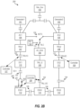
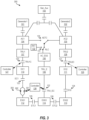
- FIGS. 2A and 2B depict circuit diagrams of another electric power distribution system 200 according to one or more embodiments described herein.
- the electric power distribution system 200 is modified relative to the electric power distribution system 100 of FIG. 1 to accommodate the scenario where the TRU1 107 fails or is otherwise unavailable, but the primary system controller does not automatically open EC1 123.
- partial control of the primary power feed to ESS1 112 is given to an alterative system controller (e.g., the controller 127).
- the EC1 123 is placed in series with a diode-diode bypass arrangement 240 that includes a diode 242 in parallel with a diode bypass 241.
- Electric power selectively flows through one of the diode 242 or the diode bypass 241, as determined by the contactor 243 (also referred to as a "diode bypass contactor") controlled by the controller 128, based on whether the TRU1 107 is providing power to DC1 110.
- the contactor 243 also referred to as a "diode bypass contactor”
- the alternate system controller In normal operation, where TRU1 is available, the alternate system controller would set the contactor to the no-diode position. If the alternate system controller determines that TRU1 is not available (due to battery discharging indication, low bus voltage, emergency condition indication, etc.), it would switch the contactor to the diode position. The diode would prevent the DC essential bus alternate power source from back-feeding onto DC ESS1 123 if EC1 123 were to fail to open due to the primary system failure. Since this diode path would not be used except in conditions where normal power is not available, this would allow for float charging of the batteries.
- FIG. 2A shows the arrangement of electric power flowing from TRU1 107 through TRU1C 120 to DC1 110.
- the electric power (DC) then passes from DC1 110 to the ESS1 112 via the diode bypass 241 as shown.
- FIG. 2B shows the arrangement of electric power stopping flowing from TRU1 107.
- electric power passes to ESS1 112 from another source (e.g., the TRU2 108 via ESS3 114, the TRU_E 109 via ESS 114, etc.).
- the controller 128 selectively controls the contactor 243 to activate the diode 242 branch of the diode-diode bypass arrangement 240. This presents power to feed back into the DC1 110 (and further, such as to the TRU1 107) from the ESS1 112.
- FIG. 3 depicts a circuit diagram of yet another electric power distribution system 300 according to one or more embodiments described herein.
- the diode 242 is shown in parallel with a contactor 351 instead of in one of the pole positions.
- the contactor 351 is opened, and the diode 242 prevents power back flowing through ESS1 112 to DC1 110.
- Another potential configuration replaces EC1 123 with the arrangement 240 or 350 and a fuse (not shown) in series with the arrangement 240 or 350. This removes ability of the controller 127 to remove power from only ESS1 112 without impacting ability to power DC1 110, but the fuse would provide protection for TRU1 107 and DC1 110 against ESS1 112 faults.
Landscapes
- Engineering & Computer Science (AREA)
- Power Engineering (AREA)
- Aviation & Aerospace Engineering (AREA)
- Business, Economics & Management (AREA)
- Emergency Management (AREA)
- Direct Current Feeding And Distribution (AREA)
Abstract
Description
- One or more embodiments described herein relate to a scheme for controlling a direct current (DC) bus.
- Aircraft use electric power distribution systems (EPDSs) to distribute electric power that is used to operate aircraft systems and/or components. For example, a generator generates electric power, which is distributed to aircraft systems and/or components, such as control systems, actuators, motors, electronics, and/or the like, including combinations and/or multiples thereof throughout the aircraft. The generator may be associated with a main engine of the aircraft, auxiliary systems (e.g., an auxiliary generator), and/or backup systems (e.g., a ram air turbine (RAT)). In some cases, the generator generates alternating current (AC) electric power, which is used by some aircraft systems and/or components. In some cases, the AC electric power can be converted to DC electric power, which is use by some other aircraft systems and/or components.
- In one aspect, an electric power distribution system is provided. The electric power distribution system (EPDS) includes a transformer rectifier unit (TRU) that receives alternating current (AC) electric power from an AC electric power source during a first state of operation. The EPDS further includes a direct current (DC) electric power source that receives the DC electric power from the TRU which is converted from the AC electric power during the first state of operation. The EPDS further includes a DC essential bus that receives the DC electric power from the DC electric power source during the first state of operation and that receives the DC electric power from another source during a second state of operation. The EPDS further includes a controller to selectively engage a diode bypass contactor to enable a diode disposed between the DC essential bus and the DC electric power source during the second state of operation, and selectively engage the diode bypass contactor to enable a diode bypass disposed between the DC essential bus and the DC electric power source during the first state of operation.
- In embodiments of the electric power distribution system may include the AC electric power source that generates the AC electric power.
- In embodiments of the electric power distribution system may include a TRU contactor disposed between the TRU and the DC electric power source.
- In embodiments of the electric power distribution system may include that the another source is a ram air turbine.
- In embodiments of the electric power distribution system may include that the AC electric power source is a first generator associated with a first gas turbine engine of an aircraft.
- In embodiments of the electric power distribution system may include that the another source is a second generator associated with a second gas turbine engine of the aircraft.
- In embodiments of the electric power distribution system may include that the diode is arranged in parallel to the diode bypass contactor.
- In embodiments of the electric power distribution system may include that the DC essential bus receives the DC electric power from the DC electric power source via an electrical contactor.
- In embodiments of the electric power distribution system may include that the DC essential bus receives the DC electric power from the DC electric power source via a fuse.
- In another aspect, a controller stores instructions to cause the controller to selectively engage a contactor of an electric power distribution system to enable a diode bypass disposed between a direct current (DC) essential bus and a DC electric power source during a first state of operation and to selectively engage the contactor to enable a diode disposed between the DC essential bus and the DC electric power source during a second state of operation. The DC essential bus receives DC electric power from the DC electric power source during the first state of operation and receives the DC electric power from another source during the second state of operation.
- In embodiments of the controller may include that the electric power distribution system includes a transformer rectifier unit (TRU) that receives alternating current (AC) electric power from the AC electric power source during the first state of operation.
- In embodiments of the controller may include that the electric power distribution system includes the DC electric power source that receives the DC electric power from the TRU which is converted from the AC electric power during the first state of operation.
- In embodiments of the controller may include that the electric power distribution system includes the DC essential bus that receives the DC electric power from the DC electric power source during the first state of operation and that receives the DC electric power from the another source during the second state of operation.
- In embodiments of the controller may include that the electric power distribution system further includes the alternating current (AC) electric power source that generates the AC electric power.
- In embodiments of the controller may include that the electric power distribution system further includes a TRU contactor disposed between the TRU and the DC electric power source.
- In embodiments of the controller may include that the another source is a ram air turbine.
- In embodiments of the controller may include that the AC electric power source is a first generator associated with a first gas turbine engine of an aircraft.
- In embodiments of the controller may include that the another source is a second generator associated with a second gas turbine engine of the aircraft.
- In embodiments of the controller may include that the diode is arranged in parallel to the diode bypass contactor.
- The above features and advantages, and other features and advantages, of the disclosure are readily apparent from the following detailed description when taken in connection with the accompanying drawings.
- The following descriptions should not be considered limiting in any way. With reference to the accompanying drawings, like elements are numbered alike:
-
FIG. 1 depicts a circuit diagram of an electric power distribution system according to one or more embodiments described herein; -
FIGS. 2A and2B depict circuit diagrams of another electric power distribution system according to one or more embodiments described herein; and -
FIG. 3 depicts a circuit diagram of yet another electric power distribution system according to one or more embodiments described herein. - A detailed description of one or more embodiments of the disclosed apparatus and method are presented herein by way of exemplification and not limitation with reference to the Figures.
- Embodiments described herein provide for a scheme for controlling a DC essential bus. A DC essential bus is a power bus that provides direct current electric power to systems and/or components considered "critical" to the aircraft, such as flight controls, navigation, radio/communications, and/or the like, including combinations and/or multiples thereof. It is desirable to provide electrical power to such "critical" systems and/or components even in the event of power failure, emergency events, and/or the like. For example, if the generators associated with the aircraft's engines become inoperable, a ram air turbine (RAT) can be used to generate limited power, which can be used to power "critical" systems and/or components. Other systems and/or components not considered to be "critical" (such as passenger entertainment systems and/or the like) may not receive electric power in such cases.
- Conventionally, a DC essential bus is able to be fed from a primary or normal power source such as a transformer rectifier unit (TRU), such as via a DC bus, and also fed from an alternate or emergency power source such as an essential TRU, which receives electric power from a primary system generator and/or a RAT.
-
FIG. 1 depicts a circuit diagram of an electric power distribution system (EPDS) 100 according to one or more embodiments described herein. In this example,generator1 101,generator2 102, and/orgen_aux 103 generate electric power through the electricpower distribution system 100. Particularly, AC electric power flows fromgenerator1 101,generator2 102, and/orgen_aux 103 as shown to one or more AC units AC1 104, AC2 105, and AC_ESS 106. AC electric power can also be generated, in an electrical emergency for example, by RAT 132. AC electric power through portions of the electricpower distribution system 100 to/from AC1 104, AC2 105, and AC_ESS 106 can be selectively controlled, via one or more ofcontrollers - When TRU1 is powered, primary system contactors TRU1C 120 and EC1 123 are closed to power DC ESS 1 112. When TRU1 is not powered, TRU1C 120 and EC1 123 are opened, and alternate system contactor ETC1 125 is closed to
power ESS1 112 from an alternate source (e.g., TRU_E 109 which may be powered by RAT 132 or TRU2 108 if TRU_E 109 is not available). EC1 123 is opened to prevent overloading the alternate power source. To prevent a single controller (e.g., the controller 127) from being able to isolateESS1 112, control of EC1 123 and ETC1 125 may be distributed to multiple controllers (e.g., multiple of thecontroller 127 or a dissimilar controller), where a first system controller (e.g., the controller 127) controlsEC1 123 and a second system controller (e.g., the controller 128) controlsETC1 125. In another example, ETC1 125 is closed via interlock if EC1 123 opens. A similar arrangement is also possible for thecomponents TRU2 108,DC2 111, andESS2 113 using TRU2C 121, EC2 124, andETC2 126. Another similar arrangement is also possible for the components TRU_E109 andESS3 114 via TRU_EC 122. - According to one or more embodiments described herein, the
controller 127, thecontroller 128, and/or thecontroller 129 can be implemented as instructions stored on a computer-readable storage medium, as hardware modules, as special-purpose hardware (e.g., application specific hardware, application specific integrated circuits (ASICs), application specific special processors (ASSPs), field programmable gate arrays (FPGAs), as embedded controllers, hardwired circuitry, etc.), or as some combination or combinations of these. According to aspects of the present disclosure, one or more of thecontrollers controllers - To account for the case where a primary system failure could result in loss of
TRU1 107 butEC1 123 is not automatically opened, some conventional approaches use an AC relay and interlock to openTRU1C 120 andEC1 123 ifTRU1 107 input power is lost. However, there may not be sufficient room in the AC system for an AC relay. Another alternative approach is to place a diode betweenDC1 110 andESS1 112 that would prevent back feeding fromESS1 112 to DC1 110 ifTRU1 107 is lost. However, the use of a diode by itself may preclude float charging of one or more batteries on the ESS DC busses due to voltage drop associated with the diodes. In such arrangements, a separate battery charger may be required. Another alternative approach uses a crew alert system, which provides messages to flight crew, which requires flight crew action to reconfigure the system manually in such an event. However, approaches that rely on flight crew action may be undesirable due to increased workload and may not be sufficient for compliance with certain safety requirements depending on the criticality of the crew alert system message available and loads associated with the essential bus. -
FIGS. 2A and2B depict circuit diagrams of another electricpower distribution system 200 according to one or more embodiments described herein. It this example, the electricpower distribution system 200 is modified relative to the electricpower distribution system 100 ofFIG. 1 to accommodate the scenario where theTRU1 107 fails or is otherwise unavailable, but the primary system controller does not automaticallyopen EC1 123. In the example ofFIGS. 2A and2B , partial control of the primary power feed toESS1 112 is given to an alterative system controller (e.g., the controller 127). Further, in this example, theEC1 123 is placed in series with a diode-diode bypass arrangement 240 that includes adiode 242 in parallel with adiode bypass 241. Electric power selectively flows through one of thediode 242 or thediode bypass 241, as determined by the contactor 243 (also referred to as a "diode bypass contactor") controlled by thecontroller 128, based on whether theTRU1 107 is providing power toDC1 110. - In normal operation, where TRU1 is available, the alternate system controller would set the contactor to the no-diode position. If the alternate system controller determines that TRU1 is not available (due to battery discharging indication, low bus voltage, emergency condition indication, etc.), it would switch the contactor to the diode position. The diode would prevent the DC essential bus alternate power source from back-feeding onto
DC ESS1 123 ifEC1 123 were to fail to open due to the primary system failure. Since this diode path would not be used except in conditions where normal power is not available, this would allow for float charging of the batteries. - Additionally, if the alternate system controller were to fail and erroneously control this new contactor to the diode position, this would still allow the primary system to power the DC ESS bus, preventing the possibility of an alternate system controller failure from resulting in isolation of the DC ESS bus.
-
FIG. 2A shows the arrangement of electric power flowing fromTRU1 107 throughTRU1C 120 toDC1 110. The electric power (DC) then passes fromDC1 110 to theESS1 112 via thediode bypass 241 as shown. -
FIG. 2B shows the arrangement of electric power stopping flowing fromTRU1 107. In such cases, electric power passes to ESS1 112 from another source (e.g., theTRU2 108 viaESS3 114, theTRU_E 109 viaESS 114, etc.). Thecontroller 128 selectively controls thecontactor 243 to activate thediode 242 branch of the diode-diode bypass arrangement 240. This presents power to feed back into the DC1 110 (and further, such as to the TRU1 107) from theESS1 112. - Another potential contactor-diode configuration is shown in
FIG. 3 . Particularly,FIG. 3 depicts a circuit diagram of yet another electricpower distribution system 300 according to one or more embodiments described herein. In thisarrangement 350, thediode 242 is shown in parallel with acontactor 351 instead of in one of the pole positions. WhenTRU1 107 is providing power toDC1 110, the electric power flows through thecontactor 351 toESS1 112. However, whenTRU1 107 is not providing power, thecontactor 351 is opened, and thediode 242 prevents power back flowing throughESS1 112 toDC1 110. - Another potential configuration replaces
EC1 123 with thearrangement arrangement controller 127 to remove power from only ESS1 112 without impacting ability to powerDC1 110, but the fuse would provide protection forTRU1 107 andDC1 110 againstESS1 112 faults. - The term "about" is intended to include the degree of error associated with measurement of the particular quantity based upon the equipment available at the time of filing the application.
- The terminology used herein is for the purpose of describing particular embodiments only and is not intended to be limiting of the present disclosure. As used herein, the singular forms "a", "an" and "the" are intended to include the plural forms as well, unless the context clearly indicates otherwise. It will be further understood that the terms "comprises" and/or "comprising," when used in this specification, specify the presence of stated features, integers, steps, operations, elements, and/or components, but do not preclude the presence or addition of one or more other features, integers, steps, operations, element components, and/or groups thereof.
- While the present disclosure has been described with reference to an exemplary embodiment or embodiments, it will be understood by those skilled in the art that various changes may be made without departing from the scope of the invention as defined by the claims. In addition, many modifications may be made to adapt a particular situation or material to the teachings of the present disclosure without departing from the scope of the claims. Therefore, it is intended that the present disclosure not be limited to the particular embodiment disclosed as the best mode contemplated for carrying out this present disclosure, but that the present disclosure will include all embodiments falling within the scope of the claims.
Claims (15)
- An electric power distribution system comprising:a transformer rectifier unit, TRU, (107, 108, 109) that receives alternating current, AC, electric power from an AC electric power source (104, 105, 106) during a first state of operation;a direct current, DC, electric power source (110) that receives the DC electric power from the TRU which is converted from the AC electric power during the first state of operation;a DC essential bus (112) that receives the DC electric power from the DC electric power source during the first state of operation and that receives the DC electric power from another source during a second state of operation; anda controller (127, 128, 129) to:selectively engage a diode bypass contactor (243) to enable a diode (242) disposed between the DC essential bus and the DC electric power source during the second state of operation, andselectively engage the diode bypass contactor to enable a diode bypass (241) disposed between the DC essential bus and the DC electric power source during the first state of operation.
- The electric power distribution system of claim 1, further comprising:
the AC electric power source that generates the AC electric power. - The electric power distribution system of claim 1 or 2, further comprising:
a TRU contactor disposed between the TRU and the DC electric power source. - The electric power distribution system of any preceding claim, wherein the another source is a ram air turbine.
- The electric power distribution system of any preceding claim, wherein the AC electric power source is a first generator associated with a first gas turbine engine of an aircraft, and optionally wherein the another source is a second generator associated with a second gas turbine engine of the aircraft.
- The electric power distribution system of any preceding claim, wherein the diode (242) is arranged in parallel to the diode bypass contactor (243).
- The electric power distribution system of any preceding claim, wherein the DC essential bus receives the DC electric power from the DC electric power source via an electrical contactor, or wherein the DC essential bus receives the DC electric power from the DC electric power source via a fuse.
- A controller storing instructions to cause the controller to:selectively engage a contactor of an electric power distribution system to enable a diode bypass (241) disposed between a direct current, DC, essential bus (112) and a DC electric power source (110) during a first state of operation; andselectively engage the contactor to enable a diode (242) disposed between the DC essential bus and the DC electric power source during a second state of operation,wherein the DC essential bus receives DC electric power from the DC electric power source during the first state of operation and receives the DC electric power from another source during the second state of operation.
- The controller of claim 8, wherein the electric power distribution system comprises:
a transformer rectifier unit, TRU, (107, 108, 109) that receives alternating current, AC, electric power from the AC electric power source during the first state of operation. - The controller of claim 9, wherein the electric power distribution system comprises:
the DC electric power source that receives the DC electric power from the TRU which is converted from the AC electric power during the first state of operation. - The controller of claim 10, wherein the electric power distribution system comprises:
the DC essential bus that receives the DC electric power from the DC electric power source during the first state of operation and that receives the DC electric power from the another source during the second state of operation. - The controller of claim 11, wherein the electric power distribution system further comprises:
the alternating current, AC, electric power source (104, 105, 106) that generates the AC electric power. - The controller of claim 12, wherein the electric power distribution system further comprises:
a TRU contactor disposed between the TRU and the DC electric power source. - The controller of claim 12 or 13, wherein the AC electric power source is a first generator associated with a first gas turbine engine of an aircraft, and optionally wherein the another source is a second generator associated with a second gas turbine engine of the aircraft.
- The controller of any of claims 8 to 14, wherein the diode is arranged in parallel to the diode bypass contactor.
Applications Claiming Priority (1)
| Application Number | Priority Date | Filing Date | Title |
|---|---|---|---|
| US17/749,319 US12107409B2 (en) | 2022-05-20 | 2022-05-20 | Direct current bus control scheme |
Publications (1)
| Publication Number | Publication Date |
|---|---|
| EP4280407A1 true EP4280407A1 (en) | 2023-11-22 |
Family
ID=86469307
Family Applications (1)
| Application Number | Title | Priority Date | Filing Date |
|---|---|---|---|
| EP23174373.3A Pending EP4280407A1 (en) | 2022-05-20 | 2023-05-19 | Direct current bus control scheme |
Country Status (2)
| Country | Link |
|---|---|
| US (1) | US12107409B2 (en) |
| EP (1) | EP4280407A1 (en) |
Citations (4)
| Publication number | Priority date | Publication date | Assignee | Title |
|---|---|---|---|---|
| EP2648322A1 (en) * | 2012-04-05 | 2013-10-09 | Hamilton Sundstrand Corporation | Power interruption bridge circuit |
| US20160280394A1 (en) * | 2013-10-04 | 2016-09-29 | Ge Aviation Systems Llc | Power distribution system for an aircraft |
| EP3883081A1 (en) * | 2020-03-18 | 2021-09-22 | Hamilton Sundstrand Corporation | Dc bus voltage input into rat auto-deploy |
| CN113765211A (en) * | 2021-10-09 | 2021-12-07 | 陕西航空电气有限责任公司 | Method for uninterrupted power supply of direct-current emergency bus bar in aviation power distribution system |
Family Cites Families (7)
| Publication number | Priority date | Publication date | Assignee | Title |
|---|---|---|---|---|
| US8587146B2 (en) | 2011-06-07 | 2013-11-19 | Hamilton Sundstrand Corporation | Solid state contactor assembly |
| US9114888B2 (en) | 2012-02-22 | 2015-08-25 | Hamilton Sundstrand Corporation | RAM air turbine smoke isolation |
| US11011908B2 (en) * | 2019-08-06 | 2021-05-18 | Hamilton Sunstrand Corporation | System and method for adding a high voltage DC source to a power bus |
| CN115693743A (en) * | 2020-02-27 | 2023-02-03 | 华为数字能源技术有限公司 | Power supply device, power supply system and data center |
| US11133672B1 (en) | 2020-03-06 | 2021-09-28 | Hamilton Sundstrand Corporation | System and method for adding a high voltage DC source to a power bus |
| US11702222B2 (en) * | 2020-03-18 | 2023-07-18 | Hamilton Sundstrand Corporation | DC contactor input into RAT auto-deploy |
| US11996690B2 (en) * | 2021-11-05 | 2024-05-28 | Hamilton Sundstrand Corporation | Transformer rectifier unit (TRU) backfeed interlock |
-
2022
- 2022-05-20 US US17/749,319 patent/US12107409B2/en active Active
-
2023
- 2023-05-19 EP EP23174373.3A patent/EP4280407A1/en active Pending
Patent Citations (4)
| Publication number | Priority date | Publication date | Assignee | Title |
|---|---|---|---|---|
| EP2648322A1 (en) * | 2012-04-05 | 2013-10-09 | Hamilton Sundstrand Corporation | Power interruption bridge circuit |
| US20160280394A1 (en) * | 2013-10-04 | 2016-09-29 | Ge Aviation Systems Llc | Power distribution system for an aircraft |
| EP3883081A1 (en) * | 2020-03-18 | 2021-09-22 | Hamilton Sundstrand Corporation | Dc bus voltage input into rat auto-deploy |
| CN113765211A (en) * | 2021-10-09 | 2021-12-07 | 陕西航空电气有限责任公司 | Method for uninterrupted power supply of direct-current emergency bus bar in aviation power distribution system |
Also Published As
| Publication number | Publication date |
|---|---|
| US20230378743A1 (en) | 2023-11-23 |
| US12107409B2 (en) | 2024-10-01 |
Similar Documents
| Publication | Publication Date | Title |
|---|---|---|
| EP2408085B1 (en) | Methods for aircraft emergency power management | |
| US7759821B2 (en) | System and process for direct current power supply of an electrical network on board an aircraft | |
| EP2648322B1 (en) | Power interruption bridge circuit | |
| US9815541B2 (en) | Boat with electric drive | |
| US9964044B2 (en) | Auxiliary power unit starting system for an aircraft | |
| US9935494B2 (en) | Elevator power supply for inverter controller | |
| JP2001502518A (en) | System and method for continuously supplying power to a mounted electric device | |
| WO2024023305A1 (en) | An energy distribution system | |
| US10087902B2 (en) | Power limiting generator control unit (GCU) | |
| US9114888B2 (en) | RAM air turbine smoke isolation | |
| EP4280407A1 (en) | Direct current bus control scheme | |
| EP3883081A1 (en) | Dc bus voltage input into rat auto-deploy | |
| EP3883085A1 (en) | Dc contactor input into rat auto-deploy | |
| CN113745058B (en) | Control method of direct-current emergency bus bar contactor in aviation power distribution system | |
| US11527976B2 (en) | AC bus tie contactor input into rat auto-deploy | |
| RU2232109C1 (en) | Method of electric power supply for on-board systems of flying vehicle | |
| US20040125518A1 (en) | Reverse current protection device | |
| US20130307337A1 (en) | Power distribution system | |
| Bayles | 2 Aircraft Electric Power System Design, Control, and Protection | |
| HK1217933B (en) | Boat with electric drive |
Legal Events
| Date | Code | Title | Description |
|---|---|---|---|
| PUAI | Public reference made under article 153(3) epc to a published international application that has entered the european phase |
Free format text: ORIGINAL CODE: 0009012 |
|
| STAA | Information on the status of an ep patent application or granted ep patent |
Free format text: STATUS: THE APPLICATION HAS BEEN PUBLISHED |
|
| AK | Designated contracting states |
Kind code of ref document: A1 Designated state(s): AL AT BE BG CH CY CZ DE DK EE ES FI FR GB GR HR HU IE IS IT LI LT LU LV MC ME MK MT NL NO PL PT RO RS SE SI SK SM TR |
|
| STAA | Information on the status of an ep patent application or granted ep patent |
Free format text: STATUS: REQUEST FOR EXAMINATION WAS MADE |
|
| 17P | Request for examination filed |
Effective date: 20240515 |
|
| RBV | Designated contracting states (corrected) |
Designated state(s): AL AT BE BG CH CY CZ DE DK EE ES FI FR GB GR HR HU IE IS IT LI LT LU LV MC ME MK MT NL NO PL PT RO RS SE SI SK SM TR |