EP4280311A1 - Positive-electrode active material composition, positive electrode plate, secondary battery, battery module, battery pack and electric apparatus - Google Patents
Positive-electrode active material composition, positive electrode plate, secondary battery, battery module, battery pack and electric apparatus Download PDFInfo
- Publication number
- EP4280311A1 EP4280311A1 EP22925227.5A EP22925227A EP4280311A1 EP 4280311 A1 EP4280311 A1 EP 4280311A1 EP 22925227 A EP22925227 A EP 22925227A EP 4280311 A1 EP4280311 A1 EP 4280311A1
- Authority
- EP
- European Patent Office
- Prior art keywords
- positive electrode
- active material
- optionally
- electrode active
- material composition
- Prior art date
- Legal status (The legal status is an assumption and is not a legal conclusion. Google has not performed a legal analysis and makes no representation as to the accuracy of the status listed.)
- Pending
Links
Images


Classifications
-
- H—ELECTRICITY
- H01—ELECTRIC ELEMENTS
- H01M—PROCESSES OR MEANS, e.g. BATTERIES, FOR THE DIRECT CONVERSION OF CHEMICAL ENERGY INTO ELECTRICAL ENERGY
- H01M4/00—Electrodes
- H01M4/02—Electrodes composed of, or comprising, active material
- H01M4/62—Selection of inactive substances as ingredients for active masses, e.g. binders, fillers
-
- H—ELECTRICITY
- H01—ELECTRIC ELEMENTS
- H01M—PROCESSES OR MEANS, e.g. BATTERIES, FOR THE DIRECT CONVERSION OF CHEMICAL ENERGY INTO ELECTRICAL ENERGY
- H01M4/00—Electrodes
- H01M4/02—Electrodes composed of, or comprising, active material
- H01M4/13—Electrodes for accumulators with non-aqueous electrolyte, e.g. for lithium-accumulators; Processes of manufacture thereof
- H01M4/136—Electrodes based on inorganic compounds other than oxides or hydroxides, e.g. sulfides, selenides, tellurides, halogenides or LiCoFy
-
- C—CHEMISTRY; METALLURGY
- C01—INORGANIC CHEMISTRY
- C01B—NON-METALLIC ELEMENTS; COMPOUNDS THEREOF; METALLOIDS OR COMPOUNDS THEREOF NOT COVERED BY SUBCLASS C01C
- C01B25/00—Phosphorus; Compounds thereof
- C01B25/16—Oxyacids of phosphorus; Salts thereof
- C01B25/26—Phosphates
- C01B25/38—Condensed phosphates
- C01B25/42—Pyrophosphates
- C01B25/425—Pyrophosphates of alkali metals
-
- C—CHEMISTRY; METALLURGY
- C01—INORGANIC CHEMISTRY
- C01B—NON-METALLIC ELEMENTS; COMPOUNDS THEREOF; METALLOIDS OR COMPOUNDS THEREOF NOT COVERED BY SUBCLASS C01C
- C01B25/00—Phosphorus; Compounds thereof
- C01B25/16—Oxyacids of phosphorus; Salts thereof
- C01B25/26—Phosphates
- C01B25/45—Phosphates containing plural metal, or metal and ammonium
-
- H—ELECTRICITY
- H01—ELECTRIC ELEMENTS
- H01M—PROCESSES OR MEANS, e.g. BATTERIES, FOR THE DIRECT CONVERSION OF CHEMICAL ENERGY INTO ELECTRICAL ENERGY
- H01M4/00—Electrodes
- H01M4/02—Electrodes composed of, or comprising, active material
- H01M4/13—Electrodes for accumulators with non-aqueous electrolyte, e.g. for lithium-accumulators; Processes of manufacture thereof
- H01M4/131—Electrodes based on mixed oxides or hydroxides, or on mixtures of oxides or hydroxides, e.g. LiCoOx
-
- H—ELECTRICITY
- H01—ELECTRIC ELEMENTS
- H01M—PROCESSES OR MEANS, e.g. BATTERIES, FOR THE DIRECT CONVERSION OF CHEMICAL ENERGY INTO ELECTRICAL ENERGY
- H01M4/00—Electrodes
- H01M4/02—Electrodes composed of, or comprising, active material
- H01M4/36—Selection of substances as active materials, active masses, active liquids
- H01M4/362—Composites
- H01M4/366—Composites as layered products
-
- H—ELECTRICITY
- H01—ELECTRIC ELEMENTS
- H01M—PROCESSES OR MEANS, e.g. BATTERIES, FOR THE DIRECT CONVERSION OF CHEMICAL ENERGY INTO ELECTRICAL ENERGY
- H01M4/00—Electrodes
- H01M4/02—Electrodes composed of, or comprising, active material
- H01M4/36—Selection of substances as active materials, active masses, active liquids
- H01M4/58—Selection of substances as active materials, active masses, active liquids of inorganic compounds other than oxides or hydroxides, e.g. sulfides, selenides, tellurides, halogenides or LiCoFy; of polyanionic structures, e.g. phosphates, silicates or borates
- H01M4/5825—Oxygenated metallic salts or polyanionic structures, e.g. borates, phosphates, silicates, olivines
-
- H—ELECTRICITY
- H01—ELECTRIC ELEMENTS
- H01M—PROCESSES OR MEANS, e.g. BATTERIES, FOR THE DIRECT CONVERSION OF CHEMICAL ENERGY INTO ELECTRICAL ENERGY
- H01M4/00—Electrodes
- H01M4/02—Electrodes composed of, or comprising, active material
- H01M4/62—Selection of inactive substances as ingredients for active masses, e.g. binders, fillers
- H01M4/624—Electric conductive fillers
- H01M4/625—Carbon or graphite
-
- C—CHEMISTRY; METALLURGY
- C01—INORGANIC CHEMISTRY
- C01P—INDEXING SCHEME RELATING TO STRUCTURAL AND PHYSICAL ASPECTS OF SOLID INORGANIC COMPOUNDS
- C01P2004/00—Particle morphology
- C01P2004/80—Particles consisting of a mixture of two or more inorganic phases
- C01P2004/82—Particles consisting of a mixture of two or more inorganic phases two phases having the same anion, e.g. both oxidic phases
- C01P2004/84—Particles consisting of a mixture of two or more inorganic phases two phases having the same anion, e.g. both oxidic phases one phase coated with the other
-
- C—CHEMISTRY; METALLURGY
- C01—INORGANIC CHEMISTRY
- C01P—INDEXING SCHEME RELATING TO STRUCTURAL AND PHYSICAL ASPECTS OF SOLID INORGANIC COMPOUNDS
- C01P2006/00—Physical properties of inorganic compounds
- C01P2006/40—Electric properties
-
- H—ELECTRICITY
- H01—ELECTRIC ELEMENTS
- H01M—PROCESSES OR MEANS, e.g. BATTERIES, FOR THE DIRECT CONVERSION OF CHEMICAL ENERGY INTO ELECTRICAL ENERGY
- H01M4/00—Electrodes
- H01M4/02—Electrodes composed of, or comprising, active material
- H01M2004/026—Electrodes composed of, or comprising, active material characterised by the polarity
- H01M2004/028—Positive electrodes
-
- Y—GENERAL TAGGING OF NEW TECHNOLOGICAL DEVELOPMENTS; GENERAL TAGGING OF CROSS-SECTIONAL TECHNOLOGIES SPANNING OVER SEVERAL SECTIONS OF THE IPC; TECHNICAL SUBJECTS COVERED BY FORMER USPC CROSS-REFERENCE ART COLLECTIONS [XRACs] AND DIGESTS
- Y02—TECHNOLOGIES OR APPLICATIONS FOR MITIGATION OR ADAPTATION AGAINST CLIMATE CHANGE
- Y02E—REDUCTION OF GREENHOUSE GAS [GHG] EMISSIONS, RELATED TO ENERGY GENERATION, TRANSMISSION OR DISTRIBUTION
- Y02E60/00—Enabling technologies; Technologies with a potential or indirect contribution to GHG emissions mitigation
- Y02E60/10—Energy storage using batteries
Definitions
- the present application relates to the field of battery technology, and in particular to a positive electrode active material composition, a positive electrode plate, a secondary battery, a battery module, a battery pack and an electric device.
- the positive electrode plate of a secondary battery mainly includes a current collector and an electrode film layer containing a positive electrode active material.
- the positive electrode active material can be formed into a positive electrode slurry together with a dispersion medium and coated on the current collector of the electrode to form the positive electrode plate.
- the positive electrode active material is usually used in the form of powder. Due to the large specific surface area and small particles of the positive electrode material powder, it is difficult to disperse the powder during the preparation of positive electrode slurry, the slurry viscosity is high and the solid content is difficult to increase, which in turn leads to defects such as cracks, stripes, uneven weight, particle scratches or pinholes easily during the coating of the electrode plate.
- the present application is carried out in view of the above subject matter, and one of the objectives is to provide a composition including a positive electrode active material and a flexible dispersant to improve the poor dispersion of the positive electrode active material powder and the high viscosity of the slurry during the preparation of the positive electrode slurry.
- the present application provides a positive electrode active material composition, a positive electrode plate, a secondary battery, a battery module including the secondary battery, a battery pack including the battery module, and an electric device including the secondary battery, the battery module or the battery pack.
- a first aspect of the present application provides a positive electrode active material composition including a positive electrode active material and a dispersant, where the positive electrode active material includes a core and a shell coating the core,
- a mass percentage content of the first monomeric unit is M1, M1 is 10%-55%, optionally 25%-55%.
- a mass percentage content of the second monomeric unit is M2, M2 is 40%-80%, optionally 50%-70%.
- a mass percentage content of the third monomeric unit is M3, M3 is 0%-10% and optionally 0.001%-2%.
- M3/(M2+M3) is 0%-5%, optionally 0.001%-1%.
- the polymer is hydrogenated nitrile butadiene rubber.
- the polymer has a weight average molar mass of 50,000-500,000, optionally 150,000-350,000.
- the dispersant has a mass percentage content of X1, X1 is 0.05%-1%, optionally 0.1%-0.5%.
- the infiltrant includes one or more selected from a small-molecule organic solvent and a low-molecular-weight polymer;
- a mass percentage content of the infiltrant is X2, X2 is 0.05%-2%, optionally 0.2%-0.8%.
- X1/X2 is 0.05-20, optionally 0.1-1, and further 0.3-0.8.
- phosphate in the first coating layer has a crystal plane spacing of 0.345-0.358 nm and an angle of 24.25°-26.45° in the crystal direction (111); the pyrophosphate of the first coating layer has a crystal plane spacing of 0.293-0.326 nm and an angle of 26.41°-32.57° in the crystal direction (111).
- the ratio of y to 1-y in the core is 1:10 to 10:1, optionally 1:4 to 1:1.
- the ratio of z to 1-z in the core is 1:9 to 1:999, optionally 1:499 to 1:249.
- the first coating layer has a coating amount greater than 0wt% and less than or equal to 7wt%, optionally 4-5.6wt%, with respect to a weight of the core.
- a weight ratio of pyrophosphate to phosphate in the first coating layer is 1:3 to 3:1, optionally 1:3 to 1:1.
- the pyrophosphate and phosphate each independently has a crystallinity of 10% to 100%, optionally 50% to 100%.
- the second coating layer has a coating amount of greater than 0wt% and less than or equal to 6wt%, optionally 3-5wt%, with respect to a weight of the core.
- the A is at least two selected from Fe, Ti, V, Ni, Co, and Mg.
- the positive electrode active material has a Li/Mn antisite defect concentration of 4% or less, optionally 2% or less.
- the positive electrode active material has a lattice change rate of 6% or less, optionally 4% or less.
- the positive electrode active material has a surface oxygen valence state of -1.88 or less, optionally -1.98 to -1.88.
- the positive electrode active material has a compaction density of 2.0 g/cm 3 or higher, optionally 2.2 g/cm 3 or higher.
- a second aspect of the present application provides a positive electrode slurry including the positive electrode active material composition of the first aspect of the present application; optionally also including one or more of a solvent, a positive electrode conductive agent, and a positive electrode binder.
- the solvent includes N-methylpyrrolidone (NMP).
- the positive electrode binder includes one or more selected from polyvinylidene fluoride (PVDF), polytetrafluoroethylene (PTFE), vinylidene fluoride-tetrafluoroethylene-propylene terpolymers, vinylidene fluoride-hexafluoropropylene-tetrafluoroethylene terpolymers, vinylidene fluoride-hexafluoropropylene copolymers, and fluorinated acrylate resin.
- PVDF polyvinylidene fluoride
- PTFE polytetrafluoroethylene
- PTFE polytetrafluoroethylene
- vinylidene fluoride-tetrafluoroethylene-propylene terpolymers vinylidene fluoride-hexafluoropropylene-tetrafluoroethylene terpolymers
- vinylidene fluoride-hexafluoropropylene copolymers vinylidene fluoride-hexa
- the positive electrode conductive agent includes one or more selected from superconducting carbon, acetylene black, carbon black, Ketjen black, carbon dots, carbon nanotubes, graphene, and carbon nanofibers.
- the positive electrode slurry has a solid content of 40%-70%, optionally 55%-65%.
- the positive electrode slurry has a viscosity of 3000 mpa.s-50,000 mpa.s at 20°C, optionally 10,000 mpa.s-20,000 mpa.s.
- a third aspect of the present application provides a positive electrode plate including a positive electrode current collector and a positive electrode film layer disposed on at least one surface of the positive electrode current collector, the positive electrode film layer includes the positive electrode active material composition of the first aspect of the present application or is made by coating the positive electrode slurry of the second aspect of the present application.
- a coating method is selected from lifting method, film- pulling method, electrostatic spraying method and spin coating method.
- the positive electrode conductive agent has a mass percentage content of W5, W5 is 2.5% or less, optionally 0.1%-1%.
- a fourth aspect of the present application provides a secondary battery, which includes the positive electrode plate of the third aspect of the present application.
- a fifth aspect of the present application provides a battery module including the positive electrode plate of the third aspect of the present application, or the secondary battery of the fourth aspect of the present application.
- a sixth aspect of the present application provides a battery pack including the positive electrode plate of the third aspect of the present application, the secondary battery of the fourth aspect of the present application, or the battery module of the fifth aspect of the present application.
- a seventh aspect of the present application provides an electric device including the positive electrode plate of the third aspect of the present application, or the secondary battery of the fourth aspect of the present application, or the battery module of the fifth aspect of the present application, or the battery pack of the sixth aspect of the present application.
- the positive electrode active material composition provided in the present application can solve the problems of poor dispersion of positive electrode active material powder and high viscosity of slurry in the preparation of positive electrode slurry, and improve the processing performance of positive electrode slurry as well as the performance of secondary battery.
- ranges disclosed in the application is defined in the form of lower limit and upper limit, and the given range is limited by selecting a lower limit and an upper limit, and the selected lower limit and upper limit define the boundary of a special range. Ranges defined in this manner may be inclusive or exclusive and may be combined arbitrarily, i.e., any lower limit may be combined with any upper limit to form a range. For example, if ranges of 60-120 and 80-110 are listed for a particular parameter, it is understood that ranges of 60-110 and 80-120 are contemplated. Additionally, if the minimum range values 1 and 2 are listed, and if the maximum range values 3, 4, and 5 are listed, the following ranges are all expected: 1-3, 1-4, 1-5, 2- 3, 2-4, and 2-5.
- the numerical range "a-b” represents an abbreviated representation of any combination of real numbers between a and b, where a and b are both real numbers.
- the numerical range "0-5" indicates that all real numbers between "0-5" have been listed in this article, and "0-5" is only an abbreviated representation of the combination of these values.
- a certain parameter is an integer ⁇ 2
- the method including steps (a) and (b) means that the method may include steps (a) and (b) performed in sequence, and may also include steps (b) and (a) performed in sequence.
- the method may also include step (c), means that step (c) may be added to the method in any order, for example, the method may include steps (a), (b) and (c), may also include steps (a), (c) and (b), and may also include steps (c), (a) and (b).
- the term "or” is inclusive.
- the phrase "A or B” means "A, B, or both A and B.” More specifically, the condition "A or B” is satisfied by either: A is true (or exists) and B is false (or does not exist); A is false (or does not exist) and B is true (or exists); or both A and B are true (or exist).
- the median particle size Dv 50 is the particle size corresponding to a cumulative volume distribution of 50% of the positive electrode active material.
- the median particle size Dv 50 of the positive electrode active material can be determined using laser diffraction particle size analysis. For example, with reference to the standard GB/T 19077-2016, a laser particle size analyzer (e.g. Malvern Master Size 3000) is used for the determination.
- a laser particle size analyzer e.g. Malvern Master Size 3000
- coating layer refers to a layer of material that is coated on the core, and the layer of material may completely or partially coat the core, and the term “coating layer” is used for descriptive purposes only and is not intended to limit the present application.
- thickness of the coating layer refers to the thickness of the layer of substance coating the core in the radial direction of the core.
- source refers to a compound that is a source of an element, and as examples, the types of “sources” include, but are not limited to, carbonates, sulfates, nitrates, monomers, halides, oxides, and hydroxides.
- a first aspect of the present application provides a positive electrode active material composition including a positive electrode active material and a dispersant, where
- the ratio between the first, second and third monomeric units may have an effect on the dispersing effect of the dispersant, which in turn affects the flow, viscosity and filtration performance of the positive electrode slurry and may also have an effect on the battery performance.
- a mass percentage content of the first monomeric unit is M1, with M1 being 10%-55% (e.g. 10%, 15%, 20%, 25%, 30%, 32%, 35%, 40%, 45%, 50%, or 55%), optionally 25%-55%.
- M1 is 10%-55% (e.g. 10%, 15%, 20%, 25%, 30%, 32%, 35%, 40%, 45%, 50%, or 55%), optionally 25%-55%.
- the mass percentage content of M1 affects the solubility of the polymer and brittleness of the electrode plate. If the mass percentage content of M1 exceeds 55%, it may lead to poor dispersion and/or poor electrode plate brittleness, and if the mass percentage content of M1 is below 10%, the polymer becomes less soluble in the solvent (e.g., NMP), which in turn makes the slurry inhomogeneous.
- the solvent e.g., NMP
- a mass percentage content of the second monomeric unit is M2, with M2 being 40%-80% (e.g. 40%, 45%, 50%, 55%, 58%, 60%, 64%, 65%, 68%, 70%, 71%, 75%, or 80%), optionally 50%-70%.
- M2 is 40%-80% (e.g. 40%, 45%, 50%, 55%, 58%, 60%, 64%, 65%, 68%, 70%, 71%, 75%, or 80%), optionally 50%-70%.
- the mass percentage content of M2 affects the swelling of the polymer, the mass percentage content of M2 in the range of 40%-80% can ensure the weak polarity of the polymer and a better effect as a dispersant.
- the mass percentage content of the third monomeric unit is M3, with M3 being 0%-10% (e.g., 0.001%, 0.005%, 0.01%, 0.05%, 0.1%, 0.3%, 0.4%, 0.5%, 1%, 1.3%, 1.8%, 2%, 3%, 3.8%, 4%, 5%, 5.2%, 6%, 7%, 8%, 9%, or 10%), optionally 0.001%-2%.
- the mass percentage content of M3 affects the solubility of the polymer and the bonding with the positive electrode current collector (e.g., aluminum foil). If the percentage of M3 is too low, the bonding of the slurry is poor, and if the mass percentage content of M3 is too high, the polymer tends to dissolve in the electrolyte and affects the battery performance.
- M3/(M2+M3) is 0%-5% (e.g., 0.001%, 0.005%, 0.01%, 0.05%, 0.1%, 0.5%, 1%, 2%, 3%, 4%, or 5%), optionally 0.001%-1%.
- the polymer is a random copolymer.
- the polymer is hydrogenated nitrile butadiene rubber.
- Nitrile butadiene rubber is a random copolymer made by polymerizing acrylonitrile with butadiene monomers (e.g. emulsion polymerization), and its structural general formula is:
- the linkage of butadiene (B) and acrylonitrile (A) links is generally BAB, BBA or ABB, and ABA and BBB ternary groups, but with the increase of acrylonitrile content, there are also those who present as a AABAA quintuple linkage, and even become bulk polymers of acrylonitrile.
- the sequence distribution of butadiene is mainly trans-1,4 structure, and its microstructure is related to the polymerization conditions. High polymerization temperatures decrease the trans-1,4 structure and increase the cis-1,4 and 1,2- structures.
- Hydrogenated butadiene nitrile rubber is the product obtained by hydrogenation and saturation of the carbon-carbon double bond in the molecular chain of nitrile rubber, so it is also called highly saturated nitrile rubber.
- the chemical formula of hydrogenated nitrile butadiene rubber is as follows: there are three main methods for the preparation of HNBR: ethylene-acrylonitrile copolymerization, NBR solution hydrogenation, and NBR emulsion hydrogenation.
- HNBR Due to its weak polarity and good affinity with carbon-containing materials, HNBR can act on the particle surface of positive electrode active materials (especially carbon-containing positive electrode active materials) and avoid inter-particle agglomeration through steric hindrance, while HNBR also has high strength and low glass transition temperature, which can improve the flexibility of the electrode plate.
- the polymer has a weight average molar mass of 50,000-500,000 (e.g., 50,000, 60,000, 70,000, 80,000, 90,000, 100,000, 150,000, 200,000, 250,000, 300,000, 350,000, 400,000, 450,000, or 500,000), optionally 150,000-350,000.
- 50,000-500,000 e.g., 50,000, 60,000, 70,000, 80,000, 90,000, 100,000, 150,000, 200,000, 250,000, 300,000, 350,000, 400,000, 450,000, or 500,000
- the solubility of the polymer becomes poor, which is not conducive to the dispersion of the slurry.
- the dispersant hydrogenated nitrile butadiene rubber absorbs and swells more in the electrolyte and may affect the room-temperature direct current resistance (DCR) when added in excessive amounts.
- the mass percentage of the dispersant is X1, with X1 being 0.05%-1% (e.g., 0.05%, 0.1%, 0.2%, 0.25%, 0.3%, 0.4%, 0.5%, 0.6%, 0.7%, 0.8%, 0.9%, or 1%), optionally 0.1%-0.5%.
- X1 is 0.05%-1%, it can provide good dispersion effect, at the same time can avoid too much dispersant addition to affect the room-temperature DCR and influence the energy density of the battery.
- the positive electrode active material has a poor wettability in NMP (N-methylpyrrolidone) and in turn the slurry stability is poor, as evidenced by low solid content of the slurry, decrease in viscosity after placement, etc., which in turn cannot be used properly.
- NMP N-methylpyrrolidone
- N such as -CN/-NH 2 -/-N-, etc.
- benzene rings have a better affinity for positive electrode active materials (especially those with a highly graphitized carbon coating layer on the surface and with a microporous structure), and small-molecule infiltrant containing these functional groups can effectively improve the wettability of the positive electrode active material in solvents (e.g., N-methylpyrrolidone).
- solvents e.g., N-methylpyrrolidone
- the surface tension of the infiltrant can be obtained using a surface tension meter following the measuring methods already known in the art.
- An example measuring method can be the platinum plate method, which is based on the principle that when the sensing platinum plate is immersed into the measured liquid, the surface tension around the platinum plate will be affected, and the surface tension of the liquid will pull the platinum plate down as far as possible. When the surface tension of the liquid and other related forces and the equilibrium force reach an equilibrium, the immersion of the sensing platinum plate in the liquid will stop. At this point, the balance sensor of the instrument measures the immersion depth and translates it into a surface tension value of the liquid.
- the testing steps of the platinum plate method are: (1) gradually immersing the platinum plate into a liquid; (2) sensing the equilibrium value by the sensor in the state of being immersed beneath the liquid surface; (3) converting the sensed equilibrium value into the surface tension value and displaying the value.
- FIG. 1 exemplarily shows the measurement device and measurement principle of the platinum plate method.
- the infiltrant includes one or more selected from small-molecule organic solvents and low-molecular-weight polymers.
- the small-molecule organic solvent includes one or more selected from alcoholic amines, alcoholic compounds, nitrile compounds, optionally, the alcoholic amines have a carbon atom number of 1-16, optionally 2-6; for example, isopropanolamine, 2-amino-2methyl-1-propanol;
- the low-molecular-weight polymer includes one or more selected from maleic anhydride-styrene copolymers, polyvinylpyrrolidone, polysiloxanes, optionally, the low-molecular-weight polymer has a weight average molar mass of 6000 or less, such as 70-6000 (e.g., 70-100, 100-500, 500-1000, 1000-2000, 2000-3000, 3000-4000, 4000-5000, or 5000-6000), optionally 3000-6000.
- 70-6000 e.g., 70-100, 100-500, 500-1000, 1000-2000, 2000-3000, 3000-4000, 4000-5000, or 5000-6000
- the mass percentage content of the infiltrant is X2, with X2 being 0.05%-2% (e.g., 0.05%, 0.1%, 0.2%, 0.3%, 0.4%, 0.5%, 0.6%, 0.7%, 0.8%, 0.9%, 1%, 1.1%, 1.2%, 1.3%, 1.4%, 1.5%, 1.6%, 1.7%, 1.8%, 1.9%, or 2%), and optionally 0.2%-0.8%.
- X2 is 0.05%-2%, it can provide a good infiltration effect, but also avoid too much infiltrant addition that can affect the stability of the positive electrode or electrolyte or affect the performance of the battery (e.g. cycling performance).
- X1/X2 is 0.05-20 (e.g., 0.05, 0.1, 0.2, 0.3, 0.4, 0.5, 0.6, 0.7, 0.8, 0.9, 1, 1.1, 1.2, 1.3, 1.4, 1.5, 1.6, 1.7, 1.8, 1.9, 2, 3, 4, 5, 10, 15, or 20), optionally 0.1-1, further 0.3-0.8.
- the ratio of the dispersant to the infiltrant is within the above range, the positive electrode slurry has lower viscosity and better flowability and filterability.
- the inventors of this application found in actual operation that the manganese exsolution from the lithium manganese phosphate positive electrode active material is relatively serious during intensive charging and discharging process. Although there are attempts in the existing technology to coat lithium iron phosphate on lithium manganese phosphate so as to reduce the interfacial side reactions, such coating cannot prevent the migration of exsolved manganese into the electrolyte. After the exsolved manganese migrates to the negative electrode, it is reduced to manganese metal.
- the resulting manganese metal is equivalent to a "catalyst” that catalyzes the decomposition of the SEI film (solid electrolyte interphase) on the positive electrode surface, and the resulting by-products are partly gas, which can easily lead to the expansion of the battery and affect the safety performance of the secondary battery; the other part is deposited on the surface of the negative electrode, which obstructs the passage of lithium ions to and from the negative electrode, causing an increase in the impedance of the secondary battery and affecting the kinetic performance of the battery.
- the electrolyte and the active lithium inside the cell are continuously consumed, which brings irreversible effects on the capacity retention of the secondary cell.
- the inventors found that for lithium manganese phosphate positive electrode active materials, the problems of severe manganese exsolution and high surface reactivity may be caused by the Jahn-Teller effect of Mn 3+ and the change of Li + channel size after delithiation. For this reason, the inventors modified lithium manganese phosphate to obtain a positive electrode active material that can significantly reduce the manganese exsolution and reduce the lattice change rate, and thus has good cycling performance, high temperature storage performance and safety performance.
- the present application provides a positive electrode active material having a core-shell structure including a core and a shell coating the core,
- the above limitation for the range of y values is not only for the stoichiometric number of each element as A, but also for the sum of the stoichiometric numbers of each element as A.
- the stoichiometric numbers y1 and y2 ??yn of each of A1 and A2 «An must each fall within the range of values of y defined in this application, and the sum of y1 and y2 (2003)yn must also fall within the range of the value of y defined in this application.
- the limits of the numerical range of the stoichiometric number of R in this application also have the above meaning.
- the lithium manganese phosphate positive electrode active material of this application is a core-shell structure with two coating layers, and the core includes Li 1+x Mn 1-y A y P 1-z R z O 4 , element A doped at the manganese site of lithium manganese phosphate in the core helps reduce the lattice change rate of lithium manganese phosphate during intercalation and deintercalation of lithium, improves the structural stability of the lithium manganese phosphate positive electrode material, greatly reduces manganese exsolution and reduces the oxygen activity on the particle surface.
- Element R doped at the phosphorus site helps the ease of Mn-O bond length change, thus reducing the lithium-ion migration barrier, promoting lithium-ion migration and improving the rate performance of the secondary battery.
- the first coating layer of the positive electrode active material of this application includes pyrophosphate and phosphate. Due to the high migration potential of transition metal in pyrophosphate (>1 eV), it can effectively inhibit the exsolution of transition metal. And phosphate has excellent ability to conduct lithium ions and can reduce the surface tramp lithium content.
- the second coating layer is a carbon layer, which can effectively improve the electrical conductivity and desolvation ability of LiMnPO 4 .
- the "barrier" effect of the second coating layer can further prevent the migration of manganese ions into the electrolyte and reduce the corrosion of the active material by the electrolyte.
- this application can effectively inhibit the Mn exsolution in the process of intercalation and deintercalation of lithium, by specific elemental doping and surface coating of lithium manganese phosphate, and at the same time promote the migration of lithium ions, thus improving the multiplicity performance of the battery and improving the cycle performance and high-temperature performance of the secondary battery.
- the phosphate of the first coating layer has a crystal plane spacing of 0.345-0.358 nm and an angle of 24.25°-26.45° in the crystal direction (111); the pyrophosphate of the first coating layer has a crystal plane spacing of 0.293-0.326 nm and an angle of 26.41°-32.57° in the crystal direction (111).
- the impurity phase in the coating layer can be effectively avoided, thus enhancing the gram capacity, cycling performance and rate performance of the material.
- the ratio of y to 1-y in the core is from 1:10 to 10:1, optionally from 1:4 to 1:1.
- y denotes the sum of the stoichiometric numbers of the Mn-site doping elements.
- the ratio of z to 1-z in the core is from 1:9 to 1:999, optionally from 1:499 to 1:249.
- y herein denotes the sum of the stoichiometric numbers of the P-site doping elements.
- the first coating layer has a coating amount of greater than 0 wt% and less than or equal to 7 wt%, optionally 4-5.6 wt%, with respect to a weight of the core.
- the amount of the first coating layer When the amount of the first coating layer is within the above range, it can further inhibit the manganese exsolution while further promoting the lithium-ion transport. And it can effectively avoid the following situations: if the coating amount of the first coating layer is too small, it may lead to insufficient inhibition of manganese exsolution by pyrophosphate, while the improvement of lithium-ion transport performance is not significant; if the coating amount of the first coating layer is too large, it may lead to too thick coating layer, increase the impedance of the battery, and affect the kinetic performance of the battery.
- the weight ratio of pyrophosphate to phosphate in the first coating layer is 1:3 to 3:1, optionally 1:3 to 1:1.
- the proper ratio between pyrophosphate and phosphate can help to fully utilize the synergistic effect of the two. And it can effectively avoid the following situations: if there is too much pyrophosphate and too little phosphate, it may lead to an increase in cell impedance; if there is too much phosphate and too little pyrophosphate, the effect of inhibiting manganese exsolution is not significant.
- the pyrophosphate and phosphate each have a crystallinity of 10% to 100%, optionally 50% to 100%, independently.
- pyrophosphate and phosphate with a certain degree of crystallinity are conducive to maintaining the structural stability of the first coating layer and reducing lattice defects.
- this is conducive to fully utilizing pyrophosphate in hindering the dissolution of manganese, and on the other hand, it is also conducive to the phosphate in reducing the surface lithium content and the valence of surface oxygen, thus reducing the interfacial side reactions between the positive electrode material and electrolyte, reducing the consumption of electrolyte and improving the cycle performance and safety performance of the battery.
- the crystallinity of the pyrophosphate and phosphate may be adjusted, for example, by adjusting the process conditions of the sintering process such as sintering temperature, sintering time, etc.
- the crystallinity of the pyrophosphates and phosphates can be measured by methods known in the art, for example by X-ray diffraction, density methods, infrared spectroscopy, differential scanning calorimetry and nuclear magnetic resonance absorption methods.
- the second coating layer has a coating amount of greater than 0 wt% and less than or equal to 6 wt%, optionally 3-5 wt%, with respect to a weight of the core.
- the carbon layer can play a "barrier" function to avoid the direct contact between the positive electrode active material and the electrolyte, thus reducing the corrosion of the electrolyte on the active material and improving the safety performance of the battery under high temperature.
- it has a strong electrical conductivity, which can reduce the internal resistance of the battery and thus improve the kinetic performance of the battery.
- the overall gram capacity of the positive electrode active material may be reduced when the amount of the second coating layer is too large. Therefore, when the amount of the second coating layer is in the above-mentioned range, it can further improve the kinetic performance and safety performance of the battery without sacrificing the gram capacity of the positive electrode active material.
- the A is at least two selected from Fe, Ti, V, Ni, Co, and Mg.
- the simultaneous doping of two or more of the above elements in the manganese sites of the lithium manganese phosphate positive electrode active material is conducive to enhancing the doping effect, further reducing the lattice change rate on the one hand, thereby inhibiting the exsolution of manganese and reducing the consumption of electrolyte and active lithium, and on the other hand, further reducing the surface oxygen activity and reducing the interfacial side reactions between the positive electrode active material and electrolyte, thereby improving the cycling performance and high-temperature storage performance of the battery.
- the positive electrode active material has a Li/Mn-antisite defect concentration of 4% or less, optionally 2% or less.
- the Li/Mn-antisite defect refers to the interchange of the positions of Li + and Mn 2+ in the LiMnPO 4 lattice. Since the Li + transport channel is a one-dimensional channel, Mn 2+ is difficult to migrate in the Li + transport channel, therefore, the Mn 2+ of the anti-site defect will hinder the Li + transport.
- the gram capacity and rate performance of LiMnPO 4 can be improved by controlling the concentration of Li/Mn-antisite defects at low levels.
- the antisite-defect concentration can be determined, for example, according to JIS K 0131-1996.
- the positive electrode active material has a lattice change rate of 6% or less, optionally 4% or less.
- the process of intercalation and deintercalation of lithium in LiMnPO 4 is a two-phase reaction.
- the interfacial stress of the two phases is determined by the magnitude of the lattice rate of change, and the smaller the lattice rate of change, the lower the interfacial stress and the easier the Li + transport. Therefore, reducing the lattice rate of change of the core will be beneficial to enhance the transport capacity of Li + and thus improve the rate performance of the secondary battery.
- the positive electrode active material has a buckling average discharge voltage of 3.5 V or more and a discharge gram capacity of 140 mAh/g or more; optionally, the average discharge voltage is 3.6 V or more and the discharge gram capacity is 145 mAh/g or more.
- the average discharge voltage of undoped LiMnPO 4 is above 4.0 V, its discharge gram capacity is low, usually less than 120 mAh/g, and therefore, the energy density is low; adjusting the lattice change rate by doping can make its discharge gram capacity increase significantly, and the overall energy density has a significant increase with a slight decrease in the average discharge voltage.
- the positive electrode active material has a surface oxygen valency of -1.88 or less, optionally -1.98 to -1.88.
- the higher the valence state of oxygen in a compound the stronger its electron-gaining ability, i.e., the stronger the oxidation.
- the higher the valence state of oxygen in a compound the stronger its electron-gaining ability, i.e., the stronger the oxidation.
- the reactivity on the surface of the positive electrode material can be reduced and the interfacial side reactions between the positive electrode material and the electrolyte can be reduced, thus improving the cycle performance and high temperature storage performance of the secondary battery.
- the positive electrode active material has a compaction density at 3 tons (T) of 2.0 g/cm 3 or more, optionally 2.2 g/cm 3 or more.
- the compaction density of the positive electrode active material i.e., the higher the weight per unit volume of the active material, will be more beneficial to improve the volumetric energy density of the battery.
- the compaction density can be measured, for example, according to GB/T 24533-2009.
- the positive electrode active material is prepared by a method including the steps of:
- the positive electrode active material has a core-shell structure including a core and a shell coating the core, shell including a first coating layer enveloping the core and a second coating layer enveloping the first coating layer, the first coating layer includes pyrophosphate MP 2 O 7 and phosphate XPO 4 , the second coating layer including carbon.
- the step of providing the core material includes the steps of:
- the step (1) is performed at a temperature of 20-120°C, optionally 25-80°C (e.g., 80°C).
- the stirring in the step (1) is performed at 500-700 rpm (e.g., 600 rpm) for 60-420 minutes, optionally 120-360 minutes (e.g., 360 minutes).
- the source of element A is one or more selected from the monomers of element A, sulfates of element A, halides of element A, nitrates of element A, organic acid salts of element A, oxides of element A, or hydroxides of element A; and/or, the source of element R is one or more selected from the monomers of element R, sulfates of element R, halides of element R, nitrates of element R, organic acid salts of element R, oxides of element R, or hydroxides of element R and inorganic acids of element R.
- the MP 2 O 7 powder is prepared by: adding a source of element M and a source of phosphorus a solvent to obtain a mixture, adjusting the pH of the mixture to 4-6 (e.g., 5), stirring and fully reacting, and then obtaining the powder by drying and sintering, where M is one or more selected from Li, Fe, Ni, Mg, Co, Cu, Zn, Ti, Ag, Zr, Nb, or Al.
- the drying step is drying at 100-300°C (e.g. 120°C), optionally 150-200°C for 4-8 hrs (e.g. 4 hrs).
- the sintering step is sintering at 500-800°C (e.g., 650°C), optionally 650-800°C, under an inert gas atmosphere for 4-10 hrs (e.g. 8 hrs).
- the sintering temperature in the coating step is 500-800°C (e.g., 700°C) and the sintering time is 4-10 hrs (e.g., 6 hrs).
- a second aspect of the present application provides a positive electrode slurry including the
- the solvent includes N-methylpyrrolidone (NMP).
- the positive electrode binder includes one or more selected from polyvinylidene fluoride (PVDF), polytetrafluoroethylene (PTFE), vinylidene fluoride-tetrafluoroethylene-propylene terpolymers, vinylidene fluoride-hexafluoropropylene-tetrafluoroethylene terpolymers, vinylidene fluoride-hexafluoropropylene copolymers, and fluorinated acrylate resin.
- PVDF polyvinylidene fluoride
- PTFE polytetrafluoroethylene
- PTFE polytetrafluoroethylene
- vinylidene fluoride-tetrafluoroethylene-propylene terpolymers vinylidene fluoride-hexafluoropropylene-tetrafluoroethylene terpolymers
- vinylidene fluoride-hexafluoropropylene copolymers vinylidene fluoride-hexa
- the positive electrode conductive agent includes one or more selected from superconducting carbon, acetylene black, carbon black, Ketjen black, carbon dots, carbon nanotubes, graphene, and carbon nanofibers.
- the solid content of the positive electrode slurry can be enhanced, and/or the viscosity of the positive electrode slurry can be reduced, by selecting a suitable dispersant and/or an infiltrant.
- the positive electrode slurry has a solid content of 40%-70% (e.g., 40%, 45%, 50%, 55%, 58%, 60%, 64%, 65%, 68%, or 70%), optionally 55%-65%.
- the positive electrode slurry has a viscosity of3,000mpa.s-50,000mpa.s at 20°C (e.g. 3000 mpa.s, 4000 mpa.s, 5000 mpa.s, 6000 mpa.s, 7000 mpa.s, 8000 mpa.s, 9000 mpa.s, 10,000 mpa.s, 11000 mpa.s, 12000 mpa.s, 13000 mpa.s, 14000 mpa.s, 15000 mpa.s, 16000 mpa.s, 17000 mpa.s, 18000 mpa.s, 19000 mpa.s, 20000 mpa.s, 30000 mpa.s, 40000 mpa.s, or 50000 mpa.s), and optionally 10,000 mpa.s-20,000 mpa.s.
- a third aspect of the present application provides a positive electrode plate including a positive electrode current collector and a positive electrode film layer provided on at least one surface of the positive electrode current collector, the positive electrode film layer includes the positive electrode active material composition of the first aspect of the present application or is prepared by coating the positive electrode slurry of the second aspect of the present application.
- the positive electrode film layer may be disposed on one surface of the positive electrode current collector, or may be provided on both surfaces of the positive electrode current collector.
- the positive electrode current collector may be a metal foil or a composite current collector.
- a metal foil an aluminum foil may be used.
- the composite current collector may include a base layer of high polymer material and a metal layer formed on at least one surface of the base layer of high polymer material.
- the composite current collector may be formed by forming a metal material (aluminum, an aluminum alloy, nickel, a nickel alloy, titanium, a titanium alloy, silver and a silver alloy, etc.) on a high polymer base material (such as a base material of polypropylene (PP), polyethylene terephthalate (PET), polybutylene terephthalate (PBT), polystyrene (PS), polyethylene (PE), etc.).
- PP polypropylene
- PET polyethylene terephthalate
- PBT polybutylene terephthalate
- PS polystyrene
- PE polyethylene
- one or more under-coating layers between the positive electrode current collector and the positive electrode film layer are also provided to increase the bond between the positive electrode current collector and the positive electrode film layer.
- the under-coating layer includes a polyacrylic acid-acrylate copolymer (e.g., polyacrylic acid-acrylate copolymer having a weight average molar mass of 300,000-350,000) and a conductive agent (e.g., conductive carbon black (Super P)), the weight ratio between the two may be 60:40-40:60.
- An exemplary methods of preparation includes: dissolving/dispersing the polyacrylic acid-acrylate copolymer and the conductive agent in deionized water to form a under-coating slurry; applying the under-coating slurry to one or both sides of the positive electrode current collector (e.g., aluminum foil) and drying to obtain a positive electrode current collector with a conductive under-coating layer.
- the thickness of the under-coating layer is 1-5 ⁇ m.
- the positive electrode material layer further optionally includes a binder.
- the type and content of the conductive agent as well as the binder are not specifically limited and can be selected according to actual needs.
- the binder may include at least one of polyvinylidene fluoride (PVDF), polytetrafluoroethylene (PTFE), vinylidene fluoride-tetrafluoroethylene-propylene terpolymers, vinylidene fluoride-hexafluoropropylene-tetrafluoroethylene terpolymers, vinylidene fluoride-hexafluoropropylene copolymers, and fluorinated acrylate resin.
- PVDF polyvinylidene fluoride
- PTFE polytetrafluoroethylene
- PTFE polytetrafluoroethylene
- vinylidene fluoride-tetrafluoroethylene-propylene terpolymers vinylidene fluoride-hexafluoropropylene copoly
- the positive electrode material layer may further optionally include a conductive agent.
- the conductive agent may include at least one of superconducting carbon, acetylene black, carbon black, Ketjen black, carbon dots, carbon nanotubes, graphene, and carbon nanofibers.
- the positive electrode plate can be prepared by the following method: dispersing the positive electrode active material, the conductive agent, the binder and any other components in a solvent (e.g., N-methylpyrrolidone) to form a positive electrode slurry; coating the positive electrode slurry on the positive electrode current collector, and after drying and cold pressing, the positive electrode plate can be obtained.
- a solvent e.g., N-methylpyrrolidone
- the coating method is selected from lifting method, film- pulling method, electrostatic spraying method and spin coating method.
- a fourth aspect of the present application provides a secondary battery including the positive electrode plate of the third aspect of the present application.
- the negative electrode plate may include a negative electrode current collector and a negative electrode material layer provided on the negative electrode current collector and including a negative electrode active material, the negative electrode material layer may be provided on one surface of the negative electrode current collector or on both surfaces of the negative electrode current collector.
- the negative electrode current collector may be a metal foil or a composite current collector.
- a metal foil a copper foil may be used.
- the composite current collector may include a high-polymer-material base layer and a metal layer formed on at least one surface of the high-polymer-material base layer.
- the composite current collector can be formed by forming a metal material (copper, a copper alloy, nickel, a nickel alloy, titanium, a titanium alloy, silver and a silver alloy, etc.) on a high-polymer base material (such as a base material of polypropylene (PP), polyethylene terephthalate (PET), polybutylene terephthalate (PBT), polystyrene (PS), polyethylene (PE), etc.).
- PP polypropylene
- PET polyethylene terephthalate
- PBT polybutylene terephthalate
- PS polystyrene
- PE polyethylene
- the negative electrode active material may be a negative electrode active material for batteries that is well known in the art.
- the negative electrode active material may include at least one of the following materials: graphite (e.g., artificial graphite, natural graphite), soft carbon, hard carbon, intermediate phase carbon microspheres, carbon fibers, carbon nanotubes, silicon-based materials, tin-based materials, and lithium titanate.
- the silicon-based materials may be at least one selected from monolithic silicon, silicon oxide, silicon carbon complexes, silicon nitrogen complexes, and silicon alloys.
- the tin-based materials can be at least one selected from monolithic tin, tin-oxygen compounds and tin alloys.
- the present application is not limited to these materials, and other conventional materials that can be used as battery negative electrode active materials may also be used. These negative electrode active materials can be used alone or in combination of two or more.
- the negative electrode film layer further optionally includes a binder.
- the binder may be at least one selected from styrene butadiene rubber (SBR), polyacrylic acid (PAA), sodium polyacrylate (PAAS), polyacrylamide (PAM), polyvinyl alcohol (PVA), sodium alginate (SA), polymethacrylic acid (PMAA), and carboxymethyl chitosan (CMCS).
- the negative electrode film layer may further optionally include a conductive agent.
- the conductive agent may be at least one selected from superconducting carbon, acetylene black, carbon black, Ketjen black, carbon dots, carbon nanotubes, graphene, and carbon nanofibers.
- the negative electrode material layer includes the negative electrode active material of artificial graphite, the conductive agent of acetylene black, and the binder of styrene-butadiene rubber (SBR).
- SBR styrene-butadiene rubber
- the negative electrode material layer optionally also includes other additives, such as thickeners (e.g., sodium carboxymethyl cellulose (CMC-Na)), etc.
- thickeners e.g., sodium carboxymethyl cellulose (CMC-Na)
- the negative electrode plate may be prepared by: dispersing the above components for preparing a negative electrode plate, such as the negative electrode active material, the conductive agent, the binder and any other components in a solvent (e.g., deionized water) to form a negative electrode slurry; coating the negative electrode slurry on the negative electrode current collector, and after drying and cold pressing, the negative electrode plate can be obtained.
- a solvent e.g., deionized water
- the separator is disposed between the positive electrode and negative electrode plates for separation.
- the type of the separator is not specifically limited, and any well-known porous structure separator with good chemical stability and mechanical stability can be used.
- the material of the separator may be at least one selected from glass fiber, nonwoven, polyethylene, polypropylene and polyvinylidene fluoride.
- the separator may be a single-layer membrane or a multi-layer composite membrane, without any particular limitation. Where the separator is a multi-layer composite membrane, the materials of the layers may be the same or different, with no particular limitations.
- the secondary battery of the present application may be a lithium-ion battery.
- the secondary battery of the present application may be prepared using conventional methods.
- the positive electrode plate, the negative electrode plate, and the separator may be made into an electrode assembly by a winding process or a laminating process.
- An exemplary preparation method includes:
- the secondary battery of the present application may include an outer packaging.
- the outer packaging may be used to encapsulate the above-mentioned electrode assembly and electrolyte.
- the outer packaging of the secondary battery may be a hard casing, such as a hard plastic casing, aluminum casing, steel casing, etc.
- the outer packaging of the secondary battery may also be a soft pack, such as a pouch-type soft pack.
- the material of the soft pack may be plastic, exemplarily polypropylene, polybutylene terephthalate, and polybutylene succinate.
- the shape of the secondary battery of the present application is not particularly limited, which may be cylindrical, square, or any other shape.
- FIG. 6 shows as an example a secondary battery 5 with a square structure.
- the outer packaging may include a casing 51 and a top cover assembly 53.
- the casing 51 may include a bottom plate and side plates connected to the bottom plate, the bottom plate and the side plates enclosing a receiving cavity.
- the casing 51 has an opening connected to the receiving cavity, and the top cover assembly 53 can be provided over the opening to close the receiving cavity.
- the positive electrode plate, the negative electrode plate, and the separator may be wound or laminated to form an electrode assembly 52, which is encapsulated in the receiving cavity.
- An electrolyte is infiltrated into the electrode assembly 52.
- the number of electrode assemblies 52 contained in the secondary battery 5 may be one or more, which may be selected by a person skilled in the art according to specific practical needs.
- the secondary battery can be assembled into a battery module, and the number of secondary batteries contained in the battery module can be one or more, with the specific number being selected by those skilled in the art based on the application and capacity of the battery module.
- FIG. 4 shows, as an example, a battery module 4.
- a plurality of secondary batteries 5 may be arranged sequentially along a length of the battery module 4. Of course, they can also be arranged in any other way. Further, the plurality of secondary batteries 5 may be secured by fasteners.
- the battery module 4 may also include a housing having an accommodating space in which a plurality of secondary batteries 5 are accommodated.
- the above battery modules may also be assembled into a battery pack, and the number of battery modules contained in the battery pack can be one or more, the specific number of which can be selected by a person skilled in the art according to the application and capacity of the battery pack.
- FIGS. 5 and 6 show, as an example, a battery pack 1.
- the battery pack 1 may include a battery container and a plurality of battery modules 4 disposed in the battery container.
- the battery container includes an upper container body 2 and a lower container body 3, and the upper container body 2 is able to be covered by the lower container body 3 and form an enclosed space for accommodating the battery modules 4.
- a plurality of battery modules 4 can be arranged in the battery container in any manner.
- the present application provides an electric device, and the electric device includes the secondary battery, the battery module, or the battery pack provided in the present application.
- the secondary battery, the battery module, or the battery pack may be used as a power source for the electric device or may be used as an energy storage unit for the electric device.
- the electric device may be selected from, but not limited to, mobile devices (e.g., cell phones, laptops, etc.), electric vehicles (e.g., pure electric vehicles, hybrid electric vehicles, plug-in hybrid electric vehicles, electric bicycles, electric scooters, electric golf carts, electric trucks, etc.), electric trains, ships and satellites, energy storage systems, etc.
- the secondary battery, the battery module or the battery pack may be selected according to application needs.
- FIG. 7 shows as an exemplary electric device.
- the electric device is a pure electric vehicle, a hybrid electric vehicle, or a plug-in hybrid electric vehicle, etc.
- a battery pack or battery module may be used.
- the device may be a cell phone, tablet, laptop, etc.
- the device usually requires thinness and lightness and may employ a secondary battery as a power source.
- the sources of raw materials used in examples of this application are as follows: Name Chemical formula Manufacturers Specification Manganese carbonate MnCO 3 Shandong West Asia Chemical Industry Co. 1Kg Lithium carbonate Li 2 CO 3 Shandong West Asia Chemical Industry Co. 1Kg Magnesium carbonate MgCO 3 Shandong West Asia Chemical Industry Co. 1Kg Zinc carbonate ZnCO 3 Wuhan Xinru Chemical Co. 25Kg Ferrous carbonate FeCO 3 Xi'an Lanzhiguang Fine Material Co. 1Kg Nickel Sulfate NiCO 3 Shandong West Asia Chemical Industry Co. 1Kg Titanium sulfate Ti(SO 4 ) 2 Shandong West Asia Chemical Industry Co.
- the reactor was heated to 80°C and stirred at 600 rpm for 6 hrs until the reaction was terminated (no bubbles were generated) to obtain a suspension of Fe, Co, V and S co-doped manganese oxalate. Then the suspension was filtered and the filter cake was dried at 120°C, after which it was ground to obtain Fe, Co and V co-doped manganese oxalate dihydrate particles with a median particle size Dv 50 of 100 nm.
- the slurry was transferred to a spray drying equipment for spray drying granulation at a drying temperature of 250°C for 4 hrs to obtain powder.
- the above powder was sintered at 700°C for 4 hrs in a protective atmosphere of nitrogen (90 vol%) + hydrogen (10 vol%) to obtain 1572.1 g of Fe, Co, V and S co-doped lithium manganese phosphate.
- lithium iron pyrophosphate powder 4.77 g of lithium carbonate, 7.47 g of ferrous carbonate, 14.84 g of ammonium dihydrogen phosphate and 1.3 g of oxalic acid dihydrate were dissolved in 50 mL of deionized water. The pH of the mixture was 5, and the reaction mixture was stirred for 2 hrs to fully react. Then the reacted solution was heated up to 80°C and kept at this temperature for 4 hrs to obtain a suspension containing Li 2 FeP 2 O 7 , the suspension was filtered, washed with deionized water and dried at 120°C for 4 hrs to obtain a powder. The powder was sintered at 650°C under a nitrogen atmosphere for 8 hrs and naturally cooled to room temperature and then ground to obtain Li 2 FeP 2 O 7 powder.
- lithium iron phosphate suspension 11.1 g of lithium carbonate, 34.8 g of ferrous carbonate, 34.5 g of ammonium dihydrogen phosphate, 1.3 g of oxalic acid dihydrate and 74.6 g of sucrose (as C 12 H 22 O 11 , same below) were dissolved in 150 mL of deionized water to obtain a mixture, and then stirred for 6 hrs to make the above mixture fully react. Then the reacted solution was heated up to 120°C and kept at this temperature for 6 hrs to obtain a suspension containing LiFePO 4 .
- the above-prepared double-layer coated lithium manganese phosphate positive electrode active material, conductive agent acetylene black, and binder polyvinylidene fluoride (PVDF) were added to N-methylpyrrolidone (NMP) in the ratio of 92:2.5:5.5 by weight, stirred and mixed well to obtain a positive electrode slurry. Then the positive electrode slurry was uniformly coated on an aluminum foil according to 0.280 g/1540.25 mm 2 , dried, cold pressed and slit to obtain a positive electrode plate.
- a negative electrode active substance of artificial graphite, hard carbon, conductive agent of acetylene black, a binder of styrene butadiene rubber (SBR), and a thickener of sodium carboxymethyl cellulose (CMC-Na) were dissolved in solvent deionized water according to the weight ratio of 90:5:2:2:1, mixed well and prepared into a negative electrode slurry.
- the negative electrode slurry was uniformly coated on a negative electrode current collector of copper foil according to 0.117 g/1540.25 mm 2 , and a negative electrode plate was obtained after drying, cold pressing and slitting.
- ethylene carbonate (EC)/methylene carbonate (EMC) was mixed well in a volume ratio of 3/7, and 12.5wt% (with respect to a weight of the organic solvent) LiPF 6 was added to dissolve in the above organic solvent and stirred well to obtain an electrolyte.
- the positive electrode plate, the separator and the negative electrode plate obtained above were stacked in order, so that separator was disposed between the positive electrode and negative electrode plates for isolation, and the bare battery was obtained by winding.
- the bare battery was placed in an outer packaging, filled with the above electrolyte and encapsulated to obtain a full battery (also referred to as "full cell” hereinafter).
- the above-prepared double-layer coated lithium manganese phosphate positive electrode active material, PVDF and acetylene black were added to NMP in a weight ratio of 90:5:5 and stirred in a drying room to make a slurry.
- the above slurry was coated on an aluminum foil, dried and cold pressed to form a positive electrode plate.
- the coating amount was 0.02 g/cm 2
- the compacted density was 2.0 g/cm 3 .
- a lithium plate was used as the negative electrode, and a solution of 1 mol/L LiPF 6 in ethylene carbonate (EC) + diethyl carbonate (DEC) + dimethyl carbonate (DMC) at a volumetric ratio of 1:1:1 was used as the electrolyte, which was assembled with the above prepared positive electrode plate in a button cell container to form a button battery (also referred to as "button cell” hereinafter).
- EC ethylene carbonate
- DEC diethyl carbonate
- DMC dimethyl carbonate
- Example 1-2 to Example 1-6 the conditions for the preparation of the lithium manganese phosphate cores in Example 1-2 to Example 1-6 were the same as in Example 1-1 except that vanadium dichloride and cobalt sulfate were not used, and 463.4 g of ferrous carbonate, 1.6 g of 60% dilute sulfuric acid, 1148.9 g of ammonium dihydrogen phosphate, and 369.0 g of lithium carbonate were used.
- Example 1-7 to 1-10 were the same as those in Example 1-3 except that the amounts of sucrose were 74.6 g, 149.1 g, 186.4 g, and 223.7 g, respectively, so that the corresponding amounts of the carbon layer as the second coating layer were 31.4 g, 62.9 g, 78.6 g, and 94.3 g, respectively.
- Example 1-7 The conditions of Examples 1-11 to 1-14 were the same as those in Example 1-7 except that the amounts of various raw materials were adjusted in the preparation of lithium iron pyrophosphate and lithium iron phosphate corresponding to the coating amounts shown in Table 1 so that the amounts of Li 2 FeP 2 O 7 /LiFePO 4 were 23.6 g/39.3 g, 31.4 g/31.4 g, 39.3 g/23.6 g, and 47.2 g/15.7 g, respectively.
- Example 1-15 The conditions of Example 1-15 were the same as those in Example 1-14 except that 492.80 g ZnCOs was used instead of ferrous carbonate in the preparation of the co-doped lithium manganese phosphate core.
- Example 1-16 Except that 466.4 g of NiCO 3 , 5.0 g of zinc carbonate, and 7.2 g of titanium sulfate were used instead of ferrous carbonate during the preparation of the co-doped lithium manganese phosphate core in Example 1-16, 455.2 g of ferrous carbonate and 8.5 g of vanadium dichloride were used during the preparation of the co-doped lithium manganese phosphate core in Example 1-17, and 455.2 g of ferrous carbonate, 4.9 g of vanadium dichloride, and 2.5 g of magnesium carbonate were used during the preparation of the co-doped lithium manganese phosphate core in Example 1-18, other conditions in Examples 1-17 to 1-19 were the same as those in Example 1-7.
- Example 1-24 Except that 804.6 g of manganese carbonate, 231.7 g of ferrous carbonate, 1156.2 g of ammonium dihydrogen phosphate, 1.2 g of boric acid (99.5% by mass fraction), and 370.8 g of lithium carbonate were used in the preparation of the co-doped lithium manganese phosphate core in Example 1-23; 862.1 g of manganese carbonate, 173.8 g of ferrous carbonate, 1155.1 g of ammonium dihydrogen phosphate, 1.86 g of boric acid (99.5% by mass), and 371.6 g of lithium carbonate were used in Example 1-24, other conditions in Examples 1-23 to 1-24 were the same as those in Example 1-22.
- Example 1-25 Except that 370.1 g of lithium carbonate, 1.56 g of silicic acid, and 1147.7 g of ammonium dihydrogen phosphate were used in the preparation of the co-doped lithium manganese phosphate core in Example 1-25, other conditions in Example 1-25 were the same as those in Example 1-20.
- Example 1-20 Except that 368.3 g of lithium carbonate, 4.9 g of dilute sulfuric acid with a mass fraction of 60%, 919.6 g of manganese carbonate, 224.8 g of ferrous carbonate, 3.7 g of vanadium dichloride, 2.5 g of magnesium carbonate, and 1146.8 g of ammonium dihydrogen phosphate were used in the preparation of the co-doped lithium manganese phosphate core in Example 1-26, other conditions in Example 1-26 were the same as those in Example 1-20.
- Example 1-27 Except that 367.9 g of lithium carbonate, 6.5 g of dilute sulfuric acid at a concentration of 60%, and 1145.4 g of ammonium dihydrogen phosphate were used in the preparation of the co-doped lithium manganese phosphate core in Example 1-27, other conditions in Example 1-27 were the same as those in Example 1-20.
- Examples 1-28 to 1-33 were the same as those in Example 1-20, except that, in the preparation of co-doped lithium manganese phosphate core, 1034.5g of manganese carbonate, 108.9g of ferrous carbonate, 3.7g of vanadium dichloride, and 2.5g of magnesium carbonate were used, and the amounts of lithium carbonate were 367.6g, 367.2g, 366.8g, 366.4g, 366.0g and 332.4g, respectively, the amounts of ammonium dihydrogen phosphate were 1144.5g, 1143.4g, 1142.2g, 1141.1g, 1139.9g and 1138.8g, respectively, and the amounts of dilute sulfuric acid with a concentration of 60% were 8.2 g, 9.8 g, 11.4 g, 13.1 g, 14.7 g, and 16.3 g, respectively.
- the sintering temperature in the powder sintering step was 550°C and the sintering time was 1 hr to control the crystallinity of Li 2 FeP 2 O 7 to 30%
- the sintering temperature in the coating and sintering step was 650°C and the sintering time was 2 hrs to control the crystallinity of LiFePO 4 to 30%
- other conditions were the same as those in Example 1-1.
- the sintering temperature in the powder sintering step was 550°C and the sintering time was 2h to control the crystallinity of Li 2 FeP 2 O 7 to 50%
- the sintering temperature in the coating and sintering step was 650°C and the sintering time was 3 hrs to control the crystallinity of LiFePO 4 to 50%
- other conditions were the same as in Example 1-1.
- the sintering temperature in the powder sintering step was 600°C and the sintering time was 2 hrs to control the crystallinity of Li 2 FeP 2 O 7 to 70%
- the sintering temperature in the coating and sintering step was 650°C and the sintering time was 4 hrs to control the crystallinity of LiFePO 4 to 70%
- other conditions were the same as in Example 1-1.
- the sintering temperature in the powder sintering step was 650°C and the sintering time was 4 hrs to control the crystallinity of Li 2 FeP 2 O 7 to 100%
- the sintering temperature in the coating and sintering step was 700°C and the sintering time was 6 hrs to control the crystallinity of LiFePO 4 to 100%
- other conditions were the same as in Example 1-1.
- Example 3-1 to 3-12 Other conditions of Examples 3-1 to 3-12 were the same as those in Example 1-1, except that in the process of preparing Fe, Co and V co-doped manganese oxalate particles, the heating temperature/stirring time in the reactor was 60°C/120 minutes, respectively in Example 3-1; the heating temperature/stirring time in the reactor was 70°C/120 minutes, respectively in Example 3-2; the heating temperature/stirring time in the reactor was 80°C/120 minutes, respectively in Example 3-3; the heating temperature/stirring time in the reactor was 90°C/120 minutes, respectively in Example 3-4; the heating temperature/stirring time in the reactor was 100°C/120 minutes, respectively in Example 3-5; the heating temperature/stirring time in the reactor was 110°C/120 minutes, respectively in Example 3-6; the heating temperature/stirring time in the reactor was 120°C/120 minutes, respectively in Example 3-7; the heating temperature/stirring time in the reactor was 130°C/120 minutes, respectively in Example 3-8; the
- Example 4-1 to Example 4-4 other conditions were the same as those in Example 1-7, except that the drying temperature/drying time in the drying step during the preparation of lithium iron pyrophosphate (Li 2 FeP 2 O 7 ) were 100°C/4 hrs, 150°C/6 hrs, 200°C/6 hrs, and 200°C/6 hrs, respectively; and the sintering temperature and sintering time in the sintering step during the preparation of lithium iron pyrophosphate (Li 2 FeP 2 O 7 ) were 700°C/6 hrs, 700°C/6 hrs, 700°C/6 hrs, and 600°C/6 hrs, respectively.
- the drying temperature/drying time in the drying step during the preparation of lithium iron pyrophosphate were 100°C/4 hrs, 150°C/6 hrs, 200°C/6 hrs, and 200°C/6 hrs, respectively
- Example 4-5 to Example 4-7 other conditions were the same as those in Example 1-12, except that the drying temperature/drying time in the drying step during the coating process were 150°C/6 hrs, 150°C/6h and 150°C/6 hrs, respectively; and the sintering temperature and sintering time in the sintering step during the coating process are 600°C/4 hrs, 600°C/6 hrs, and 800°C/8 hrs, respectively.
- Comparative Example 2 The conditions in Comparative Example 2 were the same as those in Comparative Example 1 except that 689.5 g of manganese carbonate was used and an additional 463.3 g of ferrous carbonate was added.
- Comparative Example 3 The conditions in Comparative Example 3 were the same as those in Comparative Example 1 except that 1148.9 g of ammonium dihydrogen phosphate and 369.0 g of lithium carbonate were used, and an additional 1.6 g of dilute sulfuric acid at a concentration of 60% was added.
- Comparative Example 4 The conditions in Comparative Example 4 were the same as those in Comparative Example 1 except that 689.5 g of manganese carbonate, 1148.9 g of ammonium dihydrogen phosphate, and 369.0 g of lithium carbonate were used, and 463.3 g of ferrous carbonate and 1.6 g of 60% dilute sulfuric acid were additionally added.
- Comparative Example 5 The conditions in Comparative Example 5 were the same as those in Comparative Example 4 except that the following steps were additionally added: Preparation of lithium iron pyrophosphate powder: 9.52 g of lithium carbonate, 29.9 g of ferrous carbonate, 29.6 g of ammonium dihydrogen phosphate, and 32.5 g of oxalic acid dihydrate were dissolved in 50 mL of deionized water. The pH of the mixture was 5, and the reaction mixture was stirred for 2 hrs to fully react.
- the reacted solution was warmed up to 80°C and kept at that temperature for 4 hrs to obtain a suspension containing Li 2 FeP 2 O 7 , and the suspension was filtered, washed with deionized water and dried at 120°C for 4 hrs to obtain a powder.
- the powder was sintered at 500°C under nitrogen atmosphere for 4 hrs and naturally cooled to room temperature followed by grinding, the crystallinity of Li 2 FeP 2 O 7 was controlled to be 5%, and 62.8 g of Li 2 FeP 2 O 7 was used when preparing the carbon-coated material.
- Comparative Example 6 The conditions in Comparative Example 6 were the same as those in Comparative Example 4 except that the following steps were additionally added: Preparation of lithium iron pyrophosphate suspension: 14.7 g of lithium carbonate, 46.1 g of ferrous carbonate, 45.8 g of ammonium dihydrogen phosphate, and 50.2 g of oxalic acid dihydrate were dissolved in 500 mL of deionized water, stirred for 6 hrs to fully react. Then the reacted solution was warmed up to 120°C and kept at that temperature for 6 hrs to obtain a suspension LiFePO 4 .
- the sintering temperature in the coating sintering step was 600°C and the sintering time was 4 hrs to control the crystallinity of LiFePO 4 to be 8%, and 62.8 g of LiFePO 4 was used when preparing the carbon-coated material.
- lithium iron pyrophosphate powder 2.38 g of lithium carbonate, 7.5 g of ferrous carbonate, 7.4 g of ammonium dihydrogen phosphate and 8.1 g of oxalic acid dihydrate were dissolved in 50 mL of deionized water. The pH of the mixture was 5, and the reaction mixture was stirred for 2 hrs to make it fully reacted. Then the reacted solution was heated up to 80°C and kept at that temperature for 4 hrs to obtain a suspension containing Li 2 FeP 2 O 7 . The suspension was filtered, washed with deionized water and dried at 120°C for 4 hrs to obtain a powder. The powder was sintered at 500°C under nitrogen atmosphere for 4 hrs and naturally cooled to room temperature and then ground to control the crystallinity of Li 2 FeP 2 O 7 to 5%.
- lithium iron phosphate suspension 11.1 g of lithium carbonate, 34.7 g of ferrous carbonate, 34.4 g of ammonium dihydrogen phosphate, 37.7 g of oxalic acid dihydrate and 37.3 g of sucrose (as C 12 H 22 O 11 , same below) were dissolved in 1500 mL of deionized water, and then the mixture was stirred for 6 hrs to fully react. The reacted solution was then warmed up to 120°C and maintained at that temperature for 6 hrs to obtain a suspension containing LiFePO 4 .
- lithium iron pyrophosphate powder 15.7g was added to the above suspension of lithium iron phosphate (LiFePO 4 ) and sucrose, and the sintering temperature in the coating and sintering step during the preparation process was 600°C and the sintering time was 4 hrs to control the crystallinity of LiFePO 4 to be 8%, other conditions of the Comparative Example 7 were the same as those in Comparative Example 4, and amorphous lithium iron pyrophosphate, amorphous lithium iron phosphate, the carbon coated positive electrode active materials were obtained.
- the above-mentioned button cells were charged to 4.3 V at 0.1 C, then charged at constant voltage at 4.3 V until the current was less than or equal to 0.05 mA, left for 5 minutes, and then discharged to 2.0 V at 0.1 C, at which time the discharge capacity was the initial gram capacity, recorded as D0.
- the above-prepared button cells were left for 5 minutes at a constant temperature of 25°C, discharged to 2.5 V at 0.1 C, left for 5 minutes, charged to 4.3 V at 0.1 C, then charged at constant voltage at 4.3 V until the current was less than or equal to 0.05 mA, left for 5 minutes; and then were discharged to 2.5 V at 0.1C, at which time the discharge capacity was the initial gram capacity, recorded as D0, and the discharge energy was the initial energy, recorded as E0, and the average discharge voltage V of the button cells was E0/D0.
- the full batteries were stored under the 100% state of charge (SOC) at 60°C.
- SOC state of charge
- the open circuit voltage (OCV) and AC internal impedance (IMP) of the batteries were measured before, during and after storage to monitor the SOC, and the volume of the batteries was measured.
- the full batteries were removed after every 48 hrs of storage, the open circuit voltage (OCV) and internal impedance (IMP) were tested after standing for 1 hr, and the battery volume was measured by the water displacement method after cooling to room temperature.
- the volume of the batteries was measured and the percentage increase in volume of the batteries after storage was calculated relative to the volume of the batteries before storage.
- the residual capacity of the batteries was measured.
- the full batteries were charged to 4.3 V at 1 C, then charged at the constant voltage at 4.3 V until the current was less than or equal to 0.05 mA and were left for 5 minutes, and the charging capacity at this point was recorded as the residual capacity of the batteries.
- the full batteries were charged to 4.3 V at 1 C under a constant temperature of 45°C, under 2.5-4.3 V, and then charged at constant voltage at 4.3 V until the current was less than or equal to 0.05 mA and left for 5 minutes, then discharged to 2.5 V at 1 C, the discharge capacity recorded as D0.
- the charge/discharge cycle was repeated until the discharge capacity was reduced to 80% of D0.
- the number of cycles the batteries had undergone at this point was recorded (referred to as "45°C cycle number").
- the samples of the prepared positive electrode active material were placed in XRD (model type: Bruker D8 Discover) at a constant temperature of 25°C and were tested at 1°/minute, and the test data were compiled and analyzed, and the lattice constants a0, b0, c0 and v0 were calculated at this time with reference to standard PDF cards (a0, b0 and c0 indicate the length on each aspect of the unit cell, and v0 indicates the unit cell volume, which can be directly obtained by XRD refinement results).
- the samples of positive electrode active material were prepared into button batteries, and the button batteries were charged at a small rate of 0.05 C until the current was reduced to 0.01 C. Then the positive electrode plates in the button batteries were removed and soaked in dimethyl carbonate (DMC) for 8 hrs, and were dried and scraped to obtain powder, and particles with particle size less than 500 nm were screened out. Samples were taken and their lattice constants v1 were calculated in the same manner as the fresh samples tested above, and (v0-v1)/v0 ⁇ 100% as their lattice change rates before and after complete lithium deintercalation and intercalation were shown in the table.
- DMC dimethyl carbonate
- the XRD results from the "Measurement of lattice change rate” were compared with the PDF (Powder Diffraction File) card of the standard crystal to obtain the Li/Mn anti site-defects concentration.
- the XRD results from the "Measurement of lattice change rate” were imported into the General Structural Analysis System (GSAS) software, and the refinement results, which contain the occupancy of different atoms, were automatically obtained, and the Li/Mn antisite-defects concentrations were obtained by reading the refinement results.
- GSAS General Structural Analysis System
- the batteries were then disassembled, the negative electrode plates were removed, and 30 discs per unit area (1540.25 mm 2 ) were randomly taken from the negative electrode plate and tested by inductively coupled plasma emission spectroscopy (ICP) using an Agilent ICP-OES730.
- ICP inductively coupled plasma emission spectroscopy
- the amount of Fe if the Mn site of the positive electrode active material was doped with Fe
- Mn were calculated from the ICP results, and thus the exsolution amount of Mn (and Mn site-doping Fe) after the cycles were calculated.
- the test standard was based on EPA-6010D-2014.
- the prepared positive electrode active material sample was taken and prepared into a button cell according to the preparation method for the button cell described in the above examples.
- the button cell was charged at a small rate of 0.05 C until the current was reduced to 0.01 C.
- the positive electrode plate was removed from the button cell and soaked in dimethyl carbonate (DMC) for 8 hrs, and was dried, scraped to obtain powder, and the particles with particle size less than 500 nm were screened out.
- the resulting particles were measured by electron energy loss spectroscopy (EELS, the model type of instrument used was Talos F200S) to obtain the energy loss near edge structure (ELNES), which reflected the density of states and energy level distribution of the elements. Based on the density of states and energy level distribution, the number of occupied electrons was calculated by integrating the valence band density of states data to derive the valence state of the surface oxygen after charging.
- the total scattering intensity is the sum of the scattering intensity of the whole space substance, is only related to the intensity of the primary rays, the chemical structure, the total number of electrons participating in the diffraction, i.e., mass, but not to the order state of the sample; then the crystalline scattering and non-crystalline scattering were separated from the diffractogram, and the crystallinity was obtained from the ratio of the scattering of the crystalline part to the total intensity of the scattering.
- each positive electrode active material powder prepared above was taken in a 50 mL test tube and 10 mL of alcohol with 75% mass fraction was injected in the test tube, then stirred and fully dispersed for 30 minutes, then an appropriate amount of the above solution was taken with a clean disposable plastic pipette and added dropwise on a 300-mesh copper net, at this time, part of the powder remained on the copper net, the copper net with the sample was transferred to the TEM (Talos F200s G2) sample chamber for testing, and the original TEM test image was obtained, and saved as the original image format (xx.dm3).
- TEM Transmission F200s G2
- the presence of the first coating layer facilitates the reduction of the Li/Mn anti site-defect concentration and the amount of Fe and Mn exsolved after cycling of the resulting material, increases the gram capacity of the button batteries, and improves the safety performance and cycling performance of the batteries.
- the lattice change rate, anti site-defect concentration and Fe and Mn exsolution of the resulting material were significantly reduced, which increased the gram capacity of the batteries and improved the safety performance and cycling performance of the batteries.
- Li 2 FeP 2 O 7 LiFePO 4 (weight ratio) Drying tempera ture (°C) Drying time (h) Sintering temperat ure (°C) Sinteri ng time (h) Lattice spacing of the first coating layer of pyrophosp hate (nm) Angle of pyrophos phate in the first coating layer (°) Phosphate lattice spacing in the first coating layer (nm) Angle of phosphat e in the first coating layer (°) Lattice chang e rate (%) Li/Mn-antisite defect concentr ation /% Fe and Mn exsolution amount after cycling (ppm) Surface oxygen valency 0.1C button cell capacity (mAh/g) Average button cell discharg e voltage (V) 60°C Battery expansio n after 30 d storage (%)
- Example 4-1 1 3 100 4 700 6 0.303 29.496 0.348 25.562 2.9 0.6 -1.97 155.4 3.71 3.4 1183
- the properties of the resulting material can be improved by adjusting the drying temperature/time and the sintering temperature/time during the preparation process, thereby improving the battery performance.
- the drying temperature during the preparation of lithium iron pyrophosphate was lower than 100°C or the temperature of the sintering step was lower than 400°C, Li 2 FeP 2 O 7 cannot be obtained, which is desired to be made by the present application, and thus the performance of the material and the performance of the battery including the resulting material cannot be improved.
- Positive electrode slurries, positive electrode plates and full cells were prepared using the positive electrode active materials prepared in respective above-mentioned Examples and Comparative Examples, and the performance tests of the slurry and cell were performed.
- the positive electrode active material was mixed with a conductive agent of acetylene black, a binder of polyvinylidene fluoride (PVDF), an infiltrant and a dispersant in a N-methyl pyrrolidone solvent system, and then coated on an aluminum foil with an under-coating and dried and cold pressed to obtain a positive electrode plate.
- the weight ratio between the positive electrode active material, the conductive agent of acetylene black, the binder of polyvinylidene fluoride (PVDF), the dispersant and the infiltrant was (92-Y 1 -Y 2 ):2.5: 5.5:Y 1 :Y 2 .
- the coating amount was 0.02 g/cm 2
- the compaction density was 2.4 g/cm 3 .
- the aluminum foil with a conductive under-coating was prepared according to the following method: preparation of a conductive under-coating slurry: polyacrylic acid-acrylate copolymers (weight average molar mass of 340,000) and a conductive agent (Super P) were formulated at a weight ratio of 40:60 and were dissolved/dispersed in deionized water, and were prepared into a conductive under-coating slurry.
- the conductive under-coating slurry was applied to both sides of an aluminum foil, and after drying, a conductive under-coating with a thickness of 2 ⁇ m was formed on each side. An aluminum foil with a conductive under-coating was obtained.
- a negative electrode active material of artificial graphite, hard carbon and conductive agent acetylene black, a binder of styrene rubber (SBR), and a thickener of sodium carboxymethyl cellulose (CMC) were mixed well in deionized water at a weight ratio of 90:5:2:2:1, then coated on a copper foil and dried and cold pressed to obtain a negative electrode plate.
- the coating amount was 0.01 g/cm 2
- the compaction density was 1.7 g/cm 3 .
- a polyethylene (PE) porous polymer film was used as the separator, and the positive electrode plate, the separator, and the negative electrode plate were stacked in order, so that the separator was between the positive electrode and negative electrode plates for separation, and a bare cell was obtained by winding.
- the bare cell was placed in an outer packaging, filled with an electrolyte and encapsulated to obtain a full battery (also referred to as "full cell” below).
- the weight of the positive electrode active material in a single full cell was 11.85 g; the weight of the negative electrode active material was 6.73 g.
- FIG. 8 exemplarily shows the instrumentation and test procedure used for the slurry viscosity test.
- Test method 500 mL of the sample to be tested was contained in a 500 mL glass beaker, a steel ruler of 25 cm long, 2 cm wide with a scale was vertically positioned along the edge of the beaker, slowly immersed into the liquid until a position 4-5 cm below the liquid surface, and the slurry was slowly picked up, and the flow of the slurry brought out by the steel ruler was examined, and photos were taken for recording. The slurry was determined to be unqualified if gel was present.
- a 200-mesh filter of 25cm*25cm was folded into a triangle, as shown in FIG. 9 ; 500 mL of the slurry was taken and poured quickly along one side of the three-layer filter, the timing was started as the slurry was completely poured into the filter, and the filtration time was recorded when the amount of slurry passing through the filter was 300mL. The slurry was determined to be unqualified if the filtration time was greater than 2 minutes.
- Example 1-1' HNBR hydrogenated nitrile butadiene rubber
- Maleic anhydridestyrene copolymer molar mass 5000
- Comparative Example 11' NBR 40% 50% 10% 20 0.2 Same as Example 1 Same as Example 1 Same as Example 1
- Example 1-1' The types of dispersants and infiltrant, the weight average molar mass and monomer contents (M1, M2, M3) of dispersants, mass percentage contents X1, X2, and X1/X2 in Examples 1-2' to 1-33' were the same as those in Example 1-1'.
- a dispersant was used but no infiltrant was used in the Comparative Example 9', and the type of dispersant, the weight average molar mass and monomer contents (M1, M2, M3) of dispersant, and the mass percentage content X1 were the same as those in Example 1-1'.
- Example 1-1' An infiltrant was used but no dispersant was used in Comparative Example 10', and both the type and mass percentage content X2 of the infiltrant were the same as those in Example 1-1'.
- Table 7 slurry performance and battery performance for Examples 1-1' to 1-33' and Comparative Examples 1' to 11' Positive electrode slurry performance Battery performance Example No. Flowability Viscosity mPa.s Filterability DCR (w.r.t.
- Example 1-1') 45°C cycle number Example 1-1' Qualified 11000 Qualified 100% 1500 Example 1-2' Qualified 13000 Qualified 123% 1210 Example 1-3' Qualified 14000 Qualified 121% 1215 Example 1-4' Qualified 8700 Qualified 117% 1200 Example 1-5' Qualified 8800 Qualified 119% 1350
- Example 1-6' Qualified 9900 Qualified 121% 1435 Example 1-7' Qualified 10600 Qualified 104% 1154
- Example 1-8' Qualified 7000 Qualified 108% 1246 Example 1-9' Qualified 10000 Qualified 110% 1324
- Example 1-12' Qualified 7000 Qualified 115% 1000 Example 1-13' Qualified 8000 Qualified 115% 1004
- Example 1-14' Qualified 10900 Qualified 117% 899 Example 1-15' Qualified 11000 Qualified 120%
- Example 1-1' The difference between Examples 2-1' to 2-3' and Example 1-1' was the difference in the crystallinity of the positive electrode active material, other than that, such as the type of dispersant and infiltrant, the weight average molar mass, and monomer contents (M1, M2, M3) of the dispersant, the mass percentage contents X1, X2, and X1/ X2 were the same as those in Examples 1-1'.
- Table 8 Crystallinity, slurry and cell performances of pyrophosphate and phosphate for Examples 1-1', 2-1' to 2-3'.
- Example No. First coating layer Pyrophosphate and phosphate crystallinity Positive electrode slurry performance Battery performance Flowability Viscosity mPa.s Filterability DCR (w.r.t.
- Example 1-1' 45°C cycle number
- Example 2-1' 1% Li 2 FeP 2 O 7 /3% LiFePO 4 30% Qualified 11000 Qualified 132%
- Example 2-2' 1% Li 2 FeP 2 O 7 /3% LiFePO 4 50% Qualified 11500 Qualified 116% 850
- Example 2-3' 1% Li 2 FeP 2 O 7 /3% LiFePO 4 70% Qualified 12000 Qualified 103% 1050
- Example 1-1' Based on the hydrogenated nitrile butadiene rubber used in Example 1-1', the content of each monomer was adjusted to obtain hydrogenated nitrile butadiene rubber with different hydrogenation degrees and used as a dispersant for the preparation of positive electrode slurries, as shown in Examples 3-1' to 3-7'.
- the weight average molar mass of HNBR, the type of infiltrant, the mass percentages X1 and X2, and X1/X2 were the same as those in Example 1'.
- Table 9 Dispersant parameters, slurry performance and battery performance for Examples 3-1' to 3-7'.
- Example 1-1' Dispersant Positive electrode slurry performance Battery performance Type M1 M2 M3 M3/(M2+M3) Flowability Viscosity mPa.s Filterability DCR (w.r.t. Example 1-1') 45°C cycle number
- Example 1-1' HNBR hydrogenated nitrile butadiene rubber 0.45 0.549 0.001 0.0018 Qualified 11000 Qualified 100% 1500
- Example 3-5' HNBR 0.45 0.5335 0.0165 0.03 Qualified 12800 Qualified 10
- Example 3-7' had a lower hydrogenation compared to the other examples, resulting in poorer battery performance despite the lower viscosity of the positive electrode slurry.
- Example 1-1' On the basis of Example 1-1', the proportional relationship between the content of dispersant and infiltrant was adjusted to prepare positive electrode slurries, as shown in Examples 4-1' to 4-10'.
- the parameters of dispersant and infiltrant were the same as Example 1' except that the mass percentages of X1 and X2, and X1/X2 were different from Example 1'.
- Table 10 Ratio parameters of dispersant to infiltrant, slurry performance and battery performance for Examples 4-1' to 4-10'.
- Example 4-1' 45°C cycle number
- Example 1-1' On the basis of Example 1-1', the type of infiltrant was changed and the positive electrode slurries were prepared as shown in Examples 5-1 to 5-6. Table 11 Types of infiltrants, slurry performance and battery performance of Examples 5-1 to 5-6. Infiltrant Positive electrode slurry performance Battery performance Type X2 X 1/X2 Flowability Viscosity mPa.s Filterability DCR (w.r.t.
- Example 5-1' 45°C cycle number
- Example 5-2 PVP (polyvinylpyrrolidone) 0.50% 0.4 Qualified 16000 Qualified 115% 1300
- Example 5-3 Isopropanolamine 1.00% 0.2 Qualified 11100 Qualified 105% 1400
- Example 5-4 2-Amino-2methyl-1-propanol 1.00% 0.2 Qualified 9800 Qualified 104% 1453
- Example 5-5 Styrene-maleic anhydride copolymer 0.50% 0.4 Qualified 7900 Qualified 108% 1511
- Example 5-6 Styrene-maleic anhydride copolymer 0.30% 0.67 Qualified 8100 Qualified 103% 1530
- HNBR was compounded with PVP, isopropanolamine, 2-amino-2methyl-1-propanol, or styrene-maleic anhydride copolymer, respectively, to obtain a good processability of the slurries and/or battery performance.
Landscapes
- Chemical & Material Sciences (AREA)
- Chemical Kinetics & Catalysis (AREA)
- Electrochemistry (AREA)
- General Chemical & Material Sciences (AREA)
- Inorganic Chemistry (AREA)
- Organic Chemistry (AREA)
- Composite Materials (AREA)
- Crystallography & Structural Chemistry (AREA)
- Engineering & Computer Science (AREA)
- Materials Engineering (AREA)
- Battery Electrode And Active Subsutance (AREA)
Abstract
Description
- The present application relates to the field of battery technology, and in particular to a positive electrode active material composition, a positive electrode plate, a secondary battery, a battery module, a battery pack and an electric device.
- Secondary batteries are widely used in different fields such as new energy vehicles and energy storage power plants because of their advantages of high energy density, long service life and energy saving and environmental protection. The positive electrode plate of a secondary battery mainly includes a current collector and an electrode film layer containing a positive electrode active material. The positive electrode active material can be formed into a positive electrode slurry together with a dispersion medium and coated on the current collector of the electrode to form the positive electrode plate.
- The positive electrode active material is usually used in the form of powder. Due to the large specific surface area and small particles of the positive electrode material powder, it is difficult to disperse the powder during the preparation of positive electrode slurry, the slurry viscosity is high and the solid content is difficult to increase, which in turn leads to defects such as cracks, stripes, uneven weight, particle scratches or pinholes easily during the coating of the electrode plate.
- The present application is carried out in view of the above subject matter, and one of the objectives is to provide a composition including a positive electrode active material and a flexible dispersant to improve the poor dispersion of the positive electrode active material powder and the high viscosity of the slurry during the preparation of the positive electrode slurry.
- To achieve the above objective, the present application provides a positive electrode active material composition, a positive electrode plate, a secondary battery, a battery module including the secondary battery, a battery pack including the battery module, and an electric device including the secondary battery, the battery module or the battery pack.
- A first aspect of the present application provides a positive electrode active material composition including a positive electrode active material and a dispersant, where the positive electrode active material includes a core and a shell coating the core,
- the core includes Li1+xMn1-yAyP1-zRzO4, x=-0.100-0.100, y=0.001-0.500, and z=0.001-0.100; the A is one or more selected from Zn, Al, Na, K, Mg, Mo, W, Ti, V, Zr, Fe, Ni, Co, Ga, Sn, Sb, Nb, and Ge, optionally from Fe, Ti, V, Ni, Co and Mg; the R is one or more selected from B, Si, N and S;
- the shell including a first coating layer coating the core and a second coating layer coating the first coating layer, the first coating layer includes a pyrophosphate MP2O7 and a phosphate XPO4, the M and X are each independently one or more selected from Li, Fe, Ni, Mg, Co, Cu, Zn, Ti, Ag, Zr, Nb or Al;
- the second coating layer including carbon;
- the dispersant includes a polymer, and the polymer includes:
- a first monomeric unit represented by Formula 1;
- a second monomeric unit which is at least one selected from the group consisting of a monomeric unit represented by
Formula 2 and a monomeric unit represented by Formula 3; and - a third monomeric unit which is at least one selected from the group consisting of a monomeric unit represented by Formula 4 and a monomeric unit represented by Formula 5;


- In some embodiments, with respect to a total mass of the polymer, a mass percentage content of the first monomeric unit is M1, M1 is 10%-55%, optionally 25%-55%.
- In some embodiments, with respect to a total mass of the polymer, a mass percentage content of the second monomeric unit is M2, M2 is 40%-80%, optionally 50%-70%.
- In some embodiments, with respect to a total mass of the polymer, a mass percentage content of the third monomeric unit is M3, M3 is 0%-10% and optionally 0.001%-2%.
- In some embodiments, M3/(M2+M3) is 0%-5%, optionally 0.001%-1%.
- In some embodiments, the polymer is hydrogenated nitrile butadiene rubber.
- In some embodiments, the polymer has a weight average molar mass of 50,000-500,000, optionally 150,000-350,000.
- In some embodiments, with respect to a total mass of the positive electrode active material, the dispersant has a mass percentage content of X1, X1 is 0.05%-1%, optionally 0.1%-0.5%.
- In some embodiments, the positive electrode active material composition further includes an infiltrant, the infiltrant has a surface tension of 20 mN/m-40 mN/m, and a molecular structure of the infiltrant includes at least one of the following functional groups: -CN, -NH2, -NH-, -N-, - OH, -C=O, -COO-, -C(=O)-O-C(=O)-.
- In some embodiments, the infiltrant includes one or more selected from a small-molecule organic solvent and a low-molecular-weight polymer;
- the small-molecule organic solvent includes one or more selected from an alcohol amine compound, an alcohol compound, and a nitrile compounds, optionally, the alcohol amine compound has a carbon atom number of 1-16, optionally 2-6;
- the low-molecular-weight polymer includes one or more selected from a maleic anhydride-styrene copolymer, polyvinylpyrrolidone, polysiloxane, optionally, the low-molecular-weight polymer has a weight average molar mass of 6000 or less, optionally 3000-6000.
- In some embodiments, with respect to a total mass of the positive electrode active material, a mass percentage content of the infiltrant is X2, X2 is 0.05%-2%, optionally 0.2%-0.8%.
- In some embodiments, X1/X2 is 0.05-20, optionally 0.1-1, and further 0.3-0.8.
- In some embodiments, phosphate in the first coating layer has a crystal plane spacing of 0.345-0.358 nm and an angle of 24.25°-26.45° in the crystal direction (111); the pyrophosphate of the first coating layer has a crystal plane spacing of 0.293-0.326 nm and an angle of 26.41°-32.57° in the crystal direction (111).
- In some embodiments, the ratio of y to 1-y in the core is 1:10 to 10:1, optionally 1:4 to 1:1.
- In some embodiments, the ratio of z to 1-z in the core is 1:9 to 1:999, optionally 1:499 to 1:249.
- In some embodiments, the first coating layer has a coating amount greater than 0wt% and less than or equal to 7wt%, optionally 4-5.6wt%, with respect to a weight of the core.
- In some embodiments, a weight ratio of pyrophosphate to phosphate in the first coating layer is 1:3 to 3:1, optionally 1:3 to 1:1.
- In some embodiments, the pyrophosphate and phosphate each independently has a crystallinity of 10% to 100%, optionally 50% to 100%.
- In some embodiments, the second coating layer has a coating amount of greater than 0wt% and less than or equal to 6wt%, optionally 3-5wt%, with respect to a weight of the core.
- In some embodiments, the A is at least two selected from Fe, Ti, V, Ni, Co, and Mg.
- In some embodiments, the positive electrode active material has a Li/Mn antisite defect concentration of 4% or less, optionally 2% or less.
- In some embodiments, the positive electrode active material has a lattice change rate of 6% or less, optionally 4% or less.
- In some embodiments, the positive electrode active material has a surface oxygen valence state of -1.88 or less, optionally -1.98 to -1.88.
- In some embodiments, the positive electrode active material has a compaction density of 2.0 g/cm3 or higher, optionally 2.2 g/cm3 or higher.
- A second aspect of the present application provides a positive electrode slurry including the
positive electrode active material composition of the first aspect of the present application; optionally also including one or more of a solvent, a positive electrode conductive agent, and a positive electrode binder. - In some embodiments, the solvent includes N-methylpyrrolidone (NMP).
- In some embodiments, the positive electrode binder includes one or more selected from polyvinylidene fluoride (PVDF), polytetrafluoroethylene (PTFE), vinylidene fluoride-tetrafluoroethylene-propylene terpolymers, vinylidene fluoride-hexafluoropropylene-tetrafluoroethylene terpolymers, vinylidene fluoride-hexafluoropropylene copolymers, and fluorinated acrylate resin.
- In some embodiments, the positive electrode conductive agent includes one or more selected from superconducting carbon, acetylene black, carbon black, Ketjen black, carbon dots, carbon nanotubes, graphene, and carbon nanofibers.
- In some embodiments, the positive electrode slurry has a solid content of 40%-70%, optionally 55%-65%.
- In some embodiments, the positive electrode slurry has a viscosity of 3000 mpa.s-50,000 mpa.s at 20°C, optionally 10,000 mpa.s-20,000 mpa.s.
- A third aspect of the present application provides a positive electrode plate including a positive electrode current collector and a positive electrode film layer disposed on at least one surface of the positive electrode current collector, the positive electrode film layer includes the positive electrode active material composition of the first aspect of the present application or is made by coating the positive electrode slurry of the second aspect of the present application.
- Optionally, a coating method is selected from lifting method, film- pulling method, electrostatic spraying method and spin coating method.
- In some embodiments, with respect to a total mass of the positive electrode film layer,
- the positive electrode active material has a mass percentage content of W1, W1 is 90%-99.5%, optionally 95%-99%; and/or,
- in some embodiments, the dispersant has a mass percentage content of W2, W2 is 1% or less, optionally 0.1%-0.5%; and/or,
- in some embodiments, the infiltrant has a mass percentage content of W3, W3 is 2% or less, optionally 0.1%-0.5%; and/or,
- in some embodiments, the positive electrode binder has a mass percentage content of W4, W4 is 5.5% or less, optionally 1%-3%; and/or,
- In some embodiments, the positive electrode conductive agent has a mass percentage content of W5, W5 is 2.5% or less, optionally 0.1%-1%.
- A fourth aspect of the present application provides a secondary battery, which includes the positive electrode plate of the third aspect of the present application.
- A fifth aspect of the present application provides a battery module including the positive electrode plate of the third aspect of the present application, or the secondary battery of the fourth aspect of the present application.
- A sixth aspect of the present application provides a battery pack including the positive electrode plate of the third aspect of the present application, the secondary battery of the fourth aspect of the present application, or the battery module of the fifth aspect of the present application.
- A seventh aspect of the present application provides an electric device including the positive electrode plate of the third aspect of the present application, or the secondary battery of the fourth aspect of the present application, or the battery module of the fifth aspect of the present application, or the battery pack of the sixth aspect of the present application.
- The positive electrode active material composition provided in the present application can solve the problems of poor dispersion of positive electrode active material powder and high viscosity of slurry in the preparation of positive electrode slurry, and improve the processing performance of positive electrode slurry as well as the performance of secondary battery.
-
-
FIG. 1 exemplarily shows the measurement device and measurement principle of a platinum plate method; -
FIG. 2 is a schematic diagram of a secondary battery of an embodiment of the present application; -
FIG. 3 is an exploded view of the secondary battery of the embodiment of the present application shown inFIG. 2 ; -
FIG. 4 is a schematic diagram of a battery module of an embodiment of the present application; -
FIG. 5 is a schematic diagram of a battery pack of an embodiment of the present application; -
FIG. 6 is an exploded view of the battery pack of the embodiment of the present application shown inFIG. 5 ; -
FIG. 7 is a schematic diagram of an electric device utilizing a secondary battery as a power source of an embodiment of the present application; -
FIG. 8 exemplarily shows the instrumentation used and test procedure for the positive electrode slurry viscosity tests in an embodiment of the present application; and -
FIG. 9 exemplarily shows the method of folding a filter in the slurry filtration performance tests in an embodiment of the present application. - Reference numbers in the drawings are as follows:
1 battery pack; 2 upper container body; 3 lower container body; 4 battery module; 5 secondary battery; 51 casing; 52 electrode assembly; 53 top cover assembly - The implementations of the present application are described in further detail below in conjunction with the embodiments. The detailed description of the following embodiments is used to exemplarily illustrate the principles of the present application, but is not to be used to limit the scope of the present application, namely, the present application is not limited to the described embodiments.
- Hereinafter, embodiments of the positive electrode active material composition, the positive electrode plate, the secondary battery, the battery module, the battery pack and the electric device of the present application will be specifically disclosed. However, unnecessary detailed description may be omitted. For example, detailed descriptions of well-known items and repeated descriptions of substantially the same configurations may be omitted. This is to avoid the following description from becoming unnecessarily lengthy and to facilitate the understanding of those skilled in the art.
- The "range" disclosed in the application is defined in the form of lower limit and upper limit, and the given range is limited by selecting a lower limit and an upper limit, and the selected lower limit and upper limit define the boundary of a special range. Ranges defined in this manner may be inclusive or exclusive and may be combined arbitrarily, i.e., any lower limit may be combined with any upper limit to form a range. For example, if ranges of 60-120 and 80-110 are listed for a particular parameter, it is understood that ranges of 60-110 and 80-120 are contemplated. Additionally, if the
minimum range values maximum range values - Unless otherwise specified, all implementation modes and optional implementation modes of the present application may be combined with each other to form new technical proposals.
- Unless otherwise specified, all technical features and optional technical features of the present application may be combined with each other to form new technical proposals.
- Unless otherwise specified, all the steps in the present application may be performed sequentially or randomly, preferably sequentially. For example, the method including steps (a) and (b) means that the method may include steps (a) and (b) performed in sequence, and may also include steps (b) and (a) performed in sequence. For example, mentioning that the method may also include step (c), means that step (c) may be added to the method in any order, for example, the method may include steps (a), (b) and (c), may also include steps (a), (c) and (b), and may also include steps (c), (a) and (b).
- Unless otherwise specified, "include" and "include" mentioned in the application represent an open type or a closed type. For example, the "include" and " include " may mean that other components not listed may be included or included, or only listed components may be included or included.
- Unless otherwise specified, in the present application, the term "or" is inclusive. For example, the phrase "A or B" means "A, B, or both A and B." More specifically, the condition "A or B" is satisfied by either: A is true (or exists) and B is false (or does not exist); A is false (or does not exist) and B is true (or exists); or both A and B are true (or exist).
- It should be noted that, herein, the median particle size Dv50 is the particle size corresponding to a cumulative volume distribution of 50% of the positive electrode active material. In the present application, the median particle size Dv50 of the positive electrode active material can be determined using laser diffraction particle size analysis. For example, with reference to the standard GB/T 19077-2016, a laser particle size analyzer (e.g. Malvern Master Size 3000) is used for the determination.
- Herein, the term "coating layer" refers to a layer of material that is coated on the core, and the layer of material may completely or partially coat the core, and the term "coating layer" is used for descriptive purposes only and is not intended to limit the present application. Likewise, the term "thickness of the coating layer" refers to the thickness of the layer of substance coating the core in the radial direction of the core.
- Herein, the term "source" refers to a compound that is a source of an element, and as examples, the types of "sources" include, but are not limited to, carbonates, sulfates, nitrates, monomers, halides, oxides, and hydroxides.
- A first aspect of the present application provides a positive electrode active material composition including a positive electrode active material and a dispersant, where
- the positive electrode active material includes a core and a shell coating the core,
- the core includes Li1+xMn1-yAyP1-zRzO4, x=-0.100-0.100, y=0.001-0.500, and z=0.001-0.100, the A is one or more selected from Zn, Al, Na, K, Mg, Mo, W, Ti, V, Zr, Fe, Ni, Co, Ga, Sn, Sb, Nb, and Ge, optionally from Fe, Ti, V, Ni, Co and Mg, the R is one or more selected from B, Si, N and S;
- the shell including a first coating layer coating the core and a second coating layer coating the first coating layer, where,
- the first coating layer includes a pyrophosphate MP2O7 and a phosphate XPO4, the M and X are each independently one or more selected from Li, Fe, Ni, Mg, Co, Cu, Zn, Ti, Ag, Zr, Nb, or Al;
- the second coating layer including carbon;
- the dispersant includes a polymer, and the polymer includes:
- a first monomeric unit represented by
Formula 1; - a second monomeric unit which is at least one selected from the group consisting of a monomeric unit represented by
Formula 2 and a monomeric unit represented byFormula 3; and - a third monomeric unit which is at least one selected from the group consisting of a monomeric unit represented by
Formula 4 and a monomeric unit represented byFormula 5;


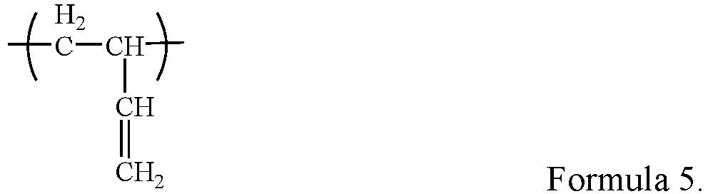
- The inventors found that the ratio between the first, second and third monomeric units may have an effect on the dispersing effect of the dispersant, which in turn affects the flow, viscosity and filtration performance of the positive electrode slurry and may also have an effect on the battery performance.
- In some embodiments, with respect to a total mass of the polymer, a mass percentage content of the first monomeric unit is M1, with M1 being 10%-55% (e.g. 10%, 15%, 20%, 25%, 30%, 32%, 35%, 40%, 45%, 50%, or 55%), optionally 25%-55%. The mass percentage content of M1 affects the solubility of the polymer and brittleness of the electrode plate. If the mass percentage content of M1 exceeds 55%, it may lead to poor dispersion and/or poor electrode plate brittleness, and if the mass percentage content of M1 is below 10%, the polymer becomes less soluble in the solvent (e.g., NMP), which in turn makes the slurry inhomogeneous.
- In some embodiments, with respect to the total mass of the polymer, a mass percentage content of the second monomeric unit is M2, with M2 being 40%-80% (e.g. 40%, 45%, 50%, 55%, 58%, 60%, 64%, 65%, 68%, 70%, 71%, 75%, or 80%), optionally 50%-70%. The mass percentage content of M2 affects the swelling of the polymer, the mass percentage content of M2 in the range of 40%-80% can ensure the weak polarity of the polymer and a better effect as a dispersant.
- In some embodiments, with respect to the total mass of the polymer, the mass percentage content of the third monomeric unit is M3, with M3 being 0%-10% (e.g., 0.001%, 0.005%, 0.01%, 0.05%, 0.1%, 0.3%, 0.4%, 0.5%, 1%, 1.3%, 1.8%, 2%, 3%, 3.8%, 4%, 5%, 5.2%, 6%, 7%, 8%, 9%, or 10%), optionally 0.001%-2%. The mass percentage content of M3 affects the solubility of the polymer and the bonding with the positive electrode current collector (e.g., aluminum foil). If the percentage of M3 is too low, the bonding of the slurry is poor, and if the mass percentage content of M3 is too high, the polymer tends to dissolve in the electrolyte and affects the battery performance.
- In some embodiments, M3/(M2+M3) is 0%-5% (e.g., 0.001%, 0.005%, 0.01%, 0.05%, 0.1%, 0.5%, 1%, 2%, 3%, 4%, or 5%), optionally 0.001%-1%.
- In some embodiments, the polymer is a random copolymer.
- In some embodiments, the polymer is hydrogenated nitrile butadiene rubber.
- Nitrile butadiene rubber (NBR) is a random copolymer made by polymerizing acrylonitrile with butadiene monomers (e.g. emulsion polymerization), and its structural general formula is:

- In NBR, the linkage of butadiene (B) and acrylonitrile (A) links is generally BAB, BBA or ABB, and ABA and BBB ternary groups, but with the increase of acrylonitrile content, there are also those who present as a AABAA quintuple linkage, and even become bulk polymers of acrylonitrile. In NBR, the sequence distribution of butadiene is mainly trans-1,4 structure, and its microstructure is related to the polymerization conditions. High polymerization temperatures decrease the trans-1,4 structure and increase the cis-1,4 and 1,2- structures.
- Hydrogenated butadiene nitrile rubber (HNBR) is the product obtained by hydrogenation and saturation of the carbon-carbon double bond in the molecular chain of nitrile rubber, so it is also called highly saturated nitrile rubber. The chemical formula of hydrogenated nitrile butadiene rubber is as follows:

- Due to its weak polarity and good affinity with carbon-containing materials, HNBR can act on the particle surface of positive electrode active materials (especially carbon-containing positive electrode active materials) and avoid inter-particle agglomeration through steric hindrance, while HNBR also has high strength and low glass transition temperature, which can improve the flexibility of the electrode plate.
- In some embodiments, the polymer has a weight average molar mass of 50,000-500,000 (e.g., 50,000, 60,000, 70,000, 80,000, 90,000, 100,000, 150,000, 200,000, 250,000, 300,000, 350,000, 400,000, 450,000, or 500,000), optionally 150,000-350,000. When the molar mass of the polymer is lower than 50,000, the film-forming property of the slurry is poor, and it is viscoelastic in the positive electrode, and the electrode plate is prone to sticking to the roller when cold pressed; while when the molar mass of the polymer is larger, the solubility of the polymer becomes poor, which is not conducive to the dispersion of the slurry.
- The dispersant hydrogenated nitrile butadiene rubber absorbs and swells more in the electrolyte and may affect the room-temperature direct current resistance (DCR) when added in excessive amounts. In some embodiments, with respect to a total mass of the positive electrode active material, the mass percentage of the dispersant is X1, with X1 being 0.05%-1% (e.g., 0.05%, 0.1%, 0.2%, 0.25%, 0.3%, 0.4%, 0.5%, 0.6%, 0.7%, 0.8%, 0.9%, or 1%), optionally 0.1%-0.5%. When X1 is 0.05%-1%, it can provide good dispersion effect, at the same time can avoid too much dispersant addition to affect the room-temperature DCR and influence the energy density of the battery.
- In some cases, the positive electrode active material has a poor wettability in NMP (N-methylpyrrolidone) and in turn the slurry stability is poor, as evidenced by low solid content of the slurry, decrease in viscosity after placement, etc., which in turn cannot be used properly. The inventors found that functional groups containing N (such as -CN/-NH2-/-N-, etc.), oxygen (such as -C=O/-COOH/-COOR/epoxy, etc.), or benzene rings have a better affinity for positive electrode active materials (especially those with a highly graphitized carbon coating layer on the surface and with a microporous structure), and small-molecule infiltrant containing these functional groups can effectively improve the wettability of the positive electrode active material in solvents (e.g., N-methylpyrrolidone).
- In some embodiments, the positive electrode active material composition further includes an infiltrant, the infiltrant has a surface tension of 20 mN/m-40 mN/m, and the molecular structure of the infiltrant includes at least one (e.g., two or more) of the following functional groups: -CN, -NH2, -NH-, -N-, -OH, -C=O, -COO-, -C(=O)-O- C(=O)-, epoxy group, and phenyl group. The surface tension of the infiltrant can be obtained using a surface tension meter following the measuring methods already known in the art.
- An example measuring method can be the platinum plate method, which is based on the principle that when the sensing platinum plate is immersed into the measured liquid, the surface tension around the platinum plate will be affected, and the surface tension of the liquid will pull the platinum plate down as far as possible. When the surface tension of the liquid and other related forces and the equilibrium force reach an equilibrium, the immersion of the sensing platinum plate in the liquid will stop. At this point, the balance sensor of the instrument measures the immersion depth and translates it into a surface tension value of the liquid.
- In the specific testing process, the testing steps of the platinum plate method are: (1) gradually immersing the platinum plate into a liquid; (2) sensing the equilibrium value by the sensor in the state of being immersed beneath the liquid surface; (3) converting the sensed equilibrium value into the surface tension value and displaying the value.
- The surface tension is calculated as follows:


-
- m: Weight of platinum plate
- g: Gravity (9.8 N/ Kg)
- L : Perimeter of the platinum plate
- γ : Surface tension of the liquid
- θ : Contact angle between liquid and platinum plate
- s : Cross-sectional area of platinum plate
- h : Depth of immersion of the platinum plate
- ρ : Density of the liquid
-
FIG. 1 exemplarily shows the measurement device and measurement principle of the platinum plate method. - In some embodiments, the infiltrant includes one or more selected from small-molecule organic solvents and low-molecular-weight polymers.
- The small-molecule organic solvent includes one or more selected from alcoholic amines, alcoholic compounds, nitrile compounds, optionally, the alcoholic amines have a carbon atom number of 1-16, optionally 2-6; for example, isopropanolamine, 2-amino-2methyl-1-propanol;
- The low-molecular-weight polymer includes one or more selected from maleic anhydride-styrene copolymers, polyvinylpyrrolidone, polysiloxanes, optionally, the low-molecular-weight polymer has a weight average molar mass of 6000 or less, such as 70-6000 (e.g., 70-100, 100-500, 500-1000, 1000-2000, 2000-3000, 3000-4000, 4000-5000, or 5000-6000), optionally 3000-6000.
- In some embodiments, with respect to the total mass of the positive electrode active material, the mass percentage content of the infiltrant is X2, with X2 being 0.05%-2% (e.g., 0.05%, 0.1%, 0.2%, 0.3%, 0.4%, 0.5%, 0.6%, 0.7%, 0.8%, 0.9%, 1%, 1.1%, 1.2%, 1.3%, 1.4%, 1.5%, 1.6%, 1.7%, 1.8%, 1.9%, or 2%), and optionally 0.2%-0.8%. When X2 is 0.05%-2%, it can provide a good infiltration effect, but also avoid too much infiltrant addition that can affect the stability of the positive electrode or electrolyte or affect the performance of the battery (e.g. cycling performance).
- In some embodiments, X1/X2 is 0.05-20 (e.g., 0.05, 0.1, 0.2, 0.3, 0.4, 0.5, 0.6, 0.7, 0.8, 0.9, 1, 1.1, 1.2, 1.3, 1.4, 1.5, 1.6, 1.7, 1.8, 1.9, 2, 3, 4, 5, 10, 15, or 20), optionally 0.1-1, further 0.3-0.8. When the ratio of the dispersant to the infiltrant is within the above range, the positive electrode slurry has lower viscosity and better flowability and filterability.
- The inventors of this application found in actual operation that the manganese exsolution from the lithium manganese phosphate positive electrode active material is relatively serious during intensive charging and discharging process. Although there are attempts in the existing technology to coat lithium iron phosphate on lithium manganese phosphate so as to reduce the interfacial side reactions, such coating cannot prevent the migration of exsolved manganese into the electrolyte. After the exsolved manganese migrates to the negative electrode, it is reduced to manganese metal. The resulting manganese metal is equivalent to a "catalyst" that catalyzes the decomposition of the SEI film (solid electrolyte interphase) on the positive electrode surface, and the resulting by-products are partly gas, which can easily lead to the expansion of the battery and affect the safety performance of the secondary battery; the other part is deposited on the surface of the negative electrode, which obstructs the passage of lithium ions to and from the negative electrode, causing an increase in the impedance of the secondary battery and affecting the kinetic performance of the battery. In addition, to replace the lost SEI film, the electrolyte and the active lithium inside the cell are continuously consumed, which brings irreversible effects on the capacity retention of the secondary cell.
- After extensive research, the inventors found that for lithium manganese phosphate positive electrode active materials, the problems of severe manganese exsolution and high surface reactivity may be caused by the Jahn-Teller effect of Mn3+ and the change of Li+ channel size after delithiation. For this reason, the inventors modified lithium manganese phosphate to obtain a positive electrode active material that can significantly reduce the manganese exsolution and reduce the lattice change rate, and thus has good cycling performance, high temperature storage performance and safety performance.
- The present application provides a positive electrode active material having a core-shell structure including a core and a shell coating the core,
- the core includes Li1+xMn1-yAyP1-zRzO4, x = -0.100-0.100, for example x may be 0.006, 0.004, 0.003, 0.002, 0.001, 0, -0.001, -0.003, -0.004, -0.005, -0.006, -0.007, -0.008, -0.009, - 0.10; y = 0.001-0.500, or example y may be 0.1, 0.2, 0.25, 0.3, 0.35, 0.4, 0.45; and z = 0.001-0.100, for example z may be 0.001, 0.002, 0.003, 0.004, 0.005, 0.006, 0.007, 0.008, 0.009, 0.1; the A is one or more selected from Zn, Al, Na, K, Mg, Mo, W, Ti, V, Zr, Fe, Ni, Co, Ga, Sn, Sb, Nb, and Ge, optionally from Fe, Ti, V, Ni, Co and Mg, the R is one or more selected from B, Si, N and S;
- the shell including a first coating layer coating the core and a second coating layer coating the first coating layer, where,
- the first coating layer includes a pyrophosphate MP2O7 and a phosphate XPO4, the M and X are each independently one or more selected from Li, Fe, Ni, Mg, Co, Cu, Zn, Ti, Ag, Zr, Nb, or Al;
- the second coating layer including carbon.
- Unless otherwise stated, in the above chemical formula, when A is more than two elements, the above limitation for the range of y values is not only for the stoichiometric number of each element as A, but also for the sum of the stoichiometric numbers of each element as A. For example, when A is more than two elements A1 and A2 ......An, the stoichiometric numbers y1 and y2 ......yn of each of A1 and A2 ......An must each fall within the range of values of y defined in this application, and the sum of y1 and y2 ......yn must also fall within the range of the value of y defined in this application. Similarly, in the case where R is more than two elements, the limits of the numerical range of the stoichiometric number of R in this application also have the above meaning.
- The lithium manganese phosphate positive electrode active material of this application is a core-shell structure with two coating layers, and the core includes Li1+xMn1-yAyP1-zRzO4, element A doped at the manganese site of lithium manganese phosphate in the core helps reduce the lattice change rate of lithium manganese phosphate during intercalation and deintercalation of lithium, improves the structural stability of the lithium manganese phosphate positive electrode material, greatly reduces manganese exsolution and reduces the oxygen activity on the particle surface. Element R doped at the phosphorus site helps the ease of Mn-O bond length change, thus reducing the lithium-ion migration barrier, promoting lithium-ion migration and improving the rate performance of the secondary battery.
- The first coating layer of the positive electrode active material of this application includes pyrophosphate and phosphate. Due to the high migration potential of transition metal in pyrophosphate (>1 eV), it can effectively inhibit the exsolution of transition metal. And phosphate has excellent ability to conduct lithium ions and can reduce the surface tramp lithium content. In addition, the second coating layer is a carbon layer, which can effectively improve the electrical conductivity and desolvation ability of LiMnPO4. In addition, the "barrier" effect of the second coating layer can further prevent the migration of manganese ions into the electrolyte and reduce the corrosion of the active material by the electrolyte.
- Therefore, this application can effectively inhibit the Mn exsolution in the process of intercalation and deintercalation of lithium, by specific elemental doping and surface coating of lithium manganese phosphate, and at the same time promote the migration of lithium ions, thus improving the multiplicity performance of the battery and improving the cycle performance and high-temperature performance of the secondary battery.
- It should be noted that by comparing the XRD spectra of LiMnPO4 before and after doping in this application, it can be seen that the positions of the main characteristic peaks of the positive electrode active material in this application are basically the same as those of LiMnPO4 before doping, indicating that the doped lithium manganese phosphate positive electrode active material has no impurity phase and the improvement of the secondary battery performance is mainly from the elemental doping rather than caused by the impurity phase.
- In some embodiments, optionally, the phosphate of the first coating layer has a crystal plane spacing of 0.345-0.358 nm and an angle of 24.25°-26.45° in the crystal direction (111); the pyrophosphate of the first coating layer has a crystal plane spacing of 0.293-0.326 nm and an angle of 26.41°-32.57° in the crystal direction (111).
- When the crystal plane spacing of phosphate and pyrophosphate in the first coating layer and the angle of crystal direction (111) are in the above range, the impurity phase in the coating layer can be effectively avoided, thus enhancing the gram capacity, cycling performance and rate performance of the material.
- In some embodiments, optionally, the ratio of y to 1-y in the core is from 1:10 to 10:1, optionally from 1:4 to 1:1. Here y denotes the sum of the stoichiometric numbers of the Mn-site doping elements. The energy density and cycling performance of the positive electrode active material can be further improved when the above conditions are met.
- In some embodiments, optionally, the ratio of z to 1-z in the core is from 1:9 to 1:999, optionally from 1:499 to 1:249. y herein denotes the sum of the stoichiometric numbers of the P-site doping elements. The energy density and cycling performance of the positive electrode active material can be further improved when the above conditions are met.
- In some embodiments, optionally, the first coating layer has a coating amount of greater than 0 wt% and less than or equal to 7 wt%, optionally 4-5.6 wt%, with respect to a weight of the core.
- When the amount of the first coating layer is within the above range, it can further inhibit the manganese exsolution while further promoting the lithium-ion transport. And it can effectively avoid the following situations: if the coating amount of the first coating layer is too small, it may lead to insufficient inhibition of manganese exsolution by pyrophosphate, while the improvement of lithium-ion transport performance is not significant; if the coating amount of the first coating layer is too large, it may lead to too thick coating layer, increase the impedance of the battery, and affect the kinetic performance of the battery.
- In some embodiments, optionally, the weight ratio of pyrophosphate to phosphate in the first coating layer is 1:3 to 3:1, optionally 1:3 to 1:1.
- The proper ratio between pyrophosphate and phosphate can help to fully utilize the synergistic effect of the two. And it can effectively avoid the following situations: if there is too much pyrophosphate and too little phosphate, it may lead to an increase in cell impedance; if there is too much phosphate and too little pyrophosphate, the effect of inhibiting manganese exsolution is not significant.
- In some embodiments, optionally, the pyrophosphate and phosphate each have a crystallinity of 10% to 100%, optionally 50% to 100%, independently.
- In the first coating layer of the lithium manganese phosphate positive electrode active material of the present application, pyrophosphate and phosphate with a certain degree of crystallinity are conducive to maintaining the structural stability of the first coating layer and reducing lattice defects. On the one hand, this is conducive to fully utilizing pyrophosphate in hindering the dissolution of manganese, and on the other hand, it is also conducive to the phosphate in reducing the surface lithium content and the valence of surface oxygen, thus reducing the interfacial side reactions between the positive electrode material and electrolyte, reducing the consumption of electrolyte and improving the cycle performance and safety performance of the battery.
- It is to be noted that in the present application, the crystallinity of the pyrophosphate and phosphate may be adjusted, for example, by adjusting the process conditions of the sintering process such as sintering temperature, sintering time, etc. The crystallinity of the pyrophosphates and phosphates can be measured by methods known in the art, for example by X-ray diffraction, density methods, infrared spectroscopy, differential scanning calorimetry and nuclear magnetic resonance absorption methods.
- In some embodiments, optionally, the second coating layer has a coating amount of greater than 0 wt% and less than or equal to 6 wt%, optionally 3-5 wt%, with respect to a weight of the core.
- As the second coating layer, the carbon layer can play a "barrier" function to avoid the direct contact between the positive electrode active material and the electrolyte, thus reducing the corrosion of the electrolyte on the active material and improving the safety performance of the battery under high temperature. On the other hand, it has a strong electrical conductivity, which can reduce the internal resistance of the battery and thus improve the kinetic performance of the battery. However, because of the low gram capacity of carbon materials, the overall gram capacity of the positive electrode active material may be reduced when the amount of the second coating layer is too large. Therefore, when the amount of the second coating layer is in the above-mentioned range, it can further improve the kinetic performance and safety performance of the battery without sacrificing the gram capacity of the positive electrode active material.
- In some embodiments, optionally, the A is at least two selected from Fe, Ti, V, Ni, Co, and Mg.
- The simultaneous doping of two or more of the above elements in the manganese sites of the lithium manganese phosphate positive electrode active material is conducive to enhancing the doping effect, further reducing the lattice change rate on the one hand, thereby inhibiting the exsolution of manganese and reducing the consumption of electrolyte and active lithium, and on the other hand, further reducing the surface oxygen activity and reducing the interfacial side reactions between the positive electrode active material and electrolyte, thereby improving the cycling performance and high-temperature storage performance of the battery.
- In some embodiments, optionally, the positive electrode active material has a Li/Mn-antisite defect concentration of 4% or less, optionally 2% or less.
- In the positive electrode active material of this application, the Li/Mn-antisite defect refers to the interchange of the positions of Li+ and Mn2+ in the LiMnPO4 lattice. Since the Li+ transport channel is a one-dimensional channel, Mn2+ is difficult to migrate in the Li+ transport channel, therefore, the Mn2+ of the anti-site defect will hinder the Li+ transport. The gram capacity and rate performance of LiMnPO4 can be improved by controlling the concentration of Li/Mn-antisite defects at low levels. In this application, the antisite-defect concentration can be determined, for example, according to JIS K 0131-1996.
- In some embodiments, optionally, the positive electrode active material has a lattice change rate of 6% or less, optionally 4% or less.
- The process of intercalation and deintercalation of lithium in LiMnPO4 is a two-phase reaction. The interfacial stress of the two phases is determined by the magnitude of the lattice rate of change, and the smaller the lattice rate of change, the lower the interfacial stress and the easier the Li+ transport. Therefore, reducing the lattice rate of change of the core will be beneficial to enhance the transport capacity of Li+ and thus improve the rate performance of the secondary battery.
- In some embodiments, optionally, the positive electrode active material has a buckling average discharge voltage of 3.5 V or more and a discharge gram capacity of 140 mAh/g or more; optionally, the average discharge voltage is 3.6 V or more and the discharge gram capacity is 145 mAh/g or more.
- Although the average discharge voltage of undoped LiMnPO4 is above 4.0 V, its discharge gram capacity is low, usually less than 120 mAh/g, and therefore, the energy density is low; adjusting the lattice change rate by doping can make its discharge gram capacity increase significantly, and the overall energy density has a significant increase with a slight decrease in the average discharge voltage.
- In some embodiments, optionally, the positive electrode active material has a surface oxygen valency of -1.88 or less, optionally -1.98 to -1.88.
- This is due to the fact that the higher the valence state of oxygen in a compound, the stronger its electron-gaining ability, i.e., the stronger the oxidation. In the lithium manganese phosphate positive electrode active material of this application, by controlling the surface valence state of oxygen at a lower level, the reactivity on the surface of the positive electrode material can be reduced and the interfacial side reactions between the positive electrode material and the electrolyte can be reduced, thus improving the cycle performance and high temperature storage performance of the secondary battery.
- In some embodiments, optionally, the positive electrode active material has a compaction density at 3 tons (T) of 2.0 g/cm3 or more, optionally 2.2 g/cm3 or more.
- The higher the compaction density of the positive electrode active material, i.e., the higher the weight per unit volume of the active material, will be more beneficial to improve the volumetric energy density of the battery. In this application, the compaction density can be measured, for example, according to GB/T 24533-2009.
- In some embodiments, the positive electrode active material is prepared by a method including the steps of:
- a step of providing a core material: the core includes Li1+xMn1-yAyP1-zRzO4, where x=-0.100-0.100, y=0.001-0.500, z=0.001-0.100, the A is one or more selected from Zn, Al, Na, K, Mg, Mo, W, Ti, V, Zr, Fe, Ni, Co, Ga, Sn, Sb, Nb, and Ge, optionally one or more of Fe, Ti, V, Ni, Co and Mg, the R is one or more selected from B, Si, N and S;
- coating step: MP2O7 powder and XPO4 suspension containing a source of carbon are provided, the core material, the MP2O7 powder are added to the XPO4 suspension containing a source of carbon and mixed, and sintered to obtain a positive electrode active material, wherein the M and X are each independently one or more selected from Li, Fe, Ni, Mg, Co, Cu, Zn, Ti, Ag, Zr, Nb or Al;
- The positive electrode active material has a core-shell structure including a core and a shell coating the core, shell including a first coating layer enveloping the core and a second coating layer enveloping the first coating layer, the first coating layer includes pyrophosphate MP2O7 and phosphate XPO4, the second coating layer including carbon.
- In some embodiments, the step of providing the core material includes the steps of:
- Step (1): mixing a manganese source, a source of element A and an acid in a container and stirring to obtain manganese salt particles doped with element A;
- Step (2): mixing the manganese salt particles doped with element with a source of lithium, a source of phosphorus and a source of element R in a solvent to obtain a slurry, and sintering under inert gas atmosphere protection to obtain lithium manganese phosphate doped with element A and element R, where the lithium manganese phosphate doped with element A and element R is Li1+xMn1-yAyP1-zRzO4, where x = -0.100-0.100, y = 0.001-0.500, z=0.001-0.100, the A is one or more selected from Zn, Al, Na, K, Mg, Mo, W, Ti, V, Zr, Fe, Ni, Co, Ga, Sn, Sb, Nb and Ge, optionally one or more of Fe, Ti, V, Ni, Co and Mg, the R is one or more selected from B, Si, N and S.
- In some embodiments, the step (1) is performed at a temperature of 20-120°C, optionally 25-80°C (e.g., 80°C).
- In some embodiments, the stirring in the step (1) is performed at 500-700 rpm (e.g., 600 rpm) for 60-420 minutes, optionally 120-360 minutes (e.g., 360 minutes).
- In some embodiments, the source of element A is one or more selected from the monomers of element A, sulfates of element A, halides of element A, nitrates of element A, organic acid salts of element A, oxides of element A, or hydroxides of element A; and/or, the source of element R is one or more selected from the monomers of element R, sulfates of element R, halides of element R, nitrates of element R, organic acid salts of element R, oxides of element R, or hydroxides of element R and inorganic acids of element R.
- In some embodiments, the MP2O7 powder is prepared by:
adding a source of element M and a source of phosphorus a solvent to obtain a mixture, adjusting the pH of the mixture to 4-6 (e.g., 5), stirring and fully reacting, and then obtaining the powder by drying and sintering, where M is one or more selected from Li, Fe, Ni, Mg, Co, Cu, Zn, Ti, Ag, Zr, Nb, or Al. In some embodiments, the drying step is drying at 100-300°C (e.g. 120°C), optionally 150-200°C for 4-8 hrs (e.g. 4 hrs). In some embodiments, the sintering step is sintering at 500-800°C (e.g., 650°C), optionally 650-800°C, under an inert gas atmosphere for 4-10 hrs (e.g. 8 hrs). - In some embodiments, the sintering temperature in the coating step is 500-800°C (e.g., 700°C) and the sintering time is 4-10 hrs (e.g., 6 hrs).
- A second aspect of the present application provides a positive electrode slurry including the
- positive electrode active material composition of the first aspect of the present application; optionally
- also including one or more of a solvent, a positive electrode conductive agent, and a positive electrode binder.
- In some embodiments, the solvent includes N-methylpyrrolidone (NMP).
- In some embodiments, the positive electrode binder includes one or more selected from polyvinylidene fluoride (PVDF), polytetrafluoroethylene (PTFE), vinylidene fluoride-tetrafluoroethylene-propylene terpolymers, vinylidene fluoride-hexafluoropropylene-tetrafluoroethylene terpolymers, vinylidene fluoride-hexafluoropropylene copolymers, and fluorinated acrylate resin.
- In some embodiments, the positive electrode conductive agent includes one or more selected from superconducting carbon, acetylene black, carbon black, Ketjen black, carbon dots, carbon nanotubes, graphene, and carbon nanofibers.
- In this application, the solid content of the positive electrode slurry can be enhanced, and/or the viscosity of the positive electrode slurry can be reduced, by selecting a suitable dispersant and/or an infiltrant.
- In some embodiments, the positive electrode slurry has a solid content of 40%-70% (e.g., 40%, 45%, 50%, 55%, 58%, 60%, 64%, 65%, 68%, or 70%), optionally 55%-65%.
- In some embodiments, the positive electrode slurry has a viscosity of3,000mpa.s-50,000mpa.s at 20°C (e.g. 3000 mpa.s, 4000 mpa.s, 5000 mpa.s, 6000 mpa.s, 7000 mpa.s, 8000 mpa.s, 9000 mpa.s, 10,000 mpa.s, 11000 mpa.s, 12000 mpa.s, 13000 mpa.s, 14000 mpa.s, 15000 mpa.s, 16000 mpa.s, 17000 mpa.s, 18000 mpa.s, 19000 mpa.s, 20000 mpa.s, 30000 mpa.s, 40000 mpa.s, or 50000 mpa.s), and optionally 10,000 mpa.s-20,000 mpa.s.
- A third aspect of the present application provides a positive electrode plate including a positive electrode current collector and a positive electrode film layer provided on at least one surface of the positive electrode current collector, the positive electrode film layer includes the positive electrode active material composition of the first aspect of the present application or is prepared by coating the positive electrode slurry of the second aspect of the present application. The positive electrode film layer may be disposed on one surface of the positive electrode current collector, or may be provided on both surfaces of the positive electrode current collector.
- In some embodiments, with respect to a total mass of the positive electrode film layer,
- the mass percentage content of the positive electrode active material is W1, with W1 being 90%-99.5% (e.g., 90%, 91%, 92%, 93%, 94%, 95%, 96%, 97%, 98%, 99%, or 99.5%), optionally 95% -99%; and/or
- in some embodiments, the dispersant has a mass percentage content of W2, with W2 being 1% or less (e.g., 0.001%, 0.005%, 0.01%, 0.05%, 0.1%, 0.2%, 0.3%, 0.4%, 0.5%, or 1%), optionally 0.1%-0.5%; and/or
- in some embodiments, the infiltrant has a mass percentage content of W3, with W3 being 2% or less (e.g., 0.001%, 0.005%, 0.01%, 0.05%, 0.1%, 0.2%, 0.3%, 0.4%, 0.5%, 1%, or 2%), optionally 0.1%-0.5%; and/or
- in some embodiments, the positive electrode binder has a mass percentage content of W4, with W4 being 5.5% or less (e.g., 0.001%, 0.005%, 0.01%, 0.05%, 0.1%, 0.5%, 1%, 1.2%, 1.5%, 2%, 2.3%, 2.5%, 2.7%, 3%, 4%, 5%, or 5.5%), optionally 1% to 3%; and/or,
- in some embodiments, the positive electrode conductive agent has a mass percentage content of W5, with W5 being 2.5% or less (e.g., 0.001%, 0.005%, 0.01%, 0.05%, 0.1%, 0.2%, 0.3%, 0.4%, 0.5%, 0.6%, 0.7%, 0.8%, 0.9%, 1%, 2%, or 2.5%), optionally 0.1%-1%.
- In some embodiments, the positive electrode current collector may be a metal foil or a composite current collector. For example, as a metal foil, an aluminum foil may be used. The composite current collector may include a base layer of high polymer material and a metal layer formed on at least one surface of the base layer of high polymer material. The composite current collector may be formed by forming a metal material (aluminum, an aluminum alloy, nickel, a nickel alloy, titanium, a titanium alloy, silver and a silver alloy, etc.) on a high polymer base material (such as a base material of polypropylene (PP), polyethylene terephthalate (PET), polybutylene terephthalate (PBT), polystyrene (PS), polyethylene (PE), etc.).
- In some embodiments, one or more under-coating layers between the positive electrode current collector and the positive electrode film layer are also provided to increase the bond between the positive electrode current collector and the positive electrode film layer. In some embodiments, the under-coating layer includes a polyacrylic acid-acrylate copolymer (e.g., polyacrylic acid-acrylate copolymer having a weight average molar mass of 300,000-350,000) and a conductive agent (e.g., conductive carbon black (Super P)), the weight ratio between the two may be 60:40-40:60. An exemplary methods of preparation includes: dissolving/dispersing the polyacrylic acid-acrylate copolymer and the conductive agent in deionized water to form a under-coating slurry; applying the under-coating slurry to one or both sides of the positive electrode current collector (e.g., aluminum foil) and drying to obtain a positive electrode current collector with a conductive under-coating layer. In some embodiments, the thickness of the under-coating layer is 1-5 µm.
- In some embodiments, the positive electrode material layer further optionally includes a binder. The type and content of the conductive agent as well as the binder are not specifically limited and can be selected according to actual needs. As an example, the binder may include at least one of polyvinylidene fluoride (PVDF), polytetrafluoroethylene (PTFE), vinylidene fluoride-tetrafluoroethylene-propylene terpolymers, vinylidene fluoride-hexafluoropropylene-tetrafluoroethylene terpolymers, vinylidene fluoride-hexafluoropropylene copolymers, and fluorinated acrylate resin.
- In some embodiments, the positive electrode material layer may further optionally include a conductive agent. As an example, the conductive agent may include at least one of superconducting carbon, acetylene black, carbon black, Ketjen black, carbon dots, carbon nanotubes, graphene, and carbon nanofibers.
- In some embodiments, the positive electrode plate can be prepared by the following method: dispersing the positive electrode active material, the conductive agent, the binder and any other components in a solvent (e.g., N-methylpyrrolidone) to form a positive electrode slurry; coating the positive electrode slurry on the positive electrode current collector, and after drying and cold pressing, the positive electrode plate can be obtained. Optionally, the coating method is selected from lifting method, film- pulling method, electrostatic spraying method and spin coating method.
- A fourth aspect of the present application provides a secondary battery including the positive electrode plate of the third aspect of the present application.
- In the secondary battery of the present application, the negative electrode plate may include a negative electrode current collector and a negative electrode material layer provided on the negative electrode current collector and including a negative electrode active material, the negative electrode material layer may be provided on one surface of the negative electrode current collector or on both surfaces of the negative electrode current collector.
- In some embodiments, the negative electrode current collector may be a metal foil or a composite current collector. For example, as a metal foil, a copper foil may be used. The composite current collector may include a high-polymer-material base layer and a metal layer formed on at least one surface of the high-polymer-material base layer. The composite current collector can be formed by forming a metal material (copper, a copper alloy, nickel, a nickel alloy, titanium, a titanium alloy, silver and a silver alloy, etc.) on a high-polymer base material (such as a base material of polypropylene (PP), polyethylene terephthalate (PET), polybutylene terephthalate (PBT), polystyrene (PS), polyethylene (PE), etc.).
- In some embodiments, the negative electrode active material may be a negative electrode active material for batteries that is well known in the art. As examples, the negative electrode active material may include at least one of the following materials: graphite (e.g., artificial graphite, natural graphite), soft carbon, hard carbon, intermediate phase carbon microspheres, carbon fibers, carbon nanotubes, silicon-based materials, tin-based materials, and lithium titanate. The silicon-based materials may be at least one selected from monolithic silicon, silicon oxide, silicon carbon complexes, silicon nitrogen complexes, and silicon alloys. The tin-based materials can be at least one selected from monolithic tin, tin-oxygen compounds and tin alloys. However, the present application is not limited to these materials, and other conventional materials that can be used as battery negative electrode active materials may also be used. These negative electrode active materials can be used alone or in combination of two or more.
- In some embodiments, the negative electrode film layer further optionally includes a binder. The binder may be at least one selected from styrene butadiene rubber (SBR), polyacrylic acid (PAA), sodium polyacrylate (PAAS), polyacrylamide (PAM), polyvinyl alcohol (PVA), sodium alginate (SA), polymethacrylic acid (PMAA), and carboxymethyl chitosan (CMCS).
- In some embodiments, the negative electrode film layer may further optionally include a conductive agent. The conductive agent may be at least one selected from superconducting carbon, acetylene black, carbon black, Ketjen black, carbon dots, carbon nanotubes, graphene, and carbon nanofibers.
- In some embodiments, the negative electrode material layer includes the negative electrode active material of artificial graphite, the conductive agent of acetylene black, and the binder of styrene-butadiene rubber (SBR).
- In some embodiments, the negative electrode material layer optionally also includes other additives, such as thickeners (e.g., sodium carboxymethyl cellulose (CMC-Na)), etc.
- In some embodiments, the negative electrode plate may be prepared by: dispersing the above components for preparing a negative electrode plate, such as the negative electrode active material, the conductive agent, the binder and any other components in a solvent (e.g., deionized water) to form a negative electrode slurry; coating the negative electrode slurry on the negative electrode current collector, and after drying and cold pressing, the negative electrode plate can be obtained.
- In the secondary battery of the present application, the separator is disposed between the positive electrode and negative electrode plates for separation. In this regard, the type of the separator is not specifically limited, and any well-known porous structure separator with good chemical stability and mechanical stability can be used. In some embodiments, the material of the separator may be at least one selected from glass fiber, nonwoven, polyethylene, polypropylene and polyvinylidene fluoride. The separator may be a single-layer membrane or a multi-layer composite membrane, without any particular limitation. Where the separator is a multi-layer composite membrane, the materials of the layers may be the same or different, with no particular limitations.
- The secondary battery of the present application may be prepared using conventional methods. In some embodiments, the positive electrode plate, the negative electrode plate, and the separator may be made into an electrode assembly by a winding process or a laminating process. An exemplary preparation method includes:
- Step 1: stacking a positive electrode plate, a separator and a negative electrode plate sequentially so that the separator is between the positive electrode and the negative electrode plates, and then winding to obtain the electrode assembly; and
- Step 2: placing the electrode assembly in a secondary battery casing, drying and injecting with electrolyte, and then the secondary battery is made after a chemical formation and resting process.
- In some embodiments, the secondary battery of the present application may include an outer packaging. The outer packaging may be used to encapsulate the above-mentioned electrode assembly and electrolyte.
- In some implementations, the outer packaging of the secondary battery may be a hard casing, such as a hard plastic casing, aluminum casing, steel casing, etc. The outer packaging of the secondary battery may also be a soft pack, such as a pouch-type soft pack. The material of the soft pack may be plastic, exemplarily polypropylene, polybutylene terephthalate, and polybutylene succinate.
- The shape of the secondary battery of the present application is not particularly limited, which may be cylindrical, square, or any other shape. For example,
FIG. 6 shows as an example asecondary battery 5 with a square structure. - In some embodiments, referring to
FIG. 7 , the outer packaging may include acasing 51 and atop cover assembly 53. wherein thecasing 51 may include a bottom plate and side plates connected to the bottom plate, the bottom plate and the side plates enclosing a receiving cavity. Thecasing 51 has an opening connected to the receiving cavity, and thetop cover assembly 53 can be provided over the opening to close the receiving cavity. The positive electrode plate, the negative electrode plate, and the separator may be wound or laminated to form anelectrode assembly 52, which is encapsulated in the receiving cavity. An electrolyte is infiltrated into theelectrode assembly 52. The number ofelectrode assemblies 52 contained in thesecondary battery 5 may be one or more, which may be selected by a person skilled in the art according to specific practical needs. - In some embodiments, the secondary battery can be assembled into a battery module, and the number of secondary batteries contained in the battery module can be one or more, with the specific number being selected by those skilled in the art based on the application and capacity of the battery module.
-
FIG. 4 shows, as an example, abattery module 4. Referring toFIG. 4 , in thebattery module 4, a plurality ofsecondary batteries 5 may be arranged sequentially along a length of thebattery module 4. Of course, they can also be arranged in any other way. Further, the plurality ofsecondary batteries 5 may be secured by fasteners. - Optionally, the
battery module 4 may also include a housing having an accommodating space in which a plurality ofsecondary batteries 5 are accommodated. - In some embodiments, the above battery modules may also be assembled into a battery pack, and the number of battery modules contained in the battery pack can be one or more, the specific number of which can be selected by a person skilled in the art according to the application and capacity of the battery pack.
-
FIGS. 5 and6 show, as an example, abattery pack 1. Referring toFIGS. 5 and6 , thebattery pack 1 may include a battery container and a plurality ofbattery modules 4 disposed in the battery container. the battery container includes anupper container body 2 and alower container body 3, and theupper container body 2 is able to be covered by thelower container body 3 and form an enclosed space for accommodating thebattery modules 4. A plurality ofbattery modules 4 can be arranged in the battery container in any manner. - Further, the present application provides an electric device, and the electric device includes the secondary battery, the battery module, or the battery pack provided in the present application. The secondary battery, the battery module, or the battery pack may be used as a power source for the electric device or may be used as an energy storage unit for the electric device. The electric device may be selected from, but not limited to, mobile devices (e.g., cell phones, laptops, etc.), electric vehicles (e.g., pure electric vehicles, hybrid electric vehicles, plug-in hybrid electric vehicles, electric bicycles, electric scooters, electric golf carts, electric trucks, etc.), electric trains, ships and satellites, energy storage systems, etc. As an electric device, the secondary battery, the battery module or the battery pack may be selected according to application needs.
-
FIG. 7 shows as an exemplary electric device. The electric device is a pure electric vehicle, a hybrid electric vehicle, or a plug-in hybrid electric vehicle, etc. To meet the high power and high energy density requirements of the secondary battery for this electric device, a battery pack or battery module may be used. - As another example the device may be a cell phone, tablet, laptop, etc. The device usually requires thinness and lightness and may employ a secondary battery as a power source.
- Hereinafter, examples of the present application are described. The examples described below are exemplary and are intended to explain the present application only and are not to be construed as limiting the present application. Where specific techniques or conditions are not indicated in the examples, the techniques or conditions described in the literature in the art or in accordance with the product specification are followed. Where the reagents or instruments used are not specified as manufacturers, they are conventional products that can be obtained commercially.
- The sources of raw materials used in examples of this application are as follows:
Name Chemical formula Manufacturers Specification Manganese carbonate MnCO3 Shandong West Asia Chemical Industry Co. 1Kg Lithium carbonate Li2CO3 Shandong West Asia Chemical Industry Co. 1Kg Magnesium carbonate MgCO3 Shandong West Asia Chemical Industry Co. 1Kg Zinc carbonate ZnCO3 Wuhan Xinru Chemical Co. 25Kg Ferrous carbonate FeCO3 Xi'an Lanzhiguang Fine Material Co. 1Kg Nickel Sulfate NiCO3 Shandong West Asia Chemical Industry Co. 1Kg Titanium sulfate Ti(SO4)2 Shandong West Asia Chemical Industry Co. 1Kg Cobalt Sulfate CoSO4 Xiamen Zhixin Chemical Co. 500g Vanadium dichloride VCl2 Shanghai Jinjinle Industrial Co. 1Kg Oxalic acid dihydrate C2H2O4 •2H2O Shanghai Jinjinle Industrial Co. 1Kg Ammonium dihydrogen phosphate NH4H2PO4 Shanghai Cheng Shao Biotechnology Co. 500g Sucrose C12H22O11 Shanghai Yuanye Biotechnology Co. 100g Sulfuric acid H2SO4 Shenzhen Haishian Biotechnology Co. Mass fraction 60% Nitric acid HNO3 Anhui Lingtian Fine Chemical Co. Mass fraction 60% Silicic acid H2SiO3 Shanghai Yuanye Biotechnology Co. 100g Boric acid H3BO3 Changzhou Qidi Chemical Co. 1Kg - Preparation of Fe, Co and V co-doped manganese oxalate: 689.5 g of manganese carbonate (as MnCOs, same below), 455.2 g of ferrous carbonate (as FeCOs, same below), 4.6 g of cobalt sulfate (as CoSO4, same below) and 4.9 g of vanadium dichloride (as VCl2, same below) were thoroughly mixed in a mixer for 6 hrs. The mixture was transferred to a reactor and 5 liters of deionized water and 1260.6 g of oxalic acid dihydrate (as C2H2O4.2H2O, the same below) were added. The reactor was heated to 80°C and stirred at 600 rpm for 6 hrs until the reaction was terminated (no bubbles were generated) to obtain a suspension of Fe, Co, V and S co-doped manganese oxalate. Then the suspension was filtered and the filter cake was dried at 120°C, after which it was ground to obtain Fe, Co and V co-doped manganese oxalate dihydrate particles with a median particle size Dv50 of 100 nm.
- Preparation of Fe, Co, V and S co-doped lithium manganese phosphate: the manganese oxalate particles dihydrate obtained in the previous step (1793.4 g), 369.0 g lithium carbonate (as Li2CO3, the same below), 1.6 g dilute sulfuric acid with a concentration of 60% (as 60% H2SO4, the same below) and 1148.9 g ammonium dihydrogen phosphate (as NH4H2PO4, the same below) were added to 20 liters of deionized water. The mixture was stirred for 10 hrs to evenly mix to obtain a slurry. The slurry was transferred to a spray drying equipment for spray drying granulation at a drying temperature of 250°C for 4 hrs to obtain powder. The above powder was sintered at 700°C for 4 hrs in a protective atmosphere of nitrogen (90 vol%) + hydrogen (10 vol%) to obtain 1572.1 g of Fe, Co, V and S co-doped lithium manganese phosphate.
- Preparation of lithium iron pyrophosphate powder: 4.77 g of lithium carbonate, 7.47 g of ferrous carbonate, 14.84 g of ammonium dihydrogen phosphate and 1.3 g of oxalic acid dihydrate were dissolved in 50 mL of deionized water. The pH of the mixture was 5, and the reaction mixture was stirred for 2 hrs to fully react. Then the reacted solution was heated up to 80°C and kept at this temperature for 4 hrs to obtain a suspension containing Li2FeP2O7, the suspension was filtered, washed with deionized water and dried at 120°C for 4 hrs to obtain a powder. The powder was sintered at 650°C under a nitrogen atmosphere for 8 hrs and naturally cooled to room temperature and then ground to obtain Li2FeP2O7 powder.
- Preparation of lithium iron phosphate suspension: 11.1 g of lithium carbonate, 34.8 g of ferrous carbonate, 34.5 g of ammonium dihydrogen phosphate, 1.3 g of oxalic acid dihydrate and 74.6 g of sucrose (as C12H22O11, same below) were dissolved in 150 mL of deionized water to obtain a mixture, and then stirred for 6 hrs to make the above mixture fully react. Then the reacted solution was heated up to 120°C and kept at this temperature for 6 hrs to obtain a suspension containing LiFePO4.
- 1572.1 g of the above Fe, Co, V and S co-doped lithium manganese phosphate and 15.72 g of the above lithium iron pyrophosphate (Li2FeP2O7) powder were added to the lithium iron phosphate (LiFePO4) suspension prepared in the previous step, stirred and mixed well, and then transferred to a vacuum oven and dried at 150°C for 6 hrs. The resulting product was then dispersed by sand grinding. After dispersion, the resulting product was sintered in a nitrogen atmosphere at 700°C for 6 hrs to obtain the target product of double-layer coated lithium manganese phosphate.
- The above-prepared double-layer coated lithium manganese phosphate positive electrode active material, conductive agent acetylene black, and binder polyvinylidene fluoride (PVDF) were added to N-methylpyrrolidone (NMP) in the ratio of 92:2.5:5.5 by weight, stirred and mixed well to obtain a positive electrode slurry. Then the positive electrode slurry was uniformly coated on an aluminum foil according to 0.280 g/1540.25 mm2, dried, cold pressed and slit to obtain a positive electrode plate.
- A negative electrode active substance of artificial graphite, hard carbon, conductive agent of acetylene black, a binder of styrene butadiene rubber (SBR), and a thickener of sodium carboxymethyl cellulose (CMC-Na) were dissolved in solvent deionized water according to the weight ratio of 90:5:2:2:1, mixed well and prepared into a negative electrode slurry. The negative electrode slurry was uniformly coated on a negative electrode current collector of copper foil according to 0.117 g/1540.25 mm2, and a negative electrode plate was obtained after drying, cold pressing and slitting.
- In an argon atmosphere glove box (H2O < 0.1 ppm, O2 < 0.1 ppm), as an organic solvent, ethylene carbonate (EC)/methylene carbonate (EMC) was mixed well in a volume ratio of 3/7, and 12.5wt% (with respect to a weight of the organic solvent) LiPF6 was added to dissolve in the above organic solvent and stirred well to obtain an electrolyte.
- Commercially available PP-PE copolymer microporous films with a thickness of 20 µm and an average pore size of 80 nm (from Tricor Electronics Technology, model 20) were used.
- The positive electrode plate, the separator and the negative electrode plate obtained above were stacked in order, so that separator was disposed between the positive electrode and negative electrode plates for isolation, and the bare battery was obtained by winding. The bare battery was placed in an outer packaging, filled with the above electrolyte and encapsulated to obtain a full battery (also referred to as "full cell" hereinafter).
- The above-prepared double-layer coated lithium manganese phosphate positive electrode active material, PVDF and acetylene black were added to NMP in a weight ratio of 90:5:5 and stirred in a drying room to make a slurry. The above slurry was coated on an aluminum foil, dried and cold pressed to form a positive electrode plate. The coating amount was 0.02 g/cm2, and the compacted density was 2.0 g/cm3.
- A lithium plate was used as the negative electrode, and a solution of 1 mol/L LiPF6 in ethylene carbonate (EC) + diethyl carbonate (DEC) + dimethyl carbonate (DMC) at a volumetric ratio of 1:1:1 was used as the electrolyte, which was assembled with the above prepared positive electrode plate in a button cell container to form a button battery (also referred to as "button cell" hereinafter).
- In the preparation of the co-doped lithium manganese phosphate core, the conditions for the preparation of the lithium manganese phosphate cores in Example 1-2 to Example 1-6 were the same as in Example 1-1 except that vanadium dichloride and cobalt sulfate were not used, and 463.4 g of ferrous carbonate, 1.6 g of 60% dilute sulfuric acid, 1148.9 g of ammonium dihydrogen phosphate, and 369.0 g of lithium carbonate were used.
- In addition, during the preparation of lithium iron pyrophosphate and lithium iron phosphate and the process of coating the first coating layer and the second coating layer, except that the amount of raw materials used was adjusted according to the ratio of the coating amount shown in Table 1 to the coating amount in Example 1-1, such that the amounts of Li2FeP2O7/LiFePO4 in Examples 1-2 to 1-6 were 12.6 g/37.7 g, 15.7 g/47.1 g, 18.8 g/56.5 g, 22.0/66.0 g and 25.1 g/75.4 g, respectively, and the amount of sucrose in Examples 1-2 to 1-6 was 37.3g, other conditions were the same as in Example 1-1.
- The conditions of Examples 1-7 to 1-10 were the same as those in Example 1-3 except that the amounts of sucrose were 74.6 g, 149.1 g, 186.4 g, and 223.7 g, respectively, so that the corresponding amounts of the carbon layer as the second coating layer were 31.4 g, 62.9 g, 78.6 g, and 94.3 g, respectively.
- The conditions of Examples 1-11 to 1-14 were the same as those in Example 1-7 except that the amounts of various raw materials were adjusted in the preparation of lithium iron pyrophosphate and lithium iron phosphate corresponding to the coating amounts shown in Table 1 so that the amounts of Li2FeP2O7/LiFePO4 were 23.6 g/39.3 g, 31.4 g/31.4 g, 39.3 g/23.6 g, and 47.2 g/15.7 g, respectively.
- The conditions of Example 1-15 were the same as those in Example 1-14 except that 492.80 g ZnCOs was used instead of ferrous carbonate in the preparation of the co-doped lithium manganese phosphate core.
- Except that 466.4 g of NiCO3, 5.0 g of zinc carbonate, and 7.2 g of titanium sulfate were used instead of ferrous carbonate during the preparation of the co-doped lithium manganese phosphate core in Example 1-16, 455.2 g of ferrous carbonate and 8.5 g of vanadium dichloride were used during the preparation of the co-doped lithium manganese phosphate core in Example 1-17, and 455.2 g of ferrous carbonate, 4.9 g of vanadium dichloride, and 2.5 g of magnesium carbonate were used during the preparation of the co-doped lithium manganese phosphate core in Example 1-18, other conditions in Examples 1-17 to 1-19 were the same as those in Example 1-7.
- Except that 369.4 g of lithium carbonate was used and 1.05 g of 60% dilute nitric acid was used instead of dilute sulfuric acid in the preparation of co-doped lithium manganese phosphate core in Example 1-19, and 369.7 g of lithium carbonate was used and 0.78 g of silicate was used instead of dilute sulfuric acid in the preparation of co-doped lithium manganese phosphate core in Examples 1-20, other conditions in Examples 1-19 to 1-20 were the same as those in Example 1-18.
- Except that 632.0 g of manganese carbonate, 463.30 g of ferrous carbonate, 30.5 g of vanadium dichloride, 21.0 g of magnesium carbonate, and 0.78 g of silicic acid were used in the preparation of co-doped lithium manganese phosphate core in Example 1-21, and 746.9 g of manganese carbonate, 289.6 g of ferrous carbonate, 60.9 g of vanadium dichloride, 42.1 g of magnesium carbonate, and 0.78 g of silicic acid were used in the preparation of the co-doped lithium phosphate core, in Example 1-22, other conditions in Examples 1-21 to 1-22 were the same as those in Example 1-20.
- Except that 804.6 g of manganese carbonate, 231.7 g of ferrous carbonate, 1156.2 g of ammonium dihydrogen phosphate, 1.2 g of boric acid (99.5% by mass fraction), and 370.8 g of lithium carbonate were used in the preparation of the co-doped lithium manganese phosphate core in Example 1-23; 862.1 g of manganese carbonate, 173.8 g of ferrous carbonate, 1155.1 g of ammonium dihydrogen phosphate, 1.86 g of boric acid (99.5% by mass), and 371.6 g of lithium carbonate were used in Example 1-24, other conditions in Examples 1-23 to 1-24 were the same as those in Example 1-22.
- Except that 370.1 g of lithium carbonate, 1.56 g of silicic acid, and 1147.7 g of ammonium dihydrogen phosphate were used in the preparation of the co-doped lithium manganese phosphate core in Example 1-25, other conditions in Example 1-25 were the same as those in Example 1-20.
- Except that 368.3 g of lithium carbonate, 4.9 g of dilute sulfuric acid with a mass fraction of 60%, 919.6 g of manganese carbonate, 224.8 g of ferrous carbonate, 3.7 g of vanadium dichloride, 2.5 g of magnesium carbonate, and 1146.8 g of ammonium dihydrogen phosphate were used in the preparation of the co-doped lithium manganese phosphate core in Example 1-26, other conditions in Example 1-26 were the same as those in Example 1-20.
- Except that 367.9 g of lithium carbonate, 6.5 g of dilute sulfuric acid at a concentration of 60%, and 1145.4 g of ammonium dihydrogen phosphate were used in the preparation of the co-doped lithium manganese phosphate core in Example 1-27, other conditions in Example 1-27 were the same as those in Example 1-20.
- Other conditions in Examples 1-28 to 1-33 were the same as those in Example 1-20, except that, in the preparation of co-doped lithium manganese phosphate core, 1034.5g of manganese carbonate, 108.9g of ferrous carbonate, 3.7g of vanadium dichloride, and 2.5g of magnesium carbonate were used, and the amounts of lithium carbonate were 367.6g, 367.2g, 366.8g, 366.4g, 366.0g and 332.4g, respectively, the amounts of ammonium dihydrogen phosphate were 1144.5g, 1143.4g, 1142.2g, 1141.1g, 1139.9g and 1138.8g, respectively, and the amounts of dilute sulfuric acid with a concentration of 60% were 8.2 g, 9.8 g, 11.4 g, 13.1 g, 14.7 g, and 16.3 g, respectively.
- Except that in the preparation of lithium iron pyrophosphate (Li2FeP2O7), the sintering temperature in the powder sintering step was 550°C and the sintering time was 1 hr to control the crystallinity of Li2FeP2O7 to 30%, and in the preparation of lithium iron phosphate (LiFePO4) the sintering temperature in the coating and sintering step was 650°C and the sintering time was 2 hrs to control the crystallinity of LiFePO4 to 30%, other conditions were the same as those in Example 1-1.
- Except that in the preparation of lithium iron pyrophosphate (Li2FeP2O7), the sintering temperature in the powder sintering step was 550°C and the sintering time was 2h to control the crystallinity of Li2FeP2O7 to 50%, and in the preparation of lithium iron phosphate (LiFePO4) the sintering temperature in the coating and sintering step was 650°C and the sintering time was 3 hrs to control the crystallinity of LiFePO4 to 50%, other conditions were the same as in Example 1-1.
- Except that in the preparation of lithium iron pyrophosphate (Li2FeP2O7), the sintering temperature in the powder sintering step was 600°C and the sintering time was 2 hrs to control the crystallinity of Li2FeP2O7 to 70%, and in the preparation of lithium iron phosphate (LiFePO4) the sintering temperature in the coating and sintering step was 650°C and the sintering time was 4 hrs to control the crystallinity of LiFePO4 to 70%, other conditions were the same as in Example 1-1.
- Except that in the preparation of lithium iron pyrophosphate (Li2FeP2O7), the sintering temperature in the powder sintering step was 650°C and the sintering time was 4 hrs to control the crystallinity of Li2FeP2O7 to 100%, and in the preparation of lithium iron phosphate (LiFePO4) the sintering temperature in the coating and sintering step was 700°C and the sintering time was 6 hrs to control the crystallinity of LiFePO4 to 100%, other conditions were the same as in Example 1-1.
- Other conditions of Examples 3-1 to 3-12 were the same as those in Example 1-1, except that in the process of preparing Fe, Co and V co-doped manganese oxalate particles, the heating temperature/stirring time in the reactor was 60°C/120 minutes, respectively in Example 3-1; the heating temperature/stirring time in the reactor was 70°C/120 minutes, respectively in Example 3-2; the heating temperature/stirring time in the reactor was 80°C/120 minutes, respectively in Example 3-3; the heating temperature/stirring time in the reactor was 90°C/120 minutes, respectively in Example 3-4; the heating temperature/stirring time in the reactor was 100°C/120 minutes, respectively in Example 3-5; the heating temperature/stirring time in the reactor was 110°C/120 minutes, respectively in Example 3-6; the heating temperature/stirring time in the reactor was 120°C/120 minutes, respectively in Example 3-7; the heating temperature/stirring time in the reactor was 130°C/120 minutes, respectively in Example 3-8; the heating temperature/stirring time in the reactor was 100°C/60 minutes, respectively in Example 3-9; the heating temperature/stirring time in the reactor was 100°C/90 minutes, respectively in Example 3-10; the heating temperature/stirring time in the reactor was 100°C/150 minutes, respectively in Example 3-11; the heating temperature/stirring time in the reactor was 100°C/180 minutes, respectively in Example 3-12.
- Example 4-1 to Example 4-4: other conditions were the same as those in Example 1-7, except that the drying temperature/drying time in the drying step during the preparation of lithium iron pyrophosphate (Li2FeP2O7) were 100°C/4 hrs, 150°C/6 hrs, 200°C/6 hrs, and 200°C/6 hrs, respectively; and the sintering temperature and sintering time in the sintering step during the preparation of lithium iron pyrophosphate (Li2FeP2O7) were 700°C/6 hrs, 700°C/6 hrs, 700°C/6 hrs, and 600°C/6 hrs, respectively.
- Example 4-5 to Example 4-7: other conditions were the same as those in Example 1-12, except that the drying temperature/drying time in the drying step during the coating process were 150°C/6 hrs, 150°C/6h and 150°C/6 hrs, respectively; and the sintering temperature and sintering time in the sintering step during the coating process are 600°C/4 hrs, 600°C/6 hrs, and 800°C/8 hrs, respectively.
- Preparation of carbon-coated lithium manganese phosphate: 1149.3 g of manganese carbonate was added to the reactor with 5 liters of deionized water and 1260.6 g of oxalic acid dihydrate (as C2H2O4•2H2O, same below). The reactor was heated to 80°C and stirred at 600 rpm for 6 hrs until the reaction was terminated (no bubbles were produced) to obtain a manganese oxalate suspension, then the suspension was filtered and the filter cake was dried at 120°C, after which it was ground to obtain manganese oxalate dihydrate particles with a median particle size Dv50 of 100 nm.
- Preparation of carbon-coated lithium manganese phosphate: 1789.6 g of manganese oxalate particles dihydrate obtained above, 369.4 g of lithium carbonate (as Li2CO3, same below), 1150.1 g of ammonium dihydrogen phosphate (as NH4H2PO4, same below), and 31 g of sucrose (as C12H22O11, same below) were added to 20 liters of deionized water, and the mixture was stirred for 10 hrs to make it mixed well to obtain a slurry. The slurry was transferred to spray drying equipment for spray drying and granulation, the drying temperature was 250°C and drying for 4 hrs to obtain the powder. The above powder was sintered at 700°C for 4 hrs in a protective atmosphere of nitrogen (90 vol%) + hydrogen (10 vol%) to obtain the carbon coated lithium manganese phosphate.
- The conditions in Comparative Example 2 were the same as those in Comparative Example 1 except that 689.5 g of manganese carbonate was used and an additional 463.3 g of ferrous carbonate was added.
- The conditions in Comparative Example 3 were the same as those in Comparative Example 1 except that 1148.9 g of ammonium dihydrogen phosphate and 369.0 g of lithium carbonate were used, and an additional 1.6 g of dilute sulfuric acid at a concentration of 60% was added.
- The conditions in Comparative Example 4 were the same as those in Comparative Example 1 except that 689.5 g of manganese carbonate, 1148.9 g of ammonium dihydrogen phosphate, and 369.0 g of lithium carbonate were used, and 463.3 g of ferrous carbonate and 1.6 g of 60% dilute sulfuric acid were additionally added.
- The conditions in Comparative Example 5 were the same as those in Comparative Example 4 except that the following steps were additionally added: Preparation of lithium iron pyrophosphate powder: 9.52 g of lithium carbonate, 29.9 g of ferrous carbonate, 29.6 g of ammonium dihydrogen phosphate, and 32.5 g of oxalic acid dihydrate were dissolved in 50 mL of deionized water. The pH of the mixture was 5, and the reaction mixture was stirred for 2 hrs to fully react. Then the reacted solution was warmed up to 80°C and kept at that temperature for 4 hrs to obtain a suspension containing Li2FeP2O7, and the suspension was filtered, washed with deionized water and dried at 120°C for 4 hrs to obtain a powder. The powder was sintered at 500°C under nitrogen atmosphere for 4 hrs and naturally cooled to room temperature followed by grinding, the crystallinity of Li2FeP2O7 was controlled to be 5%, and 62.8 g of Li2FeP2O7 was used when preparing the carbon-coated material.
- The conditions in Comparative Example 6 were the same as those in Comparative Example 4 except that the following steps were additionally added: Preparation of lithium iron pyrophosphate suspension: 14.7 g of lithium carbonate, 46.1 g of ferrous carbonate, 45.8 g of ammonium dihydrogen phosphate, and 50.2 g of oxalic acid dihydrate were dissolved in 500 mL of deionized water, stirred for 6 hrs to fully react. Then the reacted solution was warmed up to 120°C and kept at that temperature for 6 hrs to obtain a suspension LiFePO4. In the preparation of lithium iron phosphate (LiFePO4), the sintering temperature in the coating sintering step was 600°C and the sintering time was 4 hrs to control the crystallinity of LiFePO4 to be 8%, and 62.8 g of LiFePO4 was used when preparing the carbon-coated material.
- Preparation of lithium iron pyrophosphate powder: 2.38 g of lithium carbonate, 7.5 g of ferrous carbonate, 7.4 g of ammonium dihydrogen phosphate and 8.1 g of oxalic acid dihydrate were dissolved in 50 mL of deionized water. The pH of the mixture was 5, and the reaction mixture was stirred for 2 hrs to make it fully reacted. Then the reacted solution was heated up to 80°C and kept at that temperature for 4 hrs to obtain a suspension containing Li2FeP2O7. The suspension was filtered, washed with deionized water and dried at 120°C for 4 hrs to obtain a powder. The powder was sintered at 500°C under nitrogen atmosphere for 4 hrs and naturally cooled to room temperature and then ground to control the crystallinity of Li2FeP2O7 to 5%.
- Preparation of lithium iron phosphate suspension: 11.1 g of lithium carbonate, 34.7 g of ferrous carbonate, 34.4 g of ammonium dihydrogen phosphate, 37.7 g of oxalic acid dihydrate and 37.3 g of sucrose (as C12H22O11, same below) were dissolved in 1500 mL of deionized water, and then the mixture was stirred for 6 hrs to fully react. The reacted solution was then warmed up to 120°C and maintained at that temperature for 6 hrs to obtain a suspension containing LiFePO4.
- 15.7g of the obtained lithium iron pyrophosphate powder was added to the above suspension of lithium iron phosphate (LiFePO4) and sucrose, and the sintering temperature in the coating and sintering step during the preparation process was 600°C and the sintering time was 4 hrs to control the crystallinity of LiFePO4 to be 8%, other conditions of the Comparative Example 7 were the same as those in Comparative Example 4, and amorphous lithium iron pyrophosphate, amorphous lithium iron phosphate, the carbon coated positive electrode active materials were obtained.
- Other conditions were the same as those in Comparative Example 7, except that the drying temperatures/drying times in the drying step during the preparation of lithium iron pyrophosphate (Li2FeP2O7) were 80°C/3 hrs, 80°C/3 hrs, and 80°C/3 hrs, respectively, in Comparative Examples 8-10; the sintering temperatures and sintering times in the sintering step during the preparation of lithium iron pyrophosphate (Li2FeP2O7) were 400°C/3 hrs, 400°C/3 hrs, and 350°C/2 hrs, respectively, in Comparative Examples 8-10, and the drying temperature/drying time in the drying step during the preparation of lithium iron pyrophosphate (Li2FeP2O7) was 80°C/3 hrs in Comparative Example 11; and the amounts of Li2FeP2O7/LiFePO4 in Comparative Examples 8-11 were 47.2 g/15.7 g, 15.7 g/47.2 g, 62.8 g/0 g, 0 g/62.8 g, respectively.
- The [preparation of positive electrode plate], [preparation of negative electrode plate], [preparation of electrolyte], [separator] and [preparation of battery] of the above Examples and Comparative Examples were the same as the processes in Example 1-1.
- At 2.5-4.3 V, the above-mentioned button cells were charged to 4.3 V at 0.1 C, then charged at constant voltage at 4.3 V until the current was less than or equal to 0.05 mA, left for 5 minutes, and then discharged to 2.0 V at 0.1 C, at which time the discharge capacity was the initial gram capacity, recorded as D0.
- The above-prepared button cells were left for 5 minutes at a constant temperature of 25°C, discharged to 2.5 V at 0.1 C, left for 5 minutes, charged to 4.3 V at 0.1 C, then charged at constant voltage at 4.3 V until the current was less than or equal to 0.05 mA, left for 5 minutes; and then were discharged to 2.5 V at 0.1C, at which time the discharge capacity was the initial gram capacity, recorded as D0, and the discharge energy was the initial energy, recorded as E0, and the average discharge voltage V of the button cells was E0/D0.
- The full batteries were stored under the 100% state of charge (SOC) at 60°C. The open circuit voltage (OCV) and AC internal impedance (IMP) of the batteries were measured before, during and after storage to monitor the SOC, and the volume of the batteries was measured. In which the full batteries were removed after every 48 hrs of storage, the open circuit voltage (OCV) and internal impedance (IMP) were tested after standing for 1 hr, and the battery volume was measured by the water displacement method after cooling to room temperature. The water displacement method that is, first the gravity F1 of a battery was measured using a balance that automatically performs unit conversion on the dial data, then the battery was completely immersed in deionized water (density was known to be 1 g/cm3), the gravity F2 of the battery at this point was measured, the buoyancy Fbuoyancy of the battery was thus F1- F2, and then according to Archimedes' principle Fbuoyancy = ρ × g × Vdisplaced, the battery volume V = (F1- F2) /(ρ × g).
- From the OCV and IMP test results, the batteries in the examples always maintained more than 99% SOC during this experiment until the end of storage.
- After 30 days of storage, the volume of the batteries was measured and the percentage increase in volume of the batteries after storage was calculated relative to the volume of the batteries before storage.
- In addition, the residual capacity of the batteries was measured. At 2.5-4.3 V, the full batteries were charged to 4.3 V at 1 C, then charged at the constant voltage at 4.3 V until the current was less than or equal to 0.05 mA and were left for 5 minutes, and the charging capacity at this point was recorded as the residual capacity of the batteries.
- The full batteries were charged to 4.3 V at 1 C under a constant temperature of 45°C, under 2.5-4.3 V, and then charged at constant voltage at 4.3 V until the current was less than or equal to 0.05 mA and left for 5 minutes, then discharged to 2.5 V at 1 C, the discharge capacity recorded as D0. The charge/discharge cycle was repeated until the discharge capacity was reduced to 80% of D0. The number of cycles the batteries had undergone at this point was recorded (referred to as "45°C cycle number").
- The samples of the prepared positive electrode active material were placed in XRD (model type: Bruker D8 Discover) at a constant temperature of 25°C and were tested at 1°/minute, and the test data were compiled and analyzed, and the lattice constants a0, b0, c0 and v0 were calculated at this time with reference to standard PDF cards (a0, b0 and c0 indicate the length on each aspect of the unit cell, and v0 indicates the unit cell volume, which can be directly obtained by XRD refinement results).
- Using the method of preparing button battery in the above-mentioned examples, the samples of positive electrode active material were prepared into button batteries, and the button batteries were charged at a small rate of 0.05 C until the current was reduced to 0.01 C. Then the positive electrode plates in the button batteries were removed and soaked in dimethyl carbonate (DMC) for 8 hrs, and were dried and scraped to obtain powder, and particles with particle size less than 500 nm were screened out. Samples were taken and their lattice constants v1 were calculated in the same manner as the fresh samples tested above, and (v0-v1)/v0×100% as their lattice change rates before and after complete lithium deintercalation and intercalation were shown in the table.
- The XRD results from the "Measurement of lattice change rate" were compared with the PDF (Powder Diffraction File) card of the standard crystal to obtain the Li/Mn anti site-defects concentration. Specifically, the XRD results from the "Measurement of lattice change rate" were imported into the General Structural Analysis System (GSAS) software, and the refinement results, which contain the occupancy of different atoms, were automatically obtained, and the Li/Mn antisite-defects concentrations were obtained by reading the refinement results.
- The full batteries cycled at 45°C until the capacity decayed to 80% were discharged to a cut-off voltage of 2.0 V at a rate of 0.1 C. The batteries were then disassembled, the negative electrode plates were removed, and 30 discs per unit area (1540.25 mm2) were randomly taken from the negative electrode plate and tested by inductively coupled plasma emission spectroscopy (ICP) using an Agilent ICP-OES730. The amount of Fe (if the Mn site of the positive electrode active material was doped with Fe) and Mn were calculated from the ICP results, and thus the exsolution amount of Mn (and Mn site-doping Fe) after the cycles were calculated. The test standard was based on EPA-6010D-2014.
- 5 g of the prepared positive electrode active material sample was taken and prepared into a button cell according to the preparation method for the button cell described in the above examples. The button cell was charged at a small rate of 0.05 C until the current was reduced to 0.01 C. Then the positive electrode plate was removed from the button cell and soaked in dimethyl carbonate (DMC) for 8 hrs, and was dried, scraped to obtain powder, and the particles with particle size less than 500 nm were screened out. The resulting particles were measured by electron energy loss spectroscopy (EELS, the model type of instrument used was Talos F200S) to obtain the energy loss near edge structure (ELNES), which reflected the density of states and energy level distribution of the elements. Based on the density of states and energy level distribution, the number of occupied electrons was calculated by integrating the valence band density of states data to derive the valence state of the surface oxygen after charging.
- 5 g of the prepared positive electrode active material powder was placed in a special mold for compaction (CARVER mold, model type of 13mm, USA), then the mold was placed on a compaction density apparatus. A pressure of 3 T was applied, the thickness of the powder under pressure was read on the apparatus (the thickness after unloading, the area of the container used for testing is 1540.25 mm2), and the compaction density was calculated by ρ = m/v.
- 5 g of the prepared positive electrode active material powder was taken, the total scattering intensity was measured, the total scattering intensity is the sum of the scattering intensity of the whole space substance, is only related to the intensity of the primary rays, the chemical structure, the total number of electrons participating in the diffraction, i.e., mass, but not to the order state of the sample; then the crystalline scattering and non-crystalline scattering were separated from the diffractogram, and the crystallinity was obtained from the ratio of the scattering of the crystalline part to the total intensity of the scattering.
- 1 g of each positive electrode active material powder prepared above was taken in a 50 mL test tube and 10 mL of alcohol with 75% mass fraction was injected in the test tube, then stirred and fully dispersed for 30 minutes, then an appropriate amount of the above solution was taken with a clean disposable plastic pipette and added dropwise on a 300-mesh copper net, at this time, part of the powder remained on the copper net, the copper net with the sample was transferred to the TEM (Talos F200s G2) sample chamber for testing, and the original TEM test image was obtained, and saved as the original image format (xx.dm3).
- The original image from the above TEM test was opened in DigitalMicrograph software and Fourier transform was performed (done automatically by the software after clicking on the operation) to get the diffraction pattern, the distance from the diffraction spot to the center of the diffraction pattern was measured to obtain the crystal plane spacing, and the angle was calculated according to the Bragg equation.
Table 1 Performance test results for Examples 1-1 to 1-33 and Comparative Examples 1 to 7. Example No. Core First coating layer Second coating layer Lattice change rate (%) Li/Mn-antisite defect concentration /% Fe and Mn exsolution amount after cycling (ppm) Surface oxygen valency 0.1C button cell capacity (mAh/g) Average button cell discharge voltage (V) 60°C Battery expansion after 30 d storage(%) 45 °C cycle number Example 1-1 Li0.999Mn0.60Fe0.393V0.004CO0.003P0.999S0.001O4 1% Li2FeP2O7/3% LiFePO4 2% Carbon 2.4 0.4 8 -1.98 158.2 3.78 1.9 1328 Example 1-2 Li0.999Mn0.60Fe0.40P0.999S0.001O4 0.8% Li2FeP2O7/2.4% LiFePO4 1% Carbon 6.6 1.2 63 -1.97 148.9 3.75 6.4 804 Example 1-3 Li0.999Mn0.60Fe0.40P0.999S0.001O4 1% Li2FeP2O7/3% LiFePO4 1% Carbon 6.5 1.1 48 -1.97 148.5 3.74 5.3 918 Example 1-4 Li0.999Mn0.60Fe0.40P0.999S0.001O4 1.2% Li2FeP2O7/3.6% LiFePO4 1% Carbon 6.5 0.8 32 -1.97 147.3 3.73 4.8 968 Example 1-5 Li0.999Mn0.60Fe0.40P0.999S0.001O4 1.4% Li2FeP2O7/4.2% LiFePO4 1% Carbon 6.5 0.7 20 -1.98 146.8 3.73 3.6 1064 Example 1-6 Li0.999Mn0.60Fe0.40P0.999S0.001O4 1.6% Li2FeP2O7/4.8% LiFePO4 1% Carbon 6.6 0.6 15 -1.98 145.9 3.72 2.8 1189 Example 1-7 Li0.999Mn0.60Fe0.40P0.999S0.001O4 1% Li2FeP2O7/3% LiFePO4 2% Carbon 6.5 1.0 42 -1.97 147.5 3.73 4.8 968 Example 1-8 Li0.999Mn0.60Fe0.40P0.999S0.001O4 1% Li2FeP2O7/3% LiFePO4 4% Carbon 6.5 1.0 38 -1.97 146.4 3.73 4.3 1012 Example 1-9 Li0.999Mn0.60Fe0.40P0.999S0.001O4 1% Li2FeP2O7/3% LiFePO4 5% Carbon 6.4 1.1 29 -1.98 144.3 3.73 3.7 1108 Example 1-10 Li0.999Mn0.60Fe0.40P0.999S0.001O4 1% Li2FeP2O7/3% LiFePO4 6% Carbon 6.4 1.1 18 -1.98 142.1 3.73 2.8 1219 Example 1-11 Li0.999Mn0.60Fe0.40P0.999S0.001O4 1.5% Li2FeP2O7/2.5% LiFePO4 2% Carbon 6.5 1.1 34 -1.97 147.8 3.74 5.2 927 Example 1-12 Li0.999Mn0.60Fe0.40P0.999S0.001O4 2% Li2FeP2O7/2% LiFePO4 2% Carbon 6.6 1.0 22 -1.96 147.6 3.74 6.1 897 Example 1-13 Li0.999Mn0.60Fe0.40P0.999S0.001O4 2.5% Li2FeP2O7/1.5% LiFePO4 2% Carbon 6.7 1.2 18 -1.96 147.2 3.74 6.9 816 Example 1-14 Li0.999Mn0.60Fe0.40P0.999S0.001O4 3% Li2FeP2O7/1% LiFePO4 2% Carbon 6.7 1.1 9 -1.97 147.0 3.75 7.5 764 Example 1-15 Li0.999Mn0.60Zn0.40P0.999S0.001O4 3% Li2FeP2O7/1% LiFePO4 2% Carbon 7.5 2.5 18 -1.97 138.7 3.86 8.4 857 Example 1-16 Li0.999Mn0.60Fe0.40P0.999S0.001O4 1% Li2FeP2O7/3% LiFePO4 2% Carbon 5.4 0.8 14 -1.97 139.4 3.86 4.5 974 Example 1-17 Li0.999Mn0.60Fe0.40P0.999S0.001O4 1% Li2FeP2O7/3% LiFePO4 2% Carbon 4.2 0.6 13 -1.97 153.2 3.78 3.2 1241 Example 1-18 Li0.999Mn0.60Fe0.40P0.999S0.001O4 1% Li2FeP2O7/3% LiFePO4 2% Carbon 2.6 0.5 10 -1.97 155.6 3.80 2.7 1245 Example 1-19 Li0.999Mn0.60Fe0.40P0.999S0.001O4 1% Li2FeP2O7/3% LiFePO4 2% Carbon 2.3 0.5 9 -1.98 157.6 3.80 2.1 1349 Example 1-20 Li1.001Mn0.60Fe0.393V0.004Mg0.003P0.999Si0.001O4 1% Li2FeP2O7/3% LiFePO4 2% Carbon 2.4 0.7 11 -1.98 157.4 3.80 2.4 1368 Example 1-21 Li1.001Mn0.55Fe0.40V0.025Mg0.025P0.999Si0.001O4 1% Li2FeP2O7/3% LiFePO4 2% Carbon 2.2 0.5 8 -1.98 158.4 3.72 2.0 1459 Example 1-22 Li1.001Mn0.65Fe0.25V0.05Mg0.05P0.999Si0.001O4 1% Li2FeP2O7/3% LiFePO4 2% Carbon 2.5 0.8 12 -1.98 156.9 3.83 2.8 1283 Example 1-23 Li1.004Mn0.7Fe0.2V0.05Mg0.05.P0.998B0.002O4 1% Li2FeP2O7/3% LiFePO4 2% Carbon 2.6 0.8 11 -1.98 157.1 3.83 2.5 1268 Example 1-24 Li1.006Mn0.75Fe0.15V0.05Mg0.05P0.997B0.003O4 1% Li2FeP2O7/3% LiFePO4 2% Carbon 2.6 0.8 10 -1.98 157.4 3.83 2.6 1329 Example 1-25 Li1.002Mn0.60Fe0.393V0.004Mg0.003P0.998Si0.002O4 1% Li2FeP2O7/3% LiFePO4 2% Carbon 2.3 0.7 10 -1.98 157.3 3.78 2.4 1369 Example 1-26 Li0.997Mn0.80Fe0.194V0.003Mg0.003P0.997S0.003O4 1% Li2FeP2O7/3% LiFePO4 2% Carbon 2.8 0.9 12 -1.98 156.1 3.85 2.9 1128 Example 1-27 Li0.996Mn0.60Fe0.393V0.004Mg0.003P0.996S0.004O4 1% Li2FeP2O7/3% LiFePO4 2% Carbon 2.2 0.6 11 -1.98 157.5 3.78 2.4 1394 Example 1-28 Li0.995Mn0.9Fe0.094V0.003Mg0.003P0.995S0.005O4 1% Li2FeP2O7/3% LiFePO4 2% Carbon 3.2 1.1 13 -1.96 156.8 3.89 3.2 1089 Example 1-29 Li0.994Mn0.90Fe0.094V0.003Mg0.003P0.994S0.006O4 1% Li2FeP2O7/3% LiFePO4 2% Carbon 3.0 1.2 14 -1.95 156.1 3.89 3.2 1038 Example 1-30 Li0.999Mn0.60Fe0.40P0.999S0.001O4 1% Li2FeP2O7/3% LiFePO4 2% Carbon 2.8 1.4 16 -1.95 155.8 3.89 3.1 948 Example 1-31 Li0.999Mn0.60Fe0.40P0.999S0.001O4 1% Li2FeP2O7/3% LiFePO4 2% Carbon 2.6 1.4 17 -1.94 155.4 3.89 3.0 917 Example 1-32 Li0.999Mn0.60Fe0.40P0.999S0.001O4 1% Li2FeP2O7/3% LiFePO4 2% Carbon 2.4 1.2 18 -1.94 154.8 3.89 2.8 897 Example 1-33 Li0.9Mn0.90Fe0.094V0.003Mg0.003P0.9S0.1O4 1% Li2FeP2O7/3% LiFePO4 2% Carbon 2.1 0.9 20 -1.94 154.5 3.89 2.7 879 Comparative Example 1 LiMnPO4 - 1% Carbon 11.4 3.2 2060 -1.55 125.6 4.02 48.6 185 Comparative Example 2 LiMn0.60Fe0.40PO4 - 1% Carbon 8.7 2.8 1597 -1.76 134.8 3.76 42.5 358 Comparative Example 3 Li0.999MnP0.999S0.001O4 - 1% Carbon 9.8 2.5 1895 -1.66 128.6 4.05 45.5 267 Comparative Example 4 Li0.999Mn0.60Fe0.40P0.999S0.001O4 - 1% Carbon 6.7 1.8 1279 -1.83 140.5 3.78 38.5 417 Comparative Example 5 Li0.999Mn0.60Fe0.40P0.999S0.001O4 4% amorphous Li2FeP2O7 1% Carbon 6.5 1.8 208 -1.90 140.3 3.73 12.5 519 Comparative Example 6 Li0.999Mn0.60Fe0.40P0.999S0.001O4 4% amorphous LiFePO4 1% Carbon 6.6 1.8 318 -1.91 140.2 3.74 11.5 528 Comparative Example 7 Li0.999Mn0.60Fe0.40P0.999S0.001O4 1% amorphous Li2FeP2O7+3% amorphous LiFePO4 1% Carbon 6.6 1.8 174 -1.90 140.1 3.75 8.6 682 Note: 1) The crystallinity of Li2FeP2O7 and LiFePO4 in Examples 1-1 to 1-33 were 100%; 2) The crystallinity of Li2FeP2O7 was 5% and the crystallinity of LiFePO4 was 8% in Comparative Example 5-7. - With reference to Examples 1-1 to 1-33 and Comparative Examples 1 to 4, it is clear that the presence of the first coating layer facilitates the reduction of the Li/Mn anti site-defect concentration and the amount of Fe and Mn exsolved after cycling of the resulting material, increases the gram capacity of the button batteries, and improves the safety performance and cycling performance of the batteries. When other elements were doped in the Mn and phosphorus sites, respectively, the lattice change rate, anti site-defect concentration and Fe and Mn exsolution of the resulting material were significantly reduced, which increased the gram capacity of the batteries and improved the safety performance and cycling performance of the batteries.
- With reference to Examples 1-1 to 1-6, it can be found that as the amount of the first coating layer increases from 3.2% to 6.4%, the concentration of Li/Mn antisite defects in the resulting material gradually decreases, the amount of Fe and Mn exsolved after cycling gradually decreases, and the safety performance and cycling performance at 45°C of the corresponding batteries is improved, but the button cell capacity slightly decreases. Optionally, the best overall performance of the corresponding battery is achieved when the total amount of the first coating layer is 4-5.6 wt%.
- With reference to Examples 1-3 and Examples 1-7 to 1-10, it can be seen that as the amount of the second coating layer increases from 1% to 6%, the concentration of Li/Mn anti-site defects in the resulting material gradually decreases, the amount of Fe and Mn exsolved after cycling gradually decreases, and the safety performance and cycling performance at 45°C of the corresponding battery is improved, but the button cell capacity decreases slightly. Optionally, the best overall performance of the corresponding battery is achieved when the total amount of the second coating layer is 3-5 wt%.
- With reference to Examples 1-11 to 1-15 and Comparative Examples 5 to 6, it can be seen that the improvement in battery performance is more pronounced when both Li2FeP2O7 and LiFePO4 were present in the first coating layer, and in particular when Li2FeP2O7 and LiFePO4 were present in a weight ratio of 1:3 to 3:1, and in particular 1:3 to 1:1.
Table 2 Performance test results for Examples 2-1 to 2-4. Example No. Core Pyrophosph ate and phosphate crystallinity 1Lattice change rate (%) Li/Mn-antisite defect concentrat ion /% Fe and Mn exsolution amount after cycling (ppm) Surface oxygen valency 0.1C button cell capacity (mAh/g) Average button cell discharge voltage (V) 60°C Battery expansio n after 30 d storage( %) 45°C cycle number Example 2-1 1% Li2FeP2O7/3% LiFePO4 30% 6.3 1.9 147 -1.88 145.2 3.72 5.6 698 Example 2-2 1% Li2FeP2O7/3% LiFePO4 50% 4.7 1.2 97 -1.89 149.2 3.74 4.7 869 Example 2-3 1% Li2FeP2O7/3% LiFePO4 70% 3.5 0.8 29 -1.91 151.3 3.75 3.8 1027 Example 2-4 1% Li2FeP2O7/3% LiFePO4 100% 2.4 0.4 8 -1.98 158.2 3.79 1.9 1328 1: The crystallinity of Li2FeP2O7 and LiFePO4 is 30%, 50%, 70%, and 100%, respectively. - As can be seen from Table 2, as the crystallinity of pyrophosphate and phosphate in the first coating layer gradually increases, the lattice change rate, Li/Mn-antisite defect concentration and Fe and Mn exsolution of the corresponding materials gradually decrease, and the button cell capacity of the batteries gradually increases, and the safety performance and cycling performance gradually improve.
Table 3 Performance test results of Examples 3-1 to 3-12. Example No. Dopant element type and doping amount Reactor Temper ature/ °C Mixin g time/ min Lattice change rate (%) Li/Mn-antisite defect concentration /% Fe and Mn exsolution amount after cycling (ppm) Surface oxygen valency 0.1C button cell capacity (mAh/g) Average button cell discharge voltage (V) 60°C Battery expansion after 30 d storage (%) 45°C cycle number Example 3-1 Li0.999Mn0.60Fe0.393V0.00 4Co0.003P0.999S0.001O4 60 120 5.6 2.4 49 -1.98 155.2 3.67 5.6 1102 Example 3-2 Li0.999Mn0.60Fe0.393V0.00 4Co0.003P0.999S0.001O4 70 120 4.8 1.9 37 -1.98 155.7 3.69 4.7 1203 Example 3-3 Li0.999Mn0.60Fe0.393V0.00 4Co0.003P0.999S0.001O4 80 120 3.7 1.3 28 -1.98 156.4 3.72 3.8 1275 Example 3-4 Li0.999Mn0.60Fe0.393V0.00 4Co0.003P0.999S0.001O4 90 120 2.9 1.1 17 -1.98 157.8 3.75 3.1 1305 Example 3-5 Li0.999Mn0.60Fe0.393V0.00 4Co0.003P0.999S0.001O4 100 120 2.5 0.5 9 -1.98 158.5 3.78 2.4 1327 Example 3-6 Li0.999Mn0.60Fe0.393V0.00 4Co0.003P0.999S0.001O4 110 120 2.8 1.2 19 -1.98 156.7 3.73 3.6 1257 Example 3-7 Li0.999Mn0.60Fe0.393V0.00 4Co0.003P0.999S0.001O4 120 120 3.7 2.1 38 -1.98 154.8 3.69 4.8 1179 Example 3-8 Li0.999Mn0.60Fe0.393V0.00 4Co0.003P0.999S0.001O4 130 120 4.5 3.4 46 -1.98 153.7 3.64 6.3 986 Example 3-9 Li0.999Mn0.60Fe0.393V0.00 4Co0.003P0.999S0.001O4 100 60 4.9 3.1 38 -1.98 155.4 3.76 4.9 1021 Example 3-10 Li0.999Mn0.60Fe0.393V0.00 4Co0.003P0.999S0.001O4 100 90 4.1 2.5 27 -1.98 156.3 3.77 4.2 1097 Example 3-11 Li0.999Mn0.60Fe0.393V0.00 4Co0.003P0.999S0.001O4 100 150 3.5 1.1 15 -1.98 157.8 3.79 3.1 1184 Example 3-12 Li0.999Mn0.60Fe0.393V0.00 4Co0.003P0.999S0.001O4 100 180 2.5 0.5 11 -1.98 158.1 3.79 2.4 1297 Note 1. The temperature and stirring time in the reactor were the parameters during the preparation of A-element-doped manganese oxalate (i.e., step (1)) - As can be seen from Table 3, by adjusting the reaction temperature and reaction time in the reactor during the preparation of manganese oxalate particles, the various properties of the positive electrode material described in this application can be further improved. For example, in the process of gradually increasing the reaction temperature from 60°C to 130°C, the lattice change rate and Li/Mn-antisite defect concentration first decreased and then increased, and the corresponding post-cycle metal exsolution amount and safety performance also demonstrated a similar pattern, while the button cell capacity and cycle performance first increased and then decreased as the temperature increased. By controlling the reaction temperature constant and adjusting the reaction time, a similar pattern can also be observed.
Table 4 Performance test results for Examples 4-1 to 4-7 and Comparative Examples 8 to 11. Example No. Li2FeP2O7: LiFePO4 (weight ratio) Drying tempera ture (°C) Drying time (h) Sintering temperat ure (°C) Sinteri ng time (h) Lattice spacing of the first coating layer of pyrophosp hate (nm) Angle of pyrophos phate in the first coating layer (°) Phosphate lattice spacing in the first coating layer (nm) Angle of phosphat e in the first coating layer (°) Lattice chang e rate (%) Li/Mn-antisite defect concentr ation /% Fe and Mn exsolution amount after cycling (ppm) Surface oxygen valency 0.1C button cell capacity (mAh/g) Average button cell discharg e voltage (V) 60°C Battery expansio n after 30 d storage (%) Example 4-1 1: 3 100 4 700 6 0.303 29.496 0.348 25.562 2.9 0.6 -1.97 155.4 3.71 3.4 1183 Example 4-2 1: 3 150 6 700 6 0.303 29.496 0.348 25.562 2.6 0.6 -1.98 157.8 3.78 2.4 1347 Example 4-3 1: 3 200 6 700 6 0.303 29.496 0.348 25.562 2.7 0.6 -1.98 156.5 3.73 3.1 1277 Example 4-4 1: 3 200 6 600 6 0.303 29.496 0.348 25.562 2.9 1.1 -1.95 153.8 3.69 3.9 984 Example 4-5 1: 1 150 6 600 4 0.303 29.496 0.348 25.562 2.8 1.2 -1.94 155.5 3.71 3.5 895 Example 4-6 1: 1 150 6 600 6 0.303 29.496 0.348 25.562 2.6 0.8 -1.95 156.3 3.72 3.1 963 Example 4-7 1: 1 150 6 800 8 0.303 29.496 0.348 25.562 2.5 0.4 -1.97 156.9 3.74 2.7 1043 Comparative Example 8 1: 3 80 3 400 3 - - - - 3.9 1.8 -1.91 148.0 3.67 9.4 779 Comparative Example 9 1: 1 80 3 400 3 - - - - 3.6 1.6 -1.93 149.4 3.70 6.8 683 Comparative Example 10 Li2FeP2O7 only 80 3 350 2 - - - - 3.7 1.7 -1.86 147.5 3.68 11.5 385 Comparative Example 11 LiFePO4 only 80 3 - - - - - - 3.4 1.4 -1.93 150.3 3.72 4.7 526 - As can be seen from Table 4, when preparing lithium iron pyrophosphate by the method of the present application, the properties of the resulting material can be improved by adjusting the drying temperature/time and the sintering temperature/time during the preparation process, thereby improving the battery performance. As can be seen from the Comparative Examples 8-11, when the drying temperature during the preparation of lithium iron pyrophosphate was lower than 100°C or the temperature of the sintering step was lower than 400°C, Li2FeP2O7 cannot be obtained, which is desired to be made by the present application, and thus the performance of the material and the performance of the battery including the resulting material cannot be improved.
- Positive electrode slurries, positive electrode plates and full cells were prepared using the positive electrode active materials prepared in respective above-mentioned Examples and Comparative Examples, and the performance tests of the slurry and cell were performed.
- In the following Examples and Comparative Examples, the preparation of the electrode plates and cells, and the performance tests for the slurries and the cells were carried out according to the following methods:
- The positive electrode active material was mixed with a conductive agent of acetylene black, a binder of polyvinylidene fluoride (PVDF), an infiltrant and a dispersant in a N-methyl pyrrolidone solvent system, and then coated on an aluminum foil with an under-coating and dried and cold pressed to obtain a positive electrode plate. The weight ratio between the positive electrode active material, the conductive agent of acetylene black, the binder of polyvinylidene fluoride (PVDF), the dispersant and the infiltrant was (92-Y1-Y2):2.5: 5.5:Y1:Y2. The coating amount was 0.02 g/cm2, and the compaction density was 2.4 g/cm3.
- The aluminum foil with a conductive under-coating was prepared according to the following method:
preparation of a conductive under-coating slurry: polyacrylic acid-acrylate copolymers (weight average molar mass of 340,000) and a conductive agent (Super P) were formulated at a weight ratio of 40:60 and were dissolved/dispersed in deionized water, and were prepared into a conductive under-coating slurry. - The conductive under-coating slurry was applied to both sides of an aluminum foil, and after drying, a conductive under-coating with a thickness of 2 µm was formed on each side. An aluminum foil with a conductive under-coating was obtained.
- A negative electrode active material of artificial graphite, hard carbon and conductive agent acetylene black, a binder of styrene rubber (SBR), and a thickener of sodium carboxymethyl cellulose (CMC) were mixed well in deionized water at a weight ratio of 90:5:2:2:1, then coated on a copper foil and dried and cold pressed to obtain a negative electrode plate. The coating amount was 0.01 g/cm2, and the compaction density was 1.7 g/cm3.
- A polyethylene (PE) porous polymer film was used as the separator, and the positive electrode plate, the separator, and the negative electrode plate were stacked in order, so that the separator was between the positive electrode and negative electrode plates for separation, and a bare cell was obtained by winding. The bare cell was placed in an outer packaging, filled with an electrolyte and encapsulated to obtain a full battery (also referred to as "full cell" below).
- The weight of the positive electrode active material in a single full cell was 11.85 g; the weight of the negative electrode active material was 6.73 g.
-
- a. A viscometer was placed on a designated operating table, the bracket was adjusted so that the horizontal bubble was centered and the viscometer was in a horizontal state;
- b. sampling: 500 mL of the sample to be tested was placed in a 500 mL glass beaker and tested at a constant temperature of 25°C; and
- c. testing: a corresponding rotor and speed were selected, the rotor was tilted after visual inspection of the rotor for no deformation/stains and was slowly infiltrated until all parts below the rotor groove was infiltrated, the slurry was not allowed to be stirred by the rotor during the infiltration process, test was activated by pressing the start button and performed for 10 minutes, the data was read and recorded every minute, the final viscosity was the average value of 10 groups of data.
-
FIG. 8 exemplarily shows the instrumentation and test procedure used for the slurry viscosity test. - Test method: 500 mL of the sample to be tested was contained in a 500 mL glass beaker, a steel ruler of 25 cm long, 2 cm wide with a scale was vertically positioned along the edge of the beaker, slowly immersed into the liquid until a position 4-5 cm below the liquid surface, and the slurry was slowly picked up, and the flow of the slurry brought out by the steel ruler was examined, and photos were taken for recording. The slurry was determined to be unqualified if gel was present.
- A 200-mesh filter of 25cm*25cm was folded into a triangle, as shown in
FIG. 9 ; 500 mL of the slurry was taken and poured quickly along one side of the three-layer filter, the timing was started as the slurry was completely poured into the filter, and the filtration time was recorded when the amount of slurry passing through the filter was 300mL. The slurry was determined to be unqualified if the filtration time was greater than 2 minutes. - At 25°C, 1.0 C constant current and constant voltage were used to charge the lithium-ion battery to 4.3 V (1.0 C refers to the nominal capacity); the battery power was adjusted to 50% SoC at a rate of 1.0 C and left for 5 minutes, and then was discharged at 4 C constant current for 30 s (voltage data was collected every 1 s), the impedance of the 30 s discharging was calculated as the test data.
- The full battery was charged to 4.3 V at a constant temperature of 45°C, at 2.5-4.3V, then charged at the constant voltage of 4.3 V until the current was less than or equal to 0.05 mA, left for 5 minutes, then discharged to 2.5 V at 1 C, and the discharge capacity was recorded as D0. The charge/discharge cycle was repeated until the discharge capacity was reduced to 80% of D0. The number of cycles the battery has undergone at this point was recorded.
Table 5 Composition of positive electrode active materials for Examples 1-1' to 1-33' and Comparative Examples 1' to 11'. Example No. Core First coating layer Second coating layer Example 1-1' Li0.999Mn0.60Fe0.393V0.004Co0.003P0.999S0.001O4 1% Li2FeP2O7/3% LiFePO4 2% Carbon Example 1-2' Li0.999Mn0.60Fe0.40P0.999S0.001O4 0.8% Li2FeP2O7/2.4% LiFePO4 1% Carbon Example 1-3' Li0.999Mn0.60Fe0.40P0.999S0.001O4 1% Li2FeP2O7/3% LiFePO4 1% Carbon Example 1-4' Li0.999Mn0.60Fe0.40P0.999S0.001O4 1.2% Li2FeP2O7/3.6% LiFePO4 1% Carbon Example 1-5' Li0.999Mn0.60Fe0.40P0.999S0.001O4 1.4% Li2FeP2O7/4.2% LiFePO4 1% Carbon Example 1-6' Li0.999Mn0.60Fe0.40P0.999S0.001O4 1.6% Li2FeP2O7/4.8% LiFePO4 1% Carbon Example 1-7' Li0.999Mn0.60Fe0.40P0.999S0.001O4 1% Li2FeP2O7/3% LiFePO4 2% Carbon Example 1-8' Li0.999Mn0.60Fe0.40P0.999S0.001O4 1% Li2FeP2O7/3% LiFePO4 4% Carbon Example 1-9' Li0.999Mn0.60Fe0.40P0.999S0.001O4 1% Li2FeP2O7/3% LiFePO4 5% Carbon Example 1-10' Li0.999Mn0.60Fe0.40P0.999S0.001O4 1% Li2FeP2O7/3% LiFePO4 6% Carbon Example 1-11' Li0.999Mn0.60Fe0.40P0.999S0.001O4 1.5% Li2FeP2O7/2.5% LiFePO4 2% Carbon Example 1-12' Li0.999Mn0.60Fe0.40P0.999S0.001O4 2% Li2FeP2O7/2% LiFePO4 2% Carbon Example 1-13' Li0.999Mn0.60Fe0.40P0.999S0.001O4 2.5% Li2FeP2O7/1.5% LiFePO4 2% Carbon Example 1-14' Li0.999Mn0.60Fe0.40P0.999S0.001O4 3% Li2FeP2O7/1% LiFePO4 2% Carbon Example 1-15' Li0.999Mn0.60Fe0.40P0.999S0.001O4 3% Li2FeP2O7/1% LiFePO4 2% Carbon Example 1-16' Li0.999Mn0.60Ni0.393Zn0.004Ti0.003P0.999S0.001O4 1% Li2FeP2O7/3% LiFePO4 2% Carbon Example 1-17' Li0.999Mno0.60Fe0.393V0.007P0.999S0.001O4 1% Li2FeP2O7/3% LiFePO4 2% Carbon Example 1-18' Li0.999Mn0.60Fe0.393V0.004Mg0.003P0.999S0.001O4 1% Li2FeP2O7/3% LiFePO4 2% Carbon Example 1-19' LiMn0.60Fe0.393V0.004Mg0.03P0.999N0.001O4 1% Li2FeP2O7/3% LiFePO4 2% Carbon Example 1-20' Li1.001Mn0.60Fe0.393V0.004Mg0.003P0.999Si0.001O4 1% Li2FeP2O7/3% LiFePO4 2% Carbon Example 1-21' Li1.001Mn0.55Fe0.40V0.025Mg0.025P0.999Si0.001O4 1% Li2FeP2O7/3% LiFePO4 2% Carbon Example 1-22' Li1.001Mn0.65Fe0.25V0.05Mg0.05P0.999Si0.001O4 1% Li2FeP2O7/3% LiFePO4 2% Carbon Example 1-23' Li1.004Mn0.7Fe0.2V0.05Mg0.05P0.998B0.002O4 1% Li2FeP2O7/3% LiFePO4 2% Carbon Example 1-24' Li1.006Mn0.75Fe0.15V0.05Mg0.05P0.997B0.003O4 1% Li2FeP2O7/3% LiFePO4 2% Carbon Example 1-25' Li1.002Mn0.60Fe0.393V0.004Mg0.003P0.998Si0.002O4 1% Li2FeP2O7/3% LiFePO4 2% Carbon Example 1-26' Li0.997Mn0.80Fe0.194V0.003Mg0.003P0.997S0.003O4 1% Li2FeP2O7/3% LiFePO4 2% Carbon Example 1-27' Li0.996Mn0.60Fe0.393V0.004Mg0.003P0.996S0.004O4 1% Li2FeP2O7/3% LiFePO4 2% Carbon Example 1-28' Li0.995Mn0.9Fe0.094V0.003Mg0.003P0.995S0.005O4 1% Li2FeP2O7/3% LiFePO4 2% Carbon Example 1-29' Li0.994Mn0.90Fe0.094V0.003Mg0.003P0.994S0.006O4 1% Li2FeP2O7/3% LiFePO4 2% Carbon Example 1-30' Li0.993Mn0.90Fe0.094V0.003Mg0.003P0.993S0.007O4 1% Li2FeP2O7/3% LiFePO4 2% Carbon Example 1-31' Li0.992Mn0.90Fe0.094V0.003Mg0.003P0.992S0.008O4 1% Li2FeP2O7/3% LiFePO4 2% Carbon Example 1-32' Li0.991Mn0.90Fe0.094V0.003Mg0.003P0.991S0.009O4 1% Li2FeP2O7/3% LiFePO4 2% Carbon Example 1-33' Li0.9Mn0.90Fe0.094V0.003Mg0.003P0.9S0.1O4 1% Li2FeP2O7/3% LiFePO4 2% Carbon Comparative Example 1' LiMnPO4 - 1% Carbon Comparative Example 2' LiMn0.60Fe0.40PO4 - 1% Carbon Comparative Example 3' Li0.999MnP0.999S0.001O4 - 1% Carbon Comparative Example 4' Li0.999Mn0.60Fe0.40P0.999S0.001O4 - 1% Carbon Comparative Example 5' Li0.999Mn0.60Fe0.40P0.999S0.001O4 4% amorphous Li2FeP2O7 1% Carbon Comparative Example 6' Li0.999Mn0.60Fe0.40P0.999S0.001O4 4% amorphous LiFePO4 1% Carbon Comparative Example 7' Li0.999Mn0.60Fe0.40P0.999S0.001O4 1% amorphous Li2FeP2O7+ 3% amorphous LiFePO4 1% Carbon Comparative Example 8' Same as Example 1-1' Same as Example 1-1' Same as Example 1-1' Comparative Example 9' Same as Example 1-1' Same as Example 1-1' Same as Example 1-1' Comparative Example 10' Same as Example 1-1' Same as Example 1-1' Same as Example 1-1' Comparative Example 11' Same as Example 1-1' Same as Example 1-1' Same as Example 1-1' Note: 1) The crystallinity of Li2FeP2O7 and LiFePO4 in Examples 1-1' to 1-33' were all 100%; 2) The crystallinity of Li2FeP2O7 was 5% and the crystallinity of LiFePO4 was 8% in Comparative Examples 5' to 7'. Table 6 dispersants and infiltrants used for Examples 1-1' and Comparative Example 11'. Example No. Dispersant Infiltrant X1/X2 Type M1 M2 M3 Weight average molar mass (million) X1 Type X2 Example 1-1' HNBR ( hydrogenated nitrile butadiene rubber) 0.45 0.549 0.001 22 0.002 Maleic anhydridestyrene copolymer (molar mass 5000) 0.003 0.67 Comparative Example 11' NBR 40% 50% 10% 20 0.2 Same as Example 1 Same as Example 1 Same as Example 1 - The types of dispersants and infiltrant, the weight average molar mass and monomer contents (M1, M2, M3) of dispersants, mass percentage contents X1, X2, and X1/X2 in Examples 1-2' to 1-33' were the same as those in Example 1-1'.
- A dispersant was used but no infiltrant was used in the Comparative Example 9', and the type of dispersant, the weight average molar mass and monomer contents (M1, M2, M3) of dispersant, and the mass percentage content X1 were the same as those in Example 1-1'.
- An infiltrant was used but no dispersant was used in Comparative Example 10', and both the type and mass percentage content X2 of the infiltrant were the same as those in Example 1-1'.
Table 7 slurry performance and battery performance for Examples 1-1' to 1-33' and Comparative Examples 1' to 11' Positive electrode slurry performance Battery performance Example No. Flowability Viscosity mPa.s Filterability DCR (w.r.t. Example 1-1') 45°C cycle number Example 1-1' Qualified 11000 Qualified 100% 1500 Example 1-2' Qualified 13000 Qualified 123% 1210 Example 1-3' Qualified 14000 Qualified 121% 1215 Example 1-4' Qualified 8700 Qualified 117% 1200 Example 1-5' Qualified 8800 Qualified 119% 1350 Example 1-6' Qualified 9900 Qualified 121% 1435 Example 1-7' Qualified 10600 Qualified 104% 1154 Example 1-8' Qualified 7000 Qualified 108% 1246 Example 1-9' Qualified 10000 Qualified 110% 1324 Example 1-10' Qualified 6000 Qualified 100% 1342 Example 1-11' Qualified 17000 Qualified 120% 1188 Example 1-12' Qualified 7000 Qualified 115% 1000 Example 1-13' Qualified 8000 Qualified 115% 1004 Example 1-14' Qualified 10900 Qualified 117% 899 Example 1-15' Qualified 11000 Qualified 120% 989 Example 1-16' Qualified 13300 Qualified 115% 1130 Example 1-17' Qualified 8500 Qualified 100% 1450 Example 1-18' Qualified 7000 Qualified 99% 1460 Example 1-19' Qualified 9000 Qualified 92% 1560 Example 1-20' Qualified 10800 Qualified 97% 1548 Example 1-21' Qualified 10000 Qualified 98% 1643 Example 1-22' Qualified 13500 Qualified 104% 1478 Example 1-23' Qualified 11500 Qualified 108% 1439 Example 1-24' Qualified 9000 Qualified 103% 1500 Example 1-25' Qualified 8000 Qualified 111% 1395 Example 1-26' Qualified 8900 Qualified 116% 1320 Example 1-27' Qualified 18000 Qualified 111% 1494 Example 1-28' Qualified 9800 Qualified 112% 1200 Example 1-29' Qualified 11300 Qualified 105% 1296 Example 1-30' Qualified 11000 Qualified 120% 1149 Example 1-31' Qualified 10500 Qualified 110% 1258 Example 1-32' Qualified 10000 Qualified 115% 1078 Example 1-33 Qualified 15900 Qualified 125% 1054 Comparative Example 1' Unqualified 41000 Unqualified 300% 203 Comparative Example 2' Unqualified 33750 Unqualified 270% 375 Comparative Example 3' Unqualified 23800 Unqualified 280% 308 Comparative Example 4' Unqualified 33200 Unqualified 215% 530 Comparative Example 5' Unqualified 34000 Unqualified 150% 664 Comparative Example 6' Unqualified 23200 Unqualified 150% 739 Comparative Example 7' Unqualified 25000 Unqualified 130% 740 Comparative Example 8' Unqualified 24000 Unqualified 141% 1100 Comparative Example 9' Unqualified 43000 Qualified 130% 1270 Comparative Example 10' Qualified 32000 Unqualified 153% 1042 Comparative Example 11' Qualified 8300 Qualified 280% 745 - As can be seen from the above table, the processibility of the slurries without both dispersant and infiltrant, or with only an infiltrant but without a dispersant, was poor and affected the battery performance. The use of dispersant and infiltrant, especially hydrogenated nitrile butadiene rubber and maleic anhydride-styrene copolymer as the dispersant and the infiltrant, respectively, can lead to significant improvements in the processibility and/or battery performance of the slurries.
- The difference between Examples 2-1' to 2-3' and Example 1-1' was the difference in the crystallinity of the positive electrode active material, other than that, such as the type of dispersant and infiltrant, the weight average molar mass, and monomer contents (M1, M2, M3) of the dispersant, the mass percentage contents X1, X2, and X1/ X2 were the same as those in Examples 1-1'.
Table 8 Crystallinity, slurry and cell performances of pyrophosphate and phosphate for Examples 1-1', 2-1' to 2-3'. Example No. First coating layer Pyrophosphate and phosphate crystallinity Positive electrode slurry performance Battery performance Flowability Viscosity mPa.s Filterability DCR (w.r.t. Example 1-1') 45°C cycle number Example 2-1' 1% Li2FeP2O7/3% LiFePO4 30% Qualified 11000 Qualified 132% 700 Example 2-2' 1% Li2FeP2O7/3% LiFePO4 50% Qualified 11500 Qualified 116% 850 Example 2-3' 1% Li2FeP2O7/3% LiFePO4 70% Qualified 12000 Qualified 103% 1050 Example 1-1' 1% Li2FeP2O7/3% LiFePO4 100% Qualified 11000 Qualified 100% 1500 - As shown in the tables above, for positive electrode active materials with different pyrophosphate and phosphate crystallinity, a good processability and/or battery performances of the slurries can be obtained using hydrogenated nitrile butadiene rubber and maleic anhydride-styrene copolymer as the dispersant and the infiltrant, respectively.
- Based on the hydrogenated nitrile butadiene rubber used in Example 1-1', the content of each monomer was adjusted to obtain hydrogenated nitrile butadiene rubber with different hydrogenation degrees and used as a dispersant for the preparation of positive electrode slurries, as shown in Examples 3-1' to 3-7'. The weight average molar mass of HNBR, the type of infiltrant, the mass percentages X1 and X2, and X1/X2 were the same as those in Example 1'.
Table 9 Dispersant parameters, slurry performance and battery performance for Examples 3-1' to 3-7'. Dispersant Positive electrode slurry performance Battery performance Type M1 M2 M3 M3/(M2+M3) Flowability Viscosity mPa.s Filterability DCR (w.r.t. Example 1-1') 45°C cycle number Example 1-1' HNBR (hydrogenated nitrile butadiene rubber) 0.45 0.549 0.001 0.0018 Qualified 11000 Qualified 100% 1500 Example 3-1' HNBR 0.45 0.55 0 0 Qualified 13000 Qualified 98% 1456 Example 3-2' HNBR 0.45 0.54725 0.00275 0.005 Qualified 12600 Qualified 97% 1559 Example 3-3' HNBR 0.45 0.5445 0.0055 0.01 Qualified 10000 Qualified 99% 1470 Example 3-4' HNBR 0.45 0.539 0.011 0.02 Qualified 9800 Qualified 101% 1498 Example 3-5' HNBR 0.45 0.5335 0.0165 0.03 Qualified 12800 Qualified 101% 1504 Example 3-6' HNBR 0.45 0.5225 0.0275 0.05 Qualified 12500 Qualified 103% 1432 Example 3-7' HNBR 0.45 0.506 0.044 0.08 Qualified 9600 Qualified 205% 422 - As shown in Table 9, the HNBR used in Example 3-7' had a lower hydrogenation compared to the other examples, resulting in poorer battery performance despite the lower viscosity of the positive electrode slurry.
- On the basis of Example 1-1', the proportional relationship between the content of dispersant and infiltrant was adjusted to prepare positive electrode slurries, as shown in Examples 4-1' to 4-10'. The parameters of dispersant and infiltrant were the same as Example 1' except that the mass percentages of X1 and X2, and X1/X2 were different from Example 1'.
Table 10 Ratio parameters of dispersant to infiltrant, slurry performance and battery performance for Examples 4-1' to 4-10'. Dispersant Infiltrant Positive electrode slurry performance Battery performance X1 (%) X2 (%) X 1/X2Flowability Viscosity mPa.s Filterability DCR (w.r.t. Example 4-1') 45°C cycle number Example 4-1' 0.05 0.5 0.10 Qualified 11800 Qualified 100% 1502 Example 4-2' 0.1 0.5 0.20 Qualified 10000 Qualified 105% 1500 Example 4-3' 0.5 0.5 1.00 Qualified 12500 Qualified 110% 1490 Example 4-4' 1 0.5 2.00 Qualified 7100 Qualified 113% 1490 Example 4-5' 0.25 0.05 5.00 Unqualified 36000 Qualified 107% 889 Example 4-6' 0.25 0.2 1.25 Unqualified 44000 Qualified 100% 901 Example 4-7' 0.25 0.3 0.83 Qualified 10200 Qualified 95% 873 Example 4-8' 0.25 0.8 0.31 Qualified 13000 Qualified 112% 1192 Example 4-9' 0.25 2 0.13 Qualified 5000 Qualified 108% 1036 Example 4-10' 0.05 2 0.03 Unqualified 32500 Unqualified 123% 472 - As shown in Table 10, compared to other Examples, the X1/X2 of Examples 4-10' were too small and the slurry performance and battery performance were poor.
- On the basis of Example 1-1', the type of infiltrant was changed and the positive electrode slurries were prepared as shown in Examples 5-1 to 5-6.
Table 11 Types of infiltrants, slurry performance and battery performance of Examples 5-1 to 5-6. Infiltrant Positive electrode slurry performance Battery performance Type X2 X 1/X2 Flowability Viscosity mPa.s Filterability DCR (w.r.t. Example 5-1') 45°C cycle number Example 5-1 No infiltrant added / / Unqualified 40000 Unqualified 100% 1332 Example 5-2 PVP (polyvinylpyrrolidone) 0.50% 0.4 Qualified 16000 Qualified 115% 1300 Example 5-3 Isopropanolamine 1.00% 0.2 Qualified 11100 Qualified 105% 1400 Example 5-4 2-Amino-2methyl-1-propanol 1.00% 0.2 Qualified 9800 Qualified 104% 1453 Example 5-5 Styrene-maleic anhydride copolymer 0.50% 0.4 Qualified 7900 Qualified 108% 1511 Example 5-6 Styrene-maleic anhydride copolymer 0.30% 0.67 Qualified 8100 Qualified 103% 1530 - As shown in the table above, HNBR was compounded with PVP, isopropanolamine, 2-amino-2methyl-1-propanol, or styrene-maleic anhydride copolymer, respectively, to obtain a good processability of the slurries and/or battery performance.
- It should be noted that the present application is not limited to the above-mentioned embodiments. The above-mentioned embodiments are merely exemplary examples, and embodiments that have substantially the same configuration as the technical idea and exert the same effects within the scope of the technical proposals of the present application are included in the technical scope of the present application. In addition, without departing from the scope of the present application, various modifications added to the embodiments that are conceivable by those skilled in the art, and other forms constructed by combining some components in the embodiments are also included in the scope of the present application.
Claims (29)
- A positive electrode active material composition, comprising a positive electrode active material and a dispersant, wherein,the positive electrode active material comprises a core and a shell coating the core,the core comprises Li1+xMn1-yAyP1-zRzO4, x = -0.100-0.100, y = 0.001-0.500, and z = 0.001-0.100; the A is one or more selected from Zn, Al, Na, K, Mg, Mo, W, Ti, V, Zr, Fe, Ni, Co, Ga, Sn, Sb, Nb, and Ge, optionally one or more of Fe, Ti, V, Ni, Co and Mg; the R is one or more selected from B, Si, N and S; andthe shell comprises a first coating layer coating the core and a second coating layer coating the first coating layer, wherein,the first coating layer comprises a pyrophosphate MP2O7 and a phosphate XPO4, the M and X are each independently one or more selected from Li, Fe, Ni, Mg, Co, Cu, Zn, Ti, Ag, Zr, Nb or Al; andthe second coating layer comprises carbon; andthe dispersant comprises a polymer, and the polymer comprises:a first monomeric unit represented by Formula 1;a second monomeric unit which is at least one selected from the group consisting of a monomeric unit represented by Formula 2 and a monomeric unit represented by Formula 3; anda third monomeric unit which is at least one selected from the group consisting of a monomeric unit represented by Formula 4 and a monomeric unit represented by Formula 5;


- The positive electrode active material composition according to claim 1, wherein, with respect to a total mass of the polymer,the first monomeric unit has a mass percentage content of M1, M1 is 10%-55%, optionally 25%-55%; and/orthe second monomeric unit has a mass percentage content of M2, M2 is 40%-80%, optionally 50%-70%; and/orthe third monomeric unit has a mass percentage content of M3, M3 is 0%-10% and optionally 0.001%-2%
- The positive electrode active material composition according to claim 2, wherein, M3/(M2+M3) is 0%-5%, optionally 0.001%-1%.
- The positive electrode active material composition according to any one of claims 1-3, wherein,the polymer is hydrogenated nitrile butadiene rubber; and/orthe polymer has a weight average molar mass of 50,000-500,000, optionally 150,000-350,000; and/orwith respect to a total mass of the positive electrode active material, the dispersant has a mass percentage content of X1, X1 is 0.05%-1%, optionally 0.1%-0.5%.
- The positive electrode active material composition according to any one of claims 1-4, wherein, the positive electrode active material composition further comprises an infiltrant, the infiltrant has a surface tension of 20 mN/m-40 mN/m, and a molecular structure of the infiltrant comprises at least one of the following functional groups: -CN, -NH2, -NH-, -N-, -OH, -C=O, - COO-, -C(=O)-O-C(=O)-.
- The positive electrode active material composition according to claim 5, wherein,the infiltrant comprises one or more selected from a small-molecule organic solvent and a low-molecular-weight polymer;the small-molecule organic solvent comprises one or more selected from an alcohol amine compound, an alcohol compound, and a nitrile compounds, optionally, the alcohol amine compound has a carbon atom number of 1-16, optionally 2-6;the low-molecular-weight polymer comprises one or more selected from a maleic anhydride-styrene copolymer, polyvinylpyrrolidone, polysiloxane, optionally, the low-molecular-weight polymer has a weight average molar mass of 6000 or less, optionally 3000-6000.
- The positive electrode active material composition according to claim 5 or 6, wherein, with respect to a total mass of the positive electrode active material, the infiltrant has a mass percentage content of X2, X2 is 0.05%-2%, optionally 0.2%-0.8%.
- The positive electrode active material composition according to any one of claims 5-7, wherein, X1/X2 is 0.05-20, optionally 0.1-1, and further 0.3-0.8.
- The positive electrode active material composition according to any one of claims 1-8, wherein, the phosphate in the first coating layer has a crystal plane spacing of 0.345-0.358 nm and an angle of 24.25°-26.45° in the crystal direction (111); the pyrophosphate of the first coating layer has a crystal plane spacing of 0.293-0.326 nm and an angle of 26.41°-32.57° in the crystal direction (111).
- The positive electrode active material composition according to any one of claims 1-9, wherein, the ratio of y to 1-y in the core is 1:10 to 10:1, optionally 1:4 to 1:1.
- The positive electrode active material composition according to any one of claims 1-10, wherein, the ratio of z to 1-z in the core is 1:9 to 1:999, optionally 1:499 to 1:249.
- . The positive electrode active material composition according to any one of claims 1-11, wherein, the first coating layer has a coating amount greater than 0wt% and less than or equal to 7wt%, optionally 4-5.6wt%, with respect to a weight of the core.
- The positive electrode active material composition according to any one of claims 1-12, wherein, a weight ratio of the pyrophosphate to the phosphate in the first coating layer is 1:3 to 3:1, optionally 1:3 to 1:1.
- The positive electrode active material composition according to any one of claims 1-13, wherein, the pyrophosphate and the phosphate each independently has a crystallinity of 10% to 100%, optionally 50% to 100%.
- The positive electrode active material composition according to any one of claims 1-14, wherein, the second coating layer has a coating amount of greater than 0wt% and less than or equal to 6wt%, optionally 3-5wt%, with respect to a weight of the core.
- The positive electrode active material composition according to any one of claims 1-15, wherein, the A is at least two selected from Fe, Ti, V, Ni, Co, and Mg.
- The positive electrode active material composition according to any one of claims 1-16, wherein, the positive electrode active material has a Li/Mn antisite defect concentration of 4% or less, optionally 2% or less.
- The positive electrode active material composition according to any one of claims 1-17, wherein, the positive electrode active material has a lattice change rate of 6% or less, optionally 4% or less.
- The positive electrode active material composition according to any one of claims 1-18, wherein, the positive electrode active material has a surface oxygen valence state of -1.88 or less, optionally -1.98 to -1.88.
- The positive electrode active material composition according to any one of claims 1-19, wherein, the positive electrode active material has a compaction density of 2.0 g/cm3 or higher, optionally 2.2 g/cm3 or higher under 3 T or less.
- A positive electrode slurry, comprising the positive electrode active material composition according to any one of claims 1-20; optionally also comprising one or more of a solvent, a positive electrode conductive agent, and a positive electrode binder.
- The positive electrode slurry according to claim 21, wherein,the solvent comprises N-methylpyrrolidone (NMP); and/orthe positive electrode binder comprises one or more selected from polyvinylidene fluoride (PVDF), polytetrafluoroethylene (PTFE), vinylidene fluoride-tetrafluoroethylene-propylene terpolymers, vinylidene fluoride-hexafluoropropylene-tetrafluoroethylene terpolymers, vinylidene fluoride-hexafluoropropylene copolymers, and fluorinated acrylate resin; and/orthe positive electrode conductive agent comprises one or more selected from superconducting carbon, acetylene black, carbon black, Ketjen black, carbon dots, carbon nanotubes, graphene, and carbon nanofibers.
- The positive electrode slurry according to claim 21 or 22, wherein,the positive electrode slurry has a solid content of 40%-70%, optionally 55%-65%; and/orthe positive electrode slurry has a viscosity of 3000 mpa.s-50,000 mpa.s at 20°C, optionally 10,000 mpa.s-20,000 mpa.s.
- A positive electrode plate, comprising a positive electrode current collector and a positive electrode film layer disposed on at least one surface of the positive electrode current collector, wherein the positive electrode film layer comprises the positive electrode active material composition according to any one of claims 1-20, or is made by coating the positive electrode slurry according to any one of claims 21-23;optionally, a coating method is selected from lifting method, film- pulling method,electrostatic spraying method and spin coating method.
- The positive electrode plate according to claim 24, wherein, with respect to a total mass of the positive electrode film layer,the dispersant has a mass percentage content of W2, W2 is 1% or less, optionally 0.1%-0.5%; and/or,the infiltrant has a mass percentage content of W3, W3 is 2% or less, optionally 0.1%-0.5%; and/or,the positive electrode binder has a mass percentage content of W4, W4 is 5.5% or less, optionally 1%-3%; and/or,the positive electrode conductive agent has a mass percentage content of W5, W5 is 2.5% or less, optionally 0.1%-1%.
- A secondary battery, comprising the positive electrode plate according to claim 24 or 25.
- A battery module, comprising the positive electrode plate according to claim 24 or 25, or the secondary battery according to claim 26.
- A battery pack, comprising the positive electrode plate according to claim 24 or 25, the secondary battery according to claim 26, or the battery module according to claim 27.
- An electric device, comprising the positive electrode plate according to claim 24 or 25, the secondary battery according to claim 26, the battery module according to claim 27, or the battery pack according to claim 28.
Applications Claiming Priority (1)
| Application Number | Priority Date | Filing Date | Title |
|---|---|---|---|
| PCT/CN2022/084871 WO2023184501A1 (en) | 2022-04-01 | 2022-04-01 | Positive-electrode active material composition, positive electrode plate, secondary battery, battery module, battery pack and electric apparatus |
Publications (2)
| Publication Number | Publication Date |
|---|---|
| EP4280311A1 true EP4280311A1 (en) | 2023-11-22 |
| EP4280311A4 EP4280311A4 (en) | 2025-06-04 |
Family
ID=88198839
Family Applications (1)
| Application Number | Title | Priority Date | Filing Date |
|---|---|---|---|
| EP22925227.5A Pending EP4280311A4 (en) | 2022-04-01 | 2022-04-01 | POSITIVE ELECTRODE ACTIVE MATERIAL COMPOSITION, POSITIVE ELECTRODE PLATE, SECONDARY BATTERY, BATTERY MODULE, BATTERY PACK AND ELECTRICAL DEVICE |
Country Status (4)
| Country | Link |
|---|---|
| US (1) | US20240356031A1 (en) |
| EP (1) | EP4280311A4 (en) |
| CN (1) | CN117642888B (en) |
| WO (1) | WO2023184501A1 (en) |
Families Citing this family (2)
| Publication number | Priority date | Publication date | Assignee | Title |
|---|---|---|---|---|
| CN118693331B (en) * | 2024-08-29 | 2025-02-14 | 宁德时代新能源科技股份有限公司 | Lithium ion battery and preparation method thereof, positive electrode sheet and power-using device |
| CN120933344B (en) * | 2025-10-10 | 2025-12-30 | 南通瑞翔新材料有限公司 | Lithium nickel manganese oxide cathode material and its preparation method, electrochemical device |
Family Cites Families (9)
| Publication number | Priority date | Publication date | Assignee | Title |
|---|---|---|---|---|
| CN103069624B (en) * | 2010-07-01 | 2016-06-22 | 夏普株式会社 | Positive electrode active materials, positive pole and non-aqueous secondary batteries |
| JP2014056722A (en) * | 2012-09-13 | 2014-03-27 | Asahi Glass Co Ltd | Phosphate compound, positive electrode material for secondary battery, and method for producing secondary battery |
| CN106816600B (en) * | 2015-11-30 | 2020-12-25 | 比亚迪股份有限公司 | Lithium iron manganese phosphate material, preparation method thereof, battery slurry, positive electrode and lithium battery |
| CN106058225A (en) * | 2016-08-19 | 2016-10-26 | 中航锂电(洛阳)有限公司 | LiMn1-XFexPO4 positive electrode material having core-shell structure, and preparation method thereof, and lithium ion battery |
| KR102323808B1 (en) * | 2017-03-22 | 2021-11-10 | 주식회사 엘지에너지솔루션 | Method for preparing positive electrode slurry composition for secondary battery, positive electrode for secondary battery by using the same, and lithium secondary battery comprising the same |
| CN109301174B (en) * | 2017-07-24 | 2020-11-13 | 宁德时代新能源科技股份有限公司 | Positive electrode material, preparation method thereof, and lithium secondary battery |
| EP3978564B1 (en) * | 2020-01-07 | 2026-04-29 | LG Chem, Ltd. | Pre-dispersant composition, and electrode and secondary battery which include the same |
| KR102697020B1 (en) * | 2020-01-07 | 2024-08-22 | 주식회사 엘지화학 | Pre-dispersion composition, electrode comprising the same and secondary battery |
| CN114050260B (en) * | 2021-10-22 | 2023-06-16 | 深圳市研一新材料有限责任公司 | Positive electrode film layer additive composition, positive electrode film layer additive, positive electrode plate and secondary battery |
-
2022
- 2022-04-01 WO PCT/CN2022/084871 patent/WO2023184501A1/en not_active Ceased
- 2022-04-01 CN CN202280048102.3A patent/CN117642888B/en active Active
- 2022-04-01 EP EP22925227.5A patent/EP4280311A4/en active Pending
-
2024
- 2024-04-09 US US18/629,941 patent/US20240356031A1/en active Pending
Also Published As
| Publication number | Publication date |
|---|---|
| US20240356031A1 (en) | 2024-10-24 |
| WO2023184501A1 (en) | 2023-10-05 |
| CN117642888B (en) | 2026-01-20 |
| CN117642888A (en) | 2024-03-01 |
| EP4280311A4 (en) | 2025-06-04 |
Similar Documents
| Publication | Publication Date | Title |
|---|---|---|
| EP4418362A1 (en) | Positive electrode active material, positive electrode sheet, secondary battery, battery module, battery pack, and electric device | |
| CN112151775B (en) | Ternary cathode material with low gas production and high capacity | |
| CN116964774B (en) | Positive electrode active materials, positive electrode sheets, secondary batteries, battery modules, battery packs, and electrical devices. | |
| US20250015274A1 (en) | Secondary battery, battery module, battery pack, and electric apparatus | |
| EP4276928A1 (en) | Positive active material, preparation method therefor, positive electrode plate containing positive active material, and secondary battery and electric device | |
| EP4280309A1 (en) | Positive electrode sheet, secondary battery, and electrical apparatus | |
| US20240356031A1 (en) | Positive electrode active material composition, positive electrode plate, secondary battery, battery module, battery pack and electric device | |
| US20230420668A1 (en) | Positive electrode active material composition, positive electrode plate, secondary battery, battery module, battery pack and electric device | |
| EP4280300A1 (en) | Positive electrode active material, preparation method therefor, and positive electrode plate, secondary battery, and electric device comprising same | |
| US12199275B2 (en) | Cathode active material composition, cathode plate, secondary battery, battery module, battery pack and electric device | |
| EP4293777A1 (en) | Secondary battery, battery module, battery pack, and electric device | |
| US20250062415A1 (en) | Secondary battery, battery module, battery pack, and electric apparatus | |
| EP4280301A1 (en) | Positive electrode sheet, secondary battery, battery module, battery pack, and electric apparatus | |
| EP4270575A1 (en) | Positive electrode plate, secondary battery, battery module, battery pack and electric device | |
| US20240254003A1 (en) | Positive electrode active material with core-shell structure and preparation method thereof, positive electrode plate, secondary battery, battery module, battery pack, and electric apparatus | |
| US20240120480A1 (en) | Positive electrode active material and preparation method thereof, positive electrode plate, secondary battery, battery module, battery pack, and electric apparatus | |
| EP4280308B1 (en) | Positive electrode sheet, secondary battery, and electrical apparatus | |
| EP4510280A1 (en) | Secondary battery, battery module comprising same, battery pack, and electric device | |
| WO2023245682A1 (en) | Positive electrode material composition and preparation method therefor, positive electrode sheet comprising positive electrode material composition, secondary battery, and electrical device | |
| WO2024065213A1 (en) | Positive electrode active material, preparation method therefor, and positive electrode sheet, secondary battery and electric apparatus comprising same | |
| WO2023245680A1 (en) | Positive electrode material composition and preparation method therefor, positive electrode plate comprising same, secondary battery, and electric device | |
| CN119744454B (en) | Positive pole piece, battery and power utilization device | |
| CN120727938A (en) | Secondary battery, battery device and power-consuming device |
Legal Events
| Date | Code | Title | Description |
|---|---|---|---|
| STAA | Information on the status of an ep patent application or granted ep patent |
Free format text: STATUS: UNKNOWN |
|
| STAA | Information on the status of an ep patent application or granted ep patent |
Free format text: STATUS: THE INTERNATIONAL PUBLICATION HAS BEEN MADE |
|
| PUAI | Public reference made under article 153(3) epc to a published international application that has entered the european phase |
Free format text: ORIGINAL CODE: 0009012 |
|
| STAA | Information on the status of an ep patent application or granted ep patent |
Free format text: STATUS: REQUEST FOR EXAMINATION WAS MADE |
|
| 17P | Request for examination filed |
Effective date: 20230814 |
|
| AK | Designated contracting states |
Kind code of ref document: A1 Designated state(s): AL AT BE BG CH CY CZ DE DK EE ES FI FR GB GR HR HU IE IS IT LI LT LU LV MC MK MT NL NO PL PT RO RS SE SI SK SM TR |
|
| RAP1 | Party data changed (applicant data changed or rights of an application transferred) |
Owner name: CONTEMPORARY AMPEREX TECHNOLOGY(HONG KONG) LIMITED |
|
| REG | Reference to a national code |
Ref country code: DE Ref legal event code: R079 Free format text: PREVIOUS MAIN CLASS: H01M0004580000 Ipc: H01M0004136000 |
|
| A4 | Supplementary search report drawn up and despatched |
Effective date: 20250507 |
|
| RIC1 | Information provided on ipc code assigned before grant |
Ipc: H01M 10/0525 20100101ALI20250429BHEP Ipc: H01M 4/62 20060101ALI20250429BHEP Ipc: H01M 4/58 20100101ALI20250429BHEP Ipc: H01M 4/36 20060101ALI20250429BHEP Ipc: H01M 4/136 20100101AFI20250429BHEP |
|
| DAV | Request for validation of the european patent (deleted) | ||
| DAX | Request for extension of the european patent (deleted) |