EP4280209A2 - Audio system and in-vehicle system - Google Patents
Audio system and in-vehicle system Download PDFInfo
- Publication number
- EP4280209A2 EP4280209A2 EP23170946.0A EP23170946A EP4280209A2 EP 4280209 A2 EP4280209 A2 EP 4280209A2 EP 23170946 A EP23170946 A EP 23170946A EP 4280209 A2 EP4280209 A2 EP 4280209A2
- Authority
- EP
- European Patent Office
- Prior art keywords
- sound
- frequency transfer
- speaker
- transfer function
- output
- Prior art date
- Legal status (The legal status is an assumption and is not a legal conclusion. Google has not performed a legal analysis and makes no representation as to the accuracy of the status listed.)
- Pending
Links
Images



Classifications
-
- H—ELECTRICITY
- H04—ELECTRIC COMMUNICATION TECHNIQUE
- H04S—STEREOPHONIC SYSTEMS
- H04S7/00—Indicating arrangements; Control arrangements, e.g. balance control
- H04S7/30—Control circuits for electronic adaptation of the sound field
- H04S7/307—Frequency adjustment, e.g. tone control
-
- G—PHYSICS
- G10—MUSICAL INSTRUMENTS; ACOUSTICS
- G10K—SOUND-PRODUCING DEVICES; METHODS OR DEVICES FOR PROTECTING AGAINST, OR FOR DAMPING, NOISE OR OTHER ACOUSTIC WAVES IN GENERAL; ACOUSTICS NOT OTHERWISE PROVIDED FOR
- G10K11/00—Methods or devices for transmitting, conducting or directing sound in general; Methods or devices for protecting against, or for damping, noise or other acoustic waves in general
- G10K11/16—Methods or devices for protecting against, or for damping, noise or other acoustic waves in general
- G10K11/175—Methods or devices for protecting against, or for damping, noise or other acoustic waves in general using interference effects; Masking sound
- G10K11/178—Methods or devices for protecting against, or for damping, noise or other acoustic waves in general using interference effects; Masking sound by electro-acoustically regenerating the original acoustic waves in anti-phase
- G10K11/1785—Methods, e.g. algorithms; Devices
- G10K11/17853—Methods, e.g. algorithms; Devices of the filter
- G10K11/17854—Methods, e.g. algorithms; Devices of the filter the filter being an adaptive filter
-
- H—ELECTRICITY
- H04—ELECTRIC COMMUNICATION TECHNIQUE
- H04R—LOUDSPEAKERS, MICROPHONES, GRAMOPHONE PICK-UPS OR LIKE ACOUSTIC ELECTROMECHANICAL TRANSDUCERS; ELECTRIC HEARING AIDS; PUBLIC ADDRESS SYSTEMS
- H04R9/00—Transducers of moving-coil, moving-strip, or moving-wire type
- H04R9/06—Loudspeakers
-
- G—PHYSICS
- G10—MUSICAL INSTRUMENTS; ACOUSTICS
- G10K—SOUND-PRODUCING DEVICES; METHODS OR DEVICES FOR PROTECTING AGAINST, OR FOR DAMPING, NOISE OR OTHER ACOUSTIC WAVES IN GENERAL; ACOUSTICS NOT OTHERWISE PROVIDED FOR
- G10K11/00—Methods or devices for transmitting, conducting or directing sound in general; Methods or devices for protecting against, or for damping, noise or other acoustic waves in general
- G10K11/16—Methods or devices for protecting against, or for damping, noise or other acoustic waves in general
- G10K11/175—Methods or devices for protecting against, or for damping, noise or other acoustic waves in general using interference effects; Masking sound
- G10K11/178—Methods or devices for protecting against, or for damping, noise or other acoustic waves in general using interference effects; Masking sound by electro-acoustically regenerating the original acoustic waves in anti-phase
- G10K11/1781—Methods or devices for protecting against, or for damping, noise or other acoustic waves in general using interference effects; Masking sound by electro-acoustically regenerating the original acoustic waves in anti-phase characterised by the analysis of input or output signals, e.g. frequency range, modes, transfer functions
- G10K11/17813—Methods or devices for protecting against, or for damping, noise or other acoustic waves in general using interference effects; Masking sound by electro-acoustically regenerating the original acoustic waves in anti-phase characterised by the analysis of input or output signals, e.g. frequency range, modes, transfer functions characterised by the analysis of the acoustic paths, e.g. estimating, calibrating or testing of transfer functions or cross-terms
- G10K11/17815—Methods or devices for protecting against, or for damping, noise or other acoustic waves in general using interference effects; Masking sound by electro-acoustically regenerating the original acoustic waves in anti-phase characterised by the analysis of input or output signals, e.g. frequency range, modes, transfer functions characterised by the analysis of the acoustic paths, e.g. estimating, calibrating or testing of transfer functions or cross-terms between the reference signals and the error signals, i.e. primary path
-
- G—PHYSICS
- G10—MUSICAL INSTRUMENTS; ACOUSTICS
- G10K—SOUND-PRODUCING DEVICES; METHODS OR DEVICES FOR PROTECTING AGAINST, OR FOR DAMPING, NOISE OR OTHER ACOUSTIC WAVES IN GENERAL; ACOUSTICS NOT OTHERWISE PROVIDED FOR
- G10K11/00—Methods or devices for transmitting, conducting or directing sound in general; Methods or devices for protecting against, or for damping, noise or other acoustic waves in general
- G10K11/16—Methods or devices for protecting against, or for damping, noise or other acoustic waves in general
- G10K11/175—Methods or devices for protecting against, or for damping, noise or other acoustic waves in general using interference effects; Masking sound
- G10K11/178—Methods or devices for protecting against, or for damping, noise or other acoustic waves in general using interference effects; Masking sound by electro-acoustically regenerating the original acoustic waves in anti-phase
- G10K11/1785—Methods, e.g. algorithms; Devices
- G10K11/17857—Geometric disposition, e.g. placement of microphones
-
- H—ELECTRICITY
- H04—ELECTRIC COMMUNICATION TECHNIQUE
- H04R—LOUDSPEAKERS, MICROPHONES, GRAMOPHONE PICK-UPS OR LIKE ACOUSTIC ELECTROMECHANICAL TRANSDUCERS; ELECTRIC HEARING AIDS; PUBLIC ADDRESS SYSTEMS
- H04R3/00—Circuits for transducers
- H04R3/12—Circuits for transducers for distributing signals to two or more loudspeakers
-
- H—ELECTRICITY
- H04—ELECTRIC COMMUNICATION TECHNIQUE
- H04R—LOUDSPEAKERS, MICROPHONES, GRAMOPHONE PICK-UPS OR LIKE ACOUSTIC ELECTROMECHANICAL TRANSDUCERS; ELECTRIC HEARING AIDS; PUBLIC ADDRESS SYSTEMS
- H04R9/00—Transducers of moving-coil, moving-strip, or moving-wire type
- H04R9/02—Details
-
- H—ELECTRICITY
- H04—ELECTRIC COMMUNICATION TECHNIQUE
- H04S—STEREOPHONIC SYSTEMS
- H04S7/00—Indicating arrangements; Control arrangements, e.g. balance control
- H04S7/30—Control circuits for electronic adaptation of the sound field
- H04S7/302—Electronic adaptation of stereophonic sound system to listener position or orientation
-
- G—PHYSICS
- G10—MUSICAL INSTRUMENTS; ACOUSTICS
- G10K—SOUND-PRODUCING DEVICES; METHODS OR DEVICES FOR PROTECTING AGAINST, OR FOR DAMPING, NOISE OR OTHER ACOUSTIC WAVES IN GENERAL; ACOUSTICS NOT OTHERWISE PROVIDED FOR
- G10K2210/00—Details of active noise control [ANC] covered by G10K11/178 but not provided for in any of its subgroups
- G10K2210/10—Applications
- G10K2210/128—Vehicles
- G10K2210/1282—Automobiles
-
- G—PHYSICS
- G10—MUSICAL INSTRUMENTS; ACOUSTICS
- G10K—SOUND-PRODUCING DEVICES; METHODS OR DEVICES FOR PROTECTING AGAINST, OR FOR DAMPING, NOISE OR OTHER ACOUSTIC WAVES IN GENERAL; ACOUSTICS NOT OTHERWISE PROVIDED FOR
- G10K2210/00—Details of active noise control [ANC] covered by G10K11/178 but not provided for in any of its subgroups
- G10K2210/30—Means
- G10K2210/301—Computational
- G10K2210/3019—Cross-terms between multiple in's and out's
-
- G—PHYSICS
- G10—MUSICAL INSTRUMENTS; ACOUSTICS
- G10K—SOUND-PRODUCING DEVICES; METHODS OR DEVICES FOR PROTECTING AGAINST, OR FOR DAMPING, NOISE OR OTHER ACOUSTIC WAVES IN GENERAL; ACOUSTICS NOT OTHERWISE PROVIDED FOR
- G10K2210/00—Details of active noise control [ANC] covered by G10K11/178 but not provided for in any of its subgroups
- G10K2210/30—Means
- G10K2210/301—Computational
- G10K2210/3045—Multiple acoustic inputs, single acoustic output
-
- G—PHYSICS
- G10—MUSICAL INSTRUMENTS; ACOUSTICS
- G10K—SOUND-PRODUCING DEVICES; METHODS OR DEVICES FOR PROTECTING AGAINST, OR FOR DAMPING, NOISE OR OTHER ACOUSTIC WAVES IN GENERAL; ACOUSTICS NOT OTHERWISE PROVIDED FOR
- G10K2210/00—Details of active noise control [ANC] covered by G10K11/178 but not provided for in any of its subgroups
- G10K2210/30—Means
- G10K2210/301—Computational
- G10K2210/3055—Transfer function of the acoustic system
-
- H—ELECTRICITY
- H04—ELECTRIC COMMUNICATION TECHNIQUE
- H04R—LOUDSPEAKERS, MICROPHONES, GRAMOPHONE PICK-UPS OR LIKE ACOUSTIC ELECTROMECHANICAL TRANSDUCERS; ELECTRIC HEARING AIDS; PUBLIC ADDRESS SYSTEMS
- H04R2400/00—Loudspeakers
- H04R2400/11—Aspects regarding the frame of loudspeaker transducers
-
- H—ELECTRICITY
- H04—ELECTRIC COMMUNICATION TECHNIQUE
- H04R—LOUDSPEAKERS, MICROPHONES, GRAMOPHONE PICK-UPS OR LIKE ACOUSTIC ELECTROMECHANICAL TRANSDUCERS; ELECTRIC HEARING AIDS; PUBLIC ADDRESS SYSTEMS
- H04R2499/00—Aspects covered by H04R or H04S not otherwise provided for in their subgroups
- H04R2499/10—General applications
- H04R2499/13—Acoustic transducers and sound field adaptation in vehicles
Definitions
- the present invention relates to a technique for suppressing leakage of a sound from an audio system installed in a vehicle to the outside of the vehicle.
- a technique for suppressing leakage of a sound from an audio system installed in a vehicle to the outside of the vehicle a technique is known in which an outside-oriented speaker for outputting a sound toward the outside of the vehicle is mounted and outputs a sound obtained by inverting the phase of a sound output by an audio system, as a cancellation sound that cancels the sound output by the audio system outside the vehicle (for example, JP 2013-254101 A ).
- the outside-oriented speaker is additionally required in addition to a speaker included in the audio system.
- the invention relates to an audio system and in-vehicle system according to the appended claims. Embodiments are disclosed in the dependent claims.
- an audio system installed in a vehicle includes a sound source device, a speaker, and a filter configured to transmit a sound output by the sound source device to the speaker with a set frequency transfer characteristic.
- the frequency transfer characteristic set in the filter is a frequency transfer function that relatively reduces the volume of the sound at a frequency where a ratio of a gain of a frequency transfer function from the speaker to a reference position that is a predetermined relative position to the vehicle and is outside and near the vehicle with respect to a gain of a frequency transfer function from the speaker to a sound listening position where a target user sitting in a predetermined seat in the vehicle listens to the sound is relatively high, and that relatively increases the volume of the sound at a frequency where the ratio of the gain of the frequency transfer function from the speaker to the reference position with respect to the gain of the frequency transfer function from the speaker to the sound listening position where the target user listens to the sound is relatively low.
- the reference position may be a position near the speaker.
- an audio system installed in a vehicle includes a sound source device, a speaker, and a filter configured to transmit a sound output by the sound source device to the speaker with a set frequency transfer characteristic.
- the frequency transfer characteristic set in the filter is a frequency transfer function that relatively reduces the volume of the sound at a frequency where a ratio of a gain of a frequency transfer function from the speaker to a plurality of different reference positions that are predetermined relative positions to the vehicle and are outside and near the vehicle with respect to a gain of a frequency transfer function from the speaker to a sound listening position where a target user sitting in a predetermined seat in the vehicle listens to the sound tends to be relatively high, and that relatively increases the volume of the sound at a frequency where the ratio of the gain of the frequency transfer function from the speaker to the plurality of reference positions with respect to the gain of the frequency transfer function from the speaker to the sound listening position where the target user listens to the sound tends to be relatively low.
- the audio system may further include an adaptive filter whose input is the sound output by the sound source device and whose output is the input of the speaker, a frequency transfer characteristic of the adaptive filter may be obtained as a result of an adaptive operation performed by the adaptive filter using, as an error, a difference between a sound obtained by applying, to the sound output by the sound source device, the same frequency transfer function as the frequency transfer function from the speaker to the sound listening position where the target user listens to the sound and output of a microphone disposed at the sound listening position where the target user listens to the sound, and output of microphones disposed at the plurality of reference positions, and the obtained frequency transfer characteristic of the adaptive filter may be set as the frequency transfer characteristic in the filter.
- the audio system may further include an adaptive filter whose input is the sound output by the sound source device and whose output is the input of the speaker, a frequency transfer characteristic of the adaptive filter may be obtained as a result of an adaptive operation performed by the adaptive filter using, as an error, a value obtained by weighing, with a predetermined weight, a difference between a sound obtained by applying, to the sound output by the sound source device, the same frequency transfer function as the frequency transfer function from the speaker to the sound listening position where the target user listens to the sound and output of a microphone disposed at the sound listening position where the target user listens to the sound, and a value obtained by weighing output of each of a plurality of microphones disposed at the plurality of reference positions with a weight set for each of the microphones, and the obtained frequency transfer characteristic of the adaptive filter may be set as the frequency transfer characteristic in the filter.
- an audio system installed in a vehicle includes a sound source device, a plurality of first to n-th speakers (n is an integer greater than 2), and a plurality of first to n-th filters (n is an integer greater than 2).
- the i-th filter (i is an integer from 1 to n) transmits a sound output by the sound source device to the i-th speaker with a set frequency transfer characteristic.
- the frequency transfer characteristic set in the i-th filter is a frequency transfer function that relatively reduces the volume of the sound at a frequency where a ratio of a gain of a frequency transfer function from the i-th speaker to an i-th reference position that is a predetermined relative position to the vehicle and is outside the vehicle and near the i-th speaker with respect to a gain of a frequency transfer function from the i-th speaker to a sound listening position where a target user sitting in a predetermined seat in the vehicle listens to the sound is relatively high, and that relatively increases the volume of the sound at a frequency where the ratio of the gain of the frequency transfer function from the i-th speaker to the i-th reference position with respect to the gain of the frequency transfer function from the i-th speaker to the sound listening position where the target user listens to the sound is relatively low.
- the filters may be graphic equalizers.
- a plurality of audio systems as described herein may be provided, and a different seat among a plurality of seats in the vehicle may be set as the predetermined seat in each of the audio systems.
- each of the audio systems with a relatively simple configuration including the filter for adjusting, with the set frequency transfer characteristic, the sound output by the sound source device and to be transferred to the speaker, it is possible to suppress leakage of a sound output by the speaker to the outside of the vehicle in a form in which the volume of the sound that has been output from the speaker and to which the user can listen and the quality of the output sound perceived by the user are not reduced as much as possible.
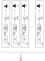
- FIG. 1 illustrates a configuration of an audio system according to the first embodiment.
- the audio system is installed in a vehicle and includes a number n of sub-systems SSi.
- i is an integer from 1 to n.
- the i-th sub-system SSi includes an i-th audio source device ASi, an i-th sound leakage reduction filter Wi, and an i-th speaker SPKi.
- the sub-system SSi is a system for an i-th seat in the vehicle.
- the audio source device ASi outputs a sound to which a user Pi sitting in the i-th seat listens.
- a sound Xi(f) output by the audio source device ASi is adjusted by the sound leakage reduction filter Wi with a frequency transfer function W ii (f) set in the sound leakage reduction filter Wi and is output from the speaker SPKi toward the user Pi.
- the speaker SPKi is disposed near the i-th seat.
- n 4
- i is an integer from 1 to 4
- the first seat of the vehicle is a right front seat of the vehicle
- the second seat of the vehicle is a left front seat of the vehicle
- the third seat of the vehicle is a right rear seat of the vehicle
- the fourth seat of the vehicle is a left rear seat of the vehicle is described below as an example.
- the speaker SPK1 of the sys-system SS1 is disposed at a right front door of the vehicle
- the speaker SPK2 of the sub-system SS2 is disposed at a left front door of the vehicle
- the speaker SPK3 of the sub-system SS3 is disposed at a right rear door of the vehicle
- the speaker SPK4 of the sub-system SS4 is disposed at a left rear door of the vehicle.
- the frequency transfer function W ii (f) of the sound leakage reduction filter Wi of the i-th sub-system SSi is calculated and set in advance as follows.
- a number Q (Q > 2) of microphones from a microphone MC1 to a microphone MCQ are used.
- Q 5 and five microphones from the microphone MC1 to a microphone MC5 are used is described below.
- the microphone MC1 is disposed at a sound listening position where a user sitting in the right front seat which is the first seat listens to a sound
- the microphone MC2, the microphone MC3, the microphone MC4, and the microphone MC5 are disposed at predetermined sound leakage reference positions outside the vehicle.
- the sound leakage reference positions are four positions near the speaker SPK1, the speaker SPK2, the speaker SPK3, and the speaker SPK4 and outside the vehicle.
- the microphones MC2, MC3, MC4, and MC5 are arranged in the same manner as the arrangement illustrated in FIG. 3A , and the microphone MC1 is disposed at a sound listening position where a user sitting in the left front seat which is the second seat listens to a sound.
- the microphones MC2, MC3, MC4, and MC5 are arranged in the same manner as the arrangement illustrated in FIG. 3A , and the microphone MC1 is disposed at a sound listening position where a user sitting in the right rear seat which is the third seat listens to a sound.
- the microphones MC2, MC3, MC4, and MC5 are arranged in the same manner as the arrangement illustrated in FIG. 3A , and the microphone MC1 is disposed at a sound listening position where a user sitting in the left rear seat which is the fourth seat listens to a sound.
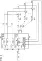
- the frequency transfer function W ii (f) of the sound leakage reduction filter Wi of the i-th sub-system SSi is calculated by a configuration illustrated in FIG. 4 .
- this configuration includes an audio source device ASi, a target setting section 301, an adaptive filter 302, a speaker SPKi, the five microphones MC1 to MC5 described above, and five subtractors AD1 to ADS.
- the target setting section 301 includes five filters 3011 that receive the output Xi(f) of the audio source device ASi.
- a target frequency transfer function H ij (f) from the speaker SPKi to the j-th microphone MCj (j is an integer from 1 to 5) is set.
- the adaptive filter 302 includes a variable filter 3021 that receives the output Xi(f) of the audio source device AS1, and an adaptive algorithm executing section 3022.
- the output of the variable filter 3021 is output from the speaker SPKi.
- the j-th subtractor ADj subtracts output Y j (f) of the j-th microphone MCj from output T j (f) of the j-th filter 3011 having the frequency transfer function H ij (f) set therein and outputs the result of the subtraction as a j-th error E j (f) to the adaptive filter 302.
- the adaptive algorithm executing section 3022 of the adaptive filter 302 executes a predetermined adaptive algorithm such as a multiple error filtered-X least mean square (MEFXLSM) algorithm and performs an adaptive operation of updating a frequency transfer characteristic Gii of the variable filter 3021 so as to minimize five errors E 1 (f) to E 5 (f) output from the five subtractors AD1 to AD5 as a whole.
- a predetermined adaptive algorithm such as a multiple error filtered-X least mean square (MEFXLSM) algorithm
- the adaptive algorithm executing section 3022 performs the adaptive operation.
- the frequency transfer characteristic Gii of the variable filter 3021 converges, the frequency transfer characteristic Gii that has converged is set as the frequency transfer function W ii (f) in the sound leakage reduction filter Wi of the sub-system SSi.
- a target frequency transfer function from the speaker SPKi to a user Pi is set as a frequency transfer function Hn(f), and frequency transfer functions H i2 to His of the second to fifth filters 3011 of the target setting section 301 are set to have a gain of 0 at all frequencies.
- Equation (1) an actual frequency transfer function from the speaker SPKi to the j-th microphone MCj is represented by C ij , and the frequency transfer function W ii (f) is calculated according to Equation (1), where A* is a complex conjugate of A.
- the sound leakage reduction filter Wi adjusts a sound to relatively reduce the volume of the sound at a frequency where gains of frequency transfer functions indicated by C im (f) (m is an integer from 2 to 5) from the speaker SPKi to the sound leakage reference positions (microphones MC2 to MC5) tend to be high relative to a gain of a frequency transfer function indicated by C i1 (f) from the speaker SPKi to the user Pi (microphone MC1), and to relatively increase the volume of the sound at a frequency where the gains of the frequency transfer functions indicated by C im (f) from the speakers SPKi to the sound leakage reference positions (microphones MC2 to MC5) tend to be low relative to the gain of the frequency transfer function indicated by C i1 (f) from the speaker SPKi to the user Pi (microphone MC1).
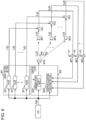
- multipliers MP1 to MP5 may be provided, and a multiplier MPj among the multipliers MP1 to MP5 may multiply an error E j (f) output by the subtractor ADj by a weight Kj and output the result of the multiplication to the adaptive filter 302.
- m is an integer from 2 to 5 as described above, m that maximizes C im * (f) ⁇ C im (f) / C i1 * (f) ⁇ C i1 (f) may be d, a weight Km for an error E m (f) other than an error E d (f) may be 0, and weights Kd and K1 for the errors E d (f) and E 1 (f) may be 1.
- the frequency transfer function W ii (f) set in the sound leakage reduction filter Wi is expressed according to Equation (2).
- W ii f 1 1 + C id ⁇ f C id f / C i1 ⁇ f C i1 f
- C im (f) that maximizes C im * (f) ⁇ C im (f) / C i1 * (f) ⁇ C i1 (f) is a frequency transfer function C i(i+1) from the speaker SPKi to the i+1-th microphone MC(i+1) closest to the speaker SPKi
- d may be equal to i + 1
- a microphone disposed at a sound leakage reference position where sound leakage is to be most suppressed among the sound leakage reference positions may be set as a microphone MCR, d may be equal to R, the weight Km for the error E m (f) other than the error E d (f) may be 0, and the weights Kd and K1 for the errors E d (f) and E 1 (f) may be 1.
- FIG. 6 illustrates a configuration of an audio system according to the second embodiment.
- all speakers SPKi are used for a user P1 sitting in the left front seat that is the first seat, unlike the first embodiment.
- the audio system includes a single audio source device AS1, four sound leakage reduction filters Wi, and the four speakers SPKi.
- i is an integer from 1 to 4.
- a sound Xi(f) output for the speaker SPKi by the audio source device AS1 is adjusted by the sound leakage reduction filter Wi with a frequency transfer function W ii (f) set in the sound leakage reduction filter Wi and is output from the speaker SPKi.
- the frequency transfer function W ii (f) of the sound leakage reduction filter Wi is calculated and set in advance.
- the frequency transfer function W ii (f) of the sound leakage reduction filter Wi is calculated in a configuration obtained by arranging microphones MC1 to MC5 as illustrated in FIG. 3A and replacing the audio source device ASi with the audio source device AS1 in the configuration illustrated in FIG. 4 or FIG. 5 .
- the speakers other than the i-th speaker SPKi are stopped outputting a sound.
- d may be equal to i + 1
- a weight Km for an error E m (f) other than an error E d (f) may be 0, and weights Kd and K1 for errors E d (f) and E 1 (f) may be 1 without any requirement as described above.
- the frequency transfer functions W ii (f) of the four sound leakage reduction filters Wi are independently calculated and thus the four sound leakage reduction filters Wi have different characteristics. Therefore, it can be expected that sounds adjusted using the different characteristics of the four sound leakage reduction filters Wi and output by the four speakers SPKi complement each other so as to suppress a reduction in the quality of a sound output by the audio source device AS1 and heard by the user P1.
- each of the sound leakage reduction filters Wi described in each of the embodiments is to adjust a gain at each frequency of a sound Xi(f) output by each of the audio source devices
- a graphic equalizer that adjusts a gain in each frequency band such as each 1/3 octave band may be used as each of the sound leakage reduction filters Wi.
Landscapes
- Physics & Mathematics (AREA)
- Engineering & Computer Science (AREA)
- Acoustics & Sound (AREA)
- Signal Processing (AREA)
- Multimedia (AREA)
- Health & Medical Sciences (AREA)
- General Health & Medical Sciences (AREA)
- Otolaryngology (AREA)
- Circuit For Audible Band Transducer (AREA)
- Fittings On The Vehicle Exterior For Carrying Loads, And Devices For Holding Or Mounting Articles (AREA)
Abstract
Description
- The present invention relates to a technique for suppressing leakage of a sound from an audio system installed in a vehicle to the outside of the vehicle.
- As a technique for suppressing leakage of a sound from an audio system installed in a vehicle to the outside of the vehicle, a technique is known in which an outside-oriented speaker for outputting a sound toward the outside of the vehicle is mounted and outputs a sound obtained by inverting the phase of a sound output by an audio system, as a cancellation sound that cancels the sound output by the audio system outside the vehicle (for example,
JP 2013-254101 A - According to the technique for outputting a cancellation sound from the outside-oriented speaker described above, the outside-oriented speaker is additionally required in addition to a speaker included in the audio system.
- In addition, according to this technique, since it is possible to suppress leakage of a sound output by the audio system only in the vicinity of the outside-oriented speaker, many outside-oriented speakers are required to suppress leakage of a sound from the audio system to the outside of the vehicle in a wide range of directions.
- Therefore, in a case where leakage of a sound from the audio system to the outside of the vehicle is to be sufficiently suppressed by the technique described above, an increase in the size of the configuration and the complexity of the configuration are unavoidable.
- Accordingly, it is an object of the present invention to suppress leakage of a sound from an audio system installed in a vehicle to the outside of the vehicle with a relatively simple configuration.
- The invention relates to an audio system and in-vehicle system according to the appended claims. Embodiments are disclosed in the dependent claims.
- According to aspects of the present invention, an audio system installed in a vehicle includes a sound source device, a speaker, and a filter configured to transmit a sound output by the sound source device to the speaker with a set frequency transfer characteristic. The frequency transfer characteristic set in the filter is a frequency transfer function that relatively reduces the volume of the sound at a frequency where a ratio of a gain of a frequency transfer function from the speaker to a reference position that is a predetermined relative position to the vehicle and is outside and near the vehicle with respect to a gain of a frequency transfer function from the speaker to a sound listening position where a target user sitting in a predetermined seat in the vehicle listens to the sound is relatively high, and that relatively increases the volume of the sound at a frequency where the ratio of the gain of the frequency transfer function from the speaker to the reference position with respect to the gain of the frequency transfer function from the speaker to the sound listening position where the target user listens to the sound is relatively low.
- In the audio system, the reference position may be a position near the speaker.
- In addition, according to aspects of the present invention, an audio system installed in a vehicle includes a sound source device, a speaker, and a filter configured to transmit a sound output by the sound source device to the speaker with a set frequency transfer characteristic. The frequency transfer characteristic set in the filter is a frequency transfer function that relatively reduces the volume of the sound at a frequency where a ratio of a gain of a frequency transfer function from the speaker to a plurality of different reference positions that are predetermined relative positions to the vehicle and are outside and near the vehicle with respect to a gain of a frequency transfer function from the speaker to a sound listening position where a target user sitting in a predetermined seat in the vehicle listens to the sound tends to be relatively high, and that relatively increases the volume of the sound at a frequency where the ratio of the gain of the frequency transfer function from the speaker to the plurality of reference positions with respect to the gain of the frequency transfer function from the speaker to the sound listening position where the target user listens to the sound tends to be relatively low.
- In an embodiment, when the number of the plurality of reference positions is L, the frequency transfer function from the speaker to the sound listening position where the target user listens to the sound is C11(f), a complex conjugate of C11(f) is C*11(f), a frequency transfer function from the speaker to the z-th reference position (z is an integer from 1 to L) is Ciz(f), and a complex conjugate of Ciz(f) is C*iz(f), the frequency transfer characteristic W11 set in the filter may be expressed by

- In an embodiment, the audio system may further include an adaptive filter whose input is the sound output by the sound source device and whose output is the input of the speaker, a frequency transfer characteristic of the adaptive filter may be obtained as a result of an adaptive operation performed by the adaptive filter using, as an error, a difference between a sound obtained by applying, to the sound output by the sound source device, the same frequency transfer function as the frequency transfer function from the speaker to the sound listening position where the target user listens to the sound and output of a microphone disposed at the sound listening position where the target user listens to the sound, and output of microphones disposed at the plurality of reference positions, and the obtained frequency transfer characteristic of the adaptive filter may be set as the frequency transfer characteristic in the filter.
- In an embodiment, the audio system may further include an adaptive filter whose input is the sound output by the sound source device and whose output is the input of the speaker, a frequency transfer characteristic of the adaptive filter may be obtained as a result of an adaptive operation performed by the adaptive filter using, as an error, a value obtained by weighing, with a predetermined weight, a difference between a sound obtained by applying, to the sound output by the sound source device, the same frequency transfer function as the frequency transfer function from the speaker to the sound listening position where the target user listens to the sound and output of a microphone disposed at the sound listening position where the target user listens to the sound, and a value obtained by weighing output of each of a plurality of microphones disposed at the plurality of reference positions with a weight set for each of the microphones, and the obtained frequency transfer characteristic of the adaptive filter may be set as the frequency transfer characteristic in the filter.
- In addition, according to aspects of the present invention, an audio system installed in a vehicle includes a sound source device, a plurality of first to n-th speakers (n is an integer greater than 2), and a plurality of first to n-th filters (n is an integer greater than 2). The i-th filter (i is an integer from 1 to n) transmits a sound output by the sound source device to the i-th speaker with a set frequency transfer characteristic. In addition, the frequency transfer characteristic set in the i-th filter is a frequency transfer function that relatively reduces the volume of the sound at a frequency where a ratio of a gain of a frequency transfer function from the i-th speaker to an i-th reference position that is a predetermined relative position to the vehicle and is outside the vehicle and near the i-th speaker with respect to a gain of a frequency transfer function from the i-th speaker to a sound listening position where a target user sitting in a predetermined seat in the vehicle listens to the sound is relatively high, and that relatively increases the volume of the sound at a frequency where the ratio of the gain of the frequency transfer function from the i-th speaker to the i-th reference position with respect to the gain of the frequency transfer function from the i-th speaker to the sound listening position where the target user listens to the sound is relatively low.
- In the audio system, the filters may be graphic equalizers.
- In addition, a plurality of audio systems as described herein may be provided, and a different seat among a plurality of seats in the vehicle may be set as the predetermined seat in each of the audio systems.
- According to each of the audio systems, with a relatively simple configuration including the filter for adjusting, with the set frequency transfer characteristic, the sound output by the sound source device and to be transferred to the speaker, it is possible to suppress leakage of a sound output by the speaker to the outside of the vehicle in a form in which the volume of the sound that has been output from the speaker and to which the user can listen and the quality of the output sound perceived by the user are not reduced as much as possible.
- As described above, according to the present invention, with a relatively simple configuration, it is possible to suppress leakage of a sound from an audio system installed in a vehicle to the outside of the vehicle.
-
FIG. 1 is a block diagram illustrating a configuration of an audio system according to a first embodiment of the present invention; -
FIG. 2 is a diagram illustrating an example of arrangement of speakers of the audio system according to the first embodiment of the present invention; -
FIGS. 3A to 3D are diagrams illustrating examples of arrangement of microphones in a case where transfer functions of sound leakage reduction filters according to the first embodiment of the present invention are learned; -
Fig. 4 is a diagram illustrating a configuration for learning the transfer functions of the sound leakage reduction filters according to the first embodiment of the present invention; -
FIG. 5 is a diagram illustrating another example of the configuration for learning the transfer functions of the sound leakage reduction filters according to the first embodiment of the present invention; and -
FIG. 6 is a block diagram illustrating a configuration of an audio system according to a second embodiment of the present invention. - Hereinafter, embodiments of the present invention are described.
- First, a first embodiment is described.
-
FIG. 1 illustrates a configuration of an audio system according to the first embodiment. - The audio system is installed in a vehicle and includes a number n of sub-systems SSi. In this case, i is an integer from 1 to n.
- The i-th sub-system SSi includes an i-th audio source device ASi, an i-th sound leakage reduction filter Wi, and an i-th speaker SPKi.
- The sub-system SSi is a system for an i-th seat in the vehicle. The audio source device ASi outputs a sound to which a user Pi sitting in the i-th seat listens. In the sub-system SSi, a sound Xi(f) output by the audio source device ASi is adjusted by the sound leakage reduction filter Wi with a frequency transfer function Wii(f) set in the sound leakage reduction filter Wi and is output from the speaker SPKi toward the user Pi. The speaker SPKi is disposed near the i-th seat.
- A case where n = 4, i is an integer from 1 to 4, the first seat of the vehicle is a right front seat of the vehicle, the second seat of the vehicle is a left front seat of the vehicle, the third seat of the vehicle is a right rear seat of the vehicle, and the fourth seat of the vehicle is a left rear seat of the vehicle is described below as an example.
- In this case, as illustrated in
FIG. 2 , for example, the speaker SPK1 of the sys-system SS1 is disposed at a right front door of the vehicle, the speaker SPK2 of the sub-system SS2 is disposed at a left front door of the vehicle, the speaker SPK3 of the sub-system SS3 is disposed at a right rear door of the vehicle, and the speaker SPK4 of the sub-system SS4 is disposed at a left rear door of the vehicle. - In this case, the frequency transfer function Wii(f) of the sound leakage reduction filter Wi of the i-th sub-system SSi is calculated and set in advance as follows.
- For the calculation of the frequency transfer function Wii(f), a number Q (Q > 2) of microphones from a microphone MC1 to a microphone MCQ are used. A case in which Q = 5 and five microphones from the microphone MC1 to a microphone MC5 are used is described below.
- As illustrated in
FIG. 3A , to calculate the frequency transfer function W11(f) of the sound leakage reduction filter W1 of the sub-system SS1, the microphone MC1 is disposed at a sound listening position where a user sitting in the right front seat which is the first seat listens to a sound, and the microphone MC2, the microphone MC3, the microphone MC4, and the microphone MC5 are disposed at predetermined sound leakage reference positions outside the vehicle. In this case, it is assumed that the sound leakage reference positions are four positions near the speaker SPK1, the speaker SPK2, the speaker SPK3, and the speaker SPK4 and outside the vehicle. - In addition, as illustrated in
FIG. 3B , to calculate a frequency transfer function W22(f) of the sound leakage reduction filter W2 of the sub-system SS2, the microphones MC2, MC3, MC4, and MC5 are arranged in the same manner as the arrangement illustrated inFIG. 3A , and the microphone MC1 is disposed at a sound listening position where a user sitting in the left front seat which is the second seat listens to a sound. - In addition, as illustrated in
FIG. 3C , to calculate a frequency transfer function W33(f) of the sound leakage reduction filter W3 of the sub-system SS3, the microphones MC2, MC3, MC4, and MC5 are arranged in the same manner as the arrangement illustrated inFIG. 3A , and the microphone MC1 is disposed at a sound listening position where a user sitting in the right rear seat which is the third seat listens to a sound. - In addition, as illustrated in
FIG. 3D , to calculate a frequency transfer function W44(f) of the sound leakage reduction filter W4 of the sub-system SS4, the microphones MC2, MC3, MC4, and MC5 are arranged in the same manner as the arrangement illustrated inFIG. 3A , and the microphone MC1 is disposed at a sound listening position where a user sitting in the left rear seat which is the fourth seat listens to a sound. - Then, the frequency transfer function Wii(f) of the sound leakage reduction filter Wi of the i-th sub-system SSi is calculated by a configuration illustrated in
FIG. 4 . - As illustrated in
FIG. 4 , this configuration includes an audio source device ASi, atarget setting section 301, anadaptive filter 302, a speaker SPKi, the five microphones MC1 to MC5 described above, and five subtractors AD1 to ADS. - The
target setting section 301 includes fivefilters 3011 that receive the output Xi(f) of the audio source device ASi. In the i-th filter 3011, a target frequency transfer function Hij(f) from the speaker SPKi to the j-th microphone MCj (j is an integer from 1 to 5) is set. - The
adaptive filter 302 includes avariable filter 3021 that receives the output Xi(f) of the audio source device AS1, and an adaptivealgorithm executing section 3022. The output of thevariable filter 3021 is output from the speaker SPKi. - The j-th subtractor ADj subtracts output Yj(f) of the j-th microphone MCj from output Tj(f) of the j-
th filter 3011 having the frequency transfer function Hij(f) set therein and outputs the result of the subtraction as a j-th error Ej(f) to theadaptive filter 302. - The adaptive
algorithm executing section 3022 of theadaptive filter 302 executes a predetermined adaptive algorithm such as a multiple error filtered-X least mean square (MEFXLSM) algorithm and performs an adaptive operation of updating a frequency transfer characteristic Gii of thevariable filter 3021 so as to minimize five errors E1(f) to E5(f) output from the five subtractors AD1 to AD5 as a whole. - In this configuration, while the audio source device ASi outputs a sound Xi(f), the adaptive
algorithm executing section 3022 performs the adaptive operation. When the frequency transfer characteristic Gii of thevariable filter 3021 converges, the frequency transfer characteristic Gii that has converged is set as the frequency transfer function Wii(f) in the sound leakage reduction filter Wi of the sub-system SSi. - In the
first filter 3011 of thetarget setting section 301, a target frequency transfer function from the speaker SPKi to a user Pi is set as a frequency transfer function Hn(f), and frequency transfer functions Hi2 to His of the second tofifth filters 3011 of thetarget setting section 301 are set to have a gain of 0 at all frequencies. - In this case, an actual frequency transfer function from the speaker SPKi to the j-th microphone MCj is represented by Cij, and the frequency transfer function Wii(f) is calculated according to Equation (1), where A* is a complex conjugate of A.

- According to the frequency transfer function Wii(f) calculated in the above-described manner and set in the sound leakage reduction filter Wi of the sub-system SSi, the sound leakage reduction filter Wi adjusts a sound to relatively reduce the volume of the sound at a frequency where gains of frequency transfer functions indicated by Cim(f) (m is an integer from 2 to 5) from the speaker SPKi to the sound leakage reference positions (microphones MC2 to MC5) tend to be high relative to a gain of a frequency transfer function indicated by Ci1(f) from the speaker SPKi to the user Pi (microphone MC1), and to relatively increase the volume of the sound at a frequency where the gains of the frequency transfer functions indicated by Cim(f) from the speakers SPKi to the sound leakage reference positions (microphones MC2 to MC5) tend to be low relative to the gain of the frequency transfer function indicated by Ci1(f) from the speaker SPKi to the user Pi (microphone MC1).
- As a result, it is possible to efficiently suppress sound leakage in a form in which the volume of a sound that has been output by the speaker SPKi and to which the i-th user Pi can listen and the quality of the output sound perceived by the user Pi are not reduced as much as possible.
- As illustrated in FIG. 5, to calculate the frequency transfer function Wii(f) of the sound leakage reduction filter Wi of the i-th sub-system SSI, multipliers MP1 to MP5 may be provided, and a multiplier MPj among the multipliers MP1 to MP5 may multiply an error Ej(f) output by the subtractor ADj by a weight Kj and output the result of the multiplication to the
adaptive filter 302. - In addition, in a case where m is an integer from 2 to 5 as described above, m that maximizes Cim *(f) · Cim(f) / Ci1 *(f) · Ci1(f) may be d, a weight Km for an error Em(f) other than an error Ed(f) may be 0, and weights Kd and K1 for the errors Ed(f) and E1(f) may be 1. In this case, the frequency transfer function Wii(f) set in the sound leakage reduction filter Wi is expressed according to Equation (2).

- In a case where the microphones MCj are arranged as illustrated in FIGS. 3A to 3D, since it is expected that Cim(f) that maximizes Cim *(f) · Cim(f) / Ci1 *(f) · Ci1(f) is a frequency transfer function Ci(i+1) from the speaker SPKi to the i+1-th microphone MC(i+1) closest to the speaker SPKi, d may be equal to i + 1, the weight Km for the error Em(f) other than the error Ed(f) may be 0, and the weights Kd and K1 for the errors Ed(f) and E1(f) may be 1 without any requirement.
- Alternatively, a microphone disposed at a sound leakage reference position where sound leakage is to be most suppressed among the sound leakage reference positions may be set as a microphone MCR, d may be equal to R, the weight Km for the error Em(f) other than the error Ed(f) may be 0, and the weights Kd and K1 for the errors Ed(f) and E1(f) may be 1.
- In this case, it is possible to most efficiently reduce the volume of a sound output by the speaker SPKi to a sound leakage reference position where the volume of a sound output by the speaker SPKi and leaking to the outside of the vehicle is the highest or to a sound leakage reference position where sound leakage is to be most suppressed. In addition, it is possible to reduce the amount of processing for performing the adaptive operation by the adaptive
algorithm executing section 3022. It is necessary to perform the adaptive operation in order to calculate the frequency transfer function Wii(f). - A second embodiment of the present invention is described below.
-
FIG. 6 illustrates a configuration of an audio system according to the second embodiment. - In the audio system according to the second embodiment, all speakers SPKi are used for a user P1 sitting in the left front seat that is the first seat, unlike the first embodiment.
- As illustrated in
FIG. 6 , the audio system includes a single audio source device AS1, four sound leakage reduction filters Wi, and the four speakers SPKi. In this case, i is an integer from 1 to 4. - A sound Xi(f) output for the speaker SPKi by the audio source device AS1 is adjusted by the sound leakage reduction filter Wi with a frequency transfer function Wii(f) set in the sound leakage reduction filter Wi and is output from the speaker SPKi.
- The frequency transfer function Wii(f) of the sound leakage reduction filter Wi is calculated and set in advance.
- The frequency transfer function Wii(f) of the sound leakage reduction filter Wi is calculated in a configuration obtained by arranging microphones MC1 to MC5 as illustrated in
FIG. 3A and replacing the audio source device ASi with the audio source device AS1 in the configuration illustrated inFIG. 4 orFIG. 5 . - To calculate the frequency transfer function Wii(f) of the i-th sound leakage reduction filter Wi, the speakers other than the i-th speaker SPKi are stopped outputting a sound.
- In addition, to calculate the frequency transfer function Wii(f) in the configuration in which the audio source device ASi is replaced with the audio source device AS1 in
FIG. 5 , d may be equal to i + 1, a weight Km for an error Em(f) other than an error Ed(f) may be 0, and weights Kd and K1 for errors Ed(f) and E1(f) may be 1 without any requirement as described above. - As described above, the frequency transfer functions Wii(f) of the four sound leakage reduction filters Wi are independently calculated and thus the four sound leakage reduction filters Wi have different characteristics. Therefore, it can be expected that sounds adjusted using the different characteristics of the four sound leakage reduction filters Wi and output by the four speakers SPKi complement each other so as to suppress a reduction in the quality of a sound output by the audio source device AS1 and heard by the user P1.
- Since the effect of each of the sound leakage reduction filters Wi described in each of the embodiments is to adjust a gain at each frequency of a sound Xi(f) output by each of the audio source devices, a graphic equalizer that adjusts a gain in each frequency band such as each 1/3 octave band may be used as each of the sound leakage reduction filters Wi.
Claims (6)
- An audio system installed in a vehicle, the audio system comprising:a sound source device;a speaker; anda filter configured to transmit a sound output by the sound source device to the speaker with a set frequency transfer characteristic, whereinthe frequency transfer characteristic set in the filter is a frequency transfer function that relatively reduces the volume of the sound at a frequency where a ratio of a gain of a frequency transfer function from the speaker to a plurality of different reference positions that are predetermined relative positions to the vehicle and are outside and near the vehicle with respect to a gain of a frequency transfer function from the speaker to a sound listening position where a target user sitting in a predetermined seat in the vehicle listens to the sound tends to be relatively high, and that relatively increases the volume of the sound at a frequency where the ratio of the gain of the frequency transfer function from the speaker to the plurality of reference positions with respect to the gain of the frequency transfer function from the speaker to the sound listening position where the target user listens to the sound tends to be relatively low.
- The audio system according to Claim 1, wherein when the number of the reference positions is L, the frequency transfer function from the speaker to the sound listening position where the target user listens to the sound is C11(f), a complex conjugate of C11(f) is C*11(f), a frequency transfer function from the speaker to the z-th reference position is Ciz(f), z is an integer from 1 to L, and a complex conjugate of Ciz(f) is C*iz(f), the frequency transfer characteristic W11 set in the filter is expressed by

- The audio system according to Claim 1 or 2, further comprising an adaptive filter whose input is the sound output by the sound source device and whose output is the input of the speaker, wherein
a frequency transfer characteristic of the adaptive filter is obtained as a result of an adaptive operation performed by the adaptive filter using, as an error, a difference between a sound obtained by applying, to the sound output by the sound source device, the same frequency transfer function as the frequency transfer function from the speaker to the sound listening position where the target user listens to the sound and output of a microphone disposed at the sound listening position where the target user listens to the sound, and output of microphones disposed at the plurality of reference positions, and the obtained frequency transfer characteristic of the adaptive filter is set as the frequency transfer characteristic in the filter. - The audio system according to one of Claims 1 to 3, further comprising an adaptive filter whose input is the sound output by the sound source device and whose output is the input of the speaker, wherein
a frequency transfer characteristic of the adaptive filter is obtained as a result of an adaptive operation performed by the adaptive filter using, as an error, a value obtained by weighing, with a predetermined weight, a difference between a sound obtained by applying, to the sound output by the sound source device, the same frequency transfer function as the frequency transfer function from the speaker to the sound listening position where the target user listens to the sound and output of a microphone disposed at the sound listening position where the target user listens to the sound, and a value obtained by weighing output of each of a plurality of microphones disposed at the plurality of reference positions with a weight set for each of the microphones, and the obtained frequency transfer characteristic of the adaptive filter is set as the frequency transfer characteristic in the filter. - The audio system according to any one of Claims 1 to 4, wherein
the filter is a graphic equalizer. - An in-vehicle system comprising a plurality of audio systems according to any one of Claims 1 to 5, wherein
in each of the audio systems, a different seat among a plurality of seats in the vehicle is set as the predetermined seat.
Applications Claiming Priority (1)
| Application Number | Priority Date | Filing Date | Title |
|---|---|---|---|
| JP2022081557A JP2023170086A (en) | 2022-05-18 | 2022-05-18 | Audio system and in-vehicle system |
Publications (2)
| Publication Number | Publication Date |
|---|---|
| EP4280209A2 true EP4280209A2 (en) | 2023-11-22 |
| EP4280209A3 EP4280209A3 (en) | 2024-02-14 |
Family
ID=86328584
Family Applications (1)
| Application Number | Title | Priority Date | Filing Date |
|---|---|---|---|
| EP23170946.0A Pending EP4280209A3 (en) | 2022-05-18 | 2023-05-02 | Audio system and in-vehicle system |
Country Status (4)
| Country | Link |
|---|---|
| US (1) | US12520098B2 (en) |
| EP (1) | EP4280209A3 (en) |
| JP (1) | JP2023170086A (en) |
| CN (1) | CN117098037A (en) |
Citations (3)
| Publication number | Priority date | Publication date | Assignee | Title |
|---|---|---|---|---|
| WO2010047907A1 (en) * | 2008-10-20 | 2010-04-29 | Bose Corporation | Adjusting leakage factors of an active noise reduction filter |
| JP2013254101A (en) | 2012-06-07 | 2013-12-19 | Mitsubishi Electric Corp | Sound leak prevention device |
| US10448180B1 (en) * | 2018-11-01 | 2019-10-15 | Toyota Motor Engineering & Manufacturing North America, Inc. | Systems and methods for vehicle external audio volume indication and control of the same |
Family Cites Families (5)
| Publication number | Priority date | Publication date | Assignee | Title |
|---|---|---|---|---|
| US20060002571A1 (en) * | 2004-06-30 | 2006-01-05 | International Business Machines Corporation | Self-adjusted car stereo system |
| US9560448B2 (en) * | 2007-05-04 | 2017-01-31 | Bose Corporation | System and method for directionally radiating sound |
| JP2009100187A (en) * | 2007-10-16 | 2009-05-07 | Fujitsu Ten Ltd | Sound controller |
| JP2010173605A (en) * | 2009-02-02 | 2010-08-12 | Fujitsu Ten Ltd | Acoustic system |
| US9191768B2 (en) * | 2011-02-24 | 2015-11-17 | Panasonic Intellectual Property Management Co., Ltd. | Diffracted sound reduction device, diffracted sound reduction method, and filter coefficient determination method |
-
2022
- 2022-05-18 JP JP2022081557A patent/JP2023170086A/en active Pending
-
2023
- 2023-05-02 EP EP23170946.0A patent/EP4280209A3/en active Pending
- 2023-05-04 US US18/143,164 patent/US12520098B2/en active Active
- 2023-05-10 CN CN202310518787.XA patent/CN117098037A/en active Pending
Patent Citations (3)
| Publication number | Priority date | Publication date | Assignee | Title |
|---|---|---|---|---|
| WO2010047907A1 (en) * | 2008-10-20 | 2010-04-29 | Bose Corporation | Adjusting leakage factors of an active noise reduction filter |
| JP2013254101A (en) | 2012-06-07 | 2013-12-19 | Mitsubishi Electric Corp | Sound leak prevention device |
| US10448180B1 (en) * | 2018-11-01 | 2019-10-15 | Toyota Motor Engineering & Manufacturing North America, Inc. | Systems and methods for vehicle external audio volume indication and control of the same |
Also Published As
| Publication number | Publication date |
|---|---|
| US12520098B2 (en) | 2026-01-06 |
| US20230379651A1 (en) | 2023-11-23 |
| JP2023170086A (en) | 2023-12-01 |
| EP4280209A3 (en) | 2024-02-14 |
| CN117098037A (en) | 2023-11-21 |
Similar Documents
| Publication | Publication Date | Title |
|---|---|---|
| EP3182407B1 (en) | Active noise control by adaptive noise filtering | |
| CN105814627B (en) | Active noise control system | |
| EP3767618B1 (en) | Noise reduction device, vehicle and noise reduction method | |
| EP2859772B1 (en) | Wind noise detection for in-car communication systems with multiple acoustic zones | |
| Molés-Cases et al. | Personal sound zones by subband filtering and time domain optimization | |
| US20100195844A1 (en) | Adaptive noise control system | |
| JP6870078B2 (en) | Noise estimation for dynamic sound adjustment | |
| EP3185241B1 (en) | Externally coupled loudspeaker system | |
| US11043202B2 (en) | Active noise control system, setting method of active noise control system, and audio system | |
| JP2021517986A (en) | Feedforward active noise control | |
| US11017792B2 (en) | Modular echo cancellation unit | |
| US12520098B2 (en) | Audio system and in-vehicle system | |
| US11044556B2 (en) | Systems and methods for canceling echo in a microphone signal | |
| EP2257082A1 (en) | Background noise estimation in a loudspeaker-room-microphone system | |
| EP4184943A1 (en) | Audio system | |
| EP4236284B1 (en) | Communication support system | |
| US11514922B1 (en) | Systems and methods for preparing reference signals for an acoustic echo canceler | |
| JP2019198110A (en) | Sound volume control device | |
| JP6556257B2 (en) | Volume control device, volume control method, and program | |
| JP4805034B2 (en) | Speaker system | |
| US20220199105A1 (en) | Signal component estimation using coherence |
Legal Events
| Date | Code | Title | Description |
|---|---|---|---|
| PUAI | Public reference made under article 153(3) epc to a published international application that has entered the european phase |
Free format text: ORIGINAL CODE: 0009012 |
|
| STAA | Information on the status of an ep patent application or granted ep patent |
Free format text: STATUS: THE APPLICATION HAS BEEN PUBLISHED |
|
| AK | Designated contracting states |
Kind code of ref document: A2 Designated state(s): AL AT BE BG CH CY CZ DE DK EE ES FI FR GB GR HR HU IE IS IT LI LT LU LV MC ME MK MT NL NO PL PT RO RS SE SI SK SM TR |
|
| PUAL | Search report despatched |
Free format text: ORIGINAL CODE: 0009013 |
|
| AK | Designated contracting states |
Kind code of ref document: A3 Designated state(s): AL AT BE BG CH CY CZ DE DK EE ES FI FR GB GR HR HU IE IS IT LI LT LU LV MC ME MK MT NL NO PL PT RO RS SE SI SK SM TR |
|
| RIC1 | Information provided on ipc code assigned before grant |
Ipc: G10K 11/178 20060101AFI20240111BHEP |
|
| STAA | Information on the status of an ep patent application or granted ep patent |
Free format text: STATUS: REQUEST FOR EXAMINATION WAS MADE |
|
| 17P | Request for examination filed |
Effective date: 20240808 |
|
| RBV | Designated contracting states (corrected) |
Designated state(s): AL AT BE BG CH CY CZ DE DK EE ES FI FR GB GR HR HU IE IS IT LI LT LU LV MC ME MK MT NL NO PL PT RO RS SE SI SK SM TR |
|
| STAA | Information on the status of an ep patent application or granted ep patent |
Free format text: STATUS: EXAMINATION IS IN PROGRESS |
|
| 17Q | First examination report despatched |
Effective date: 20250911 |