EP4280023A1 - Terminal device and charging method - Google Patents
Terminal device and charging method Download PDFInfo
- Publication number
- EP4280023A1 EP4280023A1 EP22917633.4A EP22917633A EP4280023A1 EP 4280023 A1 EP4280023 A1 EP 4280023A1 EP 22917633 A EP22917633 A EP 22917633A EP 4280023 A1 EP4280023 A1 EP 4280023A1
- Authority
- EP
- European Patent Office
- Prior art keywords
- keyboard
- tablet
- charging
- charging port
- power
- Prior art date
- Legal status (The legal status is an assumption and is not a legal conclusion. Google has not performed a legal analysis and makes no representation as to the accuracy of the status listed.)
- Pending
Links
Images

Classifications
-
- G—PHYSICS
- G06—COMPUTING OR CALCULATING; COUNTING
- G06F—ELECTRIC DIGITAL DATA PROCESSING
- G06F1/00—Details not covered by groups G06F3/00 - G06F13/00 and G06F21/00
- G06F1/26—Power supply means, e.g. regulation thereof
- G06F1/266—Arrangements to supply power to external peripherals either directly from the computer or under computer control, e.g. supply of power through the communication port, computer controlled power-strips
-
- G—PHYSICS
- G06—COMPUTING OR CALCULATING; COUNTING
- G06F—ELECTRIC DIGITAL DATA PROCESSING
- G06F1/00—Details not covered by groups G06F3/00 - G06F13/00 and G06F21/00
- G06F1/16—Constructional details or arrangements
- G06F1/1613—Constructional details or arrangements for portable computers
- G06F1/1633—Constructional details or arrangements of portable computers not specific to the type of enclosures covered by groups G06F1/1615 - G06F1/1626
- G06F1/1662—Details related to the integrated keyboard
-
- G—PHYSICS
- G06—COMPUTING OR CALCULATING; COUNTING
- G06F—ELECTRIC DIGITAL DATA PROCESSING
- G06F1/00—Details not covered by groups G06F3/00 - G06F13/00 and G06F21/00
- G06F1/16—Constructional details or arrangements
- G06F1/1601—Constructional details related to the housing of computer displays, e.g. of CRT monitors, of flat displays
- G06F1/1607—Arrangements to support accessories mechanically attached to the display housing
-
- G—PHYSICS
- G06—COMPUTING OR CALCULATING; COUNTING
- G06F—ELECTRIC DIGITAL DATA PROCESSING
- G06F1/00—Details not covered by groups G06F3/00 - G06F13/00 and G06F21/00
- G06F1/16—Constructional details or arrangements
- G06F1/1613—Constructional details or arrangements for portable computers
- G06F1/1626—Constructional details or arrangements for portable computers with a single-body enclosure integrating a flat display, e.g. Personal Digital Assistants [PDAs]
-
- G—PHYSICS
- G06—COMPUTING OR CALCULATING; COUNTING
- G06F—ELECTRIC DIGITAL DATA PROCESSING
- G06F1/00—Details not covered by groups G06F3/00 - G06F13/00 and G06F21/00
- G06F1/16—Constructional details or arrangements
- G06F1/1613—Constructional details or arrangements for portable computers
- G06F1/1633—Constructional details or arrangements of portable computers not specific to the type of enclosures covered by groups G06F1/1615 - G06F1/1626
- G06F1/1662—Details related to the integrated keyboard
- G06F1/1669—Detachable keyboards
-
- G—PHYSICS
- G06—COMPUTING OR CALCULATING; COUNTING
- G06F—ELECTRIC DIGITAL DATA PROCESSING
- G06F1/00—Details not covered by groups G06F3/00 - G06F13/00 and G06F21/00
- G06F1/16—Constructional details or arrangements
- G06F1/1613—Constructional details or arrangements for portable computers
- G06F1/1633—Constructional details or arrangements of portable computers not specific to the type of enclosures covered by groups G06F1/1615 - G06F1/1626
- G06F1/1675—Miscellaneous details related to the relative movement between the different enclosures or enclosure parts
- G06F1/1683—Miscellaneous details related to the relative movement between the different enclosures or enclosure parts for the transmission of signal or power between the different housings, e.g. details of wired or wireless communication, passage of cabling
-
- G—PHYSICS
- G06—COMPUTING OR CALCULATING; COUNTING
- G06F—ELECTRIC DIGITAL DATA PROCESSING
- G06F1/00—Details not covered by groups G06F3/00 - G06F13/00 and G06F21/00
- G06F1/26—Power supply means, e.g. regulation thereof
- G06F1/263—Arrangements for using multiple switchable power supplies, e.g. battery and AC
-
- G—PHYSICS
- G06—COMPUTING OR CALCULATING; COUNTING
- G06F—ELECTRIC DIGITAL DATA PROCESSING
- G06F3/00—Input arrangements for transferring data to be processed into a form capable of being handled by the computer; Output arrangements for transferring data from processing unit to output unit, e.g. interface arrangements
- G06F3/01—Input arrangements or combined input and output arrangements for interaction between user and computer
- G06F3/03—Arrangements for converting the position or the displacement of a member into a coded form
- G06F3/033—Pointing devices displaced or positioned by the user, e.g. mice, trackballs, pens or joysticks; Accessories therefor
- G06F3/0354—Pointing devices displaced or positioned by the user, e.g. mice, trackballs, pens or joysticks; Accessories therefor with detection of two-dimensional [2D] relative movements between the device, or an operating part thereof, and a plane or surface, e.g. 2D mice, trackballs, pens or pucks
- G06F3/03545—Pens or stylus
-
- H—ELECTRICITY
- H02—GENERATION; CONVERSION OR DISTRIBUTION OF ELECTRIC POWER
- H02J—ELECTRIC POWER NETWORKS; CIRCUIT ARRANGEMENTS OR SYSTEMS FOR SUPPLYING OR DISTRIBUTING ELECTRIC POWER; SYSTEMS FOR STORING ELECTRIC ENERGY
- H02J50/00—Circuit arrangements or systems for wireless supply or distribution of electric power
-
- H—ELECTRICITY
- H02—GENERATION; CONVERSION OR DISTRIBUTION OF ELECTRIC POWER
- H02J—ELECTRIC POWER NETWORKS; CIRCUIT ARRANGEMENTS OR SYSTEMS FOR SUPPLYING OR DISTRIBUTING ELECTRIC POWER; SYSTEMS FOR STORING ELECTRIC ENERGY
- H02J50/00—Circuit arrangements or systems for wireless supply or distribution of electric power
- H02J50/10—Circuit arrangements or systems for wireless supply or distribution of electric power using inductive coupling
-
- H—ELECTRICITY
- H02—GENERATION; CONVERSION OR DISTRIBUTION OF ELECTRIC POWER
- H02J—ELECTRIC POWER NETWORKS; CIRCUIT ARRANGEMENTS OR SYSTEMS FOR SUPPLYING OR DISTRIBUTING ELECTRIC POWER; SYSTEMS FOR STORING ELECTRIC ENERGY
- H02J7/00—Circuit arrangements for charging or discharging batteries or for supplying loads from batteries
- H02J7/855—Circuit arrangements for charging or discharging batteries or for supplying loads from batteries with circuits adapted for supplying loads from the battery
-
- H—ELECTRICITY
- H02—GENERATION; CONVERSION OR DISTRIBUTION OF ELECTRIC POWER
- H02J—ELECTRIC POWER NETWORKS; CIRCUIT ARRANGEMENTS OR SYSTEMS FOR SUPPLYING OR DISTRIBUTING ELECTRIC POWER; SYSTEMS FOR STORING ELECTRIC ENERGY
- H02J7/00—Circuit arrangements for charging or discharging batteries or for supplying loads from batteries
- H02J7/865—Battery or charger load switching, e.g. concurrent charging and load supply
-
- H—ELECTRICITY
- H02—GENERATION; CONVERSION OR DISTRIBUTION OF ELECTRIC POWER
- H02J—ELECTRIC POWER NETWORKS; CIRCUIT ARRANGEMENTS OR SYSTEMS FOR SUPPLYING OR DISTRIBUTING ELECTRIC POWER; SYSTEMS FOR STORING ELECTRIC ENERGY
- H02J7/00—Circuit arrangements for charging or discharging batteries or for supplying loads from batteries
- H02J7/90—Regulation of charging or discharging current or voltage
- H02J7/933—Regulation of charging or discharging current or voltage the cycle being controlled or terminated in response to electric parameters
-
- G—PHYSICS
- G06—COMPUTING OR CALCULATING; COUNTING
- G06F—ELECTRIC DIGITAL DATA PROCESSING
- G06F2200/00—Indexing scheme relating to G06F1/04 - G06F1/32
- G06F2200/16—Indexing scheme relating to G06F1/16 - G06F1/18
- G06F2200/163—Indexing scheme relating to constructional details of the computer
- G06F2200/1632—Pen holder integrated in the computer
-
- G—PHYSICS
- G06—COMPUTING OR CALCULATING; COUNTING
- G06F—ELECTRIC DIGITAL DATA PROCESSING
- G06F2200/00—Indexing scheme relating to G06F1/04 - G06F1/32
- G06F2200/16—Indexing scheme relating to G06F1/16 - G06F1/18
- G06F2200/163—Indexing scheme relating to constructional details of the computer
- G06F2200/1633—Protecting arrangement for the entire housing of the computer
-
- Y—GENERAL TAGGING OF NEW TECHNOLOGICAL DEVELOPMENTS; GENERAL TAGGING OF CROSS-SECTIONAL TECHNOLOGIES SPANNING OVER SEVERAL SECTIONS OF THE IPC; TECHNICAL SUBJECTS COVERED BY FORMER USPC CROSS-REFERENCE ART COLLECTIONS [XRACs] AND DIGESTS
- Y02—TECHNOLOGIES OR APPLICATIONS FOR MITIGATION OR ADAPTATION AGAINST CLIMATE CHANGE
- Y02E—REDUCTION OF GREENHOUSE GAS [GHG] EMISSIONS, RELATED TO ENERGY GENERATION, TRANSMISSION OR DISTRIBUTION
- Y02E60/00—Enabling technologies; Technologies with a potential or indirect contribution to GHG emissions mitigation
- Y02E60/10—Energy storage using batteries
Definitions
- This application relates to the field of terminal technologies, and in particular, to a terminal device and a charging method.
- a tablet computer also referred to as a portable computer (Tablet Personal Computer, Tablet PC)
- Tablet PC Tablet Personal Computer
- a tablet computer serving as a host may be externally connected to a keyboard, that is, the tablet computer may be manipulated through the keyboard.
- the tablet computer and the keyboard may be connected to each other through a pogo pin, the pogo pin includes a form such as 3pin, 4pin or 5pin, and currently the form of 3pin is applied most widely.
- 3pin mainly includes a power supply pin for supplying power, a data pin, and a ground GND pin.
- the data pin may further implement detection between the tablet computer and the keyboard.
- each keyboard is equipped with a battery, and the battery of the keyboard is charged or power is supplied to the keyboard through a tablet. In this way, of the keyboard is high in costs and large in volume. Because of existence of the battery of the keyboard, the keyboard cannot be made very thin, and portability of the
- this application provides a terminal device and a charging method, to implement a keyboard without a battery, thereby helping implement lightening and thinning for the keyboard and helping implement quick charging.
- this application provides a terminal device, including: a tablet and a keyboard, where
- the keyboard is equipped with a storage portion of a stylus, and when the stylus is stored in the storage portion and the keyboard is not connected to the tablet, the keyboard wirelessly charges the stylus by using the second external power supply.
- the second controller determines that the keyboard is connected to the tablet, and receives a power supply instruction sent by the first controller, the second controller controls the power line in the 3pin of the keyboard to output a voltage.
- the tablet when the keyboard is connected to the tablet, and the second charging port of the keyboard is unplugged from the second external power supply, the tablet is configured to continuously supply power to the keyboard.
- the tablet includes: a low-dropout linear regulator and a diode; and a power output end of the low-dropout linear regulator is connected to an anode of the diode, and a cathode of the diode is connected to the power line in the 3pin of the tablet; and an input end of the low-dropout linear regulator is connected to a system power supply of the tablet.
- the low-dropout linear regulator includes an enabling pin; and the first controller is configured to: when receiving power failure information sent by the second controller, send an enabling signal to the enabling pin, and the power output end of the low-dropout linear regulator outputs a voltage.
- the tablet when the second charging port of the keyboard is connected to the second external power supply, the tablet is first disconnected from and then connected to the keyboard, and the second controller of the keyboard is configured to perform handshake communication with the first controller of the tablet; and the first controller is configured to recognize that the keyboard is connected to the tablet.
- the keyboard includes: a charging switch; and
- the tablet is further configured to supply power to an external device connected to the tablet.
- the keyboard further includes: a buckboost circuit and a wireless charging chip;
- the terminal device includes: a tablet and a keyboard, where the tablet includes: a first controller, a first charging port, and a battery; the keyboard includes: a second controller and a second charging port; and the keyboard includes no battery; the first controller communicates with the second controller through data lines in 3pin; and
- the terminal device includes: a tablet and a keyboard, where the tablet includes: a first controller, a first charging port, and a battery; the keyboard includes: a second controller and a second charging port; and the keyboard includes no battery; and the first controller communicates with the second controller through data lines in 3pin. Because the keyboard includes no battery, the volume and the weight of the keyboard are reduced, and lightening and thinning are implemented for the keyboard. In addition, a case that the keyboard includes no battery does not affect the keyboard in charging the stylus since the keyboard includes the second charging port such as a Type-C port that can be externally connected to a charger in a wired manner to charge the stylus while supplying power to the keyboard.
- the second charging port such as a Type-C port that can be externally connected to a charger in a wired manner to charge the stylus while supplying power to the keyboard.
- a side of the keyboard includes a wired charging port
- a side of the tablet also includes a wired charging port
- a side whose charging power is larger is selected to perform charging.
- Such a charging speed is high, and fast full charging can be implemented.
- the charging power of the side of the keyboard is larger, the side of the keyboard is selected, and the wired charging port of the side of the tablet receives no external power.
- the charging power of the side of the tablet is larger, the side of the tablet is selected to perform charging, and the wired charging port of the side of the keyboard receives no external power.
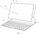
- FIG. 1 is a schematic diagram of a terminal device according to an embodiment of this application.
- the terminal device provided in this application includes: a tablet 200, a keyboard 300, and a stylus 100.
- the keyboard 300 includes a stylus storage portion 301, and the stylus 100 may be inserted into the stylus storage portion 301 and be wirelessly charged.
- the tablet 200 includes a touch screen.
- the stylus 100 may input information on the touch screen 201, and the touch screen 201 may sense the information inputted by the stylus 100 and respond.
- the stylus 100 and the keyboard 300 may each input information to the tablet.
- a touch region may be arranged on the keyboard 300, and the stylus 100 may operate the touch region on the keyboard 300.
- a wired connection is used between the keyboard 300 and the tablet 200, and includes a data communication connection and a power supply connection.
- the keyboard 300 and the tablet 200 are connected to each other directly through 3pin.
- the 3pin includes a data line, namely, a Data pin, a GND pin, and a power line, namely, a VBUS pin.
- the keyboard 300 and the tablet 200 communicate with each other through a one-line serial port of the Data pin.
- a stylus is located on the top of a conventional tablet, the tablet charges the stylus.
- the stylus is stored in the storage portion of the keyboard, is hidden, and is not prone to fall off.
- the keyboard storing the stylus needs to charge the stylus. If the keyboard is equipped with a battery, the costs are high, and the volume is large. In addition, the large weight is not conducive to lightening and thinning of the keyboard. Therefore, to reduce the costs and make the keyboard lighter and thinner, in the terminal device provided in this application, only the tablet includes a battery, but the keyboard includes no battery Specific implementations of terminal devices provided in this application are introduced below with reference to accompanying drawings.
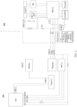
- FIG. 2 is a diagram of an internal architecture of another terminal device according to an embodiment of the present application.
- the terminal device provided in this application includes: a tablet 200 and a keyboard 300.
- the tablet 200 includes: a first controller MCU1 (using a microcontroller unit MCU as an example), a first charging port Type-C1 (using a typeC port as an example), and a battery VBAT.
- the keyboard 300 includes: a second controller MCU2 (using a microcontroller unit MCU as an example) and a second charging port Type-C2 (using a typeC port as an example).
- the keyboard 300 includes no battery.
- the keyboard provided in this embodiment of this application includes an independent controller, and the controller may complete charging control on the side of the keyboard, and implement communication control and charging control on the side of the tablet. Additionally, the controller may further respond to input information of a Keypad of the keyboard and respond to input information of a touch area TouchPad of the keyboard.
- the first controller MCU1 communicates with the second controller MCU2 through data lines Data in 3pin.
- the first charging port Type-C1 When the first charging port Type-C1 is connected to a first external power supply, and the second charging port Type-C2 is connected to a second external power supply, in a case that a charging power of the first charging port Type-C1 is greater than a charging power of the second charging port Type-C2, the first charging port Type-C1 is selected to charge the tablet 200 and power is supplied to the keyboard 300 through a power line in the 3pin; otherwise, the second charging port Type-C2 is selected to supply power to the keyboard 300 and the tablet 200 is charged through a power line in the 3pin.
- a side whose charging power is larger is selected to perform charging and supply power. In this way, charging efficiency can be improved, and full charging can be completed fast in a short time.
- the second controller MCU2 of the side of the keyboard performs charging communication with the second charging port Type-C2 through the BC1.2 protocol.
- the keyboard further includes: a buckboost circuit and a wireless charging chip IC;
- the output voltage of the buckboost circuit is not specifically limited, and may be, for example, 5.5 V in some cases.
- the output end of the wireless charging IC is used for charging the stylus. Because the stylus is wirelessly charged, a transmitting coil for wireless charging is located in the stylus storage portion, that is, a stylus container, and the wireless charging IC supplies power to the transmitting coil, and a receiving coil is located in the stylus.
- the keyboard includes no battery, the volume and the weight of the keyboard are reduced, and lightening and thinning are implemented for the keyboard.
- a case that the keyboard includes no battery does not affect the keyboard in charging the stylus since the keyboard includes the second charging port such as a Type-C port that can be externally connected to a charger in a wired manner to charge the stylus while supplying power to the keyboard.
- the keyboard may alternatively charge the tablet through an external charger.
- a side of the keyboard includes a wired charging port
- a side of the tablet also includes a wired charging port
- a side whose charging power is larger is selected to perform charging.
- Such a charging speed is high, and fast full charging can be implemented.
- the side of the keyboard is selected, and the wired charging port of the side of the tablet receives no external power.
- the charging power of the side of the tablet is larger, the side of the tablet is selected to perform charging, and the wired charging port of the side of the keyboard receives no external power.
- the second charging port Type-C2 of the keyboard is connected to an external charger, the first charging port Type-C1 of the tablet is not connected to any external charger, and the keyboard charges the battery of the tablet through the external charger. Meanwhile, if the first charging port Type-C1 of the tablet is plugged with an OTG external device such as a USB flash drive, the tablet may further supply power to the external device.
- the keyboard includes no battery, the second charging port Type-C2 of the keyboard is not connected to any external charger, and the tablet supplies power to the keyboard through the power line in the 3pin and also charges the stylus when the stylus is located in the storage portion.
- the keyboard is equipped with a storage portion of a stylus, and when the stylus is stored in the storage portion and the keyboard is not connected to the tablet, the keyboard wirelessly charges the stylus by using the second external power supply.
- the second charging port Type-C2 of the keyboard is connected to an external charger, the keyboard is equipped with a stylus storage portion, the keyboard is not connected to the tablet, and the keyboard wirelessly charges the stylus through the external charger. In this way, charging efficiency can be improved.
- the power supply port in the 3pin of the keyboard is also configured to be not electrified. In this way, electrochemical corrosion of the power supply port in the 3pin of the keyboard can be reduced.
- the power line in the 3pin of the keyboard is electrified.
- the second controller determines that the keyboard is connected to the tablet, and receives a power supply instruction sent by the first controller, the second controller controls the power line in the 3pin of the keyboard to output a voltage.
- the power lines in the 3pin of the keyboard and the tablet are electrified only when power needs to be supplied, and are not electrified if power does not need to be supplied. In this way, ports of the power lines can be protected from corrosion, and service life can be prolonged.
- the tablet may continuously supply power to the keyboard, that is, when the keyboard is connected to the tablet, and the second charging port of the keyboard is unplugged from the second external power supply, the tablet is used for continuously supplying power to the keyboard.
- the second external power supply is preferentially used to supply power to the keyboard.
- the tablet may perform seamless switching to supply power to the keyboard.
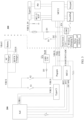
- FIG. 3 is a schematic diagram of still another terminal device according to an embodiment of this application.
- a tablet provided in this embodiment includes: a low-dropout linear regulator (LDO) and a diode D3.
- LDO low-dropout linear regulator
- an output voltage of the low-dropout linear regulator may be a voltage matching VBUS, for example, 3.3 V
- a power output end of the low-dropout linear regulator (LDO) is connected to an anode of the diode D3, and a cathode of the diode D3 is connected to the power line in the 3pin of the tablet 200; and an input end of the low-dropout linear regulator (LDO) is connected to a system power supply of the tablet 200.
- the low-dropout linear regulator (LDO) outputs a voltage to VBUS through the diode D3, that is, supplies power to the side of the keyboard through a diode D2 on the side of the keyboard 300, and may charge a stylus if the stylus is located in a stylus container on the side of the keyboard.
- the low-dropout linear regulator (LDO) dedicated to supplying power to VBUS is arranged, power may be supplied to VBUS at any time.
- the side of the tablet may supply power to the keyboard in time, to continuously supply power to the keyboard.
- the low-dropout linear regulator may include an enabling pin EN;
- the first controller MCU1 is configured to: when receiving power failure information sent by the second controller MCU2, send an enabling signal to the enabling pin EN of the low-dropout linear regulator (LDO), that is, enable the low-dropout linear regulator (LDO) to begin working, and the power output end of the low-dropout linear regulator (LDO) outputs a voltage.
- LDO low-dropout linear regulator
- the low-dropout linear regulator (LDO) may alternatively not include any enabling pin EN, and the low-dropout linear regulator (LDO) is always outputting a voltage.
- the low-dropout linear regulator (LDO) outputs a voltage only when power needs to be supplied. In this way, energy can be saved, and power consumption can be reduced.
- the tablet 200 in addition to the first controller MCU1, the tablet 200 further includes a system-on-a-chip SoC. Between the system-on-a-chip SoC and the first controller MCU1, communication, for example, serial communication such as I2C or SPI is performed. Additionally, between the two, an interrupt port INT may be further included, and a reset port RST is further included.
- a system-on-a-chip SoC Between the system-on-a-chip SoC and the first controller MCU1, communication, for example, serial communication such as I2C or SPI is performed. Additionally, between the two, an interrupt port INT may be further included, and a reset port RST is further included.
- Data communication between the system-on-a-chip SoC and the first controller MCU1 may be bidirectional communication, that is, includes both a transmission channel TX and a receiving channel RX.
- the system-on-a-chip SoC may serve as a host computer of the first controller MCU1, to control the first controller MCU1. Additionally, the system-on-a-chip SoC also controls the first charging port Type-C1.
- the serial communication manner between MCU1 and MCU2 may be UART. Because only one-line communication is performed between MCU1 and MCU2, the data line may further implement an interrupt INT function, and may further implement a signal sampling function, for example, perform analog-to-digital conversion ADC on a sampled signal.
- the second charging port Type-C2 of the keyboard 300 is connected to an external charger, the tablet 200 may be taken away from and placed on the keyboard 300 at any time, and a case that the keyboard 300 cannot be recognized when the tablet 200 is taken away from and then placed on the keyboard 300 will not occur.
- the tablet 200 When the second charging port Type-C2 of the keyboard 300 is connected to the second external power supply, the tablet 200 is first disconnected from and then connected to the keyboard 300, and the second controller MCU2 of the keyboard 300 is configured to perform handshake communication with the first controller MCU1 of the tablet 200; and the first controller MCU1 is configured to recognize that the keyboard 300 is connected to the tablet 200. For example, recognition is performed once again between the tablet 200 and the keyboard 300, for example, a heartbeat signal may be sent. If there is a response within a preset time period, it indicates connection, and the tablet resumes connection. If there is no response beyond the preset time period, it indicates disconnection, and the tablet 200 resumes disconnection.
- the keyboard 300 includes: a charging switch S5.
- a first end of the charging switch S5 is connected to a power supply pin of the second charging port Type-C2 of the keyboard.
- a second end of the charging switch S5 is connected to the power line in the 3pin of the keyboard 300.
- the second controller MCU2 of the keyboard 300 is further configured to: determine that the second charging port Type-C2 is connected to the second external power supply; and MCU2 controls, when the tablet 200 is connected to the keyboard 300 and the first charging port Type-C1 of the tablet 200 is not connected to the first external power supply, the charging switch S5 to close, and the keyboard 300 charges the battery VBAT of the tablet 200 by using the second external power supply.
- MCU2 controls S5 to open.
- MCU2 controls S5 to close, thereby supplying power to VBUS of the tablet.
- the tablet 200 further includes: a first switch S 1 and a second switch S2.
- a first end of the first switch S 1 is connected to the first charging port Type-C1, and a second end of the first switch S1 is connected to an SC Charger, that is, a switched-capacitor charger for charging the battery VBAT, and is also connected to a BUCK Charger.
- SC Charger that is, a switched-capacitor charger for charging the battery VBAT
- BUCK Charger the tablet provided in this embodiment of this application further includes the BUCK Charger. That is, the SC Charger may fast charge the battery, and the BUCK Charger may slowly charge the battery.
- MCU1 controls S1 to open.
- a first end of the second switch S2 is connected to the power line in the 3pin of the side of the tablet, that is, VBUS in Pogopin of the tablet in FIG. 3 , and a second end of the second switch S2 is connected to the SC Charger for charging the battery VBAT, and is also connected to the BUCK Charger.
- the second charging port Type-C2 of the keyboard 300 is connected to an external power supply, and the tablet is connected to the keyboard, the keyboard supplies power to and charges the tablet.
- the second switch S2 needs to be controlled to close, that is, VBUS of the side of the keyboard supplies power to VBUS of the side of the tablet, and Pogopin of the tablet charges the battery VBAT through the second switch S2.
- the side of the keyboard 300 further includes a first diode D1 and a second diode D2, an anode of the first diode D1 is connected to a voltage output end of the second charging port Type-C2, and a cathode of the first diode D1 is connected to an input end of a buckboost circuit.
- An anode of the second diode D2 is connected to VBUS in the 3pin, and a cathode of the second diode D2 is connected to the cathode of the first diode D1.
- the side of the keyboard 300 further includes a low-dropout linear regulator (LDO), and the LDO on the side of the keyboard 300 is configured to convert 5.5 V outputted by the buckboost circuit into stable 3.3 V to supply power to the second controller MCU2.
- LDO low-dropout linear regulator
- the embodiments of this application further provide a charging method for a terminal device. The method is described in detail below with reference to the accompanying drawings.
- FIG. 4 is a flowchart of a charging method for a terminal device according to an embodiment of this application.
- the terminal device includes: a tablet and a keyboard, where the tablet includes: a first controller, a first charging port, and a battery; the keyboard includes: a second controller and a second charging port; and the keyboard includes no battery; and the first controller communicates with the second controller through data lines in 3pin.
- the charging method includes:
- a side whose charging power is larger is selected to perform charging and supply power. In this way, charging efficiency can be improved, and full charging can be completed fast in a short time.
- a side of the keyboard includes a wired charging port
- a side of the tablet also includes a wired charging port
- a side whose charging power is larger is selected to perform charging.
- Such a charging speed is high, and fast full charging can be implemented.
- the side of the keyboard is selected, and the wired charging port of the side of the tablet receives no external power.
- the charging power of the side of the tablet is larger, the side of the tablet is selected to perform charging, and the wired charging port of the side of the keyboard receives no external power.
- At least one (item) refers to one or more and “a plurality of” refers to two or more.
- the term “and/or” describes an association between associated objects and represents that three associations may exist.
- a and/or B may indicate that only A exists, only B exists, and both A and B exist, where A and B may be singular or plural.
- the character “/” in this specification generally indicates an “or” relationship between the associated objects.
- At least one of the following or a similar expression thereof indicates any combination of the following, and includes any combination of one or more of the following.
- At least one of a, b, or c may represent a, b, c, "a and b", “a and c", “b and c", or "a, b, and c", where a, b, and c may be singular or plural.
Landscapes
- Engineering & Computer Science (AREA)
- Theoretical Computer Science (AREA)
- General Engineering & Computer Science (AREA)
- Physics & Mathematics (AREA)
- General Physics & Mathematics (AREA)
- Computer Hardware Design (AREA)
- Human Computer Interaction (AREA)
- Power Engineering (AREA)
- Computer Networks & Wireless Communication (AREA)
- Power Sources (AREA)
- Charge And Discharge Circuits For Batteries Or The Like (AREA)
Abstract
Description
- This application claims priority to
Chinese Patent Application No. 202210355213.0, filed with the China National Intellectual Property Administration on April 01, 2022 - This application relates to the field of terminal technologies, and in particular, to a terminal device and a charging method.
- A tablet computer, also referred to as a portable computer (Tablet Personal Computer, Tablet PC), is a computer that is small in size and easy to carry. For ease of use, currently, a tablet computer serving as a host may be externally connected to a keyboard, that is, the tablet computer may be manipulated through the keyboard.
- The tablet computer and the keyboard may be connected to each other through a pogo pin, the pogo pin includes a form such as 3pin, 4pin or 5pin, and currently the form of 3pin is applied most widely. 3pin mainly includes a power supply pin for supplying power, a data pin, and a ground GND pin. In addition to transmitting data of a touchpad, data of the keyboard, data of a charging protocol, and other data, the data pin may further implement detection between the tablet computer and the keyboard.
- Currently, each keyboard is equipped with a battery, and the battery of the keyboard is charged or power is supplied to the keyboard through a tablet. In this way, of the keyboard is high in costs and large in volume. Because of existence of the battery of the keyboard, the keyboard cannot be made very thin, and portability of the
- To resolve the foregoing problem, this application provides a terminal device and a charging method, to implement a keyboard without a battery, thereby helping implement lightening and thinning for the keyboard and helping implement quick charging.
- According to a first aspect, this application provides a terminal device, including: a tablet and a keyboard, where
- the tablet includes: a first controller, a first charging port, and a battery;
- the keyboard includes: a second controller and a second charging port; and the keyboard includes no battery;
- the first controller communicates with the second controller through data lines in 3pin; and
- when the first charging port is connected to a first external power supply, and the second charging port is connected to a second external power supply, in a case that a charging power of the first charging port is greater than a charging power of the second charging port, the first charging port is selected to charge the tablet and power is supplied to the keyboard through a power line in the 3pin; otherwise, the second charging port is selected to supply power to the keyboard and the tablet is charged through a power line in the 3pin.
- In a possible implementation, the keyboard is equipped with a storage portion of a stylus, and when the stylus is stored in the storage portion and the keyboard is not connected to the tablet, the keyboard wirelessly charges the stylus by using the second external power supply.
- In a possible implementation, when the second charging port of the keyboard is connected to the second external power supply and the keyboard is not connected to the tablet, neither the power line in the 3pin of the keyboard nor the power line in the 3pin of the tablet is electrified.
- In a possible implementation, after the second controller determines that the keyboard is connected to the tablet, and receives a power supply instruction sent by the first controller, the second controller controls the power line in the 3pin of the keyboard to output a voltage.
- In a possible implementation, when the keyboard is connected to the tablet, and the second charging port of the keyboard is unplugged from the second external power supply, the tablet is configured to continuously supply power to the keyboard.
- In a possible implementation, the tablet includes: a low-dropout linear regulator and a diode; and
a power output end of the low-dropout linear regulator is connected to an anode of the diode, and a cathode of the diode is connected to the power line in the 3pin of the tablet; and an input end of the low-dropout linear regulator is connected to a system power supply of the tablet. - In a possible implementation, the low-dropout linear regulator includes an enabling pin; and
the first controller is configured to: when receiving power failure information sent by the second controller, send an enabling signal to the enabling pin, and the power output end of the low-dropout linear regulator outputs a voltage. - In a possible implementation, when the second charging port of the keyboard is connected to the second external power supply, the tablet is first disconnected from and then connected to the keyboard, and the second controller of the keyboard is configured to perform handshake communication with the first controller of the tablet; and the first controller is configured to recognize that the keyboard is connected to the tablet.
- In a possible implementation, the keyboard includes: a charging switch; and
- a first end of the charging switch is connected to a power supply pin of the second charging port of the keyboard; a second end of the charging switch is connected to the power line in the 3pin of the keyboard; and
- the second controller of the keyboard is further configured to: determine that the second charging port is connected to the second external power supply; and control, when the tablet is connected to the keyboard and the first charging port of the tablet is not connected to the first external power supply, the charging switch to close, and the keyboard charges the battery of the tablet by using the second external power supply.
- In a possible implementation, the tablet is further configured to supply power to an external device connected to the tablet.
- In a possible implementation, the keyboard further includes: a buckboost circuit and a wireless charging chip;
- an input end of the buckboost circuit is configured to connect to a power supply pin of the second charging port;
- an output end of the buckboost circuit is connected to an input end of the wireless charging chip; and
- an output end of the wireless charging chip is configured to charge the stylus.
- This application further provides a charging method for a terminal device. The terminal device includes: a tablet and a keyboard, where the tablet includes: a first controller, a first charging port, and a battery; the keyboard includes: a second controller and a second charging port; and the keyboard includes no battery; the first controller communicates with the second controller through data lines in 3pin; and
- the charging method includes:
- when the first charging port is connected to a first external power supply, and the second charging port is connected to a second external power supply, comparing a charging power of the first charging port with a charging power of the second charging port;
- in a case that the charging power of the first charging port is greater than the charging power of the second charging port, selecting the first charging port to charge the tablet and supplying power to the keyboard through a power line in the 3pin; and
- in a case that the charging power of the first charging port is less than the charging power of the second charging port, selecting the second charging port to supply power to the keyboard and charging the tablet through a power line in the 3pin.
- This application has at least the following advantages:
- The terminal device provided in embodiments of this application includes: a tablet and a keyboard, where the tablet includes: a first controller, a first charging port, and a battery; the keyboard includes: a second controller and a second charging port; and the keyboard includes no battery; and the first controller communicates with the second controller through data lines in 3pin. Because the keyboard includes no battery, the volume and the weight of the keyboard are reduced, and lightening and thinning are implemented for the keyboard. In addition, a case that the keyboard includes no battery does not affect the keyboard in charging the stylus since the keyboard includes the second charging port such as a Type-C port that can be externally connected to a charger in a wired manner to charge the stylus while supplying power to the keyboard. In addition, when the keyboard is connected to the tablet, the keyboard may alternatively charge the tablet through an external charger. In addition, in the terminal device provided in this application, a side of the keyboard includes a wired charging port, a side of the tablet also includes a wired charging port, and when the side of the keyboard and the side of the tablet are each connected to a wired charger, a side whose charging power is larger is selected to perform charging. Such a charging speed is high, and fast full charging can be implemented. For example, when the charging power of the side of the keyboard is larger, the side of the keyboard is selected, and the wired charging port of the side of the tablet receives no external power. When the charging power of the side of the tablet is larger, the side of the tablet is selected to perform charging, and the wired charging port of the side of the keyboard receives no external power.
-
-
FIG. 1 is a schematic diagram of a terminal device according to an embodiment of this application; -
FIG. 2 is a diagram of an internal architecture of another terminal device according to an embodiment of the present application; -
FIG. 3 is a diagram of an internal architecture of still another terminal device according to an embodiment of the present application; and -
FIG. 4 is a flowchart of a charging method for a terminal device according to an embodiment of this application. - To make a person skilled in the art more clearly understand solutions of this application, an application scenario of the technical solutions of this application is first described below.
-
FIG. 1 is a schematic diagram of a terminal device according to an embodiment of this application. - The terminal device provided in this application includes: a
tablet 200, akeyboard 300, and astylus 100. Thekeyboard 300 includes astylus storage portion 301, and thestylus 100 may be inserted into thestylus storage portion 301 and be wirelessly charged. - The
tablet 200 includes a touch screen. Thestylus 100 may input information on thetouch screen 201, and thetouch screen 201 may sense the information inputted by thestylus 100 and respond. - The
stylus 100 and thekeyboard 300 may each input information to the tablet. A touch region may be arranged on thekeyboard 300, and thestylus 100 may operate the touch region on thekeyboard 300. - A wired connection is used between the
keyboard 300 and thetablet 200, and includes a data communication connection and a power supply connection. Thekeyboard 300 and thetablet 200 are connected to each other directly through 3pin. The 3pin includes a data line, namely, a Data pin, a GND pin, and a power line, namely, a VBUS pin. Thekeyboard 300 and thetablet 200 communicate with each other through a one-line serial port of the Data pin. - Because a stylus is located on the top of a conventional tablet, the tablet charges the stylus. For more aesthetics, currently the stylus is stored in the storage portion of the keyboard, is hidden, and is not prone to fall off. However, the keyboard storing the stylus needs to charge the stylus. If the keyboard is equipped with a battery, the costs are high, and the volume is large. In addition, the large weight is not conducive to lightening and thinning of the keyboard. Therefore, to reduce the costs and make the keyboard lighter and thinner, in the terminal device provided in this application, only the tablet includes a battery, but the keyboard includes no battery Specific implementations of terminal devices provided in this application are introduced below with reference to accompanying drawings.
-
FIG. 2 is a diagram of an internal architecture of another terminal device according to an embodiment of the present application. - The terminal device provided in this application includes: a
tablet 200 and akeyboard 300. - The
tablet 200 includes: a first controller MCU1 (using a microcontroller unit MCU as an example), a first charging port Type-C1 (using a typeC port as an example), and a battery VBAT. - The
keyboard 300 includes: a second controller MCU2 (using a microcontroller unit MCU as an example) and a second charging port Type-C2 (using a typeC port as an example). Thekeyboard 300 includes no battery. - The keyboard provided in this embodiment of this application includes an independent controller, and the controller may complete charging control on the side of the keyboard, and implement communication control and charging control on the side of the tablet. Additionally, the controller may further respond to input information of a Keypad of the keyboard and respond to input information of a touch area TouchPad of the keyboard.
- The first controller MCU1 communicates with the second controller MCU2 through data lines Data in 3pin.
- When the first charging port Type-C1 is connected to a first external power supply, and the second charging port Type-C2 is connected to a second external power supply, in a case that a charging power of the first charging port Type-C1 is greater than a charging power of the second charging port Type-C2, the first charging port Type-C1 is selected to charge the
tablet 200 and power is supplied to thekeyboard 300 through a power line in the 3pin; otherwise, the second charging port Type-C2 is selected to supply power to thekeyboard 300 and thetablet 200 is charged through a power line in the 3pin. That is, in the terminal device provided in this embodiment of this application, when the side of the keyboard and the side of the tablet are each connected to an external power supply, a side whose charging power is larger is selected to perform charging and supply power. In this way, charging efficiency can be improved, and full charging can be completed fast in a short time. - In this embodiment of this application, the second controller MCU2 of the side of the keyboard performs charging communication with the second charging port Type-C2 through the BC1.2 protocol.
- The keyboard further includes: a buckboost circuit and a wireless charging chip IC;
- an input end of the buckboost circuit is configured to connect to a power supply pin of the second charging port;
- an output end of the buckboost circuit is connected to an input end of the wireless charging IC; and
- when the second charging port Type-C2 is connected to an external charger, a power supply pin VBUS_IN of the second charging port Type-C2 is electrified, to supply power to the buckboost circuit through a first diode D 1.
- In this embodiment of this application, the output voltage of the buckboost circuit is not specifically limited, and may be, for example, 5.5 V in some cases.
- The output end of the wireless charging IC is used for charging the stylus. Because the stylus is wirelessly charged, a transmitting coil for wireless charging is located in the stylus storage portion, that is, a stylus container, and the wireless charging IC supplies power to the transmitting coil, and a receiving coil is located in the stylus.
- In the terminal device provided in this embodiment of this application, because the keyboard includes no battery, the volume and the weight of the keyboard are reduced, and lightening and thinning are implemented for the keyboard. In addition, a case that the keyboard includes no battery does not affect the keyboard in charging the stylus since the keyboard includes the second charging port such as a Type-C port that can be externally connected to a charger in a wired manner to charge the stylus while supplying power to the keyboard. In addition, when the keyboard is connected to the tablet, the keyboard may alternatively charge the tablet through an external charger. In addition, in the terminal device provided in this application, a side of the keyboard includes a wired charging port, a side of the tablet also includes a wired charging port, and when the side of the keyboard and the side of the tablet are each connected to a wired charger, a side whose charging power is larger is selected to perform charging. Such a charging speed is high, and fast full charging can be implemented. For example, when the charging power of the side of the keyboard is larger, the side of the keyboard is selected, and the wired charging port of the side of the tablet receives no external power. When the charging power of the side of the tablet is larger, the side of the tablet is selected to perform charging, and the wired charging port of the side of the keyboard receives no external power.
- Several working modes of terminal device provided in this embodiment of this application are listed below.
- First working mode: The second charging port Type-C2 of the keyboard is connected to an external charger, the first charging port Type-C1 of the tablet is not connected to any external charger, and the keyboard charges the battery of the tablet through the external charger. Meanwhile, if the first charging port Type-C1 of the tablet is plugged with an OTG external device such as a USB flash drive, the tablet may further supply power to the external device.
- Second working mode: The keyboard includes no battery, the second charging port Type-C2 of the keyboard is not connected to any external charger, and the tablet supplies power to the keyboard through the power line in the 3pin and also charges the stylus when the stylus is located in the storage portion. The keyboard is equipped with a storage portion of a stylus, and when the stylus is stored in the storage portion and the keyboard is not connected to the tablet, the keyboard wirelessly charges the stylus by using the second external power supply.
- Third working mode: The second charging port Type-C2 of the keyboard is connected to an external charger, the keyboard is equipped with a stylus storage portion, the keyboard is not connected to the tablet, and the keyboard wirelessly charges the stylus through the external charger. In this way, charging efficiency can be improved.
- Only several typical working modes are listed above. Additionally, because the keyboard and the tablet are each equipped with a wired charging port, charging is free. Other power supplying and charging manners are not described herein one by one. In addition, wired communication and wired power supply are implemented between the keyboard and the tablet. Therefore, compared with wireless communication and wireless charging, communication efficiency and charging efficiency are both improved and reliability is higher.
- Additionally, to reduce electric corrosion of the power supply port in the 3pin, when the second charging port of the keyboard is connected to the second external power supply and the keyboard is not connected to the tablet, neither the power line in the 3pin of the keyboard nor the power line in the 3pin of the tablet is electrified. If the power line in the 3pin of the tablet is electrified regardless of whether the tablet and the keyboard are connected to each other, the power supply port in the 3pin of the tablet is prone to encounter electrochemical corrosion, and an undesired electrical connection is easily caused after a long time. Additionally, when the keyboard is not connected to the tablet, and the keyboard is connected to the second external power supply, the power supply port in the 3pin of the keyboard is also configured to be not electrified. In this way, electrochemical corrosion of the power supply port in the 3pin of the keyboard can be reduced.
- Specifically, in an implementation, only when it is confirmed that the keyboard is connected to the tablet, the keyboard is connected to an external power supply, and the tablet allows the keyboard to supply power to the tablet, the power line in the 3pin of the keyboard is electrified. To be specific, after the second controller determines that the keyboard is connected to the tablet, and receives a power supply instruction sent by the first controller, the second controller controls the power line in the 3pin of the keyboard to output a voltage. In the terminal device provided in this embodiment of this application, the power lines in the 3pin of the keyboard and the tablet are electrified only when power needs to be supplied, and are not electrified if power does not need to be supplied. In this way, ports of the power lines can be protected from corrosion, and service life can be prolonged.
- To implement continuous power supplying of the keyboard, in the terminal device provided in this embodiment of this application, the tablet may continuously supply power to the keyboard, that is, when the keyboard is connected to the tablet, and the second charging port of the keyboard is unplugged from the second external power supply, the tablet is used for continuously supplying power to the keyboard. When the second charging port of the keyboard is connected to the second external power supply, the second external power supply is preferentially used to supply power to the keyboard. However, when the second external power supply is unplugged, since a power failure should not occur in the keyboard, the tablet may perform seamless switching to supply power to the keyboard. A specific implementation is introduced below.
-
FIG. 3 is a schematic diagram of still another terminal device according to an embodiment of this application. - A tablet provided in this embodiment includes: a low-dropout linear regulator (LDO) and a diode D3.
- For example, an output voltage of the low-dropout linear regulator (LDO) may be a voltage matching VBUS, for example, 3.3 V
- A power output end of the low-dropout linear regulator (LDO) is connected to an anode of the diode D3, and a cathode of the diode D3 is connected to the power line in the 3pin of the
tablet 200; and an input end of the low-dropout linear regulator (LDO) is connected to a system power supply of thetablet 200. - As can be seen from
FIG. 3 , because the input end BoB of the low-dropout linear regulator (LDO) is always being electrified, BoB comes from the system power supply VSYS. According to a unidirectional switching-on characteristic of the diode D3, when the 3pin, that is, VBUS of Pogopin is at a low potential, the low-dropout linear regulator (LDO) outputs a voltage to VBUS through the diode D3, that is, supplies power to the side of the keyboard through a diode D2 on the side of thekeyboard 300, and may charge a stylus if the stylus is located in a stylus container on the side of the keyboard. - In the tablet in the terminal device provided in this embodiment of this application, because the low-dropout linear regulator (LDO) dedicated to supplying power to VBUS is arranged, power may be supplied to VBUS at any time. When a power failure occurs in the keyboard, the side of the tablet may supply power to the keyboard in time, to continuously supply power to the keyboard.
- Additionally, in a possible implementation, the low-dropout linear regulator (LDO) may include an enabling pin EN; and
- the first controller MCU1 is configured to: when receiving power failure information sent by the second controller MCU2, send an enabling signal to the enabling pin EN of the low-dropout linear regulator (LDO), that is, enable the low-dropout linear regulator (LDO) to begin working, and the power output end of the low-dropout linear regulator (LDO) outputs a voltage.
- It should be understood that, the low-dropout linear regulator (LDO) may alternatively not include any enabling pin EN, and the low-dropout linear regulator (LDO) is always outputting a voltage. When including an enabling pin EN, the low-dropout linear regulator (LDO) outputs a voltage only when power needs to be supplied. In this way, energy can be saved, and power consumption can be reduced.
- Additionally, in the terminal device provided in this embodiment of this application, in addition to the first controller MCU1, the
tablet 200 further includes a system-on-a-chip SoC. Between the system-on-a-chip SoC and the first controller MCU1, communication, for example, serial communication such as I2C or SPI is performed. Additionally, between the two, an interrupt port INT may be further included, and a reset port RST is further included. - Data communication between the system-on-a-chip SoC and the first controller MCU1 may be bidirectional communication, that is, includes both a transmission channel TX and a receiving channel RX.
- The system-on-a-chip SoC may serve as a host computer of the first controller MCU1, to control the first controller MCU1. Additionally, the system-on-a-chip SoC also controls the first charging port Type-C1.
- The serial communication manner between MCU1 and MCU2 may be UART. Because only one-line communication is performed between MCU1 and MCU2, the data line may further implement an interrupt INT function, and may further implement a signal sampling function, for example, perform analog-to-digital conversion ADC on a sampled signal.
- In the terminal device provided in this embodiment of this application, the second charging port Type-C2 of the
keyboard 300 is connected to an external charger, thetablet 200 may be taken away from and placed on thekeyboard 300 at any time, and a case that thekeyboard 300 cannot be recognized when thetablet 200 is taken away from and then placed on thekeyboard 300 will not occur. - When the second charging port Type-C2 of the
keyboard 300 is connected to the second external power supply, thetablet 200 is first disconnected from and then connected to thekeyboard 300, and the second controller MCU2 of thekeyboard 300 is configured to perform handshake communication with the first controller MCU1 of thetablet 200; and the first controller MCU1 is configured to recognize that thekeyboard 300 is connected to thetablet 200. For example, recognition is performed once again between thetablet 200 and thekeyboard 300, for example, a heartbeat signal may be sent. If there is a response within a preset time period, it indicates connection, and the tablet resumes connection. If there is no response beyond the preset time period, it indicates disconnection, and thetablet 200 resumes disconnection. - When the side of the tablet is electrified, the side of the keyboard does not need to supply power to the side of the tablet. Only when the side of the tablet is not connected to any power supply, the side of the keyboard needs to supply power to the tablet. Circuit implementations of supplying power to the side of the tablet by the side of the keyboard provided in this application are introduced below with reference to accompanying drawings.
- Still referring to
FIG. 3 , thekeyboard 300 includes: a charging switch S5. - A first end of the charging switch S5 is connected to a power supply pin of the second charging port Type-C2 of the keyboard. A second end of the charging switch S5 is connected to the power line in the 3pin of the
keyboard 300. - The second controller MCU2 of the
keyboard 300 is further configured to: determine that the second charging port Type-C2 is connected to the second external power supply; and MCU2 controls, when thetablet 200 is connected to thekeyboard 300 and the first charging port Type-C1 of thetablet 200 is not connected to the first external power supply, the charging switch S5 to close, and thekeyboard 300 charges the battery VBAT of thetablet 200 by using the second external power supply. - When the tablet does not need to be supplied with power by the side of the keyboard, MCU2 controls S5 to open. When the side of the tablet is not connected to any power supply, in a case that the tablet is connected to the keyboard and the keyboard is connected to an external power supply, MCU2 controls S5 to close, thereby supplying power to VBUS of the tablet.
- Additionally, in the terminal device provided in this embodiment of this application, the
tablet 200 further includes: a first switch S 1 and a second switch S2. - A first end of the first switch S 1 is connected to the first charging port Type-C1, and a second end of the first switch S1 is connected to an SC Charger, that is, a switched-capacitor charger for charging the battery VBAT, and is also connected to a BUCK Charger. In addition to the SC Charger, the tablet provided in this embodiment of this application further includes the BUCK Charger. That is, the SC Charger may fast charge the battery, and the BUCK Charger may slowly charge the battery.
- When the first charging port Type-C1 of the tablet is not connected to any external power supply, MCU1 controls S1 to open.
- A first end of the second switch S2 is connected to the power line in the 3pin of the side of the tablet, that is, VBUS in Pogopin of the tablet in
FIG. 3 , and a second end of the second switch S2 is connected to the SC Charger for charging the battery VBAT, and is also connected to the BUCK Charger. - In addition, when the first charging port Type-C1 of the tablet is not connected to any external power supply, the second charging port Type-C2 of the
keyboard 300 is connected to an external power supply, and the tablet is connected to the keyboard, the keyboard supplies power to and charges the tablet. In this case, the second switch S2 needs to be controlled to close, that is, VBUS of the side of the keyboard supplies power to VBUS of the side of the tablet, and Pogopin of the tablet charges the battery VBAT through the second switch S2. - Additionally, in the terminal device provided in this embodiment of this application, the side of the
keyboard 300 further includes a first diode D1 and a second diode D2, an anode of the first diode D1 is connected to a voltage output end of the second charging port Type-C2, and a cathode of the first diode D1 is connected to an input end of a buckboost circuit. - An anode of the second diode D2 is connected to VBUS in the 3pin, and a cathode of the second diode D2 is connected to the cathode of the first diode D1.
- Additionally, the side of the
keyboard 300 further includes a low-dropout linear regulator (LDO), and the LDO on the side of thekeyboard 300 is configured to convert 5.5 V outputted by the buckboost circuit into stable 3.3 V to supply power to the second controller MCU2. - Based on a terminal device provided in the foregoing embodiments, the embodiments of this application further provide a charging method for a terminal device. The method is described in detail below with reference to the accompanying drawings.
-
FIG. 4 is a flowchart of a charging method for a terminal device according to an embodiment of this application. - In the charging method for a terminal device provided in this embodiment, the terminal device includes: a tablet and a keyboard, where the tablet includes: a first controller, a first charging port, and a battery; the keyboard includes: a second controller and a second charging port; and the keyboard includes no battery; and the first controller communicates with the second controller through data lines in 3pin.
the charging method includes: - S401: When the first charging port is connected to a first external power supply, and the second charging port is connected to a second external power supply, compare a charging power of the first charging port with a charging power of the second charging port.
- S402: In a case that the charging power of the first charging port is greater than the charging power of the second charging port, select the first charging port to charge the tablet and supply power to the keyboard through a power line in the 3pin.
- S403: In a case that the charging power of the first charging port is less than the charging power of the second charging port, select the second charging port to supply power to the keyboard and charge the tablet through a power line in the 3pin.
- That is, in the terminal device provided in this embodiment of this application, when the side of the keyboard and the side of the tablet are each connected to an external power supply, a side whose charging power is larger is selected to perform charging and supply power. In this way, charging efficiency can be improved, and full charging can be completed fast in a short time.
- Based on the charging method provided in this embodiment of this application, in the terminal device provided in this application, a side of the keyboard includes a wired charging port, a side of the tablet also includes a wired charging port, and when the side of the keyboard and the side of the tablet are each connected to a wired charger, a side whose charging power is larger is selected to perform charging. Such a charging speed is high, and fast full charging can be implemented. For example, when the charging power of the side of the keyboard is larger, the side of the keyboard is selected, and the wired charging port of the side of the tablet receives no external power. When the charging power of the side of the tablet is larger, the side of the tablet is selected to perform charging, and the wired charging port of the side of the keyboard receives no external power.
- It should be understood that in this application, "at least one (item)" refers to one or more and "a plurality of" refers to two or more. The term "and/or" describes an association between associated objects and represents that three associations may exist. For example, "A and/or B" may indicate that only A exists, only B exists, and both A and B exist, where A and B may be singular or plural. The character "/" in this specification generally indicates an "or" relationship between the associated objects. "At least one of the following" or a similar expression thereof indicates any combination of the following, and includes any combination of one or more of the following. For example, at least one of a, b, or c may represent a, b, c, "a and b", "a and c", "b and c", or "a, b, and c", where a, b, and c may be singular or plural.
- As discussed above, the foregoing embodiments are merely intended for describing the technical solutions of this application, but not for limiting this application. Although this application is described in detail with reference to the foregoing embodiments, a person of ordinary skill in the art is to understand that they may still make modifications to the technical solutions described in the foregoing embodiments or make equivalent replacements to some technical features thereof, without departing from the spirit and scope of the technical solutions of the embodiments of this application.
Claims (12)
- A terminal device, comprising: a tablet and a keyboard, whereinthe tablet comprises: a first controller, a first charging port, and a battery;the keyboard comprises: a second controller and a second charging port; and the keyboard comprises no battery;the first controller communicates with the second controller through data lines in 3pin; andwhen the first charging port is connected to a first external power supply, and the second charging port is connected to a second external power supply, in a case that a charging power of the first charging port is greater than a charging power of the second charging port, the first charging port is selected to charge the tablet and power is supplied to the keyboard through a power line in the 3pin; otherwise, the second charging port is selected to supply power to the keyboard and the tablet is charged through a power line in the 3pin.
- The terminal device according to claim 1, wherein the keyboard is equipped with a storage portion of a stylus, and when the stylus is stored in the storage portion and the keyboard is not connected to the tablet, the keyboard wirelessly charges the stylus by using the second external power supply.
- The terminal device according to claim 1, wherein when the second charging port of the keyboard is connected to the second external power supply and the keyboard is not connected to the tablet, neither the power line in the 3pin of the keyboard nor the power line in the 3pin of the tablet is electrified.
- The terminal device according to claim 3, wherein after the second controller determines that the keyboard is connected to the tablet, and receives a power supply instruction sent by the first controller, the second controller controls the power line in the 3pin of the keyboard to output a voltage.
- The terminal device according to claim 1, wherein when the keyboard is connected to the tablet, and the second charging port of the keyboard is unplugged from the second external power supply, the tablet is configured to continuously supply power to the keyboard.
- The terminal device according to claim 5, wherein the tablet comprises: a low-dropout linear regulator and a diode; and
a power output end of the low-dropout linear regulator is connected to an anode of the diode, and a cathode of the diode is connected to the power line in the 3pin of the tablet; and an input end of the low-dropout linear regulator is connected to a system power supply of the tablet. - The terminal device according to claim 6, wherein the low-dropout linear regulator comprises an enabling pin; and
the first controller is configured to: when receiving power failure information sent by the second controller, send an enabling signal to the enabling pin, and the power output end of the low-dropout linear regulator outputs a voltage. - The terminal device according to any one of claims 1 to 7, wherein when the second charging port of the keyboard is connected to the second external power supply, the tablet is first disconnected from and then connected to the keyboard, and the second controller of the keyboard is configured to perform handshake communication with the first controller of the tablet; and the first controller is configured to recognize that the keyboard is connected to the tablet.
- The terminal device according to any one of claims 1 to 7, wherein the keyboard comprises: a charging switch; and
a first end of the charging switch is connected to a power supply pin of the second charging port of the keyboard; a second end of the charging switch is connected to the power line in the 3pin of the keyboard; and the second controller of the keyboard is further configured to: determine that the second charging port is connected to the second external power supply; and control, when the tablet is connected to the keyboard and the first charging port of the tablet is not connected to the first external power supply, the charging switch to close, and the keyboard charges the battery of the tablet by using the second external power supply. - The terminal device according to claim 9, wherein the tablet is further configured to supply power to an external device connected to the tablet.
- The terminal device according to claim 2, wherein the keyboard further comprises: a buckboost circuit and a wireless charging chip;an input end of the buckboost circuit is configured to connect to a power supply pin of the second charging port;an output end of the buckboost circuit is connected to an input end of the wireless charging chip; andan output end of the wireless charging chip is configured to charge the stylus.
- A charging method for a terminal device, wherein the terminal device comprises: a tablet and a keyboard, wherein the tablet comprises: a first controller, a first charging port, and a battery; the keyboard comprises: a second controller and a second charging port; and the keyboard comprises no battery; the first controller communicates with the second controller through data lines in 3pin; and
the charging method comprises:when the first charging port is connected to a first external power supply, and the second charging port is connected to a second external power supply, comparing a charging power of the first charging port with a charging power of the second charging port;in a case that the charging power of the first charging port is greater than the charging power of the second charging port, selecting the first charging port to charge the tablet and supplying power to the keyboard through a power line in the 3pin; andin a case that the charging power of the first charging port is less than the charging power of the second charging port, selecting the second charging port to supply power to the keyboard and charging the tablet through a power line in the 3pin.
Applications Claiming Priority (2)
| Application Number | Priority Date | Filing Date | Title |
|---|---|---|---|
| CN202210355213.0A CN116931664A (en) | 2022-04-01 | 2022-04-01 | Terminal equipment and charging method |
| PCT/CN2022/142070 WO2023185143A1 (en) | 2022-04-01 | 2022-12-26 | Terminal device and charging method |
Publications (2)
| Publication Number | Publication Date |
|---|---|
| EP4280023A1 true EP4280023A1 (en) | 2023-11-22 |
| EP4280023A4 EP4280023A4 (en) | 2024-10-09 |
Family
ID=87930307
Family Applications (1)
| Application Number | Title | Priority Date | Filing Date |
|---|---|---|---|
| EP22917633.4A Pending EP4280023A4 (en) | 2022-04-01 | 2022-12-26 | TERMINAL DEVICE AND CHARGING METHOD |
Country Status (4)
| Country | Link |
|---|---|
| US (1) | US12416958B2 (en) |
| EP (1) | EP4280023A4 (en) |
| CN (1) | CN116931664A (en) |
| WO (1) | WO2023185143A1 (en) |
Family Cites Families (35)
| Publication number | Priority date | Publication date | Assignee | Title |
|---|---|---|---|---|
| US7166988B2 (en) | 2004-03-01 | 2007-01-23 | Acer Incorporated | Portable electronic apparatus including detachable system and expansion modules |
| US7612767B1 (en) * | 2005-08-24 | 2009-11-03 | Griffin Technology, Inc. | Trackpad pen for use with computer touchpad |
| US8028178B2 (en) * | 2008-09-09 | 2011-09-27 | Freescale Semiconductor, Inc. | System and method for providing external power on a universal serial bus |
| CN202171780U (en) | 2011-06-14 | 2012-03-21 | 合肥华恒电子科技有限责任公司 | Multifunction keyboard for portable tablet computer |
| JP5301008B1 (en) * | 2012-04-27 | 2013-09-25 | 株式会社東芝 | ELECTRONIC DEVICE, CHARGE CONTROL DEVICE, AND CHARGE CONTROL METHOD |
| US9939849B2 (en) * | 2014-10-30 | 2018-04-10 | Kabushiki Kaisha Toshiba | System with electronic device and extension device |
| JP6561810B2 (en) * | 2015-12-08 | 2019-08-21 | 富士通クライアントコンピューティング株式会社 | Information processing apparatus, expansion unit, and information processing system |
| US10069319B2 (en) * | 2016-03-08 | 2018-09-04 | Apple Inc. | Systems and methods for simultaneously charging a battery with multiple power sources |
| CN105607766B (en) * | 2016-03-15 | 2017-12-22 | 深圳市华鼎星科技有限公司 | A kind of adjustable capacitance pressure transducer and true person's handwriting stylus |
| US10142117B2 (en) * | 2016-04-11 | 2018-11-27 | Dell Products L.P. | Information handling system selective local and remote charger control |
| KR102658530B1 (en) * | 2016-09-28 | 2024-04-18 | 삼성전자주식회사 | Electronic device for controlling power |
| DE112017006365B4 (en) * | 2016-12-19 | 2025-07-31 | Fujifilm Corporation | ELECTRONIC DEVICE, CAMERA, POWER SUPPLY SYSTEM AND POWER SUPPLY METHOD |
| KR102384785B1 (en) * | 2017-03-14 | 2022-04-08 | 삼성전자주식회사 | Electronic apparatus and method for charging battery |
| US11150749B2 (en) * | 2017-03-16 | 2021-10-19 | Microsoft Technology Licensing, Llc | Control module for stylus with whiteboard-style erasure |
| US10673271B2 (en) * | 2017-09-01 | 2020-06-02 | Dell Products L.P. | Efficient charging of multiple portable information handling systems based on learned charging characteristics |
| US20190312459A1 (en) * | 2018-04-05 | 2019-10-10 | Apple Inc. | Wireless Power System With Low Power Mode Switching |
| CN110943501B (en) | 2018-09-25 | 2024-03-15 | 东莞新能德科技有限公司 | Charging method, charging control device and electronic equipment |
| US10680467B2 (en) * | 2018-11-01 | 2020-06-09 | Dell Products L.P. | Adaptive power management for non-chiral auxiliary wireless power modules |
| US10742042B2 (en) * | 2018-11-20 | 2020-08-11 | Dell Products, L.P. | Dual system hybrid charger management |
| CN110867937B (en) * | 2018-11-21 | 2021-06-15 | 华为技术有限公司 | A wireless battery charging method, device and related equipment |
| US11018532B2 (en) * | 2019-02-24 | 2021-05-25 | WIPQTUS Inc. | Wireless power charger |
| CN118311787A (en) * | 2019-03-25 | 2024-07-09 | 华为技术有限公司 | Glasses with wireless charging receiving circuit, glasses case and system for glasses |
| US11150698B2 (en) * | 2019-05-01 | 2021-10-19 | Dell Products, L.P. | Bypass pathway for providing auxiliary power from a docking station |
| US11251639B2 (en) * | 2019-06-24 | 2022-02-15 | Renesas Electronics America Inc. | Adapter power add-up feature for multiport systems |
| TWI722624B (en) * | 2019-10-28 | 2021-03-21 | 翰碩電子股份有限公司 | Stylus structure |
| US11985901B2 (en) * | 2019-11-01 | 2024-05-14 | Dell Products L.P. | Using thermal energy, kinetic energy, or both to charge a device |
| CN111045488A (en) | 2019-12-31 | 2020-04-21 | 东莞市聚璞电子有限公司 | Protective housing with electronic function |
| US11573618B2 (en) * | 2020-01-24 | 2023-02-07 | Dell Products, L.P. | Multimode USB-C power transmission and conversion |
| US11422600B2 (en) * | 2020-01-24 | 2022-08-23 | Dell Products, L.P. | Adaptive multimode USB-C power transmission and conversion |
| CN116247766A (en) | 2021-03-15 | 2023-06-09 | 荣耀终端有限公司 | Wireless charging system, chip and wireless charging circuit |
| CN112698733B (en) * | 2021-03-24 | 2021-07-13 | 深圳市智信新信息技术有限公司 | a wireless keyboard |
| US11469603B1 (en) * | 2021-09-20 | 2022-10-11 | Dell Products L.P. | Bidirectional charging system for a stylus of an information handling system |
| US20230120816A1 (en) * | 2021-10-18 | 2023-04-20 | Hewlett-Packard Development Company, L.P. | Power saving modes of wireless chargers |
| TWM627276U (en) * | 2021-12-08 | 2022-05-21 | 矽統科技股份有限公司 | Stylus and touch interactive device |
| CN114243871B (en) | 2022-02-28 | 2022-07-22 | 荣耀终端有限公司 | Charging and discharging circuit, electronic equipment and electronic system |
-
2022
- 2022-04-01 CN CN202210355213.0A patent/CN116931664A/en active Pending
- 2022-12-26 US US18/272,895 patent/US12416958B2/en active Active
- 2022-12-26 WO PCT/CN2022/142070 patent/WO2023185143A1/en not_active Ceased
- 2022-12-26 EP EP22917633.4A patent/EP4280023A4/en active Pending
Also Published As
| Publication number | Publication date |
|---|---|
| EP4280023A4 (en) | 2024-10-09 |
| WO2023185143A9 (en) | 2024-01-11 |
| WO2023185143A1 (en) | 2023-10-05 |
| CN116931664A (en) | 2023-10-24 |
| US12416958B2 (en) | 2025-09-16 |
| US20240393853A1 (en) | 2024-11-28 |
Similar Documents
| Publication | Publication Date | Title |
|---|---|---|
| CN108718020B (en) | Concentrator | |
| EP3648285B1 (en) | Mobile terminal, peripheral device and charging method therefor | |
| CN108365469B (en) | Hub with Composite Power | |
| US9559534B2 (en) | Data cable for fast charging | |
| US10574070B1 (en) | Multi-functional hub integrated with AC power supply | |
| US11251645B2 (en) | Multimode USB-C power transmission and conversion supporting improved battery charging | |
| US20180090942A1 (en) | System, method, and apparatus for charging a battery-powered accessory from a primary battery-powered device | |
| US20090160404A1 (en) | Information processing apparatus | |
| CN101261533A (en) | Computer and battery charging method thereof | |
| WO2024027208A1 (en) | Charging circuit, electronic device, charging system, and reverse charging method | |
| US9252618B2 (en) | Terminals, terminal systems and charging/discharging methods thereof | |
| CN103403643B (en) | Management of charging and discharging device and mobile terminal | |
| US10164461B2 (en) | Wireless charging device, system, and method based on back cover mobile power supply | |
| US20060179165A1 (en) | Multipurpose charging system with transmission function | |
| WO2021052188A1 (en) | Rectifier chip and terminal device | |
| US12416958B2 (en) | Terminal device and charging method | |
| CN111478407B (en) | Shutdown power circuit of laptop computer with power bank function and laptop computer | |
| CN100358211C (en) | Charging set for handset | |
| TW201916522A (en) | Wireless charging system | |
| CN221961625U (en) | Charging dock control circuit and charging dock | |
| CN106981903A (en) | Portable power source with communication function | |
| CN114204627A (en) | Low-power consumption, stable box circuit that charges | |
| EP4645103A1 (en) | Data transmission methods, electronic devices, and wireless communication devices | |
| CN223334467U (en) | Charging circuit, capacitance pen and charging system | |
| CN222763634U (en) | External Internet charging combination device and charging system |
Legal Events
| Date | Code | Title | Description |
|---|---|---|---|
| STAA | Information on the status of an ep patent application or granted ep patent |
Free format text: STATUS: UNKNOWN |
|
| STAA | Information on the status of an ep patent application or granted ep patent |
Free format text: STATUS: THE INTERNATIONAL PUBLICATION HAS BEEN MADE |
|
| PUAI | Public reference made under article 153(3) epc to a published international application that has entered the european phase |
Free format text: ORIGINAL CODE: 0009012 |
|
| STAA | Information on the status of an ep patent application or granted ep patent |
Free format text: STATUS: REQUEST FOR EXAMINATION WAS MADE |
|
| 17P | Request for examination filed |
Effective date: 20230711 |
|
| AK | Designated contracting states |
Kind code of ref document: A1 Designated state(s): AL AT BE BG CH CY CZ DE DK EE ES FI FR GB GR HR HU IE IS IT LI LT LU LV MC ME MK MT NL NO PL PT RO RS SE SI SK SM TR |
|
| A4 | Supplementary search report drawn up and despatched |
Effective date: 20240911 |
|
| RIC1 | Information provided on ipc code assigned before grant |
Ipc: G06F 1/16 20060101AFI20240905BHEP |
|
| STAA | Information on the status of an ep patent application or granted ep patent |
Free format text: STATUS: EXAMINATION IS IN PROGRESS |
|
| 17Q | First examination report despatched |
Effective date: 20250317 |
|
| DAV | Request for validation of the european patent (deleted) | ||
| DAX | Request for extension of the european patent (deleted) |