EP4279956A1 - Collision prevention system and method for a vehicle - Google Patents
Collision prevention system and method for a vehicle Download PDFInfo
- Publication number
- EP4279956A1 EP4279956A1 EP22185309.6A EP22185309A EP4279956A1 EP 4279956 A1 EP4279956 A1 EP 4279956A1 EP 22185309 A EP22185309 A EP 22185309A EP 4279956 A1 EP4279956 A1 EP 4279956A1
- Authority
- EP
- European Patent Office
- Prior art keywords
- vehicle
- dimension
- sensor
- collision prevention
- height
- Prior art date
- Legal status (The legal status is an assumption and is not a legal conclusion. Google has not performed a legal analysis and makes no representation as to the accuracy of the status listed.)
- Granted
Links
Images



Classifications
-
- B—PERFORMING OPERATIONS; TRANSPORTING
- B60—VEHICLES IN GENERAL
- B60W—CONJOINT CONTROL OF VEHICLE SUB-UNITS OF DIFFERENT TYPE OR DIFFERENT FUNCTION; CONTROL SYSTEMS SPECIALLY ADAPTED FOR HYBRID VEHICLES; ROAD VEHICLE DRIVE CONTROL SYSTEMS FOR PURPOSES NOT RELATED TO THE CONTROL OF A PARTICULAR SUB-UNIT
- B60W30/00—Purposes of road vehicle drive control systems not related to the control of a particular sub-unit, e.g. of systems using conjoint control of vehicle sub-units
- B60W30/08—Active safety systems predicting or avoiding probable or impending collision or attempting to minimise its consequences
- B60W30/09—Taking automatic action to avoid collision, e.g. braking and steering
-
- G—PHYSICS
- G01—MEASURING; TESTING
- G01S—RADIO DIRECTION-FINDING; RADIO NAVIGATION; DETERMINING DISTANCE OR VELOCITY BY USE OF RADIO WAVES; LOCATING OR PRESENCE-DETECTING BY USE OF THE REFLECTION OR RERADIATION OF RADIO WAVES; ANALOGOUS ARRANGEMENTS USING OTHER WAVES
- G01S13/00—Systems using the reflection or reradiation of radio waves, e.g. radar systems; Analogous systems using reflection or reradiation of waves whose nature or wavelength is irrelevant or unspecified
- G01S13/88—Radar or analogous systems specially adapted for specific applications
- G01S13/93—Radar or analogous systems specially adapted for specific applications for anti-collision purposes
- G01S13/931—Radar or analogous systems specially adapted for specific applications for anti-collision purposes of land vehicles
-
- B—PERFORMING OPERATIONS; TRANSPORTING
- B60—VEHICLES IN GENERAL
- B60W—CONJOINT CONTROL OF VEHICLE SUB-UNITS OF DIFFERENT TYPE OR DIFFERENT FUNCTION; CONTROL SYSTEMS SPECIALLY ADAPTED FOR HYBRID VEHICLES; ROAD VEHICLE DRIVE CONTROL SYSTEMS FOR PURPOSES NOT RELATED TO THE CONTROL OF A PARTICULAR SUB-UNIT
- B60W40/00—Estimation or calculation of non-directly measurable driving parameters for road vehicle drive control systems not related to the control of a particular sub unit, e.g. by using mathematical models
- B60W40/02—Estimation or calculation of non-directly measurable driving parameters for road vehicle drive control systems not related to the control of a particular sub unit, e.g. by using mathematical models related to ambient conditions
-
- B—PERFORMING OPERATIONS; TRANSPORTING
- B60—VEHICLES IN GENERAL
- B60W—CONJOINT CONTROL OF VEHICLE SUB-UNITS OF DIFFERENT TYPE OR DIFFERENT FUNCTION; CONTROL SYSTEMS SPECIALLY ADAPTED FOR HYBRID VEHICLES; ROAD VEHICLE DRIVE CONTROL SYSTEMS FOR PURPOSES NOT RELATED TO THE CONTROL OF A PARTICULAR SUB-UNIT
- B60W50/00—Details of control systems for road vehicle drive control not related to the control of a particular sub-unit, e.g. process diagnostic or vehicle driver interfaces
- B60W50/08—Interaction between the driver and the control system
- B60W50/10—Interpretation of driver requests or demands
-
- B—PERFORMING OPERATIONS; TRANSPORTING
- B60—VEHICLES IN GENERAL
- B60W—CONJOINT CONTROL OF VEHICLE SUB-UNITS OF DIFFERENT TYPE OR DIFFERENT FUNCTION; CONTROL SYSTEMS SPECIALLY ADAPTED FOR HYBRID VEHICLES; ROAD VEHICLE DRIVE CONTROL SYSTEMS FOR PURPOSES NOT RELATED TO THE CONTROL OF A PARTICULAR SUB-UNIT
- B60W50/00—Details of control systems for road vehicle drive control not related to the control of a particular sub-unit, e.g. process diagnostic or vehicle driver interfaces
- B60W50/08—Interaction between the driver and the control system
- B60W50/14—Means for informing the driver, warning the driver or prompting a driver intervention
-
- G—PHYSICS
- G01—MEASURING; TESTING
- G01S—RADIO DIRECTION-FINDING; RADIO NAVIGATION; DETERMINING DISTANCE OR VELOCITY BY USE OF RADIO WAVES; LOCATING OR PRESENCE-DETECTING BY USE OF THE REFLECTION OR RERADIATION OF RADIO WAVES; ANALOGOUS ARRANGEMENTS USING OTHER WAVES
- G01S13/00—Systems using the reflection or reradiation of radio waves, e.g. radar systems; Analogous systems using reflection or reradiation of waves whose nature or wavelength is irrelevant or unspecified
- G01S13/86—Combinations of radar systems with non-radar systems, e.g. sonar, direction finder
- G01S13/865—Combination of radar systems with lidar systems
-
- G—PHYSICS
- G01—MEASURING; TESTING
- G01S—RADIO DIRECTION-FINDING; RADIO NAVIGATION; DETERMINING DISTANCE OR VELOCITY BY USE OF RADIO WAVES; LOCATING OR PRESENCE-DETECTING BY USE OF THE REFLECTION OR RERADIATION OF RADIO WAVES; ANALOGOUS ARRANGEMENTS USING OTHER WAVES
- G01S13/00—Systems using the reflection or reradiation of radio waves, e.g. radar systems; Analogous systems using reflection or reradiation of waves whose nature or wavelength is irrelevant or unspecified
- G01S13/86—Combinations of radar systems with non-radar systems, e.g. sonar, direction finder
- G01S13/867—Combination of radar systems with cameras
-
- B—PERFORMING OPERATIONS; TRANSPORTING
- B60—VEHICLES IN GENERAL
- B60W—CONJOINT CONTROL OF VEHICLE SUB-UNITS OF DIFFERENT TYPE OR DIFFERENT FUNCTION; CONTROL SYSTEMS SPECIALLY ADAPTED FOR HYBRID VEHICLES; ROAD VEHICLE DRIVE CONTROL SYSTEMS FOR PURPOSES NOT RELATED TO THE CONTROL OF A PARTICULAR SUB-UNIT
- B60W2420/00—Indexing codes relating to the type of sensors based on the principle of their operation
- B60W2420/40—Photo, light or radio wave sensitive means, e.g. infrared sensors
- B60W2420/403—Image sensing, e.g. optical camera
-
- B—PERFORMING OPERATIONS; TRANSPORTING
- B60—VEHICLES IN GENERAL
- B60W—CONJOINT CONTROL OF VEHICLE SUB-UNITS OF DIFFERENT TYPE OR DIFFERENT FUNCTION; CONTROL SYSTEMS SPECIALLY ADAPTED FOR HYBRID VEHICLES; ROAD VEHICLE DRIVE CONTROL SYSTEMS FOR PURPOSES NOT RELATED TO THE CONTROL OF A PARTICULAR SUB-UNIT
- B60W2420/00—Indexing codes relating to the type of sensors based on the principle of their operation
- B60W2420/40—Photo, light or radio wave sensitive means, e.g. infrared sensors
- B60W2420/408—Radar; Laser, e.g. lidar
-
- B—PERFORMING OPERATIONS; TRANSPORTING
- B60—VEHICLES IN GENERAL
- B60W—CONJOINT CONTROL OF VEHICLE SUB-UNITS OF DIFFERENT TYPE OR DIFFERENT FUNCTION; CONTROL SYSTEMS SPECIALLY ADAPTED FOR HYBRID VEHICLES; ROAD VEHICLE DRIVE CONTROL SYSTEMS FOR PURPOSES NOT RELATED TO THE CONTROL OF A PARTICULAR SUB-UNIT
- B60W2554/00—Input parameters relating to objects
- B60W2554/80—Spatial relation or speed relative to objects
-
- G—PHYSICS
- G01—MEASURING; TESTING
- G01S—RADIO DIRECTION-FINDING; RADIO NAVIGATION; DETERMINING DISTANCE OR VELOCITY BY USE OF RADIO WAVES; LOCATING OR PRESENCE-DETECTING BY USE OF THE REFLECTION OR RERADIATION OF RADIO WAVES; ANALOGOUS ARRANGEMENTS USING OTHER WAVES
- G01S13/00—Systems using the reflection or reradiation of radio waves, e.g. radar systems; Analogous systems using reflection or reradiation of waves whose nature or wavelength is irrelevant or unspecified
- G01S13/88—Radar or analogous systems specially adapted for specific applications
- G01S13/93—Radar or analogous systems specially adapted for specific applications for anti-collision purposes
- G01S13/931—Radar or analogous systems specially adapted for specific applications for anti-collision purposes of land vehicles
- G01S2013/93185—Controlling the brakes
Definitions
- the present specification relates to a system and method for a vehicle.
- Height restrictions on roads are in place to prevent vehicles having a certain height from colliding with overhead obstructions such as a low bridge or gantry.
- the height of a vehicle may be static and known. In this case, a driver of the vehicle may simply avoid taking routes which involve height limits with which the vehicle does not comply.
- a collision prevention system for a vehicle comprising:
- a collision prevention method for a vehicle comprising:
- a collision avoidance system or method according to the present disclosure may allow collisions associated with the dimension of the vehicle to be avoided.
- the comparison of the dimension of the vehicle with the dimension of the approaching obstacle may, for instance, be based upon real-time changes in the dimension of the vehicle.
- the determination may include determining whether the dimension of the vehicle monitored by the first sensor exceeds a safe dimension threshold compared to the dimension of the approaching obstacle.
- the safe dimension threshold may be expressed as a percentage of the obstacle dimension (e.g. the safe dimension threshold may be 80%, 85%, 90%, or 95% etc. of the approaching obstacle dimension), or may be associated with an absolute difference between the dimension of the vehicle and the dimension of the approaching obstacle (e.g. the threshold may be 100 cm, 50cm, 30cm etc. less than the approaching obstacle dimension). It is envisaged that the safe dimension threshold could be programmable, e.g. according to the type of vehicle.
- the first sensor may be operable to monitor the dimension of the vehicle by periodically sensing the dimension of the vehicle at regular time intervals (e.g. the time interval may be 0.1 seconds, 0.5 seconds, 1 second, or in the range 2-10 seconds etc.).
- the dimension of the vehicle may be a total dimension including a dimension of a load mounted on the vehicle and/or of a passenger protruding from (e.g. a window or sunroof) the vehicle.
- the collision prevention action may include applying a brake of the vehicle.
- the collision prevention action may include generating an collision alert for a driver of the vehicle.
- the alert may, for instance, be an audible and/or visual alert.
- the dimension of the vehicle (e.g. monitored by the first sensor) may be a height of the vehicle.
- the dimension of the approaching obstacle e.g. detected by the second sensor
- the safe dimension threshold may also be a safe height threshold.
- the collision prevention action may include a pre-emptive collision prevention action to prevent a dimension of the vehicle increasing beyond a safe dimension threshold associated with the dimension of the approaching obstacle as the vehicle approaches the obstacle. This may allow real time changes in the dimension of the vehicle which may cause a collision to be prevented.
- the pre-emptive collision prevention action may include denying a driver or passenger request to open the window or sunroof of the vehicle.
- the first sensor and/or the second sensor each comprise:
- a vehicle comprising the collision prevention system set out above.
- the dimension of a vehicle is monitored by a sensor and compared with a dimension of an approaching obstacle detected by another sensor.
- the dimension of the vehicle monitored by the first sensor is a height of the vehicle and the dimension of the approaching obstacle detected by the second sensor is a height of the approaching obstacle.
- the dimension of the vehicle monitored by the first sensor may be a lateral dimension of the vehicle (e.g. in a direction substantially parallel to the ground and substantially perpendicular to a direction of travel of the vehicle).
- the dimension of the approaching obstacle detected by the second sensor may be a lateral dimension associated with the lateral dimension of the vehicle monitored by the first sensor.
- FIG. 1 shows a vehicle 10 according to an embodiment of this disclosure.
- the vehicle 10 may, for instance be a car, truck, lorry or any other kind of road vehicle.
- the vehicle 10 includes a first sensor 6.
- the first sensor 6 is operable to monitor a height of the vehicle 10.
- the dimension monitored by the first sensor may not be the height of the vehicle but may instead be a lateral dimension of the vehicle (e.g. see the lateral dimensions 13, 15 shown in Figure 1 ).
- the first sensor 6 may be located in any suitable position within or upon the vehicle 10.
- the first sensor 6 may be located on a roof, side, or other exterior part of the vehicle 10.
- the first sensor 6 may comprise any suitable sensor for monitoring the dimension (height, lateral dimension etc.) of the vehicle 10, for example, the first sensor 6 may comprise a camera, an ultrasound sensor, a RADAR (Radio Detection and Ranging) sensor, or a LIDAR (Light Detection and Ranging) sensor.
- the vehicle 10 also includes a second sensor 4.
- the second sensor is operable to detect an approaching obstacle.
- the second sensor 4 is operable to detect a dimension (e.g. height, lateral dimension such as width) of the approaching obstacle.
- the dimension (height, in this example) of the approaching obstacle may represent a clearance dimension (height, in this example), above which collisions may, or will, occur.
- the approaching obstacle may, for example, be an overhanging obstacle such as a low bridge or gantry, a tunnel, a road sign or a tree branch.
- an overhanging obstacle such as a low bridge or gantry, a tunnel, a road sign or a tree branch.
- the second sensor 4 may, for example, be located toward the front of the vehicle 10.
- the second sensor 4 may be any suitable sensor for determining the dimension (height, in this example) of the approaching obstacle.
- the second sensor may comprise a RADAR sensor a LIDAR sensor, an ultrasound sensor or a camera.
- the vehicle 10 also includes a controller 2.
- the controller 2 may be coupled to the first sensor 6 and the second sensor 4 by, for example, a data/control signal bus 11.
- the bus may be part of a Car Area Network (CAN).
- the bus may comprise a wired and/or a wireless connection.
- the controller 2 is operable to receive signals from the first sensor 6 and the second sensor 4, those signals indicating the dimension (height, in this example) of the vehicle 10 monitored by the first sensor 6 and the dimension (height, in this example) of the approaching obstacle detected by the second sensor 4.
- the controller 2 is operable to compare the dimension (height, in this example) of the vehicle 10 monitored by the first sensor 6 with the dimension (height, in this example) of the approaching obstacle detected by the second sensor 4 and, in response to that comparison, to determine whether a collision between the vehicle and the obstacle is possible. If it is determined that a collision is possible, the controller 2 is further operable to perform a collision prevention action.
- Types of collision prevention action may, for example, include:
- the vehicle 10 shown in Figure 1 further includes one or more control units 8. These control units 8 may be, for example, for controlling a sunroof or window of the vehicle as noted above.
- the one or more control units 8 may also be coupled to the controller 2 via the bus 11.
- Figure 2 shows a schematic of the functional blocks of a collision prevention system for a vehicle of the kind shown in Figure 1 , according to an embodiment of this disclosure.
- the system can include a plurality of sensors 4.
- the sensor 40A may represent the first sensor 6 and the sensor 40B may represent the second sensor 4. It is envisaged that further sensors may be provided in the plurality of sensors 40, other than the first sensor 6 and the second sensor 4.
- the controller 2 includes functional blocks 42, 44 and 46.
- the functional block 42 may act to receive the signals from the plurality of sensors 40 such as the signals relating to the monitored dimension (height, in this example) of the vehicle 10 and the detected dimension (height, in this example) of the approaching obstacle as noted above in respect of Figure 1 .
- the signals received by the functional block 42 may then be passed to a data processing block 44, in which the aforementioned comparison of the dimension (height, in this example) of the vehicle 10 monitored by the first sensor 6 with the dimension (height, in this example) of the approaching obstacle detected by the second sensor 4 may be performed.
- the result of this comparison may then be passed to a central processing unit 46.
- the central processing unit 46 may then take action in response to the comparison performed by the functional block 44.
- the central processing unit 46 may act to implement a collision prevention action as described herein.
- the embodiment shown in Figure 2 also includes a number of electronic components 50 of the vehicle 10.
- electronic components may include a sunroof or window control unit 50A of the vehicle 10, a brake control unit 50B of the vehicle 10 and/or an alert unit 50C of the vehicle 10, for producing an audible or visual alert for the driver of the vehicle 10.
- the central processing unit 46 may be coupled to the vehicle electronic components 50 (e.g., using the bus 11 shown in Figure 1 ) and may be operable to send appropriate signals to the electronic components 50 for implementing one or more collision prevention actions in the event that the comparison result received from the functional block 44 indicates that a collision between the vehicle 10 and the approaching obstacle is possible.
- block 48 represents a user request.
- the user request 48 may, for example, be a request to open a window or sunroof of the vehicle 10.
- the incorporation of the user request 48 into a method according to an embodiment of this disclosure will be described in more detail below in relation to, for example, Figures 5 to 7 .
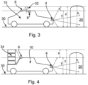
- FIG. 3 shows a vehicle 10 approaching an obstacle 20 in accordance with an embodiment of this disclosure.
- the approaching obstacle 20 has a height h.
- the heigh h corresponds to a clearance height from the ground 30.
- the height h may be the height of an underside of a tree branch, or the height of the underside of low bridge or gantry or road sign from the ground 30.
- FIG. 3 again shows the first sensor 6 and the second sensor 4 of the vehicle 10 as well as the sunroof or window control unit 8.
- the vehicle 10 has a static height component y and a non-static height component x.
- the first sensor 6 may be operable to determine the height z.
- the first sensor 6 may detect the new total height z of the vehicle according to the height of the passengers head 32 above the ground 30 and accordingly may evaluate a new value of the total height z of the vehicle 10 and communicate this actual value to the controller 2.
- the system may anticipate the possible new total height z (or lateral dimension) of the vehicle 10 in the event that the passenger 32 were to extend their head through the sunroof or window of the vehicle 10, albeit that at that moment the passenger 32 has not (yet) placed their head through the sunroof or window (e.g. the sunroof or window of the vehicle 10 is currently closed). This may be achieved either by the first sensor 6 reporting a value of z that includes the static height y plus an anticipated possible change (x) in the total height z in the event that the passenger 32 actually goes ahead and places their head through the sunroof or window.
- the first sensor 6 may simply report the actual present value of z, and anticipated changes (x) in the total height (for example, if the passenger 32 actually goes ahead and places their head through the sunroof or window) may be factored in at the controller 2, as part of the determination of whether a collision is possible.
- the first sensor 6 is operable to communicate the total height z of the vehicle to the controller 2 so that the comparison of the total height z with the height h of the approaching obstacle 20 may be performed.
- the second sensor 4 may need to determine the value of h of the approaching obstacle 20 at a given distance. It would be appreciated that this distance may vary according to the speed of the vehicle 10. A typical value for the distance from the approaching obstacle 20 at which the height h needs to be determined would be around 50-150 meters although, again, it will be appreciated that this distance may vary according to the specific situation.
- Figure 4 shows a vehicle 10 encountering an approaching obstacle 20 in accordance with another embodiment of this disclosure.
- the embodiment shown in Figure 4 is similar to the embodiment shown in Figure 3 , except that in this embodiment, the deviation of the total height z of the vehicle 10 from the nominal static height y of the vehicle 10 results from the mounting of a load 34 (for instance, luggage or other objects) upon the vehicle 10, where the load 34 extends beyond the roof of the vehicle 10.
- the load 34 may have a static component x which extends above the nominal height y.
- the additional height of the load 34 beyond the nominal static height y of the vehicle 10 represents an additional increase in the total height of the vehicle z.
- the height of the load 34 may change in real time if the load 34 is not securely mounted upon the vehicle 10.
- the first sensor 6 is operable to observe the height difference x produced by the load 34 and communicate the value of the total height z of the vehicle 10 to the controller 2, typically in real time. Anticipated changes may also be factored in, as noted above.
- the value of the total height z of the vehicle 10 may again be communicated to the controller 2 so that the comparison of the total height z of the vehicle 10 with the height h of the approaching obstacle 20 may be performed.
- the total height z of the vehicle 10, actual or anticipated may thus be monitored in real time and any changes in the total height z of the vehicle 10 may be communicated to the controller 2.
- the first sensor 6 is operable to monitor the total height of the vehicle 10 by periodically sensing the height of the vehicle 10 at regular time intervals.
- the time intervals may be 0.1 seconds, 0.5 seconds, 1 second or any other suitable time interval. When shorter time intervals are used, this may allow the collision prevention system of this disclosure to react more quickly to real time changes in the total height z of the vehicle 10, although this may come at the cost of increased processing overhead.
- Figures 3 and 4 have been explained in relation to height, it will be appreciated that the same principles may be applied to other dimensions such as a lateral dimension of the vehicle and a lateral dimension of the approaching obstacle.
- Figure 5 shows a collision prevention method 100 according to an embodiment of this disclosure.
- the method 100 in this embodiment includes a number of different branches, starting at steps 102, 112, 122. Note that these branches may be performed in parallel.
- a first branch of the method 100 starts at step 102.
- the first branch corresponds to the operation of the second sensor 4 of the vehicle 10.
- step 104 data from the second sensor 4 may be processed and then in step 106, the height h of an approaching obstacle may be determined from the data processed in step 104.
- this first branch of the method 100 may continually return to step 104 to process more data from the second sensor 4. In this way, any changes in the height h may be detected, and the heights of newly approaching objects may also be detected and determined.
- a second branch of the method 100 starts at step 112.
- the second branch corresponds to the operation of the first sensor 6 of the vehicle 10.
- data from the first sensor 6 may processed.
- the total height of the vehicle 10 may be determined using the data processed in step 114. As already described above, the total height may or may not, at this stage, factor in an anticipated possible change in the height of the vehicle 10. As the total height of the vehicle 10 is determined at step 116, this second branch of the method 100 may continually return to step 114 to process more data from the first sensor 6. In this way, any real time changes in the total height of the vehicle 10 may be detected.
- a comparison of the height h of the approaching obstacle 20 determined in step 106, with the height of the vehicle 10 determined in step 116 is made.
- the total height of the vehicle 10 may be adjusted to include an anticipated, possible total height in the vehicle 10 as noted above, assuming that this has not yet already been factored into the total height reported by the first sensor 6.
- Step 108 may also involve determining a safe height threshold compared to the height h of the approaching obstacle reported by the second sensor 4.
- the safe height threshold may be computed as a percentage of the height h, or (e.g. the safe height threshold may be 80%, 85%, 90%, or 95% etc.
- the threshold may be 100 cm, 50cm, 30cm etc. less than the approaching obstacle height. It is envisaged that the safe height threshold could be programmable, e.g. according to the type of vehicle.
- the comparison of the height of the vehicle 10 with the height of the approaching obstacle 20 may be performed in step 110. For instance, the total height z of the vehicle 10, possibly including any possible, anticipated changes in the total height as described above, may be compared with the safe height threshold described above. The result of this comparison may be reported to step 130, to be described below.
- a third branch of the method 100 starts at step 122.
- the third branch corresponds to the operation of the controller 2 and any vehicle electronic components 50 of the kind described above in relation to Figure 2 .
- one of the possible collision prevention actions that may be performed is the prevention of the opening of the sunroof or window if it is determined in step 110 that, for example, a passenger putting their head through the sunroof or window of the vehicle may cause the total height of the vehicle 10 to meet or exceed the safe height threshold. Accordingly, if the sunroof or window is determined in step 124 to be currently closed, the method 100 may pass to step 128.
- step 128 a determination is made by the controller 2 as to whether there has been a user (driver, passenger%) request to open the sunroof or window.
- This user request may correspond to a request 48 of the kind described above in relation to Figure 2 .
- step 1208 If, in step 128, it is determined that no such user request has been received, then the method 100 may loop back to step 128. In this way, the controller may periodically monitor for any user requests 48 to open the sunroof or window. On the other hand, if it is determined in step 128 that there is a user request to open the sunroof or window, the method 100 may pass to step 130.
- the parts of the method 100 shown in box 160 in Figure 5 correspond to the processing of a user request to open the sunroof or window, and the performance of a collision prevention action involving denying the user request to open the sunroof or window, if this may cause a collision (e.g. were a passenger to put their head through the open sunroof or window).
- step 130 the outcome of the determination made in step 110 is received in conjunction with the indication from step 128 that there has been a request to open the sunroof or window.
- step 140 a determination is made as to whether it is safe to allow the sunroof or window to be opened. In particular, if the determination in step 110 indicated that a collision is possible (e.g. that the anticipated change x in height z associated with a passenger possibly putting their head through the open sunroof or window may lead to a collision), then the method 100 may pass to step 154.
- a collision prevention action may be taken.
- the collision prevention action may involve denying the user request 48 to open the sunroof or window of the vehicle 10. This may, for instance, be implemented by disabling the in-vehicle controls which operate the sunroof or window. It is also envisaged that the collision prevention action may involve applying the brakes of the vehicle 10 and/or generating an collision alert for a driver of the vehicle 10. The alert may, for instance, be an audible and/or visual alert.
- the method 100 may be at step 156.
- step 140 if at step 140 it is determined that it is safe to open the sunroof or window (e.g. the height h of any approaching obstacles is high enough that no collision would occur if a passenger were to put their head through the open sunroof or window, or if no approaching obstacles have been detected), then the method 100 may pass to step 150.
- the sunroof or window e.g. the height h of any approaching obstacles is high enough that no collision would occur if a passenger were to put their head through the open sunroof or window, or if no approaching obstacles have been detected
- step 150 it is determined that no collision prevention action is required and, consequently, at step 152, the controller 2 allows the sunroof or window to be opened.
- This may, for instance, be implemented by the controller signaling a sunroof or window control unit 50A of the kind shown in Figure 2 to open the sunroof or window.
- step 152 the method 100 may loop back to step 124.
- Figure 6 shows a collision prevention method 200 according to another embodiment of this disclosure.
- the method 200 in this embodiment includes a number of different branches, starting at steps 202, 212, 222. Note that these branches may be performed in parallel.
- Figure 6 is similar to Figure 5 , except that Figure 6 shows in more detail the actions which may be taken if it is determined in step 124 that the sunroof or window is already open. Accordingly, the following steps in Figure 6 correspond to the following steps in Figure 5 and the description of these steps will not be repeated here:
- step 226 in Figure 6 (which corresponds to step 128 in Figure 5 ) is reached if, in step 224, it is determined that the sunroof or window is currently closed. Note that in step 226 of Figure 6 , if it determined that there has been a user request to open the sunroof or window, then the method 200 may proceed as described above in relation to the steps in box 160 in Figure 5 .
- step 224 if it is determined in step 224 that the sunroof or window is currently open, then the method 200 may pass to step 230.
- the parts of the method 200 shown in box 260 in Figure 6 correspond to the performance of a collision prevention action involving applying a brake of the vehicle and/or producing a collision alert for a driver of the vehicle.
- step 230 the outcome of the determination made in step 210 is received in conjunction with the indication from step 224 that the sunroof or window is currently open. Unlike in the embodiment of Figure 5 , since the sunroof or window is already open, the option to prevent opening of the sunroof or window does not exist. In this embodiment nevertheless, the controller 2 has the option to perform a collision prevention action involving applying a brake of the vehicle 10 and/or producing a collision alert for a driver of the vehicle 10.
- step 232 a determination is made as to whether a collision may occur. This determination may be based on the determination in step 210, which indicated that a collision is possible (e.g. that the anticipated change x in height z associated with a passenger possibly putting their head through the open sunroof or window may lead to a collision).
- step 232 If, in step 232, it is determined that no collision is possible (e.g. because there are no approaching obstacles or because the height h of the obstacle is such that the safe height threshold is not met or exceeded), the method 200 may loop back to step 230. In this way, the method 200 may continue to monitor for possible collisions.
- step 232 it is determined that a collision is possible, the method 200 may pass to step 234.
- step 234 the controller 2 may determine that a collision prevention action is required.
- the controller 2 may implement the collision prevention action.
- the collision prevention action may involve applying the brakes of the vehicle.
- the controller 2 may, for instance, send a command signal to a brake control unit 50B of the vehicle 10 (as described in Figure 2 ) to apply the brakes of the vehicle 10.
- the controller 2 may also implement the collision prevention action involving producing a collision alert for a driver of the vehicle 10.
- the alert may, for instance, be an audible alert (such as an alarm sounds or pre-recorded verbal warning) and/or visual alert (such as a warning light or symbol appearing on the dashboard of the vehicle).
- the method 200 may end at step 238.
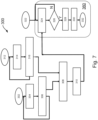
- Figure 7 shows a collision prevention method 300 according to a further embodiment of this disclosure.
- the method 300 in this embodiment includes a number of different branches, starting at steps 302, 312, 322. Note that these branches may be performed in parallel.
- Figure 7 is similar to Figures 5 and 6 , except that Figure 7 involves the application of the brakes of the vehicle and/or the production of a collision alert for a driver of the vehicle, without necessarily involving the operation of the sunroof or window of the vehicle. Accordingly, the following steps in Figure 7 correspond to the following steps in Figure 5 and the description of these steps will not be repeated here:
- a third branch of the method 300 in Figure 7 may start at step 322.
- the parts of the method 300 shown in box 360 in Figure 7 correspond to the performance of a collision prevention action involving applying a brake of the vehicle and/or producing a collision alert for a driver of the vehicle.
- the present embodiment is generic in the sense that the collision prevention action may include any of the application of the brakes of the vehicle 10, the production of collision alert for a driver of the vehicle 10, and/or the denial of a user request 48 (such as a request to open a sunroof or window of the vehicle 10.
- step 324 the outcome of the determination made in step 310 is received by the controller 2.
- step 324 may, in some embodiments, involve determining whether a sunroof or window of the vehicle is open and then tailoring the collision prevention action accordingly.
- the embodiment of Figure 7 may be applied to embodiments of the kind described above in relation to Figure 4 , in which the height of the vehicle is associated with a load 34 placed on the vehicle. Nevertheless, the method 300 may still factor in anticipated possible changes in the height of the load, as noted previously.
- step 326 the controller may determine whether a collision is possible, based upon the indication from step 310 received by the controller in step 324. If, in step 326, it is determined that a collision is not possible (e.g. because there are no approaching obstacles or because the height h of the obstacle is such that the safe height threshold is not met or exceeded), then the method 300 may loop back to 324. In this way, the method 300 may continue to monitor for possible collisions.
- step 326 it is determined that a collision is possible, the method 300 may pass to step 328.
- step 328 the controller 2 may determine that a collision prevention action is required.
- the controller 2 may implement the collision prevention action.
- the collision prevention action may involve applying the brakes of the vehicle.
- the controller 2 may, for instance, send a command signal to a brake control unit 50B of the vehicle 10 (as described in Figure 2 ) to apply the brakes of the vehicle 10.
- the controller 2 may also implement the collision prevention action involving producing a collision alert for a driver of the vehicle 10.
- the alert may, for instance, be an audible alert (such as an alarm sounds or pre-recorded verbal warning) and/or visual alert (such as a warning light or symbol appearing on the dashboard of the vehicle).
- the method 300 may end at step 332.
- Figures 5 to 7 have been explained in relation to height, it will be appreciated that the same principles may be applied to other dimensions such as a lateral dimension of the vehicle and a lateral dimension of the approaching obstacle.
- a vehicle including a collision prevention system of the kind described above.
- a collision prevention method for a vehicle includes a first sensor operable to monitor a dimension (e.g. height) of the vehicle.
- the system also includes a second sensor for detecting a dimension (e.g. height) of an approaching obstacle.
- the system further includes a controller couplable to the first sensor and the second sensor.
- the controller is operable to compare the dimension of the vehicle monitored by the first sensor with the dimension of the approaching obstacle detected by the second sensor.
- the controller is also operable to, in response to a determination that the comparison of the dimension of the vehicle with the dimension of the approaching obstacle indicates a collision between the vehicle and the obstacle is possible, perform a collision prevention action.
Landscapes
- Engineering & Computer Science (AREA)
- Remote Sensing (AREA)
- Radar, Positioning & Navigation (AREA)
- Automation & Control Theory (AREA)
- Mechanical Engineering (AREA)
- Transportation (AREA)
- Physics & Mathematics (AREA)
- Computer Networks & Wireless Communication (AREA)
- General Physics & Mathematics (AREA)
- Human Computer Interaction (AREA)
- Mathematical Physics (AREA)
- Electromagnetism (AREA)
- Traffic Control Systems (AREA)
Abstract
Description
- The present specification relates to a system and method for a vehicle.
- Height restrictions on roads are in place to prevent vehicles having a certain height from colliding with overhead obstructions such as a low bridge or gantry. Generally, the height of a vehicle may be static and known. In this case, a driver of the vehicle may simply avoid taking routes which involve height limits with which the vehicle does not comply.
- Aspects of the present disclosure are set out in the accompanying independent and dependent claims. Combinations of features from the dependent claims may be combined with features of the independent claims as appropriate and not merely as explicitly set out in the claims.
- According to an aspect of the present disclosure, there is provided a collision prevention system for a vehicle, the system comprising:
- a first sensor operable to monitor a dimension of the vehicle;
- a second sensor for detecting a dimension of an approaching obstacle; and
- a controller couplable to the first sensor and the second sensor;
- compare the dimension of the vehicle monitored by the first sensor with the dimension of the approaching obstacle detected by the second sensor; and
- in response to a determination that the comparison of the dimension of the vehicle with the dimension of the approaching obstacle indicates a collision between the vehicle and the obstacle is possible, performing a collision prevention action.
- According to another aspect of the present disclosure, there is provided a collision prevention method for a vehicle, the method comprising:
- monitoring a dimension of the vehicle;
- detecting a dimension of an approaching obstacle; and
- comparing the dimension of the vehicle with the dimension of the approaching obstacle; and
- in response to a determination that the comparison of the dimension of the vehicle with the dimension of the approaching obstacle indicates a collision between the vehicle and the obstacle is possible, performing a collision prevention action.
- A collision avoidance system or method according to the present disclosure may allow collisions associated with the dimension of the vehicle to be avoided.
- The comparison of the dimension of the vehicle with the dimension of the approaching obstacle may, for instance, be based upon real-time changes in the dimension of the vehicle.
- The determination may include determining whether the dimension of the vehicle monitored by the first sensor exceeds a safe dimension threshold compared to the dimension of the approaching obstacle. The safe dimension threshold may be expressed as a percentage of the obstacle dimension (e.g. the safe dimension threshold may be 80%, 85%, 90%, or 95% etc. of the approaching obstacle dimension), or may be associated with an absolute difference between the dimension of the vehicle and the dimension of the approaching obstacle (e.g. the threshold may be 100 cm, 50cm, 30cm etc. less than the approaching obstacle dimension). It is envisaged that the safe dimension threshold could be programmable, e.g. according to the type of vehicle.
- The first sensor may be operable to monitor the dimension of the vehicle by periodically sensing the dimension of the vehicle at regular time intervals (e.g. the time interval may be 0.1 seconds, 0.5 seconds, 1 second, or in the range 2-10 seconds etc.).
- The dimension of the vehicle may be a total dimension including a dimension of a load mounted on the vehicle and/or of a passenger protruding from (e.g. a window or sunroof) the vehicle.
- The collision prevention action may include applying a brake of the vehicle.
- The collision prevention action may include generating an collision alert for a driver of the vehicle. The alert may, for instance, be an audible and/or visual alert.
- The dimension of the vehicle (e.g. monitored by the first sensor) may be a height of the vehicle. The dimension of the approaching obstacle (e.g. detected by the second sensor) may be a height of the approaching obstacle. Accordingly, the safe dimension threshold may also be a safe height threshold.
- The collision prevention action may include a pre-emptive collision prevention action to prevent a dimension of the vehicle increasing beyond a safe dimension threshold associated with the dimension of the approaching obstacle as the vehicle approaches the obstacle. This may allow real time changes in the dimension of the vehicle which may cause a collision to be prevented.
- The pre-emptive collision prevention action may include denying a driver or passenger request to open the window or sunroof of the vehicle.
- The first sensor and/or the second sensor each comprise:
- a camera;
- an ultrasound sensor;
- a RADAR sensor; and/or
- a LIDAR sensor.
- According to a further aspect of the present disclosure, there is provided a vehicle comprising the collision prevention system set out above.
- Embodiments of this disclosure will be described hereinafter, by way of example only, with reference to the accompanying drawings in which like reference signs relate to like elements and in which:
-
Figure 1 shows a vehicle according to an embodiment of this disclosure; -
Figure 2 shows a system according to another embodiment of this disclosure; -
Figure 3 shows a vehicle encountering an obstacle, according to a further embodiment of this disclosure; -
Figure 4 shows a vehicle encountering an obstacle, according to another embodiment of this disclosure; -
Figure 5 shows a method according to a further embodiment of this disclosure; -
Figure 6 shows a method according to another embodiment of this disclosure; and -
Figure 7 shows a method according to a further embodiment of this disclosure. - Embodiments of this disclosure are described in the following with reference to the accompanying drawings.
- As described herein, the dimension of a vehicle is monitored by a sensor and compared with a dimension of an approaching obstacle detected by another sensor. In the following embodiments, the dimension of the vehicle monitored by the first sensor is a height of the vehicle and the dimension of the approaching obstacle detected by the second sensor is a height of the approaching obstacle. However, it will be appreciated that embodiments of this disclosure may also be applied to other dimensions of the vehicle and the approaching obstacle. For instance, the dimension of the vehicle monitored by the first sensor may be a lateral dimension of the vehicle (e.g. in a direction substantially parallel to the ground and substantially perpendicular to a direction of travel of the vehicle). Similarly, the dimension of the approaching obstacle detected by the second sensor may be a lateral dimension associated with the lateral dimension of the vehicle monitored by the first sensor.
-
Figure 1 shows avehicle 10 according to an embodiment of this disclosure. Thevehicle 10 may, for instance be a car, truck, lorry or any other kind of road vehicle. - The
vehicle 10 includes afirst sensor 6. Thefirst sensor 6 is operable to monitor a height of thevehicle 10. As noted above, the dimension monitored by the first sensor may not be the height of the vehicle but may instead be a lateral dimension of the vehicle (e.g. see thelateral dimensions Figure 1 ). - The
first sensor 6 may be located in any suitable position within or upon thevehicle 10. For example thefirst sensor 6 may be located on a roof, side, or other exterior part of thevehicle 10. Thefirst sensor 6 may comprise any suitable sensor for monitoring the dimension (height, lateral dimension etc.) of thevehicle 10, for example, thefirst sensor 6 may comprise a camera, an ultrasound sensor, a RADAR (Radio Detection and Ranging) sensor, or a LIDAR (Light Detection and Ranging) sensor. - The
vehicle 10 also includes asecond sensor 4. The second sensor is operable to detect an approaching obstacle. In particular, thesecond sensor 4 is operable to detect a dimension (e.g. height, lateral dimension such as width) of the approaching obstacle. The dimension (height, in this example) of the approaching obstacle may represent a clearance dimension (height, in this example), above which collisions may, or will, occur. - The approaching obstacle may, for example, be an overhanging obstacle such as a low bridge or gantry, a tunnel, a road sign or a tree branch.
- The
second sensor 4 may, for example, be located toward the front of thevehicle 10. Thesecond sensor 4 may be any suitable sensor for determining the dimension (height, in this example) of the approaching obstacle. For instance, the second sensor may comprise a RADAR sensor a LIDAR sensor, an ultrasound sensor or a camera. - The
vehicle 10 also includes acontroller 2. Thecontroller 2 may be coupled to thefirst sensor 6 and thesecond sensor 4 by, for example, a data/control signal bus 11. The bus may be part of a Car Area Network (CAN). The bus may comprise a wired and/or a wireless connection. As will be described in more detail below, thecontroller 2 is operable to receive signals from thefirst sensor 6 and thesecond sensor 4, those signals indicating the dimension (height, in this example) of thevehicle 10 monitored by thefirst sensor 6 and the dimension (height, in this example) of the approaching obstacle detected by thesecond sensor 4. - The
controller 2 is operable to compare the dimension (height, in this example) of thevehicle 10 monitored by thefirst sensor 6 with the dimension (height, in this example) of the approaching obstacle detected by thesecond sensor 4 and, in response to that comparison, to determine whether a collision between the vehicle and the obstacle is possible. If it is determined that a collision is possible, thecontroller 2 is further operable to perform a collision prevention action. Types of collision prevention action may, for example, include: - applying the brakes of the vehicle to slow the vehicle down (for example, to a stop),
- producing an audible or visual collision alert to alert the driver of the vehicle of the impending collision; and/or
- a pre-emptive collision prevention action (such as disabling a sunroof or window opening mechanism of the vehicle to prevent a passenger of the vehicle protruding from the window or sunroof until the vehicle has cleared or passed beneath the approaching obstacle).
- The
vehicle 10 shown inFigure 1 further includes one ormore control units 8. Thesecontrol units 8 may be, for example, for controlling a sunroof or window of the vehicle as noted above. The one ormore control units 8 may also be coupled to thecontroller 2 via thebus 11. -
Figure 2 shows a schematic of the functional blocks of a collision prevention system for a vehicle of the kind shown inFigure 1 , according to an embodiment of this disclosure.Figure 2 shows that the system can include a plurality ofsensors 4. For instance, inFigure 2 , thesensor 40A may represent thefirst sensor 6 and thesensor 40B may represent thesecond sensor 4. It is envisaged that further sensors may be provided in the plurality ofsensors 40, other than thefirst sensor 6 and thesecond sensor 4. - In this embodiment, the
controller 2 includesfunctional blocks functional block 42 may act to receive the signals from the plurality ofsensors 40 such as the signals relating to the monitored dimension (height, in this example) of thevehicle 10 and the detected dimension (height, in this example) of the approaching obstacle as noted above in respect ofFigure 1 . The signals received by thefunctional block 42 may then be passed to adata processing block 44, in which the aforementioned comparison of the dimension (height, in this example) of thevehicle 10 monitored by thefirst sensor 6 with the dimension (height, in this example) of the approaching obstacle detected by thesecond sensor 4 may be performed. The result of this comparison may then be passed to acentral processing unit 46. Thecentral processing unit 46 may then take action in response to the comparison performed by thefunctional block 44. In particular, thecentral processing unit 46 may act to implement a collision prevention action as described herein. - The embodiment shown in
Figure 2 also includes a number ofelectronic components 50 of thevehicle 10. Examples of such electronic components may include a sunroof orwindow control unit 50A of thevehicle 10, abrake control unit 50B of thevehicle 10 and/or analert unit 50C of thevehicle 10, for producing an audible or visual alert for the driver of thevehicle 10. Thecentral processing unit 46 may be coupled to the vehicle electronic components 50 (e.g., using thebus 11 shown inFigure 1 ) and may be operable to send appropriate signals to theelectronic components 50 for implementing one or more collision prevention actions in the event that the comparison result received from thefunctional block 44 indicates that a collision between thevehicle 10 and the approaching obstacle is possible. - In
Figure 2 , block 48 represents a user request. Theuser request 48 may, for example, be a request to open a window or sunroof of thevehicle 10. The incorporation of theuser request 48 into a method according to an embodiment of this disclosure will be described in more detail below in relation to, for example,Figures 5 to 7 . -
Figure 3 shows avehicle 10 approaching anobstacle 20 in accordance with an embodiment of this disclosure. The approachingobstacle 20 has a height h. The heigh h corresponds to a clearance height from theground 30. Accordingly, for example, the height h may be the height of an underside of a tree branch, or the height of the underside of low bridge or gantry or road sign from theground 30. -
Figure 3 again shows thefirst sensor 6 and thesecond sensor 4 of thevehicle 10 as well as the sunroof orwindow control unit 8. - In this embodiment, the
vehicle 10 has a static height component y and a non-static height component x. The total height of thevehicle 10 may be denoted as z where z = y + x. - According to an embodiment, in operation, the
first sensor 6 may be operable to determine the height z. - This may, for instance, be achieved by knowledge of the static height component y, to which the
first sensor 6 may add the value of x based over upon actual observations of dynamic changes (represented by x) in the total height z of thevehicle 10 or by possible changes that may occur in x as thevehicle 10 approaches theobstacle 20. By way of example, if apassenger 32 of thevehicle 10 were to place their head of other parts of their body through the sunroof or window of thevehicle 10, the total height of the vehicle z may change. It will be appreciated that similar considerations may apply to a lateral dimension of the vehicle, should the passenger put their head through an open side window of the vehicle. In this example, thefirst sensor 6 may detect the new total height z of the vehicle according to the height of the passengers head 32 above theground 30 and accordingly may evaluate a new value of the total height z of thevehicle 10 and communicate this actual value to thecontroller 2. - In another example, the system may anticipate the possible new total height z (or lateral dimension) of the
vehicle 10 in the event that thepassenger 32 were to extend their head through the sunroof or window of thevehicle 10, albeit that at that moment thepassenger 32 has not (yet) placed their head through the sunroof or window (e.g. the sunroof or window of thevehicle 10 is currently closed). This may be achieved either by thefirst sensor 6 reporting a value of z that includes the static height y plus an anticipated possible change (x) in the total height z in the event that thepassenger 32 actually goes ahead and places their head through the sunroof or window. Alternatively, thefirst sensor 6 may simply report the actual present value of z, and anticipated changes (x) in the total height (for example, if thepassenger 32 actually goes ahead and places their head through the sunroof or window) may be factored in at thecontroller 2, as part of the determination of whether a collision is possible. - In either event, the
first sensor 6 is operable to communicate the total height z of the vehicle to thecontroller 2 so that the comparison of the total height z with the height h of the approachingobstacle 20 may be performed. - In order to allow sufficient time for the collision prevention action to be performed, the
second sensor 4 may need to determine the value of h of the approachingobstacle 20 at a given distance. It would be appreciated that this distance may vary according to the speed of thevehicle 10. A typical value for the distance from the approachingobstacle 20 at which the height h needs to be determined would be around 50-150 meters although, again, it will be appreciated that this distance may vary according to the specific situation. -
Figure 4 shows avehicle 10 encountering an approachingobstacle 20 in accordance with another embodiment of this disclosure. The embodiment shown inFigure 4 is similar to the embodiment shown inFigure 3 , except that in this embodiment, the deviation of the total height z of thevehicle 10 from the nominal static height y of thevehicle 10 results from the mounting of a load 34 (for instance, luggage or other objects) upon thevehicle 10, where theload 34 extends beyond the roof of thevehicle 10. In this sense, theload 34 may have a static component x which extends above the nominal height y. Nevertheless, it will be appreciated that the additional height of theload 34 beyond the nominal static height y of thevehicle 10 represents an additional increase in the total height of the vehicle z. It may also be appreciated that the height of theload 34 may change in real time if theload 34 is not securely mounted upon thevehicle 10. Again, thefirst sensor 6 is operable to observe the height difference x produced by theload 34 and communicate the value of the total height z of thevehicle 10 to thecontroller 2, typically in real time. Anticipated changes may also be factored in, as noted above. The value of the total height z of thevehicle 10 may again be communicated to thecontroller 2 so that the comparison of the total height z of thevehicle 10 with the height h of the approachingobstacle 20 may be performed. - According to embodiments of this disclosure, the total height z of the
vehicle 10, actual or anticipated, may thus be monitored in real time and any changes in the total height z of thevehicle 10 may be communicated to thecontroller 2. In some embodiments, thefirst sensor 6 is operable to monitor the total height of thevehicle 10 by periodically sensing the height of thevehicle 10 at regular time intervals. By way of example only, the time intervals may be 0.1 seconds, 0.5 seconds, 1 second or any other suitable time interval. When shorter time intervals are used, this may allow the collision prevention system of this disclosure to react more quickly to real time changes in the total height z of thevehicle 10, although this may come at the cost of increased processing overhead. - Although
Figures 3 and 4 have been explained in relation to height, it will be appreciated that the same principles may be applied to other dimensions such as a lateral dimension of the vehicle and a lateral dimension of the approaching obstacle. -
Figure 5 shows acollision prevention method 100 according to an embodiment of this disclosure. Themethod 100 in this embodiment includes a number of different branches, starting atsteps - A first branch of the
method 100 starts atstep 102. The first branch corresponds to the operation of thesecond sensor 4 of thevehicle 10. Instep 104, data from thesecond sensor 4 may be processed and then instep 106, the height h of an approaching obstacle may be determined from the data processed instep 104. As the height h of the approaching object is determined atstep 106, this first branch of themethod 100 may continually return to step 104 to process more data from thesecond sensor 4. In this way, any changes in the height h may be detected, and the heights of newly approaching objects may also be detected and determined. - A second branch of the
method 100 starts atstep 112. The second branch corresponds to the operation of thefirst sensor 6 of thevehicle 10. Atstep 114, data from thefirst sensor 6 may processed. Atstep 116, the total height of thevehicle 10 may be determined using the data processed instep 114. As already described above, the total height may or may not, at this stage, factor in an anticipated possible change in the height of thevehicle 10. As the total height of thevehicle 10 is determined atstep 116, this second branch of themethod 100 may continually return to step 114 to process more data from thefirst sensor 6. In this way, any real time changes in the total height of thevehicle 10 may be detected. - At
steps obstacle 20 determined instep 106, with the height of thevehicle 10 determined instep 116 is made. For instance, instep 108, the total height of thevehicle 10 may be adjusted to include an anticipated, possible total height in thevehicle 10 as noted above, assuming that this has not yet already been factored into the total height reported by thefirst sensor 6. Step 108 may also involve determining a safe height threshold compared to the height h of the approaching obstacle reported by thesecond sensor 4. By way of example, the safe height threshold may be computed as a percentage of the height h, or (e.g. the safe height threshold may be 80%, 85%, 90%, or 95% etc. of the approaching obstacle height), or may be associated with an absolute difference between the height of thevehicle 10 and the height of the approaching obstacle (e.g. the threshold may be 100 cm, 50cm, 30cm etc. less than the approaching obstacle height). It is envisaged that the safe height threshold could be programmable, e.g. according to the type of vehicle. The comparison of the height of thevehicle 10 with the height of the approachingobstacle 20 may be performed instep 110. For instance, the total height z of thevehicle 10, possibly including any possible, anticipated changes in the total height as described above, may be compared with the safe height threshold described above. The result of this comparison may be reported to step 130, to be described below. - A third branch of the
method 100 starts atstep 122. The third branch corresponds to the operation of thecontroller 2 and any vehicleelectronic components 50 of the kind described above in relation toFigure 2 . - In this embodiment, at step 124 a determination is made by the
controller 2 as to whether the sunroof or window on thevehicle 10 is open. WhileFigure 5 is explained here in relation to a sunroof or window of the vehicle, it will be appreciated that the method ofFigure 5 may also be applied to a window of thevehicle 10. If the sunroof or window is determined to be open, then themethod 100 may pass to step 126. Step 126 may involve the performance of a collision prevention action such as the application of the brakes of thevehicle 10 and/or the production of a warning alert to the driver of thevehicle 10, in response to a determination instep 110 that a collision is possible. For a further description of the actions which may be taken if it is determined instep 124 that the sunroof or window is already open, seeFigure 6 . - On the other hand, in this embodiment, one of the possible collision prevention actions that may be performed is the prevention of the opening of the sunroof or window if it is determined in
step 110 that, for example, a passenger putting their head through the sunroof or window of the vehicle may cause the total height of thevehicle 10 to meet or exceed the safe height threshold. Accordingly, if the sunroof or window is determined instep 124 to be currently closed, themethod 100 may pass to step 128. - In
step 128, a determination is made by thecontroller 2 as to whether there has been a user (driver, passenger...) request to open the sunroof or window. This user request may correspond to arequest 48 of the kind described above in relation toFigure 2 . - If, in
step 128, it is determined that no such user request has been received, then themethod 100 may loop back to step 128. In this way, the controller may periodically monitor for anyuser requests 48 to open the sunroof or window. On the other hand, if it is determined instep 128 that there is a user request to open the sunroof or window, themethod 100 may pass to step 130. - The parts of the
method 100 shown inbox 160 inFigure 5 correspond to the processing of a user request to open the sunroof or window, and the performance of a collision prevention action involving denying the user request to open the sunroof or window, if this may cause a collision (e.g. were a passenger to put their head through the open sunroof or window). - In
step 130, the outcome of the determination made instep 110 is received in conjunction with the indication fromstep 128 that there has been a request to open the sunroof or window. - In
step 140, a determination is made as to whether it is safe to allow the sunroof or window to be opened. In particular, if the determination instep 110 indicated that a collision is possible (e.g. that the anticipated change x in height z associated with a passenger possibly putting their head through the open sunroof or window may lead to a collision), then themethod 100 may pass to step 154. - In
step 154, a collision prevention action may be taken. In this embodiment, the collision prevention action may involve denying theuser request 48 to open the sunroof or window of thevehicle 10. This may, for instance, be implemented by disabling the in-vehicle controls which operate the sunroof or window. It is also envisaged that the collision prevention action may involve applying the brakes of thevehicle 10 and/or generating an collision alert for a driver of thevehicle 10. The alert may, for instance, be an audible and/or visual alert. - The
method 100 may be atstep 156. - On the other hand, if at
step 140 it is determined that it is safe to open the sunroof or window (e.g. the height h of any approaching obstacles is high enough that no collision would occur if a passenger were to put their head through the open sunroof or window, or if no approaching obstacles have been detected), then themethod 100 may pass to step 150. - At
step 150, it is determined that no collision prevention action is required and, consequently, atstep 152, thecontroller 2 allows the sunroof or window to be opened. This may, for instance, be implemented by the controller signaling a sunroof orwindow control unit 50A of the kind shown inFigure 2 to open the sunroof or window. - Following
step 152, themethod 100 may loop back to step 124. -
Figure 6 shows acollision prevention method 200 according to another embodiment of this disclosure. Themethod 200 in this embodiment includes a number of different branches, starting atsteps - Note the
Figure 6 is similar toFigure 5 , except thatFigure 6 shows in more detail the actions which may be taken if it is determined instep 124 that the sunroof or window is already open. Accordingly, the following steps inFigure 6 correspond to the following steps inFigure 5 and the description of these steps will not be repeated here: - the
steps method 200 inFigure 6 correspond to thesteps method 100 inFigure 5 , respectively; - the
steps method 200 inFigure 6 correspond to thesteps method 100 inFigure 5 , respectively; -
steps method 200 inFigure 6 correspond tosteps method 100 inFigure 5 , respectively; and -
steps method 200 inFigure 6 correspond tosteps method 100 inFigure 5 , respectively. - As described previously,
step 226 inFigure 6 (which corresponds to step 128 inFigure 5 ) is reached if, instep 224, it is determined that the sunroof or window is currently closed. Note that instep 226 ofFigure 6 , if it determined that there has been a user request to open the sunroof or window, then themethod 200 may proceed as described above in relation to the steps inbox 160 inFigure 5 . - On the other hand, if it is determined in
step 224 that the sunroof or window is currently open, then themethod 200 may pass to step 230. - The parts of the
method 200 shown inbox 260 inFigure 6 correspond to the performance of a collision prevention action involving applying a brake of the vehicle and/or producing a collision alert for a driver of the vehicle. - In
step 230, the outcome of the determination made instep 210 is received in conjunction with the indication fromstep 224 that the sunroof or window is currently open. Unlike in the embodiment ofFigure 5 , since the sunroof or window is already open, the option to prevent opening of the sunroof or window does not exist. In this embodiment nevertheless, thecontroller 2 has the option to perform a collision prevention action involving applying a brake of thevehicle 10 and/or producing a collision alert for a driver of thevehicle 10. - In
step 232, a determination is made as to whether a collision may occur. This determination may be based on the determination instep 210, which indicated that a collision is possible (e.g. that the anticipated change x in height z associated with a passenger possibly putting their head through the open sunroof or window may lead to a collision). - If, in
step 232, it is determined that no collision is possible (e.g. because there are no approaching obstacles or because the height h of the obstacle is such that the safe height threshold is not met or exceeded), themethod 200 may loop back to step 230. In this way, themethod 200 may continue to monitor for possible collisions. - On the other hand if, in
step 232, it is determined that a collision is possible, themethod 200 may pass to step 234. Instep 234, thecontroller 2 may determine that a collision prevention action is required. - In
step 236, thecontroller 2 may implement the collision prevention action. As described above, the collision prevention action may involve applying the brakes of the vehicle. To implement this, thecontroller 2 may, for instance, send a command signal to abrake control unit 50B of the vehicle 10 (as described inFigure 2 ) to apply the brakes of thevehicle 10. As an alternative, or in addition to the application of the brakes, thecontroller 2 may also implement the collision prevention action involving producing a collision alert for a driver of thevehicle 10. The alert may, for instance, be an audible alert (such as an alarm sounds or pre-recorded verbal warning) and/or visual alert (such as a warning light or symbol appearing on the dashboard of the vehicle). - The
method 200 may end atstep 238. -
Figure 7 shows acollision prevention method 300 according to a further embodiment of this disclosure. Themethod 300 in this embodiment includes a number of different branches, starting atsteps - Note the
Figure 7 is similar toFigures 5 and6 , except thatFigure 7 involves the application of the brakes of the vehicle and/or the production of a collision alert for a driver of the vehicle, without necessarily involving the operation of the sunroof or window of the vehicle. Accordingly, the following steps inFigure 7 correspond to the following steps inFigure 5 and the description of these steps will not be repeated here: - the
steps method 300 inFigure 7 correspond to thesteps method 100 inFigure 5 , respectively; - the
steps method 300 inFigure 7 correspond to thesteps method 100 inFigure 5 , respectively; and -
steps method 300 inFigure 7 correspond tosteps method 100 inFigure 5 , respectively. - A third branch of the
method 300 inFigure 7 may start atstep 322. - As in
Figure 6 , the parts of themethod 300 shown inbox 360 inFigure 7 correspond to the performance of a collision prevention action involving applying a brake of the vehicle and/or producing a collision alert for a driver of the vehicle. However, the present embodiment is generic in the sense that the collision prevention action may include any of the application of the brakes of thevehicle 10, the production of collision alert for a driver of thevehicle 10, and/or the denial of a user request 48 (such as a request to open a sunroof or window of thevehicle 10. - In
step 324, the outcome of the determination made instep 310 is received by thecontroller 2. As describe previously,step 324 may, in some embodiments, involve determining whether a sunroof or window of the vehicle is open and then tailoring the collision prevention action accordingly. However, for the remainder of the description of this embodiment, it will be assumed that the operation of the sunroof or windows is not factored into the determination and performance of a collision prevention action. In that sense, the embodiment ofFigure 7 may be applied to embodiments of the kind described above in relation toFigure 4 , in which the height of the vehicle is associated with aload 34 placed on the vehicle. Nevertheless, themethod 300 may still factor in anticipated possible changes in the height of the load, as noted previously. - In
step 326, the controller may determine whether a collision is possible, based upon the indication fromstep 310 received by the controller instep 324. If, instep 326, it is determined that a collision is not possible (e.g. because there are no approaching obstacles or because the height h of the obstacle is such that the safe height threshold is not met or exceeded), then themethod 300 may loop back to 324. In this way, themethod 300 may continue to monitor for possible collisions. - On the other hand if, at
step 326 it is determined that a collision is possible, themethod 300 may pass to step 328. Instep 328, thecontroller 2 may determine that a collision prevention action is required. - In
step 330, thecontroller 2 may implement the collision prevention action. As described above, the collision prevention action may involve applying the brakes of the vehicle. To implement this, thecontroller 2 may, for instance, send a command signal to abrake control unit 50B of the vehicle 10 (as described inFigure 2 ) to apply the brakes of thevehicle 10. As an alternative, or in addition to the application of the brakes, thecontroller 2 may also implement the collision prevention action involving producing a collision alert for a driver of thevehicle 10. The alert may, for instance, be an audible alert (such as an alarm sounds or pre-recorded verbal warning) and/or visual alert (such as a warning light or symbol appearing on the dashboard of the vehicle). - The
method 300 may end atstep 332. - Although
Figures 5 to 7 have been explained in relation to height, it will be appreciated that the same principles may be applied to other dimensions such as a lateral dimension of the vehicle and a lateral dimension of the approaching obstacle. - According to an embodiment, there may be provided a vehicle including a collision prevention system of the kind described above.
- Accordingly, there has been described a collision prevention system for a vehicle. A collision prevention method for a vehicle. The system includes a first sensor operable to monitor a dimension (e.g. height) of the vehicle. The system also includes a second sensor for detecting a dimension (e.g. height) of an approaching obstacle. The system further includes a controller couplable to the first sensor and the second sensor. The controller is operable to compare the dimension of the vehicle monitored by the first sensor with the dimension of the approaching obstacle detected by the second sensor. The controller is also operable to, in response to a determination that the comparison of the dimension of the vehicle with the dimension of the approaching obstacle indicates a collision between the vehicle and the obstacle is possible, perform a collision prevention action.
- Although particular embodiments of this disclosure have been described, it will be appreciated that many modifications/additions and/or substitutions may be made within the scope of the claims.
Claims (15)
- A collision prevention system for a vehicle, the system comprising:a first sensor operable to monitor a dimension of the vehicle;a second sensor for detecting a dimension of an approaching obstacle; anda controller couplable to the first sensor and the second sensor;wherein the controller is operable to:compare the dimension of the vehicle monitored by the first sensor with the dimension of the approaching obstacle detected by the second sensor; andin response to a determination that the comparison of the dimension of the vehicle with the dimension of the approaching obstacle indicates a collision between the vehicle and the obstacle is possible, performing a collision prevention action.
- The collision prevention system of claim 1, wherein the determination comprises determining whether the dimension of the vehicle monitored by the first sensor exceeds a safe dimension threshold compared to the dimension of the approaching obstacle.
- The collision prevention system of claim 1 or claim 2, wherein the first sensor is operable to monitor the dimension of the vehicle by periodically sensing the dimension of the vehicle at regular time intervals.
- The collision prevention system of any preceding claim, wherein the dimension of the vehicle is a total dimension including a dimension of a load mounted on the vehicle and/or of a passenger protruding from the vehicle.
- The collision prevention system of any preceding claim, wherein the collision prevention action comprises applying a brake of the vehicle and/or generating an collision alert for a driver of the vehicle.
- The collision prevention system of any preceding claim, wherein the dimension of the vehicle monitored by the first sensor comprises a height of the vehicle, and wherein the dimension of the approaching obstacle detected by the second sensor comprises a height of the approaching obstacle.
- The collision prevention system of any preceding claim, wherein the collision prevention action comprises a pre-emptive collision prevention action to prevent a dimension of the vehicle increasing beyond a safe dimension threshold associated with the dimension of the approaching obstacle as the vehicle approaches the obstacle.
- The collision prevention system of claim 7, wherein the pre-emptive collision prevention action comprises denying a driver or passenger request to open the window or sunroof of the vehicle.
- The collision prevention system of any preceding claim, wherein the first sensor and/or the second sensor each comprise:a camera;an ultrasound sensor;a RADAR sensor; and/ora LADAR sensor.
- A vehicle comprising the collision prevention system of any preceding claim.
- A collision prevention method for a vehicle, the method comprising:monitoring a dimension of the vehicle;detecting a dimension of an approaching obstacle; andcomparing the dimension of the vehicle with the dimension of the approaching obstacle; andin response to a determination that the comparison of the dimension of the vehicle with the dimension of the approaching obstacle indicates a collision between the vehicle and the obstacle is possible, performing a collision prevention action.
- The method of claim 11, wherein the dimension of the vehicle is a total dimension including a dimension of a load mounted on the vehicle and/or of a passenger protruding from the vehicle.
- The method of claim 11 or claim 12, wherein the collision prevention action comprises a pre-emptive collision prevention action to prevent a dimension of the vehicle increasing beyond a safe dimension threshold associated with the dimension of the approaching obstacle as the vehicle approaches the obstacle.
- The method of claim 13, wherein the collision prevention action comprises denying a driver or passenger request to open the window or sunroof of the vehicle.
- The method of any of claims 11 to 14, wherein the monitored dimension of the vehicle comprises a height of the vehicle, and wherein the detected dimension of the approaching obstacle comprises a height of the approaching obstacle.
Priority Applications (1)
| Application Number | Priority Date | Filing Date | Title |
|---|---|---|---|
| US18/308,831 US12589736B2 (en) | 2022-05-17 | 2023-04-28 | Collision prevention system and method for a vehicle |
Applications Claiming Priority (1)
| Application Number | Priority Date | Filing Date | Title |
|---|---|---|---|
| IN202211028334 | 2022-05-17 |
Publications (2)
| Publication Number | Publication Date |
|---|---|
| EP4279956A1 true EP4279956A1 (en) | 2023-11-22 |
| EP4279956B1 EP4279956B1 (en) | 2025-04-09 |
Family
ID=82850375
Family Applications (1)
| Application Number | Title | Priority Date | Filing Date |
|---|---|---|---|
| EP22185309.6A Active EP4279956B1 (en) | 2022-05-17 | 2022-07-15 | Collision prevention system and method for a vehicle |
Country Status (2)
| Country | Link |
|---|---|
| US (1) | US12589736B2 (en) |
| EP (1) | EP4279956B1 (en) |
Families Citing this family (1)
| Publication number | Priority date | Publication date | Assignee | Title |
|---|---|---|---|---|
| US20240393454A1 (en) * | 2023-05-24 | 2024-11-28 | Ford Global Technologies, Llc | Obstruction detection for a vehicle |
Citations (3)
| Publication number | Priority date | Publication date | Assignee | Title |
|---|---|---|---|---|
| US20130222592A1 (en) * | 2012-02-24 | 2013-08-29 | Magna Electronics Inc. | Vehicle top clearance alert system |
| US20160297360A1 (en) * | 2015-04-08 | 2016-10-13 | Ford Global Technologies, Llc | Apparatus and method for actively determining height clearance and generating alerts |
| US20210129750A1 (en) * | 2019-11-05 | 2021-05-06 | Frank Nugent | Overhead obstacle detection and avoidance system for vehicles |
Family Cites Families (5)
| Publication number | Priority date | Publication date | Assignee | Title |
|---|---|---|---|---|
| US7052069B2 (en) * | 2004-04-28 | 2006-05-30 | Phyllis Louise Vance | Protective device for a vehicle door |
| EP2008257A2 (en) * | 2006-03-30 | 2008-12-31 | Asher S. Saban | Protecting children and passengers with respect to a vehicle |
| US9488482B2 (en) * | 2013-08-30 | 2016-11-08 | Elwha Llc | Systems and methods for adjusting a contour of a vehicle based on a protrusion |
| CN107237575B (en) | 2017-05-31 | 2018-08-17 | 中国科学院合肥物质科学研究院 | A kind of laser radar intelligence sunroof control system and method |
| US10671862B2 (en) | 2018-01-30 | 2020-06-02 | Wipro Limited | Method and system for detecting obstacles by autonomous vehicles in real-time |
-
2022
- 2022-07-15 EP EP22185309.6A patent/EP4279956B1/en active Active
-
2023
- 2023-04-28 US US18/308,831 patent/US12589736B2/en active Active
Patent Citations (3)
| Publication number | Priority date | Publication date | Assignee | Title |
|---|---|---|---|---|
| US20130222592A1 (en) * | 2012-02-24 | 2013-08-29 | Magna Electronics Inc. | Vehicle top clearance alert system |
| US20160297360A1 (en) * | 2015-04-08 | 2016-10-13 | Ford Global Technologies, Llc | Apparatus and method for actively determining height clearance and generating alerts |
| US20210129750A1 (en) * | 2019-11-05 | 2021-05-06 | Frank Nugent | Overhead obstacle detection and avoidance system for vehicles |
Also Published As
| Publication number | Publication date |
|---|---|
| US12589736B2 (en) | 2026-03-31 |
| US20230373473A1 (en) | 2023-11-23 |
| EP4279956B1 (en) | 2025-04-09 |
Similar Documents
| Publication | Publication Date | Title |
|---|---|---|
| EP2475568B1 (en) | Method for assisting a vehicle driver whilst arriving at or leaving from a parking place | |
| KR102657202B1 (en) | Detection of brake lights of preceding vehicles for adaptation of an initiation of active safety mechanisms | |
| CN102463949B (en) | Automobile side-collision prevention mitigating system and control method | |
| US9783169B2 (en) | Method for assisting a driver of a motor vehicle | |
| US6624747B1 (en) | Method for preventing the collision of a vehicle with an obstacle located in front of the vehicle and braking device | |
| US8005616B2 (en) | Method for determining relevant objects | |
| CN112896157A (en) | Defensive driving control method, device and system, vehicle-mounted terminal and storage medium | |
| KR20190055738A (en) | Drive assist apparatus | |
| CN109969116B (en) | Anti-collision method and system for vehicle | |
| CN114212102B (en) | An assisted driving method, system and device for avoiding side collisions | |
| JP7717473B2 (en) | Vehicle safety system implementing an integrated active-passive frontal impact control algorithm | |
| US20160375932A1 (en) | Method for detecting vehicle collision | |
| US7715275B2 (en) | Start assist system for motor vehicles | |
| US11027710B2 (en) | Emergency braking system for a vehicle and method for controlling the emergency braking system | |
| CN209492449U (en) | Dump truck blind area monitoring and warning assists autobrake system and dump truck | |
| CN115891981A (en) | Driving assistance system and method based on visual recognition | |
| CN114684120A (en) | Vehicle control method based on obstacle running track prediction | |
| CN108318884A (en) | The method for realizing low speed emergency braking based on ultrasonic sensor | |
| WO2019003792A1 (en) | Control device, control method, and program | |
| US12589736B2 (en) | Collision prevention system and method for a vehicle | |
| US20240286645A1 (en) | Vehicle | |
| KR20180064639A (en) | Vehicle and control method thereof | |
| CN116985786A (en) | Vehicle speed control method and system and automobile | |
| EP3737578A1 (en) | Method for controlling a vehicle | |
| CN212685521U (en) | Automatic emergency braking system based on vehicle-road cooperation |
Legal Events
| Date | Code | Title | Description |
|---|---|---|---|
| PUAI | Public reference made under article 153(3) epc to a published international application that has entered the european phase |
Free format text: ORIGINAL CODE: 0009012 |
|
| STAA | Information on the status of an ep patent application or granted ep patent |
Free format text: STATUS: THE APPLICATION HAS BEEN PUBLISHED |
|
| AK | Designated contracting states |
Kind code of ref document: A1 Designated state(s): AL AT BE BG CH CY CZ DE DK EE ES FI FR GB GR HR HU IE IS IT LI LT LU LV MC MK MT NL NO PL PT RO RS SE SI SK SM TR |
|
| STAA | Information on the status of an ep patent application or granted ep patent |
Free format text: STATUS: REQUEST FOR EXAMINATION WAS MADE |
|
| 17P | Request for examination filed |
Effective date: 20240522 |
|
| RBV | Designated contracting states (corrected) |
Designated state(s): AL AT BE BG CH CY CZ DE DK EE ES FI FR GB GR HR HU IE IS IT LI LT LU LV MC MK MT NL NO PL PT RO RS SE SI SK SM TR |
|
| GRAP | Despatch of communication of intention to grant a patent |
Free format text: ORIGINAL CODE: EPIDOSNIGR1 |
|
| STAA | Information on the status of an ep patent application or granted ep patent |
Free format text: STATUS: GRANT OF PATENT IS INTENDED |
|
| INTG | Intention to grant announced |
Effective date: 20241011 |
|
| GRAJ | Information related to disapproval of communication of intention to grant by the applicant or resumption of examination proceedings by the epo deleted |
Free format text: ORIGINAL CODE: EPIDOSDIGR1 |
|
| STAA | Information on the status of an ep patent application or granted ep patent |
Free format text: STATUS: REQUEST FOR EXAMINATION WAS MADE |
|
| GRAP | Despatch of communication of intention to grant a patent |
Free format text: ORIGINAL CODE: EPIDOSNIGR1 |
|
| STAA | Information on the status of an ep patent application or granted ep patent |
Free format text: STATUS: GRANT OF PATENT IS INTENDED |
|
| GRAS | Grant fee paid |
Free format text: ORIGINAL CODE: EPIDOSNIGR3 |
|
| GRAA | (expected) grant |
Free format text: ORIGINAL CODE: 0009210 |
|
| STAA | Information on the status of an ep patent application or granted ep patent |
Free format text: STATUS: THE PATENT HAS BEEN GRANTED |
|
| INTC | Intention to grant announced (deleted) | ||
| INTG | Intention to grant announced |
Effective date: 20250227 |
|
| AK | Designated contracting states |
Kind code of ref document: B1 Designated state(s): AL AT BE BG CH CY CZ DE DK EE ES FI FR GB GR HR HU IE IS IT LI LT LU LV MC MK MT NL NO PL PT RO RS SE SI SK SM TR |
|
| REG | Reference to a national code |
Ref country code: GB Ref legal event code: FG4D |
|
| REG | Reference to a national code |
Ref country code: CH Ref legal event code: EP |
|
| REG | Reference to a national code |
Ref country code: DE Ref legal event code: R096 Ref document number: 602022012804 Country of ref document: DE |
|
| REG | Reference to a national code |
Ref country code: IE Ref legal event code: FG4D |
|
| PGFP | Annual fee paid to national office [announced via postgrant information from national office to epo] |
Ref country code: FR Payment date: 20250620 Year of fee payment: 4 |
|
| REG | Reference to a national code |
Ref country code: NL Ref legal event code: MP Effective date: 20250409 |
|
| PG25 | Lapsed in a contracting state [announced via postgrant information from national office to epo] |
Ref country code: NL Free format text: LAPSE BECAUSE OF FAILURE TO SUBMIT A TRANSLATION OF THE DESCRIPTION OR TO PAY THE FEE WITHIN THE PRESCRIBED TIME-LIMIT Effective date: 20250409 |
|
| REG | Reference to a national code |
Ref country code: AT Ref legal event code: MK05 Ref document number: 1783995 Country of ref document: AT Kind code of ref document: T Effective date: 20250409 |
|
| PG25 | Lapsed in a contracting state [announced via postgrant information from national office to epo] |
Ref country code: FI Free format text: LAPSE BECAUSE OF FAILURE TO SUBMIT A TRANSLATION OF THE DESCRIPTION OR TO PAY THE FEE WITHIN THE PRESCRIBED TIME-LIMIT Effective date: 20250409 Ref country code: PT Free format text: LAPSE BECAUSE OF FAILURE TO SUBMIT A TRANSLATION OF THE DESCRIPTION OR TO PAY THE FEE WITHIN THE PRESCRIBED TIME-LIMIT Effective date: 20250811 Ref country code: ES Free format text: LAPSE BECAUSE OF FAILURE TO SUBMIT A TRANSLATION OF THE DESCRIPTION OR TO PAY THE FEE WITHIN THE PRESCRIBED TIME-LIMIT Effective date: 20250409 |
|
| PGFP | Annual fee paid to national office [announced via postgrant information from national office to epo] |
Ref country code: DE Payment date: 20250620 Year of fee payment: 4 |
|
| REG | Reference to a national code |
Ref country code: LT Ref legal event code: MG9D |
|
| PG25 | Lapsed in a contracting state [announced via postgrant information from national office to epo] |
Ref country code: GR Free format text: LAPSE BECAUSE OF FAILURE TO SUBMIT A TRANSLATION OF THE DESCRIPTION OR TO PAY THE FEE WITHIN THE PRESCRIBED TIME-LIMIT Effective date: 20250710 Ref country code: NO Free format text: LAPSE BECAUSE OF FAILURE TO SUBMIT A TRANSLATION OF THE DESCRIPTION OR TO PAY THE FEE WITHIN THE PRESCRIBED TIME-LIMIT Effective date: 20250709 |
|
| PG25 | Lapsed in a contracting state [announced via postgrant information from national office to epo] |
Ref country code: PL Free format text: LAPSE BECAUSE OF FAILURE TO SUBMIT A TRANSLATION OF THE DESCRIPTION OR TO PAY THE FEE WITHIN THE PRESCRIBED TIME-LIMIT Effective date: 20250409 |
|
| PG25 | Lapsed in a contracting state [announced via postgrant information from national office to epo] |
Ref country code: BG Free format text: LAPSE BECAUSE OF FAILURE TO SUBMIT A TRANSLATION OF THE DESCRIPTION OR TO PAY THE FEE WITHIN THE PRESCRIBED TIME-LIMIT Effective date: 20250409 |
|
| PG25 | Lapsed in a contracting state [announced via postgrant information from national office to epo] |
Ref country code: HR Free format text: LAPSE BECAUSE OF FAILURE TO SUBMIT A TRANSLATION OF THE DESCRIPTION OR TO PAY THE FEE WITHIN THE PRESCRIBED TIME-LIMIT Effective date: 20250409 |
|
| PG25 | Lapsed in a contracting state [announced via postgrant information from national office to epo] |
Ref country code: AT Free format text: LAPSE BECAUSE OF FAILURE TO SUBMIT A TRANSLATION OF THE DESCRIPTION OR TO PAY THE FEE WITHIN THE PRESCRIBED TIME-LIMIT Effective date: 20250409 |
|
| PG25 | Lapsed in a contracting state [announced via postgrant information from national office to epo] |
Ref country code: RS Free format text: LAPSE BECAUSE OF FAILURE TO SUBMIT A TRANSLATION OF THE DESCRIPTION OR TO PAY THE FEE WITHIN THE PRESCRIBED TIME-LIMIT Effective date: 20250709 |
|
| PG25 | Lapsed in a contracting state [announced via postgrant information from national office to epo] |
Ref country code: IS Free format text: LAPSE BECAUSE OF FAILURE TO SUBMIT A TRANSLATION OF THE DESCRIPTION OR TO PAY THE FEE WITHIN THE PRESCRIBED TIME-LIMIT Effective date: 20250809 |
|
| PG25 | Lapsed in a contracting state [announced via postgrant information from national office to epo] |
Ref country code: LV Free format text: LAPSE BECAUSE OF FAILURE TO SUBMIT A TRANSLATION OF THE DESCRIPTION OR TO PAY THE FEE WITHIN THE PRESCRIBED TIME-LIMIT Effective date: 20250409 |
|
| REG | Reference to a national code |
Ref country code: DE Ref legal event code: R097 Ref document number: 602022012804 Country of ref document: DE |
|
| PG25 | Lapsed in a contracting state [announced via postgrant information from national office to epo] |
Ref country code: DK Free format text: LAPSE BECAUSE OF FAILURE TO SUBMIT A TRANSLATION OF THE DESCRIPTION OR TO PAY THE FEE WITHIN THE PRESCRIBED TIME-LIMIT Effective date: 20250409 Ref country code: SM Free format text: LAPSE BECAUSE OF FAILURE TO SUBMIT A TRANSLATION OF THE DESCRIPTION OR TO PAY THE FEE WITHIN THE PRESCRIBED TIME-LIMIT Effective date: 20250409 |
|
| PG25 | Lapsed in a contracting state [announced via postgrant information from national office to epo] |
Ref country code: CZ Free format text: LAPSE BECAUSE OF FAILURE TO SUBMIT A TRANSLATION OF THE DESCRIPTION OR TO PAY THE FEE WITHIN THE PRESCRIBED TIME-LIMIT Effective date: 20250409 |
|
| PG25 | Lapsed in a contracting state [announced via postgrant information from national office to epo] |
Ref country code: EE Free format text: LAPSE BECAUSE OF FAILURE TO SUBMIT A TRANSLATION OF THE DESCRIPTION OR TO PAY THE FEE WITHIN THE PRESCRIBED TIME-LIMIT Effective date: 20250409 |
|
| PG25 | Lapsed in a contracting state [announced via postgrant information from national office to epo] |
Ref country code: SK Free format text: LAPSE BECAUSE OF FAILURE TO SUBMIT A TRANSLATION OF THE DESCRIPTION OR TO PAY THE FEE WITHIN THE PRESCRIBED TIME-LIMIT Effective date: 20250409 |
|
| PG25 | Lapsed in a contracting state [announced via postgrant information from national office to epo] |
Ref country code: IT Free format text: LAPSE BECAUSE OF FAILURE TO SUBMIT A TRANSLATION OF THE DESCRIPTION OR TO PAY THE FEE WITHIN THE PRESCRIBED TIME-LIMIT Effective date: 20250409 |
|
| PLBE | No opposition filed within time limit |
Free format text: ORIGINAL CODE: 0009261 |
|
| STAA | Information on the status of an ep patent application or granted ep patent |
Free format text: STATUS: NO OPPOSITION FILED WITHIN TIME LIMIT |
|
| REG | Reference to a national code |
Ref country code: CH Ref legal event code: L10 Free format text: ST27 STATUS EVENT CODE: U-0-0-L10-L00 (AS PROVIDED BY THE NATIONAL OFFICE) Effective date: 20260218 |
|
| REG | Reference to a national code |
Ref country code: CH Ref legal event code: H13 Free format text: ST27 STATUS EVENT CODE: U-0-0-H10-H13 (AS PROVIDED BY THE NATIONAL OFFICE) Effective date: 20260224 |
|
| PG25 | Lapsed in a contracting state [announced via postgrant information from national office to epo] |
Ref country code: RO Free format text: LAPSE BECAUSE OF FAILURE TO SUBMIT A TRANSLATION OF THE DESCRIPTION OR TO PAY THE FEE WITHIN THE PRESCRIBED TIME-LIMIT Effective date: 20250409 |
|
| PG25 | Lapsed in a contracting state [announced via postgrant information from national office to epo] |
Ref country code: LU Free format text: LAPSE BECAUSE OF NON-PAYMENT OF DUE FEES Effective date: 20250715 |
|
| 26N | No opposition filed |
Effective date: 20260112 |
|
| REG | Reference to a national code |
Ref country code: BE Ref legal event code: MM Effective date: 20250731 |
|
| PG25 | Lapsed in a contracting state [announced via postgrant information from national office to epo] |
Ref country code: BE Free format text: LAPSE BECAUSE OF NON-PAYMENT OF DUE FEES Effective date: 20250731 |
|
| PG25 | Lapsed in a contracting state [announced via postgrant information from national office to epo] |
Ref country code: CH Free format text: LAPSE BECAUSE OF NON-PAYMENT OF DUE FEES Effective date: 20250731 |