EP4279840A1 - Box body assembly and refrigeration apparatus - Google Patents
Box body assembly and refrigeration apparatus Download PDFInfo
- Publication number
- EP4279840A1 EP4279840A1 EP22752156.4A EP22752156A EP4279840A1 EP 4279840 A1 EP4279840 A1 EP 4279840A1 EP 22752156 A EP22752156 A EP 22752156A EP 4279840 A1 EP4279840 A1 EP 4279840A1
- Authority
- EP
- European Patent Office
- Prior art keywords
- trajectory
- edge
- reference plane
- point
- opening
- Prior art date
- Legal status (The legal status is an assumption and is not a legal conclusion. Google has not performed a legal analysis and makes no representation as to the accuracy of the status listed.)
- Pending
Links
Images






Classifications
-
- F—MECHANICAL ENGINEERING; LIGHTING; HEATING; WEAPONS; BLASTING
- F25—REFRIGERATION OR COOLING; COMBINED HEATING AND REFRIGERATION SYSTEMS; HEAT PUMP SYSTEMS; MANUFACTURE OR STORAGE OF ICE; LIQUEFACTION SOLIDIFICATION OF GASES
- F25D—REFRIGERATORS; COLD ROOMS; ICE-BOXES; COOLING OR FREEZING APPARATUS NOT OTHERWISE PROVIDED FOR
- F25D23/00—General constructional features
- F25D23/02—Doors; Covers
- F25D23/028—Details
-
- E—FIXED CONSTRUCTIONS
- E05—LOCKS; KEYS; WINDOW OR DOOR FITTINGS; SAFES
- E05D—HINGES OR SUSPENSION DEVICES FOR DOORS, WINDOWS OR WINGS
- E05D3/00—Hinges with pins
- E05D3/06—Hinges with pins with two or more pins
- E05D3/18—Hinges with pins with two or more pins with sliding pins or guides
-
- E—FIXED CONSTRUCTIONS
- E05—LOCKS; KEYS; WINDOW OR DOOR FITTINGS; SAFES
- E05D—HINGES OR SUSPENSION DEVICES FOR DOORS, WINDOWS OR WINGS
- E05D11/00—Additional features or accessories of hinges
- E05D11/06—Devices for limiting the opening movement of hinges
-
- E—FIXED CONSTRUCTIONS
- E05—LOCKS; KEYS; WINDOW OR DOOR FITTINGS; SAFES
- E05D—HINGES OR SUSPENSION DEVICES FOR DOORS, WINDOWS OR WINGS
- E05D5/00—Construction of single parts, e.g. the parts for attachment
-
- E—FIXED CONSTRUCTIONS
- E05—LOCKS; KEYS; WINDOW OR DOOR FITTINGS; SAFES
- E05D—HINGES OR SUSPENSION DEVICES FOR DOORS, WINDOWS OR WINGS
- E05D7/00—Hinges or pivots of special construction
- E05D7/08—Hinges or pivots of special construction for use in suspensions comprising two spigots placed at opposite edges of the wing, especially at the top and the bottom, e.g. trunnions
- E05D7/081—Hinges or pivots of special construction for use in suspensions comprising two spigots placed at opposite edges of the wing, especially at the top and the bottom, e.g. trunnions the pivot axis of the wing being situated near one edge of the wing, especially at the top and bottom, e.g. trunnions
-
- E—FIXED CONSTRUCTIONS
- E05—LOCKS; KEYS; WINDOW OR DOOR FITTINGS; SAFES
- E05D—HINGES OR SUSPENSION DEVICES FOR DOORS, WINDOWS OR WINGS
- E05D7/00—Hinges or pivots of special construction
- E05D7/08—Hinges or pivots of special construction for use in suspensions comprising two spigots placed at opposite edges of the wing, especially at the top and the bottom, e.g. trunnions
- E05D7/082—Hinges or pivots of special construction for use in suspensions comprising two spigots placed at opposite edges of the wing, especially at the top and the bottom, e.g. trunnions the pivot axis of the wing being situated at a considerable distance from the edges of the wing, e.g. for balanced wings
- E05D7/084—Hinges or pivots of special construction for use in suspensions comprising two spigots placed at opposite edges of the wing, especially at the top and the bottom, e.g. trunnions the pivot axis of the wing being situated at a considerable distance from the edges of the wing, e.g. for balanced wings with a movable pivot axis
- E05D7/085—Hinges or pivots of special construction for use in suspensions comprising two spigots placed at opposite edges of the wing, especially at the top and the bottom, e.g. trunnions the pivot axis of the wing being situated at a considerable distance from the edges of the wing, e.g. for balanced wings with a movable pivot axis with two or more pivot axes, e.g. used at the same time
-
- F—MECHANICAL ENGINEERING; LIGHTING; HEATING; WEAPONS; BLASTING
- F25—REFRIGERATION OR COOLING; COMBINED HEATING AND REFRIGERATION SYSTEMS; HEAT PUMP SYSTEMS; MANUFACTURE OR STORAGE OF ICE; LIQUEFACTION SOLIDIFICATION OF GASES
- F25D—REFRIGERATORS; COLD ROOMS; ICE-BOXES; COOLING OR FREEZING APPARATUS NOT OTHERWISE PROVIDED FOR
- F25D23/00—General constructional features
- F25D23/02—Doors; Covers
-
- E—FIXED CONSTRUCTIONS
- E05—LOCKS; KEYS; WINDOW OR DOOR FITTINGS; SAFES
- E05Y—INDEXING SCHEME ASSOCIATED WITH SUBCLASSES E05D AND E05F, RELATING TO CONSTRUCTION ELEMENTS, ELECTRIC CONTROL, POWER SUPPLY, POWER SIGNAL OR TRANSMISSION, USER INTERFACES, MOUNTING OR COUPLING, DETAILS, ACCESSORIES, AUXILIARY OPERATIONS NOT OTHERWISE PROVIDED FOR, APPLICATION THEREOF
- E05Y2201/00—Constructional elements; Accessories therefor
- E05Y2201/60—Suspension or transmission members; Accessories therefor
- E05Y2201/622—Suspension or transmission members elements
- E05Y2201/682—Pins
-
- E—FIXED CONSTRUCTIONS
- E05—LOCKS; KEYS; WINDOW OR DOOR FITTINGS; SAFES
- E05Y—INDEXING SCHEME ASSOCIATED WITH SUBCLASSES E05D AND E05F, RELATING TO CONSTRUCTION ELEMENTS, ELECTRIC CONTROL, POWER SUPPLY, POWER SIGNAL OR TRANSMISSION, USER INTERFACES, MOUNTING OR COUPLING, DETAILS, ACCESSORIES, AUXILIARY OPERATIONS NOT OTHERWISE PROVIDED FOR, APPLICATION THEREOF
- E05Y2800/00—Details, accessories and auxiliary operations not otherwise provided for
- E05Y2800/26—Form or shape
- E05Y2800/292—Form or shape having apertures
- E05Y2800/296—Slots
-
- E—FIXED CONSTRUCTIONS
- E05—LOCKS; KEYS; WINDOW OR DOOR FITTINGS; SAFES
- E05Y—INDEXING SCHEME ASSOCIATED WITH SUBCLASSES E05D AND E05F, RELATING TO CONSTRUCTION ELEMENTS, ELECTRIC CONTROL, POWER SUPPLY, POWER SIGNAL OR TRANSMISSION, USER INTERFACES, MOUNTING OR COUPLING, DETAILS, ACCESSORIES, AUXILIARY OPERATIONS NOT OTHERWISE PROVIDED FOR, APPLICATION THEREOF
- E05Y2900/00—Application of doors, windows, wings or fittings thereof
- E05Y2900/30—Application of doors, windows, wings or fittings thereof for domestic appliances
- E05Y2900/306—Application of doors, windows, wings or fittings thereof for domestic appliances for freezers
-
- E—FIXED CONSTRUCTIONS
- E05—LOCKS; KEYS; WINDOW OR DOOR FITTINGS; SAFES
- E05Y—INDEXING SCHEME ASSOCIATED WITH SUBCLASSES E05D AND E05F, RELATING TO CONSTRUCTION ELEMENTS, ELECTRIC CONTROL, POWER SUPPLY, POWER SIGNAL OR TRANSMISSION, USER INTERFACES, MOUNTING OR COUPLING, DETAILS, ACCESSORIES, AUXILIARY OPERATIONS NOT OTHERWISE PROVIDED FOR, APPLICATION THEREOF
- E05Y2900/00—Application of doors, windows, wings or fittings thereof
- E05Y2900/30—Application of doors, windows, wings or fittings thereof for domestic appliances
- E05Y2900/31—Application of doors, windows, wings or fittings thereof for domestic appliances for refrigerators
-
- F—MECHANICAL ENGINEERING; LIGHTING; HEATING; WEAPONS; BLASTING
- F25—REFRIGERATION OR COOLING; COMBINED HEATING AND REFRIGERATION SYSTEMS; HEAT PUMP SYSTEMS; MANUFACTURE OR STORAGE OF ICE; LIQUEFACTION SOLIDIFICATION OF GASES
- F25D—REFRIGERATORS; COLD ROOMS; ICE-BOXES; COOLING OR FREEZING APPARATUS NOT OTHERWISE PROVIDED FOR
- F25D2323/00—General constructional features not provided for in other groups of this subclass
- F25D2323/02—Details of doors or covers not otherwise covered
- F25D2323/024—Door hinges
Definitions
- the present disclosure relates to a case assembly and a refrigeration device.
- a case assembly comprising a door and a case
- the door when the door is opened relative to the case, the door may cause compression upon the case, and there may be a situation where the door extends beyond a side of the case assembly, which may lead to problems of damage to the case and problems of interference for an installation environment of the case assembly.
- a portion of the door that extends beyond the side of the case assembly may interfere with an embedding wall.
- the present disclosure provides a case assembly to solve problems, in the related art, of the door compressing the case and exceeding the side of the case assembly during opening.
- a case assembly comprising:
- the present disclosure defines a motion trajectory of the inner edge, of the door, which may happen to compress the case, and defines a motion trajectory of the outer edge that may happen to exceed the side of the case assembly, during opening of the door from a closed state to a first angle relative to the case under the action of the hinge assembly.
- first reference plane and a second reference plane are defined for the convenience of characterizing the motion trajectories, the first reference plane is parallel to a plane where the opening is located and passes through the inner edge in the closed state; the second reference plane is perpendicular to the plane where the opening is located and passes through the outer edge in the closed state.
- the inner edge moves toward the side of the second reference plane toward the opening
- the outer edge moves toward the first reference plane
- the radius of curvature of the first inner-edge trajectory of the inner edge is not less than 100t
- the distance exceeding the side of the first reference plane toward the opening is not greater than the second predetermined distance
- the radius of curvature of the first outer-edge trajectory of the outer edge is not less than 5t
- the distance exceeding the side of the second reference plane back to the opening is not greater than the first predetermined distance, t being the thickness of the door.
- FIG. 1 is a structural schematic view of a case assembly according to a first implementation of the present disclosure.
- the case assembly 100 in the present embodiment comprises a case 11, a door 12, and a hinge assembly 13.
- a holding space is defined inside the case 11, and the holding space has an opening.
- the door 12 is configured to block the opening.
- the hinge assembly 13 is arranged on a pivot side of the case 11, and the hinge assembly 13 is pivotally connected to the door 12 and the case 11, such that the door 12 can be opened or closed relative to the case 11 under an action of the hinge assembly 13.
- FIG. 2 is a schematic view of a motion relationship between a door relative to a case in an existing case assembly.
- the side of the case assembly 900 may be a side of the case 91 or a side of the door 92 in a closed state. It is obvious that the hinge assembly 93 in the related art cannot solve the technical problem of the present disclosure.
- the problem of the door compressing the case and exceeding the side of the case assembly is mitigated in the present disclosure by limiting a motion trajectory of an edge on the door.
- the relative motion relationship between the door and the case may be determined based on a motion trajectory of an edge, thus determining a motion trajectory of a fixed point on the case or door, such that the hinge assembly can be designed inversely based on the motion trajectory of the fixed point. Therefore, the hinge assembly that can realize the motion trajectory of the edge in the present disclosure is within the scope of the present disclosure.
- FIG. 3 is a schematic view of a motion trajectory of an edge in the case assembly shown in FIG. 1
- FIG. 4 is a schematic view illustrating an opening angle of a door relative to a case and a motion trajectory of an edge in the case assembly shown in FIG. 1 .
- the door 12 in the present embodiment has an outer edge 121 and an inner edge 122 on the pivot side.
- the inner edge 122 is closer to the case 11 compared to the outer edge 121.
- a second reference plane Y passing through the outer edge 121 when in the closed state is defined, and the second reference plane Y is perpendicular to a plane where the opening is located.
- a first reference plane X passing through the inner edge 122 when in the closed state is further defined, and the first reference plane X is parallel to the plane where the opening is located.
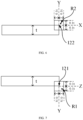
- the outer edge 121 moves toward the first reference plane X along a first outer-edge trajectory A1B1
- the inner edge 122 moves toward a side of the second reference plane Y toward the opening along a first inner-edge trajectory A2B2.
- the first reference plane X and the second reference plane Y do not move along with the door 12 and are fixed reference planes when the door 12 moves.
- the final motion direction of the inner edge 122 relative to the second reference plane Y and the final motion direction of the outer edge 121 relative to the first reference plane X will necessarily be the directions described above during the opening process of the door 12.
- the first outer-edge trajectory A1B1 has a radius of curvature greater than or equal to 5t and exceeds a side of the second reference plane Y back to the opening by a distance less than or equal to a first predetermined distance d1;
- the first inner-edge trajectory A2B2 has a radius of curvature greater than or equal to 100t and exceeds a side of the first reference plane X toward the opening by a distance less than or equal to a second predetermined distance d2, where the t is a thickness of the door.
- the radius of curvature of the motion trajectory and the distance at which the motion trajectory exceeds the reference plane are limited to ensure that the corresponding edge can move smoothly and do not exceed a predetermined range.
- a minimum value of the radius of curvature of the first outer-edge trajectory A1B1 and a minimum value of the radius of curvature of the first inner-edge trajectory A2B2 are specifically defined, i.e., when each radius of curvature is selected to be the corresponding minimum value, it can be ensured that the door 12 may not significantly compress the case 11 and that the door 12 may not excessively exceed the side of the case assembly.
- the corresponding motion trajectory is a straight line. In the case that each of the two motion trajectories is a straight line, the door 12 may be opened to reach a position at a maximum of 90 degrees relative to the case 11.
- the radius of curvature of the first outer-edge trajectory A1B1 is greater than or equal to 5t, and the radius of curvature of the first inner-edge trajectory A2B2 is greater than or equal to 100t.
- the thickness t of the door determines the extent of the door 12 moving relative to the case 11 when the door 12 is being opened. It is obvious that the thicker the door 12 is, the greater the radius of curvature of the motion trajectory is.
- the thickness of the door may be set at least 2 centimeters.
- the relevant setting of the first predetermined distance d1 determines the extent to which the outer edge 121 can exceed the side of the case assembly 100. In practice, it is permissible to allow the outer edge 121 to exceed the side of the case assembly 100 by a certain extent. For example, for an embedded use of the case assembly 100, a gap exists between the case 11 and an embedding wall, and the gap allows the outer edge 121 to exceed the side of the case assembly 100 by a certain extent.
- the relevant setting of the second predetermined distance d2 determines the extent to which the inner edges 122 can compress the case 11.
- the case 11 is arranged with a deformable door seal, and the compression to a certain extent, applied by the inner edge 121 to the case 11, may be ignored.
- the specific values of the first predetermined distance and the second predetermined distance may be determined according to the actual product design needs, for example, the first predetermined distance may be determined according to the distance between the wall in which the case assembly is embedded and the case assembly, and the second predetermined distance may be determined according to the thickness or elasticity of the door seal of the case.
- the thickness of the door is used for scalar purposes in the present embodiment to limit the first predetermined distance and the second predetermined distance to 0 to 0.15 times the thickness of the door. When 0 times is selected, the door is set to not compressing the case and not exceeding the side of the case assembly.
- 0.1 times may be specifically selected, i.e., the door is allowed to exceed the side of the case assembly by 0.1 times the thickness of the door; and the first predetermined distance may be determined to be 0mm to 4mm and the second predetermined distance to be 0mm to 2mm according to empirical values, and similarly, when 0mm is selected, the door does not exceed the side of the case assembly.
- the first predetermined distance may be 3mm and the second predetermined distance may be 1mm as an example, i.e., the allowed exceeding distances are limited.
- the inner edge 122 moves along the first inner-edge trajectory A2B2, and the outer edge 121 moves along the first outer-edge trajectory A1B1.
- the radius of curvature of the first inner-edge trajectory A2B2 and the first outer-edge trajectory A1B1, and the distance relationship between the trajectories and the second reference plane Y and the first reference plane X are characterized in a certain way, such that the door 12 is moved according to the motion trajectory, so as to attenuate or even avoid the door 12 from compressing the case 11 as well as from exceeding the side of the case assembly 100.
- an end point B2 of the first inner-edge trajectory A2B2 may be located on the first reference plane X, or the end point B2 may be located on a side of the first reference plane X back to the opening and a distance between the end point B2 and the first reference plane X may be less than or equal to 0.058t; an end point B1 of the first outer-edge trajectory A1B1 may be located on the second reference plane Y, or the end point B1 may be located on the side of the second reference plane Y toward the opening and a distance between the end point B1 and the second reference plane Y may be less than or equal to 0.135t.
- the inner edge 122 of the door 12 does not compress the case 11 and does not move excessively away from the case 11; while the outer edge 121 does not exceed the side of the case assembly 100 and does not move excessively toward the side of the second reference plane Y toward the opening.
- the above design allows the door 12 to be opened without significant displacement, and the movement of the door 12 is more stable.
- the door 12 when the outer edge 121 moves along the first outer-edge trajectory A1B1 and the inner edge 122 moves along the first inner-edge trajectory A2B2 until the door 12 is opened at 90 degrees, the door 12 may not be able to be further opened at a greater angle.
- a maximum opening angle of the door 12 is generally required to be greater than 90 degrees. Therefore, after the edge of the door 12 move along the first edge trajectory until the door 12 is opened at an angle less than 90 degrees, the edge may move along another motion trajectory such that the door 12 may be further opened at an angle more than 90 degrees.
- the first outer-edge trajectory A1B1 is shorter than the first inner-edge trajectory A2B2, and the ratio of the lengths of the first inner-edge trajectory A2B2 and the first outer-edge trajectory A1B1 is 3.5 to 4.5.
- the door 12 may move along a different trajectory after being opened at the first opening angle.
- the outer edge 121 moves along a second outer-edge trajectory B1C1 toward the first reference plane X
- the inner edge 122 moves along a second inner-edge trajectory B2C2 toward the side of the second reference plane Y toward the opening and the side of the first reference plane X back to the opening.
- the inner edge 122 starts to move toward the side of the second reference plane Y toward the opening, and a third angle between a tangent direction of the second inner-edge trajectory B2C2 of the inner edge 122 and the first reference plane X gradually increases, and a change in angle of the third angle corresponding to each unit of opening of the door 12 gradually increases.
- An end point C2 is located on the side of the first reference plane X back to the opening, which allows room for the door 12 to be opened at a greater angle.
- a tangent direction of the second outer-edge trajectory B1C1 is set perpendicular to the first reference plane X, or is set inclined relative to the first reference plane X at a fourth angle of between 70 degrees and 110 degrees.
- the door 12 may not compress the case 11 or excessively exceed the side of the case 11.
- the fourth angle may remain unchanged, i.e., the second outer-edge trajectory B1C1 is in a straight line; alternatively, the second outer-edge trajectory B1C1 varies monotonically in a straight-line form, and the second outer-edge trajectory B1C1 is in the form of an arc. In this way, the outer edge 121 may move smoothly along the straight-line or the arc-shaped second outer-edge trajectory B1C1.
- a difference between a maximum value and a minimum value of the fourth angle is greater than or equal to 10 degrees, i.e., the second outer-edge trajectory B1C1 is overall gentle, further ensuring smooth movement of the outer edge 121 along the second outer-edge trajectory B1C1.
- the third angle may gradually increase, i.e., the second inner-edge trajectory B2C2 is in the form of an arc, and the inner edge 122 moves smoothly along the arc-shaped second inner-edge trajectory B2C2.
- a difference between a maximum value and a minimum value of the third angle is greater than or equal to 35 degrees, i.e., the second inner-edge trajectory B2C2 is overall gentle, further ensuring smooth movement of the inner edge 122 along the second inner-edge trajectory B2C2.
- the inner edge 122 starts to move toward the side of the second reference plane Y toward the opening, and the motion trajectory of the inner edge 122 may be in the form of an arc.
- the radius of curvature of the second inner-edge trajectory B2C2 may gradually decrease.
- the end point C2 may be located on the side of the first reference plane X back to the opening, and the distance between the end point C2 and the first reference plane may be greater than or equal to 0.3t.
- the second outer-edge trajectory B1C1 has a radius of curvature greater than or equal to 5t, and a distance of the second outer-edge trajectory B1C1 exceeding the side of the second reference plane Y back to the opening is less than or equal to the first predetermined distance d1.
- the door 12 may not compress the case 11 or excessively exceed the side of the case assembly.
- the second outer-edge trajectory B1C1 is a continuation of the first outer-edge trajectory A1B1, while the second inner-edge trajectory B2C2 is an arc with a gradually decreasing radius of curvature set up in order to facilitate the subsequent opening at a greater angle and in orderto make the opening of the door smoother.
- the present disclosure further proposes the following scheme: during the process of the door 12 moving from the opened state at the first opening angle to the opened state at the second opening angle relative to the case 11, the inner edge 122 moves along the second inner-edge trajectory B2C2 toward the side of the second reference plane Y toward the opening and the side of the first reference plane X back to the opening, and the radius of curvature of the second inner-edge trajectory B2C2 gradually decreases; the outer edge 121 moves along the second outer-edge trajectory B1C1 toward the first reference plane X, the radius of curvature of the second outer-edge trajectory is greater than or equal to 5t, and the distance of the second outer-edge trajectory B1C1 exceeding the side of the second reference plane Y back to the opening is less than or equal to the first predetermined distance.
- the first opening angle herein may be a closing angle and the second opening angle may be any angle.
- the second inner-edge trajectory may be A2C2, and the second outer-edge trajectory may be A1C1.
- the inner edge 122 moves away from the opening of the case along the second inner-edge trajectory, avoiding the door from compressing the case; the radius of curvature of the second outer-edge trajectory of the outer edge 21 is greater than or equal to 5t, and the distance of the second outer-edge trajectory exceeding the side of the second reference plane Y back to the opening is less than or equal to the first predetermined distance.
- the above design may avoid the door from exceeding the side of the case assembly.
- a difference between the first opening angle and the second opening angle may be limited to 25 degrees-60 degrees.
- the door 12 may continue to be opened from the second opening angle to a third opening angle relative to the case 11.
- the inner edge 122 moves along a third inner-edge trajectory C2D2 toward the side of the first reference plane X back to the opening
- the outer edge 121 moves along a third outer-edge trajectory C1D1 toward the side of the second reference plane Y toward the opening.
- the motion trajectories correspond to a greater opening angle of the door 12.
- the third outer-edge trajectory C1D1 and the third inner-edge trajectory C2D2 may specifically be concentrically disposed arcs, the third inner-edge trajectory C2D2 having a radius of curvature of 0.55t-0.67t, and the third outer-edge trajectory C1D1 having a radius of curvature of 0.45t-0.55t.
- the edges of the door 12 move along the first inner-edge trajectory A2B2 and the first outer-edge trajectory A1B1, in order to realize a greater opening angle of the door, the edges may move directly along the third outer-edge trajectory C1D1 and the third inner-edge trajectory C2D2, respectively, thereby solving the problem of compressing the case 11 and exceeding the side of the case assembly.
- the door 12 may be prone to shaking during the rotation process of the door 12 under the action of the hinge assembly 13.
- the second trajectories are added between the first trajectories the third trajectories, so as to make the motion process of the door 12 more stable and smoother.
- the ratio of the radius of curvature of the third inner-edge trajectory C2D2 to the radius of curvature of the third outer-edge trajectory C1D1 may be 1.22, which is able to prevent structures on the hinge assembly 13 corresponding to the third trajectories from interfering with each other.
- each set of the three-section trajectory is designed such that the first trajectory corresponds to the first opening angle of 25 degrees to 31 degrees, the second trajectory corresponds to the second opening angle of 57 degrees to 60 degrees, and the third trajectory corresponds to the third opening angle of 122 degrees to 132 degrees.
- the length of the first inner-edge trajectory A2B2 is 0.465t, and the length of the first outer-edge trajectory A1B1 is 0.115t.
- the length of the second outer-edge trajectory B1C1 is 0.2285t, and the second inner-edge trajectory B2C2 is set such that a motion distance of the outer edge 121 on the second outer-edge trajectory B1C1 and a rotation angle of the door 12 relative to the case 11 satisfy the following equation.
- ⁇ 1 t 1 t ⁇
- ⁇ 1 the rotation angle
- ⁇ is a preset angle of 100 degrees-113 degrees
- t1 is the motion distance.
- a circle center of the third inner-edge trajectory C2D2 is located in the door 12 and the radius of curvature is 0.61t.
- a circle center of the third outer-edge trajectory C1D1 is located in the door 12 and the radius of curvature is 0.5t.
- a perpendicular distance from the circle center to the first reference plane X is 0.6t, and a perpendicular distance from the circle center to the second reference plane Y is 0.5t.
- a reference point may be selected for trajectory design, so as to reserve a tolerance for the edge on the door 12, ensuring that the door 12 is avoided from compressing the case 11 and from exceeding the side of the case assembly 100.
- FIG. 5 is a schematic view of a motion trajectory of reference points in the case assembly shown in FIG. 1
- FIG. 6 is a schematic view of a selection range of an inner reference point in the case assembly shown in FIG. 1
- FIG. 7 is a schematic view of a selection range of an outer reference point in the case assembly shown in FIG. 1 .
- an outer reference point R1 and an inner reference point R2 are defined.
- the outer reference point R1 is located adjacent to the outer edge 121
- the inner reference point R2 is located adjacent to the inner edge 122.
- a third reference plane Z is hereby defined, which is parallel to the first reference plane X and passes through the outer edge 121 when in the closed state.
- a perpendicular distance from the inner reference point R2 to the second reference plane Y and a perpendicular distance from the inner reference point R2 to the first reference plane X are each less than or equal to 0.1t.
- the inner reference point R2 is selected in a rectangular region centered on the inner edge 122 with a side length of 0.2t.
- a perpendicular distance from the outer reference point R1 to the second reference plane Y and a perpendicular distance from the outer reference point R1 to the third reference plane Z are each less than or equal to 0.1t.
- the outer reference point R1 is selected in a rectangular region centered on the outer edge 121 with a side length of 0.2t.
- the outer reference point R1 may be selected on the outer edge 121, and the inner reference point R2 may be selected on the inner edge 122.
- the motion trajectory design ideas of the inner reference point R2 and the outer reference point R1 are also based on the above trajectory design ideas of the inner edge 122 and the outer edge 121.
- the inner reference point R2 moves along a first inner-reference-point trajectory E2F2 toward the side of the second reference plane Y toward the opening
- the outer reference point R1 moves along a first outer-reference-point trajectory E1F1 toward the first reference plane X.
- Characteristics of the first inner-reference-point trajectory E2F2 may be all similar to those of the first inner-edge trajectory A2B2, and characteristics of the first outer-reference-point trajectory E1F1 may be all similar to those of the first outer-edge trajectory A1B1, which will not be further described herein.
- the first inner-reference-point trajectory E2F2 may be a straight line and the first outer-reference-point trajectory E1F1 may be a straight line. Based on a selected position of the inner reference point R2, the first inner-reference-point trajectory E2F2 may be parallel to the first reference plane X or along the first reference plane X; and based on a selected position of the outer reference point R1, the first outer-reference-point trajectory may be parallel to the second reference plane Y or along the second reference plane Y.
- first inner-reference-point trajectory E2F2 may be longer than the first outer-reference-point trajectory E1F1, and the ratio of the lengths of the first inner-reference-point trajectory E2F2 and the first outer-reference-point trajectory E1F1 is 3.5 to 4.5.
- both the outer reference point R1 and the inner reference point R2 may each have a second trajectory and a third trajectory.
- a second inner-reference-point trajectory F2G2 may have characteristics similar to the second inner-edge trajectory B2C2, and a second outer-reference-point trajectory F1G1 may have characteristics similar to the second outer-edge trajectory B1C1;
- a third inner-reference-point trajectory G2H2 may have characteristics similar to the third inner-edge trajectory C2D2, and a third outer-reference-point trajectory G1H1 may have characteristics similar to the third outer-edge trajectory C1D1.
- the inner reference point R2 moves along the second inner-reference-point trajectory F2G2 toward the side of the second reference plane Y toward the opening and the side of the first reference plane X back to the opening, and the outer reference point R1 moves along the second outer-reference-point trajectory F1G1 toward the first reference plane X.
- the second outer-reference-point trajectory F1G1 may be a straight line, and may be along the second reference plane Y or parallel to the second reference plane Y.
- the present disclosure also mitigates the problems of the door compressing the case and exceeding the side of the case assembly by limiting a tangential direction of the motion trajectory of the edge on the door.
- the relative motion of the door and the case can be converted into the motion of the tangent direction of the motion trajectory.
- the tangent direction of the motion trajectory of the edge By designing the tangent direction of the motion trajectory of the edge, the relative motion relationship between the door and the case may be limited, such that the door may not excessively compress the doorway and not excessively exceed the side of the case assembly.
- a motion trajectory of tangent direction of the motion trajectory of the edge a motion trajectory of a fixed point on the case or the door may be determined, and the hinge assembly may thus be designed by inverse deduction according to the motion trajectory of the fixed point. That is, the hinge assemblies that can realize the motion trajectory of the edge in the present disclosure are within the scope of the present disclosure.
- FIG. 3 is a schematic view of a motion trajectory of an edge in the case assembly shown in FIG. 1
- FIG. 4 is a schematic view illustrating an opening angle of a door relative to a case and a motion trajectory of an edge in the case assembly shown in FIG. 1 .
- the tangent direction of the first outer-edge trajectory A1B1 is set perpendicular to the first reference plane X, or the tangent direction of the first outer-edge trajectory A1B1 may be set inclined relative to the first reference plane X at a second angle progressively approaching 90 degrees; the tangent direction of the first inner-edge trajectory A2B2 is set along the first reference plane X, or the tangent direction of the first inner-edge trajectory A2B2 is set inclined relative to the first reference plane X at a first angle of less than or equal to 10 degrees.
- the tangent direction of the motion trajectory is limited, and the ratio of the lengths of the first inner-edge trajectory A2B2 and the first outer-edge trajectory ALBA is also limited, so as to ensure that the edges are able to move smoothly and do not exceed a predetermined range.
- the tangent direction of the first outer-edge trajectory A1B1 is set at the second angle gradually approaching 90 degrees inclined relative to the first reference plane X, ensuring that the door 12 may not significantly compress the case 11.
- the tangent direction of the first inner-edge trajectory A2B2 is set at the first angle of a maximum value of 10 degrees relative to the first reference plane X, ensuring that the door 12 may not excessively exceed the side of the case 11.
- the two trajectories are straight lines.
- the first opening angle may be up to 90 degrees, in which case the first inner-edge trajectory A2B2 is longer than the first outer-edge trajectory A1B1, and the ratio of the lengths of the first inner-edge trajectory A2B2 and the first outer-edge trajectory A1B1 is 3.5-4.5.
- the relevant setting of the tangent direction of the first inner-edge trajectory A2B2 determines the extent to which the inner edge 122 can compress the case 11. In practice, it is permissible to allow the inner edge 122 to compress the case 11 to a certain extent. For example, the case 11 is arranged with a deformable door seal, and the compress to a certain extent, applied by the inner edge 122 to the case 11, may be ignored.
- the relevant setting of the tangent direction of the first outer-edge trajectory A1B1 determines the extent to which the outer edge 121 can exceed the side of the case 11.
- a gap exists between the case 11 and an embedding wall, and the gap allows the outer edge 121 to exceed the side of the case 11 by a certain extent.
- the first angle may remain unchanged, i.e., the first inner-edge trajectory A2B2 is in a straight line; alternatively, the first angle varies monotonically in a straight-line form, and the first inner-edge trajectory A2B2 is in the form of an arc. In this way, the inner edge 122 may move smoothly along the straight-line or the arc-shaped first inner-edge trajectory A2B2.
- a difference between a maximum value and a minimum value of the first angle is less than 5 degrees, i.e., the first inner-edge trajectory A2B2 is overall gentle, further ensuring smooth movement of the inner edge 122 along the first inner-edge trajectory A2B2.
- the second angle may remain unchanged, i.e., the first outer-edge trajectory A1B1 is in a straight line; alternatively, the second angle gradually approaches 90 degrees, i.e., the first outer-edge trajectory A1B1 is in the form of an arc. In this way, the outer edge 121 may move smoothly along the straight-line or the arc-shaped first outer-edge trajectory A1B1.
- the inner edge 122 starts to move toward the side of the second reference plane Y toward the opening, and the motion trajectory of the inner edge 122.
- the radius of curvature of the second inner-edge trajectory B2C2 may gradually decrease.
- the end point C2 may be located on the side of the first reference plane X back to the opening, and the distance between the end point C2 and the first reference plane X may be greater than or equal to 0.3t. The above design allows room for the door 12 to be opened at a greater angle.
- the second outer-edge trajectory B1C1 has a radius of curvature greater than or equal to 5t, and a distance of the second outer-edge trajectory B1C1 exceeding the side of the second reference plane Y back to the opening is less than or equal to the first predetermined distance d1.
- the door 12 may not compress the case 11 or excessively exceed the side of the case assembly.
- the door 12 may continue to be opened from the second opening angle to the third opening angle relative to the case 11.
- the inner edge 122 moves along the third inner-edge trajectory C2D2 toward the side of the first reference plane X back to the opening
- the outer edge 121 moves along the third outer-edge trajectory C1D1 toward the side of the second reference plane Y toward the opening.
- the motion trajectory corresponds to a greater opening angle of the door 12.
- the third outer-edge trajectory C1D1 and the third inner-edge trajectory C2D2 may specifically be concentrically disposed arcs, the third inner-edge trajectory C2D2 having a radius of curvature of 0.55t-0.67t, and the third outer-edge trajectory C1D1 having a radius of curvature of 0.45t-0.55t.
- the edges of the door 12 move along the first inner-edge trajectory A2B2 and the first outer-edge trajectory A1B1, in order to realize a greater opening angle of the door, the edges may move directly along the third outer-edge trajectory C1D1 and the third inner-edge trajectory C2D2, respectively, thereby solving the problem of compressing the case 11 and exceeding the side of the case assembly.
- the door 12 may be prone to shaking during the rotation process of the door 12 under the action of the hinge assembly 13.
- the second trajectories are added between the first trajectories and the third trajectories, so as to make the motion process of the door 12 more stable and smoother.
- the ratio of the radius of curvature of the third inner-edge trajectory C2D2 to the radius of curvature of the third outer-edge trajectory C1D1 may be 1.22, which is able to prevent structures on the hinge assembly 13 corresponding to the third trajectories from interfering with each other.
- each set of the three-section trajectory is designed such that the first trajectory corresponds to the first opening angle of 25 degrees to 31 degrees, the second trajectory corresponds to the second opening angle of 57 degrees to 60 degrees, and the third trajectory corresponds to the third opening angle of 122 degrees to 132 degrees.
- the length of the first inner-edge trajectory A2B2 is 0.465t, and the length of the first outer-edge trajectory A1B1 is 0.115t.
- the length of the second outer-edge trajectory B1C1 is 0.2285t, and the second inner-edge trajectory B2C2 is set such that a motion distance of the outer edge 121 on the second outer-edge trajectory B1C1 and a rotation angle of the door 12 relative to the case 11 satisfy the following equation.
- ⁇ 1 t 1 t ⁇
- ⁇ 1 the rotation angle
- ⁇ is a preset angle of 100 degrees-113 degrees
- t1 is the motion distance.
- a circle center of the third inner-edge trajectory C2D2 is located in the door 12 and the radius of curvature is 0.61t.
- a circle center of the third outer-edge trajectory C1D1 is located in the door 12 and the radius of curvature is 0.5t.
- a perpendicular distance from the circle center to the first reference plane X is 0.6t, and a perpendicular distance from the circle center to the second reference plane Y is 0.5t.
- a reference point may be selected for trajectory design, so as to reserve a tolerance for the edge on the door 12, ensuring that the door 12 is avoided from compressing the case 11 and from exceeding the side of the case assembly 100.
- FIG. 5 is a schematic view of a motion trajectory of reference points in the case assembly shown in FIG. 1
- FIG. 6 is a schematic view of a selection range of an inner reference point in the case assembly shown in FIG. 1
- FIG. 7 is a schematic view of a selection range of an outer reference point in the case assembly shown in FIG. 1
- FIG. 8 is a schematic view of an angle of a tangent direction of a trajectory of an inner reference point in the case assembly shown in FIG. 1
- FIG. 9 is a schematic view of an angle of a tangent direction of a trajectory of an outer reference point in the case assembly shown in FIG. 1 .
- an inner reference point R2 and an outer reference point R1 are defined.
- the outer reference point R1 is located adjacent to the outer edge 121, and the inner reference point R2 is located adjacent to the inner edge 122.
- a third reference plane Z is hereby defined, which is parallel to the first reference plane X and passes through the outer edge 121 when in the closed state.
- a perpendicular distance from the inner reference point R2 to the second reference plane Y and a perpendicular distance from the inner reference point R2 to the first reference plane X are each less than or equal to 0.1t.
- the inner reference point R2 is selected in a rectangular region centered on the inner edge 122 with a side length of 0.2t.
- a perpendicular distance from the outer reference point R1 to the second reference plane Y and a perpendicular distance from the outer reference point R1 to the third reference plane Z are each less than or equal to 0.1t.
- the outer reference point R1 is selected in a rectangular region centered on the outer edge 121 with a side length of 0.2t.
- the outer reference point R1 may be selected on the outer edge 121, and the inner reference point R2 may be selected on the inner edge 122.
- the motion trajectory design ideas of the inner reference point R2 and the outer reference point R1 are also based on the above trajectory design ideas of the inner edge 122 and the outer edge 121.
- the inner reference point R2 moves along the first inner-reference-point trajectory E2F2 toward the side of the second reference plane Y toward the opening
- the outer reference point R1 moves along the first outer-reference-point trajectory E1F1 toward the first reference plane X.
- Characteristics of the first inner-reference-point trajectory E2F2 may be all similar to those of the first inner-edge trajectory A2B2, and characteristics of the first outer-reference-point trajectory E1F1 may be all similar to those of the first outer-edge trajectory A1B1.
- the tangent directions of the first inner-reference-point trajectory E2F2 and the second outer-reference-point trajectory E1F1 are specified below.
- a coordinate system is established with any point on the inner edge 122 of the door 12 when in the closed state as an origin, with a straight line passing through the origin and located on the first reference plane X and perpendicular to the second reference plane Y as an x-axis, and with a straight line passing through the origin and located on the second reference plane Y and perpendicular to the first reference plane X as a y-axis.
- the inner reference points R2 are taken as (-0.1t,0.1t) (0,0.1t), (0.1t,0.1t), (-0.1t,0), (0,0), (0.1t,0), (-0.1t,-0.1t), (0,-0.1t), (0,-0.1t), (0.1t,0.1t), respectively, and are ordered from left to right on FIG. 8 beginning from the first row corresponding to the first inner-reference-point trajectory E2F2.
- the tangent direction of the first inner-reference-point trajectory E2F2 is set along the first reference plane X, or is set inclined relative to the first reference plane X at a fifth angle of less than or equal to 10 degrees.
- the fifth angle may remain unchanged or monotonically varies in a straight-line form, with a difference between a maximum value and a minimum value of the fifth angle being less than 5 degrees.
- a coordinate system is established with any point on the outer edge 121 of the door 12 when in the closed state as an origin, with a line passing through the origin and located on the third reference plane Z and perpendicular to the second reference plane Y as an x-axis, and with a line passing through the origin and located on the second reference plane Y and perpendicular to the third reference plane Z as a y-axis.
- the outer reference points R1 are taken as (-0.1t,0.1t), (0,0.1t), (0.1t,0.1t), (-0.1t,0), (0,0), (0.1t,0), (-0.1t,-0.1t), (0,-0.1t), (0,-0.1t), (0.1t,0.1t), respectively, and are ordered from left to right on FIG. 9 beginning from the first row corresponding to the first outer-reference-point trajectory E1F1.
- the tangent direction of the first outer-reference-point trajectory E1F1 is set perpendicular to the first reference plane X, or is set inclined relative to the first reference plane X at a sixth angle gradually approaching 90 degrees.
- the ratio of the lengths of the first inner-reference-point trajectory E2F2 and the first outer-reference-point trajectory E1F1 is 3.5 to 4.5.
- the first inner-reference-point trajectory E2F2 may be a straight line and the first outer-reference-point trajectory E1F1 may be a straight line. Based on a selected position of the inner reference point R2, the first inner-reference-point trajectory E2F2 may be parallel to the first reference plane X or along the first reference plane X; and based on a selected position of the outer reference point R1, the first outer-reference-point trajectory may be parallel to the second reference plane Y or along the second reference plane Y.
- the tangent direction of the first outer-reference-point trajectory E1F1 is perpendicular to the first reference plane X
- the tangent direction of the first inner-reference-point trajectory E2F2 is set along the first reference plane X.
- both the outer reference point R1 and the inner reference point R2 may each have a second trajectory and a third trajectory.
- a second inner-reference-point trajectory F2G2 may have characteristics similar to the second inner-edge trajectory B2C2, and a second outer-reference-point trajectory F1G1 may have characteristics similar to the second outer-edge trajectory B1C1;
- a third inner-reference-point trajectory G2H2 may have characteristics similar to the third inner-edge trajectory C2D2, and a third outer-reference-point trajectory G1H1 may have characteristics similar to the third outer-edge trajectory C1D1.
- a coordinate system is established with any point on the inner edge 122 of the door 12 when in the closed state as an origin, with a straight line passing through the origin and located on the first reference plane X and perpendicular to the second reference plane Y as an x-axis, and with a straight line passing through the origin and located on the second reference plane Y and perpendicular to the first reference plane X as a y-axis.
- the inner reference points R2 are taken as (-0.1t,0.1t), (0,0.1t), (0.1t,0.1t), (-0.1t,0), (0,0), (0.1t,0), (-0.1t,-0.1t), (0,-0.1t), (0,-0.1t), (0.1t,0.1t), respectively, and are ordered from left to right on FIG. 8 beginning from the first row corresponding to the second inner-reference-point trajectory F2G2.
- a seventh angle between the tangent direction of the second inner-reference-point trajectory F2G2 and the first reference plane X gradually increases, and a change in angle of the seventh angle corresponding to each unit of opening of the door 12 gradually increases.
- a difference between a maximum value and a minimum value of the seventh angle is greater than or equal to 35 degrees.
- a coordinate system is established with any point on the outer edge 121 of the door 12 when in the closed state as an origin, with a line passing through the origin and located on the third reference plane Z and perpendicular to the second reference plane Y as an x-axis, and with a line passing through the origin and located on the second reference plane Y and perpendicular to the third reference plane Z as a y-axis.
- the outer reference points R1 are taken as (-0.1 t,0.1t), (0,0.1t), (0.1t,0.1t), (-0.1t,0), (0,0), (0.1t,0), (-0.1t,-0.1t), (0,-0.1t), (0,-0.1t), (0.1t,0.1t), respectively, and are ordered from left to right on FIG. 9 beginning from the first row corresponding to the second outer-reference-point trajectory F1G1.
- the tangent direction of the second outer-reference-point trajectory F1G1 is set perpendicular to the first reference plane X, or is set inclined relative to the first reference plane X at an eighth angle between 70 degrees and 110 degrees.
- the eighth angle may remain unchanged or monotonically varies in a straight-line form, with a difference between a maximum value and a minimum value of the eighth angle being less than or equal to 10 degrees.
- the inner reference point R2 moves along the second inner-reference-point trajectory F2G2 toward the side of the second reference plane Y toward the opening and the side of the first reference plane X back to the opening, and the outer reference point R1 moves along the second outer-reference-point trajectory F1G1 toward the first reference plane X.
- the second outer-reference-point trajectory F1G1 may be a straight line, and may be along the second reference plane Y or parallel to the second reference plane Y.
- the present disclosure also mitigates the problem of the door compressing the case and exceeding the side of the case assembly by limiting a motion trajectory of a motion instantaneous center of the door.
- the relative motion of the door and the case can be converted into the motion of the instantaneous center of the door.
- the motion trajectory of the instantaneous center By designing the motion trajectory of the instantaneous center, the relative motion relationship between the door and the case may be limited, such that the door may not excessively compress the doorway and not excessively exceed the side of the case assembly.
- a motion trajectory of a fixed point on the case or the door may be determined according to the motion trajectory of the instantaneous center, and the hinge assembly may thus be designed by inverse deduction according to the motion trajectory of the fixed point. That is, the hinge assemblies that can realize the motion trajectory of the motion instantaneous center and the motion trajectory of the edge in the present disclosure is within the scope of the present disclosure.
- FIG. 10 is a schematic view of a motion-instantaneous-center trajectory of a motion instantaneous center of a door in the case assembly shown in FIG. 1 according to a third implementation of the present disclosure.
- the motion trajectory of the motion instantaneous center of the door 12 is limited. Specifically, the motion instantaneous center starts from the outer edge 121 along a first motion-instantaneous-center trajectory A3B3 toward the first reference plane X and simultaneously toward the side of the second reference plane Y toward the opening, thereby ensuring that the door 12 may not excessively compress the case 11 and not excessively exceed the side of the case 11.
- the relevant setting of the motion trajectory of the motion instantaneous center of the door 12 determine the extent to which the inner edge 122 can compress the case 11 and the extent to which the outer edge 121 can exceed the side of the case assembly.
- the case 11 is arranged with a deformable door seal, and the compress to a certain extent, applied by the inner edge 122 to the case 11, may be ignored.
- a gap exists between the case 11 and an embedding wall, and the gap allows the outer edge 121 to exceed the side of the case 11 by a certain extent.
- any cross-sectional figure S (or an extension thereof) on the rigid body parallel to a fixed plane is not zero at any instant, there must be a point P', called an instantaneous center of velocity, at which the velocity is zero.
- the sectional figure (or an extension thereof) appears to be rotating only about a point P on the fixed plane coinciding with P', the point P being called an instantaneous center of rotation.
- the motion instantaneous center in the present embodiment may be the instantaneous center of rotation or the instantaneous center of velocity of the door 12.
- an angle between a perpendicular line connecting the motion instantaneous center and the inner edge 122 and the first reference plane X is between 85 and 95 degrees. Within this range, it may be ensured that the first inner-edge trajectory A2B2 of the inner edge 122 moves toward the side of the second reference plane Y toward the opening and does not excessively compress the case 11.
- a maximum value and a minimum value of the angle between the perpendicular line connecting the motion instantaneous center and the inner edge 122 and the first reference plane X during the opening of the door are specifically defined as 95 degrees and 85 degrees, respectively, which may ensure that the door 12 may not excessively compress the case 11
- an angle between a perpendicular line connecting the motion instantaneous center and the outer edge 121 and the second reference plane Y is between 85 and 95 degrees. Within this range, it may be ensured that the first outer-edge trajectory A1B1 of the outer edge 122 moves toward the first reference plane X and does not excessively exceed the side of the case 11.
- a maximum value and a minimum value of the angle between the perpendicular line connecting the motion instantaneous center and the outer edge 121 and the second reference plane Y during the opening of the door are specifically defined as95 degrees and 85 degrees, respectively, which may ensure that the door 12 may not excessively exceed the side of the case 11.
- the perpendicular line connecting the motion instantaneous center and the inner edge 122 is perpendicular to the first reference plane X, and during the opening process of the door 12 to the first angle, the first inner-edge trajectory A2B2 of the inner edge 122 is in a straight line and is parallel to the first reference plane X.
- the perpendicular line connecting the motion instantaneous center and the outer edge 121 is perpendicular to the second reference plane Y, and during the opening process of the door 12 to the first angle, the first outer-edge trajectory A1B1 of the outer edge 121 is in a straight line and parallel to the second reference plane Y.
- the present embodiment ensures that the edges are able to move smoothly by limiting the positional relationships of the motion instantaneous center with the inner edge 122 and the outer edge 121, thereby ensuring that the door 12 does not compress the case 11 and not exceed the side of the case 11.
- the first motion-instantaneous-center trajectory A3B3 of the motion instantaneous center of the door 12 is in the form of an arc
- a circle center of the arc is located at the midpoint of a perpendicular line connecting the inner edge 122 and the outer edge 121
- the diameter of the arc is a perpendicular distance between the inner edge 122 and the outer edge 121.
- the first inner-edge trajectory A2B2 of the inner edge 122 is in a straight line and parallel to the first reference plane X
- the first outer-edge trajectory A1B1 of the outer edge 121 is straight and parallel to the second reference plane Y.
- the present embodiment ensures that the edges are able to move smoothly by limiting the first motion-instantaneous-center trajectory of the motion instant center, thereby ensuring that the door 12 does not compress the case 11 and not exceed the side of the case 11.
- an angle between a line connecting the motion instantaneous center and the circle center and a line connecting the circle center and a start point of the first motion-instantaneous-center trajectory A3B3 is equal to an actual opening angle of the door 12 relative to the case 11.
- the movement of the motion instantaneous center varies regularly with the first opening angle of the door 12, and the process of the door 12 opening to the first opening angle is overall smooth, avoiding the situation of sliding jam and ensuring that the door 12 does not compress the case 11 and not exceed the side of the case 11.
- the first opening angle is between 25 degrees and 31 degrees; for example, the first opening angle may be 25 degrees, 28 degrees, 30 degrees, or 31 degrees. Within the first opening angle, it may be ensured that the door 12 does not compress the case 11 and not exceed the side of the case 11.
- the motion instantaneous center of the door 12 starts from the outer edge 121 and moves along the first motion-instantaneous-center trajectory A3B3 toward the first reference plane X, and simultaneously toward the side of the second reference plane Y toward the opening.
- the first motion-instantaneous-center trajectory A3B3 has certain characteristics, and the door 12 moves according to the first motion-instantaneous-center trajectory A3B3, so as to attenuate or even avoid the door 12 from compressing the case 11 and from exceeding the side of the case 11.
- the inner edge 122 of the door 12 does not compress the case 11 and does not move excessively away from the case 11, while the outer edge 121 does not exceed the side of the case assembly 100 and does not move excessively toward the side of the second reference plane Y toward the opening.
- the above design allows the door 12 to be opened without significant displacement, and the movement of the door 12 is more stable.
- the door 12 when the motion instantaneous center of the door 12 moves along the first motion-instantaneous-center trajectory until the door 12 is opened at 90 degrees, the door 12 may not be able to be further opened at a greater angle, and a maximum opening angle of the door 12 is generally required to be greater than 90 degrees. Therefore, after the motion instantaneous center of the door 12 moves along the first inner motion-instantaneous-center trajectory until the door 12 is opened at an angle less than 90 degrees, the motion instantaneous center may move along another motion trajectory such that the door 12 may be further opened at an angle more than 90 degrees.
- the door 12 may move along a different trajectory after being opened at the first opening angle.
- the motion instantaneous center moves along a second motion-instantaneous-center trajectory B3C3 toward the first reference plane X.
- An angle between a tangent direction of the second motion-instantaneous-center trajectory B3C3 and the first reference plane X is between 85 degrees and 95 degrees.
- the door 12 may not compress the case 11 or excessively exceed the side of the case 11, allowing room for the door 12 to be opened at a greater angle.
- the motion instantaneous center moves along the second motion-instantaneous-center trajectory B3C3 toward the first reference plane X, and the tangent direction of the second motion-instantaneous-center trajectory B3C3 is at an angle between 85 degrees and 95 degrees relative to the first reference plane X.
- the motion instantaneous center is always located on a side of the outer edge 121 back to the second reference plane Y, it may be ensured that the outer edge 122 does not excessively exceed the side of the case 11.
- the instantaneous motion center is always located on the side of the inner edge 121 back to the first reference plane X, it may be ensured that the first inner-edge trajectory A2B2 of the inner edge 122 moves toward the side of the second reference plane Y toward the opening and does not excessively compress the case 11.
- the second motion-instantaneous-center trajectory B3C3 is in a straight line and is set perpendicular to the first reference plane X.
- the second outer-edge trajectory B1C1 of the outer edge 121 is a straight line
- the second outer-edge trajectory B1C1 is set parallel to the second reference plane Y, ensuring that the outer edge 121 does not excessively exceed the side of the case 11; the inner edge 122 moves away from the first reference plane X, ensuring that the door 12 does not excessively compress the case 11.
- the end point C2 of the second inner-edge trajectory B2C2 is located on the side of the first reference plane X back to the opening, allowing room for the door 12 to be opened at a greater angle.
- the second motion-instantaneous-center trajectory B3C3 of the motion instantaneous center varies regularly with the second opening angle of the door 12, and the process of the door 12 moving from the opened state at the first opening angle to the opened state at the second opening angle is overall smooth, avoiding the situation of sliding jam.
- the angle between the perpendicular line connecting the motion instantaneous center and the outer edge 121 and the second reference plane Y is between 85 degrees and 95 degrees. Within this range, it may be ensured that the second outer-edge trajectory B1C1 of the outer edge 122 moves toward the first reference plane X and does not excessively exceed the side of the case 11.
- a maximum value and a minimum value of the angle between the perpendicular line connecting the motion instantaneous center and the outer edge 121 and the second reference plane Y during the opening of the door are specifically defined as95 degrees and 85 degrees, respectively, which may ensure that the door 12 may not excessively exceed the side of the case 11.
- the second outer-edge trajectory B1C1 of the outer edge 121 is a straight line and perpendicular to the first reference plane X during the process of the motion instantaneous center of the door 12 moving along the second motion-instantaneous-center trajectory B3C3, ensuring that the door 12 may not excessively exceed the side of the case 11.
- the perpendicular distance from the inner edge 122 to the motion instantaneous center gradually decreases, such that the radius of curvature of the second inner-edge trajectory B2C2 of the inner edge 122 gradually decreases, and the end point C2 is located on the side of the first reference plane X back to the opening. Therefore, there is room for the door 12 to be opened to a greater angle, and it may be ensured that the door 12 may not compress the case.
- the door 12 may not compress the case 11 or excessively exceed the side of the case 11.
- the second opening angle is between 57 degrees and 60 degrees
- the first opening angle may be 57 degrees, 58 degrees, 59 degrees, or 60 degrees, and the like. Within the second opening angle, it may be ensured that the door 12 may not compress the case 11 or exceed the side of the case 11.
- the door 12 may continue to be opened from the second opening angle to a third opening angle relative to the case 11.
- the motion instantaneous center may remain unchanged, and the door 12 is rotated around the motion instantaneous center as a whole.
- the motion trajectory corresponds to a greater opening angle of the door 12.
- the motion instantaneous center remains unchanged at the end point of the second motion-instantaneous-center, and the third inner-edge trajectory C2D2 of the inner edge 122 and the third outer-edge trajectory C1D1 of the outer edge 121 are specified to be concentrically disposed arcs.
- the door 12 may not compress the case 11 or excessively exceed the side of the case 11.
- the motion instantaneous center may move directly along a third motion-instantaneous-center trajectory C3D3 with the end point of the first motion-instantaneous-center trajectory A3B3 as a start, thereby solving the problem of compressing the case 11 and exceeding the side of the case 11.
- the door 12 may be prone to shaking during the rotation process of the door 12 under the action of the hinge assembly 13.
- the second motion-instantaneous-center trajectory B3C3 is added between the first motion-instantaneous-center trajectory A3B3 and the third motion-instantaneous-center trajectory, so as to make the motion process of the door 12 more stable and smoother.
- FIG. 11 is a structural schematic view of a case assembly according to a fourth implementation of the present disclosure
- FIG. 12 is a schematic view of a hinge shaft structure of a hinge assembly in the case assembly shown in FIG. 11
- FIG. 14 is a schematic view of a hinge slot structure of a hinge assembly in the case assembly shown in FIG. 11 .
- the fourth implementation specifies the structure of the hinge assembly as compared to the first implementation shown in FIG. 1 , and therefore the reference numerals continue to follow those in the first implementation.
- the design of the hinge assembly 13 in the case assembly 100 of the present embodiment is to convert the motion trajectories of the edges of the door 12 into the motion trajectories of two fixed points on the door 12 or the case 11, and design the corresponding mechanical structure based on the motion trajectories of the two fixed points.
- the hinge assembly 13 comprises a first guiding mechanism 135 and a second guiding mechanism 136 to realize the motion trajectories of the two fixed points, i.e., the two guiding mechanisms may cooperate to make the edges of the door 12 move along the predetermined trajectories.
- the guiding mechanism is a slot-shaft cooperation structure.
- the guiding mechanisms designed based on the motion trajectories may be linking rod structures, slot-shaft + linking rod structure, etc.
- the hinge assembly 13 in the present embodiment is a dual-shaft and dual-slot design, and the two slots are defined on the door 12 and the two shafts are arranged on the case 11.
- the two slots may be defined on the case 11 and the two shafts are arranged on the door 12; or the door 12 is arranged with one shaft and one slot, and the case 11 is arranged with the other shaft and the other slot; or, as mentioned above, the slot-shaft structures on the door 12 and the case 11 may be converted into connecting rod structures, or shaft + track sliding structures, etc.
- the hinge assembly 13 of the present embodiment comprises a first hinge shaft 131 and a second hinge shaft 132 arranged on the case 11, and a first hinge slot 133 and a second hinge slot 134 defined on the door 12.
- the first hinge shaft 131 is movable within the first hinge slot 133
- the first hinge shaft 131 and the first hinge slot 133 constitute the first guiding mechanism 135.
- the second hinge shaft 132 is movable within the second hinge slot 134
- the second hinge shaft 132 and the second hinge slot 134 constitute the second guiding mechanism 136.
- FIGS. 14-17 a motion state of the hinge assembly 13 is illustrated in FIGS. 14-17 , wherein FIG. 14 is a state schematic view of a hinge assembly in the case assembly shown in FIG. 11 when a door is in a closed state relative to a case, FIG. 15 is a state schematic view of a hinge assembly in the case assembly shown in FIG. 11 when a door is in an opened state relative to a case at a first opening angle, FIG. 16 is a state schematic view of a hinge assembly in the case assembly shown in FIG. 11 when a door is in an opened state relative to a case at a second opening angle, and FIG. 17 is a state schematic view of a hinge assembly in the case assembly shown in FIG. 11 when a door is in an opened state relative to a case at a third opening angle.
- the first hinge slot 133 in the present embodiment comprises a first slot segment 1331, a second slot segment 1332, and a third slot segment 1333; the second hinge slot 134 comprises a fourth slot segment 1341 and a fifth slot segment 1342.
- the first hinge shaft 131 moves along the first slot section 1331 and the second hinge shaft 132 moves along the fourth slot section 1341, correspondingly realizing the first trajectories in FIG. 3 .
- the first hinge shaft 131 moves along the second slot segment 1332 and the second hinge shaft 132 moves along the fifth slot segment 1342, correspondingly realizing the second trajectories in FIG. 3 .
- the first hinge shaft 131 moves along the third slot segment 1333 and the second hinge shaft 132 does not undergo a positional change at a bottom end of the fifth slot segment 1342, correspondingly realizing the third trajectories in FIG. 3 .
- the first hinge slot 133 and the second hinge slot 134 have a tendency to separate from each other in a direction toward the first reference plane.
- the first slot segment 1331 is farther away from the second reference plane Y compared to the fourth slot segment 1341 and extends toward the second reference plane Y and the first reference plane X.
- An angle between a tangent direction of the first slot segment 1331 and the first reference plane X is greater than an angle between a tangent direction of the fourth slot segment 1341 and the first reference plane X.
- the design of the hinge assembly 13 in the present embodiment allows the door 12 to be opened stably and smoothly relative to the case 11, without compressing the case 11 or exceeding the side of the case assembly 100, which facilitates embedded use.
- different hinge assemblies may be designed to reduce the problems of door compressing the case and exceeding the side of the case assembly when the door is opened.
- the design of the above case assembly may be applied to products such as refrigerators, cabinets and other products that have a door and have problems of compressing the case and interference when exceeding the case assembly.
- the present disclosure further proposes a refrigeration device, the refrigeration device comprising the above case assembly 100, i.e., with the door 12, the case 11, and the hinge assembly 13 between the door 12 and the case 11.
- the refrigeration device may be a refrigerator, a freezer, a wine cooler, a freshness cabinet, etc.
Landscapes
- Engineering & Computer Science (AREA)
- Mechanical Engineering (AREA)
- General Engineering & Computer Science (AREA)
- Physics & Mathematics (AREA)
- Combustion & Propulsion (AREA)
- Thermal Sciences (AREA)
- Chemical & Material Sciences (AREA)
- Refrigerator Housings (AREA)
- Hinges (AREA)
- Casings For Electric Apparatus (AREA)
- Closures For Containers (AREA)
- Hinge Accessories (AREA)
- Pivots And Pivotal Connections (AREA)
Abstract
Description
- The present application claims priority of
Chinese Patent Application No. 202110179364.0 filed on February 09, 2021 Chinese Patent Application No. 202110438317.3 filed on April 22, 2021 Chinese Patent Application No. 202110437122.7 filed on Apr. 22, 2021 Chinese patent application No. 202120844123.9 filed on April 22, 2021 Chinese Patent Application No. 202110438302.7 filed on April 22, 2021 Chinese Patent Application No. 20212084414.6X filed on April 22, 2021 Chinese Patent Application No. 202110438309.9 filed on April 22, 2021 Chinese Patent Application No. 202120844287.1 filed on April 22, 2021 Chinese Patent Application No. 202110437217.X filed on April 22, 2021 Chinese Patent Application No. 202120844080.4 filed on April 22, 2021 Chinese Patent Application No. 202110438285.7 filed on April 22, 2021 Chinese Patent Application No. 202120844122.4 filed on April 22, 2021 - The present disclosure relates to a case assembly and a refrigeration device.
- For a case assembly comprising a door and a case, when the door is opened relative to the case, the door may cause compression upon the case, and there may be a situation where the door extends beyond a side of the case assembly, which may lead to problems of damage to the case and problems of interference for an installation environment of the case assembly. For example, for recessed installations, a portion of the door that extends beyond the side of the case assembly may interfere with an embedding wall.
- The present disclosure provides a case assembly to solve problems, in the related art, of the door compressing the case and exceeding the side of the case assembly during opening.
- A case assembly, comprising:
- a case, defining a holding space; wherein the holding space has an opening;
- a door, blocking the opening; and
- a hinge assembly, arranged on a pivot side of the case and pivotally connected to the door and the case;
- wherein the door has an outer edge and an inner edge on the pivot side; in condition of the door being in a closed state relative to the case, the inner edge is closer to the case compared to the outer edge; a first reference plane and a second reference plane are defined for the door; the first reference plane is parallel to a plane where the opening is located and passes through the inner edge in the closed state; the second reference plane is perpendicular to the plane where the opening is located and passes through the outer edge in the closed state;
- during a process of the door, under an action of the hinge assembly, moving from the closed state to an opened state at a first opening angle relative to the case, the outer edge moves toward the first reference plane along a first outer-edge trajectory, and the inner edge moves toward a side of the second reference plane toward the opening along a first inner-edge trajectory; wherein the first outer-edge trajectory has a radius of curvature greater than or equal to 5t, and a distance of the first outer-edge trajectory exceeding a side of the second reference plane back to the opening is less than or equal to a first predetermined distance; the first inner-edge trajectory has a radius of curvature greater than or equal to 100t, and a distance of the first inner-edge trajectory exceeding a side of the first reference plane toward the opening is less than or equal to a second predetermined distance; wherein the t is a thickness of the door.
- The door and the case in the case assembly are pivotally connected by the hinge assembly, and problems may arise in which the door compresses the case and the door exceeds the side of the case assembly. Therefore, the present disclosure defines a motion trajectory of the inner edge, of the door, which may happen to compress the case, and defines a motion trajectory of the outer edge that may happen to exceed the side of the case assembly, during opening of the door from a closed state to a first angle relative to the case under the action of the hinge assembly.
- Specifically, a first reference plane and a second reference plane are defined for the convenience of characterizing the motion trajectories, the first reference plane is parallel to a plane where the opening is located and passes through the inner edge in the closed state; the second reference plane is perpendicular to the plane where the opening is located and passes through the outer edge in the closed state.
- In order to attenuate the problems of the door compressing the case and the door exceeding the side of the case assembly, the inner edge moves toward the side of the second reference plane toward the opening, the outer edge moves toward the first reference plane, the radius of curvature of the first inner-edge trajectory of the inner edge is not less than 100t, and the distance exceeding the side of the first reference plane toward the opening is not greater than the second predetermined distance, the radius of curvature of the first outer-edge trajectory of the outer edge is not less than 5t, and the distance exceeding the side of the second reference plane back to the opening is not greater than the first predetermined distance, t being the thickness of the door.
- In order to more clearly illustrate the technical solutions in the embodiments of the present disclosure, the accompanying drawings to be used in the description of the embodiments will be briefly introduced below, and it will be obvious that the accompanying drawings in the following description are only some of the embodiments of the present disclosure, and other accompanying drawings can be obtained according to these drawings for those skilled in the art without creative labor.
-
FIG. 1 is a structural schematic view of a case assembly according to a first implementation of the present disclosure. -
FIG. 2 is a schematic view of a motion relationship between a door relative to a case in an existed case assembly. -
FIG. 3 is a schematic view of a motion trajectory of an edge in the case assembly shown inFIG. 1 . -
FIG. 4 is a schematic view illustrating an opening angle of a door relative to a case and a motion trajectory of an edge in the case assembly shown inFIG. 1 . -
FIG. 5 is a schematic view of a motion trajectory of reference points in the case assembly shown inFIG. 1 . -
FIG. 6 is a schematic view of a selection range of an inner reference point in the case assembly shown inFIG. 1 . -
FIG. 7 is a schematic view of a selection range of an outer reference point in the case assembly shown inFIG. 1 . -
FIG. 8 is a schematic view of an angle of a tangent direction of a trajectory of an inner reference point in the case assembly shown inFIG. 1 . -
FIG. 9 is a schematic view of an angle of a tangent direction of a trajectory of an outer reference point in the case assembly shown inFIG. 1 . -
FIG. 10 is a schematic view of a motion-instantaneous-center trajectory of a motion instantaneous center of a door in the case assembly shown inFIG. 1 according to a third implementation of the present disclosure. -
FIG. 11 is a structural schematic view of a case assembly according to a fourth implementation of the present disclosure. -
FIG. 12 is a schematic view of a hinge shaft structure of a hinge assembly in the case assembly shown inFIG. 11 . -
FIG. 13 is a schematic view of a hinge slot structure of a hinge assembly in the case assembly shown inFIG. 11 . -
FIG. 14 is a state schematic view of a hinge assembly in the case assembly shown inFIG. 11 when a door is in a closed state relative to a case. -
FIG. 15 is a state schematic view of a hinge assembly in the case assembly shown inFIG. 11 when a door is in an opened state relative to a case at a first opening angle. -
FIG. 16 is a state schematic view of a hinge assembly in the case assembly shown inFIG. 11 when a door is in an opened state relative to a case at a second opening angle. -
FIG. 17 is a state schematic view of a hinge assembly in the case assembly shown inFIG. 11 when a door is in an opened state relative to a case at a third opening angle. - The technical solutions in the embodiments of the present disclosure will be described clearly and completely in the following in conjunction with the accompanying drawings in the embodiments of the present disclosure, and it is obvious that the described embodiments are only a part of the embodiments of the present disclosure and not all of the embodiments. Based on the embodiments in the present disclosure, all other embodiments obtained by those skilled in the art without making creative labor fall within the scope of protection of the present disclosure.
- The technical solutions in the embodiments of the present disclosure will be clearly and completely described below in conjunction with the accompanying drawings in the embodiments of the present disclosure. It is to be understood that the specific embodiments described herein are only for the purpose of explaining the present disclosure and are not a limitation of the present disclosure. It is also to be noted that, for ease of description, only parts and not all structures relevant to the present disclosure are shown in the accompanying drawings. Based on the embodiments in the present disclosure, all other embodiments obtained by those skilled in the art without creative labor fall within the scope of the present disclosure.
- Referring to
FIG. 1, FIG. 1 is a structural schematic view of a case assembly according to a first implementation of the present disclosure. Thecase assembly 100 in the present embodiment comprises acase 11, adoor 12, and ahinge assembly 13. A holding space is defined inside thecase 11, and the holding space has an opening. Thedoor 12 is configured to block the opening. Thehinge assembly 13 is arranged on a pivot side of thecase 11, and thehinge assembly 13 is pivotally connected to thedoor 12 and thecase 11, such that thedoor 12 can be opened or closed relative to thecase 11 under an action of thehinge assembly 13. - There are various forms of hinge assemblies for realizing a relative rotation of the door and the case, and the setting of the hinge assemblies determines the relative motion relationship between the door and the case. For a
case assembly 900 in the related art, referring toFIG. 2, FIG. 2 is a schematic view of a motion relationship between a door relative to a case in an existing case assembly. When thedoor 92 is opened to a position at a certain angle relative to thecase 91, problems of thedoor 92 compressing thecase 91 and thedoor 92 exceeding a side of thecase assembly 900 occur, and the side of thecase assembly 900 may be a side of thecase 91 or a side of thedoor 92 in a closed state. It is obvious that thehinge assembly 93 in the related art cannot solve the technical problem of the present disclosure. - The problem of the door compressing the case and exceeding the side of the case assembly is mitigated in the present disclosure by limiting a motion trajectory of an edge on the door. Based on the calculation principle of relative motion, the relative motion relationship between the door and the case may be determined based on a motion trajectory of an edge, thus determining a motion trajectory of a fixed point on the case or door, such that the hinge assembly can be designed inversely based on the motion trajectory of the fixed point. Therefore, the hinge assembly that can realize the motion trajectory of the edge in the present disclosure is within the scope of the present disclosure.
- Specifically, referring to
FIG. 3 andFIG. 4 ,FIG. 3 is a schematic view of a motion trajectory of an edge in the case assembly shown inFIG. 1 , andFIG. 4 is a schematic view illustrating an opening angle of a door relative to a case and a motion trajectory of an edge in the case assembly shown inFIG. 1 . - The
door 12 in the present embodiment has anouter edge 121 and aninner edge 122 on the pivot side. When thedoor 12 is in a closed state relative to thecase 11, theinner edge 122 is closer to thecase 11 compared to theouter edge 121. A second reference plane Y passing through theouter edge 121 when in the closed state is defined, and the second reference plane Y is perpendicular to a plane where the opening is located. A first reference plane X passing through theinner edge 122 when in the closed state is further defined, and the first reference plane X is parallel to the plane where the opening is located. - During the process of the
door 12, under the action of thehinge assembly 13, moving from the closed state relative to thecase 11 to an opened state at a first opening angle, theouter edge 121 moves toward the first reference plane X along a first outer-edge trajectory A1B1, and theinner edge 122 moves toward a side of the second reference plane Y toward the opening along a first inner-edge trajectory A2B2. The first reference plane X and the second reference plane Y do not move along with thedoor 12 and are fixed reference planes when thedoor 12 moves. Under the relationship of thedoor 12 and thecase 11 being pivotally connected, the final motion direction of theinner edge 122 relative to the second reference plane Y and the final motion direction of theouter edge 121 relative to the first reference plane X will necessarily be the directions described above during the opening process of thedoor 12. - Further, for the motions of the
outer edge 121 and theinner edge 122 in their respective directions, the first outer-edge trajectory A1B1 has a radius of curvature greater than or equal to 5t and exceeds a side of the second reference plane Y back to the opening by a distance less than or equal to a first predetermined distance d1; the first inner-edge trajectory A2B2 has a radius of curvature greater than or equal to 100t and exceeds a side of the first reference plane X toward the opening by a distance less than or equal to a second predetermined distance d2, where the t is a thickness of the door. - In the present embodiment, the radius of curvature of the motion trajectory and the distance at which the motion trajectory exceeds the reference plane are limited to ensure that the corresponding edge can move smoothly and do not exceed a predetermined range. Among them, a minimum value of the radius of curvature of the first outer-edge trajectory A1B1 and a minimum value of the radius of curvature of the first inner-edge trajectory A2B2 are specifically defined, i.e., when each radius of curvature is selected to be the corresponding minimum value, it can be ensured that the
door 12 may not significantly compress thecase 11 and that thedoor 12 may not excessively exceed the side of the case assembly. Moreover, when the radius of curvature is selected to be infinity, the corresponding motion trajectory is a straight line. In the case that each of the two motion trajectories is a straight line, thedoor 12 may be opened to reach a position at a maximum of 90 degrees relative to thecase 11. - When limiting the radiuses of curvature above, taking the thickness t of the door as a reference standard, the radius of curvature of the first outer-edge trajectory A1B1 is greater than or equal to 5t, and the radius of curvature of the first inner-edge trajectory A2B2 is greater than or equal to 100t. This is because the thickness t of the door determines the extent of the
door 12 moving relative to thecase 11 when thedoor 12 is being opened. It is obvious that the thicker thedoor 12 is, the greater the radius of curvature of the motion trajectory is. Specifically, the thickness of the door may be set at least 2 centimeters. - The relevant setting of the first predetermined distance d1 determines the extent to which the
outer edge 121 can exceed the side of thecase assembly 100. In practice, it is permissible to allow theouter edge 121 to exceed the side of thecase assembly 100 by a certain extent. For example, for an embedded use of thecase assembly 100, a gap exists between thecase 11 and an embedding wall, and the gap allows theouter edge 121 to exceed the side of thecase assembly 100 by a certain extent. - Similarly, the relevant setting of the second predetermined distance d2 determines the extent to which the
inner edges 122 can compress thecase 11. In practice, it is permissible to allow theinner edge 122 to compress thecase 11 to a certain extent. For example, thecase 11 is arranged with a deformable door seal, and the compression to a certain extent, applied by theinner edge 121 to thecase 11, may be ignored. - Therefore, the specific values of the first predetermined distance and the second predetermined distance may be determined according to the actual product design needs, for example, the first predetermined distance may be determined according to the distance between the wall in which the case assembly is embedded and the case assembly, and the second predetermined distance may be determined according to the thickness or elasticity of the door seal of the case. The thickness of the door is used for scalar purposes in the present embodiment to limit the first predetermined distance and the second predetermined distance to 0 to 0.15 times the thickness of the door. When 0 times is selected, the door is set to not compressing the case and not exceeding the side of the case assembly. In the present embodiment, 0.1 times may be specifically selected, i.e., the door is allowed to exceed the side of the case assembly by 0.1 times the thickness of the door; and the first predetermined distance may be determined to be 0mm to 4mm and the second predetermined distance to be 0mm to 2mm according to empirical values, and similarly, when 0mm is selected, the door does not exceed the side of the case assembly. In the present embodiment, the first predetermined distance may be 3mm and the second predetermined distance may be 1mm as an example, i.e., the allowed exceeding distances are limited.
- Overall, in the present embodiment, during the process of the
door 12, under the action of thehinge assembly 13, moving from the closed state relative to thecase 11 to the opened state at the first opening angle, theinner edge 122 moves along the first inner-edge trajectory A2B2, and theouter edge 121 moves along the first outer-edge trajectory A1B1. The radius of curvature of the first inner-edge trajectory A2B2 and the first outer-edge trajectory A1B1, and the distance relationship between the trajectories and the second reference plane Y and the first reference plane X are characterized in a certain way, such that thedoor 12 is moved according to the motion trajectory, so as to attenuate or even avoid thedoor 12 from compressing thecase 11 as well as from exceeding the side of thecase assembly 100. - Further, in the present embodiment, an end point B2 of the first inner-edge trajectory A2B2 may be located on the first reference plane X, or the end point B2 may be located on a side of the first reference plane X back to the opening and a distance between the end point B2 and the first reference plane X may be less than or equal to 0.058t; an end point B1 of the first outer-edge trajectory A1B1 may be located on the second reference plane Y, or the end point B1 may be located on the side of the second reference plane Y toward the opening and a distance between the end point B1 and the second reference plane Y may be less than or equal to 0.135t.
- That is, after the
door 12 is opened at the first opening angle, theinner edge 122 of thedoor 12 does not compress thecase 11 and does not move excessively away from thecase 11; while theouter edge 121 does not exceed the side of thecase assembly 100 and does not move excessively toward the side of the second reference plane Y toward the opening. The above design allows thedoor 12 to be opened without significant displacement, and the movement of thedoor 12 is more stable. - In the present embodiment, when the
outer edge 121 moves along the first outer-edge trajectory A1B1 and theinner edge 122 moves along the first inner-edge trajectory A2B2 until thedoor 12 is opened at 90 degrees, thedoor 12 may not be able to be further opened at a greater angle. - In order to meet the needs of daily use, a maximum opening angle of the
door 12 is generally required to be greater than 90 degrees. Therefore, after the edge of thedoor 12 move along the first edge trajectory until thedoor 12 is opened at an angle less than 90 degrees, the edge may move along another motion trajectory such that thedoor 12 may be further opened at an angle more than 90 degrees. In the case where thedoor 12 is opened at an angle less than 90 degrees, the first outer-edge trajectory A1B1 is shorter than the first inner-edge trajectory A2B2, and the ratio of the lengths of the first inner-edge trajectory A2B2 and the first outer-edge trajectory A1B1 is 3.5 to 4.5. - As mentioned before, the
door 12 may move along a different trajectory after being opened at the first opening angle. In the present embodiment, during the process of thedoor 12, under the action of thehinge assembly 13, moving from the opened state at the first opening angle to an opened state at a second opening angle relative to thecase 11, theouter edge 121 moves along a second outer-edge trajectory B1C1 toward the first reference plane X, while theinner edge 122 moves along a second inner-edge trajectory B2C2 toward the side of the second reference plane Y toward the opening and the side of the first reference plane X back to the opening. - The
inner edge 122 starts to move toward the side of the second reference plane Y toward the opening, and a third angle between a tangent direction of the second inner-edge trajectory B2C2 of theinner edge 122 and the first reference plane X gradually increases, and a change in angle of the third angle corresponding to each unit of opening of thedoor 12 gradually increases. An end point C2 is located on the side of the first reference plane X back to the opening, which allows room for thedoor 12 to be opened at a greater angle. - In addition, based on the design of the first outer-edge trajectory A1B1, a tangent direction of the second outer-edge trajectory B1C1 is set perpendicular to the first reference plane X, or is set inclined relative to the first reference plane X at a fourth angle of between 70 degrees and 110 degrees.
- Based on the above characteristics of the trajectories, during the process of the
door 12 moving from the opened state at the first opening angle to the opened state at the second opening angle, thedoor 12 may not compress thecase 11 or excessively exceed the side of thecase 11. - Further, during the process of the
door 12 moving from the opened state at the first opening angle to the opened state at the second opening angle, the fourth angle may remain unchanged, i.e., the second outer-edge trajectory B1C1 is in a straight line; alternatively, the second outer-edge trajectory B1C1 varies monotonically in a straight-line form, and the second outer-edge trajectory B1C1 is in the form of an arc. In this way, theouter edge 121 may move smoothly along the straight-line or the arc-shaped second outer-edge trajectory B1C1. - Moreover, a difference between a maximum value and a minimum value of the fourth angle is greater than or equal to 10 degrees, i.e., the second outer-edge trajectory B1C1 is overall gentle, further ensuring smooth movement of the
outer edge 121 along the second outer-edge trajectory B1C1. - Similarly, during the process of the
door 12 moving from the opened state at the first opening angle to the opened state at the second opening angle, the third angle may gradually increase, i.e., the second inner-edge trajectory B2C2 is in the form of an arc, and theinner edge 122 moves smoothly along the arc-shaped second inner-edge trajectory B2C2. A difference between a maximum value and a minimum value of the third angle is greater than or equal to 35 degrees, i.e., the second inner-edge trajectory B2C2 is overall gentle, further ensuring smooth movement of theinner edge 122 along the second inner-edge trajectory B2C2. - In this way, the process of the
door 12 moving from the opened state at the first opening angle to the opened state at the second opening angle is overall smooth, avoiding the situation of sliding jam. - Further, the
inner edge 122 starts to move toward the side of the second reference plane Y toward the opening, and the motion trajectory of theinner edge 122 may be in the form of an arc. The radius of curvature of the second inner-edge trajectory B2C2 may gradually decrease. The end point C2 may be located on the side of the first reference plane X back to the opening, and the distance between the end point C2 and the first reference plane may be greater than or equal to 0.3t. The above design allows room for thedoor 12 to be opened at a greater angle. - In this process, based on the design of the first outer-edge trajectory A1B1, the second outer-edge trajectory B1C1 has a radius of curvature greater than or equal to 5t, and a distance of the second outer-edge trajectory B1C1 exceeding the side of the second reference plane Y back to the opening is less than or equal to the first predetermined distance d1. Based on the above characteristics of the trajectory, during the process of the
door 12 moving from the opened state at the first opening angle to the opened state at the second opening angle, thedoor 12 may not compress thecase 11 or excessively exceed the side of the case assembly. - According to the above characteristics of the trajectories, the second outer-edge trajectory B1C1 is a continuation of the first outer-edge trajectory A1B1, while the second inner-edge trajectory B2C2 is an arc with a gradually decreasing radius of curvature set up in order to facilitate the subsequent opening at a greater angle and in orderto make the opening of the door smoother.
- Similarly, based on the first trajectories and the second trajectories, i.e., considering A1C1 and A2C2 as a whole, the present disclosure further proposes the following scheme: during the process of the
door 12 moving from the opened state at the first opening angle to the opened state at the second opening angle relative to thecase 11, theinner edge 122 moves along the second inner-edge trajectory B2C2 toward the side of the second reference plane Y toward the opening and the side of the first reference plane X back to the opening, and the radius of curvature of the second inner-edge trajectory B2C2 gradually decreases; theouter edge 121 moves along the second outer-edge trajectory B1C1 toward the first reference plane X, the radius of curvature of the second outer-edge trajectory is greater than or equal to 5t, and the distance of the second outer-edge trajectory B1C1 exceeding the side of the second reference plane Y back to the opening is less than or equal to the first predetermined distance. - The first opening angle herein may be a closing angle and the second opening angle may be any angle. The second inner-edge trajectory may be A2C2, and the second outer-edge trajectory may be A1C1. The
inner edge 122 moves away from the opening of the case along the second inner-edge trajectory, avoiding the door from compressing the case; the radius of curvature of the second outer-edge trajectory of the outer edge 21 is greater than or equal to 5t, and the distance of the second outer-edge trajectory exceeding the side of the second reference plane Y back to the opening is less than or equal to the first predetermined distance. According to the above analysis of the first outer-edge trajectory, the above design may avoid the door from exceeding the side of the case assembly. - In addition, in order to facilitate the subsequent opening of the door at a greater angle by another trajectory, a difference between the first opening angle and the second opening angle may be limited to 25 degrees-60 degrees.
- Based on the above two design ideas, under the action of the
hinge assembly 13, thedoor 12 may continue to be opened from the second opening angle to a third opening angle relative to thecase 11. During the process of thedoor 12 moving from the opened state at the second opening angle to an opened state at the third opening angle, theinner edge 122 moves along a third inner-edge trajectory C2D2 toward the side of the first reference plane X back to the opening, and theouter edge 121 moves along a third outer-edge trajectory C1D1 toward the side of the second reference plane Y toward the opening. The motion trajectories correspond to a greater opening angle of thedoor 12. - The third outer-edge trajectory C1D1 and the third inner-edge trajectory C2D2 may specifically be concentrically disposed arcs, the third inner-edge trajectory C2D2 having a radius of curvature of 0.55t-0.67t, and the third outer-edge trajectory C1D1 having a radius of curvature of 0.45t-0.55t.
- After the edges of the
door 12 move along the first inner-edge trajectory A2B2 and the first outer-edge trajectory A1B1, in order to realize a greater opening angle of the door, the edges may move directly along the third outer-edge trajectory C1D1 and the third inner-edge trajectory C2D2, respectively, thereby solving the problem of compressing thecase 11 and exceeding the side of the case assembly. - However, after designing the
hinge assembly 13 based on the first trajectories and the third trajectories, thedoor 12 may be prone to shaking during the rotation process of thedoor 12 under the action of thehinge assembly 13. In order to further optimize and solve the problem of shaking, the second trajectories are added between the first trajectories the third trajectories, so as to make the motion process of thedoor 12 more stable and smoother. - Considering the design of the
hinge assembly 13, the ratio of the radius of curvature of the third inner-edge trajectory C2D2 to the radius of curvature of the third outer-edge trajectory C1D1 may be 1.22, which is able to prevent structures on thehinge assembly 13 corresponding to the third trajectories from interfering with each other. - Specifically, each set of the three-section trajectory is designed such that the first trajectory corresponds to the first opening angle of 25 degrees to 31 degrees, the second trajectory corresponds to the second opening angle of 57 degrees to 60 degrees, and the third trajectory corresponds to the third opening angle of 122 degrees to 132 degrees.
- The length of the first inner-edge trajectory A2B2 is 0.465t, and the length of the first outer-edge trajectory A1B1 is 0.115t.
- The length of the second outer-edge trajectory B1C1 is 0.2285t, and the second inner-edge trajectory B2C2 is set such that a motion distance of the
outer edge 121 on the second outer-edge trajectory B1C1 and a rotation angle of thedoor 12 relative to thecase 11 satisfy the following equation.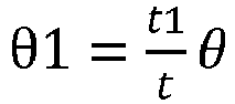
where θ1 is the rotation angle, θ is a preset angle of 100 degrees-113 degrees, and t1 is the motion distance. - A circle center of the third inner-edge trajectory C2D2 is located in the
door 12 and the radius of curvature is 0.61t. A circle center of the third outer-edge trajectory C1D1 is located in thedoor 12 and the radius of curvature is 0.5t. For each of the above two circle centers, a perpendicular distance from the circle center to the first reference plane X is 0.6t, and a perpendicular distance from the circle center to the second reference plane Y is 0.5t. - In carrying out the actual design, taking into account installation deformation and other issues, a reference point may be selected for trajectory design, so as to reserve a tolerance for the edge on the
door 12, ensuring that thedoor 12 is avoided from compressing thecase 11 and from exceeding the side of thecase assembly 100. - Referring to
FIG. 5 ,FIG. 6, and FIG. 7 ,FIG. 5 is a schematic view of a motion trajectory of reference points in the case assembly shown inFIG. 1 ,FIG. 6 is a schematic view of a selection range of an inner reference point in the case assembly shown inFIG. 1 , andFIG. 7 is a schematic view of a selection range of an outer reference point in the case assembly shown inFIG. 1 . - In the present embodiment, an outer reference point R1 and an inner reference point R2 are defined. The outer reference point R1 is located adjacent to the
outer edge 121, and the inner reference point R2 is located adjacent to theinner edge 122. A third reference plane Z is hereby defined, which is parallel to the first reference plane X and passes through theouter edge 121 when in the closed state. - Specifically, a perpendicular distance from the inner reference point R2 to the second reference plane Y and a perpendicular distance from the inner reference point R2 to the first reference plane X are each less than or equal to 0.1t. The inner reference point R2 is selected in a rectangular region centered on the
inner edge 122 with a side length of 0.2t. - Similarly, a perpendicular distance from the outer reference point R1 to the second reference plane Y and a perpendicular distance from the outer reference point R1 to the third reference plane Z are each less than or equal to 0.1t. The outer reference point R1 is selected in a rectangular region centered on the
outer edge 121 with a side length of 0.2t. - The outer reference point R1 may be selected on the
outer edge 121, and the inner reference point R2 may be selected on theinner edge 122. - The motion trajectory design ideas of the inner reference point R2 and the outer reference point R1 are also based on the above trajectory design ideas of the
inner edge 122 and theouter edge 121. During the process of thedoor 12, under the action of thehinge assembly 13, moving from the closed state relative to thecase 11 to an opened state at the first opening angle, the inner reference point R2 moves along a first inner-reference-point trajectory E2F2 toward the side of the second reference plane Y toward the opening, and the outer reference point R1 moves along a first outer-reference-point trajectory E1F1 toward the first reference plane X. - Characteristics of the first inner-reference-point trajectory E2F2 may be all similar to those of the first inner-edge trajectory A2B2, and characteristics of the first outer-reference-point trajectory E1F1 may be all similar to those of the first outer-edge trajectory A1B1, which will not be further described herein.
- For ease of design, in the present embodiment, the first inner-reference-point trajectory E2F2 may be a straight line and the first outer-reference-point trajectory E1F1 may be a straight line. Based on a selected position of the inner reference point R2, the first inner-reference-point trajectory E2F2 may be parallel to the first reference plane X or along the first reference plane X; and based on a selected position of the outer reference point R1, the first outer-reference-point trajectory may be parallel to the second reference plane Y or along the second reference plane Y.
- Further, the first inner-reference-point trajectory E2F2 may be longer than the first outer-reference-point trajectory E1F1, and the ratio of the lengths of the first inner-reference-point trajectory E2F2 and the first outer-reference-point trajectory E1F1 is 3.5 to 4.5.
- Similarly, corresponding to the
inner edge 122 and theouter edge 121, both the outer reference point R1 and the inner reference point R2 may each have a second trajectory and a third trajectory. A second inner-reference-point trajectory F2G2 may have characteristics similar to the second inner-edge trajectory B2C2, and a second outer-reference-point trajectory F1G1 may have characteristics similar to the second outer-edge trajectory B1C1; a third inner-reference-point trajectory G2H2 may have characteristics similar to the third inner-edge trajectory C2D2, and a third outer-reference-point trajectory G1H1 may have characteristics similar to the third outer-edge trajectory C1D1. - During the process of the
door 12 moving from the opened state at the first opening angle to the opened state at the second opening angle relative to thecase 11, the inner reference point R2 moves along the second inner-reference-point trajectory F2G2 toward the side of the second reference plane Y toward the opening and the side of the first reference plane X back to the opening, and the outer reference point R1 moves along the second outer-reference-point trajectory F1G1 toward the first reference plane X. - For ease of design, the second outer-reference-point trajectory F1G1 may be a straight line, and may be along the second reference plane Y or parallel to the second reference plane Y. The second inner-reference-point trajectory F2G2 may be set such that a motion distance of the outer reference point R1 on the second outer-reference-point trajectory F1G1 and a rotation angle of the
door 12 satisfy the following equation.
where θ1 is the rotation angle, θ is a preset angle of 100 degrees-113 degrees, and t1 is the motion distance. - Further, the present disclosure also mitigates the problems of the door compressing the case and exceeding the side of the case assembly by limiting a tangential direction of the motion trajectory of the edge on the door. The relative motion of the door and the case can be converted into the motion of the tangent direction of the motion trajectory. By designing the tangent direction of the motion trajectory of the edge, the relative motion relationship between the door and the case may be limited, such that the door may not excessively compress the doorway and not excessively exceed the side of the case assembly. Based on above, according to a motion trajectory of the tangent direction of the motion trajectory of the edge, a motion trajectory of a fixed point on the case or the door may be determined, and the hinge assembly may thus be designed by inverse deduction according to the motion trajectory of the fixed point. That is, the hinge assemblies that can realize the motion trajectory of the edge in the present disclosure are within the scope of the present disclosure.
- A second implementation is designed from another angle compared with the first implementation, i.e., the tangent direction of the motion trajectory of the edge, and therefore the accompanying drawings and reference numerals in the first implementation are continued to be used. Referring specifically to
FIGS. 3 and4 ,FIG. 3 is a schematic view of a motion trajectory of an edge in the case assembly shown inFIG. 1 , andFIG. 4 is a schematic view illustrating an opening angle of a door relative to a case and a motion trajectory of an edge in the case assembly shown inFIG. 1 . - Further, the tangent direction of the first outer-edge trajectory A1B1 is set perpendicular to the first reference plane X, or the tangent direction of the first outer-edge trajectory A1B1 may be set inclined relative to the first reference plane X at a second angle progressively approaching 90 degrees; the tangent direction of the first inner-edge trajectory A2B2 is set along the first reference plane X, or the tangent direction of the first inner-edge trajectory A2B2 is set inclined relative to the first reference plane X at a first angle of less than or equal to 10 degrees.
- In the present embodiment, the tangent direction of the motion trajectory is limited, and the ratio of the lengths of the first inner-edge trajectory A2B2 and the first outer-edge trajectory ALBA is also limited, so as to ensure that the edges are able to move smoothly and do not exceed a predetermined range.
- Among them, the tangent direction of the first outer-edge trajectory A1B1 is set at the second angle gradually approaching 90 degrees inclined relative to the first reference plane X, ensuring that the
door 12 may not significantly compress thecase 11. The tangent direction of the first inner-edge trajectory A2B2 is set at the first angle of a maximum value of 10 degrees relative to the first reference plane X, ensuring that thedoor 12 may not excessively exceed the side of thecase 11. - Moreover, when the tangent direction of the first outer-edge trajectory A1B1 is perpendicular to the first reference plane X, and the tangent direction of the first inner-edge trajectory A2B2 is set along the first reference plane X, the two trajectories are straight lines. Corresponding to the case where the two trajectories are both straight lines, the first opening angle may be up to 90 degrees, in which case the first inner-edge trajectory A2B2 is longer than the first outer-edge trajectory A1B1, and the ratio of the lengths of the first inner-edge trajectory A2B2 and the first outer-edge trajectory A1B1 is 3.5-4.5.
- The relevant setting of the tangent direction of the first inner-edge trajectory A2B2 determines the extent to which the
inner edge 122 can compress thecase 11. In practice, it is permissible to allow theinner edge 122 to compress thecase 11 to a certain extent. For example, thecase 11 is arranged with a deformable door seal, and the compress to a certain extent, applied by theinner edge 122 to thecase 11, may be ignored. - Similarly, the relevant setting of the tangent direction of the first outer-edge trajectory A1B1 determines the extent to which the
outer edge 121 can exceed the side of thecase 11. In practice, it is permissible to allow the outer edge to exceed the side of thecase 11 by a certain extent. For example, for an embedded use of the case assembly, a gap exists between thecase 11 and an embedding wall, and the gap allows theouter edge 121 to exceed the side of thecase 11 by a certain extent. - Further, during the process of the
door 12 moving from the closed state to the opened state at the first opening angle, the first angle may remain unchanged, i.e., the first inner-edge trajectory A2B2 is in a straight line; alternatively, the first angle varies monotonically in a straight-line form, and the first inner-edge trajectory A2B2 is in the form of an arc. In this way, theinner edge 122 may move smoothly along the straight-line or the arc-shaped first inner-edge trajectory A2B2. - Moreover, a difference between a maximum value and a minimum value of the first angle is less than 5 degrees, i.e., the first inner-edge trajectory A2B2 is overall gentle, further ensuring smooth movement of the
inner edge 122 along the first inner-edge trajectory A2B2. - Similarly, during the process of the
door 12 moving from the closed state to the opened state at the first opening angle, the second angle may remain unchanged, i.e., the first outer-edge trajectory A1B1 is in a straight line; alternatively, the second angle gradually approaches 90 degrees, i.e., the first outer-edge trajectory A1B1 is in the form of an arc. In this way, theouter edge 121 may move smoothly along the straight-line or the arc-shaped first outer-edge trajectory A1B1. - In this way, the process of the
door 12 moving from the closed state to the opened state at the first opening angle is overall smooth, avoiding the situation of sliding jam. - Further, the
inner edge 122 starts to move toward the side of the second reference plane Y toward the opening, and the motion trajectory of theinner edge 122. The radius of curvature of the second inner-edge trajectory B2C2 may gradually decrease. The end point C2 may be located on the side of the first reference plane X back to the opening, and the distance between the end point C2 and the first reference plane X may be greater than or equal to 0.3t. The above design allows room for thedoor 12 to be opened at a greater angle. - In this process, based on the design of the first outer-edge trajectory A1B1, the second outer-edge trajectory B1C1 has a radius of curvature greater than or equal to 5t, and a distance of the second outer-edge trajectory B1C1 exceeding the side of the second reference plane Y back to the opening is less than or equal to the first predetermined distance d1.
- Based on the characteristics of the above trajectory, during the process of the
door 12 moving from the opened state at the first opening angle to the opened state at the second opening angle, thedoor 12 may not compress thecase 11 or excessively exceed the side of the case assembly. - Under the action of the
hinge assembly 13, thedoor 12 may continue to be opened from the second opening angle to the third opening angle relative to thecase 11. During the process of thedoor 12 moving from the opened state at the second opening angle to an opened state at the third opening angle, theinner edge 122 moves along the third inner-edge trajectory C2D2 toward the side of the first reference plane X back to the opening, and theouter edge 121 moves along the third outer-edge trajectory C1D1 toward the side of the second reference plane Y toward the opening. The motion trajectory corresponds to a greater opening angle of thedoor 12. - The third outer-edge trajectory C1D1 and the third inner-edge trajectory C2D2 may specifically be concentrically disposed arcs, the third inner-edge trajectory C2D2 having a radius of curvature of 0.55t-0.67t, and the third outer-edge trajectory C1D1 having a radius of curvature of 0.45t-0.55t.
- After the edges of the
door 12 move along the first inner-edge trajectory A2B2 and the first outer-edge trajectory A1B1, in order to realize a greater opening angle of the door, the edges may move directly along the third outer-edge trajectory C1D1 and the third inner-edge trajectory C2D2, respectively, thereby solving the problem of compressing thecase 11 and exceeding the side of the case assembly. - However, after designing the
hinge assembly 13 based on the first trajectories and the third trajectories, thedoor 12 may be prone to shaking during the rotation process of thedoor 12 under the action of thehinge assembly 13. In order to further optimize and solve the problem of shaking, the second trajectories are added between the first trajectories and the third trajectories, so as to make the motion process of thedoor 12 more stable and smoother. - Considering the design of the
hinge assembly 13, the ratio of the radius of curvature of the third inner-edge trajectory C2D2 to the radius of curvature of the third outer-edge trajectory C1D1 may be 1.22, which is able to prevent structures on thehinge assembly 13 corresponding to the third trajectories from interfering with each other. - Specifically, each set of the three-section trajectory is designed such that the first trajectory corresponds to the first opening angle of 25 degrees to 31 degrees, the second trajectory corresponds to the second opening angle of 57 degrees to 60 degrees, and the third trajectory corresponds to the third opening angle of 122 degrees to 132 degrees.
- The length of the first inner-edge trajectory A2B2 is 0.465t, and the length of the first outer-edge trajectory A1B1 is 0.115t.
- The length of the second outer-edge trajectory B1C1 is 0.2285t, and the second inner-edge trajectory B2C2 is set such that a motion distance of the
outer edge 121 on the second outer-edge trajectory B1C1 and a rotation angle of thedoor 12 relative to thecase 11 satisfy the following equation.
where θ1 is the rotation angle, θ is a preset angle of 100 degrees-113 degrees, and t1 is the motion distance. - A circle center of the third inner-edge trajectory C2D2 is located in the
door 12 and the radius of curvature is 0.61t. A circle center of the third outer-edge trajectory C1D1 is located in thedoor 12 and the radius of curvature is 0.5t. For each of the above two circle centers, a perpendicular distance from the circle center to the first reference plane X is 0.6t, and a perpendicular distance from the circle center to the second reference plane Y is 0.5t. - In carrying out the actual design, taking into account installation deformation and other issues, a reference point may be selected for trajectory design, so as to reserve a tolerance for the edge on the
door 12, ensuring that thedoor 12 is avoided from compressing thecase 11 and from exceeding the side of thecase assembly 100. - Referring to
FIGS. 5 to 9 ,FIG. 5 is a schematic view of a motion trajectory of reference points in the case assembly shown inFIG. 1 ,FIG. 6 is a schematic view of a selection range of an inner reference point in the case assembly shown inFIG. 1 ,FIG. 7 is a schematic view of a selection range of an outer reference point in the case assembly shown inFIG. 1 ,FIG. 8 is a schematic view of an angle of a tangent direction of a trajectory of an inner reference point in the case assembly shown inFIG. 1 , andFIG. 9 is a schematic view of an angle of a tangent direction of a trajectory of an outer reference point in the case assembly shown inFIG. 1 . - In the present embodiment, an inner reference point R2 and an outer reference point R1 are defined. The outer reference point R1 is located adjacent to the
outer edge 121, and the inner reference point R2 is located adjacent to theinner edge 122. A third reference plane Z is hereby defined, which is parallel to the first reference plane X and passes through theouter edge 121 when in the closed state. - Specifically, a perpendicular distance from the inner reference point R2 to the second reference plane Y and a perpendicular distance from the inner reference point R2 to the first reference plane X are each less than or equal to 0.1t. The inner reference point R2 is selected in a rectangular region centered on the
inner edge 122 with a side length of 0.2t. - Similarly, a perpendicular distance from the outer reference point R1 to the second reference plane Y and a perpendicular distance from the outer reference point R1 to the third reference plane Z are each less than or equal to 0.1t. The outer reference point R1 is selected in a rectangular region centered on the
outer edge 121 with a side length of 0.2t. - The outer reference point R1 may be selected on the
outer edge 121, and the inner reference point R2 may be selected on theinner edge 122. - The motion trajectory design ideas of the inner reference point R2 and the outer reference point R1 are also based on the above trajectory design ideas of the
inner edge 122 and theouter edge 121. During the process of thedoor 12, under the action of thehinge assembly 13, moving from the closed state relative to thecase 11 to an opened state at the first opening angle, the inner reference point R2 moves along the first inner-reference-point trajectory E2F2 toward the side of the second reference plane Y toward the opening, and the outer reference point R1 moves along the first outer-reference-point trajectory E1F1 toward the first reference plane X. - Characteristics of the first inner-reference-point trajectory E2F2 may be all similar to those of the first inner-edge trajectory A2B2, and characteristics of the first outer-reference-point trajectory E1F1 may be all similar to those of the first outer-edge trajectory A1B1. The tangent directions of the first inner-reference-point trajectory E2F2 and the second outer-reference-point trajectory E1F1 are specified below.
- Referring to
FIGS. 6 and8 , a coordinate system is established with any point on theinner edge 122 of thedoor 12 when in the closed state as an origin, with a straight line passing through the origin and located on the first reference plane X and perpendicular to the second reference plane Y as an x-axis, and with a straight line passing through the origin and located on the second reference plane Y and perpendicular to the first reference plane X as a y-axis. The inner reference points R2 are taken as (-0.1t,0.1t) (0,0.1t), (0.1t,0.1t), (-0.1t,0), (0,0), (0.1t,0), (-0.1t,-0.1t), (0,-0.1t), (0,-0.1t), (0.1t,0.1t), respectively, and are ordered from left to right onFIG. 8 beginning from the first row corresponding to the first inner-reference-point trajectory E2F2. - As can be seen from the figure, the tangent direction of the first inner-reference-point trajectory E2F2 is set along the first reference plane X, or is set inclined relative to the first reference plane X at a fifth angle of less than or equal to 10 degrees.
- Further, during the process of the
door 12 moving from the closed state to the opened state at the first opening angle, the fifth angle may remain unchanged or monotonically varies in a straight-line form, with a difference between a maximum value and a minimum value of the fifth angle being less than 5 degrees. - Referring to
FIGS. 7 and9 , a coordinate system is established with any point on theouter edge 121 of thedoor 12 when in the closed state as an origin, with a line passing through the origin and located on the third reference plane Z and perpendicular to the second reference plane Y as an x-axis, and with a line passing through the origin and located on the second reference plane Y and perpendicular to the third reference plane Z as a y-axis. The outer reference points R1 are taken as (-0.1t,0.1t), (0,0.1t), (0.1t,0.1t), (-0.1t,0), (0,0), (0.1t,0), (-0.1t,-0.1t), (0,-0.1t), (0,-0.1t), (0.1t,0.1t), respectively, and are ordered from left to right onFIG. 9 beginning from the first row corresponding to the first outer-reference-point trajectory E1F1. - As can be seen from the figure, the tangent direction of the first outer-reference-point trajectory E1F1 is set perpendicular to the first reference plane X, or is set inclined relative to the first reference plane X at a sixth angle gradually approaching 90 degrees.
- Further, the ratio of the lengths of the first inner-reference-point trajectory E2F2 and the first outer-reference-point trajectory E1F1 is 3.5 to 4.5.
- For ease of design, in specific embodiments, the first inner-reference-point trajectory E2F2 may be a straight line and the first outer-reference-point trajectory E1F1 may be a straight line. Based on a selected position of the inner reference point R2, the first inner-reference-point trajectory E2F2 may be parallel to the first reference plane X or along the first reference plane X; and based on a selected position of the outer reference point R1, the first outer-reference-point trajectory may be parallel to the second reference plane Y or along the second reference plane Y. In this way, the tangent direction of the first outer-reference-point trajectory E1F1 is perpendicular to the first reference plane X, and the tangent direction of the first inner-reference-point trajectory E2F2 is set along the first reference plane X.
- Similarly, corresponding to the
inner edge 122 and theouter edge 121, both the outer reference point R1 and the inner reference point R2 may each have a second trajectory and a third trajectory. A second inner-reference-point trajectory F2G2 may have characteristics similar to the second inner-edge trajectory B2C2, and a second outer-reference-point trajectory F1G1 may have characteristics similar to the second outer-edge trajectory B1C1; a third inner-reference-point trajectory G2H2 may have characteristics similar to the third inner-edge trajectory C2D2, and a third outer-reference-point trajectory G1H1 may have characteristics similar to the third outer-edge trajectory C1D1. - The tangent directions of the second inner-reference-point trajectory F2G2 and the second outer-reference-point trajectory F1G1 are specified below.
- Referring to
FIGS. 6 and8 , a coordinate system is established with any point on theinner edge 122 of thedoor 12 when in the closed state as an origin, with a straight line passing through the origin and located on the first reference plane X and perpendicular to the second reference plane Y as an x-axis, and with a straight line passing through the origin and located on the second reference plane Y and perpendicular to the first reference plane X as a y-axis. The inner reference points R2 are taken as (-0.1t,0.1t), (0,0.1t), (0.1t,0.1t), (-0.1t,0), (0,0), (0.1t,0), (-0.1t,-0.1t), (0,-0.1t), (0,-0.1t), (0.1t,0.1t), respectively, and are ordered from left to right onFIG. 8 beginning from the first row corresponding to the second inner-reference-point trajectory F2G2. - As can be seen from the figure, a seventh angle between the tangent direction of the second inner-reference-point trajectory F2G2 and the first reference plane X gradually increases, and a change in angle of the seventh angle corresponding to each unit of opening of the
door 12 gradually increases. - Further, a difference between a maximum value and a minimum value of the seventh angle is greater than or equal to 35 degrees.
- Referring to
FIGS. 7 and9 , a coordinate system is established with any point on theouter edge 121 of thedoor 12 when in the closed state as an origin, with a line passing through the origin and located on the third reference plane Z and perpendicular to the second reference plane Y as an x-axis, and with a line passing through the origin and located on the second reference plane Y and perpendicular to the third reference plane Z as a y-axis. The outer reference points R1 are taken as (-0.1 t,0.1t), (0,0.1t), (0.1t,0.1t), (-0.1t,0), (0,0), (0.1t,0), (-0.1t,-0.1t), (0,-0.1t), (0,-0.1t), (0.1t,0.1t), respectively, and are ordered from left to right onFIG. 9 beginning from the first row corresponding to the second outer-reference-point trajectory F1G1. - As can be seen from the figure, the tangent direction of the second outer-reference-point trajectory F1G1 is set perpendicular to the first reference plane X, or is set inclined relative to the first reference plane X at an eighth angle between 70 degrees and 110 degrees.
- Further, during the process of the
door 12 moving from the opened state at the first opening angle to the opened state at the second opening angle, the eighth angle may remain unchanged or monotonically varies in a straight-line form, with a difference between a maximum value and a minimum value of the eighth angle being less than or equal to 10 degrees. - Under the action of the
hinge assembly 13, during the process of thedoor 12 moving from the opened state at the first opening angle to the opened state at the second opening angle relative to thecase 11, the inner reference point R2 moves along the second inner-reference-point trajectory F2G2 toward the side of the second reference plane Y toward the opening and the side of the first reference plane X back to the opening, and the outer reference point R1 moves along the second outer-reference-point trajectory F1G1 toward the first reference plane X. - For ease of design, in specific embodiments, the second outer-reference-point trajectory F1G1 may be a straight line, and may be along the second reference plane Y or parallel to the second reference plane Y. The second inner-reference-point trajectory F2G2 may be set such that a motion distance of the outer reference point R1 on the second outer-reference-point trajectory F1G1 and a rotation angle of the
door 12 satisfy the following equation.
where θ1 is the rotation angle, θ is a preset angle of 100 degrees-113 degrees, and t1 is the motion distance. - Further, the present disclosure also mitigates the problem of the door compressing the case and exceeding the side of the case assembly by limiting a motion trajectory of a motion instantaneous center of the door. The relative motion of the door and the case can be converted into the motion of the instantaneous center of the door. By designing the motion trajectory of the instantaneous center, the relative motion relationship between the door and the case may be limited, such that the door may not excessively compress the doorway and not excessively exceed the side of the case assembly. Based on above, after designing the motion trajectory of the instantaneous center, a motion trajectory of a fixed point on the case or the door may be determined according to the motion trajectory of the instantaneous center, and the hinge assembly may thus be designed by inverse deduction according to the motion trajectory of the fixed point. That is, the hinge assemblies that can realize the motion trajectory of the motion instantaneous center and the motion trajectory of the edge in the present disclosure is within the scope of the present disclosure.
- A third implementation is designed from another angle compared with the first implementation, i.e., the motion trajectory of the motion instantaneous center of the door, and therefore the accompanying drawings and reference numerals in the first implementation are continued to be used. Referring specifically to
FIG. 10, FIG. 10 is a schematic view of a motion-instantaneous-center trajectory of a motion instantaneous center of a door in the case assembly shown inFIG. 1 according to a third implementation of the present disclosure. - In the present embodiment, the motion trajectory of the motion instantaneous center of the
door 12 is limited. Specifically, the motion instantaneous center starts from theouter edge 121 along a first motion-instantaneous-center trajectory A3B3 toward the first reference plane X and simultaneously toward the side of the second reference plane Y toward the opening, thereby ensuring that thedoor 12 may not excessively compress thecase 11 and not excessively exceed the side of thecase 11. - The relevant setting of the motion trajectory of the motion instantaneous center of the
door 12 determine the extent to which theinner edge 122 can compress thecase 11 and the extent to which theouter edge 121 can exceed the side of the case assembly. In practice, it is permissible to allow theinner edge 122 to compress thecase 11 to a certain extent. For example, when thecase 11 is arranged with a deformable door seal, and the compress to a certain extent, applied by theinner edge 122 to thecase 11, may be ignored. Similarly, it is permissible to allow the outer edge to exceed the side of thecase assembly 100 by a certain degree. For example, for an embedded use of the case assembly, a gap exists between thecase 11 and an embedding wall, and the gap allows theouter edge 121 to exceed the side of thecase 11 by a certain extent. - It should be noted that in rigid-body planar motion, as long as the angular velocity ω of any cross-sectional figure S (or an extension thereof) on the rigid body parallel to a fixed plane is not zero at any instant, there must be a point P', called an instantaneous center of velocity, at which the velocity is zero. At the instant, in terms of velocity distribution, the sectional figure (or an extension thereof) appears to be rotating only about a point P on the fixed plane coinciding with P', the point P being called an instantaneous center of rotation. The motion instantaneous center in the present embodiment may be the instantaneous center of rotation or the instantaneous center of velocity of the
door 12. - Further, an angle between a perpendicular line connecting the motion instantaneous center and the
inner edge 122 and the first reference plane X is between 85 and 95 degrees. Within this range, it may be ensured that the first inner-edge trajectory A2B2 of theinner edge 122 moves toward the side of the second reference plane Y toward the opening and does not excessively compress thecase 11. A maximum value and a minimum value of the angle between the perpendicular line connecting the motion instantaneous center and theinner edge 122 and the first reference plane X during the opening of the door are specifically defined as 95 degrees and 85 degrees, respectively, which may ensure that thedoor 12 may not excessively compress thecase 11 - Similarly, an angle between a perpendicular line connecting the motion instantaneous center and the
outer edge 121 and the second reference plane Y is between 85 and 95 degrees. Within this range, it may be ensured that the first outer-edge trajectory A1B1 of theouter edge 122 moves toward the first reference plane X and does not excessively exceed the side of thecase 11. A maximum value and a minimum value of the angle between the perpendicular line connecting the motion instantaneous center and theouter edge 121 and the second reference plane Y during the opening of the door are specifically defined as95 degrees and 85 degrees, respectively, which may ensure that thedoor 12 may not excessively exceed the side of thecase 11. - In some embodiments, the perpendicular line connecting the motion instantaneous center and the
inner edge 122 is perpendicular to the first reference plane X, and during the opening process of thedoor 12 to the first angle, the first inner-edge trajectory A2B2 of theinner edge 122 is in a straight line and is parallel to the first reference plane X. The perpendicular line connecting the motion instantaneous center and theouter edge 121 is perpendicular to the second reference plane Y, and during the opening process of thedoor 12 to the first angle, the first outer-edge trajectory A1B1 of theouter edge 121 is in a straight line and parallel to the second reference plane Y. The present embodiment ensures that the edges are able to move smoothly by limiting the positional relationships of the motion instantaneous center with theinner edge 122 and theouter edge 121, thereby ensuring that thedoor 12 does not compress thecase 11 and not exceed the side of thecase 11. - In some embodiments, during the opening process of the
door 12 to the first angle, the first motion-instantaneous-center trajectory A3B3 of the motion instantaneous center of thedoor 12 is in the form of an arc, a circle center of the arc is located at the midpoint of a perpendicular line connecting theinner edge 122 and theouter edge 121, and the diameter of the arc is a perpendicular distance between theinner edge 122 and theouter edge 121. When the motion instantaneous center of thedoor 12 moves along the first motion-instantaneous-center trajectory A3B3, the first inner-edge trajectory A2B2 of theinner edge 122 is in a straight line and parallel to the first reference plane X, and the first outer-edge trajectory A1B1 of theouter edge 121 is straight and parallel to the second reference plane Y. The present embodiment ensures that the edges are able to move smoothly by limiting the first motion-instantaneous-center trajectory of the motion instant center, thereby ensuring that thedoor 12 does not compress thecase 11 and not exceed the side of thecase 11. - Further, an angle between a line connecting the motion instantaneous center and the circle center and a line connecting the circle center and a start point of the first motion-instantaneous-center trajectory A3B3 is equal to an actual opening angle of the
door 12 relative to thecase 11. The movement of the motion instantaneous center varies regularly with the first opening angle of thedoor 12, and the process of thedoor 12 opening to the first opening angle is overall smooth, avoiding the situation of sliding jam and ensuring that thedoor 12 does not compress thecase 11 and not exceed the side of thecase 11. Specifically, the first opening angle is between 25 degrees and 31 degrees; for example, the first opening angle may be 25 degrees, 28 degrees, 30 degrees, or 31 degrees. Within the first opening angle, it may be ensured that thedoor 12 does not compress thecase 11 and not exceed the side of thecase 11. - Overall, in the present embodiment, during the process of the
door 12, under the action of thehinge assembly 13, moving from the closed state relative to thecase 11 to the opened state at the first opening angle, the motion instantaneous center of thedoor 12 starts from theouter edge 121 and moves along the first motion-instantaneous-center trajectory A3B3 toward the first reference plane X, and simultaneously toward the side of the second reference plane Y toward the opening. The first motion-instantaneous-center trajectory A3B3 has certain characteristics, and thedoor 12 moves according to the first motion-instantaneous-center trajectory A3B3, so as to attenuate or even avoid thedoor 12 from compressing thecase 11 and from exceeding the side of thecase 11. - That is, during the opening of the
door 12 to the first opening angle, theinner edge 122 of thedoor 12 does not compress thecase 11 and does not move excessively away from thecase 11, while theouter edge 121 does not exceed the side of thecase assembly 100 and does not move excessively toward the side of the second reference plane Y toward the opening. The above design allows thedoor 12 to be opened without significant displacement, and the movement of thedoor 12 is more stable. - In the present embodiment, when the motion instantaneous center of the
door 12 moves along the first motion-instantaneous-center trajectory until thedoor 12 is opened at 90 degrees, thedoor 12 may not be able to be further opened at a greater angle, and a maximum opening angle of thedoor 12 is generally required to be greater than 90 degrees. Therefore, after the motion instantaneous center of thedoor 12 moves along the first inner motion-instantaneous-center trajectory until thedoor 12 is opened at an angle less than 90 degrees, the motion instantaneous center may move along another motion trajectory such that thedoor 12 may be further opened at an angle more than 90 degrees. - As mentioned before, the
door 12 may move along a different trajectory after being opened at the first opening angle. In the present embodiment, during the process of thedoor 12, under the action of thehinge assembly 13, moving from the opened state at the first opening angle to the opened state at the second opening angle relative to thecase 11, the motion instantaneous center moves along a second motion-instantaneous-center trajectory B3C3 toward the first reference plane X. An angle between a tangent direction of the second motion-instantaneous-center trajectory B3C3 and the first reference plane X is between 85 degrees and 95 degrees. - Based on the above characteristics of the trajectories, during the process of the
door 12 moving from the opened state at the first opening angle to the opened state at the second opening angle, thedoor 12 may not compress thecase 11 or excessively exceed the side of thecase 11, allowing room for thedoor 12 to be opened at a greater angle. - The motion instantaneous center moves along the second motion-instantaneous-center trajectory B3C3 toward the first reference plane X, and the tangent direction of the second motion-instantaneous-center trajectory B3C3 is at an angle between 85 degrees and 95 degrees relative to the first reference plane X. Within this range, since the motion instantaneous center is always located on a side of the
outer edge 121 back to the second reference plane Y, it may be ensured that theouter edge 122 does not excessively exceed the side of thecase 11. Since the instantaneous motion center is always located on the side of theinner edge 121 back to the first reference plane X, it may be ensured that the first inner-edge trajectory A2B2 of theinner edge 122 moves toward the side of the second reference plane Y toward the opening and does not excessively compress thecase 11. - Further, the second motion-instantaneous-center trajectory B3C3 is in a straight line and is set perpendicular to the first reference plane X. During the process of the
door 12 moving from the opened state at the first opening angle to the opened state at the second opening angle, the second outer-edge trajectory B1C1 of theouter edge 121 is a straight line, and the second outer-edge trajectory B1C1 is set parallel to the second reference plane Y, ensuring that theouter edge 121 does not excessively exceed the side of thecase 11; theinner edge 122 moves away from the first reference plane X, ensuring that thedoor 12 does not excessively compress thecase 11. The end point C2 of the second inner-edge trajectory B2C2 is located on the side of the first reference plane X back to the opening, allowing room for thedoor 12 to be opened at a greater angle. Moreover, the second motion-instantaneous-center trajectory B3C3 of the motion instantaneous center varies regularly with the second opening angle of thedoor 12, and the process of thedoor 12 moving from the opened state at the first opening angle to the opened state at the second opening angle is overall smooth, avoiding the situation of sliding jam. - Further, during the process of the
door 12 moving from the opened state at the first opening angle to the opened state at the second opening angle, the angle between the perpendicular line connecting the motion instantaneous center and theouter edge 121 and the second reference plane Y is between 85 degrees and 95 degrees. Within this range, it may be ensured that the second outer-edge trajectory B1C1 of theouter edge 122 moves toward the first reference plane X and does not excessively exceed the side of thecase 11. A maximum value and a minimum value of the angle between the perpendicular line connecting the motion instantaneous center and theouter edge 121 and the second reference plane Y during the opening of the door are specifically defined as95 degrees and 85 degrees, respectively, which may ensure that thedoor 12 may not excessively exceed the side of thecase 11. When the perpendicular line connecting the motion instantaneous center and theouter edge 121 is perpendicular to the second reference plane Y, i.e., when the angle between the perpendicular line connecting the motion instantaneous center and theouter edge 121 and the second reference plane Y is 90 degrees, the second outer-edge trajectory B1C1 of theouter edge 121 is a straight line and perpendicular to the first reference plane X during the process of the motion instantaneous center of thedoor 12 moving along the second motion-instantaneous-center trajectory B3C3, ensuring that thedoor 12 may not excessively exceed the side of thecase 11. - In addition, during the process of the
door 12 moving from the opened state at the first opening angle to the opened state at the second opening angle, the perpendicular distance from theinner edge 122 to the motion instantaneous center gradually decreases, such that the radius of curvature of the second inner-edge trajectory B2C2 of theinner edge 122 gradually decreases, and the end point C2 is located on the side of the first reference plane X back to the opening. Therefore, there is room for thedoor 12 to be opened to a greater angle, and it may be ensured that thedoor 12 may not compress the case. - Based on the above characteristics of the trajectories, during the process of the
door 12 moving from the opened state at the first opening angle to the opened state at the second opening angle, thedoor 12 may not compress thecase 11 or excessively exceed the side of thecase 11. - Specifically, the second opening angle is between 57 degrees and 60 degrees, and the first opening angle may be 57 degrees, 58 degrees, 59 degrees, or 60 degrees, and the like. Within the second opening angle, it may be ensured that the
door 12 may not compress thecase 11 or exceed the side of thecase 11. - Under the action of the
hinge assembly 13, thedoor 12 may continue to be opened from the second opening angle to a third opening angle relative to thecase 11. During the process of thedoor 12 moving from the opened state at the second opening angle to an opened state at the third opening angle, the motion instantaneous center may remain unchanged, and thedoor 12 is rotated around the motion instantaneous center as a whole. The motion trajectory corresponds to a greater opening angle of thedoor 12. - As mentioned above, during the process of the
door 12 moving from the opened state at the second opening angle to the opened state at the third opening angle relative to thecase 11, the motion instantaneous center remains unchanged at the end point of the second motion-instantaneous-center, and the third inner-edge trajectory C2D2 of theinner edge 122 and the third outer-edge trajectory C1D1 of theouter edge 121 are specified to be concentrically disposed arcs. - Based on the above characteristics of the trajectories, during the process of the
door 12 moving from the opened state at the second opening angle to the opened state at the third opening angle, thedoor 12 may not compress thecase 11 or excessively exceed the side of thecase 11. - After the motion of the motion instantaneous center of the
door 12 along the first motion-instantaneous-center trajectory A3B3, in order to realize a greater opening angle, the motion instantaneous center may move directly along a third motion-instantaneous-center trajectory C3D3 with the end point of the first motion-instantaneous-center trajectory A3B3 as a start, thereby solving the problem of compressing thecase 11 and exceeding the side of thecase 11. - However, after designing the
hinge assembly 13 based on the first motion-instantaneous-center trajectory A3B3 and the third motion-instantaneous-center trajectory, thedoor 12 may be prone to shaking during the rotation process of thedoor 12 under the action of thehinge assembly 13. In order to further optimize and solve the problem of shaking, the second motion-instantaneous-center trajectory B3C3 is added between the first motion-instantaneous-center trajectory A3B3 and the third motion-instantaneous-center trajectory, so as to make the motion process of thedoor 12 more stable and smoother. - Starting from the design of the motion trajectory of the edge of the
door 12, based on the design principle of relative motion, a variety of hinge assembly structures may be designed. As shown inFIGS. 11-13 ,FIG. 11 is a structural schematic view of a case assembly according to a fourth implementation of the present disclosure,FIG. 12 is a schematic view of a hinge shaft structure of a hinge assembly in the case assembly shown inFIG. 11 , andFIG. 14 is a schematic view of a hinge slot structure of a hinge assembly in the case assembly shown inFIG. 11 . - The fourth implementation specifies the structure of the hinge assembly as compared to the first implementation shown in
FIG. 1 , and therefore the reference numerals continue to follow those in the first implementation. The design of thehinge assembly 13 in thecase assembly 100 of the present embodiment is to convert the motion trajectories of the edges of thedoor 12 into the motion trajectories of two fixed points on thedoor 12 or thecase 11, and design the corresponding mechanical structure based on the motion trajectories of the two fixed points. Thehinge assembly 13 comprises afirst guiding mechanism 135 and asecond guiding mechanism 136 to realize the motion trajectories of the two fixed points, i.e., the two guiding mechanisms may cooperate to make the edges of thedoor 12 move along the predetermined trajectories. - Referring to
FIGS. 11-13 , the guiding mechanism is a slot-shaft cooperation structure. Obviously, the guiding mechanisms designed based on the motion trajectories may be linking rod structures, slot-shaft + linking rod structure, etc. - The
hinge assembly 13 in the present embodiment is a dual-shaft and dual-slot design, and the two slots are defined on thedoor 12 and the two shafts are arranged on thecase 11. Similarly, in other embodiments, the two slots may be defined on thecase 11 and the two shafts are arranged on thedoor 12; or thedoor 12 is arranged with one shaft and one slot, and thecase 11 is arranged with the other shaft and the other slot; or, as mentioned above, the slot-shaft structures on thedoor 12 and thecase 11 may be converted into connecting rod structures, or shaft + track sliding structures, etc. - Specifically, the
hinge assembly 13 of the present embodiment comprises afirst hinge shaft 131 and asecond hinge shaft 132 arranged on thecase 11, and afirst hinge slot 133 and asecond hinge slot 134 defined on thedoor 12. Thefirst hinge shaft 131 is movable within thefirst hinge slot 133, and thefirst hinge shaft 131 and thefirst hinge slot 133 constitute thefirst guiding mechanism 135. Thesecond hinge shaft 132 is movable within thesecond hinge slot 134, and thesecond hinge shaft 132 and thesecond hinge slot 134 constitute thesecond guiding mechanism 136. In this way, the motion trajectories of the edges of the door as shown inFIG. 3 are realized, which then solves the problems of thedoor 12 compressing thecase 11 and exceeding the side of thecase assembly 100. - During the opening process of the
door 12, a motion state of thehinge assembly 13 is illustrated inFIGS. 14-17 , whereinFIG. 14 is a state schematic view of a hinge assembly in the case assembly shown inFIG. 11 when a door is in a closed state relative to a case,FIG. 15 is a state schematic view of a hinge assembly in the case assembly shown inFIG. 11 when a door is in an opened state relative to a case at a first opening angle,FIG. 16 is a state schematic view of a hinge assembly in the case assembly shown inFIG. 11 when a door is in an opened state relative to a case at a second opening angle, andFIG. 17 is a state schematic view of a hinge assembly in the case assembly shown inFIG. 11 when a door is in an opened state relative to a case at a third opening angle. - The
first hinge slot 133 in the present embodiment comprises afirst slot segment 1331, asecond slot segment 1332, and athird slot segment 1333; thesecond hinge slot 134 comprises afourth slot segment 1341 and afifth slot segment 1342. - During the process of the
door 12 moving from a closed state relative to thecase 11 to an opened state at a first opening angle, thefirst hinge shaft 131 moves along thefirst slot section 1331 and thesecond hinge shaft 132 moves along thefourth slot section 1341, correspondingly realizing the first trajectories inFIG. 3 . - During the process of the
door 12 moving from the opened state at the first opening angle to an opened state at a second opening angle relative to thecase 11, thefirst hinge shaft 131 moves along thesecond slot segment 1332 and thesecond hinge shaft 132 moves along thefifth slot segment 1342, correspondingly realizing the second trajectories inFIG. 3 . - During the process of the
door 12 moving from the opened state at the second opening angle to an opened state at a third opening angle relative to thecase 11, thefirst hinge shaft 131 moves along thethird slot segment 1333 and thesecond hinge shaft 132 does not undergo a positional change at a bottom end of thefifth slot segment 1342, correspondingly realizing the third trajectories inFIG. 3 . - The
first hinge slot 133 and thesecond hinge slot 134 have a tendency to separate from each other in a direction toward the first reference plane. Thefirst slot segment 1331 is farther away from the second reference plane Y compared to thefourth slot segment 1341 and extends toward the second reference plane Y and the first reference plane X. An angle between a tangent direction of thefirst slot segment 1331 and the first reference plane X is greater than an angle between a tangent direction of thefourth slot segment 1341 and the first reference plane X. - The design of the
hinge assembly 13 in the present embodiment allows thedoor 12 to be opened stably and smoothly relative to thecase 11, without compressing thecase 11 or exceeding the side of thecase assembly 100, which facilitates embedded use. - In summary, for the present disclosure, corresponding to the different trajectories of the edges of the door, different hinge assemblies may be designed to reduce the problems of door compressing the case and exceeding the side of the case assembly when the door is opened. The design of the above case assembly may be applied to products such as refrigerators, cabinets and other products that have a door and have problems of compressing the case and interference when exceeding the case assembly.
- The present disclosure further proposes a refrigeration device, the refrigeration device comprising the
above case assembly 100, i.e., with thedoor 12, thecase 11, and thehinge assembly 13 between thedoor 12 and thecase 11. The refrigeration device may be a refrigerator, a freezer, a wine cooler, a freshness cabinet, etc. - The foregoing is only some embodiments of the present disclosure and is not intended to limit the scope of the present disclosure, and any equivalent structure or equivalent process transformation utilizing the contents of the specification and the accompanying drawings of the present disclosure, or directly or indirectly utilized in other related technical fields, are all reasonably comprised in the scope of the present disclosure.
Claims (100)
- A case assembly, comprising:a case, defining a holding space; wherein the holding space has an opening;a door, blocking the opening; anda hinge assembly, arranged on a pivot side of the case and pivotally connected to the door and the case;wherein the door has an outer edge and an inner edge on the pivot side; in condition of the door being in a closed state relative to the case, the inner edge is closer to the case compared to the outer edge; a first reference plane and a second reference plane are defined for the door; the first reference plane is parallel to a plane where the opening is located and passes through the inner edge in the closed state; the second reference plane is perpendicular to the plane where the opening is located and passes through the outer edge in the closed state;during a process of the door, under an action of the hinge assembly, moving from the closed state to an opened state at a first opening angle relative to the case, the outer edge moves toward the first reference plane along a first outer-edge trajectory, and the inner edge moves toward a side of the second reference plane toward the opening along a first inner-edge trajectory;wherein the first outer-edge trajectory has a radius of curvature greater than or equal to 5t, and a distance of the first outer-edge trajectory exceeding a side of the second reference plane back to the opening is less than or equal to a first predetermined distance; the first inner-edge trajectory has a radius of curvature greater than or equal to 100t, and a distance of the first inner-edge trajectory exceeding a side of the first reference plane toward the opening is less than or equal to a second predetermined distance; wherein the t is a thickness of the door.
- The case assembly according to claim 1, wherein the first opening angle is between 25 degrees and 31 degrees, the first predetermined distance is 3mm, and the second predetermined distance is 1mm.
- The case assembly according to claim 1, wherein an end point of the first inner-edge trajectory is located on the first reference plane, or the end point of the first inner-edge trajectory is located on a side of the first reference plane back to the opening and a distance between the end point of the first inner-edge trajectory and the first reference plane is less than or equal to 0.058t;
an end point of the first outer-edge trajectory is located on the second reference plane, or the end point of the first outer-edge trajectory is located on the side of the second reference plane toward the opening and a distance between the end point of the first outer-edge trajectory and the second reference plane is less than or equal to 0.135t. - The case assembly according to claim 1, wherein a length of the first inner-edge trajectory is greater than a length of the first outer-edge trajectory, and a ratio of the length of the first inner-edge trajectory to the length of the first outer-edge trajectory is 3.5 to 4.5.
- The case assembly according to claim 1, wherein an outer reference point and an inner reference point are defined for the door; the outer reference point is located adjacent to the outer edge, and the inner reference point is located adjacent to the inner edge;during the process of the door, under the action of the hinge assembly, moving from the closed state to the opened state at the first opening angle relative to the case, the inner reference point moves along a first inner-reference-point trajectory toward the side of the second reference plane toward the opening, and the outer reference point moves along a first outer-reference-point trajectory toward the first reference plane;each of the first inner-reference-point trajectory and the first outer-reference-point trajectory is a straight line.
- The case assembly according to claim 5, wherein the first inner-reference-point trajectory is parallel to the first reference plane or along the first reference plane, and the first outer-reference-point trajectory is parallel to the second reference plane or along the second reference plane.
- The case assembly according to claim 6, wherein a length of the first inner-reference-point trajectory is greater than a length of the first outer-reference-point trajectory, and a ratio of the length of the first inner-reference-point trajectory to the length of the first outer-reference-point trajectory is 3.5 to 4.5.
- The case assembly according to claim 5, wherein a perpendicular distance from the inner reference point to the second reference plane and a perpendicular distance from the inner reference point to the first reference plane are each less than or equal to 0.1t;
a perpendicular distance from the outer reference point to the second reference plane and a perpendicular distance from the outer reference point to a third reference plane are each less than or equal to 0.1t; wherein the third reference plane is parallel to the first reference plane and passes through the outer edge in the closed state. - The case assembly according to claim 8, wherein the outer reference point is located on the outer edge, and the inner reference point is located on the inner edge.
- The case assembly according to claim 1, wherein during a process of the door, under the action of the hinge assembly, moving from the opened state at the first opening angle to an opened state at a second opening angle relative to the case, the outer edge moves along a second outer-edge trajectory toward the first reference plane, and the inner edge moves along a second inner-edge trajectory toward the side of the second reference plane toward the opening and a side of the first reference plane back to the opening;
the second outer-edge trajectory has a radius of curvature greater than or equal to 5t, and a distance of the second outer-edge trajectory exceeding the side of the second reference plane back to the opening is less than or equal to the first predetermined distance; a radius of curvature of the second inner-edge trajectory gradually decreases, an end point of the second inner-edge trajectory is located on the side of the first reference plane back to the opening, and a distance between the end point of the second inner-edge trajectory and the first reference plane is greater than or equal to 0.3t. - The case assembly according to claim 10, wherein the second opening angle is between 57 degrees and 60 degrees.
- The case assembly according to claim 10, wherein an outer reference point and an inner reference point are defined for the door; the outer reference point is located adjacent to the outer edge, and the inner reference point is located adjacent to the inner edge;during the process of the door, under the action of the hinge assembly, moving from the opened state at the first opening angle to the opened state at the second opening angle relative to the case, the inner reference point moves along a second inner-reference-point trajectory toward the side of the second reference plane toward the opening and the side of the first reference plane back to the opening, and the outer reference point moves along a second outer-reference-point trajectory toward the first reference plane;the second outer-reference-point trajectory is a straight line, and the second inner-reference-point trajectory is set such that a motion distance of the outer reference point on the second outer-reference-point trajectory and a rotation angle of the door satisfy:
 where θ1 is the rotation angle, θ is a preset angle of 100 degrees-113 degrees, and t1 is the motion distance.
 - The case assembly according to claim 12, wherein the second outer-reference-point trajectory is along the second reference plane or parallel to the second reference plane.
- The case assembly according to claim 10, wherein during a process of the door, under the action of the hinge assembly, moving from the opened state at the second opening angle to an opened state at a third opening angle relative to the case, the inner edge moves along a third inner-edge trajectory toward the side of the first reference plane back to the opening, and the outer edge moves along a third outer-edge trajectory toward the side of the second reference plane toward the opening;
the third outer-edge trajectory and the third inner-edge trajectory are concentrically disposed arcs, the third inner-edge trajectory having a radius of curvature of 0.55t-0.67t, and the third outer-edge trajectory having a radius of curvature of 0.45t-0.55t. - The case assembly according to claim 14, wherein a ratio of the radius of curvature of the third inner-edge trajectory to the radius of curvature of the third outer-edge trajectory is 1.22.
- The case assembly according to claim 14, wherein a circle center of the third inner-edge trajectory is located in the door and a circle center of the third outer-edge trajectory is located in the door; for each of the circle center of the third inner-edge trajectory and the circle center of the third outer-edge trajectory, a distance from the circle center to the first reference plane is 0.6t, and a distance from the circle center to the second reference plane is 0.5t.
- The case assembly according to claim 14, wherein the third opening angle is between 122 degrees and 132 degrees.
- The case assembly according to claim 1, wherein the thickness of the door is greater than or equal to 2cm.
- A case assembly, comprising:a case, defining a holding space; wherein the holding space has an opening;a door, blocking the opening; anda hinge assembly, arranged on a pivot side of the case and pivotally connected to the door and the case;wherein the door has an outer edge and an inner edge on the pivot side; a first reference plane and a second reference plane are defined for the door; the first reference plane is parallel to a plane where the opening is located and passes through the inner edge in a closed state; the second reference plane is perpendicular to the plane where the opening is located and passes through the outer edge in the closed state; the first reference plane and the second reference plane remain stationary with respect to the case during a process of the door being opened relative to the case;during a process of the door, under an action of the hinge assembly, moving from an opened state at a first opening angle to an opened state at a second opening angle relative to the case, the outer edge moves along a second outer-edge trajectory toward the first reference plane, and the inner edge moves along a second inner-edge trajectory toward a side of the second reference plane toward the opening and a side of the first reference plane back to the opening;the second outer-edge trajectory has a radius of curvature greater than or equal to 5t, and a distance of the second outer-edge trajectory exceeding a side of the second reference plane back to the opening is less than or equal to a first predetermined distance; a radius of curvature of the second inner-edge trajectory gradually decreases.
- The case assembly according to claim 19, wherein an end point of the second inner-edge trajectory is located on the side of the first reference plane back to the opening, and a distance between the end point of the second inner-edge trajectory and the first reference plane is greater than or equal to 0.3t.
- The case assembly according to claim 19, wherein a difference between the first opening angle and the second opening angle is between 25 degrees and 60 degrees.
- The case assembly according to claim 19, wherein the first opening angle is between 25 degrees and 31 degrees, the second opening angle is between 57 degrees and 60 degrees, and the first predetermined distance is between 0mm and 4mm.
- The case assembly according to claim 19, wherein an outer reference point and an inner reference point are defined for the door; the outer reference point is located adjacent to the outer edge, and the inner reference point is located adjacent to the inner edge;during the process of the door, under the action of the hinge assembly, moving from the opened state at the first opening angle to the opened state at the second opening angle relative to the case, the inner reference point moves along a second inner-reference-point trajectory toward the side of the second reference plane toward the opening and the side of the first reference plane back to the opening, and the outer reference point moves along a second outer-reference-point trajectory toward the first reference plane;the second outer-reference-point trajectory is a straight line, and the second inner-reference-point trajectory is set such that a motion distance of the outer reference point on the second outer-reference-point trajectory and a rotation angle of the door satisfy:
 where θ1 is the rotation angle, θ is a preset angle of 100 degrees-113 degrees, and t1 is the motion distance.
 - The case assembly according to claim 23, wherein the second outer-reference-point trajectory is along the second reference plane or parallel to the second reference plane.
- The case assembly according to claim 23, wherein a perpendicular distance from the inner reference point to the second reference plane and a perpendicular distance from the inner reference point to the first reference plane are each less than or equal to 0.1t;
a perpendicular distance from the outer reference point to the second reference plane and a perpendicular distance from the outer reference point to a third reference plane are each less than or equal to 0.1t; wherein the third reference plane is parallel to the first reference plane and passes through the outer edge in the closed state. - The case assembly according to claim 25, wherein the outer reference point is located on the outer edge, and the inner reference point is located on the inner edge.
- The case assembly according to claim 19, wherein during a process of the door, under the action of the hinge assembly, moving from the closed state to the opened state at the first opening angle relative to the case, the outer edge moves toward the first reference plane along a first outer-edge trajectory, and the inner edge moves toward the side of the second reference plane toward the opening along a first inner-edge trajectory;
wherein the first outer-edge trajectory has a radius of curvature greater than or equal to 5t, and a distance of the first outer-edge trajectory exceeding a side of the second reference plane back to the opening is less than or equal to the first predetermined distance; the first inner-edge trajectory has a radius of curvature greater than or equal to 100t, and a distance of the first inner-edge trajectory exceeding a side of the first reference plane toward the opening is less than or equal to a second predetermined distance; wherein the t is a thickness of the door. - The case assembly according to claim 27, wherein the second predetermined distance is between 0mm and 2mm.
- The case assembly according to claim 27, wherein an end point of the first inner-edge trajectory is located on the first reference plane, or the end point of the first inner-edge trajectory is located on a side of the first reference plane back to the opening and a distance between the end point of the first inner-edge trajectory and the first reference plane is less than or equal to 0.058t;
an end point of the first outer-edge trajectory is located on the second reference plane, or the end point of the first outer-edge trajectory is located on the side of the second reference plane toward the opening and a distance between the end point of the first outer-edge trajectory and the second reference plane is less than or equal to 0.135t. - The case assembly according to claim 27, wherein a length of the first inner-edge trajectory is greater than a length of the first outer-edge trajectory, and a ratio of the length of the first inner-edge trajectory to the length of the first outer-edge trajectory is 3.5 to 4.5.
- The case assembly according to claim 27, wherein an outer reference point and an inner reference point are defined for the door; the outer reference point is located adjacent to the outer edge, and the inner reference point is located adjacent to the inner edge;during the process of the door, under the action of the hinge assembly, moving from the closed state to the opened state at the first opening angle relative to the case, the inner reference point moves along a first inner-reference-point trajectory toward the side of the second reference plane toward the opening, and the outer reference point moves along a first outer-reference-point trajectory toward the first reference plane;each of the first inner-reference-point trajectory and the first outer-reference-point trajectory is a straight line.
- The case assembly according to claim 31, wherein the first inner-reference-point trajectory is parallel to the first reference plane or along the first reference plane, and the first outer-reference-point trajectory is parallel to the second reference plane or along the second reference plane.
- The case assembly according to claim 32, wherein a length of the first inner-reference-point trajectory is greater than a length of the first outer-reference-point trajectory, and a ratio of the length of the first inner-reference-point trajectory to the length of the first outer-reference-point trajectory is 3.5 to 4.5.
- The case assembly according to claim 19, wherein during a process of the door, under the action of the hinge assembly, moving from the opened state at the second opening angle to an opened state at a third opening angle relative to the case, the inner edge moves along a third inner-edge trajectory toward the side of the first reference plane back to the opening, and the outer edge moves along a third outer-edge trajectory toward the side of the second reference plane toward the opening;
the third outer-edge trajectory and the third inner-edge trajectory are concentrically disposed arcs, the third inner-edge trajectory having a radius of curvature of 0.55t-0.67t, and the third outer-edge trajectory having a radius of curvature of 0.45t-0.55t. - The case assembly according to claim 34, wherein a ratio of the radius of curvature of the third inner-edge trajectory to the radius of curvature of the third outer-edge trajectory is 1.22.
- The case assembly according to claim 34, wherein a circle center of the third inner-edge trajectory is located in the door and a circle center of the third outer-edge trajectory is located in the door; for each of the circle center of the third inner-edge trajectory and the circle center of the third outer-edge trajectory, a distance from the circle center to the first reference plane is 0.6t, and a distance from the circle center to the second reference plane is 0.5t.
- The case assembly according to claim 34, wherein the third opening angle is between 122 degrees and 132 degrees.
- The case assembly according to claim 19, wherein the thickness of the door is greater than or equal to 2cm.
- A case assembly, comprising:a case, defining a holding space; wherein the holding space has an opening;a door, blocking the opening; anda hinge assembly, arranged on a pivot side of the case and pivotally connected to the door and the case;wherein the door has an outer edge and an inner edge on the pivot side; a first reference plane and a second reference plane are defined for the door; the first reference plane is parallel to a plane where the opening is located and passes through the inner edge in a closed state; the second reference plane is perpendicular to the plane where the opening is located and passes through the outer edge in the closed state; the first reference plane and the second reference plane remain stationary with respect to the case during a process of the door being opened relative to the case;during a process of the door, under an action of the hinge assembly, moving from the closed state to an opened state at a first opening angle relative to the case, the inner edge moves toward a side of the second reference plane toward the opening along a first inner-edge trajectory; wherein the first inner-edge trajectory has a radius of curvature greater than or equal to 100t, and a distance of the first inner-edge trajectory exceeding a side of the first reference plane toward the opening is less than or equal to a second predetermined distance; wherein the t is a thickness of the door;during a process of the door, under the action of the hinge assembly, moving from the opened state at the first opening angle to an opened state at a second opening angle relative to the case, the inner edge moves along a second inner-edge trajectory toward the side of the second reference plane toward the opening and a side of the first reference plane back to the opening; wherein a radius of curvature of the second inner-edge trajectory gradually decreases, an end point of the second inner-edge trajectory is located on the side of the first reference plane back to the opening, and a distance between the end point of the second inner-edge trajectory and the first reference plane is greater than or equal to 0.3t;during a process of the door, under the action of the hinge assembly, moving from the opened state at the second opening angle to an opened state at a third opening angle relative to the case, the inner edge moves along a third inner-edge trajectory toward the side of the first reference plane back to the opening; wherein the third inner-edge trajectory is an arc having a radius of curvature of 0.55t-0.67t, and a circle center of the third inner-edge trajectory is located in the door.
- The case assembly according to claim 39, wherein the first opening angle is between 25 degrees and 31 degrees, the second opening angle is between 57 degrees and 60 degrees, and the third opening angle is between 122 degrees and 132 degrees.
- The case assembly according to claim 39, wherein an end point of the first inner-edge trajectory is located on the first reference plane, or the end point of the first inner-edge trajectory is located on the side of the first reference plane back to the opening and a distance between the end point of the first inner-edge trajectory and the first reference plane is less than or equal to 0.058t.
- The case assembly according to claim 39, wherein during the process of the door, under the action of the hinge assembly, moving from the closed state to the opened state at the first opening angle relative to the case, the outer edge moves toward the first reference plane along a first outer-edge trajectory; the first outer-edge trajectory has a radius of curvature greater than or equal to 5t, and a distance of the first outer-edge trajectory exceeding a side of the second reference plane back to the opening is less than or equal to a first predetermined distance;during the process of the door, under the action of the hinge assembly, moving from the opened state at the first opening angle to the opened state at the second opening angle relative to the case, the outer edge moves along a second outer-edge trajectory toward the first reference plane, and the second outer-edge trajectory has a radius of curvature greater than or equal to 5t, and a distance of the second outer-edge trajectory exceeding the side of the second reference plane back to the opening is less than or equal to the first predetermined distance;during the process of the door, under the action of the hinge assembly, moving from the opened state at the second opening angle to the opened state at the third opening angle relative to the case, the outer edge moves along a third outer-edge trajectory toward the side of the second reference plane toward the opening; the third outer-edge trajectory and the third inner-edge trajectory are concentrically disposed arcs, the third outer-edge trajectory having a radius of curvature of 0.45t-0.55t.
- The case assembly according to claim 42, wherein the first predetermined distance is between 0mm and 4mm, and the second predetermined distance is between 0mm and 2mm.
- The case assembly according to claim 42, wherein an end point of the first outer-edge trajectory is located on the second reference plane, or the end point of the first outer-edge trajectory is located on the side of the second reference plane toward the opening and a distance between the end point of the first outer-edge trajectory and the second reference plane is less than or equal to 0.135t.
- The case assembly according to claim 42, wherein a length of the first inner-edge trajectory is greater than a length of the first outer-edge trajectory, and a ratio of the length of the first inner-edge trajectory to the length of the first outer-edge trajectory is 3.5 to 4.5.
- The case assembly according to claim 42, wherein a ratio of the radius of curvature of the third inner-edge trajectory to the radius of curvature of the third outer-edge trajectory is 1.22.
- The case assembly according to claim 42, wherein a distance from the circle center to the first reference plane is 0.6t, and a distance from the circle center to the second reference plane is 0.5t.
- The case assembly according to claim 39, wherein an inner reference point is defined for the door; the inner reference point is located adjacent to the inner edge;during the process of the door, under the action of the hinge assembly, moving from the closed state to the opened state at the first opening angle relative to the case, the inner reference point moves along a first inner-reference-point trajectory toward the side of the second reference plane toward the opening, and the first inner-reference-point trajectory is a straight line;during the process of the door, under the action of the hinge assembly, moving from the opened state at the first opening angle to the opened state at the second opening angle relative to the case, the inner reference point moves along a second inner-reference-point trajectory toward the side of the second reference plane toward the opening and the side of the first reference plane back to the opening; the second inner-reference-point trajectory is set such that a motion distance of the outer reference point on the second outer-reference-point trajectory and a rotation angle of the door satisfy:
 where θ1 is the rotation angle, θ is a preset angle of 100 degrees-113 degrees, and t1 is the motion distance.
 - The case assembly according to claim 48, wherein an outer reference point is further defined for the door, and the outer reference point is located adjacent to the outer edge;during the process of the door, under the action of the hinge assembly, moving from the closed state to the opened state at the first opening angle relative to the case, the outer reference point moves along a first outer-reference-point trajectory toward the first reference plane; the first outer-reference-point trajectory is a straight line;during the process of the door, under the action of the hinge assembly, moving from the opened state at the first opening angle to the opened state at the second opening angle relative to the case, the outer reference point moves along a second outer-reference-point trajectory toward the first reference plane; the second outer-reference-point trajectory is a straight line.
- The case assembly according to claim 49, wherein a perpendicular distance from the inner reference point to the second reference plane and a perpendicular distance from the inner reference point to the first reference plane are each less than or equal to 0.1t;
a perpendicular distance from the outer reference point to the second reference plane and a perpendicular distance from the outer reference point to a third reference plane are each less than or equal to 0.1t; wherein the third reference plane is parallel to the first reference plane and passes through the outer edge in the closed state. - The case assembly according to claim 50, wherein the outer reference point is located on the outer edge, and the inner reference point is located on the inner edge.
- The case assembly according to claim 49, wherein the first inner-reference-point trajectory is parallel to the first reference plane or along the first reference plane, and the first outer-reference-point trajectory is parallel to the second reference plane or along the second reference plane; the second outer-reference-point trajectory is along the second reference plane or parallel to the second reference plane.
- The case assembly according to claim 49, wherein a length of the first inner-reference-point trajectory is greater than a length of the first outer-reference-point trajectory, and a ratio of the length of the first inner-reference-point trajectory to the length of the first outer-reference-point trajectory is 3.5 to 4.5.
- The case assembly according to claim 49, wherein the thickness of the door is greater than or equal to 2cm.
- A case assembly, comprising:a case, defining a holding space, wherein the holding space has an opening;a door, blocking the opening; anda hinge assembly, arranged on a pivot side of the case and pivotally connected to the door and the case;wherein the door has an outer edge and an inner edge on the pivot side; a first reference plane and a second reference plane are defined for the door; the first reference plane is parallel to a plane where the opening is located and passes through the inner edge in a closed state; the second reference plane is perpendicular to the plane where the opening is located and passes through the outer edge in the closed state; the first reference plane and the second reference plane remain stationary with respect to the case during a process of the door being opened relative to the case;during a process of the door, under an action of the hinge assembly, moving from the closed state to an opened state at a first opening angle relative to the case, the outer edge moves toward the first reference plane along a first outer-edge trajectory; the first outer-edge trajectory has a radius of curvature greater than or equal to 5t, and a distance of the first outer-edge trajectory exceeding a side of the second reference plane back to the opening is less than or equal to a first predetermined distance; wherein t is a thickness of the doorduring a process of the door, under the action of the hinge assembly, moving from the opened state at the first opening angle to an opened state at a second opening angle relative to the case, the outer edge moves along a second outer-edge trajectory toward the first reference plane; the second outer-edge trajectory has a radius of curvature greater than or equal to 5t, and a distance of the second outer-edge trajectory exceeding the side of the second reference plane back to the opening is less than or equal to the first predetermined distance;during a process of the door, under the action of the hinge assembly, moving from the opened state at the second opening angle to an opened state at a third opening angle relative to the case, the outer edge moves along a third outer-edge trajectory toward a side of the second reference plane toward the opening; the third outer-edge trajectory is an arc having a radius of curvature of 0.45t to 0.55t; a circle center of the third outer-edge trajectory is located in the door.
- The case assembly according to claim 55, wherein the first opening angle is between 25 degrees and 31 degrees, the second opening angle is between 57 degrees and 60 degrees, and the third opening angle is between 122 degrees and 132 degrees.
- The case assembly according to claim 55, wherein an end point of the first outer-edge trajectory is located on the second reference plane, or the end point of the first outer-edge trajectory is located on the side of the second reference plane toward the opening and a distance between the end point of the first outer-edge trajectory and the second reference plane is less than or equal to 0.135t.
- The case assembly according to claim 56, wherein during the process of the door, under the action of the hinge assembly, moving from the closed state to the opened state at the first opening angle relative to the case, the inner edge moves toward the side of the second reference plane toward the opening along a first inner-edge trajectory; wherein the first inner-edge trajectory has a radius of curvature greater than or equal to 100t, and a distance of the first inner-edge trajectory exceeding a side of the first reference plane toward the opening is less than or equal to a second predetermined distance;during the process of the door, under the action of the hinge assembly, moving from the opened state at the first opening angle to the opened state at the second opening angle relative to the case, the inner edge moves along a second inner-edge trajectory toward the side of the second reference plane toward the opening and a side of the first reference plane back to the opening; wherein a radius of curvature of the second inner-edge trajectory gradually decreases, an end point of the second inner-edge trajectory is located on the side of the first reference plane back to the opening, and a distance between the end point of the second inner-edge trajectory and the first reference plane is greater than or equal to 0.3t;during the process of the door, under the action of the hinge assembly, moving from the opened state at the second opening angle to the opened state at the third opening angle relative to the case, the inner edge moves along a third inner-edge trajectory toward the side of the first reference plane back to the opening; wherein the third outer-edge trajectory and the third inner-edge trajectory are concentrically disposed arcs, the third inner-edge trajectory having a radius of curvature of 0.55t to0.67t.
- The case assembly according to claim 58, wherein an end point of the first inner-edge trajectory is located on the first reference plane, or the end point of the first inner-edge trajectory is located on a side of the first reference plane back to the opening and a distance between the end point of the first inner-edge trajectory and the first reference plane is less than or equal to 0.058t.
- The case assembly according to claim 58, wherein the first predetermined distance is between 0mm and 4mm, and the second predetermined distance is between 0mm and 2mm.
- The case assembly according to claim 58, wherein a length of the first inner-edge trajectory is greater than a length of the first outer-edge trajectory, and a ratio of the length of the first inner-edge trajectory to the length of the first outer-edge trajectory is 3.5 to 4.5.
- The case assembly according to claim 58, wherein a ratio of the radius of curvature of the third inner-edge trajectory to the radius of curvature of the third outer-edge trajectory is 1.22.
- The case assembly according to claim 58, wherein a distance from the circle center to the first reference plane is 0.6t, and a distance from the circle center to the second reference plane is 0.5t.
- The case assembly according to claim 55, wherein an outer reference point is defined for the door, and the outer reference point is located adjacent to the outer edge;during the process of the door, under the action of the hinge assembly, moving from the closed state to the opened state at the first opening angle relative to the case, the outer reference point moves along a first outer-reference-point trajectory toward the first reference plane; the first outer-reference-point trajectory is a straight line;during the process of the door, under the action of the hinge assembly, moving from the opened state at the first opening angle to the opened state at the second opening angle relative to the case, the outer reference point moves along a second outer-reference-point trajectory toward the first reference plane; the second outer-reference-point trajectory is a straight line.
- The case assembly according to claim 64, wherein an inner reference point is further defined for the door; the inner reference point is located adjacent to the inner edge;during the process of the door, under the action of the hinge assembly, moving from the closed state to the opened state at the first opening angle relative to the case, the inner reference point moves along a first inner-reference-point trajectory toward the side of the second reference plane toward the opening, and the first inner-reference-point trajectory is a straight line;during the process of the door, under the action of the hinge assembly, moving from the opened state at the first opening angle to the opened state at the second opening angle relative to the case, the inner reference point moves along a second inner-reference-point trajectory toward the side of the second reference plane toward the opening and the side of the first reference plane back to the opening; the second inner-reference-point trajectory is set such that a motion distance of the outer reference point on the second outer-reference-point trajectory and a rotation angle of the door satisfy:
 where θ1 is the rotation angle, θ is a preset angle of 100 degrees to 113 degrees, and t1 is the motion distance.
 - The case assembly according to claim 65, wherein a perpendicular distance from the inner reference point to the second reference plane and a perpendicular distance from the inner reference point to the first reference plane are each less than or equal to 0.1t;
a perpendicular distance from the outer reference point to the second reference plane and a perpendicular distance from the outer reference point to a third reference plane are each less than or equal to 0.1t; wherein the third reference plane is parallel to the first reference plane and passes through the outer edge in the closed state. - The case assembly according to claim 66, wherein the outer reference point is located on the outer edge, and the inner reference point is located on the inner edge.
- The case assembly according to claim 65, wherein the first inner-reference-point trajectory is parallel to the first reference plane or along the first reference plane, and the first outer-reference-point trajectory is parallel to the second reference plane or along the second reference plane; the second outer-reference-point trajectory is along the second reference plane or parallel to the second reference plane.
- The case assembly according to claim 65, wherein a length of the first inner-reference-point trajectory is greater than a length of the first outer-reference-point trajectory, and a ratio of the length of the first inner-reference-point trajectory to the length of the first outer-reference-point trajectory is 3.5 to 4.5.
- The case assembly according to claim 55, wherein the thickness of the door is greater than or equal to 2cm.
- A case assembly, comprising:a case, defining a holding space; wherein the holding space has an opening;a door, blocking the opening; anda hinge assembly, arranged on a pivot side of the case and pivotally connected to the door and the case;wherein the door has an outer edge and an inner edge on the pivot side; in condition of the door being in a closed state relative to the case, the inner edge is closer to the case compared to the outer edge; a first reference plane and a second reference plane are defined for the door; the first reference plane is parallel to a plane where the opening is located and passes through the inner edge in the closed state; the second reference plane is perpendicular to the plane where the opening is located and passes through the outer edge in the closed state; the first reference plane and the second reference plane remain stationary with respect to the case during a process of the door being opened relative to the case;during a process of the door, under an action of the hinge assembly, moving from the closed state to an opened state at a first opening angle relative to the case, the outer edge moves toward the first reference plane along a first outer-edge trajectory, and the inner edge moves toward a side of the second reference plane toward the opening along a first inner-edge trajectory;wherein a tangent direction of the first inner-edge trajectory is set along the first reference plane, or the tangent direction of the first inner-edge trajectory is set inclined relative to the first reference plane at a first angle of less than or equal to 10 degrees; a tangent direction of the first outer-edge trajectory is set perpendicular to the first reference plane, or the tangent direction of the first outer-edge trajectory is set inclined relative to the first reference plane at a second angle progressively approaching 90 degrees; a ratio of a length of the first inner-edge trajectory to a length of the first outer-edge trajectory is 3.5 to 4.5.
- The case assembly according to claim 71, wherein during the process of the door moving from the closed state to the opened state at the first opening angle, the first angle remains unchanged or varies monotonically in a straight-line form.
- The case assembly according to claim 72, wherein a difference between a maximum value and a minimum value of the first angle is less than 5 degrees.
- The case assembly according to claim 71, wherein a distance of the first outer-edge trajectory exceeding a side of the second reference plane back to the opening is less than or equal to a first predetermined distance, and a distance of the first inner-edge trajectory exceeding a side of the first reference plane toward the opening is less than or equal to a second predetermined distance; the first opening angle is between 25 degrees and 31 degrees, the first predetermined distance is between 0mm and 4mm, and the second predetermined distance is between 0mm and 2mm.
- The case assembly according to claim 71, wherein an end point of the first inner-edge trajectory is located on the first reference plane, or the end point of the first inner-edge trajectory is located on a side of the first reference plane back to the opening and a distance between the end point of the first inner-edge trajectory and the first reference plane is less than or equal to 0.058t;
an end point of the first outer-edge trajectory is located on the second reference plane, or the end point of the first outer-edge trajectory is located on the side of the second reference plane toward the opening and a distance between the end point of the first outer-edge trajectory and the second reference plane is less than or equal to 0.135t. - The case assembly according to claim 71, wherein an outer reference point and an inner reference point are defined for the door; the outer reference point is located adjacent to the outer edge, and the inner reference point is located adjacent to the inner edge;during the process of the door moving from the closed state to the opened state at the first opening angle, the inner reference point moves along a first inner-reference-point trajectory toward the side of the second reference plane toward the opening, and the outer reference point moves along a first outer-reference-point trajectory toward the first reference plane;each of the first inner-reference-point trajectory and the first outer-reference-point trajectory is a straight line; the first inner-reference-point trajectory is parallel to the first reference plane or along the first reference plane, and the first outer-reference-point trajectory is parallel to the second reference plane or along the second reference plane.
- The case assembly according to claim 76, wherein a perpendicular distance from the inner reference point to the second reference plane and a perpendicular distance from the inner reference point to the first reference plane are each less than or equal to 0.1t;
a perpendicular distance from the outer reference point to the second reference plane and a perpendicular distance from the outer reference point to a third reference plane are each less than or equal to 0.1t; wherein the third reference plane is parallel to the first reference plane and passes through the outer edge in the closed state. - The case assembly according to claim 71, wherein during a process of the door, under the action of the hinge assembly, moving from the opened state at the first opening angle to an opened state at a second opening angle relative to the case, the outer edge moves along a second outer-edge trajectory toward the first reference plane, and the inner edge moves along a second inner-edge trajectory toward the side of the second reference plane toward the opening and a side of the first reference plane back to the opening;
a third angle between a tangent direction of the second inner-edge trajectory and the first reference plane gradually increases, and a change in angle of the third angle corresponding to each unit of opening of the door gradually increases; a tangent direction of the second outer-edge trajectory is set perpendicular to the first reference plane, or is set inclined relative to the first reference plane at a fourth angle of between 70 degrees and 110 degrees. - The case assembly according to claim 78, wherein during the process of the door moving from the opened state at the first opening angle to the opened state at the second opening angle, the fourth angle remains unchanged or varies monotonically in a straight-line form.
- The case assembly according to claim 79, wherein a difference between a maximum value and a minimum value of the third angle is greater than or equal to 35 degrees, and a difference between a maximum value and a minimum value of the fourth angle is less than or equal to 10 degrees.
- The case assembly according to claim 80, wherein a distance of the second outer-edge trajectory exceeding a side of the second reference plane back to the opening is less than or equal to a first predetermined distance; a radius of curvature of the second inner-edge trajectory gradually decreases, an end point of the second inner-edge trajectory is located on the side of the first reference plane back to the opening, and a distance between the end point of the second inner-edge trajectory and the first reference plane is greater than or equal to 0.3t.
- The case assembly according to claim 80, wherein the second opening angle is between 57 degrees and 60 degrees.
- The case assembly according to claim 80, wherein an outer reference point and an inner reference point are defined for the door; the outer reference point is located adjacent to the outer edge, and the inner reference point is located adjacent to the inner edge;during the process of the door moving from the opened state at the first opening angle to the opened state at the second opening angle, the inner reference point moves along a second inner-reference-point trajectory toward the side of the second reference plane toward the opening and the side of the first reference plane back to the opening, and the outer reference point moves along a second outer-reference-point trajectory toward the first reference plane;the second outer-reference-point trajectory is a straight line, and the second inner-reference-point trajectory is set such that a motion distance of the outer reference point on the second outer-reference-point trajectory and a rotation angle of the door satisfy:
 where θ1 is the rotation angle, θ is a preset angle of 100 degrees-113 degrees, and t1 is the motion distance.
 - The case assembly according to claim 71, wherein the thickness of the door is greater than or equal to 2cm.
- A case assembly, comprising:a case, defining a holding space; wherein the holding space has an opening;a door, blocking the opening; anda hinge assembly, arranged on a pivot side of the case and pivotally connected to the door and the case;wherein the door has an outer edge and an inner edge on the pivot side; in condition of the door being in a closed state relative to the case, the inner edge is closer to the case compared to the outer edge; a first reference plane and a second reference plane are defined for the door; the first reference plane is parallel to a plane where the opening is located and passes through the inner edge in the closed state; the second reference plane is perpendicular to the plane where the opening is located and passes through the outer edge in the closed state; the first reference plane and the second reference plane remain stationary with respect to the case during a process of the door being opened relative to the case;during a process of the door, under an action of the hinge assembly, moving from an opened state at a first opening angle to an opened state at a second opening angle relative to the case, the outer edge moves along a second outer-edge trajectory toward the first reference plane, and the inner edge moves along a second inner-edge trajectory toward a side of the second reference plane toward the opening and a side of the first reference plane back to the opening;a third angle between a tangent direction of the second inner-edge trajectory and the first reference plane gradually increases, and a change in angle of the third angle corresponding to each unit of opening of the door gradually increases; a tangent direction of the second outer-edge trajectory is set perpendicular to the first reference plane, or is set inclined relative to the first reference plane at a fourth angle of between 70 degrees and 110 degrees.
- The case assembly according to claim 85, wherein during the process of the door moving from the opened state at the first opening angle to the opened state at the second opening angle, the fourth angle remains unchanged or varies monotonically in a straight-line form.
- The case assembly according to claim 86, wherein a difference between a maximum value and a minimum value of the third angle is greater than or equal to 35 degrees, and a difference between a maximum value and a minimum value of the fourth angle is less than or equal to 10 degrees.
- The case assembly according to claim 87, wherein a distance of the second outer-edge trajectory exceeding a side of the second reference plane back to the opening is less than or equal to a first predetermined distance; a radius of curvature of the second inner-edge trajectory gradually decreases, an end point of the second inner-edge trajectory is located on the side of the first reference plane back to the opening, and a distance between the end point of the second inner-edge trajectory and the first reference plane is greater than or equal to 0.3t.
- The case assembly according to claim 87, wherein the second opening angle is between 57 degrees and 60 degrees.
- The case assembly according to claim 87, wherein an outer reference point and an inner reference point are defined for the door; the outer reference point is located adjacent to the outer edge, and the inner reference point is located adjacent to the inner edge;during the process of the door moving from the opened state at the first opening angle to the opened state at the second opening angle, the inner reference point moves along a second inner-reference-point trajectory toward the side of the second reference plane toward the opening and the side of the first reference plane back to the opening, and the outer reference point moves along a second outer-reference-point trajectory toward the first reference plane;the second outer-reference-point trajectory is a straight line, and the second inner-reference-point trajectory is set such that a motion distance of the outer reference point on the second outer-reference-point trajectory and a rotation angle of the door satisfy:
 where θ1 is the rotation angle, θ is a preset angle of 100 degrees-113 degrees, and t1 is the motion distance.
 - The case assembly according to claim 86, wherein during a process of the door, under the action of the hinge assembly, moving from the closed state to an opened state at a first opening angle relative to the case, the outer edge moves toward the first reference plane along a first outer-edge trajectory, and the inner edge moves toward the side of the second reference plane toward the opening along a first inner-edge trajectory;
wherein a tangent direction of the first inner-edge trajectory is set along the first reference plane, or the tangent direction of the first inner-edge trajectory is set inclined relative to the first reference plane at a first angle of less than or equal to 10 degrees; a tangent direction of the first outer-edge trajectory is set perpendicular to the first reference plane, or the tangent direction of the first outer-edge trajectory is set inclined relative to the first reference plane at a second angle progressively approaching 90 degrees. - The case assembly according to claim 91, wherein during the process of the door moving from the closed state to the opened state at the first opening angle, the first angle remains unchanged or varies monotonically in a straight-line form.
- The case assembly according to claim 92, wherein a difference between a maximum value and a minimum value of the first angle is less than 5 degrees.
- The case assembly according to claim 91, wherein a ratio of a length of the first inner-edge trajectory to a length of the first outer-edge trajectory is 3.5 to 4.5
- The case assembly according to claim 91, wherein a distance of the first outer-edge trajectory exceeding a side of the second reference plane back to the opening is less than or equal to a first predetermined distance, and a distance of the first inner-edge trajectory exceeding a side of the first reference plane toward the opening is less than or equal to a second predetermined distance; the first opening angle is between 25 degrees and 31 degrees, the first predetermined distance is between 0mm and 4mm, and the second predetermined distance is between 0mm and 2mm.
- The case assembly according to claim 91, wherein an end point of the first inner-edge trajectory is located on the first reference plane, or the end point of the first inner-edge trajectory is located on the side of the first reference plane back to the opening and a distance between the end point of the first inner-edge trajectory and the first reference plane is less than or equal to 0.058t;
an end point of the first outer-edge trajectory is located on the second reference plane, or the end point of the first outer-edge trajectory is located on the side of the second reference plane toward the opening and a distance between the end point of the first outer-edge trajectory and the second reference plane is less than or equal to 0.135t. - The case assembly according to claim 91, wherein an outer reference point and an inner reference point are defined for the door; the outer reference point is located adjacent to the outer edge, and the inner reference point is located adjacent to the inner edge;during the process of the door moving from the closed state to the opened state at the first opening angle, the inner reference point moves along a first inner-reference-point trajectory toward the side of the second reference plane toward the opening, and the outer reference point moves along a first outer-reference-point trajectory toward the first reference plane;each of the first inner-reference-point trajectory and the first outer-reference-point trajectory is a straight line; the first inner-reference-point trajectory is parallel to the first reference plane or along the first reference plane, and the first outer-reference-point trajectory is parallel to the second reference plane or along the second reference plane.
- The case assembly according to claim 97, wherein a perpendicular distance from the inner reference point to the second reference plane and a perpendicular distance from the inner reference point to the first reference plane are each less than or equal to 0.1t;
a perpendicular distance from the outer reference point to the second reference plane and a perpendicular distance from the outer reference point to a third reference plane are each less than or equal to 0.1t; wherein the third reference plane is parallel to the first reference plane and passes through the outer edge in the closed state. - The case assembly according to claim 85, wherein the thickness of the door is greater than or equal to 2cm.
- A refrigeration device, comprising the case assembly according to any one of claims 1-99.
Applications Claiming Priority (13)
| Application Number | Priority Date | Filing Date | Title |
|---|---|---|---|
| CN202110179364 | 2021-02-09 | ||
| CN202110438302.7A CN114909841A (en) | 2021-02-09 | 2021-04-22 | Box body assembly and refrigeration equipment |
| CN202110438309.9A CN114909842A (en) | 2021-02-09 | 2021-04-22 | Box body assembly and refrigeration equipment |
| CN202120844287.1U CN215638198U (en) | 2021-02-09 | 2021-04-22 | Box components and refrigeration equipment |
| CN202120844123.9U CN215983418U (en) | 2021-02-09 | 2021-04-22 | Box body assembly and refrigeration equipment |
| CN202120844080.4U CN215638196U (en) | 2021-02-09 | 2021-04-22 | Box body assembly and refrigeration equipment |
| CN202110437122.7A CN114909838A (en) | 2021-02-09 | 2021-04-22 | Box body assembly and refrigeration equipment |
| CN202120844146.XU CN215983419U (en) | 2021-02-09 | 2021-04-22 | Box body assembly and refrigeration equipment |
| CN202110438285.7A CN114909840B (en) | 2021-02-09 | 2021-04-22 | Box assembly and refrigeration equipment |
| CN202110437127.XA CN114909839A (en) | 2021-02-09 | 2021-04-22 | Box body assembly and refrigeration equipment |
| CN202110438317.3A CN114909049B (en) | 2021-02-09 | 2021-04-22 | A box assembly |
| CN202120844122.4U CN215638197U (en) | 2021-02-09 | 2021-04-22 | Box body assembly and refrigeration equipment |
| PCT/CN2022/074401 WO2022170995A1 (en) | 2021-02-09 | 2022-01-27 | Box body assembly and refrigeration apparatus |
Publications (2)
| Publication Number | Publication Date |
|---|---|
| EP4279840A1 true EP4279840A1 (en) | 2023-11-22 |
| EP4279840A4 EP4279840A4 (en) | 2024-07-24 |
Family
ID=79936346
Family Applications (2)
| Application Number | Title | Priority Date | Filing Date |
|---|---|---|---|
| EP22752157.2A Pending EP4279690A4 (en) | 2021-02-09 | 2022-01-27 | Box body assembly and refrigeration apparatus |
| EP22752156.4A Pending EP4279840A4 (en) | 2021-02-09 | 2022-01-27 | BOX BODY ARRANGEMENT AND COOLING DEVICE |
Family Applications Before (1)
| Application Number | Title | Priority Date | Filing Date |
|---|---|---|---|
| EP22752157.2A Pending EP4279690A4 (en) | 2021-02-09 | 2022-01-27 | Box body assembly and refrigeration apparatus |
Country Status (6)
| Country | Link |
|---|---|
| US (2) | US20230375252A1 (en) |
| EP (2) | EP4279690A4 (en) |
| JP (4) | JP7636570B2 (en) |
| CN (23) | CN215638197U (en) |
| CA (3) | CA3207350A1 (en) |
| WO (2) | WO2022170995A1 (en) |
Families Citing this family (26)
| Publication number | Priority date | Publication date | Assignee | Title |
|---|---|---|---|---|
| CN215638197U (en) * | 2021-02-09 | 2022-01-25 | 广东美的白色家电技术创新中心有限公司 | Box body assembly and refrigeration equipment |
| CN222824649U (en) | 2021-07-26 | 2025-05-02 | 海信冰箱有限公司 | refrigerator |
| CN115839585A (en) * | 2021-09-18 | 2023-03-24 | 海信(山东)冰箱有限公司 | Refrigerator with a door |
| CN116642295A (en) * | 2022-02-16 | 2023-08-25 | 青岛海尔智能技术研发有限公司 | built-in refrigerator |
| WO2023159929A1 (en) * | 2022-02-28 | 2023-08-31 | 青岛海信电子技术服务有限公司 | Refrigerator |
| WO2023226736A1 (en) * | 2022-05-25 | 2023-11-30 | 佛山市顺德区美的洗涤电器制造有限公司 | Hinge assembly and kitchen device |
| CN117166860B (en) * | 2022-05-25 | 2026-01-23 | 佛山市顺德区美的洗涤电器制造有限公司 | Hinge assembly and kitchen equipment |
| CN115371332B (en) * | 2022-08-31 | 2023-08-11 | 海信冰箱有限公司 | refrigerator |
| CN118128385B (en) * | 2022-12-02 | 2025-10-03 | 海信冰箱有限公司 | refrigerator |
| CN118128392B (en) * | 2022-12-02 | 2025-10-03 | 海信冰箱有限公司 | refrigerator |
| CN118273605B (en) * | 2022-12-30 | 2025-09-16 | 海信冰箱有限公司 | Refrigerator with a refrigerator body |
| CN118273606B (en) * | 2022-12-30 | 2025-09-16 | 海信冰箱有限公司 | Refrigerator with a refrigerator body |
| CN116164483B (en) * | 2023-02-28 | 2026-05-01 | 澳柯玛股份有限公司 | Hinge for embedded refrigerator and design method of guide groove in hinge |
| CN116105449B (en) * | 2023-03-16 | 2025-07-11 | 珠海格力电器股份有限公司 | refrigerator |
| CN116242088B (en) * | 2023-03-16 | 2025-08-29 | 珠海格力电器股份有限公司 | Refrigerator with a refrigerator body |
| CN118729671A (en) * | 2023-03-31 | 2024-10-01 | 青岛海尔电冰箱有限公司 | Refrigeration equipment |
| WO2025007850A1 (en) * | 2023-07-05 | 2025-01-09 | 青岛海尔电冰箱有限公司 | Storage assembly and refrigerator having same |
| CN221881896U (en) * | 2023-08-21 | 2024-10-22 | 海信容声(广东)冰箱有限公司 | Refrigerator with a refrigerator body |
| CN223106414U (en) * | 2023-11-27 | 2025-07-15 | 合肥美的电冰箱有限公司 | Door devices and refrigeration equipment |
| CN221942203U (en) * | 2024-03-19 | 2024-11-01 | 合肥美的电冰箱有限公司 | Hinge assemblies, door components and refrigeration equipment |
| CN221942207U (en) * | 2024-03-19 | 2024-11-01 | 合肥美的电冰箱有限公司 | Door assembly and refrigeration equipment |
| CN221942201U (en) * | 2024-03-19 | 2024-11-01 | 合肥美的电冰箱有限公司 | Door components and refrigeration equipment |
| CN118687316A (en) * | 2024-06-21 | 2024-09-24 | 珠海格力电器股份有限公司 | Cabinet components and refrigerators |
| CN118687315A (en) * | 2024-07-11 | 2024-09-24 | Tcl家用电器(合肥)有限公司 | Refrigerator and built-in refrigerator units |
| CN223400029U (en) * | 2024-09-04 | 2025-09-30 | 合肥美的电冰箱有限公司 | Refrigerating equipment |
| CN223165812U (en) * | 2024-09-04 | 2025-07-29 | 合肥美的电冰箱有限公司 | Refrigerating equipment |
Family Cites Families (54)
| Publication number | Priority date | Publication date | Assignee | Title |
|---|---|---|---|---|
| US1075130A (en) * | 1912-09-28 | 1913-10-07 | Edward L Ackerman | Concealed hinge. |
| US2867839A (en) * | 1957-10-17 | 1959-01-13 | Midwest Mfg Corp | Door hinge |
| US3065498A (en) * | 1959-12-11 | 1962-11-27 | Jervis Corp | Hinge device |
| FR2055754A1 (en) * | 1969-08-04 | 1971-04-30 | Gourgeaud Joel | HINGE STOPS WITH INVISIBLE HINGE PERFECTIONED BY LOCKING AND STOPS ON OPENING AND LATCHING ON FULL CLOSING |
| US4068348A (en) * | 1976-04-20 | 1978-01-17 | Southern Tool Mfg. Co., Inc. | Fully concealed door hinge |
| DE7730937U1 (en) * | 1977-10-06 | 1978-01-19 | Bosch-Siemens Hausgeraete Gmbh, 7000 Stuttgart | TWO-PIECE HINGE KIT FOR THE SWIVEL DOOR OF A HOUSING |
| FR2518155B1 (en) * | 1981-12-15 | 1987-09-04 | Thomson Brandt | ROTATION-TRANSLATION HINGE AND CABINET PROVIDED WITH SUCH A HINGE |
| DE19500139C2 (en) * | 1995-01-04 | 1997-04-10 | Lahrmann Eva | Curve bearings for doors, windows, flaps or the like |
| US6493906B2 (en) | 2001-02-02 | 2002-12-17 | Charles Matteau | Hinge structure |
| KR100443983B1 (en) * | 2002-01-15 | 2004-08-09 | 삼성전자주식회사 | Refrigerator |
| DE102005021540A1 (en) * | 2005-05-10 | 2006-11-16 | BSH Bosch und Siemens Hausgeräte GmbH | Hinge for pivoting a door to be opened to the side |
| KR100707460B1 (en) * | 2005-05-27 | 2007-04-13 | 엘지전자 주식회사 | Door opener of the refrigerator |
| GB2439328B (en) * | 2006-06-22 | 2012-07-04 | Panasonic Mfg Uk Ltd | Domestic appliance with concealed hinge |
| DE202009003379U1 (en) * | 2009-03-09 | 2010-07-29 | MACO Vermögensverwaltung GmbH | Fitting arrangement and window or door with such a fitting arrangement |
| CN201653042U (en) * | 2009-06-18 | 2010-11-24 | 博西华家用电器有限公司 | Door for refrigerator and refrigerator with door |
| DE102009049814B4 (en) * | 2009-10-19 | 2015-06-18 | Gronbach Forschungs- Und Entwicklungs Gmbh & Co. Kg | hinge |
| KR20120082050A (en) * | 2011-01-13 | 2012-07-23 | 쓰리웨이테크놀러지(주) | Device for coupling a door to a container and safe having it |
| ITPN20110004A1 (en) * | 2011-02-01 | 2012-08-02 | Perin S P A | IMPROVED HINGE |
| ITTV20120105A1 (en) * | 2012-05-30 | 2013-12-01 | Anselmi & C Srl | HIDDEN HINGE FOR FURNITURE AND WINDOW DOORS |
| CN202792778U (en) * | 2012-06-30 | 2013-03-13 | 海信容声(广东)冰箱有限公司 | Mobile type door body installation structure and refrigerator |
| JP5467139B1 (en) * | 2012-11-08 | 2014-04-09 | 日本車輌製造株式会社 | Folding table |
| KR102193778B1 (en) * | 2013-10-17 | 2020-12-23 | 삼성전자주식회사 | Refrigerator |
| EP2886762B1 (en) * | 2013-12-20 | 2017-12-13 | Electrolux Appliances Aktiebolag | Multi-link hinge |
| JP2016105033A (en) | 2014-11-19 | 2016-06-09 | 三星電子株式会社Samsung Electronics Co.,Ltd. | Hinge device of refrigerator |
| NO341467B1 (en) * | 2016-05-31 | 2017-11-20 | To3Design Torbjoern Oestrem | Elevation hinge |
| CN106196819A (en) * | 2016-08-05 | 2016-12-07 | 青岛海尔股份有限公司 | refrigerator |
| EP3526431A4 (en) * | 2016-10-17 | 2020-06-10 | Whirlpool Corporation | HINGE ASSEMBLY |
| US20180156530A1 (en) * | 2016-12-01 | 2018-06-07 | Bsh Hausgeraete Gmbh | Home Appliance Device and Method for Assembling a Home Appliance Device |
| CN112878830B (en) * | 2017-02-23 | 2022-10-28 | 青岛海尔模具有限公司 | Hinge assembly and appliance provided with same |
| CN108204180B (en) * | 2017-12-12 | 2020-07-28 | 青岛海尔股份有限公司 | Embedded hinge device |
| CN112219078A (en) * | 2018-06-08 | 2021-01-12 | 夏普株式会社 | Door opening and closing mechanism, storage cabinet and handle structure |
| CN112282541B (en) * | 2019-07-23 | 2022-07-26 | 青岛海尔电冰箱有限公司 | Refrigerator with special-shaped plate |
| CN116335499A (en) * | 2019-07-23 | 2023-06-27 | 青岛海尔电冰箱有限公司 | Hinge assembly and refrigerator with same |
| CN112304008B (en) * | 2019-07-23 | 2022-05-20 | 青岛海尔电冰箱有限公司 | Side by side combination refrigerator |
| WO2021012652A1 (en) * | 2019-07-23 | 2021-01-28 | 青岛海尔电冰箱有限公司 | Hinge assembly with baffle and refrigerator having same |
| CN114961484B (en) * | 2019-07-23 | 2023-11-14 | 青岛海尔电冰箱有限公司 | Hinge assembly and refrigeration equipment with same |
| CN112282544B (en) * | 2019-07-23 | 2022-11-18 | 青岛海尔电冰箱有限公司 | Refrigerator |
| CN114857847B (en) * | 2019-07-23 | 2023-10-24 | 青岛海尔电冰箱有限公司 | Hinge assembly and refrigeration equipment having the same |
| CN112282545B (en) * | 2019-07-23 | 2022-05-20 | 青岛海尔电冰箱有限公司 | Refrigerator with a door |
| CN112282538B (en) * | 2019-07-23 | 2022-06-24 | 青岛海尔电冰箱有限公司 | Refrigerator with a door |
| CN112282543B (en) * | 2019-07-23 | 2022-07-12 | 青岛海尔电冰箱有限公司 | Refrigerator with a door |
| CN111155859A (en) * | 2020-01-16 | 2020-05-15 | 江苏星徽精密科技有限公司 | Anti-collision limiting embedded refrigerator hinge assembly |
| CN111734244A (en) * | 2020-06-22 | 2020-10-02 | 长虹美菱股份有限公司 | A refrigerator door opening and closing limit hinge assembly |
| CN111749565B (en) * | 2020-08-19 | 2021-09-03 | 合肥美的电冰箱有限公司 | Hinge assembly and storage cabinet |
| CN216142598U (en) * | 2021-02-09 | 2022-03-29 | 广东美的白色家电技术创新中心有限公司 | Box body assembly |
| CN215638197U (en) * | 2021-02-09 | 2022-01-25 | 广东美的白色家电技术创新中心有限公司 | Box body assembly and refrigeration equipment |
| CN115682598B (en) * | 2021-07-26 | 2024-12-10 | 海信冰箱有限公司 | refrigerator |
| CN222824649U (en) * | 2021-07-26 | 2025-05-02 | 海信冰箱有限公司 | refrigerator |
| CN115839585A (en) * | 2021-09-18 | 2023-03-24 | 海信(山东)冰箱有限公司 | Refrigerator with a door |
| CN116067093B (en) * | 2021-10-29 | 2025-07-18 | 合肥美的电冰箱有限公司 | Box device |
| CN116067097A (en) * | 2021-10-29 | 2023-05-05 | 合肥美的电冰箱有限公司 | a box device |
| CN218881924U (en) * | 2022-08-08 | 2023-04-18 | 青岛海尔特种制冷电器有限公司 | Hinge assembly and refrigerator |
| CN117345067A (en) * | 2023-10-31 | 2024-01-05 | 合肥海尔电冰箱有限公司 | Hinge components and refrigerators |
| CN221942201U (en) * | 2024-03-19 | 2024-11-01 | 合肥美的电冰箱有限公司 | Door components and refrigeration equipment |
-
2021
- 2021-04-22 CN CN202120844122.4U patent/CN215638197U/en active Active
- 2021-04-22 CN CN202120844035.9U patent/CN215632369U/en active Active
- 2021-04-22 CN CN202120844361.XU patent/CN215632371U/en active Active
- 2021-04-22 CN CN202110438302.7A patent/CN114909841A/en active Pending
- 2021-04-22 CN CN202110438309.9A patent/CN114909842A/en active Pending
- 2021-04-22 CN CN202110437114.2A patent/CN114909045B/en active Active
- 2021-04-22 CN CN202120843946.XU patent/CN216517461U/en active Active
- 2021-04-22 CN CN202110438315.4A patent/CN114909048B/en active Active
- 2021-04-22 CN CN202110438317.3A patent/CN114909049B/en active Active
- 2021-04-22 CN CN202110437127.XA patent/CN114909839A/en active Pending
- 2021-04-22 CN CN202120844080.4U patent/CN215638196U/en active Active
- 2021-04-22 CN CN202120844077.2U patent/CN216142595U/en active Active
- 2021-04-22 CN CN202110437122.7A patent/CN114909838A/en active Pending
- 2021-04-22 CN CN202110438278.7A patent/CN114909046B/en active Active
- 2021-04-22 CN CN202120844332.3U patent/CN216142596U/en active Active
- 2021-04-22 CN CN202120844287.1U patent/CN215638198U/en active Active
- 2021-04-22 CN CN202120844078.7U patent/CN215632370U/en active Active
- 2021-04-22 CN CN202120844146.XU patent/CN215983419U/en active Active
- 2021-04-22 CN CN202120844123.9U patent/CN215983418U/en active Active
- 2021-04-22 CN CN202110437107.2A patent/CN114909044B/en active Active
- 2021-04-22 CN CN202110438279.1A patent/CN114909047B/en active Active
- 2021-04-22 CN CN202110438285.7A patent/CN114909840B/en active Active
- 2021-04-22 CN CN202610058422.7A patent/CN122014080A/en active Pending
-
2022
- 2022-01-27 EP EP22752157.2A patent/EP4279690A4/en active Pending
- 2022-01-27 CA CA3207350A patent/CA3207350A1/en active Pending
- 2022-01-27 EP EP22752156.4A patent/EP4279840A4/en active Pending
- 2022-01-27 CA CA3276919A patent/CA3276919A1/en active Pending
- 2022-01-27 JP JP2023548351A patent/JP7636570B2/en active Active
- 2022-01-27 WO PCT/CN2022/074401 patent/WO2022170995A1/en not_active Ceased
- 2022-01-27 JP JP2023548352A patent/JP2024508248A/en active Pending
- 2022-01-27 CA CA3207572A patent/CA3207572A1/en active Pending
- 2022-01-27 WO PCT/CN2022/074402 patent/WO2022170996A1/en not_active Ceased
-
2023
- 2023-08-07 US US18/366,622 patent/US20230375252A1/en active Pending
- 2023-08-07 US US18/366,573 patent/US20230383582A1/en active Pending
-
2025
- 2025-01-27 JP JP2025011489A patent/JP2025061844A/en active Pending
- 2025-03-06 JP JP2025035577A patent/JP2025090665A/en active Pending
Also Published As
Similar Documents
| Publication | Publication Date | Title |
|---|---|---|
| US20230375252A1 (en) | Case assembly and refrigeration device | |
| CN115143693B (en) | Refrigerator with a refrigerator body | |
| WO2025194796A1 (en) | Door assembly and refrigeration device | |
| WO2025260983A1 (en) | Refrigerator body assembly and refrigerator | |
| CN119664198A (en) | Hinge structure and refrigerator | |
| CN218668946U (en) | Hinge structure and refrigerator | |
| JP2024539977A (en) | Box device | |
| CN222526083U (en) | Refrigerator door buffering structure and refrigerator | |
| AU2024240890A1 (en) | Storage device and refrigerator | |
| EP4685321A1 (en) | Storage assembly and refrigerator having said assembly | |
| CN117190608A (en) | refrigerator |
Legal Events
| Date | Code | Title | Description |
|---|---|---|---|
| STAA | Information on the status of an ep patent application or granted ep patent |
Free format text: STATUS: THE INTERNATIONAL PUBLICATION HAS BEEN MADE |
|
| PUAI | Public reference made under article 153(3) epc to a published international application that has entered the european phase |
Free format text: ORIGINAL CODE: 0009012 |
|
| STAA | Information on the status of an ep patent application or granted ep patent |
Free format text: STATUS: REQUEST FOR EXAMINATION WAS MADE |
|
| 17P | Request for examination filed |
Effective date: 20230818 |
|
| AK | Designated contracting states |
Kind code of ref document: A1 Designated state(s): AL AT BE BG CH CY CZ DE DK EE ES FI FR GB GR HR HU IE IS IT LI LT LU LV MC MK MT NL NO PL PT RO RS SE SI SK SM TR |
|
| DAV | Request for validation of the european patent (deleted) | ||
| DAX | Request for extension of the european patent (deleted) | ||
| REG | Reference to a national code |
Ref country code: DE Ref legal event code: R079 Free format text: PREVIOUS MAIN CLASS: F25D0011000000 Ipc: E05D0003180000 |
|
| A4 | Supplementary search report drawn up and despatched |
Effective date: 20240620 |
|
| RIC1 | Information provided on ipc code assigned before grant |
Ipc: E05D 11/06 20060101ALI20240614BHEP Ipc: E05D 7/081 20060101ALI20240614BHEP Ipc: F25D 23/02 20060101ALI20240614BHEP Ipc: E05D 7/085 20060101ALI20240614BHEP Ipc: E05D 3/18 20060101AFI20240614BHEP |