EP4279813A1 - Oblique spraying non-premix annular combustion chamber ignition mechanism research device - Google Patents
Oblique spraying non-premix annular combustion chamber ignition mechanism research device Download PDFInfo
- Publication number
- EP4279813A1 EP4279813A1 EP22847398.9A EP22847398A EP4279813A1 EP 4279813 A1 EP4279813 A1 EP 4279813A1 EP 22847398 A EP22847398 A EP 22847398A EP 4279813 A1 EP4279813 A1 EP 4279813A1
- Authority
- EP
- European Patent Office
- Prior art keywords
- combustor
- wall
- oblique
- injecting
- flange
- Prior art date
- Legal status (The legal status is an assumption and is not a legal conclusion. Google has not performed a legal analysis and makes no representation as to the accuracy of the status listed.)
- Granted
Links
Images


Classifications
-
- F—MECHANICAL ENGINEERING; LIGHTING; HEATING; WEAPONS; BLASTING
- F23—COMBUSTION APPARATUS; COMBUSTION PROCESSES
- F23R—GENERATING COMBUSTION PRODUCTS OF HIGH PRESSURE OR HIGH VELOCITY, e.g. GAS-TURBINE COMBUSTION CHAMBERS
- F23R3/00—Continuous combustion chambers using liquid or gaseous fuel
- F23R3/42—Continuous combustion chambers using liquid or gaseous fuel characterised by the arrangement or form of the flame tubes or combustion chambers
- F23R3/50—Combustion chambers comprising an annular flame tube within an annular casing
-
- F—MECHANICAL ENGINEERING; LIGHTING; HEATING; WEAPONS; BLASTING
- F23—COMBUSTION APPARATUS; COMBUSTION PROCESSES
- F23R—GENERATING COMBUSTION PRODUCTS OF HIGH PRESSURE OR HIGH VELOCITY, e.g. GAS-TURBINE COMBUSTION CHAMBERS
- F23R3/00—Continuous combustion chambers using liquid or gaseous fuel
- F23R3/28—Continuous combustion chambers using liquid or gaseous fuel characterised by the fuel supply
-
- F—MECHANICAL ENGINEERING; LIGHTING; HEATING; WEAPONS; BLASTING
- F23—COMBUSTION APPARATUS; COMBUSTION PROCESSES
- F23R—GENERATING COMBUSTION PRODUCTS OF HIGH PRESSURE OR HIGH VELOCITY, e.g. GAS-TURBINE COMBUSTION CHAMBERS
- F23R3/00—Continuous combustion chambers using liquid or gaseous fuel
- F23R3/28—Continuous combustion chambers using liquid or gaseous fuel characterised by the fuel supply
- F23R3/283—Attaching or cooling of fuel injecting means including supports for fuel injectors, stems, or lances
-
- F—MECHANICAL ENGINEERING; LIGHTING; HEATING; WEAPONS; BLASTING
- F23—COMBUSTION APPARATUS; COMBUSTION PROCESSES
- F23R—GENERATING COMBUSTION PRODUCTS OF HIGH PRESSURE OR HIGH VELOCITY, e.g. GAS-TURBINE COMBUSTION CHAMBERS
- F23R3/00—Continuous combustion chambers using liquid or gaseous fuel
- F23R3/28—Continuous combustion chambers using liquid or gaseous fuel characterised by the fuel supply
- F23R3/38—Continuous combustion chambers using liquid or gaseous fuel characterised by the fuel supply comprising rotary fuel injection means
-
- F—MECHANICAL ENGINEERING; LIGHTING; HEATING; WEAPONS; BLASTING
- F23—COMBUSTION APPARATUS; COMBUSTION PROCESSES
- F23R—GENERATING COMBUSTION PRODUCTS OF HIGH PRESSURE OR HIGH VELOCITY, e.g. GAS-TURBINE COMBUSTION CHAMBERS
- F23R3/00—Continuous combustion chambers using liquid or gaseous fuel
- F23R3/42—Continuous combustion chambers using liquid or gaseous fuel characterised by the arrangement or form of the flame tubes or combustion chambers
- F23R3/58—Cyclone or vortex type combustion chambers
-
- Y—GENERAL TAGGING OF NEW TECHNOLOGICAL DEVELOPMENTS; GENERAL TAGGING OF CROSS-SECTIONAL TECHNOLOGIES SPANNING OVER SEVERAL SECTIONS OF THE IPC; TECHNICAL SUBJECTS COVERED BY FORMER USPC CROSS-REFERENCE ART COLLECTIONS [XRACs] AND DIGESTS
- Y02—TECHNOLOGIES OR APPLICATIONS FOR MITIGATION OR ADAPTATION AGAINST CLIMATE CHANGE
- Y02T—CLIMATE CHANGE MITIGATION TECHNOLOGIES RELATED TO TRANSPORTATION
- Y02T50/00—Aeronautics or air transport
- Y02T50/60—Efficient propulsion technologies, e.g. for aircraft
Definitions
- the present invention relates to the research field of aero-engines and gas turbines, more specifically, relates to the research field of experiments of interaction between fuel atomization and obliquely-injected swirled air as well as ignition in a combustor, and in particular, to a device for experimental research on an ignition mechanism in an annular combustor by means of a combination of optical diagnosis and acoustic measurement.
- ignition is a very critical process for a combustor, which involves a complex physical process and also has important scientific significance. How to optimize high local heat load distribution at a combustor outlet and a flame tube wall to improve engine efficiency and ensure the stable ignition of the aero-engine under complex conditions such as high altitude, plateau, and cold is the current research focus in the aero-engine industry.
- a modern aero-engine combustor has an advanced annular structure with a plurality of swirl burners.
- annular structures There are mainly two types of such annular structures: one for a straight-flow combustor, which is generally used in most turbofan engines; and the other for a counter-flow combustor, which is generally used in small and medium-sized turboshaft aero-engines with centrifugal compressors.
- the two combustors are both of a straight-injecting type, which has a certain requirement for the length of the combustor.
- a short annular combustor with a more compact layout and high temperature rise is adopted in an advanced combustor design. This challenges a conventional straight-flow or counter-flow design in which a swirl burner's central axis is parallel to the engine's central axis.
- annular combustor For an industrial annular combustor, the structure thereof is compact and highly integrated, it is difficult to mount a measurement window, and it is difficult to conduct in-depth research on flow field details, ignition performance, flame propagation characteristics, a thermo-acoustic coupling mechanism, etc. on an actual engine experimental platform. Therefore, research models of annular combustors on a laboratory scale are more common in related research.
- annular combustor using liquid atomizing and injecting is closer to the actual working configuration of an aero-engine.
- flow field characteristics, ignition, flame propagation, thermo-acoustic coupling, etc. in an annular combustor based on this model are closer to practical aero-engine research, and an atomization ignition mechanism of an annular combustor in a non-premixed mode that has not been studied is of great significance for optimizing the design of aero-engines and gas turbines.
- the present invention provides an annular combustor which can generate swirl flow by means of an oblique-injecting swirl nozzle to shorten a length of the annular combustor and meet a requirement for high temperature rise.
- the combustor in the present invention comprises a non-premixed circumferential spraying part, which can meet requirements of related research close to an actual aero-engine in a laboratory scale, including flow field characteristics, ignition, a flame propagation process, a thermo-acoustic coupling mechanism, etc.
- research under different operating conditions and different conditions can be conducted by changing and adjusting structural parameters and experimental parameters.
- a device for research on an ignition mechanism of an oblique-injecting non-premixed annular combustor comprising: a distribution chamber, an annular combustor, and an atomizing jet assembly, wherein the distribution chamber comprises a top flange, and the annular combustor comprises oblique-injecting swirl nozzles, an inner wall of the combustor, and an outer wall assembly of the combustor; and the inner wall of the combustor and the outer wall assembly of the combustor are mounted at a top end of the top flange; each of the oblique-injecting swirl nozzles obliquely passes through the top flange and is mounted on the top flange, and the annular combustor is in communication with the distribution chamber through the oblique-injecting swirl nozzle; the atomizing jet assembly comprises an atomizing nozzle and an atomizing nozzle fixing seat
- angle of the fuel delivery inlet threaded hole and the atomizing nozzle connecting the threaded hole is adjustable, so as to conduct experimental research at different included angles formed between an atomized jet and an obliquely-injected air jet.
- the oblique-injecting swirl nozzle is provided with a first swirl channel, a second swirl channel, and a main flow channel.
- the distribution chamber further comprises a middle flange, a bottom flange, and a middle support column, wherein the middle flange is in a threaded connection with the top end of the bottom flange, the top flange is in a threaded connection with the top end of the middle flange, the middle support column is located on a central axis and is in a threaded connection between the top flange and the bottom flange, and the bottom flange is provided with air inlets.
- the air inlets are circumferentially symmetrically distributed in the bottom flange.
- the distribution chamber further comprises a honeycomb plate, the middle flange passes through the centre of the honeycomb plate, and the honeycomb plate is mounted at the bottom end of the middle flange.
- a side wall of the middle flange is provided with an acoustic pressure test hole.
- the outer wall assembly of the combustor comprises an outer lower wall of the combustor, the outer middle wall of the combustor, and an outer upper wall of the combustor, wherein the outer lower wall of the combustor is mounted at a bottom end of the outer middle wall of the combustor, the outer upper wall of the combustor is mounted at a top end of the outer middle wall of the combustor, the outer lower wall of the combustor is mounted on the top flange, the atomizing jet assembly is mounted on the outer middle wall of the combustor, and the ignition pin hole is formed in the outer lower wall of the combustor.
- outer upper wall of the combustor and the outer lower wall of the combustor have adjustable heights, so as to conduct experimental research at different atomization heights from an obliquely-injected jet outlet.
- a method for assembling a device for research on an ignition mechanism of an oblique-injecting non-premixed annular combustor comprising the following steps:
- the present invention has the following beneficial effects.
- Atomized fuel gas sprayed by the atomizing nozzle of the present invention enters the combustor to generate swirl flow, so as to shorten the length of the annular combustor and meet the requirement for high temperature rise.
- the circumferentially symmetrical arrangement of air inlets enables a pressure environment in the distribution chamber to maintain a certain symmetry and uniformity, and the pressure environment causes the mixed gas to enter each oblique-injecting swirl nozzle at a relatively uniform flow rate, which facilitates the realization of similarity in flow and combustion between the nozzles.
- a plurality of small holes in the honeycomb plate can weaken the turbulence and vortex of airflow and improve the airflow uniformity in the distribution chamber, and the staggered arrangement of a plurality of layers of honeycomb plates can further improve this effect.
- the angles of the fuel delivery inlet threaded hole and the atomizing nozzle connecting the threaded hole can be adjusted, so that the angle at which the atomized fuel gas sprayed by the atomizing nozzle enters the combustor can be adjusted, so as to conduct experimental research at different included angles formed between the atomized jet and the obliquely-injected air jet.
- the outer upper wall of the combustor and the outer lower wall of the combustor is configured to have different heights to adjust the distance between the atomizing nozzle and a swirler outlet, so as to explore changes of flow field characteristics, ignition performance, and flame propagation process as atomized fuel is injected at different outlet positions.
- the acoustic pressure test hole in the side wall of the middle flange can output a pressure signal in the distribution chamber to a data acquisition system, so as to provide experimental data for research on the atomization ignition mechanism of the oblique-injecting non-premixed annular combustor.
- the present invention provides a device for research on an ignition mechanism of an oblique-injecting non-premixed annular combustor, the device comprising a distribution chamber 15, an annular combustor 16, and an atomizing jet assembly.
- the distribution chamber 15 comprises a top flange 3.
- the annular combustor 16 comprises oblique-injecting swirl nozzles 10, an inner wall 4 of the annular combustor, and an outer wall assembly of the annular combustor.
- An upper surface of the top flange 3 is provided with a sealing groove 22.
- the inner wall 4 of the annular combustor and the outer wall assembly of the annular combustor are mounted in a groove at the top end of the top flange 3.
- the inner wall 4 of the annular combustor and the outer wall assembly of the annular combustor are in a millimeter-scale clearance fit with the top flange 3.
- the oblique-injecting swirl nozzles 10 obliquely pass through oblique-injecting swirl nozzle passage holes 34 in the top flange 3, and are circumferentially uniformly mounted in oblique-injecting swirl nozzle mounting holes 35 in the top flange 3, and the annular combustor 16 is in communication with the distribution chamber 15 through the oblique-injecting swirl nozzles 10.
- the atomizing jet assembly comprises an atomizing nozzle 9 and an atomizing nozzle fixing seat 8.
- a number of rectangular grooves are cut in an outer middle wall 6 of the annular combustor, they are provided for tight attachment and assemblage with the atomizing nozzle fixing seat 8.
- a rectangular plane is provided with a threaded hole, so as to be fixedly mounted to the atomizing nozzle fixing seat 8 by means of a bolt.
- the rectangular plane is provided with a through hole, which allows the atomizing nozzle 9 to pass through and supply atomized fuel into the annular combustor 16.
- An upper surface and a lower surface of the outer middle wall 6 of the annular combustor are both provided with bosses, which can be respectively configured to receive and limit an outer upper wall 7 of the annular combustor and to be placed on an outer lower wall 5 of the annular combustor.
- Each contact mounting clearance is in a millimeter order. This clearance can meet expansion and contraction deformation of a face of the outer upper wall 7 of the annular combustor and a face of the outer lower wall 5 of the annular combustor that is made of quartz glass and a face of the outer middle wall 6 of the annular combustor that is made of stainless steel.
- the atomizing nozzle fixing seat 8 is provided with four atomizing nozzle fixing holes 17 for fixing the atomizing nozzle fixing seat to the outer middle wall 6 of the annular combustor after bolts pass through, and is further provided with two oblique threaded holes that are a fuel delivery inlet threaded hole 27 and an atomizing nozzle connecting threaded hole 28, which are respectively configured to mount and connect a fuel delivery pipeline and the atomizing nozzle 9.
- the fuel delivery inlet threaded hole 27 and the atomizing nozzle connecting threaded hole 28 can adjust a radial included angle between the atomizing nozzle 9 and the annular combustor 16, so as to adjust the structural parameters of an included angle between the atomizing nozzle 9 and the outer middle wall 6 of the annular combustor.
- the outer lower wall 5 of the annular combustor is provided with an ignition pin hole 18, and an ignition pin is inserted into the annular combustor 16 from the ignition pin hole 18 to ignite a mixture of air and the atomized fuel.
- An atomizing nozzle 9 fixing support is made of an aluminum alloy with its dead weight lighter than that of stainless steel, and is fixed to the outer middle wall 6 of the annular combustor by means of four bolts, with an axial displacement being within a maximum limit displacement range, and the deformation after experimental heating being also within the maximum limit deformation range.
- An acute-angle channel with the annular combustor 16 in a radial direction can meet that the atomizing nozzle 9 and an inlet of the fuel delivery pipeline are in the same axial direction. At this time, an acute angle is formed between an outlet of the atomizing nozzle 9 and an outlet of the outer middle wall 6 of the annular combustor.
- the atomizing nozzle 9 and the outer middle wall 6 of the annular combustor may be inverted as a whole, so that an included angle between the atomizing nozzle 9 and the oblique-injecting swirl nozzle 10 can be adjusted, which is an obtuse angle in this case.
- the atomizing nozzle 9 is made of a metal, which can withstand high temperature for several minutes.
- the atomizing nozzle has different atomizing cone angles of 30°, 45°, 60° and 80°, and pore diameters of 0.5 m, 1 mm, 1.5 mm, and 2 mm, so that structural parameters of different atomization effects can be adjusted.
- the oblique-injecting swirl nozzle 10 is provided with a central blind hole as a main flow channel 31, and an acute angle is formed between an axis of the main flow channel 31 and a central axis of the annular combustor 16.
- a side wall of the oblique-injecting swirl nozzle 10 is provided with two channels with tangential circular holes, which are a first swirl channel 32 and a second swirl channel 33.
- the first swirl channel 32 and the second swirl channel 33 each are provided with six circular holes. Airflow enter the main flow channel 31 from the channels with tangential circular holes to form swirl flow.
- An outer wall of the oblique-injecting swirl nozzle 10 is provided with a boss 30 of the oblique-injecting swirl nozzle and a recess 29 of the oblique-injecting swirl nozzle, which are respectively configured to be in close fit with the top flange and to fixedly mount the oblique-injecting swirl nozzle 10 on the top flange 3 by means of bolts.
- the oblique-injecting swirl nozzle 10 can effectively enhance the turbulence of air, improve the effect of mixing with the atomized fuel, and further provide circumferential angular momentum for the airflow entering the annular combustor 16 to reduce an aerodynamic loss. Further, the uniformity of a velocity field and a temperature field at an outlet of the annular combustor 16 is improved.
- the distribution chamber 15 further comprises a middle flange 2, a bottom flange 1, and a middle support column 12.
- the bottom flange 1, the middle flange 2, and the top flange 3 are bolted with each other by means of peripheral fastening bolt holes 21, and form a sealed distribution chamber 15 together with the middle support column 12 and a middle fastening bolt 11.
- An upper surface of the middle flange 2 is provided with a sealing groove 22 for receiving a sealing ring, and is sealed by being pressed against the top flange 3.
- the middle support column 12 is provided in the centre with a through hole for allowing the middle fastening bolt 11 to pass through, an upper surface thereof is provided with a sealing groove 22 for receiving a sealing ring and is sealed by being pressed against the top flange 3, and a lower surface thereof is provided with a boss for limiting a honeycomb plate 13.
- An upper surface of the lower flange is provided with an inner and an outer sealing groove 22 for receiving sealing rings, and seals the distribution chamber 15 by contact with the middle support column 12 and the middle flange 2, and the lower flange is provided in the centre with a through hole for allowing the bolt to pass through, so as to be fixedly connected to the top flange 3 and the middle support column 12.
- a bottom surface of the lower flange is provided with a number of circumferentially symmetrically and uniformly distributed threaded holes, and the threaded holes are air inlets 14.
- a lower surface of the lower flange is internally chamfered to strengthen the structural strength of the bottom of the distribution chamber 15, and an outer edge of the lower surface is provided with a burner bottom fixing hole 20 for being fixedly mounted to an optical platform.
- the bottom flange 1 bears dozens of kilograms of load including the dead weight, with an integral structure being of a thick-walled design to ensure strength and rigidity, and is further mounted in a fitting manner on an experimental platform with sufficient strength, rigidity and stability to meet requirements for loading of the entire device.
- the distribution chamber 15 further comprises a honeycomb plate 13, the middle flange 2 passes through the centre of the honeycomb plate 13, and the honeycomb plate 13 is mounted at a bottom end of the middle flange.
- a number of small holes are uniformly distributed in the honeycomb plate 13. After airflow passes through the holes, the turbulence and vortex can be weakened, and the airflow uniformity in the distribution chamber 15 is improved.
- the staggered arrangement of a plurality of layers of honeycomb plates 13 can further improve this effect.
- a side wall of the middle flange 2 is provided with acoustic pressure test holes 19.
- Plugs or acoustic measuring plugs are mounted in the acoustic pressure test holes 19 of the side wall and can output pressure signals of the distribution chamber 15 to a data acquisition system, so as to provide experimental data for research on the atomization ignition mechanism of the oblique-injecting non-premixed annular combustor 16.
- the outer wall assembly of the annular combustor comprises an outer lower wall 5 of the annular combustor, an outer middle wall 6 of the annular combustor, and an outer upper wall 7 of the annular combustor.
- the outer lower wall 5 of the annular combustor is mounted at the bottom end of the outer middle wall 6 of the annular combustor
- the outer upper wall 7 of the annular combustor is mounted at the top end of the outer middle wall 6 of the annular combustor
- the outer lower wall 5 of the annular combustor is mounted on the top flange 3
- the atomizing jet assembly is mounted on the outer middle wall 6 of the annular combustor
- the ignition pin hole 18 is formed in the outer lower wall 5 of the annular combustor.
- Transparent thick-walled cylinders made of quartz are used as the outer upper wall 7 of the annular combustor and the outer lower wall 5 of the annular combustor, and have the following characteristics: the transparent thick-walled cylinders are resistant to high temperature, have a small thermal expansion rate, and can effectively adapt to a high temperature environment; a quartz tube is thick enough to ensure the strength, and the pressure resistance exceeds 10 atm within a safe range; and the transparent quartz tube can provide a window for optical measurement and data acquisition.
- the outer middle wall 6 of the annular combustor is made of stainless steel.
- a plurality of groups of atomized jet outlets 23, atomizing nozzle fixing seat limiting bosses 24 and atomizing nozzle fixing seat mounting threaded holes 25 for mounting the atomizing nozzle 9 and the atomizing nozzle fixing seat 8 are circumferentially and uniformly distributed on the outer middle wall 6 the annular combustor.
- An inner side of the outer middle wall 6 of the annular combustor is further provided with a quartz glass limiting boss 26.
- the outer middle wall of the annular combustor is deformed radially outwardly due to heating during an experiment, the deformation has little impact on the experiment in terms of errors, and the deformation is smaller than the thermal deformation of the outer upper wall 7 of the annular combustor and the outer lower wall 5 of the annular combustor that is made of quartz, which can ensure that an outer wall of the annular combustor 16 is in a safe experimental environment.
- the heights of the outer upper wall 7 of the annular combustor and the outer lower wall 5 of the annular combustor can be adjusted, so as to conduct experimental research at different atomization heights from an obliquely-injected jet outlet.
- the outer lower wall 5 of the annular combustor is configured to have different heights to adjust a distance between the atomizing nozzle 9 and an outlet of the annular combustor 16, so as to explore changes of flow field characteristics, ignition performance and flame propagation process as atomized fuel is injected at different outlet positions.
- Fastening bolts in a burner are all made of alloy steel, middle fastening bolts have a strength of Class 12.9, and by cooperation with outer edge fastening bolts with a strength of Class 10.9, the entire burner is ensured to be tightly and hermetically fitted, which meets safety requirements under high pressure inside the distribution chamber 15.
- the experimental device according to the present invention can be effectively applied to research on the mechanism of flow field characteristics, ignition performance and flame propagation of the oblique-injecting jet non-premixed annular combustor 16, especially the research related to fuel atomization close to the annular combustor 16 of an actual engine.
- step S1 a bottom flange 1 is fixed to an optical platform, an air supply pipeline is connected to air inlets 14 after passing through a middle hole of the optical platform, then a honeycomb plate 13 and a middle support column 12 are coaxially placed on the bottom flange 1, a sealing ring is placed in a sealing groove 22, oblique-injecting swirl nozzles 10 are mounted to a top flange 3, then the integrated structure is connected to a middle flange 2 by means of bolts, and then the connected integrated structure is connected to the bottom flange 1 by means of outer edge bolts and middle fastening bolts 11, to complete the assembly of a distribution chamber 15.
- step S2 an inner wall 4 of an annular combustor and an outer lower wall 5 of the annular combustor are placed on the top flange 3 and limited by bosses, then a fuel delivery pipeline is connected to an atomizing nozzle fixing seat 8, an atomizing nozzle 9 is mounted on the atomizing nozzle fixing seat 8, the integrated structure is fixed to an outer middle wall 6 of the annular combustor, the outer middle wall 6 of the annular combustor is placed on an outer lower wall 5 of the annular combustor, finally an outer upper wall 7 of the annular combustor is placed on the outer middle wall 6 of the annular combustor, and limiting between each other is implemented by means of bosses, so as to complete the assembly of the annular combustor 16.
- step S3 circumferentially symmetric acoustic pressure test holes 19 in an outer wall of the middle flange 2 are connected to acoustic pressure signal collectors to complete acoustic pressure collection.
Landscapes
- Engineering & Computer Science (AREA)
- Chemical & Material Sciences (AREA)
- Combustion & Propulsion (AREA)
- Mechanical Engineering (AREA)
- General Engineering & Computer Science (AREA)
- Pressure-Spray And Ultrasonic-Wave- Spray Burners (AREA)
Abstract
Description
- The present invention relates to the research field of aero-engines and gas turbines, more specifically, relates to the research field of experiments of interaction between fuel atomization and obliquely-injected swirled air as well as ignition in a combustor, and in particular, to a device for experimental research on an ignition mechanism in an annular combustor by means of a combination of optical diagnosis and acoustic measurement.
- During the design of an aero-engine and a gas turbine, ignition is a very critical process for a combustor, which involves a complex physical process and also has important scientific significance. How to optimize high local heat load distribution at a combustor outlet and a flame tube wall to improve engine efficiency and ensure the stable ignition of the aero-engine under complex conditions such as high altitude, plateau, and cold is the current research focus in the aero-engine industry. A modern aero-engine combustor has an advanced annular structure with a plurality of swirl burners. There are mainly two types of such annular structures: one for a straight-flow combustor, which is generally used in most turbofan engines; and the other for a counter-flow combustor, which is generally used in small and medium-sized turboshaft aero-engines with centrifugal compressors. The two combustors are both of a straight-injecting type, which has a certain requirement for the length of the combustor. Currently, a short annular combustor with a more compact layout and high temperature rise is adopted in an advanced combustor design. This challenges a conventional straight-flow or counter-flow design in which a swirl burner's central axis is parallel to the engine's central axis.
- For an industrial annular combustor, the structure thereof is compact and highly integrated, it is difficult to mount a measurement window, and it is difficult to conduct in-depth research on flow field details, ignition performance, flame propagation characteristics, a thermo-acoustic coupling mechanism, etc. on an actual engine experimental platform. Therefore, research models of annular combustors on a laboratory scale are more common in related research.
- For the research models of annular combustors on a laboratory scale, much research is conducted based on premixed and partially premixed models of gas fuel. An annular combustor using liquid atomizing and injecting is closer to the actual working configuration of an aero-engine. Experiments of flow field characteristics, ignition, flame propagation, thermo-acoustic coupling, etc. in an annular combustor based on this model are closer to practical aero-engine research, and an atomization ignition mechanism of an annular combustor in a non-premixed mode that has not been studied is of great significance for optimizing the design of aero-engines and gas turbines.
- In view of this, the present invention provides an annular combustor which can generate swirl flow by means of an oblique-injecting swirl nozzle to shorten a length of the annular combustor and meet a requirement for high temperature rise. At the same time, the combustor in the present invention comprises a non-premixed circumferential spraying part, which can meet requirements of related research close to an actual aero-engine in a laboratory scale, including flow field characteristics, ignition, a flame propagation process, a thermo-acoustic coupling mechanism, etc. In addition, research under different operating conditions and different conditions can be conducted by changing and adjusting structural parameters and experimental parameters.
- In order to achieve the above objective, the present invention uses the following technical solution:
a device for research on an ignition mechanism of an oblique-injecting non-premixed annular combustor, the device comprising: a distribution chamber, an annular combustor, and an atomizing jet assembly, wherein the distribution chamber comprises a top flange, and the annular combustor comprises oblique-injecting swirl nozzles, an inner wall of the combustor, and an outer wall assembly of the combustor; and the inner wall of the combustor and the outer wall assembly of the combustor are mounted at a top end of the top flange; each of the oblique-injecting swirl nozzles obliquely passes through the top flange and is mounted on the top flange, and the annular combustor is in communication with the distribution chamber through the oblique-injecting swirl nozzle; the atomizing jet assembly comprises an atomizing nozzle and an atomizing nozzle fixing seat, wherein the atomizing nozzle fixing seat is provided with a fuel delivery inlet threaded hole and an atomizing nozzle connecting threaded hole, the atomizing nozzle fixing seat is in a threaded connection with a side wall of an outer middle wall of the combustor, the atomizing nozzle is mounted in the atomizing nozzle connecting threaded hole, and the fuel delivery inlet threaded hole is connected to a fuel delivery pipeline; and a side wall of the outer wall assembly of the combustor is provided with an ignition pin hole. - Further, the angle of the fuel delivery inlet threaded hole and the atomizing nozzle connecting the threaded hole is adjustable, so as to conduct experimental research at different included angles formed between an atomized jet and an obliquely-injected air jet.
- Further, the oblique-injecting swirl nozzle is provided with a first swirl channel, a second swirl channel, and a main flow channel.
- Further, the distribution chamber further comprises a middle flange, a bottom flange, and a middle support column, wherein the middle flange is in a threaded connection with the top end of the bottom flange, the top flange is in a threaded connection with the top end of the middle flange, the middle support column is located on a central axis and is in a threaded connection between the top flange and the bottom flange, and the bottom flange is provided with air inlets.
- Further, the air inlets are circumferentially symmetrically distributed in the bottom flange.
- Further, the distribution chamber further comprises a honeycomb plate, the middle flange passes through the centre of the honeycomb plate, and the honeycomb plate is mounted at the bottom end of the middle flange.
- Further, a side wall of the middle flange is provided with an acoustic pressure test hole.
- Further, the outer wall assembly of the combustor comprises an outer lower wall of the combustor, the outer middle wall of the combustor, and an outer upper wall of the combustor, wherein the outer lower wall of the combustor is mounted at a bottom end of the outer middle wall of the combustor, the outer upper wall of the combustor is mounted at a top end of the outer middle wall of the combustor, the outer lower wall of the combustor is mounted on the top flange, the atomizing jet assembly is mounted on the outer middle wall of the combustor, and the ignition pin hole is formed in the outer lower wall of the combustor.
- Further, the outer upper wall of the combustor and the outer lower wall of the combustor have adjustable heights, so as to conduct experimental research at different atomization heights from an obliquely-injected jet outlet.
- A method for assembling a device for research on an ignition mechanism of an oblique-injecting non-premixed annular combustor, the method comprising the following steps:
- S1: fixing a bottom flange to an optical platform, communicating an air supply pipeline with an air inlet, sequentially and coaxially placing a honeycomb plate and a middle support column on the bottom flange, mounting an oblique-injecting swirl nozzle on a top flange, then connecting the top flange to a middle flange by threaded connection, and then connecting the two to the bottom flange by threaded connection;
- S2: mounting an inner wall of the combustor and an outer lower wall of the combustor to the top end of the top flange, mounting an atomizing nozzle on an atomizing nozzle fixing seat, and then mounting the same on an outer middle wall of the combustor, then mounting the outer middle wall of the combustor on the outer lower wall of the combustor, and finally mounting an outer upper wall of the combustor on the outer middle wall of the combustor; and
- S3: circumferentially symmetrically distributing acoustic pressure signal collectors in acoustic pressure measuring holes in a side wall of the middle flange.
- The present invention has the following beneficial effects.
- Atomized fuel gas sprayed by the atomizing nozzle of the present invention enters the combustor to generate swirl flow, so as to shorten the length of the annular combustor and meet the requirement for high temperature rise. The circumferentially symmetrical arrangement of air inlets enables a pressure environment in the distribution chamber to maintain a certain symmetry and uniformity, and the pressure environment causes the mixed gas to enter each oblique-injecting swirl nozzle at a relatively uniform flow rate, which facilitates the realization of similarity in flow and combustion between the nozzles. A plurality of small holes in the honeycomb plate can weaken the turbulence and vortex of airflow and improve the airflow uniformity in the distribution chamber, and the staggered arrangement of a plurality of layers of honeycomb plates can further improve this effect. The angles of the fuel delivery inlet threaded hole and the atomizing nozzle connecting the threaded hole can be adjusted, so that the angle at which the atomized fuel gas sprayed by the atomizing nozzle enters the combustor can be adjusted, so as to conduct experimental research at different included angles formed between the atomized jet and the obliquely-injected air jet. The outer upper wall of the combustor and the outer lower wall of the combustor is configured to have different heights to adjust the distance between the atomizing nozzle and a swirler outlet, so as to explore changes of flow field characteristics, ignition performance, and flame propagation process as atomized fuel is injected at different outlet positions. The acoustic pressure test hole in the side wall of the middle flange can output a pressure signal in the distribution chamber to a data acquisition system, so as to provide experimental data for research on the atomization ignition mechanism of the oblique-injecting non-premixed annular combustor.
- In order to more clearly describe the technical solution in the embodiments of the present invention or in the prior art, a brief introduction to the accompanying drawings required for the description of the embodiments or the prior art will be provided below. Obviously, the accompanying drawings in the following description are merely embodiments of the present invention. Those of ordinary skill in the art would also derive other accompanying drawings from the provided accompanying drawings without involving any inventive efforts.
-
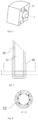
FIG. 1 is a structural cross-sectional view of an experimental device for an ignition mechanism of oblique-injecting jet non-premixed annular combustor according to the present invention; -
FIG. 2 is an axonometric view of oblique-injecting jet annular burner according to the present invention; -
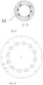
FIG. 3 is a top view and a bottom view of oblique-injecting jet annular burner according to the present invention; -
FIG. 4 is a schematic structural diagram of an outer middle wall of a combustor according to the present invention; -
FIG. 5 is a first schematic structural diagram of an atomizing nozzle of a burner and a fixing seat therefor according to the present invention; -
FIG. 6 is a second schematic structural diagram of an atomizing nozzle of a burner and a fixing seat therefor according to the present invention; -
FIG. 7 is a cross-sectional view of an oblique-injecting swirl nozzle and a schematic view of a swirling channel according to the present invention; -
FIG. 8 is a cross-sectional view taken along A-A inFIG. 7 ; -
FIG. 9 is a cross-sectional view taken along B-B inFIG. 7 ; and -
FIG. 10 is a bottom view of a top flange according to the present invention. - In the figures:
1 - Bottom flange, 2 - Middle flange, 3 - Top flange, 4 - Inner wall of an annular combustor, 5 - Outer lower wall of the annular combustor, 6 - Outer middle wall of the annular combustor, 7 - Outer upper wall of the annular combustor, 8 - Atomizing nozzle fixing seat, 9 - Atomizing nozzle, 10 - Oblique-injecting swirl nozzle, 11 - Middle fastening bolt, 12 - Middle support column, 13 - Honeycomb plate, 14 - Air inlet, 15 - Distribution chamber, 16 - Annular combustor, 17 - Atomizing nozzle fixing hole, 18 - Ignition pin hole, 19 - Acoustic pressure test hole, 20 - Burner bottom fixing hole, 21 - Outer edge fastening bolt hole, 22 - Sealing groove, 23 - Atomized jet outlet, 24 - Atomizing nozzle fixing seat limiting boss, 25 - Atomizing nozzle fixing seat mounting threaded hole, 26 - Quartz glass limiting boss, 27 - Fuel delivery inlet threaded hole, 28 - Atomizing nozzle connecting threaded hole, 29 - Recess of the oblique-injecting swirl nozzle, 30 - Boss of the oblique-injecting swirl nozzle, 31 - Main flow channel, 32 - First swirl channel, 33 - Second swirl channel, 34 - Oblique-injecting swirl nozzle passage hole, 35 - Oblique-injecting swirl nozzle mounting hole. - The technical solutions in the embodiments of the present invention will be clearly and completely described below with reference to the accompanying drawings in the embodiments of the present invention. Obviously, the embodiments described are merely some rather than all of the embodiments of the present invention. On the basis of the embodiments of the present invention, all other embodiments obtained by those of ordinary skill in the art without involving any inventive efforts shall fall within the scope of protection of the present invention.
- Referring to
FIGS. 1 to 10 , the present invention provides a device for research on an ignition mechanism of an oblique-injecting non-premixed annular combustor, the device comprising adistribution chamber 15, anannular combustor 16, and an atomizing jet assembly. Thedistribution chamber 15 comprises atop flange 3. Theannular combustor 16 comprises oblique-injectingswirl nozzles 10, aninner wall 4 of the annular combustor, and an outer wall assembly of the annular combustor. An upper surface of thetop flange 3 is provided with asealing groove 22. Theinner wall 4 of the annular combustor and the outer wall assembly of the annular combustor are mounted in a groove at the top end of thetop flange 3. Theinner wall 4 of the annular combustor and the outer wall assembly of the annular combustor are in a millimeter-scale clearance fit with thetop flange 3. The oblique-injectingswirl nozzles 10 obliquely pass through oblique-injecting swirl nozzle passage holes 34 in thetop flange 3, and are circumferentially uniformly mounted in oblique-injecting swirl nozzle mounting holes 35 in thetop flange 3, and theannular combustor 16 is in communication with thedistribution chamber 15 through the oblique-injectingswirl nozzles 10. - The atomizing jet assembly comprises an
atomizing nozzle 9 and an atomizingnozzle fixing seat 8. A number of rectangular grooves are cut in an outermiddle wall 6 of the annular combustor, they are provided for tight attachment and assemblage with the atomizingnozzle fixing seat 8. A rectangular plane is provided with a threaded hole, so as to be fixedly mounted to the atomizingnozzle fixing seat 8 by means of a bolt. The rectangular plane is provided with a through hole, which allows theatomizing nozzle 9 to pass through and supply atomized fuel into theannular combustor 16. An upper surface and a lower surface of the outermiddle wall 6 of the annular combustor are both provided with bosses, which can be respectively configured to receive and limit an outerupper wall 7 of the annular combustor and to be placed on an outerlower wall 5 of the annular combustor. Each contact mounting clearance is in a millimeter order. This clearance can meet expansion and contraction deformation of a face of the outerupper wall 7 of the annular combustor and a face of the outerlower wall 5 of the annular combustor that is made of quartz glass and a face of the outermiddle wall 6 of the annular combustor that is made of stainless steel. - The atomizing
nozzle fixing seat 8 is provided with four atomizingnozzle fixing holes 17 for fixing the atomizing nozzle fixing seat to the outermiddle wall 6 of the annular combustor after bolts pass through, and is further provided with two oblique threaded holes that are a fuel delivery inlet threadedhole 27 and an atomizing nozzle connecting threadedhole 28, which are respectively configured to mount and connect a fuel delivery pipeline and theatomizing nozzle 9. The fuel delivery inlet threadedhole 27 and the atomizing nozzle connecting threadedhole 28 can adjust a radial included angle between the atomizingnozzle 9 and theannular combustor 16, so as to adjust the structural parameters of an included angle between the atomizingnozzle 9 and the outermiddle wall 6 of the annular combustor. The outerlower wall 5 of the annular combustor is provided with an ignition pin hole 18, and an ignition pin is inserted into theannular combustor 16 from the ignition pin hole 18 to ignite a mixture of air and the atomized fuel. - An
atomizing nozzle 9 fixing support is made of an aluminum alloy with its dead weight lighter than that of stainless steel, and is fixed to the outermiddle wall 6 of the annular combustor by means of four bolts, with an axial displacement being within a maximum limit displacement range, and the deformation after experimental heating being also within the maximum limit deformation range. An acute-angle channel with theannular combustor 16 in a radial direction can meet that theatomizing nozzle 9 and an inlet of the fuel delivery pipeline are in the same axial direction. At this time, an acute angle is formed between an outlet of theatomizing nozzle 9 and an outlet of the outermiddle wall 6 of the annular combustor. Two ends of this channel are hermetically fitted by means of threads to ensure that an outlet of the fuel delivery pipeline and an inlet of theatomizing nozzle 9 are in the same pressure chamber, so that fuel can form mist by means of theatomizing nozzle 9. Further, theatomizing nozzle 9 and the outermiddle wall 6 of the annular combustor may be inverted as a whole, so that an included angle between the atomizingnozzle 9 and the oblique-injectingswirl nozzle 10 can be adjusted, which is an obtuse angle in this case. - The
atomizing nozzle 9 is made of a metal, which can withstand high temperature for several minutes. In addition, the atomizing nozzle has different atomizing cone angles of 30°, 45°, 60° and 80°, and pore diameters of 0.5 m, 1 mm, 1.5 mm, and 2 mm, so that structural parameters of different atomization effects can be adjusted. - The oblique-injecting
swirl nozzle 10 is provided with a central blind hole as amain flow channel 31, and an acute angle is formed between an axis of themain flow channel 31 and a central axis of theannular combustor 16. A side wall of the oblique-injectingswirl nozzle 10 is provided with two channels with tangential circular holes, which are afirst swirl channel 32 and asecond swirl channel 33. Thefirst swirl channel 32 and thesecond swirl channel 33 each are provided with six circular holes. Airflow enter themain flow channel 31 from the channels with tangential circular holes to form swirl flow. An outer wall of the oblique-injectingswirl nozzle 10 is provided with aboss 30 of the oblique-injecting swirl nozzle and arecess 29 of the oblique-injecting swirl nozzle, which are respectively configured to be in close fit with the top flange and to fixedly mount the oblique-injectingswirl nozzle 10 on thetop flange 3 by means of bolts. The oblique-injectingswirl nozzle 10 can effectively enhance the turbulence of air, improve the effect of mixing with the atomized fuel, and further provide circumferential angular momentum for the airflow entering theannular combustor 16 to reduce an aerodynamic loss. Further, the uniformity of a velocity field and a temperature field at an outlet of theannular combustor 16 is improved. - The
distribution chamber 15 further comprises amiddle flange 2, abottom flange 1, and amiddle support column 12. Thebottom flange 1, themiddle flange 2, and thetop flange 3 are bolted with each other by means of peripheral fastening bolt holes 21, and form a sealeddistribution chamber 15 together with themiddle support column 12 and amiddle fastening bolt 11. An upper surface of themiddle flange 2 is provided with a sealinggroove 22 for receiving a sealing ring, and is sealed by being pressed against thetop flange 3. - The
middle support column 12 is provided in the centre with a through hole for allowing themiddle fastening bolt 11 to pass through, an upper surface thereof is provided with a sealinggroove 22 for receiving a sealing ring and is sealed by being pressed against thetop flange 3, and a lower surface thereof is provided with a boss for limiting ahoneycomb plate 13. - An upper surface of the lower flange is provided with an inner and an
outer sealing groove 22 for receiving sealing rings, and seals thedistribution chamber 15 by contact with themiddle support column 12 and themiddle flange 2, and the lower flange is provided in the centre with a through hole for allowing the bolt to pass through, so as to be fixedly connected to thetop flange 3 and themiddle support column 12. A bottom surface of the lower flange is provided with a number of circumferentially symmetrically and uniformly distributed threaded holes, and the threaded holes areair inlets 14. This enables a pressure environment in thedistribution chamber 15 to maintain a certain symmetry and uniformity, and the pressure environment causes the mixed gas to enter each oblique-injectingswirl nozzle 10 at a relatively uniform flow rate, which facilitates the realization of a similarity in flow and combustion between the nozzles. A lower surface of the lower flange is internally chamfered to strengthen the structural strength of the bottom of thedistribution chamber 15, and an outer edge of the lower surface is provided with a burnerbottom fixing hole 20 for being fixedly mounted to an optical platform. - The
bottom flange 1 bears dozens of kilograms of load including the dead weight, with an integral structure being of a thick-walled design to ensure strength and rigidity, and is further mounted in a fitting manner on an experimental platform with sufficient strength, rigidity and stability to meet requirements for loading of the entire device. - The
distribution chamber 15 further comprises ahoneycomb plate 13, themiddle flange 2 passes through the centre of thehoneycomb plate 13, and thehoneycomb plate 13 is mounted at a bottom end of the middle flange. A number of small holes are uniformly distributed in thehoneycomb plate 13. After airflow passes through the holes, the turbulence and vortex can be weakened, and the airflow uniformity in thedistribution chamber 15 is improved. The staggered arrangement of a plurality of layers ofhoneycomb plates 13 can further improve this effect. - A side wall of the
middle flange 2 is provided with acoustic pressure test holes 19. Plugs or acoustic measuring plugs are mounted in the acoustic pressure test holes 19 of the side wall and can output pressure signals of thedistribution chamber 15 to a data acquisition system, so as to provide experimental data for research on the atomization ignition mechanism of the oblique-injecting non-premixedannular combustor 16. - The outer wall assembly of the annular combustor comprises an outer
lower wall 5 of the annular combustor, an outermiddle wall 6 of the annular combustor, and an outerupper wall 7 of the annular combustor. The outerlower wall 5 of the annular combustor is mounted at the bottom end of the outermiddle wall 6 of the annular combustor, the outerupper wall 7 of the annular combustor is mounted at the top end of the outermiddle wall 6 of the annular combustor, the outerlower wall 5 of the annular combustor is mounted on thetop flange 3, the atomizing jet assembly is mounted on the outermiddle wall 6 of the annular combustor, and the ignition pin hole 18 is formed in the outerlower wall 5 of the annular combustor. - Transparent thick-walled cylinders made of quartz are used as the outer
upper wall 7 of the annular combustor and the outerlower wall 5 of the annular combustor, and have the following characteristics: the transparent thick-walled cylinders are resistant to high temperature, have a small thermal expansion rate, and can effectively adapt to a high temperature environment; a quartz tube is thick enough to ensure the strength, and the pressure resistance exceeds 10 atm within a safe range; and the transparent quartz tube can provide a window for optical measurement and data acquisition. - The outer
middle wall 6 of the annular combustor is made of stainless steel. A plurality of groups of atomizedjet outlets 23, atomizing nozzle fixingseat limiting bosses 24 and atomizing nozzle fixing seat mounting threadedholes 25 for mounting theatomizing nozzle 9 and the atomizingnozzle fixing seat 8 are circumferentially and uniformly distributed on the outermiddle wall 6 the annular combustor. An inner side of the outermiddle wall 6 of the annular combustor is further provided with a quartzglass limiting boss 26. The outer middle wall of the annular combustor is deformed radially outwardly due to heating during an experiment, the deformation has little impact on the experiment in terms of errors, and the deformation is smaller than the thermal deformation of the outerupper wall 7 of the annular combustor and the outerlower wall 5 of the annular combustor that is made of quartz, which can ensure that an outer wall of theannular combustor 16 is in a safe experimental environment. - The heights of the outer
upper wall 7 of the annular combustor and the outerlower wall 5 of the annular combustor can be adjusted, so as to conduct experimental research at different atomization heights from an obliquely-injected jet outlet. The outerlower wall 5 of the annular combustor is configured to have different heights to adjust a distance between the atomizingnozzle 9 and an outlet of theannular combustor 16, so as to explore changes of flow field characteristics, ignition performance and flame propagation process as atomized fuel is injected at different outlet positions. - Fastening bolts in a burner are all made of alloy steel, middle fastening bolts have a strength of Class 12.9, and by cooperation with outer edge fastening bolts with a strength of Class 10.9, the entire burner is ensured to be tightly and hermetically fitted, which meets safety requirements under high pressure inside the
distribution chamber 15. - The experimental device according to the present invention can be effectively applied to research on the mechanism of flow field characteristics, ignition performance and flame propagation of the oblique-injecting jet non-premixed
annular combustor 16, especially the research related to fuel atomization close to theannular combustor 16 of an actual engine. - In step S1, a
bottom flange 1 is fixed to an optical platform, an air supply pipeline is connected to airinlets 14 after passing through a middle hole of the optical platform, then ahoneycomb plate 13 and amiddle support column 12 are coaxially placed on thebottom flange 1, a sealing ring is placed in a sealinggroove 22, oblique-injectingswirl nozzles 10 are mounted to atop flange 3, then the integrated structure is connected to amiddle flange 2 by means of bolts, and then the connected integrated structure is connected to thebottom flange 1 by means of outer edge bolts andmiddle fastening bolts 11, to complete the assembly of adistribution chamber 15. - In step S2, an
inner wall 4 of an annular combustor and an outerlower wall 5 of the annular combustor are placed on thetop flange 3 and limited by bosses, then a fuel delivery pipeline is connected to an atomizingnozzle fixing seat 8, anatomizing nozzle 9 is mounted on the atomizingnozzle fixing seat 8, the integrated structure is fixed to an outermiddle wall 6 of the annular combustor, the outermiddle wall 6 of the annular combustor is placed on an outerlower wall 5 of the annular combustor, finally an outerupper wall 7 of the annular combustor is placed on the outermiddle wall 6 of the annular combustor, and limiting between each other is implemented by means of bosses, so as to complete the assembly of theannular combustor 16. - In step S3, circumferentially symmetric acoustic pressure test holes 19 in an outer wall of the
middle flange 2 are connected to acoustic pressure signal collectors to complete acoustic pressure collection. - The embodiments in the description are described in a progressive manner, each embodiment focuses on the differences from other embodiments, and the same and similar parts of the various embodiments can be referred to each other. Since the device disclosed in an embodiment corresponds to the method disclosed in an embodiment, the description is relatively simple, and for the relevant part, reference may be made to the description of the method.
- The above description of the disclosed embodiments enables those skilled in the art to achieve or use the present invention. Various modifications to these embodiments will be apparent to those skilled in the art. The general principles defined herein may be implemented in other embodiments without departing from the spirit or scope of the present invention. Therefore, the present invention will not be limited to the embodiments shown herein, but should conform to the widest scope consistent with the principles and novel features disclosed herein.
Claims (9)
- A device for research on an ignition mechanism of an oblique-injecting non-premixed annular combustor, characterized by comprising: a distribution chamber, an annular combustor, and an atomizing jet assembly, wherein the distribution chamber comprises a top flange, and the annular combustor comprises oblique-injecting swirl nozzles, an inner wall of the combustor, and an outer wall assembly of the combustor; and the inner wall of the combustor and the outer wall assembly of the combustor are mounted at a top end of the top flange; each of the oblique-injecting swirl nozzles obliquely passes through the top flange and is mounted on the top flange, and the annular combustor is in communication with the distribution chamber through the oblique-injecting swirl nozzle; the atomizing jet assembly comprises an atomizing nozzle and an atomizing nozzle fixing seat, wherein the atomizing nozzle fixing seat is provided with a fuel delivery inlet threaded hole and an atomizing nozzle connecting threaded hole, the atomizing nozzle fixing seat is in a threaded connection with a side wall of an outer middle wall of the combustor, the atomizing nozzle is mounted in the atomizing nozzle connecting threaded hole, and the fuel delivery inlet threaded hole is connected to a fuel delivery pipeline; and a side wall of the outer wall assembly of the combustor is provided with an ignition pin hole.
- The device for research on an ignition mechanism of an oblique-injecting non-premixed annular combustor according to claim 1, characterized in that angles of the fuel delivery inlet threaded hole and the atomizing nozzle connecting threaded hole are adjustable, so as to conduct experimental research at different included angles formed between an atomized jet and an obliquely-injected air jet.
- The device for research on an ignition mechanism of an oblique-injecting non-premixed annular combustor according to claim 1, characterized in that the oblique-injecting swirl nozzle is provided with a first swirl channel, a second swirl channel, and a main flow channel.
- The device for research on an ignition mechanism of an oblique-injecting non-premixed annular combustor according to claim 1, characterized in that the distribution chamber further comprises a middle flange, a bottom flange, and a middle support column, wherein the middle flange is in a threaded connection with a top end of the bottom flange, the top flange is in a threaded connection with a top end of the middle flange, the middle support column is located on a central axis and is in a threaded connection between the top flange and the bottom flange, and the bottom flange is provided with air inlets.
- The device for research on an ignition mechanism of an oblique-injecting non-premixed annular combustor according to claim 4, characterized in that the air inlets are circumferentially symmetrically distributed in the bottom flange.
- The device for research on an ignition mechanism of an oblique-injecting non-premixed annular combustor according to claim 4, characterized in that the distribution chamber further comprises a honeycomb plate, the middle flange passes through the centre of the honeycomb plate, and the honeycomb plate is mounted at a bottom end of the middle flange.
- The device for research on an ignition mechanism of an oblique-injecting non-premixed annular combustor according to claim 4, characterized in that a side wall of the middle flange is provided with an acoustic pressure test hole.
- The device for research on an ignition mechanism of an oblique-injecting non-premixed annular combustor according to claim 1, characterized in that the outer wall assembly of the combustor comprises an outer lower wall of the combustor, the outer middle wall of the combustor, and an outer upper wall of the combustor, wherein the outer lower wall of the combustor is mounted at a bottom end of the outer middle wall of the combustor, the outer upper wall of the combustor is mounted at a top end of the outer middle wall of the combustor, the outer lower wall of the combustor is mounted on the top flange, the atomizing jet assembly is mounted on the outer middle wall of the combustor, and the ignition pin hole is formed in the outer lower wall of the combustor.
- The device for research on an ignition mechanism of an oblique-injecting non-premixed annular combustor according to claim 8, characterized in that the outer upper wall of the combustor and the outer lower wall of the combustor have adjustable heights, so as to conduct experimental research at different atomization heights from an obliquely-injected jet outlet.
Applications Claiming Priority (2)
| Application Number | Priority Date | Filing Date | Title |
|---|---|---|---|
| CN202210254085.0A CN114508769B (en) | 2022-03-15 | 2022-03-15 | Ignition mechanism research device of inclined-jet non-premixed annular combustion chamber |
| PCT/CN2022/133204 WO2023173792A1 (en) | 2022-03-15 | 2022-11-21 | Oblique spraying non-premix annular combustion chamber ignition mechanism research device |
Publications (4)
| Publication Number | Publication Date |
|---|---|
| EP4279813A1 true EP4279813A1 (en) | 2023-11-22 |
| EP4279813A4 EP4279813A4 (en) | 2024-02-28 |
| EP4279813C0 EP4279813C0 (en) | 2025-01-15 |
| EP4279813B1 EP4279813B1 (en) | 2025-01-15 |
Family
ID=81553758
Family Applications (1)
| Application Number | Title | Priority Date | Filing Date |
|---|---|---|---|
| EP22847398.9A Active EP4279813B1 (en) | 2022-03-15 | 2022-11-21 | Device for research on an ignition mechanism of an oblique spraying non-premixed annular combustion chamber |
Country Status (3)
| Country | Link |
|---|---|
| EP (1) | EP4279813B1 (en) |
| CN (1) | CN114508769B (en) |
| WO (1) | WO2023173792A1 (en) |
Families Citing this family (4)
| Publication number | Priority date | Publication date | Assignee | Title |
|---|---|---|---|---|
| CN114508769B (en) * | 2022-03-15 | 2022-11-25 | 浙江大学 | Ignition mechanism research device of inclined-jet non-premixed annular combustion chamber |
| CN115789703A (en) * | 2022-12-02 | 2023-03-14 | 苏州达储能源科技有限公司 | Device capable of adjusting jet flow angle to control thermoacoustic vibration and NOx emission |
| CN119555387B (en) * | 2024-10-31 | 2025-11-04 | 四川泛华航空仪表电器有限公司 | A method and apparatus for testing the ignition voltage of an ignition electrode in an aircraft engine. |
| CN120402932B (en) * | 2025-07-01 | 2025-09-05 | 中国航发燃气轮机有限公司 | Combustion chamber and nozzle thereof |
Family Cites Families (12)
| Publication number | Priority date | Publication date | Assignee | Title |
|---|---|---|---|---|
| GB657938A (en) * | 1948-11-06 | 1951-09-26 | Oerlikon Maschf | Device for atomising fluid fuel by means of air in combustion chambers |
| GB721750A (en) * | 1951-07-24 | 1955-01-12 | Benjamin Normington | Improvements in or relating to oil burners for furnaces and the like |
| US4936090A (en) * | 1988-07-15 | 1990-06-26 | Sundstrand Corporation | Assuring reliable starting of turbine engines |
| JP4274996B2 (en) * | 2004-04-27 | 2009-06-10 | 三菱重工業株式会社 | Gas turbine combustor |
| CN100443806C (en) * | 2006-05-16 | 2008-12-17 | 北京航空航天大学 | tangential trapped vortex combustor |
| JP4939179B2 (en) * | 2006-11-17 | 2012-05-23 | 財団法人電力中央研究所 | Gas turbine combustor and operation method thereof |
| CN107014618B (en) * | 2017-03-29 | 2019-03-29 | 浙江大学 | An experimental research device for the coupling mechanism of combustion chamber and turbine |
| CN207019906U (en) * | 2017-08-04 | 2018-02-16 | 浙江大学 | A kind of device for measuring turbulent burner thermoacoustic transitive relation |
| CN107327872A (en) * | 2017-08-04 | 2017-11-07 | 浙江大学 | A kind of oblique spray ring stream toroidal combustion chamber |
| CN211822364U (en) * | 2020-01-08 | 2020-10-30 | 福建鼎元热能技术有限公司 | Environment-friendly combustor |
| CN112856413B (en) * | 2021-01-15 | 2022-03-18 | 西安交通大学 | Adjustable hydrogen injection/secondary air inlet burner and combustion method |
| CN114508769B (en) * | 2022-03-15 | 2022-11-25 | 浙江大学 | Ignition mechanism research device of inclined-jet non-premixed annular combustion chamber |
-
2022
- 2022-03-15 CN CN202210254085.0A patent/CN114508769B/en active Active
- 2022-11-21 EP EP22847398.9A patent/EP4279813B1/en active Active
- 2022-11-21 WO PCT/CN2022/133204 patent/WO2023173792A1/en not_active Ceased
Also Published As
| Publication number | Publication date |
|---|---|
| CN114508769B (en) | 2022-11-25 |
| EP4279813C0 (en) | 2025-01-15 |
| WO2023173792A1 (en) | 2023-09-21 |
| CN114508769A (en) | 2022-05-17 |
| EP4279813A4 (en) | 2024-02-28 |
| EP4279813B1 (en) | 2025-01-15 |
Similar Documents
| Publication | Publication Date | Title |
|---|---|---|
| EP4279813B1 (en) | Device for research on an ignition mechanism of an oblique spraying non-premixed annular combustion chamber | |
| US11255543B2 (en) | Dilution structure for gas turbine engine combustor | |
| US5671597A (en) | Low nox fuel nozzle assembly | |
| US7878000B2 (en) | Pilot fuel injector for mixer assembly of a high pressure gas turbine engine | |
| CN116293812B (en) | Fuel nozzle and swirler | |
| US20200041127A1 (en) | Dilution Structure for Gas Turbine Engine Combustor | |
| US11598526B2 (en) | Combustor swirl vane apparatus | |
| US5241818A (en) | Fuel injector for a gas turbine engine | |
| US11326521B2 (en) | Methods of igniting liquid fuel in a turbomachine | |
| US11802693B2 (en) | Combustor swirl vane apparatus | |
| EP0564170A1 (en) | Segmented centerbody for a double annular combustor | |
| US12422140B2 (en) | Combustor deflector assembly | |
| CN207334780U (en) | Oblique spray ring stream toroidal combustion chamber | |
| US11828466B2 (en) | Combustor swirler to CMC dome attachment | |
| CN107327872A (en) | A kind of oblique spray ring stream toroidal combustion chamber | |
| EP3441675A1 (en) | Volute combustor for gas turbine engine | |
| EP4123224B1 (en) | Cartridge tip for turbomachine combustor | |
| CN216143778U (en) | Combustor and premixed air inlet type backflow annular combustion chamber | |
| CN116398905A (en) | Backflow combustion chamber adopting visible optical observation structure | |
| US11774099B2 (en) | Gas turbine fuel nozzle tip comprising an impingement wall | |
| CA2597846A1 (en) | Pilot fuel injector for mixer assembly of a high pressure gas turbine engine | |
| US20220372915A1 (en) | Passive fuel coupled dynamic mitigation device | |
| US20250189130A1 (en) | Gas turbine engine and combustor therefor | |
| US11815267B2 (en) | Combustor liner having cooling dispersing member for localized liner cooling |
Legal Events
| Date | Code | Title | Description |
|---|---|---|---|
| STAA | Information on the status of an ep patent application or granted ep patent |
Free format text: STATUS: UNKNOWN |
|
| STAA | Information on the status of an ep patent application or granted ep patent |
Free format text: STATUS: THE INTERNATIONAL PUBLICATION HAS BEEN MADE |
|
| PUAI | Public reference made under article 153(3) epc to a published international application that has entered the european phase |
Free format text: ORIGINAL CODE: 0009012 |
|
| STAA | Information on the status of an ep patent application or granted ep patent |
Free format text: STATUS: REQUEST FOR EXAMINATION WAS MADE |
|
| 17P | Request for examination filed |
Effective date: 20230207 |
|
| AK | Designated contracting states |
Kind code of ref document: A1 Designated state(s): AL AT BE BG CH CY CZ DE DK EE ES FI FR GB GR HR HU IE IS IT LI LT LU LV MC ME MK MT NL NO PL PT RO RS SE SI SK SM TR |
|
| STAA | Information on the status of an ep patent application or granted ep patent |
Free format text: STATUS: EXAMINATION IS IN PROGRESS |
|
| RIC1 | Information provided on ipc code assigned before grant |
Ipc: F23R 3/28 20060101AFI20240118BHEP |
|
| A4 | Supplementary search report drawn up and despatched |
Effective date: 20240125 |
|
| 17Q | First examination report despatched |
Effective date: 20240213 |
|
| GRAP | Despatch of communication of intention to grant a patent |
Free format text: ORIGINAL CODE: EPIDOSNIGR1 |
|
| STAA | Information on the status of an ep patent application or granted ep patent |
Free format text: STATUS: GRANT OF PATENT IS INTENDED |
|
| INTG | Intention to grant announced |
Effective date: 20240912 |
|
| GRAS | Grant fee paid |
Free format text: ORIGINAL CODE: EPIDOSNIGR3 |
|
| GRAA | (expected) grant |
Free format text: ORIGINAL CODE: 0009210 |
|
| STAA | Information on the status of an ep patent application or granted ep patent |
Free format text: STATUS: THE PATENT HAS BEEN GRANTED |
|
| DAV | Request for validation of the european patent (deleted) | ||
| DAX | Request for extension of the european patent (deleted) | ||
| AK | Designated contracting states |
Kind code of ref document: B1 Designated state(s): AL AT BE BG CH CY CZ DE DK EE ES FI FR GB GR HR HU IE IS IT LI LT LU LV MC ME MK MT NL NO PL PT RO RS SE SI SK SM TR |
|
| REG | Reference to a national code |
Ref country code: CH Ref legal event code: EP Ref country code: GB Ref legal event code: FG4D |
|
| REG | Reference to a national code |
Ref country code: DE Ref legal event code: R096 Ref document number: 602022009668 Country of ref document: DE |
|
| REG | Reference to a national code |
Ref country code: IE Ref legal event code: FG4D |
|
| U01 | Request for unitary effect filed |
Effective date: 20250214 |
|
| U07 | Unitary effect registered |
Designated state(s): AT BE BG DE DK EE FI FR IT LT LU LV MT NL PT RO SE SI Effective date: 20250220 |
|
| PG25 | Lapsed in a contracting state [announced via postgrant information from national office to epo] |
Ref country code: RS Free format text: LAPSE BECAUSE OF FAILURE TO SUBMIT A TRANSLATION OF THE DESCRIPTION OR TO PAY THE FEE WITHIN THE PRESCRIBED TIME-LIMIT Effective date: 20250415 |
|
| PG25 | Lapsed in a contracting state [announced via postgrant information from national office to epo] |
Ref country code: PL Free format text: LAPSE BECAUSE OF FAILURE TO SUBMIT A TRANSLATION OF THE DESCRIPTION OR TO PAY THE FEE WITHIN THE PRESCRIBED TIME-LIMIT Effective date: 20250115 |
|
| PG25 | Lapsed in a contracting state [announced via postgrant information from national office to epo] |
Ref country code: ES Free format text: LAPSE BECAUSE OF FAILURE TO SUBMIT A TRANSLATION OF THE DESCRIPTION OR TO PAY THE FEE WITHIN THE PRESCRIBED TIME-LIMIT Effective date: 20250115 |
|
| PG25 | Lapsed in a contracting state [announced via postgrant information from national office to epo] |
Ref country code: IS Free format text: LAPSE BECAUSE OF FAILURE TO SUBMIT A TRANSLATION OF THE DESCRIPTION OR TO PAY THE FEE WITHIN THE PRESCRIBED TIME-LIMIT Effective date: 20250515 Ref country code: NO Free format text: LAPSE BECAUSE OF FAILURE TO SUBMIT A TRANSLATION OF THE DESCRIPTION OR TO PAY THE FEE WITHIN THE PRESCRIBED TIME-LIMIT Effective date: 20250415 |
|
| PG25 | Lapsed in a contracting state [announced via postgrant information from national office to epo] |
Ref country code: HR Free format text: LAPSE BECAUSE OF FAILURE TO SUBMIT A TRANSLATION OF THE DESCRIPTION OR TO PAY THE FEE WITHIN THE PRESCRIBED TIME-LIMIT Effective date: 20250115 |
|
| PG25 | Lapsed in a contracting state [announced via postgrant information from national office to epo] |
Ref country code: GR Free format text: LAPSE BECAUSE OF FAILURE TO SUBMIT A TRANSLATION OF THE DESCRIPTION OR TO PAY THE FEE WITHIN THE PRESCRIBED TIME-LIMIT Effective date: 20250416 |
|
| PG25 | Lapsed in a contracting state [announced via postgrant information from national office to epo] |
Ref country code: SM Free format text: LAPSE BECAUSE OF FAILURE TO SUBMIT A TRANSLATION OF THE DESCRIPTION OR TO PAY THE FEE WITHIN THE PRESCRIBED TIME-LIMIT Effective date: 20250115 |
|
| PG25 | Lapsed in a contracting state [announced via postgrant information from national office to epo] |
Ref country code: CZ Free format text: LAPSE BECAUSE OF FAILURE TO SUBMIT A TRANSLATION OF THE DESCRIPTION OR TO PAY THE FEE WITHIN THE PRESCRIBED TIME-LIMIT Effective date: 20250115 |
|
| PG25 | Lapsed in a contracting state [announced via postgrant information from national office to epo] |
Ref country code: SK Free format text: LAPSE BECAUSE OF FAILURE TO SUBMIT A TRANSLATION OF THE DESCRIPTION OR TO PAY THE FEE WITHIN THE PRESCRIBED TIME-LIMIT Effective date: 20250115 |
|
| U1N | Appointed representative for the unitary patent procedure changed after the registration of the unitary effect |
Representative=s name: SANTARELLI; FR |
|
| PLBE | No opposition filed within time limit |
Free format text: ORIGINAL CODE: 0009261 |
|
| STAA | Information on the status of an ep patent application or granted ep patent |
Free format text: STATUS: NO OPPOSITION FILED WITHIN TIME LIMIT |
|
| REG | Reference to a national code |
Ref country code: CH Ref legal event code: L10 Free format text: ST27 STATUS EVENT CODE: U-0-0-L10-L00 (AS PROVIDED BY THE NATIONAL OFFICE) Effective date: 20251126 |
|
| 26N | No opposition filed |
Effective date: 20251016 |
|
| U20 | Renewal fee for the european patent with unitary effect paid |
Year of fee payment: 4 Effective date: 20251127 |
|
| REG | Reference to a national code |
Ref country code: CH Ref legal event code: H13 Free format text: ST27 STATUS EVENT CODE: U-0-0-H10-H13 (AS PROVIDED BY THE NATIONAL OFFICE) Effective date: 20260623 |
|
| PG25 | Lapsed in a contracting state [announced via postgrant information from national office to epo] |
Ref country code: MC Free format text: LAPSE BECAUSE OF FAILURE TO SUBMIT A TRANSLATION OF THE DESCRIPTION OR TO PAY THE FEE WITHIN THE PRESCRIBED TIME-LIMIT Effective date: 20250115 |
|
| PG25 | Lapsed in a contracting state [announced via postgrant information from national office to epo] |
Ref country code: CH Free format text: LAPSE BECAUSE OF NON-PAYMENT OF DUE FEES Effective date: 20251130 |