EP4279812A1 - Fuel oil injector with shielding air supply - Google Patents
Fuel oil injector with shielding air supply Download PDFInfo
- Publication number
- EP4279812A1 EP4279812A1 EP22425022.5A EP22425022A EP4279812A1 EP 4279812 A1 EP4279812 A1 EP 4279812A1 EP 22425022 A EP22425022 A EP 22425022A EP 4279812 A1 EP4279812 A1 EP 4279812A1
- Authority
- EP
- European Patent Office
- Prior art keywords
- fuel oil
- tubular body
- air
- convergent
- duct
- Prior art date
- Legal status (The legal status is an assumption and is not a legal conclusion. Google has not performed a legal analysis and makes no representation as to the accuracy of the status listed.)
- Granted
Links
Images

Classifications
-
- F—MECHANICAL ENGINEERING; LIGHTING; HEATING; WEAPONS; BLASTING
- F02—COMBUSTION ENGINES; HOT-GAS OR COMBUSTION-PRODUCT ENGINE PLANTS
- F02C—GAS-TURBINE PLANTS; AIR INTAKES FOR JET-PROPULSION PLANTS; CONTROLLING FUEL SUPPLY IN AIR-BREATHING JET-PROPULSION PLANTS
- F02C7/00—Features, components parts, details or accessories, not provided for in, or of interest apart form groups F02C1/00 - F02C6/00; Air intakes for jet-propulsion plants
- F02C7/22—Fuel supply systems
-
- F—MECHANICAL ENGINEERING; LIGHTING; HEATING; WEAPONS; BLASTING
- F23—COMBUSTION APPARATUS; COMBUSTION PROCESSES
- F23R—GENERATING COMBUSTION PRODUCTS OF HIGH PRESSURE OR HIGH VELOCITY, e.g. GAS-TURBINE COMBUSTION CHAMBERS
- F23R3/00—Continuous combustion chambers using liquid or gaseous fuel
- F23R3/28—Continuous combustion chambers using liquid or gaseous fuel characterised by the fuel supply
- F23R3/283—Attaching or cooling of fuel injecting means including supports for fuel injectors, stems, or lances
-
- F—MECHANICAL ENGINEERING; LIGHTING; HEATING; WEAPONS; BLASTING
- F23—COMBUSTION APPARATUS; COMBUSTION PROCESSES
- F23D—BURNERS
- F23D11/00—Burners using a direct spraying action of liquid droplets or vaporised liquid into the combustion space
- F23D11/10—Burners using a direct spraying action of liquid droplets or vaporised liquid into the combustion space the spraying being induced by a gaseous medium, e.g. water vapour
- F23D11/108—Burners using a direct spraying action of liquid droplets or vaporised liquid into the combustion space the spraying being induced by a gaseous medium, e.g. water vapour medium and fuel intersecting downstream of the burner outlet
-
- F—MECHANICAL ENGINEERING; LIGHTING; HEATING; WEAPONS; BLASTING
- F23—COMBUSTION APPARATUS; COMBUSTION PROCESSES
- F23L—SUPPLYING AIR OR NON-COMBUSTIBLE LIQUIDS OR GASES TO COMBUSTION APPARATUS IN GENERAL ; VALVES OR DAMPERS SPECIALLY ADAPTED FOR CONTROLLING AIR SUPPLY OR DRAUGHT IN COMBUSTION APPARATUS; INDUCING DRAUGHT IN COMBUSTION APPARATUS; TOPS FOR CHIMNEYS OR VENTILATING SHAFTS; TERMINALS FOR FLUES
- F23L7/00—Supplying non-combustible liquids or gases, other than air, to the fire, e.g. oxygen, steam
- F23L7/002—Supplying water
-
- F—MECHANICAL ENGINEERING; LIGHTING; HEATING; WEAPONS; BLASTING
- F23—COMBUSTION APPARATUS; COMBUSTION PROCESSES
- F23L—SUPPLYING AIR OR NON-COMBUSTIBLE LIQUIDS OR GASES TO COMBUSTION APPARATUS IN GENERAL ; VALVES OR DAMPERS SPECIALLY ADAPTED FOR CONTROLLING AIR SUPPLY OR DRAUGHT IN COMBUSTION APPARATUS; INDUCING DRAUGHT IN COMBUSTION APPARATUS; TOPS FOR CHIMNEYS OR VENTILATING SHAFTS; TERMINALS FOR FLUES
- F23L2900/00—Special arrangements for supplying or treating air or oxidant for combustion; Injecting inert gas, water or steam into the combustion chamber
- F23L2900/07008—Injection of water into the combustion chamber
Definitions
- the present invention relates to a fuel oil injector with shielding air supply.
- gas turbine engines are required to run on fuel oil at any load condition, including low load and even start-up, besides base load. Not only increase of firing temperature is sought to improve efficiency at high load, but also compliant operation at low load in therefore expected.
- gas turbine engines running exclusively on fuel oil are frequently used as back-up systems for renewable energy market. As intervention of the back-up systems is quite rare, a relatively limited stock of fuel oil is sufficient to avoid discontinuing service and no connection to gas supply is provided, as it would be unnecessarily costly.
- Fuel oil feed is accomplished through lance injector, which however are normally designed for high load and may not prove satisfactory at low load conditions. Therefore, also fuel oil injection has to be carefully designed with a twofold view of optimizing performance and avoiding coking buildup, which may reduce efficiency and even component lifetime.
- Known solutions include lance injectors with concentric feed lines and nozzles dedicated to delivery of fuel oil, water and sometimes fuel gas and/or shielding air, possibly.
- the innermost line is normally dedicated to the supply (and return, if the case be) of fuel oil, which is delivered through injection nozzles to form a hollow cone and improve combustion.
- Water may be sprayed around the fuel oil cone, generally for the purpose of cutting NOx emissions.
- Shielding air if present, is injected in parallel flow with the fuel oil and surrounds the water layer. Shielding air thus forms a protective cold layer that delays heating up of the fuel oil and slows down reaction kinetics.
- shielding air may help purge away fuel oil droplets close to the fuel oil nozzle and prevent coking build up.
- a lance injector for a gas turbine engine comprising:
- the first tubular body separates the fuel oil supply duct and the shielding air duct. No additional fluid layers are thus interposed between the delivered fuel oil flow and the shielding air flow, which therefore interact with each other.
- the interaction of the shielding air flow and of delivered fuel oil flow the has several beneficial effects on combustion.
- the shielding air flow improves mixing of fuel and air and helps break the fuel oil stream into small droplets. In this manner, combustion is more efficient and oxidation is improved, thus leading to a reduction in emissions of carbon monoxide.
- having the shielding air directed towards the centerline of the lance injector promotes interaction and gives additional degrees of freedom in shaping the resulting fuel oil cone spray angle and control of flame position. As a result, combustion dynamics and operation of the burners are remarkably improved.
- shielding air acts as a barrier and protects the fuel oil supply system from hot combustion air recirculation.
- Separate additional measures, such as blocking or sealing air to purge the fuel oil supply duct, are not required.
- a direction of an airflow velocity at the air outlet intersects the delivered fuel oil flow pattern and preferably intersects the central axis.
- the air outlet has an annular convergent shape.
- the annular convergent shape of the air outlet allows to achieve the desired direction and exit angle of the shielding air and to optimize interaction with the resulting fuel oil cone spray.
- the terminal member comprises a hollow first convergent body, connected to the first tubular body and forming a fuel delivery chamber fluidly coupled to the fuel oil supply duct and to the fuel oil nozzle and wherein the fuel oil nozzle is formed in the first convergent body of the terminal member.
- the terminal member comprises a hollow second convergent body, connected to the second tubular body, and wherein the shielding air duct has a convergent section delimited by the body internally and by the second convergent body externally.
- the shielding air is kept separated from the fuel oil flow only by the first convergent body, without any other fluid layers in between.
- the first convergent body has a frustoconical end portion and an injection end of the second convergent body has a convergent frustoconical opening and wherein the air outlet is defined by the frustoconical end portion internally and by the frustoconical opening externally.
- the geometry of the frustoconical end portion and of the frustoconical opening precisely determines the features of the air outlet and the action of the shielding air flow on the cone of the delivered fuel oil flow.
- the first convergent body has a frustoconical intermediate portion between the first tubular body and the frustoconical end portion and wherein an annular step is defined between the frustoconical intermediate portion and the frustoconical end portion in a plane perpendicular to the central axis.
- the injection end of the second convergent body has a cylindrical shape and defines an air plenum around the frustoconical end portion of the first convergent body, between the convergent section of the shielding air duct and the air outlet.
- the air plenum around the around the frustoconical end portion of the first convergent body allows to equalize the shielding air flow before ejection, so that the effect on the delivered fuel oil flow may be accurately determined.
- the supply duct arrangement comprises an outer tubular body extending coaxially around the first tubular body and the second tubular body, wherein a water supply duct is delimited by the second tubular body internally and by the outer tubular body externally, wherein the terminal member has a water outlet coupled to the water supply duct and configured to deliver a water flow around the delivered fuel oil flow.
- the terminal member comprises an outer convergent body extending around the second convergent body and coupled to the water supply duct.
- the water flow may be used to improve control of temperature combustion and pollutant emissions, in particular NOx.
- spraying the water layer does not affect interaction of shielding air and fuel oil.
- the combined action with the shielding air flow reduces the requirements in terms of water supply.
- the supply duct arrangement comprises an inner tubular body, extending concentrically inside the first tubular body, wherein a fuel oil return duct is defined inside the inner tubular body and is coupled to the fuel delivery chamber and wherein the terminal member has passages coupling the fuel oil supply duct and the fuel oil return duct upstream of the fuel delivery chamber.
- a gas turbine engine comprising at least one fuel oil injector as defined above, a fuel oil supply system coupled to the fuel oil supply duct and an air source coupled to the shielding air duct.
- the gas turbine engine comprises an air control valve for each of the at least one fuel oil injector, the air control valve being configured to set air supply to the shielding air duct of the respective fuel oil injector.
- the air supply to the shielding air duct and therefore the shielding air flow of the lance injectors may be thus adjusted in accordance to circumstances, e.g. to optimize or possibly restore combustion conditions, if changes intervenes during the lifetime of the gas turbine engine.
- the gas turbine engine comprises a first group of lance injectors, having the respective air control valves set to allow a first shielding air flow to the respective shielding air ducts, and a second group of lance injectors, having the respective air control valves set to allow a second shielding air flow to the respective shielding air ducts, the second shielding air flow being different from the first shielding air flow.
- Different settings of the lance injectors in the first group and in the second group allow to establish asymmetries in combustion conditions of different burners. Such asymmetries are effective in mitigating pulsations with rotational modes.
- the gas turbine engine comprises a controller and a sensors configured to detect operating quantities of the gas turbine engine, wherein at least one air control valve is an adjustable control valve and the controller is configured to adjust the at least one air control valve based on a response of the sensors.
- the shielding air flow may be dynamically adjusted during operation of the gas turbine engine by a feedback action in response to changing operating condition, for example because of ageing or varying pulsation regimes.
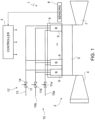
- number 1 defines a gasturbine plant as a whole comprising a gas turbine engine 2 and a controller 3.
- the gas turbine engine 2 in turn, comprises a compressor 4, a combustor assembly 5 and an expansion section or turbine 7. Moreover, sensors 8 are arranged and configured to sense operating quantities of the gas turbine engine 2 and to send measurement signals SM to the controller 3.
- the compressor 4 feeds the combustor assembly 5 with a flow of air drawn from outside.
- the combustor assembly 5 comprises a plurality of burner assemblies 9, which cause the combustion inside the combustor assembly 5, of a mixture of air and fuel.
- An air plenum 6, coupled to the burners 9, is supplied with compressed air by the compressor 4 and defines a compressed air source for the burners 9.
- the turbine 7 receives and expands a flow of burnt hot gas from the combustor assembly 5 to extract mechanical work, which is transferred to an external user, typically an electric generator, which is not shown here.
- the fuel may be of several types and includes at least fuel oil.
- the gas turbine engine 2 may be structured to work also on other types of fuel, both gaseous and liquid.
- Fuel oil is supplied to the burners 9 by a fuel supply system 10, that comprises a fuel oil supply line 10a and a return line 10b. At least a fuel oil control valve 11a and a return control valve 11b are provided along the fuel oil supply line 10a and the return line 10b, respectively.
- the gas turbine engine 1 also comprises a water supply system 12, configured to supply a controlled flow of water to the burner assemblies 9 for the purpose of reducing NOx emissions.
- the water supply system 12 includes at least one water supply line 13 and a water control valve 14, operable to adjust water supply to the burner assemblies 9.
- the controller 3 is configured to determine set-points of the gas turbine engine 1 for desired operating conditions and to use actuators of the gas turbine engine 1, including the fuel oil control valve 11a and the return control valve 11b, so that set-points may be achieved.
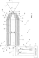
- the burner 9 comprise respective fuel oil lance injectors 15, one of which is schematically shown in figures 2 and 3 .
- the lance injector 15 extends along a central axis A and comprises a supply duct arrangement 17 and a terminal member 18 coupled to downstream end of the supply duct arrangement 17.
- the supply duct arrangement 17 comprises a first tubular body 20, a second tubular body 21, an inner tubular body 22 and an outer tubular body 23. In some embodiments not shown, however, one or both of the inner tubular body 22 and the outer tubular body 23 may not be present and the supply duct arrangement may include only the first tubular body and the second tubular body.
- All the first tubular body 20, second tubular body 21, inner tubular body 22 and outer tubular body 23 extend concentrically along the central axis A.
- a fuel oil supply duct 25 is defined inside the first tubular body 21. More precisely, the inner tubular body 22 extends concentrically inside the first tubular body 20, whereby the fuel oil supply duct 25 is delimited by the first tubular body 21 externally and by the inner tubular body 22 internally.
- a return duct 26 is defined inside the inner tubular body 22 and is coupled to the fuel oil supply duct 25 through the terminal member 18, as explained in detail later on. The return duct may not be present in embodiments not including the inner tubular body.
- the fuel oil supply duct 25 is furthermore coupled to the fuel oil supply line 10a through the fuel oil control valve 11a to receive a flow of fuel oil to be supplied into the combustor assembly 5.
- the return duct 26 is coupled to the return line 10b through the return control valve 11b to return an excess fuel oil to a reservoir (not shown).
- the fuel oil control valve 11a and the return control valve 11b are operated by the controller 3 to adjust a pressure and an amount of fuel oil actually delivered to support combustion.
- a shielding air duct 27 is delimited by the first tubular body 20 internally and by the second tubular body 21 externally.
- the shielding air duct 27 is coupled to the air plenum 6 through an air control valve 28 and receives an airflow to be used as shielding air.
- the control valve 28 may be an orifice.
- each lance injector 15 has a respective air control valve 28, thus meaning that either there is a dedicated air control valve 28 separately for each lance injector 15 (as in the example of figure 2 , see also figure 5 ) or that each lance injector 15 is coupled to an air control valve 28, but air control valves 28 may be shared by several each lance injectors 15.
- a water supply duct 29 is delimited by the second tubular body 21 internally and by the outer tubular body 23 externally and is coupled to the water supply system 12 via the water control valve 14.
- the terminal member 18 has a central fuel oil nozzle 30, coupled to the fuel oil supply duct 25, and an air outlet 31, coupled to the shielding air duct 27 and surrounding the fuel oil nozzle 30.
- the fuel oil nozzle 30 is configured to deliver a fuel oil flow F in a hollow cone pattern with aperture angle ⁇ and the air outlet 31 is configured to direct a shielding air flow AF from the shielding air duct 27 such that the shielding air flow AF crosses the delivered fuel oil flow F.
- direction of an airflow velocity at the air outlet intersects the hollow cone pattern of the fuel oil flow F and, in one embodiment, also intersects the central axis.
- the air outlet 31 has an annular convergent shape.
- a velocity of the shielding air flow AF at the air outlet 31 has a non-zero axial component, parallel to the central axis A, a non-zero radial component, perpendicular to the central axis A, and a zero tangential component, or at least the tangential component is lower than a velocity threshold that allows intersection with the delivered fuel oil flow F.
- An exit angle ⁇ of the velocity of the shielding air flow AF at the air outlet 31, i.e. the angle formed by the velocity of the shielding air flow AF and the central axis A, is for example comprised between 5° and 80° and, preferably, between 30° and 60°. In this range, the shielding air flow AF protects from hot gas recirculation and effectively promotes mixing of air and fuel oil.
- the terminal member 18 comprises a hollow first convergent body 33, a hollow second convergent body 34 and an outer convergent body 35.
- the first convergent body 33 is connected to the first tubular body 20 and to the inner tubular body 22 and forms a fuel delivery chamber 37 fluidly coupled to the fuel oil supply duct 25 and to the fuel oil nozzle 30.
- the fuel oil nozzle 30 is formed in the first convergent body 33 at the injection end 15b of the lance injector 15.
- the fuel delivery chamber 37 is also coupled to the fuel oil return duct 26. Passages 39 provided in the first convergent body 33 of the terminal member 18 upstream of the fuel delivery chamber 37 allow fluid coupling of the fuel oil supply duct 25 with the delivery chamber 37 and the return duct 26. Therefore, part of the fuel oil conveyed by the fuel oil supply duct 25 is delivered through the nozzle 30 and part is returned through the fuel oil return duct 26.
- the second convergent body 34 is connected to the second tubular body 21.
- a convergent section of the shielding air duct 37 is delimited by the first convergent body 33 internally and by the second convergent body 34 externally.
- the configuration of the air outlet 31 is defined by the first convergent body 33 and by the second convergent body 34.
- the first convergent body 33 has a frustoconical end portion 33a and an injection end 34a of the second convergent body 34 has a convergent frustoconical opening 34b surrounding the frustoconical end portion 33a of the first convergent body 33.
- the air outlet 31 is therefore defined by the frustoconical end portion 33a internally and by the frustoconical opening 34b externally.
- the first convergent body 33 has also a frustoconical intermediate portion 33b between the first tubular body 20 and the frustoconical end portion 33a.
- An annular step 33c is defined between the frustoconical intermediate portion 33b and the frustoconical end portion 33a in a plane perpendicular to the central axis A.
- the injection end 34a of the second convergent body 34 has a cylindrical shape and defines an air plenum 38 around the frustoconical end portion 33a of the first convergent body 33, between the convergent section of the shielding air duct 27 and the air outlet 31.
- the outer convergent body 35 extends around the second convergent body 34 and is coupled to the water supply duct 29.
- the injection end 34a of the second convergent body 34 axially projects from the outer convergent body 35 and a water outlet 40, which is coupled to the water supply duct 29, is defined therebetween.
- the water outlet 40 is thus configured to deliver a water flow W around the delivered fuel oil flow F.
- the water outlet 40 may be defined by a single annular opening around the injection end 34a of the second convergent body 34 or by a plurality of openings or holes arranged circumferentially, in accordance with design preferences.
- Figure 4 shows the effect of velocity of the shielding air flow AF on the cone aperture angle ⁇ of the delivered fuel oil flow with different nozzle geometries (e.g. different exit angles ⁇ or return flow).
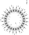
- the burners 9 may be divided into groups.
- a first group of lance injectors 15 the respective air control valves 28 are set to allow a first shielding air flow AF1 to the respective shielding air ducts 27.
- the respective air control valves 28 are set to allow a second shielding air flow AF2, different from the first shielding air flow AF1, to the respective shielding air ducts 27.
- Lance injectors 15 of the first group and of the second group may be alternated.
- the first group and the second group need not contain the same number of lance injectors. Asymmetries in combustion conditions (e.g.
- each lance injector is provided with a respective dedicated air control valve 28.
- a single air control valve may serve several lance injectors.
- a single air control valve may serve all the lance injectors of the first group and another single air control valve may serve all the lance injectors of the second group.
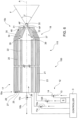
- a gas turbine engine 100 having substantially the structure of the gas turbine engine 1 of figure 1 , comprises air control valves 128 of an adjustable type for supply of shielding air to the lance injectors 15.
- the controller 3 is configured to adjust the air control valves 128 based on a response of the sensors 8.
- the supply of shielding air to the lance injectors 15 and the effect thereof on the shape and mixing rate of delivered fuel oil flow F may be changed during operation of the gas turbine engine 100 in accordance with design preferences.
Landscapes
- Engineering & Computer Science (AREA)
- Chemical & Material Sciences (AREA)
- Combustion & Propulsion (AREA)
- Mechanical Engineering (AREA)
- General Engineering & Computer Science (AREA)
- Nozzles For Spraying Of Liquid Fuel (AREA)
Abstract
Description
- The present invention relates to a fuel oil injector with shielding air supply.
- As is known, operating heavy-duty gas turbine engines on different fuels is quite common and machines accepting both gas (even several types) and fuel oil. Both regulatory authorities and market are imposing increasingly strict requirements on pollutant emissions, efficiency and response, that involve nearly all operating conditions and especially aspects of operating on fuel oil. These requirements may be more easily met when gas turbine engines can be started on gas and switched to fuel oil only when higher load conditions have been reached.
- More and more often, however, gas turbine engines are required to run on fuel oil at any load condition, including low load and even start-up, besides base load. Not only increase of firing temperature is sought to improve efficiency at high load, but also compliant operation at low load in therefore expected. For example, gas turbine engines running exclusively on fuel oil are frequently used as back-up systems for renewable energy market. As intervention of the back-up systems is quite rare, a relatively limited stock of fuel oil is sufficient to avoid discontinuing service and no connection to gas supply is provided, as it would be unnecessarily costly.
- Fuel oil feed is accomplished through lance injector, which however are normally designed for high load and may not prove satisfactory at low load conditions. Therefore, also fuel oil injection has to be carefully designed with a twofold view of optimizing performance and avoiding coking buildup, which may reduce efficiency and even component lifetime.
- Known solutions include lance injectors with concentric feed lines and nozzles dedicated to delivery of fuel oil, water and sometimes fuel gas and/or shielding air, possibly. The innermost line is normally dedicated to the supply (and return, if the case be) of fuel oil, which is delivered through injection nozzles to form a hollow cone and improve combustion. Water may be sprayed around the fuel oil cone, generally for the purpose of cutting NOx emissions. Shielding air, if present, is injected in parallel flow with the fuel oil and surrounds the water layer. Shielding air thus forms a protective cold layer that delays heating up of the fuel oil and slows down reaction kinetics. In addition, shielding air may help purge away fuel oil droplets close to the fuel oil nozzle and prevent coking build up.
- Mixing of fuel oil and air within the aperture of the fuel oil cone plays an important role in combustion, which is influenced by the size of fuel oil droplets. In known lance injectors, however, there is little chance to improve mixing and reduce the average size of the droplets. The presence of a water layer immediately outside the fuel oil cone may even lead to less favorable spread of fuel oil. It would instead desirable to enhance the mixing ratio of fuel with air, thereby setting improved combustion conditions and reducing NOx emissions.
- It is an aim of the present invention to provide a fuel oil injector and a method of controlling a fuel oil injector that allows the above limitations to be overcome or at least reduced.
- According to the present invention, there is provided a lance injector for a gas turbine engine, the lance injector comprising:
- a supply duct arrangement, including at least a first tubular body and a second tubular body, concentrically extending along a central axis; and
- a terminal member coupled to downstream end of the supply duct arrangement;
- wherein a fuel oil supply duct is defined inside the first tubular body and a shielding air duct is delimited by the first tubular body internally and by the second tubular body externally;
- wherein the terminal member has a central fuel oil nozzle, coupled to the fuel oil supply duct, and an air outlet, coupled to the shielding air duct and surrounding the fuel oil nozzle; and
- wherein the fuel oil nozzle is configured to deliver a fuel oil flow in a hollow cone pattern and the air outlet is configured to direct an shielding air flow from the shielding air duct such that the shielding air flow crosses the delivered fuel oil flow.
- The first tubular body separates the fuel oil supply duct and the shielding air duct. No additional fluid layers are thus interposed between the delivered fuel oil flow and the shielding air flow, which therefore interact with each other. In turn, the interaction of the shielding air flow and of delivered fuel oil flow the has several beneficial effects on combustion. In the first place, the shielding air flow improves mixing of fuel and air and helps break the fuel oil stream into small droplets. In this manner, combustion is more efficient and oxidation is improved, thus leading to a reduction in emissions of carbon monoxide. In general, having the shielding air directed towards the centerline of the lance injector promotes interaction and gives additional degrees of freedom in shaping the resulting fuel oil cone spray angle and control of flame position. As a result, combustion dynamics and operation of the burners are remarkably improved.
- Moreover, when the lance injector is not used and the burners operate on gaseous fuels, e.g. with premix burners around the lance injector, shielding air acts as a barrier and protects the fuel oil supply system from hot combustion air recirculation. Separate additional measures, such as blocking or sealing air to purge the fuel oil supply duct, are not required.
- According to an aspect of the invention, a direction of an airflow velocity at the air outlet intersects the delivered fuel oil flow pattern and preferably intersects the central axis.
- Interaction of shielding air and delivered fuel oil flow is enhanced accordingly.
- According to an aspect of the invention, the air outlet has an annular convergent shape.
- The annular convergent shape of the air outlet allows to achieve the desired direction and exit angle of the shielding air and to optimize interaction with the resulting fuel oil cone spray.
- According to an aspect of the invention, the terminal member comprises a hollow first convergent body, connected to the first tubular body and forming a fuel delivery chamber fluidly coupled to the fuel oil supply duct and to the fuel oil nozzle and wherein the fuel oil nozzle is formed in the first convergent body of the terminal member.
- According to an aspect of the invention, the terminal member comprises a hollow second convergent body, connected to the second tubular body, and wherein the shielding air duct has a convergent section delimited by the body internally and by the second convergent body externally.
- In order to favor interaction, the shielding air is kept separated from the fuel oil flow only by the first convergent body, without any other fluid layers in between.
- According to an aspect of the invention, the first convergent body has a frustoconical end portion and an injection end of the second convergent body has a convergent frustoconical opening and wherein the air outlet is defined by the frustoconical end portion internally and by the frustoconical opening externally.
- The geometry of the frustoconical end portion and of the frustoconical opening precisely determines the features of the air outlet and the action of the shielding air flow on the cone of the delivered fuel oil flow.
- According to an aspect of the invention, the first convergent body has a frustoconical intermediate portion between the first tubular body and the frustoconical end portion and wherein an annular step is defined between the frustoconical intermediate portion and the frustoconical end portion in a plane perpendicular to the central axis.
- According to an aspect of the invention, the injection end of the second convergent body has a cylindrical shape and defines an air plenum around the frustoconical end portion of the first convergent body, between the convergent section of the shielding air duct and the air outlet.
- The air plenum around the around the frustoconical end portion of the first convergent body allows to equalize the shielding air flow before ejection, so that the effect on the delivered fuel oil flow may be accurately determined.
- According to an aspect of the invention, the supply duct arrangement comprises an outer tubular body extending coaxially around the first tubular body and the second tubular body, wherein a water supply duct is delimited by the second tubular body internally and by the outer tubular body externally, wherein the terminal member has a water outlet coupled to the water supply duct and configured to deliver a water flow around the delivered fuel oil flow.
- According to an aspect of the invention, the terminal member comprises an outer convergent body extending around the second convergent body and coupled to the water supply duct.
- The water flow may be used to improve control of temperature combustion and pollutant emissions, in particular NOx. As the water duct is arranged around the shielding air duct, however, spraying the water layer does not affect interaction of shielding air and fuel oil. In addition, the combined action with the shielding air flow reduces the requirements in terms of water supply.
- According to an aspect of the invention, the supply duct arrangement comprises an inner tubular body, extending concentrically inside the first tubular body, wherein a fuel oil return duct is defined inside the inner tubular body and is coupled to the fuel delivery chamber and wherein the terminal member has passages coupling the fuel oil supply duct and the fuel oil return duct upstream of the fuel delivery chamber.
- The use of a return line for excess fuel oil allows to optimize pressure and flow condition for delivery of fuel oil through the fuel oil nozzle.
- According the present invention, there is also provided a gas turbine engine, comprising at least one fuel oil injector as defined above, a fuel oil supply system coupled to the fuel oil supply duct and an air source coupled to the shielding air duct.
- According to an aspect of the invention, the gas turbine engine comprises an air control valve for each of the at least one fuel oil injector, the air control valve being configured to set air supply to the shielding air duct of the respective fuel oil injector.
- The air supply to the shielding air duct and therefore the shielding air flow of the lance injectors may be thus adjusted in accordance to circumstances, e.g. to optimize or possibly restore combustion conditions, if changes intervenes during the lifetime of the gas turbine engine.
- According to an aspect of the invention, the gas turbine engine comprises a first group of lance injectors, having the respective air control valves set to allow a first shielding air flow to the respective shielding air ducts, and a second group of lance injectors, having the respective air control valves set to allow a second shielding air flow to the respective shielding air ducts, the second shielding air flow being different from the first shielding air flow.
- Different settings of the lance injectors in the first group and in the second group allow to establish asymmetries in combustion conditions of different burners. Such asymmetries are effective in mitigating pulsations with rotational modes.
- According to an aspect of the invention, the gas turbine engine comprises a controller and a sensors configured to detect operating quantities of the gas turbine engine, wherein at least one air control valve is an adjustable control valve and the controller is configured to adjust the at least one air control valve based on a response of the sensors.
- Accordingly, the shielding air flow may be dynamically adjusted during operation of the gas turbine engine by a feedback action in response to changing operating condition, for example because of ageing or varying pulsation regimes.
- The present invention will now be described with reference to the accompanying drawings, which show a number of non-limitative embodiments thereof, in which:
-
figure 1 is a simplified block diagram of a gas turbine engine; -
figure 2 is a simplified longitudinal cross section of a lance injector incorporated in the gas turbine engine offigure 1 and made in accordance with an embodiment of the present invention; -
figure 3 shows an enlarged detail of the lance injector offigure 2 ; -
figure 4 is a graph showing quantities relating to the lance injector offigure 2 ; -
figure 5 is a schematic front view of a combustor assembly of the gas turbine engine offigure 1 ; and -
figure 6 is a simplified longitudinal cross section of a lance injector in accordance with another embodiment of the present invention. - With reference to
Figure 1 , number 1 defines a gasturbine plant as a whole comprising agas turbine engine 2 and acontroller 3. - The
gas turbine engine 2, in turn, comprises acompressor 4, acombustor assembly 5 and an expansion section orturbine 7. Moreover,sensors 8 are arranged and configured to sense operating quantities of thegas turbine engine 2 and to send measurement signals SM to thecontroller 3. - The
compressor 4 feeds thecombustor assembly 5 with a flow of air drawn from outside. - The
combustor assembly 5 comprises a plurality ofburner assemblies 9, which cause the combustion inside thecombustor assembly 5, of a mixture of air and fuel. Anair plenum 6, coupled to theburners 9, is supplied with compressed air by thecompressor 4 and defines a compressed air source for theburners 9. - The
turbine 7 receives and expands a flow of burnt hot gas from thecombustor assembly 5 to extract mechanical work, which is transferred to an external user, typically an electric generator, which is not shown here. - The fuel may be of several types and includes at least fuel oil. In addition to fuel oil, the
gas turbine engine 2 may be structured to work also on other types of fuel, both gaseous and liquid. Fuel oil is supplied to theburners 9 by afuel supply system 10, that comprises a fueloil supply line 10a and areturn line 10b. At least a fueloil control valve 11a and areturn control valve 11b are provided along the fueloil supply line 10a and thereturn line 10b, respectively. - The gas turbine engine 1 also comprises a
water supply system 12, configured to supply a controlled flow of water to theburner assemblies 9 for the purpose of reducing NOx emissions. Thewater supply system 12 includes at least onewater supply line 13 and awater control valve 14, operable to adjust water supply to theburner assemblies 9. - The
controller 3 is configured to determine set-points of the gas turbine engine 1 for desired operating conditions and to use actuators of the gas turbine engine 1, including the fueloil control valve 11a and thereturn control valve 11b, so that set-points may be achieved. - The
burner 9 comprise respective fueloil lance injectors 15, one of which is schematically shown infigures 2 and3 . - The
lance injector 15 extends along a central axis A and comprises asupply duct arrangement 17 and aterminal member 18 coupled to downstream end of thesupply duct arrangement 17. - The
supply duct arrangement 17 comprises a firsttubular body 20, a secondtubular body 21, an innertubular body 22 and an outertubular body 23. In some embodiments not shown, however, one or both of the innertubular body 22 and the outertubular body 23 may not be present and the supply duct arrangement may include only the first tubular body and the second tubular body. - All the first
tubular body 20, secondtubular body 21, innertubular body 22 and outertubular body 23 extend concentrically along the central axis A. - A fuel
oil supply duct 25 is defined inside the firsttubular body 21. More precisely, the innertubular body 22 extends concentrically inside the firsttubular body 20, whereby the fueloil supply duct 25 is delimited by the firsttubular body 21 externally and by the innertubular body 22 internally. Areturn duct 26 is defined inside the innertubular body 22 and is coupled to the fueloil supply duct 25 through theterminal member 18, as explained in detail later on. The return duct may not be present in embodiments not including the inner tubular body. The fueloil supply duct 25 is furthermore coupled to the fueloil supply line 10a through the fueloil control valve 11a to receive a flow of fuel oil to be supplied into thecombustor assembly 5. Thereturn duct 26 is coupled to thereturn line 10b through thereturn control valve 11b to return an excess fuel oil to a reservoir (not shown). The fueloil control valve 11a and thereturn control valve 11b are operated by thecontroller 3 to adjust a pressure and an amount of fuel oil actually delivered to support combustion. - A shielding
air duct 27 is delimited by the firsttubular body 20 internally and by the secondtubular body 21 externally. The shieldingair duct 27 is coupled to theair plenum 6 through anair control valve 28 and receives an airflow to be used as shielding air. In one embodiment, thecontrol valve 28 may be an orifice. Moreover, eachlance injector 15 has a respectiveair control valve 28, thus meaning that either there is a dedicatedair control valve 28 separately for each lance injector 15 (as in the example offigure 2 , see alsofigure 5 ) or that eachlance injector 15 is coupled to anair control valve 28, butair control valves 28 may be shared by several eachlance injectors 15. - A
water supply duct 29 is delimited by the secondtubular body 21 internally and by the outertubular body 23 externally and is coupled to thewater supply system 12 via thewater control valve 14. - The
terminal member 18 has a centralfuel oil nozzle 30, coupled to the fueloil supply duct 25, and anair outlet 31, coupled to the shieldingair duct 27 and surrounding thefuel oil nozzle 30. Thefuel oil nozzle 30 is configured to deliver a fuel oil flow F in a hollow cone pattern with aperture angle β and theair outlet 31 is configured to direct a shielding air flow AF from the shieldingair duct 27 such that the shielding air flow AF crosses the delivered fuel oil flow F. Specifically, direction of an airflow velocity at the air outlet intersects the hollow cone pattern of the fuel oil flow F and, in one embodiment, also intersects the central axis. To this end, theair outlet 31 has an annular convergent shape. Here and in what follows, "convergent" is to be understood with reference to a direction from asupply end 15a to aninjection end 15b of thelance injector 15. This direction is also the direction of flow of fuel oil supplied trough the fueloil supply duct 25 and a of shielding air supplied through the shielding air duct 27 (as well as of water supplied through thewater supply duct 29, if present), whereas the return fuel oil flows through the return duct 26 (if present) in an opposite direction. Therefore, "convergent" here means that a radial dimension perpendicularly to or a distance from the central axis A decreases in the direction from thesupply end 15a to theinjection end 15b of thelance injector 15. On account of the annular convergent shape of theair outlet 31, a velocity of the shielding air flow AF at theair outlet 31 has a non-zero axial component, parallel to the central axis A, a non-zero radial component, perpendicular to the central axis A, and a zero tangential component, or at least the tangential component is lower than a velocity threshold that allows intersection with the delivered fuel oil flow F. - An exit angle α of the velocity of the shielding air flow AF at the
air outlet 31, i.e. the angle formed by the velocity of the shielding air flow AF and the central axis A, is for example comprised between 5° and 80° and, preferably, between 30° and 60°. In this range, the shielding air flow AF protects from hot gas recirculation and effectively promotes mixing of air and fuel oil. - The
terminal member 18 comprises a hollow firstconvergent body 33, a hollow secondconvergent body 34 and an outerconvergent body 35. The firstconvergent body 33 is connected to the firsttubular body 20 and to the innertubular body 22 and forms afuel delivery chamber 37 fluidly coupled to the fueloil supply duct 25 and to thefuel oil nozzle 30. Thefuel oil nozzle 30 is formed in the firstconvergent body 33 at theinjection end 15b of thelance injector 15. Thefuel delivery chamber 37 is also coupled to the fueloil return duct 26.Passages 39 provided in the firstconvergent body 33 of theterminal member 18 upstream of thefuel delivery chamber 37 allow fluid coupling of the fueloil supply duct 25 with thedelivery chamber 37 and thereturn duct 26. Therefore, part of the fuel oil conveyed by the fueloil supply duct 25 is delivered through thenozzle 30 and part is returned through the fueloil return duct 26. - The second
convergent body 34 is connected to the secondtubular body 21. Thus, a convergent section of the shieldingair duct 37 is delimited by the firstconvergent body 33 internally and by the secondconvergent body 34 externally. In one embodiment, the configuration of theair outlet 31 is defined by the firstconvergent body 33 and by the secondconvergent body 34. As shown in greater detail infigure 3 , the firstconvergent body 33 has afrustoconical end portion 33a and aninjection end 34a of the secondconvergent body 34 has a convergent frustoconical opening 34b surrounding thefrustoconical end portion 33a of the firstconvergent body 33. Theair outlet 31 is therefore defined by thefrustoconical end portion 33a internally and by the frustoconical opening 34b externally. - The first
convergent body 33 has also a frustoconicalintermediate portion 33b between the firsttubular body 20 and thefrustoconical end portion 33a. Anannular step 33c is defined between the frustoconicalintermediate portion 33b and thefrustoconical end portion 33a in a plane perpendicular to the central axis A. Theinjection end 34a of the secondconvergent body 34 has a cylindrical shape and defines anair plenum 38 around thefrustoconical end portion 33a of the firstconvergent body 33, between the convergent section of the shieldingair duct 27 and theair outlet 31. - The outer
convergent body 35 extends around the secondconvergent body 34 and is coupled to thewater supply duct 29. Theinjection end 34a of the secondconvergent body 34 axially projects from the outerconvergent body 35 and awater outlet 40, which is coupled to thewater supply duct 29, is defined therebetween. Thewater outlet 40 is thus configured to deliver a water flow W around the delivered fuel oil flow F. Thewater outlet 40 may be defined by a single annular opening around theinjection end 34a of the secondconvergent body 34 or by a plurality of openings or holes arranged circumferentially, in accordance with design preferences. -
Figure 4 shows the effect of velocity of the shielding air flow AF on the cone aperture angle β of the delivered fuel oil flow with different nozzle geometries (e.g. different exit angles α or return flow). - With reference to
figure 5 , in the gas turbine engine 1 theburners 9 may be divided into groups. In a first group oflance injectors 15, the respectiveair control valves 28 are set to allow a first shielding air flow AF1 to the respectiveshielding air ducts 27. In a second group oflance injectors 15, the respectiveair control valves 28 are set to allow a second shielding air flow AF2, different from the first shielding air flow AF1, to the respectiveshielding air ducts 27. Lance injectors 15 of the first group and of the second group may be alternated. The first group and the second group need not contain the same number of lance injectors. Asymmetries in combustion conditions (e.g. cone aperture angle β of the delivered fuel oil flow) help reduce pulsations with rotational modes. In the embodiment offigure 5 , each lance injector is provided with a respective dedicatedair control valve 28. In other embodiments, however, a single air control valve may serve several lance injectors. For example, a single air control valve may serve all the lance injectors of the first group and another single air control valve may serve all the lance injectors of the second group. - With reference to
figure 6 , agas turbine engine 100, having substantially the structure of the gas turbine engine 1 offigure 1 , comprisesair control valves 128 of an adjustable type for supply of shielding air to thelance injectors 15. In this case, thecontroller 3 is configured to adjust theair control valves 128 based on a response of thesensors 8. Thus, the supply of shielding air to thelance injectors 15 and the effect thereof on the shape and mixing rate of delivered fuel oil flow F may be changed during operation of thegas turbine engine 100 in accordance with design preferences. - Finally, it is clear that modifications and variants may be made to the injector described herein without departing from the scope of the present invention, as defined in the appended claims.
Claims (15)
- A lance injector for a gas turbine engine, the lance injector comprising:a supply duct arrangement (17), including at least a first tubular body (20) and a second tubular body (21), concentrically extending along a central axis (A); anda terminal member (18) coupled to downstream end of the supply duct arrangement (17);wherein a fuel oil supply duct (25) is defined inside the first tubular body (20) and a shielding air duct (27) is delimited by the first tubular body (20) internally and by the second tubular body (21) externally;wherein the terminal member (18) has a central fuel oil nozzle (30), coupled to the fuel oil supply duct (25), and an air outlet (31), coupled to the shielding air duct (27) and surrounding the fuel oil nozzle (30); andwherein the fuel oil nozzle (30) is configured to deliver a fuel oil flow (F) in a hollow cone pattern and the air outlet (31) is configured to direct a shielding air flow from the shielding air duct (27) such that the shielding air flow crosses the delivered fuel oil flow (F).
- The lance injector according to claim 1, wherein a direction of an airflow velocity (V) at the air outlet (31) intersects the delivered fuel oil flow (F) and preferably intersects the central axis (A).
- The lance injector according to claim 1 or 2, wherein the air outlet (31) has an annular convergent shape.
- The lance injector according to any one of the preceding claims, wherein the terminal member (18) comprises a hollow first convergent body (33), connected to the first tubular body (20) and forming a fuel delivery chamber (37) fluidly coupled to the fuel oil supply duct (25) and to the fuel oil nozzle (30) and wherein the fuel oil nozzle (30) is formed in the first convergent body (33) of the terminal member (18).
- The lance injector according to claim 4, wherein the terminal member (18) comprises a hollow second convergent body (34), connected to the second tubular body (21), and wherein the shielding air duct (27) has a convergent section delimited by the first convergent body (33) internally and by the second convergent body (34) externally.
- The lance injector according to claim 5, wherein the first convergent body (33) has a frustoconical end portion (33a) and an injection end (34a) of the second convergent body (34) has a convergent frustoconical opening (34b) and wherein the air outlet (31) is defined by the frustoconical end portion (33a) internally and by the frustoconical opening (34b) externally.
- The lance injector according to claim 6, wherein the first convergent body (33) has a frustoconical intermediate portion (33b) between the first tubular body (20) and the frustoconical end portion (33a) and wherein an annular step (33c) is defined between the frustoconical intermediate portion (33b) and the frustoconical end portion (33a) in a plane perpendicular to the central axis (A).
- The lance injector according to claim 7, wherein the injection end (34a) of the second convergent body (34) has a cylindrical shape and defines an air plenum (38) around the frustoconical end portion (33a) of the first convergent body (33), between the convergent section of the shielding air duct (27) and the air outlet (31).
- The lance injector according to any one of claims 5 to 8, wherein the supply duct arrangement (17) comprises an outer tubular body (23) extending coaxially around the first tubular body (20) and the second tubular body (21), wherein a water supply duct (29) is delimited by the second tubular body (21) internally and by the outer tubular body (23) externally, wherein the terminal member (18) has a water outlet (40) coupled to the water supply duct (29) and configured to deliver a water flow (W) around the delivered fuel oil flow (F).
- The lance injector according to claim 9, wherein the terminal member (18) comprises an outer convergent body (35) extending around the second convergent body (34) and coupled to the water supply duct (29).
- The lance injector according to any one of claims 4 to 10, wherein the supply duct arrangement (17) comprises an inner tubular body (22), extending concentrically inside the first tubular body (20), wherein a fuel oil return duct (26) is defined inside the inner tubular body (22) and is coupled to the fuel delivery chamber (37) and wherein the terminal member (18) has passages (39) coupling the fuel oil supply duct (25) and the fuel oil return duct (26) upstream of the fuel delivery chamber (37).
- A gas turbine engine, comprising at least one fuel oil injector (15) according to any one of the preceding claims, a fuel oil supply system (10) coupled to the fuel oil supply duct (25) and an air source (6) coupled to the shielding air duct (27).
- The gas turbine engine according to claim 12, comprising an air control valve (28; 128) for each of the at least one fuel oil injector, the air control valve (28; 128) being configured to set air supply to the shielding air duct (27) of the respective fuel oil injector (15).
- The gas turbine engine according to claim 13, comprising a first group of lance injectors, having the respective air control valves (28; 128) set to allow a first shielding air flow (AF1) to the respective shielding air ducts (27), and a second group of lance injectors, having the respective air control valves (28; 128) set to allow a second shielding air flow (AF2) to the respective shielding air ducts (27), the second shielding air (AF2) flow being different from the first shielding air flow (AF1).
- The gas turbine engine according to claim 13 or 14, comprising a comprising a controller (3) and a sensors (8) configured to detect operating quantities of the gas turbine engine (100), wherein at least one air control valve (128) is an adjustable control valve and the controller is configured to adjust the at least one air control valve (128) based on a response of the sensors (8).
Priority Applications (2)
| Application Number | Priority Date | Filing Date | Title |
|---|---|---|---|
| EP22425022.5A EP4279812B1 (en) | 2022-05-18 | 2022-05-18 | Fuel oil injector with shielding air supply |
| CN202310554638.9A CN117090690A (en) | 2022-05-18 | 2023-05-17 | Fuel injector with shielding air supply |
Applications Claiming Priority (1)
| Application Number | Priority Date | Filing Date | Title |
|---|---|---|---|
| EP22425022.5A EP4279812B1 (en) | 2022-05-18 | 2022-05-18 | Fuel oil injector with shielding air supply |
Publications (2)
| Publication Number | Publication Date |
|---|---|
| EP4279812A1 true EP4279812A1 (en) | 2023-11-22 |
| EP4279812B1 EP4279812B1 (en) | 2025-08-13 |
Family
ID=82483147
Family Applications (1)
| Application Number | Title | Priority Date | Filing Date |
|---|---|---|---|
| EP22425022.5A Active EP4279812B1 (en) | 2022-05-18 | 2022-05-18 | Fuel oil injector with shielding air supply |
Country Status (2)
| Country | Link |
|---|---|
| EP (1) | EP4279812B1 (en) |
| CN (1) | CN117090690A (en) |
Citations (6)
| Publication number | Priority date | Publication date | Assignee | Title |
|---|---|---|---|---|
| US20060080966A1 (en) * | 2004-10-14 | 2006-04-20 | General Electric Company | Low-cost dual-fuel combustor and related method |
| US20130125554A1 (en) * | 2010-08-06 | 2013-05-23 | Franklin F. Mittricker | Systems and Methods For Exhaust Gas Extraction |
| US20140060071A1 (en) * | 2011-05-03 | 2014-03-06 | Siemens Aktiengesellschaft | Cooled pilot fuel lance |
| US20140123668A1 (en) * | 2012-11-02 | 2014-05-08 | Exxonmobil Upstream Research Company | System and method for diffusion combustion with fuel-diluent mixing in a stoichiometric exhaust gas recirculation gas turbine system |
| EP3137815A1 (en) * | 2014-05-02 | 2017-03-08 | Siemens Aktiengesellschaft | Combustor burner arrangement |
| US20170211805A1 (en) * | 2014-08-14 | 2017-07-27 | Siemens Aktiengesellschaft | Multi-functional fuel nozzle with an atomizer array |
Family Cites Families (1)
| Publication number | Priority date | Publication date | Assignee | Title |
|---|---|---|---|---|
| EP3078913A1 (en) * | 2015-04-09 | 2016-10-12 | Siemens Aktiengesellschaft | Combustor burner arrangement |
-
2022
- 2022-05-18 EP EP22425022.5A patent/EP4279812B1/en active Active
-
2023
- 2023-05-17 CN CN202310554638.9A patent/CN117090690A/en active Pending
Patent Citations (6)
| Publication number | Priority date | Publication date | Assignee | Title |
|---|---|---|---|---|
| US20060080966A1 (en) * | 2004-10-14 | 2006-04-20 | General Electric Company | Low-cost dual-fuel combustor and related method |
| US20130125554A1 (en) * | 2010-08-06 | 2013-05-23 | Franklin F. Mittricker | Systems and Methods For Exhaust Gas Extraction |
| US20140060071A1 (en) * | 2011-05-03 | 2014-03-06 | Siemens Aktiengesellschaft | Cooled pilot fuel lance |
| US20140123668A1 (en) * | 2012-11-02 | 2014-05-08 | Exxonmobil Upstream Research Company | System and method for diffusion combustion with fuel-diluent mixing in a stoichiometric exhaust gas recirculation gas turbine system |
| EP3137815A1 (en) * | 2014-05-02 | 2017-03-08 | Siemens Aktiengesellschaft | Combustor burner arrangement |
| US20170211805A1 (en) * | 2014-08-14 | 2017-07-27 | Siemens Aktiengesellschaft | Multi-functional fuel nozzle with an atomizer array |
Also Published As
| Publication number | Publication date |
|---|---|
| EP4279812B1 (en) | 2025-08-13 |
| CN117090690A (en) | 2023-11-21 |
Similar Documents
| Publication | Publication Date | Title |
|---|---|---|
| EP1750056B1 (en) | Fuel injector | |
| US9046039B2 (en) | Staged pilots in pure airblast injectors for gas turbine engines | |
| US8096135B2 (en) | Pure air blast fuel injector | |
| KR101867690B1 (en) | Gas turbine combustor | |
| EP0800041B1 (en) | Gas turbine engine combustion equipment | |
| JP4024520B2 (en) | Burner system with staged fuel spray device and method for operating the burner system | |
| KR100372907B1 (en) | A method for staging fuel in a turbine between diffusion and premixed operations | |
| US6532726B2 (en) | Gas-turbine engine combustion system | |
| EP1323982B1 (en) | Fuel nozzle for a gas turbine engine | |
| EP2309187A2 (en) | Dual fuel can combustor with automatic liquid fuel purge | |
| US20100263382A1 (en) | Dual orifice pilot fuel injector | |
| EP0617779B1 (en) | Low emission combustion nozzle for use with a gas turbine engine | |
| JP2007155170A (en) | Fuel nozzle, gas turbine combustor, fuel nozzle for gas turbine combustor, and modification method for gas turbine combustor | |
| JP2016109129A (en) | Fuel supply system for gas turbine engine | |
| EP2592351B1 (en) | Staged pilots in pure airblast injectors for gas turbine engines | |
| CN1236227C (en) | Method and device for supplying fuel to a premix burner | |
| CN107110505A (en) | The gas turbine unit and the method for the burner of supply gas turbine unit supplied with multithread fluid fuel | |
| EP4206535B1 (en) | Burner assembly with in-line injectors | |
| EP4279812B1 (en) | Fuel oil injector with shielding air supply | |
| JP2013234769A (en) | Gas turbine combustor and operation method of gas turbine | |
| JP2009024669A (en) | Apparatus for actively controlling fuel flow to a gas turbine engine combustor mixer assembly | |
| EP4187072B1 (en) | Fuel oil injector | |
| US20170307220A1 (en) | Pilot liquid fuel lance, pilot liquid fuel system and method of use | |
| GB2292793A (en) | Turbine combustion chamber | |
| HK1125688A1 (en) | Combustor and a fuel supply method for the combustor |
Legal Events
| Date | Code | Title | Description |
|---|---|---|---|
| PUAI | Public reference made under article 153(3) epc to a published international application that has entered the european phase |
Free format text: ORIGINAL CODE: 0009012 |
|
| STAA | Information on the status of an ep patent application or granted ep patent |
Free format text: STATUS: THE APPLICATION HAS BEEN PUBLISHED |
|
| AK | Designated contracting states |
Kind code of ref document: A1 Designated state(s): AL AT BE BG CH CY CZ DE DK EE ES FI FR GB GR HR HU IE IS IT LI LT LU LV MC MK MT NL NO PL PT RO RS SE SI SK SM TR |
|
| STAA | Information on the status of an ep patent application or granted ep patent |
Free format text: STATUS: REQUEST FOR EXAMINATION WAS MADE |
|
| P01 | Opt-out of the competence of the unified patent court (upc) registered |
Effective date: 20240430 |
|
| 17P | Request for examination filed |
Effective date: 20240522 |
|
| RBV | Designated contracting states (corrected) |
Designated state(s): AL AT BE BG CH CY CZ DE DK EE ES FI FR GB GR HR HU IE IS IT LI LT LU LV MC MK MT NL NO PL PT RO RS SE SI SK SM TR |
|
| STAA | Information on the status of an ep patent application or granted ep patent |
Free format text: STATUS: EXAMINATION IS IN PROGRESS |
|
| 17Q | First examination report despatched |
Effective date: 20241024 |
|
| GRAP | Despatch of communication of intention to grant a patent |
Free format text: ORIGINAL CODE: EPIDOSNIGR1 |
|
| STAA | Information on the status of an ep patent application or granted ep patent |
Free format text: STATUS: GRANT OF PATENT IS INTENDED |
|
| INTG | Intention to grant announced |
Effective date: 20250310 |
|
| GRAS | Grant fee paid |
Free format text: ORIGINAL CODE: EPIDOSNIGR3 |
|
| GRAA | (expected) grant |
Free format text: ORIGINAL CODE: 0009210 |
|
| STAA | Information on the status of an ep patent application or granted ep patent |
Free format text: STATUS: THE PATENT HAS BEEN GRANTED |
|
| AK | Designated contracting states |
Kind code of ref document: B1 Designated state(s): AL AT BE BG CH CY CZ DE DK EE ES FI FR GB GR HR HU IE IS IT LI LT LU LV MC MK MT NL NO PL PT RO RS SE SI SK SM TR |
|
| REG | Reference to a national code |
Ref country code: GB Ref legal event code: FG4D |
|
| REG | Reference to a national code |
Ref country code: CH Ref legal event code: EP |
|
| REG | Reference to a national code |
Ref country code: DE Ref legal event code: R096 Ref document number: 602022019364 Country of ref document: DE |
|
| REG | Reference to a national code |
Ref country code: IE Ref legal event code: FG4D |
|
| REG | Reference to a national code |
Ref country code: NL Ref legal event code: MP Effective date: 20250813 |
|
| PG25 | Lapsed in a contracting state [announced via postgrant information from national office to epo] |
Ref country code: IS Free format text: LAPSE BECAUSE OF FAILURE TO SUBMIT A TRANSLATION OF THE DESCRIPTION OR TO PAY THE FEE WITHIN THE PRESCRIBED TIME-LIMIT Effective date: 20251213 |
|
| PG25 | Lapsed in a contracting state [announced via postgrant information from national office to epo] |
Ref country code: NO Free format text: LAPSE BECAUSE OF FAILURE TO SUBMIT A TRANSLATION OF THE DESCRIPTION OR TO PAY THE FEE WITHIN THE PRESCRIBED TIME-LIMIT Effective date: 20251113 |
|
| REG | Reference to a national code |
Ref country code: LT Ref legal event code: MG9D |
|
| PG25 | Lapsed in a contracting state [announced via postgrant information from national office to epo] |
Ref country code: PT Free format text: LAPSE BECAUSE OF FAILURE TO SUBMIT A TRANSLATION OF THE DESCRIPTION OR TO PAY THE FEE WITHIN THE PRESCRIBED TIME-LIMIT Effective date: 20251215 |
|
| PG25 | Lapsed in a contracting state [announced via postgrant information from national office to epo] |
Ref country code: FI Free format text: LAPSE BECAUSE OF FAILURE TO SUBMIT A TRANSLATION OF THE DESCRIPTION OR TO PAY THE FEE WITHIN THE PRESCRIBED TIME-LIMIT Effective date: 20250813 |
|
| PG25 | Lapsed in a contracting state [announced via postgrant information from national office to epo] |
Ref country code: HR Free format text: LAPSE BECAUSE OF FAILURE TO SUBMIT A TRANSLATION OF THE DESCRIPTION OR TO PAY THE FEE WITHIN THE PRESCRIBED TIME-LIMIT Effective date: 20250813 Ref country code: NL Free format text: LAPSE BECAUSE OF FAILURE TO SUBMIT A TRANSLATION OF THE DESCRIPTION OR TO PAY THE FEE WITHIN THE PRESCRIBED TIME-LIMIT Effective date: 20250813 |
|
| PG25 | Lapsed in a contracting state [announced via postgrant information from national office to epo] |
Ref country code: GR Free format text: LAPSE BECAUSE OF FAILURE TO SUBMIT A TRANSLATION OF THE DESCRIPTION OR TO PAY THE FEE WITHIN THE PRESCRIBED TIME-LIMIT Effective date: 20251114 |
|
| PG25 | Lapsed in a contracting state [announced via postgrant information from national office to epo] |
Ref country code: SE Free format text: LAPSE BECAUSE OF FAILURE TO SUBMIT A TRANSLATION OF THE DESCRIPTION OR TO PAY THE FEE WITHIN THE PRESCRIBED TIME-LIMIT Effective date: 20250813 |
|
| PG25 | Lapsed in a contracting state [announced via postgrant information from national office to epo] |
Ref country code: LV Free format text: LAPSE BECAUSE OF FAILURE TO SUBMIT A TRANSLATION OF THE DESCRIPTION OR TO PAY THE FEE WITHIN THE PRESCRIBED TIME-LIMIT Effective date: 20250813 |
|
| PG25 | Lapsed in a contracting state [announced via postgrant information from national office to epo] |
Ref country code: BG Free format text: LAPSE BECAUSE OF FAILURE TO SUBMIT A TRANSLATION OF THE DESCRIPTION OR TO PAY THE FEE WITHIN THE PRESCRIBED TIME-LIMIT Effective date: 20250813 Ref country code: PL Free format text: LAPSE BECAUSE OF FAILURE TO SUBMIT A TRANSLATION OF THE DESCRIPTION OR TO PAY THE FEE WITHIN THE PRESCRIBED TIME-LIMIT Effective date: 20250813 |
|
| PG25 | Lapsed in a contracting state [announced via postgrant information from national office to epo] |
Ref country code: RS Free format text: LAPSE BECAUSE OF FAILURE TO SUBMIT A TRANSLATION OF THE DESCRIPTION OR TO PAY THE FEE WITHIN THE PRESCRIBED TIME-LIMIT Effective date: 20251113 |
|
| PG25 | Lapsed in a contracting state [announced via postgrant information from national office to epo] |
Ref country code: ES Free format text: LAPSE BECAUSE OF FAILURE TO SUBMIT A TRANSLATION OF THE DESCRIPTION OR TO PAY THE FEE WITHIN THE PRESCRIBED TIME-LIMIT Effective date: 20250813 |
|
| REG | Reference to a national code |
Ref country code: AT Ref legal event code: MK05 Ref document number: 1824997 Country of ref document: AT Kind code of ref document: T Effective date: 20250813 |
|
| PG25 | Lapsed in a contracting state [announced via postgrant information from national office to epo] |
Ref country code: SM Free format text: LAPSE BECAUSE OF FAILURE TO SUBMIT A TRANSLATION OF THE DESCRIPTION OR TO PAY THE FEE WITHIN THE PRESCRIBED TIME-LIMIT Effective date: 20250813 |
|
| PG25 | Lapsed in a contracting state [announced via postgrant information from national office to epo] |
Ref country code: DK Free format text: LAPSE BECAUSE OF FAILURE TO SUBMIT A TRANSLATION OF THE DESCRIPTION OR TO PAY THE FEE WITHIN THE PRESCRIBED TIME-LIMIT Effective date: 20250813 |
|
| PG25 | Lapsed in a contracting state [announced via postgrant information from national office to epo] |
Ref country code: AT Free format text: LAPSE BECAUSE OF FAILURE TO SUBMIT A TRANSLATION OF THE DESCRIPTION OR TO PAY THE FEE WITHIN THE PRESCRIBED TIME-LIMIT Effective date: 20250813 |
|
| PG25 | Lapsed in a contracting state [announced via postgrant information from national office to epo] |
Ref country code: CZ Free format text: LAPSE BECAUSE OF FAILURE TO SUBMIT A TRANSLATION OF THE DESCRIPTION OR TO PAY THE FEE WITHIN THE PRESCRIBED TIME-LIMIT Effective date: 20250813 |
|
| PG25 | Lapsed in a contracting state [announced via postgrant information from national office to epo] |
Ref country code: EE Free format text: LAPSE BECAUSE OF FAILURE TO SUBMIT A TRANSLATION OF THE DESCRIPTION OR TO PAY THE FEE WITHIN THE PRESCRIBED TIME-LIMIT Effective date: 20250813 Ref country code: SK Free format text: LAPSE BECAUSE OF FAILURE TO SUBMIT A TRANSLATION OF THE DESCRIPTION OR TO PAY THE FEE WITHIN THE PRESCRIBED TIME-LIMIT Effective date: 20250813 |