EP4279729A1 - Engine pre turbine pressure monitoring system - Google Patents
Engine pre turbine pressure monitoring system Download PDFInfo
- Publication number
- EP4279729A1 EP4279729A1 EP23174287.5A EP23174287A EP4279729A1 EP 4279729 A1 EP4279729 A1 EP 4279729A1 EP 23174287 A EP23174287 A EP 23174287A EP 4279729 A1 EP4279729 A1 EP 4279729A1
- Authority
- EP
- European Patent Office
- Prior art keywords
- turbine
- pressure
- normalized
- temperature
- power
- Prior art date
- Legal status (The legal status is an assumption and is not a legal conclusion. Google has not performed a legal analysis and makes no representation as to the accuracy of the status listed.)
- Granted
Links
Images


Classifications
-
- G—PHYSICS
- G01—MEASURING; TESTING
- G01M—TESTING STATIC OR DYNAMIC BALANCE OF MACHINES OR STRUCTURES; TESTING OF STRUCTURES OR APPARATUS, NOT OTHERWISE PROVIDED FOR
- G01M15/00—Testing of engines
- G01M15/04—Testing internal-combustion engines
- G01M15/09—Testing internal-combustion engines by monitoring pressure in fluid ducts, e.g. in lubrication or cooling parts
-
- F—MECHANICAL ENGINEERING; LIGHTING; HEATING; WEAPONS; BLASTING
- F02—COMBUSTION ENGINES; HOT-GAS OR COMBUSTION-PRODUCT ENGINE PLANTS
- F02D—CONTROLLING COMBUSTION ENGINES
- F02D41/00—Electrical control of supply of combustible mixture or its constituents
- F02D41/02—Circuit arrangements for generating control signals
- F02D41/14—Introducing closed-loop corrections
- F02D41/1438—Introducing closed-loop corrections using means for determining characteristics of the combustion gases; Sensors therefor
- F02D41/1444—Introducing closed-loop corrections using means for determining characteristics of the combustion gases; Sensors therefor characterised by the characteristics of the combustion gases
- F02D41/1448—Introducing closed-loop corrections using means for determining characteristics of the combustion gases; Sensors therefor characterised by the characteristics of the combustion gases the characteristics being an exhaust gas pressure
- F02D41/145—Introducing closed-loop corrections using means for determining characteristics of the combustion gases; Sensors therefor characterised by the characteristics of the combustion gases the characteristics being an exhaust gas pressure with determination means using an estimation
-
- F—MECHANICAL ENGINEERING; LIGHTING; HEATING; WEAPONS; BLASTING
- F02—COMBUSTION ENGINES; HOT-GAS OR COMBUSTION-PRODUCT ENGINE PLANTS
- F02B—INTERNAL-COMBUSTION PISTON ENGINES; COMBUSTION ENGINES IN GENERAL
- F02B37/00—Engines characterised by provision of pumps driven at least for part of the time by exhaust
- F02B37/12—Control of the pumps
- F02B37/24—Control of the pumps by using pumps or turbines with adjustable guide vanes
-
- F—MECHANICAL ENGINEERING; LIGHTING; HEATING; WEAPONS; BLASTING
- F02—COMBUSTION ENGINES; HOT-GAS OR COMBUSTION-PRODUCT ENGINE PLANTS
- F02D—CONTROLLING COMBUSTION ENGINES
- F02D41/00—Electrical control of supply of combustible mixture or its constituents
- F02D41/0002—Controlling intake air
- F02D41/0007—Controlling intake air for control of turbo-charged or super-charged engines
-
- F—MECHANICAL ENGINEERING; LIGHTING; HEATING; WEAPONS; BLASTING
- F02—COMBUSTION ENGINES; HOT-GAS OR COMBUSTION-PRODUCT ENGINE PLANTS
- F02D—CONTROLLING COMBUSTION ENGINES
- F02D41/00—Electrical control of supply of combustible mixture or its constituents
- F02D41/02—Circuit arrangements for generating control signals
- F02D41/14—Introducing closed-loop corrections
- F02D41/1438—Introducing closed-loop corrections using means for determining characteristics of the combustion gases; Sensors therefor
- F02D41/1444—Introducing closed-loop corrections using means for determining characteristics of the combustion gases; Sensors therefor characterised by the characteristics of the combustion gases
- F02D41/1445—Introducing closed-loop corrections using means for determining characteristics of the combustion gases; Sensors therefor characterised by the characteristics of the combustion gases the characteristics being related to the exhaust flow
-
- F—MECHANICAL ENGINEERING; LIGHTING; HEATING; WEAPONS; BLASTING
- F02—COMBUSTION ENGINES; HOT-GAS OR COMBUSTION-PRODUCT ENGINE PLANTS
- F02D—CONTROLLING COMBUSTION ENGINES
- F02D41/00—Electrical control of supply of combustible mixture or its constituents
- F02D41/02—Circuit arrangements for generating control signals
- F02D41/14—Introducing closed-loop corrections
- F02D41/1438—Introducing closed-loop corrections using means for determining characteristics of the combustion gases; Sensors therefor
- F02D41/1444—Introducing closed-loop corrections using means for determining characteristics of the combustion gases; Sensors therefor characterised by the characteristics of the combustion gases
- F02D41/1446—Introducing closed-loop corrections using means for determining characteristics of the combustion gases; Sensors therefor characterised by the characteristics of the combustion gases the characteristics being exhaust temperatures
-
- F—MECHANICAL ENGINEERING; LIGHTING; HEATING; WEAPONS; BLASTING
- F02—COMBUSTION ENGINES; HOT-GAS OR COMBUSTION-PRODUCT ENGINE PLANTS
- F02D—CONTROLLING COMBUSTION ENGINES
- F02D41/00—Electrical control of supply of combustible mixture or its constituents
- F02D41/02—Circuit arrangements for generating control signals
- F02D41/14—Introducing closed-loop corrections
- F02D41/1438—Introducing closed-loop corrections using means for determining characteristics of the combustion gases; Sensors therefor
- F02D41/1444—Introducing closed-loop corrections using means for determining characteristics of the combustion gases; Sensors therefor characterised by the characteristics of the combustion gases
- F02D41/1448—Introducing closed-loop corrections using means for determining characteristics of the combustion gases; Sensors therefor characterised by the characteristics of the combustion gases the characteristics being an exhaust gas pressure
-
- F—MECHANICAL ENGINEERING; LIGHTING; HEATING; WEAPONS; BLASTING
- F02—COMBUSTION ENGINES; HOT-GAS OR COMBUSTION-PRODUCT ENGINE PLANTS
- F02D—CONTROLLING COMBUSTION ENGINES
- F02D41/00—Electrical control of supply of combustible mixture or its constituents
- F02D41/02—Circuit arrangements for generating control signals
- F02D41/14—Introducing closed-loop corrections
- F02D41/1401—Introducing closed-loop corrections characterised by the control or regulation method
- F02D2041/1433—Introducing closed-loop corrections characterised by the control or regulation method using a model or simulation of the system
-
- F—MECHANICAL ENGINEERING; LIGHTING; HEATING; WEAPONS; BLASTING
- F02—COMBUSTION ENGINES; HOT-GAS OR COMBUSTION-PRODUCT ENGINE PLANTS
- F02D—CONTROLLING COMBUSTION ENGINES
- F02D2200/00—Input parameters for engine control
- F02D2200/02—Input parameters for engine control the parameters being related to the engine
- F02D2200/04—Engine intake system parameters
- F02D2200/0402—Engine intake system parameters the parameter being determined by using a model of the engine intake or its components
-
- F—MECHANICAL ENGINEERING; LIGHTING; HEATING; WEAPONS; BLASTING
- F02—COMBUSTION ENGINES; HOT-GAS OR COMBUSTION-PRODUCT ENGINE PLANTS
- F02D—CONTROLLING COMBUSTION ENGINES
- F02D2200/00—Input parameters for engine control
- F02D2200/02—Input parameters for engine control the parameters being related to the engine
- F02D2200/04—Engine intake system parameters
- F02D2200/0414—Air temperature
-
- F—MECHANICAL ENGINEERING; LIGHTING; HEATING; WEAPONS; BLASTING
- F02—COMBUSTION ENGINES; HOT-GAS OR COMBUSTION-PRODUCT ENGINE PLANTS
- F02D—CONTROLLING COMBUSTION ENGINES
- F02D41/00—Electrical control of supply of combustible mixture or its constituents
- F02D41/02—Circuit arrangements for generating control signals
- F02D41/18—Circuit arrangements for generating control signals by measuring intake air flow
-
- Y—GENERAL TAGGING OF NEW TECHNOLOGICAL DEVELOPMENTS; GENERAL TAGGING OF CROSS-SECTIONAL TECHNOLOGIES SPANNING OVER SEVERAL SECTIONS OF THE IPC; TECHNICAL SUBJECTS COVERED BY FORMER USPC CROSS-REFERENCE ART COLLECTIONS [XRACs] AND DIGESTS
- Y02—TECHNOLOGIES OR APPLICATIONS FOR MITIGATION OR ADAPTATION AGAINST CLIMATE CHANGE
- Y02T—CLIMATE CHANGE MITIGATION TECHNOLOGIES RELATED TO TRANSPORTATION
- Y02T10/00—Road transport of goods or passengers
- Y02T10/10—Internal combustion engine [ICE] based vehicles
- Y02T10/12—Improving ICE efficiencies
Definitions
- FIG 1 a general layout is shown for a combustion engine 100 having an intake manifold 110 and exhaust manifold 120, typically for a 6-cylinder configuration, but not limited thereto.
- a variety of temperature/pressure values T 1 .. T 5 / p 1 .. p 5 are shown, that may or may not be directly measured by corresponding sensors provided on the respective locations.
- T 1 .. T 5 / p 1 .. p 5 are shown, that may or may not be directly measured by corresponding sensors provided on the respective locations.
- temperatures and pressures exceeding 500 degrees Celsius and 2 bar respectively knowing the exact conditions is important. In case sensor equipment is present in the exhaust manifold, this can be monitored and, in the event of a failure, an alternative may be provided.
- the pre turbine pressure ( p 3 ), may be an important control variable for the motor system, in particular for the operation of turbine 200, which may typically be a variable geometry turbine (VGT), as is known to the person skilled in the art, but can also be a fixed turbine. Furthermore, it may be used for engine mass flow calculations, engine control and for EGR flow calculations.
- VGT 200 is controlled to generate power for the compressor 300 and is vulnerable for pre turbine pressures exceeding certain thresholds.
- a back pressure valve 500 may be present, which induces a pressure and temperature drop and contributes to the operating conditions for the VGT 200.
- the pressure and temperature directly behind the turbine is indicated as p 4 (pressure) and T 4 (corresponding temperature).
- T 1 and p 1 temperature and pressures are indicated as T 1 and p 1 respectively, and the temperature and pressure directly after the compressor will in the subsequent text be called T acomp and p acomp .
- T acomp and p acomp the temperature and pressure directly after the compressor will in the subsequent text be called T acomp and p acomp .
- a better estimation of the pre turbine pressure is needed, for instance, to monitor sensor failures.
- a more accurate pre turbine pressure estimator can be used as a back-up, in case sensor failure is detected. Even, if the estimator is sufficiently accurate, it may be used as primary pre turbine pressure input, e.g. for the engine controllers.
- an internal combustion engine comprising; an inlet manifold providing compressed inlet air into a plurality of cylinders; an exhaust manifold for exhausting combusted gases from the plurality of cylinders; a turbine provided in an exhaust channel coupled to the exhaust manifold and a turbocompressor provided in an inlet channel coupled to the inlet manifold.
- a pressure monitor is arranged to calculate a pre turbine pressure ( p 3 ), programmed to:
- monitoring may be suitable for fixed turbines, in case of a variable geometry turbine, an exemplary further input for the model can be a VGT position. It is noted that all variables may be directly measured, or may be derived via alternative estimation methods as further disclosed herein.
- a compressor map is used to calculate a compressor power factor ( F comp ), based on inputs (normalized) fresh air mass flow ( m ⁇ air * ) and (normalized) turbine speed ( n turb * ).
- a normalized turbine power is calculated, as well as a normalized turbine speed.
- standard expressions for turbine power ( P turb ) are given below, using the exhaust gas mass flow ( ⁇ exh ), the specific heat capacity at constant pressure of the exhaust gas before the turbine ( c p,exh ) and the pre turbine temperature ( T 3 ), either in combination with the post turbine temperature ( T 4 ) or the turbine efficiency ( ⁇ turb ), the turbine expansion ratio ( p 3 / p 4 ) and the heat capacity ratio of exhaust gas before the turbine ( ⁇ exh ):
- a turbine power normalizing factor is a product of post turbine pressure ( p 4 ); heat capacity at constant pressure of exhaust gas ( c p,exh ) and square root of the pre turbine temperature ( T 3 ).
- a normalized turbine speed may be calculated from a quotient of the turbine speed and a square root of the pre turbine temperature.
- a pre turbine temperature may be measured directly or derived, e.g. from the turbine power and a measured post turbine temperature.
- the turbine power is estimated by equating it to the calculated compressor power. It was found that for a constant VGT position, normalized turbine speed and heat capacity ratio, an approximately linear relation between turbine expansion ratio and normalized turbine power exists. This relationship is used in a further step (III), wherein an expansion ratio is derived from a linear relation between the expansion ratio and the calculated normalized turbine power.
- a pre turbine pressure ( p 3 ) can then be derived from a post turbine pressure ( p 4 ), used as input, and a calculated expansion ratio, as will be further illustrated with reference to figure 3 .
- a back pressure valve may be present in the system, in which case a post turbine pressure can be derived, by calculating a pressure difference based on a back pressure valve position, exhaust gas mass flow, and BPV outlet pressure and temperature.
- a pressure monitor is provided, arranged to calculate a pre turbine pressure ( p 3 ), wherein the pressure monitor is programmed to:
- the turbine may be a variable geometry turbine having an adjustable turbine nozzle position or by vanes that can be adjusted; wherein said linear relation is further derived for each turbine position.
- the normalized turbine power can be estimated using a linear line.
- a line can be described using a constant and an offset. For each VGT position, normalized turbine speed and heat capacity ratio, a different constant and offset are needed to estimate the normalized turbine power, so:
- C 0 MAP VGT n turb * ⁇ exh
- C 1 MAP VGT n turb * ⁇ exh
- P turb * p 3 p 4 ⁇ 1 C 1 + C 0
- the pre turbine pressure ( p 3 ) can be estimated.
- p 3 P turb * p 4 ⁇ C 0 p 4 C 1 + p 4
- the pre turbine estimate is less sensitive to exhaust mass flow deviations. Also, the dependency on heat capacity ratio is relatively minor, so it can be decided to omit this input and have a 2D C0 and C1 map, which is easy to implement.
- the disclosed method can be used to estimate the exhaust manifold pressure, using the turbine power, post turbine pressure, pre turbine temperature, turbine speed, exhaust gas gas properties, and in case of a variable geometry turbo, the VGT position.
- the model can for example be used for a plausibility check of a pre turbine pressure sensor, or as a replacement.
- the temperature after the turbine may be measured using a temperature sensor (but might also be estimated based on a temperature sensor further downstream in the air path).
- the exhaust gas flow can be measured directly or estimated based on the fresh air flow.
- the pre compressor temperature can be measured (but can also be estimated based on a temperature further upstream in the air path).
- the intake air heat capacity at constant pressure can be estimated based on the intake air composition and the temperature before the compressor, or selected as a constant.
- the fresh air flow can either be estimated or measured using an air flow meter.
- the compressor power factor can be determined in several ways, e.g.:
- Normalization is optional and can be done in several ways. For turbo speed, this can for example be based on inlet conditions ( n turb T 1 , standard normalization) or a Mach number ( n turb r c ⁇ air R air T 1 ). For flow, this can for example be based on inlet conditions ( m air T 1 p 1 , standard normalization) or a dimensionless flow ( m ⁇ air n turb ⁇ air r c 3 ).
- the temperature at the compressor inlet can be measured but can also be estimated based on a temperature further upstream in the air path.
- the temperature after the compressor can be measured, or estimated based on the compressor efficiency, pressure ratio and turbine speed
- the pressure before the compressor ( p 1 ) can be measured or estimated based on a pressure sensor further upstream in the air path.
- the pressure after the compressor can be measured or estimated based on a pressure sensor further downstream in the air path.
- the heat capacity ratio of intake air can be estimated based on the intake air gas composition and the temperature before the compressor, or selected as a constant.
- the compressor efficiency can be determined from a 2D lookup table, using at least 2 of the following signals: pressure ratio, fresh air mass flow, or turbine speed. Fresh air mass flow and turbine speed can be normalized to provide robustness against deviating compressor inlet conditions.
- the temperature after the turbine is usually measured using a temperature sensor (but might also be estimated based on a temperature sensor further downstream in the air path).
- the exhaust gas flow can be estimated based on the fresh air flow or measured directly.
- the turbine power can be determined using the compressor power (as described above).
Landscapes
- Engineering & Computer Science (AREA)
- Chemical & Material Sciences (AREA)
- Combustion & Propulsion (AREA)
- Mechanical Engineering (AREA)
- General Engineering & Computer Science (AREA)
- Physics & Mathematics (AREA)
- General Physics & Mathematics (AREA)
- Control Of Turbines (AREA)
Abstract
o derive a normalized turbine speed, normalized for a pre turbine temperature, and a heat capacity ratio of exhaust gas before the turbine as first inputs;
o determine a turbine power normalizing factor as a second input;
o determine an actual turbocompressor power value as a third input;
o derive, for said first inputs, a linear relation between a turbine expansion ratio and a turbine power value normalized by the second input;
o equate the turbine power value to the actual turbocompressor power; thereby deriving the pre turbine pressure from said linear relation, as an output.
Description
- In
figure 1 , a general layout is shown for acombustion engine 100 having anintake manifold 110 andexhaust manifold 120, typically for a 6-cylinder configuration, but not limited thereto. In the figure, a variety of temperature/pressure values T 1..T 5/p 1..p 5 are shown, that may or may not be directly measured by corresponding sensors provided on the respective locations. Especially for the environment of theexhaust manifold 120, having temperatures and pressures exceeding 500 degrees Celsius and 2 bar respectively, knowing the exact conditions is important. In case sensor equipment is present in the exhaust manifold, this can be monitored and, in the event of a failure, an alternative may be provided. The pre turbine pressure (p 3), may be an important control variable for the motor system, in particular for the operation ofturbine 200, which may typically be a variable geometry turbine (VGT), as is known to the person skilled in the art, but can also be a fixed turbine. Furthermore, it may be used for engine mass flow calculations, engine control and for EGR flow calculations. The VGT 200 is controlled to generate power for thecompressor 300 and is vulnerable for pre turbine pressures exceeding certain thresholds. Further downstream, aback pressure valve 500 may be present, which induces a pressure and temperature drop and contributes to the operating conditions for the VGT 200. Conventionally, the pressure and temperature directly behind the turbine is indicated as p 4 (pressure) and T 4 (corresponding temperature). Conversely, in the air intake path, just before thecompressor 300, temperature and pressures are indicated as T 1 and p 1 respectively, and the temperature and pressure directly after the compressor will in the subsequent text be called Tacomp and pacomp . A better estimation of the pre turbine pressure is needed, for instance, to monitor sensor failures. A more accurate pre turbine pressure estimator can be used as a back-up, in case sensor failure is detected. Even, if the estimator is sufficiently accurate, it may be used as primary pre turbine pressure input, e.g. for the engine controllers. - It is an object of the invention to more efficiently monitor a pre turbine pressure (p 3).
- Accordingly, an internal combustion engine is provided, comprising; an inlet manifold providing compressed inlet air into a plurality of cylinders; an exhaust manifold for exhausting combusted gases from the plurality of cylinders; a turbine provided in an exhaust channel coupled to the exhaust manifold and a turbocompressor provided in an inlet channel coupled to the inlet manifold. A pressure monitor is arranged to calculate a pre turbine pressure (p 3), programmed to:
- o derive a normalized turbine speed, normalized for a pre turbine temperature, and a heat capacity ratio of exhaust gas before the turbine as first inputs;
- ∘ determine a turbine power normalizing factor as a second input;
- ∘ determine an actual turbocompressor power value as a third input;
- ∘ derive, for said first inputs, a linear relation between a turbine expansion ratio and a turbine power value normalized by the second input;
- ∘ equate the turbine power value to the actual turbocompressor power; thereby deriving the pre turbine pressure from said linear relation, as an output.
- While the monitoring may be suitable for fixed turbines, in case of a variable geometry turbine, an exemplary further input for the model can be a VGT position. It is noted that all variables may be directly measured, or may be derived via alternative estimation methods as further disclosed herein.
- The accompanying drawings, which are incorporated herein and form part of the specification, illustrate the present invention and, together with the description, further serve to explain the principles of the invention and to enable a person skilled in the relevant art(s) to make and use the invention.
-
Figure 1 shows an exemplary layout for understanding the various engine variables that are used in the pressure monitor; -
Figure 2 shows a typical flow of variables to provide an estimation; -
Figure 3 shows exemplary linear calibration curves that correlate a turbine expansion ratio to a normalized turbine power. - Unless otherwise defined, all terms (including technical and scientific terms) used herein have the same meaning as commonly understood by one of ordinary skill in the art to which this invention belongs as read in the context of the description and drawings. It will be further understood that terms, such as those defined in commonly used dictionaries, should be interpreted as having a meaning that is consistent with their meaning in the context of the relevant art and will not be interpreted in an idealized or overly formal sense unless expressly so defined herein. In some instances, detailed descriptions of well-known devices and methods may be omitted so as not to obscure the description of the present systems and methods. The term "and/or" includes any and all combinations of one or more of the associated listed items. It will be further understood that the terms "comprises" and/or "comprising" specify the presence of stated features but do not preclude the presence or addition of one or more other features. All publications, patent applications, patents, and other references mentioned herein are incorporated by reference in their entirety. In case of conflict, the present specification, including definitions, will control.
- In
figure 2 a compressor map is used to calculate a compressor power factor (Fcomp ), based on inputs (normalized) fresh air mass flow (


- This Power factor is inputted in a Compressor power (Pcomp ) calculation routine, which includes the compressor power factor (Fcomp ), fresh air mass flow (ṁair ), pre compressor temperature (T 1) and heat capacity at constant pressure of intake air (cp,air ) as follows;

- An important step in the estimation is the equation of turbine power to compressor power, which may be corrected by losses, such as additional friction or transient effects. E.g., power loss due to turbo shaft acceleration can be added to the compressor power if deemed necessary.
- In a further step (II) a normalized turbine power is calculated, as well as a normalized turbine speed. To this end, standard expressions for turbine power (Pturb ) are given below, using the exhaust gas mass flow (ṁexh ), the specific heat capacity at constant pressure of the exhaust gas before the turbine (cp,exh ) and the pre turbine temperature (T 3), either in combination with the post turbine temperature (T 4) or the turbine efficiency (ηturb ), the turbine expansion ratio (p 3 / p 4) and the heat capacity ratio of exhaust gas before the turbine (γexh ):

- Using an expression for normalized exhaust gas mass flow (


- The last part of this equation is now defined as the normalized turbine power (


- Accordingly, a turbine power normalizing factor is a product of post turbine pressure (p 4); heat capacity at constant pressure of exhaust gas (cp,exh ) and square root of the pre turbine temperature (T 3).
- In addition, in the second step (II),the turbine speed is normalized with the turbine inlet temperature to provide robustness for deviations in turbine inlet conditions:
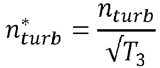
- Accordingly, a normalized turbine speed may be calculated from a quotient of the turbine speed and a square root of the pre turbine temperature. A pre turbine temperature may be measured directly or derived, e.g. from the turbine power and a measured post turbine temperature.
- In
figure 2 , the turbine power is estimated by equating it to the calculated compressor power. It was found that for a constant VGT position, normalized turbine speed and heat capacity ratio, an approximately linear relation between turbine expansion ratio and normalized turbine power exists. This relationship is used in a further step (III), wherein an expansion ratio is derived from a linear relation between the expansion ratio and the calculated normalized turbine power. A pre turbine pressure (p 3) can then be derived from a post turbine pressure (p 4), used as input, and a calculated expansion ratio, as will be further illustrated with reference tofigure 3 . - A back pressure valve (BPV) may be present in the system, in which case a post turbine pressure can be derived, by calculating a pressure difference based on a back pressure valve position, exhaust gas mass flow, and BPV outlet pressure and temperature. Thus, in a pre turbine pressure estimation algorithm, the estimated normalized turbine power is used, together with VGT position, turbine speed, heat capacity ratio and post turbine pressure to estimate the pre turbine pressure. Accordingly, a pressure monitor is provided, arranged to calculate a pre turbine pressure (p 3), wherein the pressure monitor is programmed to:
- ∘ derive a normalized turbine speed, normalized for a pre turbine temperature, and a heat capacity ratio of exhaust gas before the turbine as first inputs;
- ∘ determine a turbine power normalizing factor as a second input;
- ∘ determine an actual turbocompressor power value as a third input;
- ∘ derive, for said first inputs, a linear relation between a turbine expansion ratio and a turbine power value normalized by the second input;
- ∘ equate the turbine power value to the actual turbocompressor power; thereby deriving the pre turbine pressure from said linear relation, as an output.
- In a preferred embodiment, the turbine may be a variable geometry turbine having an adjustable turbine nozzle position or by vanes that can be adjusted; wherein said linear relation is further derived for each turbine position.
- In
figure 3 exemplary linear relations are given that may be derived by plotting the turbine expansion ratio relative to the normalized turbine power. For a constant VGT position and normalized turbine speed, an approximately linear relation between the turbine expansion ratio and normalized turbine power exists. - This means, the normalized turbine power can be estimated using a linear line. A line can be described using a constant and an offset. For each VGT position, normalized turbine speed and heat capacity ratio, a different constant and offset are needed to estimate the normalized turbine power, so:



- From this relation, the pre turbine pressure (p 3) can be estimated.

- Advantage of this method, besides the high accuracy, is that the pre turbine estimate is less sensitive to exhaust mass flow deviations. Also, the dependency on heat capacity ratio is relatively minor, so it can be decided to omit this input and have a 2D C0 and C1 map, which is easy to implement.
- The disclosed method can be used to estimate the exhaust manifold pressure, using the turbine power, post turbine pressure, pre turbine temperature, turbine speed, exhaust gas gas properties, and in case of a variable geometry turbo, the VGT position.
- The model can for example be used for a plausibility check of a pre turbine pressure sensor, or as a replacement.
- Direct model inputs:
- nturb nturb Turbine speed
- ∘ May be measured with a turbine speed sensor or estimated using a compressor model
- p 4 Post turbine pressure
- ∘ May be measured with a pressure sensor or estimated based on a pressure sensor further downstream in the air path, in combination with a pressure drop model of the intermediate air path (using e.g., the exhaust gas mass flow and the temperature of the exhaust gas)
- Pturb Turbine power
- ∘ May be estimated from the temperature before (T 3) and after the turbine (T 4), the exhaust gas mass flow (ṁexh ) and the heat capacity at constant pressure (cp,exh ):

- ∘ May be estimated from the temperature before (T 3) and after the turbine (T 4), the exhaust gas mass flow (ṁexh ) and the heat capacity at constant pressure (cp,exh ):
- The temperature after the turbine may be measured using a temperature sensor (but might also be estimated based on a temperature sensor further downstream in the air path). The exhaust gas flow can be measured directly or estimated based on the fresh air flow.
- ∘ According to the invention, the turbine power may also be estimated based on the compressor power (Pcomp ), possibly also taking the estimated power lost due to turbo inertia (PI,turbo ) and the estimated power lost to mechanical losses (e.g. friction) (Ploss ) into account:

- The estimated compressor power can be based on the fresh air flow (ṁair ), the heat capacity at constant pressure of the intake air (cp,air ), the pre compressor temperature (T 1) and the compressor power factor (Fcomp ):

- The pre compressor temperature can be measured (but can also be estimated based on a temperature further upstream in the air path). The intake air heat capacity at constant pressure can be estimated based on the intake air composition and the temperature before the compressor, or selected as a constant. The fresh air flow can either be estimated or measured using an air flow meter. The compressor power factor can be determined in several ways, e.g.:
- ▪ Based on a lookup table based on (normalized) turbo speed (


- Normalization is optional and can be done in several ways. For turbo speed, this can for example be based on inlet conditions (


- ▪ Based on the temperature before (T 1) and after the compressor (Tacomp ):
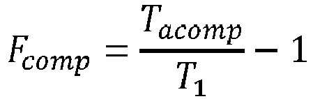
- The temperature at the compressor inlet can be measured but can also be estimated based on a temperature further upstream in the air path. The temperature after the compressor can be measured, or estimated based on the compressor efficiency, pressure ratio and turbine speed
- ▪ Based on the pre compressor pressure (p 1), the post compressor pressure (pacomp ), the heat capacity ratio of intake air (γair ), and the compressor efficiency (ηcomp ):

- The pressure before the compressor (p 1) can be measured or estimated based on a pressure sensor further upstream in the air path. The pressure after the compressor can be measured or estimated based on a pressure sensor further downstream in the air path. The heat capacity ratio of intake air can be estimated based on the intake air gas composition and the temperature before the compressor, or selected as a constant. The compressor efficiency can be determined from a 2D lookup table, using at least 2 of the following signals: pressure ratio, fresh air mass flow, or turbine speed. Fresh air mass flow and turbine speed can be normalized to provide robustness against deviating compressor inlet conditions.
- T 3 Pre turbine temperature (often equal to exhaust manifold temperature)
- ∘ May be measured with a temperature sensor or estimated based on the turbine power (Pturb ), the exhaust gas mass flow (ṁexh ), the heat capacity at constant pressure of the exhaust gas (cp,exh ), and the temperature after the turbine (T 4):

- ∘ May be measured with a temperature sensor or estimated based on the turbine power (Pturb ), the exhaust gas mass flow (ṁexh ), the heat capacity at constant pressure of the exhaust gas (cp,exh ), and the temperature after the turbine (T 4):
- The temperature after the turbine is usually measured using a temperature sensor (but might also be estimated based on a temperature sensor further downstream in the air path). The exhaust gas flow can be estimated based on the fresh air flow or measured directly. The turbine power can be determined using the compressor power (as described above). For the estimation of the pre turbine pressure, the compressor power estimate may be based on the compressor pressure ratio:

- VGT VGT position
- ∘ This is an actuator value that is prescribed. If an engine with a fixed geometry turbo is used, the dependency on VGT position can be discarded.
- γexh Heat capacity ratio of the exhaust gas before the turbine
- ∘ May be estimated based on the exhaust gas composition and the temperature before the turbine or selected as a constant
- cp
exh Heat capacity at constant pressure of the exhaust gas before the turbine- ∘ May be estimated based on the exhaust gas composition and the temperature before the turbine or selected as a constant
- Additional explanation of indirect model inputs:
- ṁexh Exhaust gas mass flow
- ∘ May be measured using a flow meter in the exhaust path or estimated using fresh air mass flow, fuel flow, and blowby

- ∘ May be measured using a flow meter in the exhaust path or estimated using fresh air mass flow, fuel flow, and blowby
- ṁair Fresh air mass flow
- ∘ May be measured using a flow meter in the intake path or estimated using e.g.:
- ▪ A compressor model;
- ▪ The pressure drop over the air filter
- ▪ An engine out O2 sensor
- ▪ A total engine flow (for example estimated using a volumetric efficiency based model). If the engine contains an EGR path, the EGR flow (e.g. determined using a model based on the EGR valve position and pressure drop over the EGR path, a Venturi in combination with a sensor measuring the pressure drop between the Venturi in-or outlet and the Venturi throat, or a flow measurement device) may be subtracted from the engine flow
- ▪ A fresh air flow measurement device
- ∘ May be measured using a flow meter in the intake path or estimated using e.g.:
- Other variations to the disclosed embodiments can be understood and by those skilled in the art in practicing the claimed invention, from a study of the drawings, the disclosure, and the appended claims. In the claims, the word "comprising" does not exclude other elements or steps, and the indefinite article "a" or "an" does not exclude a plurality. A single unit may fulfil the functions of several items recited in the claims. The mere fact that certain measures are recited in mutually different dependent claims does not indicate that a combination of these measured cannot be used to advantage. Any reference signs in the claims should not be construed as limiting the scope.
Claims (7)
- An internal combustion engine comprising:- an inlet manifold providing compressed inlet air into a plurality of cylinders;- an exhaust manifold for exhausting combusted gases from the plurality of cylinders;- a turbine provided in an exhaust channel coupled to the exhaust manifold;- a turbocompressor provided in an inlet channel coupled to the inlet manifold;- a pressure monitor arranged to calculate a pre turbine pressure (p 3), wherein the pressure monitor is programmed to:∘ derive a normalized turbine speed, normalized for a pre turbine temperature, and a heat capacity ratio of exhaust gas before the turbine as first inputs;∘ determine a turbine power normalizing factor as a second input;∘ determine an actual turbocompressor power value as a third input;∘ derive, for said first inputs, a linear relation between a turbine expansion ratio and a turbine power value normalized by the second input;∘ equate the turbine power value to the actual turbocompressor power; thereby deriving the pre turbine pressure from said linear relation, as an output.
- An internal combustion engine according to claim 1, wherein the turbine power normalizing factor is a product of post turbine pressure; heat capacity at constant pressure of the exhaust gas and square root of the pre turbine temperature.
- An internal combustion engine according to any preceding claim, wherein the normalized turbine speed is calculated from a quotient of the turbine speed and a square root of the pre turbine temperature.
- An internal combustion engine according to any preceding claim, wherein the pre turbine temperature is measured directly or derived from the turbine power and a post turbine temperature.
- An internal combustion engine according to any preceding claim, wherein the turbine is a variable geometry turbine having an adjustable turbine nozzle position; wherein said linear relation is further derived for each turbine nozzle position.
- An internal combustion engine according to any preceding claim, wherein the turbocompressor power is derived from a product of compressor mass flow; heat capacity at constant pressure of intake air; pre compressor temperature; and a power factor, based on a compressor mass flow normalized for pre compressor pressure and temperature, and a turbo speed normalized for pre compressor temperature.
- A method for monitoring a pre turbine pressure of in internal combustion engine comprising a turbine provided in an exhaust channel coupled to an exhaust manifold and a turbocompressor provided in an inlet channel coupled to an inlet manifold of the internal combustion engine; the method comprising∘ deriving a turbine speed, normalized for a pre turbine temperature, and a heat capacity ratio of exhaust gas before the turbine as first inputs;∘ determining a turbine power normalizing factor as a second input;∘ determine an actual turbocompressor power value as a third input;∘ derive, for said first inputs, a linear relation between a turbine expansion ratio and a turbine power value normalized by the second input;∘ equate the turbine power value to the actual turbocompressor power; thereby deriving the pre turbine pressure from said linear relation, as an output.
Applications Claiming Priority (1)
| Application Number | Priority Date | Filing Date | Title |
|---|---|---|---|
| NL2031951A NL2031951B1 (en) | 2022-05-20 | 2022-05-20 | Engine pre turbine pressure monitoring system |
Publications (3)
| Publication Number | Publication Date |
|---|---|
| EP4279729A1 true EP4279729A1 (en) | 2023-11-22 |
| EP4279729C0 EP4279729C0 (en) | 2025-01-29 |
| EP4279729B1 EP4279729B1 (en) | 2025-01-29 |
Family
ID=83188340
Family Applications (1)
| Application Number | Title | Priority Date | Filing Date |
|---|---|---|---|
| EP23174287.5A Active EP4279729B1 (en) | 2022-05-20 | 2023-05-19 | Engine pre turbine pressure monitoring system |
Country Status (3)
| Country | Link |
|---|---|
| US (1) | US12422338B2 (en) |
| EP (1) | EP4279729B1 (en) |
| NL (1) | NL2031951B1 (en) |
Cited By (1)
| Publication number | Priority date | Publication date | Assignee | Title |
|---|---|---|---|---|
| EP4571088A1 (en) * | 2023-12-15 | 2025-06-18 | Volvo Truck Corporation | Internal combustion engine system |
Families Citing this family (1)
| Publication number | Priority date | Publication date | Assignee | Title |
|---|---|---|---|---|
| US12345220B1 (en) * | 2023-12-29 | 2025-07-01 | Saudi Arabian Oil Company | Air-handling system for fuel-efficient low load thermal promotion and high load operation for heavy duty engines |
Citations (3)
| Publication number | Priority date | Publication date | Assignee | Title |
|---|---|---|---|---|
| WO2008024590A2 (en) * | 2006-08-22 | 2008-02-28 | Gm Global Technology Operations, Inc. | Method and apparatus for estimating exhaust pressure of an internal combustion engine |
| FR3014145A1 (en) * | 2013-12-02 | 2015-06-05 | Renault Sa | METHOD FOR DETERMINING THE GAS PRESSURE IN THE UPSTREAM OF A SUPERCONTACT TURBINE OF AN INTERNAL COMBUSTION ENGINE AND A SYSTEM FOR SERVING SUCH A METHOD |
| US20150345377A1 (en) * | 2014-06-03 | 2015-12-03 | GM Global Technology Operations LLC | Turbine expansion ratio estimation for model-based boost control |
Family Cites Families (4)
| Publication number | Priority date | Publication date | Assignee | Title |
|---|---|---|---|---|
| US6658364B2 (en) * | 2001-01-12 | 2003-12-02 | Delphi Technologies, Inc. | Method of estimating gas pressure in an engine exhaust manifold |
| ITTO20010615A1 (en) * | 2001-06-26 | 2002-12-26 | Iveco Motorenforschung Ag | ENDOTHERMAL-TURBOCHARGER ENGINE UNIT FOR A VEHICLE, IN PARTICULAR FOR AN INDUSTRIAL VEHICLE, WITH CONTROL OF THE POWER OF THE |
| FR2953253B1 (en) * | 2009-12-02 | 2012-12-14 | Renault Sa | METHOD FOR CONTROLLING TWO STAGE SUPERIORING OF FIXED GEOMETRY TURBOCHARGERS WITH DYNAMIC ESTIMATOR AND LIMITING THE PRESSURE BEFORE TURBINE |
| FR3033641B1 (en) * | 2015-03-11 | 2019-06-14 | Renault S.A.S | METHOD FOR DETERMINING THE PRESSURE BEFORE THE TURBINE OF A TURBOCHARGER OF AN INTERNAL COMBUSTION ENGINE OF A MOTOR VEHICLE. |
-
2022
- 2022-05-20 NL NL2031951A patent/NL2031951B1/en active
-
2023
- 2023-04-26 US US18/307,169 patent/US12422338B2/en active Active
- 2023-05-19 EP EP23174287.5A patent/EP4279729B1/en active Active
Patent Citations (3)
| Publication number | Priority date | Publication date | Assignee | Title |
|---|---|---|---|---|
| WO2008024590A2 (en) * | 2006-08-22 | 2008-02-28 | Gm Global Technology Operations, Inc. | Method and apparatus for estimating exhaust pressure of an internal combustion engine |
| FR3014145A1 (en) * | 2013-12-02 | 2015-06-05 | Renault Sa | METHOD FOR DETERMINING THE GAS PRESSURE IN THE UPSTREAM OF A SUPERCONTACT TURBINE OF AN INTERNAL COMBUSTION ENGINE AND A SYSTEM FOR SERVING SUCH A METHOD |
| US20150345377A1 (en) * | 2014-06-03 | 2015-12-03 | GM Global Technology Operations LLC | Turbine expansion ratio estimation for model-based boost control |
Non-Patent Citations (2)
| Title |
|---|
| FREDRIKSSON J ET AL: "Estimating exhaust manifold pressure in a turbocharged diesel engine", PROCEEDINGS OF THE 2002 IEEE INTERNATIONAL CONFERENCE ON CONTROL APPLICATIONS. CCA 2002. GLASCOW, SCOTLAND, U.K. , SEPT. 18 - 20, 2002; [IEEE INTERNATIONAL CONFERENCE ON CONTROL APPLICATIONS], NEW YORK, NY : IEEE, US, vol. 2, 18 September 2002 (2002-09-18), pages 701 - 706, XP010606059, ISBN: 978-0-7803-7386-0, DOI: 10.1109/CCA.2002.1038686 * |
| WANG ET AL: "Exhaust Backpressure Estimation for an Internal Combustion Engine with a Variable Geometry Turbo Charger", SAE 2010 COMMERCIAL VEHICLE ENGINEERING CONGRESS SAE TECHNICAL PAPERS, SAE INTERNATIONAL, US, 2009, XP002787767, ISSN: 0148-7191, DOI: 10.4271/2009-01-0732 * |
Cited By (2)
| Publication number | Priority date | Publication date | Assignee | Title |
|---|---|---|---|---|
| EP4571088A1 (en) * | 2023-12-15 | 2025-06-18 | Volvo Truck Corporation | Internal combustion engine system |
| US12372040B2 (en) | 2023-12-15 | 2025-07-29 | Volvo Truck Corporation | Internal combustion engine system |
Also Published As
| Publication number | Publication date |
|---|---|
| NL2031951B1 (en) | 2023-11-27 |
| US12422338B2 (en) | 2025-09-23 |
| US20230384183A1 (en) | 2023-11-30 |
| EP4279729C0 (en) | 2025-01-29 |
| EP4279729B1 (en) | 2025-01-29 |
Similar Documents
| Publication | Publication Date | Title |
|---|---|---|
| EP4279729B1 (en) | Engine pre turbine pressure monitoring system | |
| US10041427B2 (en) | Sensor output value estimation device | |
| RU2604689C2 (en) | Method and system of diagnostics of power plant with two multi-stage turbo compressors | |
| US20130042609A1 (en) | Unit for estimating the rotational speed of a turbocharger and system and method for controlling an internal combustion engine with a turbocharger | |
| US20090113896A1 (en) | Control apparatus and method for gas-turbine engine | |
| EP2615283A1 (en) | A method and observer for determining the exhaust manifold temperature in a turbocharged engine | |
| CN113361040B (en) | Combustion chamber outlet temperature evaluation method under complete engine condition | |
| US9249738B2 (en) | Method for automatic closed-loop control of one or more combustion temperatures in a gas turbine installation and method for determination of the water content in the working fluid of a gas turbine installation | |
| US11643977B2 (en) | Gas turbine control device, gas turbine control method, and program | |
| US20210293193A1 (en) | System and method for estimating turbo speed of an engine | |
| KR102384313B1 (en) | Method and device for checking a pressure-based mass flow sensor in an air supply system for an internal combustion engine | |
| US20200291807A1 (en) | Method and device for measuring the flow rate of cooling air in a turbomachine casing | |
| US10451491B2 (en) | System and method to determine total air temperature from turbofan bypass flow temperature | |
| WO2007136449A1 (en) | System and method for monitoring boost leak | |
| JP2015524888A (en) | Method and system for diagnosing intake air taken into an internal combustion engine of an automobile | |
| CN110318864B (en) | Altitude-based two-stage supercharging system opening correction method and two-stage supercharging system | |
| CN110220637A (en) | Method for estimating the compressor inlet pressure of turbocharger | |
| US20170122231A1 (en) | Method for determining atmospheric pressure during the operation, in a partial load state, of a turbocharged engine | |
| US20150000297A1 (en) | Method for determining at least one firing temperature for controlling a gas turbine and gas turbine for performing the method | |
| RU2649715C1 (en) | Method of aviation bypass turbojet engine with flows mixing in-flight diagnostics | |
| CN102011641A (en) | Method of operating turbo charger and control | |
| US10054533B2 (en) | Method for estimating pressure loss of air cleaner and device for estimating pressure loss of air cleaner | |
| Whitehouse et al. | Estimating the effects of altitude, ambient temperature and turbocharger match on engine performance | |
| JP2014034948A (en) | Egr rate estimating device and egr rate estimating method of internal combustion engine | |
| JP2018146270A (en) | Flow measurement system |
Legal Events
| Date | Code | Title | Description |
|---|---|---|---|
| PUAI | Public reference made under article 153(3) epc to a published international application that has entered the european phase |
Free format text: ORIGINAL CODE: 0009012 |
|
| STAA | Information on the status of an ep patent application or granted ep patent |
Free format text: STATUS: THE APPLICATION HAS BEEN PUBLISHED |
|
| AK | Designated contracting states |
Kind code of ref document: A1 Designated state(s): AL AT BE BG CH CY CZ DE DK EE ES FI FR GB GR HR HU IE IS IT LI LT LU LV MC ME MK MT NL NO PL PT RO RS SE SI SK SM TR |
|
| STAA | Information on the status of an ep patent application or granted ep patent |
Free format text: STATUS: REQUEST FOR EXAMINATION WAS MADE |
|
| 17P | Request for examination filed |
Effective date: 20240517 |
|
| RBV | Designated contracting states (corrected) |
Designated state(s): AL AT BE BG CH CY CZ DE DK EE ES FI FR GB GR HR HU IE IS IT LI LT LU LV MC ME MK MT NL NO PL PT RO RS SE SI SK SM TR |
|
| GRAP | Despatch of communication of intention to grant a patent |
Free format text: ORIGINAL CODE: EPIDOSNIGR1 |
|
| STAA | Information on the status of an ep patent application or granted ep patent |
Free format text: STATUS: GRANT OF PATENT IS INTENDED |
|
| INTG | Intention to grant announced |
Effective date: 20240924 |
|
| GRAS | Grant fee paid |
Free format text: ORIGINAL CODE: EPIDOSNIGR3 |
|
| GRAA | (expected) grant |
Free format text: ORIGINAL CODE: 0009210 |
|
| STAA | Information on the status of an ep patent application or granted ep patent |
Free format text: STATUS: THE PATENT HAS BEEN GRANTED |
|
| AK | Designated contracting states |
Kind code of ref document: B1 Designated state(s): AL AT BE BG CH CY CZ DE DK EE ES FI FR GB GR HR HU IE IS IT LI LT LU LV MC ME MK MT NL NO PL PT RO RS SE SI SK SM TR |
|
| REG | Reference to a national code |
Ref country code: GB Ref legal event code: FG4D |
|
| REG | Reference to a national code |
Ref country code: CH Ref legal event code: EP |
|
| REG | Reference to a national code |
Ref country code: DE Ref legal event code: R096 Ref document number: 602023001851 Country of ref document: DE |
|
| REG | Reference to a national code |
Ref country code: IE Ref legal event code: FG4D |
|
| U01 | Request for unitary effect filed |
Effective date: 20250228 |
|
| U07 | Unitary effect registered |
Designated state(s): AT BE BG DE DK EE FI FR IT LT LU LV MT NL PT RO SE SI Effective date: 20250310 |
|
| U20 | Renewal fee for the european patent with unitary effect paid |
Year of fee payment: 3 Effective date: 20250401 |
|
| PG25 | Lapsed in a contracting state [announced via postgrant information from national office to epo] |
Ref country code: RS Free format text: LAPSE BECAUSE OF FAILURE TO SUBMIT A TRANSLATION OF THE DESCRIPTION OR TO PAY THE FEE WITHIN THE PRESCRIBED TIME-LIMIT Effective date: 20250429 |
|
| PG25 | Lapsed in a contracting state [announced via postgrant information from national office to epo] |
Ref country code: PL Free format text: LAPSE BECAUSE OF FAILURE TO SUBMIT A TRANSLATION OF THE DESCRIPTION OR TO PAY THE FEE WITHIN THE PRESCRIBED TIME-LIMIT Effective date: 20250129 |
|
| PG25 | Lapsed in a contracting state [announced via postgrant information from national office to epo] |
Ref country code: ES Free format text: LAPSE BECAUSE OF FAILURE TO SUBMIT A TRANSLATION OF THE DESCRIPTION OR TO PAY THE FEE WITHIN THE PRESCRIBED TIME-LIMIT Effective date: 20250129 |
|
| PG25 | Lapsed in a contracting state [announced via postgrant information from national office to epo] |
Ref country code: IS Free format text: LAPSE BECAUSE OF FAILURE TO SUBMIT A TRANSLATION OF THE DESCRIPTION OR TO PAY THE FEE WITHIN THE PRESCRIBED TIME-LIMIT Effective date: 20250529 Ref country code: NO Free format text: LAPSE BECAUSE OF FAILURE TO SUBMIT A TRANSLATION OF THE DESCRIPTION OR TO PAY THE FEE WITHIN THE PRESCRIBED TIME-LIMIT Effective date: 20250429 |
|
| PG25 | Lapsed in a contracting state [announced via postgrant information from national office to epo] |
Ref country code: HR Free format text: LAPSE BECAUSE OF FAILURE TO SUBMIT A TRANSLATION OF THE DESCRIPTION OR TO PAY THE FEE WITHIN THE PRESCRIBED TIME-LIMIT Effective date: 20250129 |
|
| PG25 | Lapsed in a contracting state [announced via postgrant information from national office to epo] |
Ref country code: GR Free format text: LAPSE BECAUSE OF FAILURE TO SUBMIT A TRANSLATION OF THE DESCRIPTION OR TO PAY THE FEE WITHIN THE PRESCRIBED TIME-LIMIT Effective date: 20250430 |
|
| PG25 | Lapsed in a contracting state [announced via postgrant information from national office to epo] |
Ref country code: SM Free format text: LAPSE BECAUSE OF FAILURE TO SUBMIT A TRANSLATION OF THE DESCRIPTION OR TO PAY THE FEE WITHIN THE PRESCRIBED TIME-LIMIT Effective date: 20250129 |
|
| PG25 | Lapsed in a contracting state [announced via postgrant information from national office to epo] |
Ref country code: CZ Free format text: LAPSE BECAUSE OF FAILURE TO SUBMIT A TRANSLATION OF THE DESCRIPTION OR TO PAY THE FEE WITHIN THE PRESCRIBED TIME-LIMIT Effective date: 20250129 |
|
| PG25 | Lapsed in a contracting state [announced via postgrant information from national office to epo] |
Ref country code: SK Free format text: LAPSE BECAUSE OF FAILURE TO SUBMIT A TRANSLATION OF THE DESCRIPTION OR TO PAY THE FEE WITHIN THE PRESCRIBED TIME-LIMIT Effective date: 20250129 |
|
| PLBE | No opposition filed within time limit |
Free format text: ORIGINAL CODE: 0009261 |
|
| STAA | Information on the status of an ep patent application or granted ep patent |
Free format text: STATUS: NO OPPOSITION FILED WITHIN TIME LIMIT |
|
| 26N | No opposition filed |
Effective date: 20251030 |
|
| PG25 | Lapsed in a contracting state [announced via postgrant information from national office to epo] |
Ref country code: MC Free format text: LAPSE BECAUSE OF FAILURE TO SUBMIT A TRANSLATION OF THE DESCRIPTION OR TO PAY THE FEE WITHIN THE PRESCRIBED TIME-LIMIT Effective date: 20250129 |
|
| PG25 | Lapsed in a contracting state [announced via postgrant information from national office to epo] |
Ref country code: IE Free format text: LAPSE BECAUSE OF NON-PAYMENT OF DUE FEES Effective date: 20250519 |
|
| U20 | Renewal fee for the european patent with unitary effect paid |
Year of fee payment: 4 Effective date: 20260527 |
|
| PG25 | Lapsed in a contracting state [announced via postgrant information from national office to epo] |
Ref country code: CY Free format text: LAPSE BECAUSE OF FAILURE TO SUBMIT A TRANSLATION OF THE DESCRIPTION OR TO PAY THE FEE WITHIN THE PRESCRIBED TIME-LIMIT Effective date: 20250129 |