EP4279712A2 - Aperture pattern for gas turbine engine component with integral alignment feature - Google Patents
Aperture pattern for gas turbine engine component with integral alignment feature Download PDFInfo
- Publication number
- EP4279712A2 EP4279712A2 EP23174033.3A EP23174033A EP4279712A2 EP 4279712 A2 EP4279712 A2 EP 4279712A2 EP 23174033 A EP23174033 A EP 23174033A EP 4279712 A2 EP4279712 A2 EP 4279712A2
- Authority
- EP
- European Patent Office
- Prior art keywords
- apertures
- intergroup
- component
- fastener apertures
- fastener
- Prior art date
- Legal status (The legal status is an assumption and is not a legal conclusion. Google has not performed a legal analysis and makes no representation as to the accuracy of the status listed.)
- Pending
Links
Images





Classifications
-
- F—MECHANICAL ENGINEERING; LIGHTING; HEATING; WEAPONS; BLASTING
- F01—MACHINES OR ENGINES IN GENERAL; ENGINE PLANTS IN GENERAL; STEAM ENGINES
- F01D—NON-POSITIVE DISPLACEMENT MACHINES OR ENGINES, e.g. STEAM TURBINES
- F01D25/00—Component parts, details, or accessories, not provided for in, or of interest apart from, other groups
- F01D25/24—Casings; Casing parts, e.g. diaphragms, casing fastenings
- F01D25/243—Flange connections; Bolting arrangements
-
- F—MECHANICAL ENGINEERING; LIGHTING; HEATING; WEAPONS; BLASTING
- F01—MACHINES OR ENGINES IN GENERAL; ENGINE PLANTS IN GENERAL; STEAM ENGINES
- F01D—NON-POSITIVE DISPLACEMENT MACHINES OR ENGINES, e.g. STEAM TURBINES
- F01D25/00—Component parts, details, or accessories, not provided for in, or of interest apart from, other groups
- F01D25/28—Supporting or mounting arrangements, e.g. for turbine casing
-
- F—MECHANICAL ENGINEERING; LIGHTING; HEATING; WEAPONS; BLASTING
- F05—INDEXING SCHEMES RELATING TO ENGINES OR PUMPS IN VARIOUS SUBCLASSES OF CLASSES F01-F04
- F05D—INDEXING SCHEME FOR ASPECTS RELATING TO NON-POSITIVE-DISPLACEMENT MACHINES OR ENGINES, GAS-TURBINES OR JET-PROPULSION PLANTS
- F05D2230/00—Manufacture
- F05D2230/60—Assembly methods
- F05D2230/64—Assembly methods using positioning or alignment devices for aligning or centring, e.g. pins
-
- F—MECHANICAL ENGINEERING; LIGHTING; HEATING; WEAPONS; BLASTING
- F05—INDEXING SCHEMES RELATING TO ENGINES OR PUMPS IN VARIOUS SUBCLASSES OF CLASSES F01-F04
- F05D—INDEXING SCHEME FOR ASPECTS RELATING TO NON-POSITIVE-DISPLACEMENT MACHINES OR ENGINES, GAS-TURBINES OR JET-PROPULSION PLANTS
- F05D2230/00—Manufacture
- F05D2230/60—Assembly methods
- F05D2230/64—Assembly methods using positioning or alignment devices for aligning or centring, e.g. pins
- F05D2230/644—Assembly methods using positioning or alignment devices for aligning or centring, e.g. pins for adjusting the position or the alignment, e.g. wedges or eccenters
-
- F—MECHANICAL ENGINEERING; LIGHTING; HEATING; WEAPONS; BLASTING
- F05—INDEXING SCHEMES RELATING TO ENGINES OR PUMPS IN VARIOUS SUBCLASSES OF CLASSES F01-F04
- F05D—INDEXING SCHEME FOR ASPECTS RELATING TO NON-POSITIVE-DISPLACEMENT MACHINES OR ENGINES, GAS-TURBINES OR JET-PROPULSION PLANTS
- F05D2230/00—Manufacture
- F05D2230/70—Disassembly methods
-
- F—MECHANICAL ENGINEERING; LIGHTING; HEATING; WEAPONS; BLASTING
- F05—INDEXING SCHEMES RELATING TO ENGINES OR PUMPS IN VARIOUS SUBCLASSES OF CLASSES F01-F04
- F05D—INDEXING SCHEME FOR ASPECTS RELATING TO NON-POSITIVE-DISPLACEMENT MACHINES OR ENGINES, GAS-TURBINES OR JET-PROPULSION PLANTS
- F05D2240/00—Components
- F05D2240/10—Stators
- F05D2240/14—Casings or housings protecting or supporting assemblies within
-
- F—MECHANICAL ENGINEERING; LIGHTING; HEATING; WEAPONS; BLASTING
- F05—INDEXING SCHEMES RELATING TO ENGINES OR PUMPS IN VARIOUS SUBCLASSES OF CLASSES F01-F04
- F05D—INDEXING SCHEME FOR ASPECTS RELATING TO NON-POSITIVE-DISPLACEMENT MACHINES OR ENGINES, GAS-TURBINES OR JET-PROPULSION PLANTS
- F05D2260/00—Function
- F05D2260/30—Retaining components in desired mutual position
- F05D2260/31—Retaining bolts or nuts
Definitions
- This disclosure relates generally to a gas turbine engine and, more particularly, to a mechanical joint between engine components.
- a stationary structure for a gas turbine engine may include a plurality of engine cases connected together at a mechanical joint such as a bolted flange joint.
- a mechanical joint such as a bolted flange joint.
- one or both of the engine cases may include an alignment feature.
- Various types of alignment features are known in the art. While these known alignment features have various benefits, there is still room in the art for improvement. In particular, there is a need in the art for a mechanical joint between engine components with integral alignment to reduce stationary structure complexity and increase stationary structure strength.
- a structure for a gas turbine engine.
- This structure includes a first engine component, a second engine component and a plurality of fasteners.
- the first engine component includes a plurality of component apertures equally spaced circumferentially about an axis.
- the component apertures include a plurality of first fastener apertures and a plurality of intergroup apertures.
- the first fastener apertures are arranged into a plurality of groups including a first group and a second group.
- the first group is formed by N 1 -number of the first fastener apertures.
- the second group is formed by N 2 -number of the first fastener apertures where the N 2 -number is different than the N 1 -number.
- Each of the intergroup apertures is disposed circumferentially between and adjacent a respective circumferentially neighboring pair of the groups.
- the second engine component includes a surface and a plurality of second fastener apertures. The surface axially engages the first engine component and covers the intergroup apertures.
- the fasteners attach the first engine component and the second engine component together. Each of the fasteners is mated with a respective one of the first fastener apertures and a respective one of the second fastener apertures.
- this structure includes a first engine component, a second engine component and a plurality of fasteners.
- the first engine component includes a first component mount and a plurality of component apertures arranged circumferentially about an axis.
- the first component mount extends circumferentially about the axis.
- Each of the component apertures extends axially through the first component mount.
- the component apertures include a plurality of first fastener apertures and a spacer aperture. A first of the first fastener apertures is circumferentially between and adjacent a second of the first fastener apertures and the spacer aperture.
- a circumferential spacing between the first of the first fastener apertures and the second of the first fastener apertures is equal to a circumferential spacing between the first of the first fastener apertures and the spacer aperture.
- the second engine component includes a surface and a plurality of second fastener apertures. The surface circumferentially and radially overlaps the spacer aperture.
- the fasteners attach the first engine component and the second engine component together. Each of the fasteners are mated with a respective one of the first fastener apertures and a respective one of the second fastener apertures.
- this structure includes a first engine component, a second engine component and a plurality of fasteners.
- the first engine component includes a plurality of component apertures equally spaced circumferentially about an axis.
- the component apertures include a plurality of first fastener apertures and a plurality of intergroup apertures.
- the first fastener apertures are arranged into a plurality of groups including a first group and a second group.
- the first group is formed by N 1 -number of the first fastener apertures.
- the second group is formed by N 2 -number of the first fastener apertures where the N 2 -number is different than the N 1 -number.
- Each of the intergroup apertures is disposed circumferentially between and adjacent a respective circumferentially neighboring pair of the groups. Each of the intergroup apertures is configured to be empty during operation of the gas turbine engine.
- the second engine component includes a plurality of second fastener apertures. The fasteners attach the first engine component and the second engine component together. Each of the fasteners is mated with a respective one of the first fastener apertures and a respective one of the second fastener apertures.
- the spacer aperture may be circumferentially between and adjacent the first of the first fastener apertures and a third of the first fastener apertures.
- the circumferential spacing between the first of the first fastener apertures and the spacer aperture may be equal to a circumferential spacing between the spacer aperture and the third of the first fastener apertures.
- the third of the first fastener apertures may be circumferentially between and adjacent the spacer aperture and a fourth of the first fastener apertures.
- the circumferential spacing between the third of the first fastener apertures and the spacer aperture may be equal to a circumferential spacing between the third of the first fastener apertures and the fourth of the first fastener apertures.
- the component apertures may also include a plurality of intergroup apertures.
- the first fastener apertures may be arranged into a plurality of groups including a first group and a second group.
- the first group may be formed by N 1 -number of the first fastener apertures including the first of the first fastener apertures and the second of the first fastener apertures.
- the second group may be formed by N 2 -number of the first fastener apertures where the N 2 -number is different than the N 1 -number.
- Each of the intergroup apertures may be disposed circumferentially between and adjacent a respective circumferentially neighboring pair of the groups.
- the intergroup apertures may include the spacer aperture.
- the first engine component may be configured as an engine case.
- the first engine component may be configured as or otherwise include a mount.
- the mount may extend circumferentially about the axis.
- Each of the component apertures may extend axially through the mount.
- a first of the intergroup apertures may be a threaded aperture.
- a first of the intergroup apertures may be configured to be empty during operation of the gas turbine engine.
- a first of the intergroup apertures may be configured to mate with a tool during disassembly of the structure where the tool threads into the first of the intergroup apertures and presses axially against the surface.
- the N 1 -number may be an even number.
- the N 2 -number may be an odd number.
- the first engine component may be configured with a N T -number of the first fastener apertures.
- the N T -number may be an odd number.
- the groups may also include a third group.
- the third group may be formed by N 3 -number of the first fastener apertures.
- the N 3 -number may be an even number.
- the groups may also include a third group.
- the third group may be formed by N 3 -number of the first fastener apertures.
- the N 3 -number may be different than the N 2 -number.
- the intergroup apertures may include a first intergroup aperture, a second intergroup aperture and a third intergroup aperture.
- the first intergroup aperture may be disposed circumferentially between and adjacent the first group and the second group.
- the second intergroup aperture may be disposed circumferentially between and adjacent the first group and the third group.
- the third intergroup aperture may be disposed circumferentially between and adjacent the second group and the third group.
- the N 3 -number may be equal to the N 1 -number.
- the intergroup apertures may include a first intergroup aperture, a second intergroup and a third intergroup aperture.
- the first intergroup aperture may be X 1 -number of degrees from the second intergroup aperture about the axis.
- the first intergroup aperture may be X 2 -number of degrees from the third intergroup aperture about the axis where the X 2 -number is equal to the X 1 -number.
- the second intergroup aperture may be X 3 -number of degrees from the third intergroup aperture about the axis.
- the X 3 -number may be within plus or minus five degrees of the X 1 -number.
- the present disclosure may include any one or more of the individual features disclosed above and/or below alone or in any combination thereof.
- FIG. 1 schematically illustrates a gas turbine engine 20 for an aircraft.
- This gas turbine engine 20 may be included within a propulsion system for the aircraft.
- the gas turbine engine 20, for example, may be configured as a turbofan gas turbine engine, a turbojet gas turbine engine, a turboprop gas turbine engine or a turboshaft gas turbine engine.
- the gas turbine engine 20 may alternatively be included within an electrical power generation system for the aircraft.
- the gas turbine engine 20, for example, may be configured as an auxiliary power unit (APU).
- APU auxiliary power unit
- the gas turbine engine 20 of the present disclosure is not limited to the foregoing exemplary gas turbine engine types.
- the gas turbine engine 20 may also be configured for non-aircraft applications.
- the gas turbine engine 20 may be configured as a (e.g., ground-based) industrial gas turbine engine for an electrical power generation system.
- the gas turbine engine 20 of the present disclosure may be configured with a single spool, with two spools (e.g., see FIG. 1 ), or with more than two spools depending on, for example, power requirements.
- the gas turbine engine 20 of FIG. 1 includes a mechanical load 22 and a gas turbine engine core 24 configured to drive rotation of the mechanical load 22.
- the mechanical load 22 may be configured as or otherwise include a rotor 26 of the gas turbine engine 20.
- the mechanical load 22, for example, may be configured as a bladed propulsor rotor for the aircraft propulsion system. Examples of the propulsor rotor include, but are not limited to: a fan rotor for the turbofan gas turbine engine; a compressor rotor for the turbojet gas turbine engine; a propeller rotor for the turboprop gas turbine engine; and a helicopter rotor (e.g., a main rotor) for the turboshaft gas turbine engine.
- the mechanical load 22 may alternatively be configured as a generator rotor for the power generation system.
- the engine core 24 of FIG. 1 includes one or more rotating structures 28A and 28B (generally referred to as "28") (e.g., spools) and a stationary structure 30.
- This engine core 24 also includes a plurality of bearings 32 rotatably mounting the rotating structures 28A and 28B to the stationary structure 30.
- the first (e.g., low speed) rotating structure 28A includes a first (e.g., low pressure (LP)) compressor rotor 34A, a first (e.g., low pressure) turbine rotor 36A and a first (e.g., low speed) shaft 38A.
- the first compressor rotor 34A is arranged within and part of a first (e.g., low pressure) compressor section 40A of the engine core 24.
- the first turbine rotor 36A is arranged within and part of a first (e.g., low pressure) turbine section 42A of the engine core 24.
- the first shaft 38A extends axially along a rotational axis 44 between and is connected to the first compressor rotor 34A and the first turbine rotor 36A, where the first rotating structure 28A is rotatable about the rotational axis 44.
- the first rotating structure 28A may also be rotatably coupled to the mechanical load 22 and its rotor 26.
- the mechanical load rotor 26, for example, may be coupled to the first rotating structure 28A through a direct drive coupling.
- This direct drive coupling may be configured as or otherwise include an output shaft 46.
- the mechanical load rotor 26 and the first rotating structure 28A may rotate at a common (e.g., the same) rotational speed.
- the mechanical load rotor 26 may be coupled to the first rotating structure 28A through a geartrain 48 (see dashed line); e.g., a transmission.
- This geartrain 48 may be configured as an epicyclic geartrain. With such a geared coupling, the mechanical load rotor 26 may rotate at a different (e.g., slower) rotational speed than the first rotating structure 28A.
- the second (e.g., high speed) rotating structure 28B includes a second (e.g., high pressure (HP)) compressor rotor 34B, a second (e.g., high pressure) turbine rotor 36B and a second (e.g., high speed) shaft 38B.
- the second compressor rotor 34B is arranged within and part of a second (e.g., high pressure) compressor section 40B of the engine core 24.
- the second turbine rotor 36B is arranged within and part of a second (e.g., high pressure) turbine section 42B of the engine core 24.
- the second shaft 38B extends axially along the rotational axis 44 between and is connected to the second compressor rotor 34B and the second turbine rotor 36B, where the second rotating structure 28B is rotatable about the rotational axis 44.
- the second rotating structure 28B of FIG. 1 and its second shaft 38B axially overlap and circumscribe the first shaft 38A; however, the engine core 24 of the present disclosure is not limited to such an exemplary arrangement.
- the stationary structure 30 is configured to at least partially or completely house the first compressor section 40A, the second compressor section 40B, a combustor section 50 of the engine core 24, the second turbine section 42B and the first turbine section 42A, where the engine sections 40A, 40B, 50, 42B and 42A may be arranged sequentially along the rotational axis 44 between an airflow inlet to the gas turbine engine 20 and an exhaust from the gas turbine engine 20.
- the stationary structure 30 of FIG. 1 axially overlaps and extends circumferentially about (e.g., completely around) the first rotating structure 28A and the second rotating structure 28B.
- core air During operation, air enters the gas turbine engine 20 through the airflow inlet. This air is directed into at least a core flowpath which extends sequentially through the engine sections 40A, 40B, 50, 42B and 42A (e.g., the engine core 24) to the exhaust.
- the air within this core flowpath may be referred to as "core air”.
- the core air is compressed by the first compressor rotor 34A and the second compressor rotor 34B and directed into a combustion chamber 52 of a combustor in the combustor section 50.
- Fuel is injected into the combustion chamber 52 and mixed with the compressed core air to provide a fuel-air mixture.
- This fuel-air mixture is ignited and combustion products thereof flow through and sequentially cause the second turbine rotor 36B and the first turbine rotor 36A to rotate.
- the rotation of the second turbine rotor 36B and the first turbine rotor 36A respectively drive rotation of the second compressor rotor 34B and the first compressor rotor 34A and, thus, compression of the air received from the airflow inlet.
- the mechanical load rotor 26 is configured as the propulsor rotor
- the rotor 26 propels additional air through or outside of the gas turbine engine 20 to provide, for example, a majority of aircraft propulsion system thrust.
- the mechanical load rotor 26 is configured as the generator rotor
- rotation of the rotor 26 facilitates generation of electricity.
- FIGS. 2-4 illustrate a portion of the stationary structure 30.
- This stationary structure 30 includes a plurality of engine components 54 and 56 and a plurality of fastener assemblies 58 coupling the engine components 54 and 56 together at a mechanical joint 60.
- the first engine component 54 may be configured as a tubular engine case for the gas turbine engine 20.
- the first engine component 54 of FIGS. 3 and 4 extends axially along a centerline axis 62 of the stationary structure 30 to an (e.g., forward or aft) axial end 64 of the first engine component 54, which centerline axis 62 may be parallel and/or coaxial with the rotational axis 44.
- This first engine component 54 includes a first component base 66 and a first component mount 68; e.g., a flange and/or a rim.
- the first component base 66 extends axially along the centerline axis 62 to the first component axial end 64.
- the first component base 66 extends circumferentially about (e.g., completely around) the centerline axis 62 (see also FIG. 5 ), which may thereby provide the first component base 66 with a tubular geometry.
- the first component base 66 extends radially between and to an inner side 70 of the first component base 66 and an outer side 72 of the first component base 66.
- the first component mount 68 is connected to (e.g., formed integral with or otherwise bonded to) the first component base 66.
- the first component mount 68 is disposed at (e.g., on, adjacent or proximate) the first component axial end 64.
- the first component mount 68 of FIGS. 3 and 4 extends axially along the centerline axis 62 between and to an axial first side 74 of the first component mount 68 and an axial second side 76 of the first component mount 68, where the first mount second side 76 is slightly recessed axially inward from the first component axial end 64.
- the first mount second side 76 may alternatively be axially aligned with the first component axial end 64 in other embodiments.
- the first component mount 68 extends circumferentially about (e.g., completely around) the centerline axis 62 and the first component base 66 (see also FIG. 5 ), which may thereby provide the first component mount 68 with an annular geometry.
- the first component mount 68 projects radially outward from the first component base 66 at the first base outer side 72 to a radial outer distal end 78 of the first component mount 68.
- the first component mount 68 is configured with a plurality of first component apertures 80A and 80B (generally referred to as "80"). These first component apertures 80 are arranged circumferentially about the centerline axis 62 in an annular array; e.g., a circular array. The first component apertures 80 may also be equally spaced circumferentially about the centerline axis 62. Each circumferentially neighboring pair of the first component apertures 80 of FIG. 6 , for example, is spaced by a common (e.g., the same) circumferential distance 82. This circumferential distance 82 may be measured between centers of the respective circumferentially neighboring first component apertures 80.
- 80 first component apertures 80A and 80B
- Outer peripheries of each of the circumferentially neighboring pairs of the first component apertures 80 may also (or alternatively) be separated by a common circumferential distance 84 where, for example, the first component apertures 80 have a common size 86; e.g., diameter.
- the first component apertures 80A of FIG. 5 include N T -number of first fastener apertures 86A-C (generally referred to as "86") arranged into N FG -number of fastener aperture groups 88A-C (generally referred to as "88"), where the N T -number of first fastener apertures 86 is an odd number of first fastener apertures 86.
- the first component apertures 80B also include N IA -number of intergroup apertures 90A-C (generally referred to as "90") (e.g., spacer apertures and/or jacking apertures) interspersed / interposed with the fastener aperture groups 88, where the N IA -number of intergroup apertures 90 is equal to the N FG -number of fastener aperture groups 88.
- 90 N IA -number of intergroup apertures 90A-C
- each of the first component apertures 80A, 80B extends axially along the centerline axis 62 through the first engine component 54 and its first component mount 68.
- Each first fastener aperture 86 of FIG. 3 is formed as an un-threaded through-hole in a base 92 of the first component mount 68.
- Each first fastener aperture 86 extends axially through the mount base 92 between and to the first mount first side 74 and the first mount second side 76.
- Each intergroup aperture 90 of FIG. 4 may be formed as a threaded bore in a respective insert 94 (e.g., a threaded insert, a jacking insert, etc.) mounted to the mount base 92.
- Each intergroup aperture 90 extends through the respective insert 94 (and thereby through the mount base 92) between and to the first mount second side 76 and an axial distal end 96 of the insert 94, where the insert 94 may project axially out from the first mount first side 74 to its distal end 96.
- the groups 88 of the first fastener apertures 86 include a first group 88A, a second group 88B and a third group 88C.
- the first group 88A of the first fastener apertures 86A is formed by N 1 -number of the first fastener apertures 86A.
- the second group 88B of the first fastener apertures 86B is formed by N 2 -number of the first fastener apertures 86B.
- the third group 88C of the first fastener apertures 86C is formed by N 3 -number of the first fastener apertures 86C.
- the N 1 -number of the first fastener apertures 86A may be the same as (e.g., equal to) the N 3 -number of the first fastener apertures 86C.
- the N 2 -number of the first fastener apertures 86B may be different (e.g., less) than the N 1 -number of the first fastener apertures 86A and/or the N 3 -number of the first fastener apertures 86C.
- the N 1 -number and the N 3 -number of the first fastener apertures 86A and 86C may each be an even number of the first fastener apertures 86A, 86C, and the N 2 -number of the first fastener apertures 86B may be an odd number of the first fastener apertures 86B.
- Each of these fastener aperture groups 88 of FIG. 5 may be configured without any other apertures.
- each intergroup aperture 90 is disposed between a circumferentially neighboring pair of the fastener aperture groups 88. More particularly, each intergroup aperture 90 is disposed between and circumferentially adjacent (A) one of the first fastener apertures 86 in a first of the circumferentially neighboring pair of the fastener aperture groups 88 and (B) one of the first fastener apertures 86 in a second of the circumferentially neighboring pair of the fastener aperture groups 88.
- Each circumferentially neighboring pair of the fastener aperture groups 88 of FIG. 5 may thereby be separated by (e.g., only) a single respective one of the intergroup apertures 90.
- the first intergroup aperture 90A is X 1 -number of degrees from the second intergroup aperture 90B.
- the first intergroup aperture 90A is X 2 -number of degrees from the third intergroup aperture 90C.
- the second intergroup aperture 90B is X 3 -number of degrees from the third intergroup aperture 90C.
- the X 1 -number of degrees may be the same as (e.g., equal to) the X 2 -number of degrees.
- the X 3 -number of degrees may be different (e.g., less) than the X 1 -number of degrees and/or the X 2 -number of degrees. However, the X 3 -number of degrees may be within plus/minus two, five or ten degrees of the X 1 -number of degrees and/or the X 2 -number of degrees, or vice versa. It should be noted, the closer the X 3 -number of degrees is to the X 1 -number of degrees and/or the X 2 -number of degrees, the more evenly loads and/or stresses will be distributed about the first component mount 68 and the j oint 60 of FIGS. 2-4 .
- the second engine component 56 may be configured as a tubular engine case for the gas turbine engine 20.
- the second engine component 56 of FIGS. 3 and 4 extends axially along the centerline axis 62 to an (e.g., aft or forward) axial end 98 of the second engine component 56.
- This second engine component 56 includes a second component base 100 and a second component mount 102; e.g., a flange and/or a rim.
- the second component base 100 extends axially along the centerline axis 62 to the second component axial end 98.
- the second component base 100 extends circumferentially about (e.g., completely around) the centerline axis 62 (see also FIG. 7 ), which may thereby provide the second component base 100 with a tubular geometry.
- the second component base 100 extends radially between and to an inner side 104 of the second component base 100 and an outer side 106 of the second component base 100.
- the second component mount 102 is connected to (e.g., formed integral with or otherwise bonded to) the second component base 100.
- the second component mount 102 is disposed at (e.g., on, adjacent or proximate) the second component axial end 98.
- the second component mount 102 of FIGS. 3 and 4 extends axially along the centerline axis 62 between and to an axial first side 108 of the second component mount 102 and an axial second side 110 of the second component mount 102, where the second mount second side 110 is axially aligned with the second component axial end 98.
- the second mount second side 110 may alternatively be slightly recessed axially inward from the second component axial end 98 in other embodiments.
- the second component mount 102 extends circumferentially about (e.g., completely around) the centerline axis 62 and the first component base 66 (see also FIG. 9 ), which may thereby provide the second component mount 102 with an annular geometry.
- the second component mount 102 projects radially outward from the second component base 100 at the second base outer side 106 to a radial outer distal end 112 of the second component mount 102.
- the second component mount 102 is configured with a plurality of second component apertures 114.
- These second component apertures 114 are arranged circumferentially about the centerline axis 62 in an annular array; e.g., a circular array.
- Each of these second component apertures 114 may be configured as a second fastener aperture 116A, 116B or 116C (generally referred to as "116").
- These second fastener apertures 116 are distributed circumferentially about the centerline axis 62 in a common pattern as the first fastener apertures 86 of FIG. 5 ; e.g., the second fastener apertures 116 and the first fastener apertures 86 have matching / complimentary patterns.
- the second fastener apertures 116 of FIG. 7 are arranged into a plurality of groups 118A-C (generally referred to as "118").
- the first group 118A of the second fastener apertures 116A may match (e.g., have the same number as and complimentary aperture positions to) the first group 88A of the first fastener apertures 86A of FIG. 5 .
- the second group 118B of the second fastener apertures 116B may match the second group 88B of the first fastener apertures 86B of FIG. 5 .
- the third group 118C of the second fastener apertures 116C may match the third group 88C of the first fastener apertures 86C of FIG. 5 .
- first component apertures 80 of FIG. 5 include the intergroup apertures 90
- the groups 118 of the second fastener apertures 116 of FIG. 7 are separated by non-perorated portions of the second component mount 102.
- a respective portion 120A-C (generally referred to as "120") of a surface 122 of the second component mount 102 at its second side 110, for example, is disposed between each circumferentially neighboring pair of the fastener aperture groups 118.
- each portion 120 of the second mount surface 122 extends uninterrupted (e.g., without any apertures, protrusions and/or other interruptions) circumferentially between and to (A) one of the second fastener apertures 116 in a first of the circumferentially neighboring pair of the fastener aperture groups 118 and (B) one of the second fastener apertures 116 in a second of the circumferentially neighboring pair of the fastener aperture groups 118.
- These second mount surface portions 120 are distributed circumferentially about the centerline axis 62 in a common pattern as the intergroup apertures 90 of FIG. 5 .
- each of the second fastener apertures 116 extends axially along the centerline axis 62 through the second engine component 56 and its second component mount 102.
- Each second fastener aperture 116 of FIG. 3 is formed as an un-threaded through-hole in a base 124 of the second component mount 102.
- Each second fastener aperture 116 extends axially through the mount base 124 between and to the second mount first side 108 and the second mount second side 110.
- the first engine component 54 and the second engine component 56 are arranged together at the mechanical joint 60.
- the second engine component 56 may be translated (e.g., slid) axially over an end portion (e.g., an alignment portion) of the first component base 66 until the second component mount 102 axially engages the first component mount 68.
- the second mount surface 122 may axially abut against and contact an axially opposing surface 126 of the first component mount 68 at its second side 76.
- At least one of the engine components 54, 56 is clocked (e.g., rotated) about the centerline axis 62 such that (A) each of the first fastener apertures 86 is aligned (e.g., coaxial) with a corresponding one of the second fastener apertures 116 (see FIG. 3 ) and (B) each of the intergroup apertures 90 is aligned with a corresponding one of the second mount surface portions 120 (see FIG. 4 ). More particularly, the first group 88A of the first fastener apertures 86A of FIG. 5 are respectively aligned with the first group 118A of the second fastener apertures 116A of FIG. 7 .
- the second group 88B of the first fastener apertures 86B of FIG. 5 are respectively aligned with the second group 118B of the second fastener apertures 116B of FIG. 7 .
- the third group 88C of the first fastener apertures 86C of FIG. 5 are respectively aligned with the third group 118C of the second fastener apertures 116C of FIG. 7 .
- the first intergroup aperture 90A of FIG. 5 is aligned with the first portion 120A of the second mount surface 122 of FIG. 7 .
- the second intergroup aperture 90B of FIG. 5 is aligned with the second portion 120B of the second mount surface 122 of FIG. 7 .
- each intergroup aperture 90 may thereby extend axially through the first component mount 68 to the second mount surface 122; e.g., the second mount surface 122 covers (e.g., radially and circumferentially overlaps) each intergroup aperture 90.
- each fastener assembly 58 of FIG. 3 includes a fastener 128 (e.g., a bolt) and a nut 130.
- the fastener 128 of FIG. 3 includes a head 132 and a shank 134 connected to the head 132.
- the head 132 may be abutted against the first component mount 68 (or alternatively the second component mount 102).
- the shank 134 may project out from the head 132, sequentially through a respective first fastener aperture 86 and an aligned second fastener aperture 116 to a distal end portion.
- each of the fastener apertures 86 and 116 receives (e.g., is plugged by) a respective one of the fasteners 128.
- each of the intergroup apertures 90 of FIGS. 2 and 4 is open; e.g., empty. The intergroup apertures 90 may remain open during operation of the gas turbine engine 20 of FIG. 1 .
- each of the intergroup apertures 90 of FIG. 8A and 8B may be mated with (e.g., receive) a respective tool during disassembly of the stationary structure 30; e.g., when the first engine component 54 is detached from the second engine component 56, or vice versa.
- Each tool may be configured as a jacking device.
- Each tool of FIG. 8A is configured as a bolt 136 which is threaded into the respective intergroup aperture 90.
- Each bolt 136 may be threaded until an end 138 of the bolt 136 engages (e.g., axially contacts) the second mount surface 122.
- each bolt 136 of FIG. 8B may continue to be threaded to press the second component mount 102 and its second mount surface 122 axially away from the first component mount 68 until, for example, the second engine component 56 is disengaged from the first engine component 54.
- the N 1 -number and the N 3 -number may be even numbers and the N 2 -number may be an odd number as described above with respect to FIG. 5
- the present disclosure is not limited to such an arrangement.
- the N 1 -number and the N 3 -number may be odd numbers and the N 2 -number may be an even number.
- the N 1 -number, the N 2 -number and the N 3 -number may all be odd (or even) numbers as long as the N 2 -number remains different than the N 1 -number and the N 3 -number.
- first fastener apertures 86 of FIG. 5 are arranged into three groups 88, the present disclosure is not limited to such an arrangement.
- the first fastener apertures 86 may be arranged into two fastener aperture groups 88 or four or more fastener aperture groups 88.
- engine components 54 and 56 are described above as engine cases, the present disclosure is not limited to such an exemplary embodiment.
- One or both of the engine components 54, 56 may each alternatively be configured as another component of the stationary structure 30 such as, but not limited to, an internal support structure.
- the internal support structure include, but are not limited to, a bearing support structure, a frame, a mid-turbine case, a vane array, etc.
Landscapes
- Engineering & Computer Science (AREA)
- Mechanical Engineering (AREA)
- General Engineering & Computer Science (AREA)
- Turbine Rotor Nozzle Sealing (AREA)
Abstract
Description
- This disclosure relates generally to a gas turbine engine and, more particularly, to a mechanical joint between engine components.
- A stationary structure for a gas turbine engine may include a plurality of engine cases connected together at a mechanical joint such as a bolted flange joint. To facilitate proper alignment between the engine cases, one or both of the engine cases may include an alignment feature. Various types of alignment features are known in the art. While these known alignment features have various benefits, there is still room in the art for improvement. In particular, there is a need in the art for a mechanical joint between engine components with integral alignment to reduce stationary structure complexity and increase stationary structure strength.
- According to an aspect of the present disclosure, a structure is provided for a gas turbine engine. This structure includes a first engine component, a second engine component and a plurality of fasteners. The first engine component includes a plurality of component apertures equally spaced circumferentially about an axis. The component apertures include a plurality of first fastener apertures and a plurality of intergroup apertures. The first fastener apertures are arranged into a plurality of groups including a first group and a second group. The first group is formed by N1-number of the first fastener apertures. The second group is formed by N2-number of the first fastener apertures where the N2-number is different than the N1-number. Each of the intergroup apertures is disposed circumferentially between and adjacent a respective circumferentially neighboring pair of the groups. The second engine component includes a surface and a plurality of second fastener apertures. The surface axially engages the first engine component and covers the intergroup apertures. The fasteners attach the first engine component and the second engine component together. Each of the fasteners is mated with a respective one of the first fastener apertures and a respective one of the second fastener apertures.
- According to another aspect of the present disclosure, another structure is provided for a gas turbine engine. This structure includes a first engine component, a second engine component and a plurality of fasteners. The first engine component includes a first component mount and a plurality of component apertures arranged circumferentially about an axis. The first component mount extends circumferentially about the axis. Each of the component apertures extends axially through the first component mount. The component apertures include a plurality of first fastener apertures and a spacer aperture. A first of the first fastener apertures is circumferentially between and adjacent a second of the first fastener apertures and the spacer aperture. A circumferential spacing between the first of the first fastener apertures and the second of the first fastener apertures is equal to a circumferential spacing between the first of the first fastener apertures and the spacer aperture. The second engine component includes a surface and a plurality of second fastener apertures. The surface circumferentially and radially overlaps the spacer aperture. The fasteners attach the first engine component and the second engine component together. Each of the fasteners are mated with a respective one of the first fastener apertures and a respective one of the second fastener apertures.
- According to still another aspect of the present disclosure, another structure is provided for a gas turbine engine. This structure includes a first engine component, a second engine component and a plurality of fasteners. The first engine component includes a plurality of component apertures equally spaced circumferentially about an axis. The component apertures include a plurality of first fastener apertures and a plurality of intergroup apertures. The first fastener apertures are arranged into a plurality of groups including a first group and a second group. The first group is formed by N1-number of the first fastener apertures. The second group is formed by N2-number of the first fastener apertures where the N2-number is different than the N1-number. Each of the intergroup apertures is disposed circumferentially between and adjacent a respective circumferentially neighboring pair of the groups. Each of the intergroup apertures is configured to be empty during operation of the gas turbine engine. The second engine component includes a plurality of second fastener apertures. The fasteners attach the first engine component and the second engine component together. Each of the fasteners is mated with a respective one of the first fastener apertures and a respective one of the second fastener apertures.
- The following optional features may be applied to any of the above aspects:
The spacer aperture may be circumferentially between and adjacent the first of the first fastener apertures and a third of the first fastener apertures. The circumferential spacing between the first of the first fastener apertures and the spacer aperture may be equal to a circumferential spacing between the spacer aperture and the third of the first fastener apertures. - The third of the first fastener apertures may be circumferentially between and adjacent the spacer aperture and a fourth of the first fastener apertures. The circumferential spacing between the third of the first fastener apertures and the spacer aperture may be equal to a circumferential spacing between the third of the first fastener apertures and the fourth of the first fastener apertures.
- The component apertures may also include a plurality of intergroup apertures. The first fastener apertures may be arranged into a plurality of groups including a first group and a second group. The first group may be formed by N1-number of the first fastener apertures including the first of the first fastener apertures and the second of the first fastener apertures. The second group may be formed by N2-number of the first fastener apertures where the N2-number is different than the N1-number. Each of the intergroup apertures may be disposed circumferentially between and adjacent a respective circumferentially neighboring pair of the groups. The intergroup apertures may include the spacer aperture.
- The first engine component may be configured as an engine case.
- The first engine component may be configured as or otherwise include a mount. The mount may extend circumferentially about the axis. Each of the component apertures may extend axially through the mount.
- A first of the intergroup apertures may be a threaded aperture.
- A first of the intergroup apertures may be configured to be empty during operation of the gas turbine engine.
- A first of the intergroup apertures may be configured to mate with a tool during disassembly of the structure where the tool threads into the first of the intergroup apertures and presses axially against the surface.
- The N1-number may be an even number.
- The N2-number may be an odd number.
- The first engine component may be configured with a NT-number of the first fastener apertures. The NT-number may be an odd number.
- The groups may also include a third group. The third group may be formed by N3-number of the first fastener apertures. The N3-number may be an even number.
- The groups may also include a third group. The third group may be formed by N3-number of the first fastener apertures. The N3-number may be different than the N2-number.
- The intergroup apertures may include a first intergroup aperture, a second intergroup aperture and a third intergroup aperture. The first intergroup aperture may be disposed circumferentially between and adjacent the first group and the second group. The second intergroup aperture may be disposed circumferentially between and adjacent the first group and the third group. The third intergroup aperture may be disposed circumferentially between and adjacent the second group and the third group.
- The N3-number may be equal to the N1-number.
- The intergroup apertures may include a first intergroup aperture, a second intergroup and a third intergroup aperture. The first intergroup aperture may be X1-number of degrees from the second intergroup aperture about the axis. The first intergroup aperture may be X2-number of degrees from the third intergroup aperture about the axis where the X2-number is equal to the X1-number.
- The second intergroup aperture may be X3-number of degrees from the third intergroup aperture about the axis. The X3-number may be within plus or minus five degrees of the X1-number.
- The present disclosure may include any one or more of the individual features disclosed above and/or below alone or in any combination thereof.
- The foregoing features and the operation of the invention will become more apparent in light of the following description and the accompanying drawings.
-
-
FIG. 1 is a schematic illustration of a gas turbine engine. -
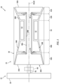
FIG. 2 is a partial illustration of a stationary structure at a mechanical joint. -
FIG. 3 is a partial side sectional illustration of the stationary structure at line 3-3 inFIG. 2 . -
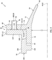
FIG. 4 is a partial side sectional illustration of the stationary structure at line 4-4 inFIG. 2 . -
FIG. 5 is a partial illustration of the first engine component. -
FIG. 6 is an enlarged illustration of a portion of the first engine component. -
FIG. 7 is an illustration of the second engine component. -
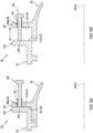
FIGS. 8A and 8B illustrate a sequence for disassembling the engine components. -
FIG. 9 is a partial illustration of the first engine component with another arrangement of apertures in its mount. -
FIG. 1 schematically illustrates agas turbine engine 20 for an aircraft. Thisgas turbine engine 20 may be included within a propulsion system for the aircraft. Thegas turbine engine 20, for example, may be configured as a turbofan gas turbine engine, a turbojet gas turbine engine, a turboprop gas turbine engine or a turboshaft gas turbine engine. Thegas turbine engine 20 may alternatively be included within an electrical power generation system for the aircraft. Thegas turbine engine 20, for example, may be configured as an auxiliary power unit (APU). Thegas turbine engine 20 of the present disclosure, however, is not limited to the foregoing exemplary gas turbine engine types. Furthermore, thegas turbine engine 20 may also be configured for non-aircraft applications. Thegas turbine engine 20, for example, may be configured as a (e.g., ground-based) industrial gas turbine engine for an electrical power generation system. Thegas turbine engine 20 of the present disclosure may be configured with a single spool, with two spools (e.g., seeFIG. 1 ), or with more than two spools depending on, for example, power requirements. - The
gas turbine engine 20 ofFIG. 1 includes amechanical load 22 and a gasturbine engine core 24 configured to drive rotation of themechanical load 22. Themechanical load 22 may be configured as or otherwise include arotor 26 of thegas turbine engine 20. Themechanical load 22, for example, may be configured as a bladed propulsor rotor for the aircraft propulsion system. Examples of the propulsor rotor include, but are not limited to: a fan rotor for the turbofan gas turbine engine; a compressor rotor for the turbojet gas turbine engine; a propeller rotor for the turboprop gas turbine engine; and a helicopter rotor (e.g., a main rotor) for the turboshaft gas turbine engine. Themechanical load 22 may alternatively be configured as a generator rotor for the power generation system. - The
engine core 24 ofFIG. 1 includes one or morerotating structures stationary structure 30. Thisengine core 24 also includes a plurality ofbearings 32 rotatably mounting therotating structures stationary structure 30. - The first (e.g., low speed)
rotating structure 28A includes a first (e.g., low pressure (LP))compressor rotor 34A, a first (e.g., low pressure)turbine rotor 36A and a first (e.g., low speed)shaft 38A. Thefirst compressor rotor 34A is arranged within and part of a first (e.g., low pressure)compressor section 40A of theengine core 24. Thefirst turbine rotor 36A is arranged within and part of a first (e.g., low pressure)turbine section 42A of theengine core 24. Thefirst shaft 38A extends axially along a rotational axis 44 between and is connected to thefirst compressor rotor 34A and thefirst turbine rotor 36A, where the firstrotating structure 28A is rotatable about the rotational axis 44. - The first
rotating structure 28A may also be rotatably coupled to themechanical load 22 and itsrotor 26. Themechanical load rotor 26, for example, may be coupled to the firstrotating structure 28A through a direct drive coupling. This direct drive coupling may be configured as or otherwise include anoutput shaft 46. With such a direct drive coupling, themechanical load rotor 26 and the firstrotating structure 28A may rotate at a common (e.g., the same) rotational speed. Alternatively, themechanical load rotor 26 may be coupled to the firstrotating structure 28A through a geartrain 48 (see dashed line); e.g., a transmission. Thisgeartrain 48 may be configured as an epicyclic geartrain. With such a geared coupling, themechanical load rotor 26 may rotate at a different (e.g., slower) rotational speed than the firstrotating structure 28A. - The second (e.g., high speed)
rotating structure 28B includes a second (e.g., high pressure (HP))compressor rotor 34B, a second (e.g., high pressure)turbine rotor 36B and a second (e.g., high speed)shaft 38B. Thesecond compressor rotor 34B is arranged within and part of a second (e.g., high pressure)compressor section 40B of theengine core 24. Thesecond turbine rotor 36B is arranged within and part of a second (e.g., high pressure)turbine section 42B of theengine core 24. Thesecond shaft 38B extends axially along the rotational axis 44 between and is connected to thesecond compressor rotor 34B and thesecond turbine rotor 36B, where the secondrotating structure 28B is rotatable about the rotational axis 44. The secondrotating structure 28B ofFIG. 1 and itssecond shaft 38B axially overlap and circumscribe thefirst shaft 38A; however, theengine core 24 of the present disclosure is not limited to such an exemplary arrangement. - The
stationary structure 30 is configured to at least partially or completely house thefirst compressor section 40A, thesecond compressor section 40B, acombustor section 50 of theengine core 24, thesecond turbine section 42B and thefirst turbine section 42A, where theengine sections gas turbine engine 20 and an exhaust from thegas turbine engine 20. Thestationary structure 30 ofFIG. 1 axially overlaps and extends circumferentially about (e.g., completely around) the firstrotating structure 28A and the secondrotating structure 28B. - During operation, air enters the
gas turbine engine 20 through the airflow inlet. This air is directed into at least a core flowpath which extends sequentially through theengine sections - The core air is compressed by the
first compressor rotor 34A and thesecond compressor rotor 34B and directed into acombustion chamber 52 of a combustor in thecombustor section 50. Fuel is injected into thecombustion chamber 52 and mixed with the compressed core air to provide a fuel-air mixture. This fuel-air mixture is ignited and combustion products thereof flow through and sequentially cause thesecond turbine rotor 36B and thefirst turbine rotor 36A to rotate. The rotation of thesecond turbine rotor 36B and thefirst turbine rotor 36A respectively drive rotation of thesecond compressor rotor 34B and thefirst compressor rotor 34A and, thus, compression of the air received from the airflow inlet. The rotation of thefirst turbine rotor 36A ofFIG. 1 also drives rotation of themechanical load 22 and itsrotor 26. Where themechanical load rotor 26 is configured as the propulsor rotor, therotor 26 propels additional air through or outside of thegas turbine engine 20 to provide, for example, a majority of aircraft propulsion system thrust. Where themechanical load rotor 26 is configured as the generator rotor, rotation of therotor 26 facilitates generation of electricity. -
FIGS. 2-4 illustrate a portion of thestationary structure 30. Thisstationary structure 30 includes a plurality ofengine components fastener assemblies 58 coupling theengine components - The
first engine component 54 may be configured as a tubular engine case for thegas turbine engine 20. Thefirst engine component 54 ofFIGS. 3 and4 , for example, extends axially along acenterline axis 62 of thestationary structure 30 to an (e.g., forward or aft)axial end 64 of thefirst engine component 54, whichcenterline axis 62 may be parallel and/or coaxial with the rotational axis 44. Thisfirst engine component 54 includes afirst component base 66 and afirst component mount 68; e.g., a flange and/or a rim. - The
first component base 66 extends axially along thecenterline axis 62 to the first componentaxial end 64. Thefirst component base 66 extends circumferentially about (e.g., completely around) the centerline axis 62 (see alsoFIG. 5 ), which may thereby provide thefirst component base 66 with a tubular geometry. Thefirst component base 66 extends radially between and to aninner side 70 of thefirst component base 66 and anouter side 72 of thefirst component base 66. - The
first component mount 68 is connected to (e.g., formed integral with or otherwise bonded to) thefirst component base 66. Thefirst component mount 68 is disposed at (e.g., on, adjacent or proximate) the first componentaxial end 64. Thefirst component mount 68 ofFIGS. 3 and4 , for example, extends axially along thecenterline axis 62 between and to an axialfirst side 74 of thefirst component mount 68 and an axial second side 76 of thefirst component mount 68, where the first mount second side 76 is slightly recessed axially inward from the first componentaxial end 64. Of course, the first mount second side 76 may alternatively be axially aligned with the first componentaxial end 64 in other embodiments. Thefirst component mount 68 extends circumferentially about (e.g., completely around) thecenterline axis 62 and the first component base 66 (see alsoFIG. 5 ), which may thereby provide thefirst component mount 68 with an annular geometry. Thefirst component mount 68 projects radially outward from thefirst component base 66 at the first baseouter side 72 to a radial outerdistal end 78 of thefirst component mount 68. - Referring to
FIG. 5 , thefirst component mount 68 is configured with a plurality offirst component apertures first component apertures 80 are arranged circumferentially about thecenterline axis 62 in an annular array; e.g., a circular array. Thefirst component apertures 80 may also be equally spaced circumferentially about thecenterline axis 62. Each circumferentially neighboring pair of thefirst component apertures 80 ofFIG. 6 , for example, is spaced by a common (e.g., the same) circumferential distance 82. This circumferential distance 82 may be measured between centers of the respective circumferentially neighboringfirst component apertures 80. Outer peripheries of each of the circumferentially neighboring pairs of thefirst component apertures 80 may also (or alternatively) be separated by acommon circumferential distance 84 where, for example, thefirst component apertures 80 have acommon size 86; e.g., diameter. - The
first component apertures 80A ofFIG. 5 include NT-number offirst fastener apertures 86A-C (generally referred to as "86") arranged into NFG-number offastener aperture groups 88A-C (generally referred to as "88"), where the NT-number offirst fastener apertures 86 is an odd number offirst fastener apertures 86. Thefirst component apertures 80B also include NIA-number of intergroup apertures 90A-C (generally referred to as "90") (e.g., spacer apertures and/or jacking apertures) interspersed / interposed with the fastener aperture groups 88, where the NIA-number ofintergroup apertures 90 is equal to the NFG-number of fastener aperture groups 88. - Referring to
FIGS. 3 and4 , each of thefirst component apertures centerline axis 62 through thefirst engine component 54 and itsfirst component mount 68. Eachfirst fastener aperture 86 ofFIG. 3 , for example, is formed as an un-threaded through-hole in abase 92 of thefirst component mount 68. Eachfirst fastener aperture 86 extends axially through themount base 92 between and to the first mountfirst side 74 and the first mount second side 76. Eachintergroup aperture 90 ofFIG. 4 may be formed as a threaded bore in a respective insert 94 (e.g., a threaded insert, a jacking insert, etc.) mounted to themount base 92. Eachintergroup aperture 90 extends through the respective insert 94 (and thereby through the mount base 92) between and to the first mount second side 76 and an axialdistal end 96 of theinsert 94, where theinsert 94 may project axially out from the first mountfirst side 74 to itsdistal end 96. - Referring to
FIG. 5 , the groups 88 of thefirst fastener apertures 86 include afirst group 88A, asecond group 88B and athird group 88C. Thefirst group 88A of thefirst fastener apertures 86A is formed by N1-number of thefirst fastener apertures 86A. Thesecond group 88B of thefirst fastener apertures 86B is formed by N2-number of thefirst fastener apertures 86B. Thethird group 88C of thefirst fastener apertures 86C is formed by N3-number of thefirst fastener apertures 86C. The N1-number of thefirst fastener apertures 86A may be the same as (e.g., equal to) the N3-number of thefirst fastener apertures 86C. The N2-number of thefirst fastener apertures 86B may be different (e.g., less) than the N1-number of thefirst fastener apertures 86A and/or the N3-number of thefirst fastener apertures 86C. The N1-number and the N3-number of thefirst fastener apertures first fastener apertures first fastener apertures 86B may be an odd number of thefirst fastener apertures 86B. Each of these fastener aperture groups 88 ofFIG. 5 may be configured without any other apertures. - With the foregoing arrangement of the fastener aperture groups 88, the
intergroup apertures 90 are asymmetrically spaced circumferentially about thecenterline axis 62 and provide an integral alignment feature as described below in further detail. In particular, eachintergroup aperture 90 is disposed between a circumferentially neighboring pair of the fastener aperture groups 88. More particularly, eachintergroup aperture 90 is disposed between and circumferentially adjacent (A) one of thefirst fastener apertures 86 in a first of the circumferentially neighboring pair of the fastener aperture groups 88 and (B) one of thefirst fastener apertures 86 in a second of the circumferentially neighboring pair of the fastener aperture groups 88. Each circumferentially neighboring pair of the fastener aperture groups 88 ofFIG. 5 may thereby be separated by (e.g., only) a single respective one of theintergroup apertures 90. Thefirst intergroup aperture 90A is X1-number of degrees from thesecond intergroup aperture 90B. Thefirst intergroup aperture 90A is X2-number of degrees from thethird intergroup aperture 90C. Thesecond intergroup aperture 90B is X3-number of degrees from thethird intergroup aperture 90C. The X1-number of degrees may be the same as (e.g., equal to) the X2-number of degrees. The X3-number of degrees may be different (e.g., less) than the X1-number of degrees and/or the X2-number of degrees. However, the X3-number of degrees may be within plus/minus two, five or ten degrees of the X1-number of degrees and/or the X2-number of degrees, or vice versa. It should be noted, the closer the X3-number of degrees is to the X1-number of degrees and/or the X2-number of degrees, the more evenly loads and/or stresses will be distributed about thefirst component mount 68 and thej oint 60 ofFIGS. 2-4 . - Referring to
FIGS. 3 and4 , thesecond engine component 56 may be configured as a tubular engine case for thegas turbine engine 20. Thesecond engine component 56 ofFIGS. 3 and4 , for example, extends axially along thecenterline axis 62 to an (e.g., aft or forward)axial end 98 of thesecond engine component 56. Thissecond engine component 56 includes asecond component base 100 and asecond component mount 102; e.g., a flange and/or a rim. - The
second component base 100 extends axially along thecenterline axis 62 to the second componentaxial end 98. Thesecond component base 100 extends circumferentially about (e.g., completely around) the centerline axis 62 (see alsoFIG. 7 ), which may thereby provide thesecond component base 100 with a tubular geometry. Thesecond component base 100 extends radially between and to aninner side 104 of thesecond component base 100 and anouter side 106 of thesecond component base 100. - The
second component mount 102 is connected to (e.g., formed integral with or otherwise bonded to) thesecond component base 100. Thesecond component mount 102 is disposed at (e.g., on, adjacent or proximate) the second componentaxial end 98. Thesecond component mount 102 ofFIGS. 3 and4 , for example, extends axially along thecenterline axis 62 between and to an axialfirst side 108 of thesecond component mount 102 and an axial second side 110 of thesecond component mount 102, where the second mount second side 110 is axially aligned with the second componentaxial end 98. Of course, the second mount second side 110 may alternatively be slightly recessed axially inward from the second componentaxial end 98 in other embodiments. Thesecond component mount 102 extends circumferentially about (e.g., completely around) thecenterline axis 62 and the first component base 66 (see alsoFIG. 9 ), which may thereby provide thesecond component mount 102 with an annular geometry. Thesecond component mount 102 projects radially outward from thesecond component base 100 at the second baseouter side 106 to a radial outerdistal end 112 of thesecond component mount 102. - Referring to
FIG. 7 , thesecond component mount 102 is configured with a plurality of second component apertures 114. These second component apertures 114 are arranged circumferentially about thecenterline axis 62 in an annular array; e.g., a circular array. Each of these second component apertures 114 may be configured as a second fastener aperture 116A, 116B or 116C (generally referred to as "116"). These second fastener apertures 116 are distributed circumferentially about thecenterline axis 62 in a common pattern as thefirst fastener apertures 86 ofFIG. 5 ; e.g., the second fastener apertures 116 and thefirst fastener apertures 86 have matching / complimentary patterns. The second fastener apertures 116 ofFIG. 7 , for example, are arranged into a plurality ofgroups 118A-C (generally referred to as "118"). Thefirst group 118A of the second fastener apertures 116A may match (e.g., have the same number as and complimentary aperture positions to) thefirst group 88A of thefirst fastener apertures 86A ofFIG. 5 . Thesecond group 118B of the second fastener apertures 116B may match thesecond group 88B of thefirst fastener apertures 86B ofFIG. 5 . Thethird group 118C of the second fastener apertures 116C may match thethird group 88C of thefirst fastener apertures 86C ofFIG. 5 . - Whereas the
first component apertures 80 ofFIG. 5 include theintergroup apertures 90, the groups 118 of the second fastener apertures 116 ofFIG. 7 are separated by non-perorated portions of thesecond component mount 102. Arespective portion 120A-C (generally referred to as "120") of a surface 122 of thesecond component mount 102 at its second side 110, for example, is disposed between each circumferentially neighboring pair of the fastener aperture groups 118. More particularly, eachportion 120 of the second mount surface 122 extends uninterrupted (e.g., without any apertures, protrusions and/or other interruptions) circumferentially between and to (A) one of the second fastener apertures 116 in a first of the circumferentially neighboring pair of the fastener aperture groups 118 and (B) one of the second fastener apertures 116 in a second of the circumferentially neighboring pair of the fastener aperture groups 118. These secondmount surface portions 120 are distributed circumferentially about thecenterline axis 62 in a common pattern as theintergroup apertures 90 ofFIG. 5 . - Referring to
FIG. 3 , each of the second fastener apertures 116 extends axially along thecenterline axis 62 through thesecond engine component 56 and itssecond component mount 102. Each second fastener aperture 116 ofFIG. 3 , for example, is formed as an un-threaded through-hole in abase 124 of thesecond component mount 102. Each second fastener aperture 116 extends axially through themount base 124 between and to the second mountfirst side 108 and the second mount second side 110. - Referring to
FIGS. 3 and4 , thefirst engine component 54 and thesecond engine component 56 are arranged together at the mechanical joint 60. Thesecond engine component 56, for example, may be translated (e.g., slid) axially over an end portion (e.g., an alignment portion) of thefirst component base 66 until thesecond component mount 102 axially engages thefirst component mount 68. The second mount surface 122, for example, may axially abut against and contact an axially opposing surface 126 of thefirst component mount 68 at its second side 76. At least one of theengine components centerline axis 62 such that (A) each of thefirst fastener apertures 86 is aligned (e.g., coaxial) with a corresponding one of the second fastener apertures 116 (seeFIG. 3 ) and (B) each of theintergroup apertures 90 is aligned with a corresponding one of the second mount surface portions 120 (seeFIG. 4 ). More particularly, thefirst group 88A of thefirst fastener apertures 86A ofFIG. 5 are respectively aligned with thefirst group 118A of the second fastener apertures 116A ofFIG. 7 . Thesecond group 88B of thefirst fastener apertures 86B ofFIG. 5 are respectively aligned with thesecond group 118B of the second fastener apertures 116B ofFIG. 7 . Thethird group 88C of thefirst fastener apertures 86C ofFIG. 5 are respectively aligned with thethird group 118C of the second fastener apertures 116C ofFIG. 7 . Similarly, thefirst intergroup aperture 90A ofFIG. 5 is aligned with thefirst portion 120A of the second mount surface 122 ofFIG. 7 . Thesecond intergroup aperture 90B ofFIG. 5 is aligned with thesecond portion 120B of the second mount surface 122 ofFIG. 7 . Thethird intergroup aperture 90C ofFIG. 5 is aligned with thethird portion 120C of the second mount surface 122 ofFIG. 7 . Referring toFIG. 4 , eachintergroup aperture 90 may thereby extend axially through thefirst component mount 68 to the second mount surface 122; e.g., the second mount surface 122 covers (e.g., radially and circumferentially overlaps) eachintergroup aperture 90. By clocking theengine components engine components - Referring to
FIGS. 2 and3 , thefastener assemblies 58 are mated with thefastener apertures 86 and 116 to secure theengine components fastener assembly 58 ofFIG. 3 , for example, includes a fastener 128 (e.g., a bolt) and anut 130. Thefastener 128 ofFIG. 3 includes ahead 132 and ashank 134 connected to thehead 132. Thehead 132 may be abutted against the first component mount 68 (or alternatively the second component mount 102). Theshank 134 may project out from thehead 132, sequentially through a respectivefirst fastener aperture 86 and an aligned second fastener aperture 116 to a distal end portion. Thenut 130 is mounted (e.g., threaded) onto the distal end portion and tightened to clamp the component mounts 68 and 102 together between thehead 132 and thenut 130. With such an arrangement, each of thefastener apertures 86 and 116 receives (e.g., is plugged by) a respective one of thefasteners 128. However, each of theintergroup apertures 90 ofFIGS. 2 and4 is open; e.g., empty. The intergroup apertures 90 may remain open during operation of thegas turbine engine 20 ofFIG. 1 . - While the
intergroup apertures 90 may remain open during gas turbine engine operation, each of theintergroup apertures 90 ofFIG. 8A and 8B may be mated with (e.g., receive) a respective tool during disassembly of thestationary structure 30; e.g., when thefirst engine component 54 is detached from thesecond engine component 56, or vice versa. Each tool may be configured as a jacking device. Each tool ofFIG. 8A , for example, is configured as abolt 136 which is threaded into therespective intergroup aperture 90. Eachbolt 136 may be threaded until anend 138 of thebolt 136 engages (e.g., axially contacts) the second mount surface 122. After removal of thefastener assembly 58, eachbolt 136 ofFIG. 8B may continue to be threaded to press thesecond component mount 102 and its second mount surface 122 axially away from thefirst component mount 68 until, for example, thesecond engine component 56 is disengaged from thefirst engine component 54. - While the N1-number and the N3-number may be even numbers and the N2-number may be an odd number as described above with respect to
FIG. 5 , the present disclosure is not limited to such an arrangement. For example, the N1-number and the N3-number may be odd numbers and the N2-number may be an even number. In another example, referring toFIG. 9 , the N1-number, the N2-number and the N3-number may all be odd (or even) numbers as long as the N2-number remains different than the N1-number and the N3-number. - While the
first fastener apertures 86 ofFIG. 5 are arranged into three groups 88, the present disclosure is not limited to such an arrangement. For example, thefirst fastener apertures 86 may be arranged into two fastener aperture groups 88 or four or more fastener aperture groups 88. - While the
engine components engine components stationary structure 30 such as, but not limited to, an internal support structure. Examples of the internal support structure include, but are not limited to, a bearing support structure, a frame, a mid-turbine case, a vane array, etc. - While various embodiments of the present disclosure have been described, it will be apparent to those of ordinary skill in the art that many more embodiments and implementations are possible within the scope of the disclosure. For example, the present disclosure as described herein includes several aspects and embodiments that include particular features. Although these features may be described individually, it is within the scope of the present disclosure that some or all of these features may be combined with any one of the aspects and remain within the scope of the disclosure. Accordingly, the present disclosure is not to be restricted except in light of the attached claims and their equivalents.
Claims (15)
- A structure (30) for a gas turbine engine (20), comprising:a first engine component (54) comprising a plurality of component apertures (80) equally spaced circumferentially about an axis (62), the plurality of component apertures (80) including a plurality of first fastener apertures (86) and a plurality of intergroup apertures (90), the plurality of first fastener apertures (86) arranged into a plurality of groups (88) including a first group and a second group, the first group formed by N1-number of the plurality of first fastener apertures (86), the second group formed by N2-number of the plurality of first fastener apertures (86) where the N2-number is different than the N1-number, and each of the plurality of intergroup apertures (90) disposed circumferentially between and adjacent a respective circumferentially neighboring pair of the plurality of groups (88);a second engine component (56) comprising a surface (122) and a plurality of second fastener apertures (116), the surface (122) axially engaging the first engine component (54) and covering the plurality of intergroup apertures (90); anda plurality of fasteners (128) attaching the first engine component (54) and the second engine component (56) together, each of the plurality of fasteners (128) mated with a respective one of the plurality of first fastener apertures (86) and a respective one of the plurality of second fastener apertures (116).
- The structure (30) of claim 1, wherein the first engine component (54) is configured as an engine case.
- The structure (30) of claim 1 or 2, wherein:the first engine component (54) further comprises a mount (68);the mount (68) extends circumferentially about the axis (62); andeach of the plurality of component apertures (80) extends axially through the mount (68).
- The structure (30) of claim 1, 2 or 3, wherein a first of the plurality of intergroup apertures (90) comprises a threaded aperture.
- The structure (30) of any preceding claim, wherein a first of the plurality of intergroup apertures (90) is configured to be empty during operation of the gas turbine engine (20).
- The structure (30) of any preceding claim, wherein a first of the plurality of intergroup apertures (90) is configured to mate with a tool (136) during disassembly of the structure (30) where the tool (136) threads into the first of the plurality of intergroup apertures (90) and presses axially against the surface (122).
- The structure (30) of any preceding claim, wherein:the N1-number is an even number; and/orthe N2-number is an odd number.
- The structure (30) of any preceding claim, wherein the first engine component (54) is configured with a NT-number of the plurality of first fastener apertures (86), and the NT-number is an odd number.
- The structure (30) of any preceding claim, wherein:the plurality of groups (88) further includes a third group;the third group is formed by N3-number of the plurality of first fastener apertures (86); andthe N3-number is an even number and/or is different than the N2-number,wherein, optionally, the N3-number is equal to the N1-number.
- The structure (30) of claim 9, wherein the plurality of intergroup apertures (90) include:a first intergroup aperture disposed circumferentially between and adjacent the first group and the second group;a second intergroup aperture disposed circumferentially between and adjacent the first group and the third group; anda third intergroup aperture disposed circumferentially between and adjacent the second group and the third group.
- The structure (30) of any preceding claim, wherein:the plurality of intergroup apertures (90) include a first intergroup aperture, a second intergroup aperture and a third intergroup aperture;the first intergroup aperture is X1-number of degrees from the second intergroup aperture about the axis (62); andthe first intergroup aperture is X2-number of degrees from the third intergroup aperture about the axis (62) where the X2-number is equal to the Xi-number, and, optionally, the second intergroup aperture is X3-number of degrees from the third intergroup aperture about the axis (62) where the X3-number is within plus or minus five degrees of the X1-number.
- A structure (30) for a gas turbine engine (20), comprising:a first engine component (54) comprising a first component mount (68) and a plurality of component apertures (80) arranged circumferentially about an axis (62), the first component mount (68) extending circumferentially about the axis (62), each of the plurality of component apertures (80) extending axially through the first component mount (68), the plurality of component apertures (80) including a plurality of first fastener apertures (86) and a spacer aperture (90) where a first of the plurality of first fastener apertures (86) is circumferentially between and adjacent a second of the plurality of first fastener apertures (86) and the spacer aperture (90), and a circumferential spacing between the first of the plurality of first fastener apertures (86) and the second of the plurality of first fastener apertures (86) equal to a circumferential spacing between the first of the plurality of first fastener apertures (86) and the spacer aperture (90);a second engine component (56) comprising a surface (122) and a plurality of second fastener apertures (116), the surface (122) circumferentially and radially overlapping the spacer aperture (90); anda plurality of fasteners (128) attaching the first engine component (54) and the second engine component (56) together, each of the plurality of fasteners (128) mated with a respective one of the plurality of first fastener apertures (86) and a respective one of the plurality of second fastener apertures (116).
- The structure (30) of claim 12, wherein:the spacer aperture (90) is circumferentially between and adjacent the first of the plurality of first fastener apertures (86) and a third of the plurality of first fastener apertures (86); andthe circumferential spacing between the first of the plurality of first fastener apertures (86) and the spacer aperture (90) is equal to a circumferential spacing between the spacer aperture (90) and the third of the plurality of first fastener apertures (86), and, optionally, the third of the plurality of first fastener apertures (86) is circumferentially between and adjacent the spacer aperture (90) and a fourth of the plurality of first fastener apertures (86), and the circumferential spacing between the third of the plurality of first fastener apertures (86) and the spacer aperture (90) is equal to a circumferential spacing between the third of the plurality of first fastener apertures (86) and the fourth of the plurality of first fastener apertures (86).
- The structure (30) of claim 12 or 13, wherein:the plurality of component apertures (80) further includes a plurality of intergroup apertures (90);the plurality of first fastener apertures (86) are arranged into a plurality of groups (88) including a first group and a second group;the first group is formed by N1-number of the plurality of first fastener apertures (86) including the first of the plurality of first fastener apertures (86) and the second of the plurality of first fastener apertures (86);the second group is formed by N2-number of the plurality of first fastener apertures (86) where the N2-number is different than the N1-number; andeach of the plurality of intergroup apertures (90) is disposed circumferentially between and adjacent a respective circumferentially neighboring pair of the plurality of groups (88), and the plurality of intergroup apertures (90) includes the spacer aperture (90).
- A structure (30) for a gas turbine engine (20), comprising:a first engine component (54) comprising a plurality of component apertures (80) equally spaced circumferentially about an axis (62), the plurality of component apertures (80) including a plurality of first fastener apertures (86) and a plurality of intergroup apertures (90), the plurality of first fastener apertures (86) arranged into a plurality of groups (88) including a first group and a second group, the first group formed by N1-number of the plurality of first fastener apertures (86), the second group formed by N2-number of the plurality of first fastener apertures (86) where the N2-number is different than the N1-number, each of the plurality of intergroup apertures (90) disposed circumferentially between and adjacent a respective circumferentially neighboring pair of the plurality of groups (88), and each of the plurality of intergroup apertures (90) configured to be empty during operation of the gas turbine engine (20);a second engine component (56) comprising a plurality of second fastener apertures (116); anda plurality of fasteners (128) attaching the first engine component (54) and the second engine component (56) together, each of the plurality of fasteners (128) mated with a respective one of the plurality of first fastener apertures (86) and a respective one of the plurality of second fastener apertures (116).
Applications Claiming Priority (1)
| Application Number | Priority Date | Filing Date | Title |
|---|---|---|---|
| US17/746,541 US11821330B1 (en) | 2022-05-17 | 2022-05-17 | Aperture pattern for gas turbine engine component with integral alignment feature |
Publications (2)
| Publication Number | Publication Date |
|---|---|
| EP4279712A2 true EP4279712A2 (en) | 2023-11-22 |
| EP4279712A3 EP4279712A3 (en) | 2024-04-03 |
Family
ID=86386859
Family Applications (1)
| Application Number | Title | Priority Date | Filing Date |
|---|---|---|---|
| EP23174033.3A Pending EP4279712A3 (en) | 2022-05-17 | 2023-05-17 | Aperture pattern for gas turbine engine component with integral alignment feature |
Country Status (3)
| Country | Link |
|---|---|
| US (1) | US11821330B1 (en) |
| EP (1) | EP4279712A3 (en) |
| CA (1) | CA3201368A1 (en) |
Families Citing this family (1)
| Publication number | Priority date | Publication date | Assignee | Title |
|---|---|---|---|---|
| US20250297556A1 (en) * | 2024-03-19 | 2025-09-25 | Pratt & Whitney Canada Corp. | Aircraft powerplant with joint shield |
Family Cites Families (6)
| Publication number | Priority date | Publication date | Assignee | Title |
|---|---|---|---|---|
| US8721278B2 (en) * | 2010-08-02 | 2014-05-13 | Siemens Energy, Inc. | Exhaust manifold flange connection |
| GB201110436D0 (en) * | 2011-06-21 | 2011-08-03 | Rolls Royce Plc | Joint assembly |
| FR2986582B1 (en) * | 2012-02-06 | 2014-03-14 | Snecma | BLOWER HOUSING FOR A GAS TURBINE ENGINE HAVING A FLANGE FOR ATTACHING EQUIPMENT |
| US10190439B2 (en) | 2014-04-23 | 2019-01-29 | Pratt & Whitney Canada Corp. | Frangible mounting arrangement and method for providing same |
| US10247038B2 (en) * | 2016-10-20 | 2019-04-02 | Rolls-Royce Corporation | Flange fastening assembly in a gas turbine engine |
| US10961869B2 (en) * | 2019-03-19 | 2021-03-30 | Raytheon Technologies Corporation | Concentric jack screw holes |
-
2022
- 2022-05-17 US US17/746,541 patent/US11821330B1/en active Active
-
2023
- 2023-05-17 EP EP23174033.3A patent/EP4279712A3/en active Pending
- 2023-05-17 CA CA3201368A patent/CA3201368A1/en active Pending
Also Published As
| Publication number | Publication date |
|---|---|
| US11821330B1 (en) | 2023-11-21 |
| US20230374914A1 (en) | 2023-11-23 |
| CA3201368A1 (en) | 2023-11-17 |
| EP4279712A3 (en) | 2024-04-03 |
Similar Documents
| Publication | Publication Date | Title |
|---|---|---|
| EP3321488B1 (en) | Gas turbine engine accessories arrangement | |
| US5285700A (en) | Rotor balancing | |
| CA2524113A1 (en) | Gas turbine engine and method of assembling same | |
| EP4163475A1 (en) | Rotor assembly for a gas turbine engine and method for assembling same | |
| US20140060079A1 (en) | Aeroengine arrangement | |
| EP3971402A1 (en) | Fan drive gear system module and inlet guide vane coupling mechanism | |
| EP3273013B1 (en) | Assembly for a turbine engine | |
| EP1087101B1 (en) | Coupling assembly and method for connecting air ducts in gas turbine rotors | |
| US11821330B1 (en) | Aperture pattern for gas turbine engine component with integral alignment feature | |
| EP4065818B1 (en) | METHOD FOR ASSEMBLING AND DISASSEMBLING A GAS TURBINE DRIVE AND ARRANGEMENTS FOR THIS | |
| US10202858B2 (en) | Reconfiguring a stator vane structure of a turbine engine | |
| US10746041B2 (en) | Shroud and shroud assembly process for variable vane assemblies | |
| US12215630B2 (en) | Flex coupler for hybrid gas turbine engine powerplant | |
| US12540550B2 (en) | Tie shaft for engine rotating assembly | |
| US20260098485A1 (en) | Powerplant jacking insert with exterior and interior threads | |
| US12515807B2 (en) | Bolted connection between mounting bracket and aircraft engine case(s) | |
| US11788413B2 (en) | Gas turbine engine shaft with lobed support structure | |
| WO2011153150A1 (en) | Compressor case lining | |
| EP4368344A1 (en) | Centering a washer to a fastener element during installation | |
| US11187099B1 (en) | Turbine shroud with containment features | |
| CA3288361A1 (en) | Powerplant jacking insert with exterior and interior threads | |
| CA3262409A1 (en) | Bolted connection between mounting bracket and aircraft engine case(s) |
Legal Events
| Date | Code | Title | Description |
|---|---|---|---|
| PUAI | Public reference made under article 153(3) epc to a published international application that has entered the european phase |
Free format text: ORIGINAL CODE: 0009012 |
|
| STAA | Information on the status of an ep patent application or granted ep patent |
Free format text: STATUS: THE APPLICATION HAS BEEN PUBLISHED |
|
| AK | Designated contracting states |
Kind code of ref document: A2 Designated state(s): AL AT BE BG CH CY CZ DE DK EE ES FI FR GB GR HR HU IE IS IT LI LT LU LV MC ME MK MT NL NO PL PT RO RS SE SI SK SM TR |
|
| PUAL | Search report despatched |
Free format text: ORIGINAL CODE: 0009013 |
|
| AK | Designated contracting states |
Kind code of ref document: A3 Designated state(s): AL AT BE BG CH CY CZ DE DK EE ES FI FR GB GR HR HU IE IS IT LI LT LU LV MC ME MK MT NL NO PL PT RO RS SE SI SK SM TR |
|
| RIC1 | Information provided on ipc code assigned before grant |
Ipc: F01D 25/24 20060101AFI20240227BHEP |
|
| STAA | Information on the status of an ep patent application or granted ep patent |
Free format text: STATUS: REQUEST FOR EXAMINATION WAS MADE |
|
| 17P | Request for examination filed |
Effective date: 20241003 |
|
| RBV | Designated contracting states (corrected) |
Designated state(s): AL AT BE BG CH CY CZ DE DK EE ES FI FR GB GR HR HU IE IS IT LI LT LU LV MC ME MK MT NL NO PL PT RO RS SE SI SK SM TR |
|
| GRAP | Despatch of communication of intention to grant a patent |
Free format text: ORIGINAL CODE: EPIDOSNIGR1 |
|
| STAA | Information on the status of an ep patent application or granted ep patent |
Free format text: STATUS: GRANT OF PATENT IS INTENDED |
|
| INTG | Intention to grant announced |
Effective date: 20260116 |