EP4279657A1 - A paving screed, a paving screed extension, a paving screed broadening part and a paver - Google Patents
A paving screed, a paving screed extension, a paving screed broadening part and a paver Download PDFInfo
- Publication number
- EP4279657A1 EP4279657A1 EP22173776.0A EP22173776A EP4279657A1 EP 4279657 A1 EP4279657 A1 EP 4279657A1 EP 22173776 A EP22173776 A EP 22173776A EP 4279657 A1 EP4279657 A1 EP 4279657A1
- Authority
- EP
- European Patent Office
- Prior art keywords
- screed
- body partition
- cross strut
- paving
- screed body
- Prior art date
- Legal status (The legal status is an assumption and is not a legal conclusion. Google has not performed a legal analysis and makes no representation as to the accuracy of the status listed.)
- Pending
Links
Images


Classifications
-
- E—FIXED CONSTRUCTIONS
- E01—CONSTRUCTION OF ROADS, RAILWAYS, OR BRIDGES
- E01C—CONSTRUCTION OF, OR SURFACES FOR, ROADS, SPORTS GROUNDS, OR THE LIKE; MACHINES OR AUXILIARY TOOLS FOR CONSTRUCTION OR REPAIR
- E01C19/00—Machines, tools or auxiliary devices for preparing or distributing paving materials, for working the placed materials, or for forming, consolidating, or finishing the paving
- E01C19/48—Machines, tools or auxiliary devices for preparing or distributing paving materials, for working the placed materials, or for forming, consolidating, or finishing the paving for laying-down the materials and consolidating them, or finishing the surface, e.g. slip forms therefor, forming kerbs or gutters in a continuous operation in situ
-
- E—FIXED CONSTRUCTIONS
- E01—CONSTRUCTION OF ROADS, RAILWAYS, OR BRIDGES
- E01C—CONSTRUCTION OF, OR SURFACES FOR, ROADS, SPORTS GROUNDS, OR THE LIKE; MACHINES OR AUXILIARY TOOLS FOR CONSTRUCTION OR REPAIR
- E01C2301/00—Machine characteristics, parts or accessories not otherwise provided for
- E01C2301/14—Extendable screeds
Definitions
- the invention relates to a paving screed, a paving screed extension, a paving screed broadening part and a paver.
- the invention is applicable on construction vehicles having a paving screed.
- the invention is applicable on pavers.
- the material (commonly asphalt) lies in front of the screed.
- the paver pulls the screed and the material is distributed, compacted and smoothed by the screed while the screed moves.
- the force of the material then causes the screed to deform. This is especially the case when bigger screed lengths are used.
- the force of the material onto the screed leads to an elastic deformation and the screed twists over the length because the material is normally only in touch with the lower end of the screed front surface.
- a screed tensioning device a hydraulic cylinder which delivers constant force, is used to suppress such effects.
- the constant force of the hydraulic cylinder is used to pull the lower end of the screed so the deformation -caused by the material- can be removed.
- screed tensioning is needed for screed lengths above 7 m.
- the location where the screed tensioning device is connected to can be changed. With this, the effect of the tensioning device can be adjusted for the paving lengths the tensioning device is needed for.
- This solution requires active parts like the hydraulic cylinder, which have to be maintained and controlled to function properly.
- Such solutions using cylinders are for example described in CN102864726 .
- An object of the invention is to provide a paving screed or paving screed extension with an improved resistance to deformation preferably resulting in an evenly distribution of the paving material over the whole length of the paving screed.
- the object is achieved by a paving screed according to claim 1.
- the paving screed has at least one screed body partition.
- the at least one screed body partition has at least one cross strut extending at a front side or at a back side of the screed body partition from a centered part to an outer part of the screed body partition.
- an outer end of the at least one cross strut arranged at the outer part of the screed body partition is positioned closer to a bottom side of the paving screed facing a pavement than an inner end of the at least one cross strut arranged at the centered part of the screed body partition.
- the cross strut transforms a bending of the screed body partition in horizontal direction into a twisting.
- the invention is based on the recognition that with the aid of the cross strut in the screed body partition a bending in horizontal direction of the screed caused by the force of the paving material can be used to induce twisting in the screed body and this twisting serves as a compensatory movement resulting in an even pavement facing surface of the paving screed and thus in evenly distributed material. Thus deformation in horizontal direction is transformed into a useful compensatory twisting movement.
- the invention further includes the recognition that this effect is achieved only by the arrangement of the cross strut obliquely from above at a centered part to bottom at an outer part. Thus by inducing the twisting the cross strut lifts the outer end of the screed body partition to level the height of the pavement facing surface of the paving screed.
- the inner end of the at least one cross strut is arranged at a position higher than a torsional centre of the screed body partition and the outer end of the at least one cross strut is arranged at a position lower than the torsional centre of the screed body partition.
- the at least cross strut further extends from a plane nearer to the front side to a plane nearer to a back side of the screed body partition.
- Such an arrangement may in particular be useful for application with restricted installation space.
- the at least one cross strut extends in a plane parallel to a front side of the screed body partition. This arrangement results in higher twisting and is thus normally preferred.
- the screed body partition is a main single screed section or one section of a main multiple sections screed or a screed extension, which is arranged behind and adjacent to a main screed section or a screed broadening part, which is arranged flanking to a main screed section.
- the arrangement of at least one cross strut in all of this sections or part of a paving screed may be useful.
- combinations of several cross struts in the different sections and or parts lead to a further improved complementary movement.
- each of the multiple sections has at least one cross strut.
- a first cross strut extends at a front side and a second cross strut extends at a back side of the screed body partition.
- the at least one cross strut is arranged at an angle in the range of 10 to 85° with respect to the bottom side of the paving screed.
- the at least one cross strut comprises several single struts.
- the at least one cross strut is massive or has a hollow structure, having for example a round, oval or polygonal cross-section.
- a tube can be used.
- the cross-section of the cross strut has to be designed sufficiently large to ensure buckling safety and on the other hand sufficiently small to allow twisting.
- cross strut is an integral part of a sheet element of the screed body partition, especially of a stabilizing angle sheet of the screed body partition.
- the cross strut can be integrated in further components of the screed body.
- the cross sheet has at least one recess.
- one of the two screed body partitions with at least one cross strut is arranged preferably in a left part of the paving screed while the other is arranged in a corresponding right part of the paving screed.
- the object is achieved by a paving screed extension according to claim 12.
- the paving screed extension is able to be arranged behind and adjacent to a main screed section and has at least one screed body partition.
- the at least one screed body partition has at least one cross strut extending at a front side or at a back side of the screed body partition from a centered part to an outer part of the screed body partition, wherein an outer end of the at least one cross strut arranged at the outer part of the screed body partition is positioned closer to a bottom side of the screed facing the pavement than an inner end of the at least one cross strut arranged at the centered part of the screed body partition, the cross strut transforming a bending of the screed body partition in horizontal direction into a twisting.
- a paving screed broadening part which is able to be arranged flanking to a main screed section and has at least one screed body partition.
- the at least one screed body partition has at least one cross strut extending at a front side or at a back side of the screed body partition from a centered part to an outer part of the screed body partition, wherein an outer end of the at least one cross strut arranged at the outer part of the screed body partition is positioned closer to a bottom side of the screed facing the pavement than an inner end of the at least one cross strut arranged at the centered part of the screed body partition, the cross strut transforming a bending of the screed body partition in horizontal direction into a twisting.
- the object is achieved by a paver according to claim 14.
- the paver has a paving screed according to the first aspect or a paving screed broadening part according to the second aspect or a paving screed extension according to the third aspect of the invention.
- Fig. 1 illustrates an embodiment of a paver 1 with a paving screed 2 according to the invention. Details of the paving screed construction especially regarding a cross strut will be discussed and shown with respect to Fig. 2 to Fig. 4B .
- the shown paver is a tracked paver 1 which accordingly comprises caterpillar tracks 9 for providing vehicle propulsion for the paver 1.
- the paver machine 1 comprises a hopper 3 in which road material is temporarily stored during paving. The road material is typically added to the hopper 3 from a truck.
- the road material may be asphalt.
- the paver 1 further comprises a paving screed 2 arranged at the rear of the paver 1.
- the paving screed 2 is arranged to level out road material 4 disposed on the ground 5 in front of the paving screed 2.
- the road material 4 has been transported from the hopper 3 to the ground via conveyor belts (not shown).
- the paving screed 2 has several screed body partitions 100.
- the road material applies forces especially to the front side 101 of each screed body partition 100 causing bending of the screed body partition.
- With the aid of one cross strut (not shown) in each screed body partition 100 such a bending of the screed body partition 100 in horizontal direction is transformed into a twisting resulting in evenly distributed road material over the full length of the screed body partition and thus also the paving screed.
- the at least one cross strut therefor extends at a front side 101 of the screed body partition 100 from a centered part 110 to an outer part 120 of the screed body partition.
- An outer end of the at least one cross strut 200 is arranged at the outer part 120 of the screed body partition and is positioned closer to a bottom side of the paving screed 2 facing a pavement than an inner end of the at having least one cross strut 200 being arranged at the centered part 110 of the screed body partition 100.
- each screed body partition 100 has one cross strut, thus the paving screed 2 is built up symmetrically having cross struts on the left and right side of the paving screed 2.
- a pressure actuated screed lifting cylinder 6 is arranged to lift and lower the screed 2 with respect to the ground 5.
- the pressure actuated screed lifting cylinder 6 is connected to a screed lifting arm 7.
- the screed lifting arm 7 is connected to the screed 2 at an end portion of the lifting screed lifting arm 7.
- a further pressure actuated screed levelling cylinder 13 is arranged further to the front of the paver 1 than the pressure actuated screed lifting cylinder 6.
- the pressure actuated screed levelling cylinder 13 is pivotally connected to the screed lifting arm 7 at its other end portion.
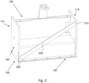
- Fig. 2 illustrates an embodiment of a screed body partition 100 according to the invention.
- the screed body partition 100 can be part of a paving screed 2 as well as part of a paving screed extension or a paving screed broadening part.
- the screed body partition 100 has one cross strut herein extending at a back side 102 of the screed body partition 100 from a centered part 110 to an outer part 120 of the screed body partition.
- An outer end 220 of the cross strut 200 which is arranged at the outer part 120 of the screed body partition, is positioned closer to a bottom side 105 of the paving screed 2 facing a pavement than an inner end 210 of the cross strut 200 arranged at the centered part 110 of the screed body partition 100.
- the cross strut 200 transforms a bending of the screed body partition 100 in horizontal direction into a twisting.
- the cross strut 200 in the shown embodiment is a massive and has a rectangular cross-section.
- the inner end 210 of the cross strut 200 is in the shown embodiment arranged at a position higher than a torsional centre of the screed body partition 100 and the outer end 220 of the at least one cross strut 200 is arranged at a position lower than the torsional centre of the screed body partition 100.
- the cross strut extends in a plane parallel to a front side 101 of the screed body partition.
- the at least cross strut could further extend from a plane nearer to the front side to a plane nearer to a back side of the screed body partition.
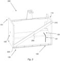
- Fig. 3 shows a further embodiment of a screed body partition 300 according to the invention.
- the screed body partition is mainly constructed as the screed body partition 100 of Fig. 2 . Therefore in the following merely the differences are described.
- the screed body partition 300 has a stabilizing angle sheet 130 extending from the centered part 110 of the screed body partition to the outer part 120 of the screed body partition.
- the cross sheet 130 has a recess 131.
- the recess 131 improves twisting by the cross strut 200 while on the other hand further stabilizing the screed body partition 300.
- Fig. 4A illustrates a further embodiment of a screed body partition 400 according to the invention.
- the cross strut 240 in the shown embodiment is an integral part of a sheet element of the screed body partition 100, here of a stabilizing angle sheet 140 of the screed body partition 400.
- the cross strut 240 here also extends at a back side 102 of the screed body partition 100 from a centered part 110 to an outer part 120 of the screed body partition.
- the outer end 220 of the at least one cross strut 200 which is arranged at the outer part 120 of the screed body partition, is positioned closer to a bottom side 105 of the paving screed 2 facing a pavement than the inner end 210 of the cross strut 200 arranged at the centered part 110 of the screed body partition 100.
- the cross strut 240 herein is arranged at an angle 10° with respect to the bottom side 105 of the paving screed 2.
- the cross strut 240 transforms a bending of the screed body partition 100 in horizontal direction into a twisting. This is further supported via the recess 141 in the stabilizing angle sheet 140.
- FIG. 4B is a schematic detail view of the stabilizing angle sheet 140 of the screed body partition 400 of Fig. 4A .
- the cross strut 240 can be built via removing material of the stabilizing angle sheet 140, for example via cutting before bending the sheet.
Landscapes
- Engineering & Computer Science (AREA)
- Architecture (AREA)
- Civil Engineering (AREA)
- Structural Engineering (AREA)
- Road Paving Machines (AREA)
Abstract
Description
- The invention relates to a paving screed, a paving screed extension, a paving screed broadening part and a paver.
- The invention is applicable on construction vehicles having a paving screed. In particular, the invention is applicable on pavers.
- During paving, the material (commonly asphalt) lies in front of the screed. The paver pulls the screed and the material is distributed, compacted and smoothed by the screed while the screed moves. The force of the material then causes the screed to deform. This is especially the case when bigger screed lengths are used. The force of the material onto the screed leads to an elastic deformation and the screed twists over the length because the material is normally only in touch with the lower end of the screed front surface.
- Such a deformation like twisting the screed changes the angle of attack and this leads to the effect that wide screeds tend to produce a lower thickness at the screed's ends.
- Today a screed tensioning device, a hydraulic cylinder which delivers constant force, is used to suppress such effects. The constant force of the hydraulic cylinder is used to pull the lower end of the screed so the deformation -caused by the material- can be removed. Typically screed tensioning is needed for screed lengths above 7 m. The location where the screed tensioning device is connected to can be changed. With this, the effect of the tensioning device can be adjusted for the paving lengths the tensioning device is needed for. This solution requires active parts like the hydraulic cylinder, which have to be maintained and controlled to function properly. Such solutions using cylinders are for example described in
CN102864726 . - In
CN203821207 a further possibility to improve bending and torsional strength in the paving screed is described using a reinforcing member between front and rear plate. - An object of the invention is to provide a paving screed or paving screed extension with an improved resistance to deformation preferably resulting in an evenly distribution of the paving material over the whole length of the paving screed.
- According to one aspect, the object is achieved by a paving screed according to
claim 1. - In particular, the paving screed has at least one screed body partition. The at least one screed body partition has at least one cross strut extending at a front side or at a back side of the screed body partition from a centered part to an outer part of the screed body partition. Thereby an outer end of the at least one cross strut arranged at the outer part of the screed body partition is positioned closer to a bottom side of the paving screed facing a pavement than an inner end of the at least one cross strut arranged at the centered part of the screed body partition. The cross strut transforms a bending of the screed body partition in horizontal direction into a twisting.
- The invention is based on the recognition that with the aid of the cross strut in the screed body partition a bending in horizontal direction of the screed caused by the force of the paving material can be used to induce twisting in the screed body and this twisting serves as a compensatory movement resulting in an even pavement facing surface of the paving screed and thus in evenly distributed material. Thus deformation in horizontal direction is transformed into a useful compensatory twisting movement. The invention further includes the recognition that this effect is achieved only by the arrangement of the cross strut obliquely from above at a centered part to bottom at an outer part. Thus by inducing the twisting the cross strut lifts the outer end of the screed body partition to level the height of the pavement facing surface of the paving screed. No active components are needed for the compensatory movement. The construction produces the correction from the external load. Thus a further advantage of the invention is that more external load (by more material) will lead to more corrective twisting against the bad influence of more material. In other words the paving screed according to the invention will care for itself by design without further adjustments needed.
- In the following further embodiments of the paving screed are described, which can be combined if not described as alternatives.
- According to one embodiment of the paving screed the inner end of the at least one cross strut is arranged at a position higher than a torsional centre of the screed body partition and the outer end of the at least one cross strut is arranged at a position lower than the torsional centre of the screed body partition. This leads to a further improved compensatory movement.
- In a further embodiment the at least cross strut further extends from a plane nearer to the front side to a plane nearer to a back side of the screed body partition. Such an arrangement may in particular be useful for application with restricted installation space. Alternatively the at least one cross strut extends in a plane parallel to a front side of the screed body partition. This arrangement results in higher twisting and is thus normally preferred.
- In a further embodiment the screed body partition is a main single screed section or one section of a main multiple sections screed or a screed extension, which is arranged behind and adjacent to a main screed section or a screed broadening part, which is arranged flanking to a main screed section. The arrangement of at least one cross strut in all of this sections or part of a paving screed may be useful. Furthermore also combinations of several cross struts in the different sections and or parts lead to a further improved complementary movement. Preferably in a paving screed having multiple sections, each of the multiple sections has at least one cross strut.
- In a further embodiment in the screed body partition a first cross strut extends at a front side and a second cross strut extends at a back side of the screed body partition.
- Preferably the at least one cross strut is arranged at an angle in the range of 10 to 85° with respect to the bottom side of the paving screed.
- In an embodiment of the paving screed the at least one cross strut comprises several single struts. Alternatively the at least one cross strut is massive or has a hollow structure, having for example a round, oval or polygonal cross-section. For example a tube can be used. The cross-section of the cross strut has to be designed sufficiently large to ensure buckling safety and on the other hand sufficiently small to allow twisting.
- In a further embodiment the cross strut is an integral part of a sheet element of the screed body partition, especially of a stabilizing angle sheet of the screed body partition. Thus the cross strut can be integrated in further components of the screed body.
- According to a further embodiment in a paving screed having a stabilizing angle sheet extending from the centered part of the screed body partition to the outer part of the screed body partition, the cross sheet has at least one recess. This embodiment enables an improved twisting.
- According to a further embodiment in a paving screed having two screed body partitions, each with at least one cross strut and being built up symmetrically, one of the two screed body partitions with at least one cross strut is arranged preferably in a left part of the paving screed while the other is arranged in a corresponding right part of the paving screed.
- According to a second aspect of the invention, the object is achieved by a paving screed extension according to claim 12. The paving screed extension is able to be arranged behind and adjacent to a main screed section and has at least one screed body partition. The at least one screed body partition has at least one cross strut extending at a front side or at a back side of the screed body partition from a centered part to an outer part of the screed body partition, wherein an outer end of the at least one cross strut arranged at the outer part of the screed body partition is positioned closer to a bottom side of the screed facing the pavement than an inner end of the at least one cross strut arranged at the centered part of the screed body partition, the cross strut transforming a bending of the screed body partition in horizontal direction into a twisting.
- Furthermore, according to a third aspect the object is achieved by a paving screed broadening part, which is able to be arranged flanking to a main screed section and has at least one screed body partition. The at least one screed body partition has at least one cross strut extending at a front side or at a back side of the screed body partition from a centered part to an outer part of the screed body partition, wherein an outer end of the at least one cross strut arranged at the outer part of the screed body partition is positioned closer to a bottom side of the screed facing the pavement than an inner end of the at least one cross strut arranged at the centered part of the screed body partition, the cross strut transforming a bending of the screed body partition in horizontal direction into a twisting.
- According to a fourth aspect of the invention, the object is achieved by a paver according to claim 14. The paver has a paving screed according to the first aspect or a paving screed broadening part according to the second aspect or a paving screed extension according to the third aspect of the invention.
- As to the advantages, preferred embodiments and details of the paving screed extension, the paver broadening part and the paver, reference is made to the corresponding aspect and embodiments described herein above with respect to the paving screed.
- Further advantages and advantageous features of the invention are disclosed in the following description and in the dependent claims.
- With reference to the appended drawings, below follows a more detailed description of embodiments of the invention cited as examples.
- In the drawings
-
Fig. 1 is a schematic view of an embodiment of a paver according to the fourth aspect of the invention, -
Fig. 2 is a schematic view of an embodiment of a screed body partition according to the invention, -
Fig. 3 is a schematic view of a further embodiment of a screed body partition according to the invention, -
Fig. 4A is a schematic view of a further embodiment of a screed body partition according to the invention, -
Fig. 4B is a schematic detail view of the stabilizing angle sheet of the screed body partition ofFig. 4A . - The present invention will now be described more fully hereinafter with reference to the accompanying drawings, in which exemplary embodiments of the invention are shown. The invention may, however, be embodied in many different forms and should not be construed as limited to the embodiments set forth herein; rather, these embodiments are provided for thoroughness and completeness. The skilled person will recognize that many changes and modifications may be made within the scope of the appended claims.
- Like reference character refer to like elements throughout the description.
-
Fig. 1 illustrates an embodiment of apaver 1 with apaving screed 2 according to the invention. Details of the paving screed construction especially regarding a cross strut will be discussed and shown with respect toFig. 2 to Fig. 4B . The shown paver is a trackedpaver 1 which accordingly comprises caterpillar tracks 9 for providing vehicle propulsion for thepaver 1. Furthermore, thepaver machine 1 comprises ahopper 3 in which road material is temporarily stored during paving. The road material is typically added to thehopper 3 from a truck. The road material may be asphalt. - The
paver 1 further comprises apaving screed 2 arranged at the rear of thepaver 1. Thepaving screed 2 is arranged to level out road material 4 disposed on the ground 5 in front of thepaving screed 2. The road material 4 has been transported from thehopper 3 to the ground via conveyor belts (not shown). Thepaving screed 2 has severalscreed body partitions 100. The road material applies forces especially to thefront side 101 of eachscreed body partition 100 causing bending of the screed body partition. With the aid of one cross strut (not shown) in eachscreed body partition 100 such a bending of thescreed body partition 100 in horizontal direction is transformed into a twisting resulting in evenly distributed road material over the full length of the screed body partition and thus also the paving screed. The at least one cross strut therefor extends at afront side 101 of thescreed body partition 100 from acentered part 110 to anouter part 120 of the screed body partition. An outer end of the at least onecross strut 200 is arranged at theouter part 120 of the screed body partition and is positioned closer to a bottom side of thepaving screed 2 facing a pavement than an inner end of the at having least onecross strut 200 being arranged at thecentered part 110 of thescreed body partition 100. In the shown embodiment eachscreed body partition 100 has one cross strut, thus thepaving screed 2 is built up symmetrically having cross struts on the left and right side of thepaving screed 2. In further embodiments also configurations with cross struts in the outer screed body partition are possible for example. The needed number of screed body partitions with cross struts depends on the overall construction and intrinsic stability against bending of the paving screed as well as on the length of the paving screed. The longer the paving screed, the more screed body partitions with cross struts are normally useful to compensate the bending. - In the shown embodiment of a paver a pressure actuated
screed lifting cylinder 6 is arranged to lift and lower thescreed 2 with respect to the ground 5. The pressure actuatedscreed lifting cylinder 6 is connected to ascreed lifting arm 7. Thescreed lifting arm 7 is connected to thescreed 2 at an end portion of the liftingscreed lifting arm 7. A further pressure actuatedscreed levelling cylinder 13 is arranged further to the front of thepaver 1 than the pressure actuatedscreed lifting cylinder 6. The pressure actuatedscreed levelling cylinder 13 is pivotally connected to thescreed lifting arm 7 at its other end portion. -
Fig. 2 illustrates an embodiment of ascreed body partition 100 according to the invention. Thescreed body partition 100 can be part of apaving screed 2 as well as part of a paving screed extension or a paving screed broadening part. Thescreed body partition 100 has one cross strut herein extending at aback side 102 of thescreed body partition 100 from acentered part 110 to anouter part 120 of the screed body partition. Anouter end 220 of thecross strut 200, which is arranged at theouter part 120 of the screed body partition, is positioned closer to abottom side 105 of thepaving screed 2 facing a pavement than aninner end 210 of thecross strut 200 arranged at thecentered part 110 of thescreed body partition 100. Thecross strut 200 transforms a bending of thescreed body partition 100 in horizontal direction into a twisting. Thecross strut 200 in the shown embodiment is a massive and has a rectangular cross-section. Theinner end 210 of thecross strut 200 is in the shown embodiment arranged at a position higher than a torsional centre of thescreed body partition 100 and theouter end 220 of the at least onecross strut 200 is arranged at a position lower than the torsional centre of thescreed body partition 100. In the shown embodiment the cross strut extends in a plane parallel to afront side 101 of the screed body partition. Alternatively the at least cross strut could further extend from a plane nearer to the front side to a plane nearer to a back side of the screed body partition. -
Fig. 3 shows a further embodiment of ascreed body partition 300 according to the invention. The screed body partition is mainly constructed as thescreed body partition 100 ofFig. 2 . Therefore in the following merely the differences are described. Thescreed body partition 300 has a stabilizingangle sheet 130 extending from thecentered part 110 of the screed body partition to theouter part 120 of the screed body partition. In the shown embodiment thecross sheet 130 has arecess 131. Therecess 131 improves twisting by thecross strut 200 while on the other hand further stabilizing thescreed body partition 300. -
Fig. 4A illustrates a further embodiment of ascreed body partition 400 according to the invention. Thecross strut 240 in the shown embodiment is an integral part of a sheet element of thescreed body partition 100, here of a stabilizingangle sheet 140 of thescreed body partition 400. Thecross strut 240 here also extends at aback side 102 of thescreed body partition 100 from acentered part 110 to anouter part 120 of the screed body partition. Theouter end 220 of the at least onecross strut 200, which is arranged at theouter part 120 of the screed body partition, is positioned closer to abottom side 105 of thepaving screed 2 facing a pavement than theinner end 210 of thecross strut 200 arranged at thecentered part 110 of thescreed body partition 100. Thecross strut 240 herein is arranged at an angle 10° with respect to thebottom side 105 of thepaving screed 2. Thecross strut 240 transforms a bending of thescreed body partition 100 in horizontal direction into a twisting. This is further supported via therecess 141 in the stabilizingangle sheet 140. With the integration of thecross strut 240 in the stabilizingangle sheet 141 the installation space in the screed body partition can be exploited optimally.Fig. 4B is a schematic detail view of the stabilizingangle sheet 140 of thescreed body partition 400 ofFig. 4A . In the detail view the arrangement ofrecess 141 andcross strut 240 can be seen. Thecross strut 240 can be built via removing material of the stabilizingangle sheet 140, for example via cutting before bending the sheet. -
- 1
- paver
- 2
- paving screed
- 3
- hopper
- 4
- road material
- 5
- ground
- 6
- screed lifting cylinder
- 7
- screed lifting arm
- 9
- caterpillar tracks
- 13
- screed levelling cylinder
- 100
- screed body partition
- 101
- front side
- 102
- backside
- 105
- bottom side
- 110
- inner part
- 120
- outer part
- 130
- stabilizing angle sheet
- 131
- recess
- 140
- stabilizing angle sheet
- 141
- recess
- 200
- cross strut
- 210
- inner end
- 220
- outer end
- 240
- cross strut
- 300
- screed body partition
- 400
- screed body partition
Claims (14)
- Paving screed (2) having at least one screed body partition (100), the at least one screed body partition (100) having at least one cross strut (200) extending at a front side (101) or at a back side (102) of the screed body partition (100) from a centered part (110) to an outer part (120) of the screed body partition, wherein an outer end (220) of the at least one cross strut (200) arranged at the outer part (120) of the screed body partition is positioned closer to a bottom side (105) of the paving screed (2) facing a pavement than an inner end (210) of the at least one cross strut (200) arranged at the centered part (110) of the screed body partition (100), the cross strut (200) transforming a bending of the screed body partition in horizontal direction into a twisting.
- Paving screed (2) according to claim 1, wherein the inner end (210) of the at least one cross strut (200) is arranged at a position higher than a torsional centre of the screed body partition (100) and the outer end (220) of the at least one cross strut (200) is arranged at a position lower than the torsional centre of the screed body partition (100).
- Paving screed (2) according to any of the preceding claims, wherein the at least cross strut (100) further extends from a plane nearer to the front side (101) to a plane nearer to a back side (102) of the screed body partition or extends in a plane parallel to a front side (101) of the screed body partition.
- Paving screed (2) according to any of the preceding claims wherein the screed body partition (100) is a main single screed section or one section of a main multiple sections screed or a screed extension, which is arranged behind and adjacent to a main screed section or a screed broadening part, which is arranged flanking to a main screed section.
- Paving screed (2) according to any of the preceding claims having multiple sections, wherein each of the multiple sections has at least one cross strut (200).
- Paving screed (2) according to any of the preceding claims, wherein the at least one cross strut (200) is arranged at an angle in the range of 10 to 85° with respect to the bottom side (105) of the paving screed (2).
- Paving screed (2) according to any of the preceding claims, wherein the at least one cross strut (200) comprises several single struts.
- Paving screed (2) according to any of claims 1 to 6, wherein the at least one cross strut (200) is massive or has a hollow structure and has a round, oval or polygonal cross-section.
- Paving screed (2) according to any of the preceding claims, wherein the cross strut (240) is an integral part of a sheet element (140) of the screed body partition (100), especially of a stabilizing angle sheet (140) of the screed body partition.
- Paving screed (2) according to any of the preceding claims having a stabilizing angle sheet (130, 140) extending from the centered part of the screed body partition to the outer part of the screed body partition, wherein the cross sheet (130, 140) has at least one recess (131, 141).
- Paving screed (2) according to any of the preceding claims having two screed body partitions (100) with at least one cross strut (200), wherein the paving screed is built up symmetrically and one of the two screed body partitions with at least one cross strut is arranged in a left part of the paving screed while the other is arranged in a corresponding right part of the paving screed.
- Paving screed extension able to be arranged behind and adjacent to a main screed section and having at least one screed body partition (100), the at least one screed body partition having at least one cross strut (200) extending at a front side or at a back side of the screed body partition from a centered part to an outer part of the screed body partition, wherein an outer end of the at least one cross strut arranged at the outer part of the screed body partition is positioned closer to a bottom side of the screed facing the pavement than an inner end of the at least one cross strut arranged at the centered part of the screed body partition, the cross strut transforming a bending of the screed body partition in horizontal direction into a twisting.
- Paving screed broadening part able to be arranged flanking to a main screed section and having at least one screed body partition, the at least one screed body partition (100) having at least one cross strut (200) extending at a front side or at a back side of the screed body partition from a centered part to an outer part of the screed body partition, wherein an outer end of the at least one cross strut arranged at the outer part of the screed body partition is positioned closer to a bottom side of the screed facing the pavement than an inner end of the at least one cross strut arranged at the centered part of the screed body partition, the cross strut transforming a bending of the screed body partition in horizontal direction into a twisting.
- Paver (1) having a paving screed (2) according to any of the claims 1 to 11 or a paving screed broadening part according to claim 12 or a paving screed extension according to claim 13.
Priority Applications (2)
| Application Number | Priority Date | Filing Date | Title |
|---|---|---|---|
| EP22173776.0A EP4279657A1 (en) | 2022-05-17 | 2022-05-17 | A paving screed, a paving screed extension, a paving screed broadening part and a paver |
| US18/136,937 US20230374742A1 (en) | 2022-05-17 | 2023-04-20 | Paving screed, a paving screed extension, a paving screed broadening part and a paver |
Applications Claiming Priority (1)
| Application Number | Priority Date | Filing Date | Title |
|---|---|---|---|
| EP22173776.0A EP4279657A1 (en) | 2022-05-17 | 2022-05-17 | A paving screed, a paving screed extension, a paving screed broadening part and a paver |
Publications (1)
| Publication Number | Publication Date |
|---|---|
| EP4279657A1 true EP4279657A1 (en) | 2023-11-22 |
Family
ID=81748646
Family Applications (1)
| Application Number | Title | Priority Date | Filing Date |
|---|---|---|---|
| EP22173776.0A Pending EP4279657A1 (en) | 2022-05-17 | 2022-05-17 | A paving screed, a paving screed extension, a paving screed broadening part and a paver |
Country Status (2)
| Country | Link |
|---|---|
| US (1) | US20230374742A1 (en) |
| EP (1) | EP4279657A1 (en) |
Cited By (1)
| Publication number | Priority date | Publication date | Assignee | Title |
|---|---|---|---|---|
| US20230374742A1 (en) * | 2022-05-17 | 2023-11-23 | Volvo Construction Equipment Ab | Paving screed, a paving screed extension, a paving screed broadening part and a paver |
Citations (3)
| Publication number | Priority date | Publication date | Assignee | Title |
|---|---|---|---|---|
| US4806047A (en) * | 1988-02-23 | 1989-02-21 | Morrison Donald R | Screed frame and stiffening apparatus |
| CN102864726A (en) | 2012-09-25 | 2013-01-09 | 中联重科股份有限公司 | Mechanically extended screed and assembly method of mechanically extended screed |
| CN203821207U (en) | 2013-12-10 | 2014-09-10 | 湖南三一路面机械有限公司 | Screed and paver |
Family Cites Families (3)
| Publication number | Priority date | Publication date | Assignee | Title |
|---|---|---|---|---|
| US8517630B2 (en) * | 2011-12-06 | 2013-08-27 | Caterpillar Paving Products Inc. | Screed plate arrangement and method of attaching a screed plate |
| US9074329B2 (en) * | 2013-05-02 | 2015-07-07 | Caterpillar Paving Products Inc. | Screed extension sliding support system |
| EP4279657A1 (en) * | 2022-05-17 | 2023-11-22 | Volvo Construction Equipment AB | A paving screed, a paving screed extension, a paving screed broadening part and a paver |
-
2022
- 2022-05-17 EP EP22173776.0A patent/EP4279657A1/en active Pending
-
2023
- 2023-04-20 US US18/136,937 patent/US20230374742A1/en active Pending
Patent Citations (3)
| Publication number | Priority date | Publication date | Assignee | Title |
|---|---|---|---|---|
| US4806047A (en) * | 1988-02-23 | 1989-02-21 | Morrison Donald R | Screed frame and stiffening apparatus |
| CN102864726A (en) | 2012-09-25 | 2013-01-09 | 中联重科股份有限公司 | Mechanically extended screed and assembly method of mechanically extended screed |
| CN203821207U (en) | 2013-12-10 | 2014-09-10 | 湖南三一路面机械有限公司 | Screed and paver |
Cited By (1)
| Publication number | Priority date | Publication date | Assignee | Title |
|---|---|---|---|---|
| US20230374742A1 (en) * | 2022-05-17 | 2023-11-23 | Volvo Construction Equipment Ab | Paving screed, a paving screed extension, a paving screed broadening part and a paver |
Also Published As
| Publication number | Publication date |
|---|---|
| US20230374742A1 (en) | 2023-11-23 |
Similar Documents
| Publication | Publication Date | Title |
|---|---|---|
| US20230374742A1 (en) | Paving screed, a paving screed extension, a paving screed broadening part and a paver | |
| ITRM960639A1 (en) | MOTOR VEHICLE FORWARD STRUCTURE | |
| US20030113166A1 (en) | Paver for the paving of ground courses for roads or the like | |
| CN114687404B (en) | Combined structure of construction machinery | |
| CN100503316C (en) | Cab support | |
| WO2015160707A1 (en) | Fender mounting system | |
| EP2765241A1 (en) | Earth-moving apparatus for construction machinery | |
| CN111573532B (en) | Folding suspension counterweight guide device for crane | |
| EP2766218A1 (en) | Lift gate system with extension plate and a lift gate platform | |
| EP3692213B1 (en) | A screed arrangement | |
| CN110573679A (en) | Column for vehicle cab | |
| KR101763830B1 (en) | Concrete pump car having subsidiary outrigger | |
| JP5205945B2 (en) | Resin back door reinforcement structure | |
| JPH0738400Y2 (en) | Shrub board device | |
| CN111663410B (en) | Hardened flattened extension tube | |
| CN105174091B (en) | Telescopic cantilever and crane | |
| JP4814798B2 (en) | Impact bar for pedestrians | |
| JP5818615B2 (en) | Road leveling machine leveling equipment | |
| KR20050015054A (en) | Composite steel with wave plate web and prestressed flange | |
| KR20150086599A (en) | Apparatus for connecting gap of bridge | |
| KR100493447B1 (en) | Expansion joint for a bridge | |
| KR101183125B1 (en) | Stress ribbon bridge reducing the moment of the point by the lever structure and method constructing the stress Ribbon Bridge by the lever structure | |
| JP2008291443A (en) | Screed apparatus of paving construction machine | |
| KR20030037258A (en) | Continuous Prestress Expanding Girder Beam | |
| CN115198748A (en) | Loading guardrail pile driver |
Legal Events
| Date | Code | Title | Description |
|---|---|---|---|
| PUAI | Public reference made under article 153(3) epc to a published international application that has entered the european phase |
Free format text: ORIGINAL CODE: 0009012 |
|
| STAA | Information on the status of an ep patent application or granted ep patent |
Free format text: STATUS: THE APPLICATION HAS BEEN PUBLISHED |
|
| AK | Designated contracting states |
Kind code of ref document: A1 Designated state(s): AL AT BE BG CH CY CZ DE DK EE ES FI FR GB GR HR HU IE IS IT LI LT LU LV MC MK MT NL NO PL PT RO RS SE SI SK SM TR |
|
| STAA | Information on the status of an ep patent application or granted ep patent |
Free format text: STATUS: REQUEST FOR EXAMINATION WAS MADE |
|
| STAA | Information on the status of an ep patent application or granted ep patent |
Free format text: STATUS: EXAMINATION IS IN PROGRESS |
|
| 17P | Request for examination filed |
Effective date: 20240522 |
|
| RBV | Designated contracting states (corrected) |
Designated state(s): AL AT BE BG CH CY CZ DE DK EE ES FI FR GB GR HR HU IE IS IT LI LT LU LV MC MK MT NL NO PL PT RO RS SE SI SK SM TR |
|
| RIC1 | Information provided on ipc code assigned before grant |
Ipc: E01C 19/48 20060101AFI20240527BHEP |
|
| 17Q | First examination report despatched |
Effective date: 20240618 |
|
| RAP1 | Party data changed (applicant data changed or rights of an application transferred) |
Owner name: AMMANN SCHWEIZ AG |