EP4279396A1 - Component and electrical system for an aircraft, and method for connecting components - Google Patents
Component and electrical system for an aircraft, and method for connecting components Download PDFInfo
- Publication number
- EP4279396A1 EP4279396A1 EP22174685.2A EP22174685A EP4279396A1 EP 4279396 A1 EP4279396 A1 EP 4279396A1 EP 22174685 A EP22174685 A EP 22174685A EP 4279396 A1 EP4279396 A1 EP 4279396A1
- Authority
- EP
- European Patent Office
- Prior art keywords
- component
- connection
- electrical
- interfaces
- aircraft
- Prior art date
- Legal status (The legal status is an assumption and is not a legal conclusion. Google has not performed a legal analysis and makes no representation as to the accuracy of the status listed.)
- Granted
Links
Images

Classifications
-
- H—ELECTRICITY
- H01—ELECTRIC ELEMENTS
- H01H—ELECTRIC SWITCHES; RELAYS; SELECTORS; EMERGENCY PROTECTIVE DEVICES
- H01H1/00—Contacts
- H01H1/58—Electric connections to or between contacts; Terminals
- H01H1/5822—Flexible connections between movable contact and terminal
-
- B—PERFORMING OPERATIONS; TRANSPORTING
- B64—AIRCRAFT; AVIATION; COSMONAUTICS
- B64D—EQUIPMENT FOR FITTING IN OR TO AIRCRAFT; FLIGHT SUITS; PARACHUTES; ARRANGEMENT OR MOUNTING OF POWER PLANTS OR PROPULSION TRANSMISSIONS IN AIRCRAFT
- B64D47/00—Equipment not otherwise provided for
-
- H—ELECTRICITY
- H01—ELECTRIC ELEMENTS
- H01H—ELECTRIC SWITCHES; RELAYS; SELECTORS; EMERGENCY PROTECTIVE DEVICES
- H01H1/00—Contacts
- H01H1/0094—Switches making use of nanoelectromechanical systems [NEMS]
-
- B—PERFORMING OPERATIONS; TRANSPORTING
- B64—AIRCRAFT; AVIATION; COSMONAUTICS
- B64D—EQUIPMENT FOR FITTING IN OR TO AIRCRAFT; FLIGHT SUITS; PARACHUTES; ARRANGEMENT OR MOUNTING OF POWER PLANTS OR PROPULSION TRANSMISSIONS IN AIRCRAFT
- B64D2221/00—Electric power distribution systems onboard aircraft
-
- H—ELECTRICITY
- H01—ELECTRIC ELEMENTS
- H01H—ELECTRIC SWITCHES; RELAYS; SELECTORS; EMERGENCY PROTECTIVE DEVICES
- H01H3/00—Mechanisms for operating contacts
- H01H2003/007—Mechanisms for operating contacts the contacts being actuated by deformation of a flexible housing
-
- H—ELECTRICITY
- H01—ELECTRIC ELEMENTS
- H01H—ELECTRIC SWITCHES; RELAYS; SELECTORS; EMERGENCY PROTECTIVE DEVICES
- H01H2207/00—Connections
- H01H2207/008—Adhesive means; Conductive adhesive
-
- H—ELECTRICITY
- H01—ELECTRIC ELEMENTS
- H01H—ELECTRIC SWITCHES; RELAYS; SELECTORS; EMERGENCY PROTECTIVE DEVICES
- H01H2300/00—Orthogonal indexing scheme relating to electric switches, relays, selectors or emergency protective devices covered by H01H
- H01H2300/036—Application nanoparticles, e.g. nanotubes, integrated in switch components, e.g. contacts, the switch itself being clearly of a different scale, e.g. greater than nanoscale
Definitions
- the present invention is directed to a component for an aircraft, an electrical system for an aircraft, and a method for connecting components.
- the present invention aims to reduce the spatial and weight requirements of components to be installed in an aircraft, in particular components comprising electrical features.
- a first aspect of the invention provides a component for an aircraft, the component comprising at least one connection interface, wherein the connection interface is configured to simultaneously establish an electrical connection and a mechanical connection.
- a further aspect of the invention provides an electrical system for an aircraft, the electrical system comprising a first component according to the first aspect of the invention and a second component according to the first aspect of the invention, wherein the first component and second component are electrically and mechanically connected by at least one first connection interface of the first component and at least one first connection interface of the second component.
- a further aspect of the invention provides a method for connecting a first component for an aircraft and a second component for an aircraft, wherein the method comprises the method step of simultaneously establishing an electrical connection and a mechanical connection between the components at a first pair of connection interfaces of the first component and the second component.
- One idea of the present invention lies in combining the electrical connection and the mechanical connection into one singular connection. In this way, no separate means of establishing the electrical connection and the mechanical connection respectively are needed, advantageously reducing the space and weight of the components and thereby the space and weight required by the electrical system.
- the at least one connection interface is further configured to easily release the electrical connection and the mechanical connection. This allows for advantageously easy replacement of components after initial installation.
- the at least one connection interface comprises nano wires.
- Nano wires provide advantageous properties for establishing electrical and mechanical connections, as explained in further detail in a later part of the present description.
- the component comprises a flexible material. This can provide an advantage during installation of the component, depending on its dimensions.
- the at least one first connection interface of the first component and the at least one first connection interface of the second component are connected by a connector, in particular by a foil comprising nano wires or by a conductive adhesive. This allows for an advantageously simplified fabrication of the components.
- the first component and the second component each comprise a plurality of connection interfaces and are mechanically connected by at least one second connection interface of the first component and at least one second connection interface of the second component. In this way, the mechanical stability of the connection can be further improved.
- the first component and the second component are further connected by an adhesive. In this way, the mechanical stability of the connection can be further improved.
- the step of simultaneously establishing the electrical connection and mechanical connection comprises an application of at least one of pressure, heat, and electrical current to the first pair of connection interfaces.
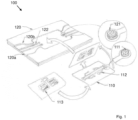
- Fig. 1 shows an electrical system 100 according to an embodiment of the invention in a pre-assembled state, wherein a first component 110 of the electrical system 100 is shown at different points in time.
- the electrical system 100 comprises a first component 110 and a second component 120.
- the first component 110 takes the form of a circuit board
- the second component takes the form of a cabin panel built of a composite material.
- the first component 110 comprises a plurality of connection interfaces 111, one of which is shown in an exploded view, an electronic circuit 112, and functional areas 113 on a side opposite to the side, on which the connection interfaces 111 and the electronic circuit 112 are arranged.
- the second component 120 comprises a plurality of connection interfaces 121, one of which is shown in an exploded view, and an electronic circuit 122.
- the second component 120 further comprises a first ply 120a on which the connection interfaces 121 and the electronic circuit 122 are arranged, and a second ply 120b, which forms a cover ply to the first ply 120a.
- the second ply 120b comprises a cut-out area granting access to the connection interfaces 121 and the electronic circuit 122.
- connection interfaces 111 of the first component 110 and the connection interfaces 121 of the second component 120 comprise nano wires arranged within a circular area, and are connected to the electronic circuits 112 and 122 respectively.
- the connection interfaces 111 of the first component 110 and the connection interfaces 121 of the second component 120 are arranged such that when the first component 110 is placed into the cut-out area of the second component 120, at least some of the connection interfaces 111 of the first component 110 overlap at least some of the connection interfaces 121 of the second component 120.
- connection interfaces 111 and 121 of the first component 110 and second component 120 contact each other, their respective nano wires can be connected through the application of pressure, heat, or electrical current, thereby establishing both an electrical connection and a mechanical connection simultaneously.
- a nano wire is a nano structure with the diameter of the order of a nano meter and that exhibits length-to-width ratios of 1000 or more. They can be manufactured top-down or bottom-up and can be made of different materials such as silver, nickel, tin selenide, etc. Nano wires can display considerable mechanical and electrical properties, in particular for establishing connection. Due to the extremely high surface area of the many nano wires, the inter diffusion process of atoms between neighboring nano wires can lead to immediate welding within a few milliseconds, even at room temperatures. Consequently, the two components form a strong mechanical joint which is at the same time a very good electrical connection and also highly thermally conductive. If electrical current is utilized to facilitate the welding process, the electrical connection can be directly tested during its establishing.
- connection between the nano wires can be temporarily loosened by applying heat and/or electrical current. This can be facilitated if an adhesive is involved in the connection process. In this way, the connection between the components can be easily severed and, for example, the first component can be replaced.
- the first component 110 shown in Figure 1 comprises at least some connection interfaces 111 which have no complement on the second component 120.
- the first component 110 can be configured to be connected to other components which may have a different layout of connection interfaces than the second component shown in Figure 1 .
- said connection interfaces 111 without direct complement could also be used to establish a mechanical connection between the first component 110 and the second component 120 without establishing an electrical connection.
- Fig. 2 shows an electrical system 100 according to a further embodiment of the invention during assembly.
- the electrical system 100 comprises a first component 130 and a second component 140.
- the first component 130 takes the form of a functional decor foil
- the second 140 component takes the form of a cabin panel.
- the first component 130 comprises a plurality of connection interfaces 131, one of which is shown in an exploded view, an electronic circuit 132, and functional areas 133 on a side opposite to the side on which the connection interfaces 131 and the electronic circuit 132 are arranged.
- the second component 140 comprises a plurality of connection interfaces 141 and an electronic circuit 142.
- connection interfaces 131 of the first component 1 130 and the connection interfaces 141 of the second component 140 comprise nano wires arranged within a circular area, and are connected to the electronic circuits 132 and 142 respectively.
- the connection interfaces 131 of the first component 130 and the connection interfaces 141 of the second component 140 are arranged such that when the first component 130 is placed on top of the second component 140, at least some of the connection interfaces 131 of the first component 130 overlap at least some of the connection interfaces 141 of the second component 140.
- connection interfaces 131 and 141 of the first component 130 and second component 140 contact each other, their respective nano wires can be connected through the application of pressure, heat, or electrical current, thereby establishing both an electrical connection and a mechanical connection simultaneously.
- the first component 130 shown in Figure 2 comprises a flexible material and can be bent during installation in such a way, that not all connection interfaces 131 of the first component 130 come into contact with their complementary connection interfaces 141 of the second component 140. This can lead to an easier installation of the first component 130 with respect to the second component 140, in particular if the first component 130 exceeds a certain length and/or width, compared to e.g. the components shown in Figure 1 , which are relatively compact, and which can therefore benefit from comprising rigid materials.
- nano wire bonding wherein corresponding pairs of connection interfaces comprise nano wires.
- corresponding pairs of connection interfaces comprise nano wires.
- This technology is advantageous as it provides beneficial properties concerning electrical and mechanical connectivity combined with a relative ease of processing.
- connection interfaces of the components could be provided with metal coatings or plates which are then connected using a thin foil comprising nano wires, in a process similar to the process used when connecting connection interfaces comprising nano wires. It is also possible to connect connection interfaces comprising metal coatings or plates using a conductive adhesive or by providing the connection interfaces with apertures which can receive a fastener, like a screw or a bolt, which advantageously comprises a metal to reinforce the electrical connection between the connection interfaces.
Landscapes
- Engineering & Computer Science (AREA)
- Physics & Mathematics (AREA)
- Electromagnetism (AREA)
- Chemical & Material Sciences (AREA)
- Nanotechnology (AREA)
- Aviation & Aerospace Engineering (AREA)
- Connections Effected By Soldering, Adhesion, Or Permanent Deformation (AREA)
- Structure Of Printed Boards (AREA)
Abstract
Description
- The present invention is directed to a component for an aircraft, an electrical system for an aircraft, and a method for connecting components.
- The current state of the art in electrical devices in aircrafts is based on separate electrical harness, analogue devices, and separate mechanical fastening of devices. For example, switches are attached on mounting plates, secured with fastener elements and connected via electrical cables.
- All these parts have to be manufactured separately, collected, and installed manually. The end result is a certain amount of cost for the parts, cost for the labor of installation, and a certain amount of weight and space for the installation. In aircrafts, especially weight and space of components is always something that is desirably reduced as much as possible.
- In view of the above, the present invention aims to reduce the spatial and weight requirements of components to be installed in an aircraft, in particular components comprising electrical features.
- According to the present invention, this problem is solved by a component with the features of independent claim 1, an electrical system with the features of independent claim 5, and a method with the features of independent claim 9.
- To that effect, a first aspect of the invention provides a component for an aircraft, the component comprising at least one connection interface, wherein the connection interface is configured to simultaneously establish an electrical connection and a mechanical connection.
- A further aspect of the invention provides an electrical system for an aircraft, the electrical system comprising a first component according to the first aspect of the invention and a second component according to the first aspect of the invention, wherein the first component and second component are electrically and mechanically connected by at least one first connection interface of the first component and at least one first connection interface of the second component.
- A further aspect of the invention provides a method for connecting a first component for an aircraft and a second component for an aircraft, wherein the method comprises the method step of simultaneously establishing an electrical connection and a mechanical connection between the components at a first pair of connection interfaces of the first component and the second component.
- One idea of the present invention lies in combining the electrical connection and the mechanical connection into one singular connection. In this way, no separate means of establishing the electrical connection and the mechanical connection respectively are needed, advantageously reducing the space and weight of the components and thereby the space and weight required by the electrical system.
- Advantageous embodiments and further developments are apparent from the further dependent claims and from the description with reference to the figures. According to a further embodiment of the component, the at least one connection interface is further configured to easily release the electrical connection and the mechanical connection. This allows for advantageously easy replacement of components after initial installation.
- According to a further embodiment of the component, the at least one connection interface comprises nano wires. Nano wires provide advantageous properties for establishing electrical and mechanical connections, as explained in further detail in a later part of the present description.
- According to a further embodiment of the component, the component comprises a flexible material. This can provide an advantage during installation of the component, depending on its dimensions.
- According to a further embodiment of the electrical system, the at least one first connection interface of the first component and the at least one first connection interface of the second component are connected by a connector, in particular by a foil comprising nano wires or by a conductive adhesive. This allows for an advantageously simplified fabrication of the components.
- According to a further embodiment of the electrical system, the first component and the second component each comprise a plurality of connection interfaces and are mechanically connected by at least one second connection interface of the first component and at least one second connection interface of the second component. In this way, the mechanical stability of the connection can be further improved.
- According to a further embodiment of the electrical system, the first component and the second component are further connected by an adhesive. In this way, the mechanical stability of the connection can be further improved.
- According to a further embodiment of the method, the step of simultaneously establishing the electrical connection and mechanical connection comprises an application of at least one of pressure, heat, and electrical current to the first pair of connection interfaces. This allows for an advantageously easy establishing of the connection and can even be utilized to test the electrical connection right away.
- The above embodiments and further developments can be combined with each other as desired, if useful. Further possible embodiments, further developments and implementations of the invention also comprise combinations of features of the invention described above or below with respect to the embodiments which are not explicitly mentioned. In particular, the person skilled in the art will also add individual aspects as improvements or additions to the respective basic form of the present invention.
- The present invention is explained in more detail below with reference to the embodiments shown in the schematic figures.
- Fig. 1
- shows a schematic illustration of an electrical system according to an embodiment of the invention in a pre-assembled state; and
- Fig. 2
- shows a schematic illustration of an electrical system according to a further embodiment of the invention during assembly.
- The accompanying figures are intended to provide a further understanding of embodiments of the invention. They illustrate embodiments and, in connection with the description, serve to explain principles and concepts of the invention. Other embodiments and many of the advantages mentioned will be apparent with reference to the drawings. The elements of the drawings are not necessarily shown to scale with respect to each other.
- In the figures of the drawings, identical elements, features and components that have the same function and the same effect are each given the same reference signs, unless otherwise specified.
-
Fig. 1 shows anelectrical system 100 according to an embodiment of the invention in a pre-assembled state, wherein afirst component 110 of theelectrical system 100 is shown at different points in time. - The
electrical system 100 comprises afirst component 110 and asecond component 120. In the embodiment shown, thefirst component 110 takes the form of a circuit board, and the second component takes the form of a cabin panel built of a composite material. Thefirst component 110 comprises a plurality ofconnection interfaces 111, one of which is shown in an exploded view, anelectronic circuit 112, andfunctional areas 113 on a side opposite to the side, on which theconnection interfaces 111 and theelectronic circuit 112 are arranged. Thesecond component 120 comprises a plurality ofconnection interfaces 121, one of which is shown in an exploded view, and anelectronic circuit 122. Thesecond component 120 further comprises afirst ply 120a on which theconnection interfaces 121 and theelectronic circuit 122 are arranged, and asecond ply 120b, which forms a cover ply to thefirst ply 120a. Thesecond ply 120b comprises a cut-out area granting access to theconnection interfaces 121 and theelectronic circuit 122. - In the embodiment shown, the
connection interfaces 111 of thefirst component 110 and theconnection interfaces 121 of thesecond component 120 comprise nano wires arranged within a circular area, and are connected to theelectronic circuits connection interfaces 111 of thefirst component 110 and theconnection interfaces 121 of thesecond component 120 are arranged such that when thefirst component 110 is placed into the cut-out area of thesecond component 120, at least some of theconnection interfaces 111 of thefirst component 110 overlap at least some of theconnection interfaces 121 of thesecond component 120. Whenconnection interfaces first component 110 andsecond component 120 contact each other, their respective nano wires can be connected through the application of pressure, heat, or electrical current, thereby establishing both an electrical connection and a mechanical connection simultaneously. - A nano wire is a nano structure with the diameter of the order of a nano meter and that exhibits length-to-width ratios of 1000 or more. They can be manufactured top-down or bottom-up and can be made of different materials such as silver, nickel, tin selenide, etc. Nano wires can display considerable mechanical and electrical properties, in particular for establishing connection. Due to the extremely high surface area of the many nano wires, the inter diffusion process of atoms between neighboring nano wires can lead to immediate welding within a few milliseconds, even at room temperatures. Consequently, the two components form a strong mechanical joint which is at the same time a very good electrical connection and also highly thermally conductive. If electrical current is utilized to facilitate the welding process, the electrical connection can be directly tested during its establishing.
- Another advantage of using nano wires is that the connection between the nano wires can be temporarily loosened by applying heat and/or electrical current. This can be facilitated if an adhesive is involved in the connection process. In this way, the connection between the components can be easily severed and, for example, the first component can be replaced.
- The
first component 110 shown inFigure 1 comprises at least someconnection interfaces 111 which have no complement on thesecond component 120. In this way, thefirst component 110 can be configured to be connected to other components which may have a different layout of connection interfaces than the second component shown inFigure 1 . Depending on the configuration of theconnection interfaces 111, saidconnection interfaces 111 without direct complement could also be used to establish a mechanical connection between thefirst component 110 and thesecond component 120 without establishing an electrical connection. -
Fig. 2 shows anelectrical system 100 according to a further embodiment of the invention during assembly. - The
electrical system 100 comprises afirst component 130 and asecond component 140. In the embodiment shown, thefirst component 130 takes the form of a functional decor foil, and the second 140 component takes the form of a cabin panel. Thefirst component 130 comprises a plurality ofconnection interfaces 131, one of which is shown in an exploded view, anelectronic circuit 132, andfunctional areas 133 on a side opposite to the side on which the connection interfaces 131 and theelectronic circuit 132 are arranged. Thesecond component 140 comprises a plurality ofconnection interfaces 141 and anelectronic circuit 142. - In the embodiment shown, the connection interfaces 131 of the first component 1 130 and the connection interfaces 141 of the
second component 140 comprise nano wires arranged within a circular area, and are connected to theelectronic circuits first component 130 and the connection interfaces 141 of thesecond component 140 are arranged such that when thefirst component 130 is placed on top of thesecond component 140, at least some of the connection interfaces 131 of thefirst component 130 overlap at least some of the connection interfaces 141 of thesecond component 140. When connection interfaces 131 and 141 of thefirst component 130 andsecond component 140 contact each other, their respective nano wires can be connected through the application of pressure, heat, or electrical current, thereby establishing both an electrical connection and a mechanical connection simultaneously. - The
first component 130 shown inFigure 2 comprises a flexible material and can be bent during installation in such a way, that not allconnection interfaces 131 of thefirst component 130 come into contact with theircomplementary connection interfaces 141 of thesecond component 140. This can lead to an easier installation of thefirst component 130 with respect to thesecond component 140, in particular if thefirst component 130 exceeds a certain length and/or width, compared to e.g. the components shown inFigure 1 , which are relatively compact, and which can therefore benefit from comprising rigid materials. - In
Figures 1 and2 , nano wire bonding, wherein corresponding pairs of connection interfaces comprise nano wires. has been shown as an example of simultaneously establishing an electrical connection and a mechanical connection. This technology is advantageous as it provides beneficial properties concerning electrical and mechanical connectivity combined with a relative ease of processing. However, it is also possible for only one of a corresponding pair of connection interfaces to comprise nano wires, as even when the corresponding partner comprises, for example, only a metal coating, a sufficiently secure electrical and mechanical connection can be established, depending on the configurations of the components to be connected. Foregoing nano wires on a component itself can lead to easier manufacturing of said component. Consequently, it is also possible that neither of the components comprises nano wires itself. It could be possible to provide the connection interfaces of the components with metal coatings or plates which are then connected using a thin foil comprising nano wires, in a process similar to the process used when connecting connection interfaces comprising nano wires. It is also possible to connect connection interfaces comprising metal coatings or plates using a conductive adhesive or by providing the connection interfaces with apertures which can receive a fastener, like a screw or a bolt, which advantageously comprises a metal to reinforce the electrical connection between the connection interfaces. - In
Figure 1 and2 , various examples of components for an aircraft have been shown. The present invention is not to be limited to these examples but is intended to cover any and all components of an aircraft for which a simultaneous electrical and mechanical connection can be conceived. -
- 100
- electrical system
- 110
- component; first component
- 111
- connection interface
- 112
- electronic circuit
- 113
- functional area
- 120
- component; second component
- 120a
- first ply
- 120b
- second ply
- 121
- connection interface
- 122
- electronic circuit
- 130
- component; first component
- 131
- connection interface
- 132
- electronic circuit
- 133
- functional area
- 140
- second component
- 141
- connection interface
- 142
- electronic circuit
Claims (15)
- Component (110;120;130;140) for an aircraft, the component (110;120;130;140) comprising at least one connection interface (111;121;131;141), wherein the connection interface (111;121;131;141) is configured to simultaneously establish an electrical connection and a mechanical connection.
- Component (110;120;130;140) according to claim 1, wherein the at least one connection interface (111;121;131;141) is further configured to easily release the electrical connection and the mechanical connection.
- Component (110;120;130;140) according to any one of claims 1 or 2, wherein the at least one connection interface (111;121;131;141) comprises nano wires.
- Component (110;120;130;140) according to any one of the preceding claims, wherein the component (110;120;130;140) comprises a flexible material.
- Electrical system for an aircraft, the electrical system comprising a first component (110;130) according to one of the preceding claims and a second component (120;140) according to one of the preceding claims, wherein the first component (110;130) and second component (120;140) are electrically and mechanically connected by at least one first connection interface (111;131) of the first component (110;130) and at least one first connection interface (121;141) of the second component (120;140).
- Electrical system according to claim 5, wherein the at least one first connection interface (111;131) of the first component (110;130) and the at least one first connection interface (121;141) of the second component (120;140) are connected by a connector, in particular by a foil comprising nano wires or by a conductive adhesive.
- Electrical system according to any one of claims 5 or 6, wherein the first component (110;130) and the second component (120;140) each comprise a plurality of connection interfaces (111;121;131;141) and are mechanically connected by at least one second connection interface (111;131) of the first component (110;130) and at least one second connection interface (121;141) of the second component (120;140).
- Electrical system according to any one of claims 5 to 7, wherein the first component (110;130) and the second component (120;140) are further connected by an adhesive.
- Method for connecting a first component (110;130) for an aircraft and a second component (120;140) for an aircraft, wherein the method comprises the method step of simultaneously establishing an electrical connection and a mechanical connection between the components at a first pair of connection interfaces (111;121;131;141) of the first component (110;130) and the second component (120;140).
- Method according to claim 9, wherein the first pair of connection interfaces (111;121;131;141) are further configured to easily release the electrical connection and the mechanical connection.
- Method according to any one of claims 9 or 10, wherein at least one of the first pair of connection interfaces (111;121;131;141) comprises nano wires.
- Method according to any one of claims 9 to 11, wherein at least one of the first component (110;130) or second component (120;140) comprises a flexible material.
- Method according to any one of claims 9 to 12, wherein the first pair of connection interfaces (111;121;131;141) are connected by a connector, in particular by a foil comprising nano wires or by a conductive adhesive.
- Method according to any one of claims 9 to 13, wherein the first component (110;130) and the second component (120;140) are further mechanically connected by a second pair of connection interfaces (111;121;131;141) of the first component (110;130) and the second component (120;140).
- Method according to any one of claims 9 to 14, wherein the step of simultaneously establishing the electrical connection and mechanical connection comprises an application of at least one of pressure, heat, and electrical current to the first pair of connection interfaces (111;121;131;141).
Priority Applications (2)
| Application Number | Priority Date | Filing Date | Title |
|---|---|---|---|
| EP22174685.2A EP4279396B1 (en) | 2022-05-20 | 2022-05-20 | Electrical system for an aircraft |
| US18/319,257 US20230377811A1 (en) | 2022-05-20 | 2023-05-17 | Component and electrical system for an aircraft, and method for connecting components |
Applications Claiming Priority (1)
| Application Number | Priority Date | Filing Date | Title |
|---|---|---|---|
| EP22174685.2A EP4279396B1 (en) | 2022-05-20 | 2022-05-20 | Electrical system for an aircraft |
Publications (2)
| Publication Number | Publication Date |
|---|---|
| EP4279396A1 true EP4279396A1 (en) | 2023-11-22 |
| EP4279396B1 EP4279396B1 (en) | 2025-07-02 |
Family
ID=82403742
Family Applications (1)
| Application Number | Title | Priority Date | Filing Date |
|---|---|---|---|
| EP22174685.2A Active EP4279396B1 (en) | 2022-05-20 | 2022-05-20 | Electrical system for an aircraft |
Country Status (2)
| Country | Link |
|---|---|
| US (1) | US20230377811A1 (en) |
| EP (1) | EP4279396B1 (en) |
Citations (3)
| Publication number | Priority date | Publication date | Assignee | Title |
|---|---|---|---|---|
| DE102006031322A1 (en) * | 2006-07-06 | 2007-09-27 | Siemens Ag | Electromechanical component |
| US10177471B2 (en) * | 2014-11-14 | 2019-01-08 | The Boeing Company | Composite and nanowire conduit |
| US10686300B2 (en) * | 2016-07-13 | 2020-06-16 | Zodiac Aero Electric | Device for electrically connecting power distribution plates and electrical power distribution system provided with such a connection device |
-
2022
- 2022-05-20 EP EP22174685.2A patent/EP4279396B1/en active Active
-
2023
- 2023-05-17 US US18/319,257 patent/US20230377811A1/en not_active Abandoned
Patent Citations (3)
| Publication number | Priority date | Publication date | Assignee | Title |
|---|---|---|---|---|
| DE102006031322A1 (en) * | 2006-07-06 | 2007-09-27 | Siemens Ag | Electromechanical component |
| US10177471B2 (en) * | 2014-11-14 | 2019-01-08 | The Boeing Company | Composite and nanowire conduit |
| US10686300B2 (en) * | 2016-07-13 | 2020-06-16 | Zodiac Aero Electric | Device for electrically connecting power distribution plates and electrical power distribution system provided with such a connection device |
Also Published As
| Publication number | Publication date |
|---|---|
| US20230377811A1 (en) | 2023-11-23 |
| EP4279396B1 (en) | 2025-07-02 |
Similar Documents
| Publication | Publication Date | Title |
|---|---|---|
| US10943740B2 (en) | Electrical connection contact for a ceramic component, a ceramic component, and a component arrangement | |
| DE10121970B4 (en) | Power semiconductor module in pressure contact | |
| EP0159593B1 (en) | Electrical connector and method for making the same | |
| US20110163569A1 (en) | Terminal mounting structure and method | |
| CN101364679A (en) | Electrical connection assembly | |
| US7568917B1 (en) | Laminated electrical contact strip | |
| JPH0275178A (en) | Cathode edge connector for solderless surface mounting | |
| US6927982B2 (en) | Method of connecting a device to a support, and pad for establishing a connection between a device and a support | |
| JPH01303709A (en) | Electrical product having contactor | |
| EP2467001B1 (en) | Circuit assembly with at least two sub-modules | |
| CN111052347B (en) | High-density multi-component and series-connected packages | |
| EP2340587A1 (en) | Terminal mounting structure and method | |
| EP4279396B1 (en) | Electrical system for an aircraft | |
| US10446297B2 (en) | Resistor | |
| US5106308A (en) | Planar contact grid array connector | |
| CN108461290A (en) | Electronic unit with metal terminal | |
| EP2685795A1 (en) | Circuit board and method for manufacturing circuit board | |
| US7385144B2 (en) | Method and apparatus for electrically connecting printed circuit boards or other panels | |
| US10840207B2 (en) | Line-integrated switch and method for producing a line-integrated switch | |
| US20250070494A1 (en) | Flexible Interconnect Circuits Comprising Spring Contacts | |
| EP0854667B1 (en) | Electronic control module | |
| DE102017217354A1 (en) | MULTILAYER POWER RAIL ARRANGEMENT AND POWER MODULE | |
| US10010017B2 (en) | Potential equalization in a control device for a motor vehicle | |
| US20130269183A1 (en) | Printed circuit board interconnect assembly and method | |
| US20150194756A1 (en) | Stress-minimising electrical through-contact |
Legal Events
| Date | Code | Title | Description |
|---|---|---|---|
| PUAI | Public reference made under article 153(3) epc to a published international application that has entered the european phase |
Free format text: ORIGINAL CODE: 0009012 |
|
| STAA | Information on the status of an ep patent application or granted ep patent |
Free format text: STATUS: THE APPLICATION HAS BEEN PUBLISHED |
|
| AK | Designated contracting states |
Kind code of ref document: A1 Designated state(s): AL AT BE BG CH CY CZ DE DK EE ES FI FR GB GR HR HU IE IS IT LI LT LU LV MC MK MT NL NO PL PT RO RS SE SI SK SM TR |
|
| STAA | Information on the status of an ep patent application or granted ep patent |
Free format text: STATUS: REQUEST FOR EXAMINATION WAS MADE |
|
| 17P | Request for examination filed |
Effective date: 20240220 |
|
| RBV | Designated contracting states (corrected) |
Designated state(s): AL AT BE BG CH CY CZ DE DK EE ES FI FR GB GR HR HU IE IS IT LI LT LU LV MC MK MT NL NO PL PT RO RS SE SI SK SM TR |
|
| GRAP | Despatch of communication of intention to grant a patent |
Free format text: ORIGINAL CODE: EPIDOSNIGR1 |
|
| STAA | Information on the status of an ep patent application or granted ep patent |
Free format text: STATUS: GRANT OF PATENT IS INTENDED |
|
| INTG | Intention to grant announced |
Effective date: 20241126 |
|
| GRAJ | Information related to disapproval of communication of intention to grant by the applicant or resumption of examination proceedings by the epo deleted |
Free format text: ORIGINAL CODE: EPIDOSDIGR1 |
|
| STAA | Information on the status of an ep patent application or granted ep patent |
Free format text: STATUS: REQUEST FOR EXAMINATION WAS MADE |
|
| GRAP | Despatch of communication of intention to grant a patent |
Free format text: ORIGINAL CODE: EPIDOSNIGR1 |
|
| STAA | Information on the status of an ep patent application or granted ep patent |
Free format text: STATUS: GRANT OF PATENT IS INTENDED |
|
| INTC | Intention to grant announced (deleted) | ||
| INTG | Intention to grant announced |
Effective date: 20250324 |
|
| GRAS | Grant fee paid |
Free format text: ORIGINAL CODE: EPIDOSNIGR3 |
|
| GRAA | (expected) grant |
Free format text: ORIGINAL CODE: 0009210 |
|
| STAA | Information on the status of an ep patent application or granted ep patent |
Free format text: STATUS: THE PATENT HAS BEEN GRANTED |
|
| AK | Designated contracting states |
Kind code of ref document: B1 Designated state(s): AL AT BE BG CH CY CZ DE DK EE ES FI FR GB GR HR HU IE IS IT LI LT LU LV MC MK MT NL NO PL PT RO RS SE SI SK SM TR |
|
| REG | Reference to a national code |
Ref country code: GB Ref legal event code: FG4D |
|
| REG | Reference to a national code |
Ref country code: CH Ref legal event code: EP |
|
| REG | Reference to a national code |
Ref country code: DE Ref legal event code: R096 Ref document number: 602022016714 Country of ref document: DE |
|
| REG | Reference to a national code |
Ref country code: IE Ref legal event code: FG4D |
|
| REG | Reference to a national code |
Ref country code: NL Ref legal event code: MP Effective date: 20250702 |
|
| PG25 | Lapsed in a contracting state [announced via postgrant information from national office to epo] |
Ref country code: PT Free format text: LAPSE BECAUSE OF FAILURE TO SUBMIT A TRANSLATION OF THE DESCRIPTION OR TO PAY THE FEE WITHIN THE PRESCRIBED TIME-LIMIT Effective date: 20251103 |
|
| PG25 | Lapsed in a contracting state [announced via postgrant information from national office to epo] |
Ref country code: NL Free format text: LAPSE BECAUSE OF FAILURE TO SUBMIT A TRANSLATION OF THE DESCRIPTION OR TO PAY THE FEE WITHIN THE PRESCRIBED TIME-LIMIT Effective date: 20250702 |
|
| REG | Reference to a national code |
Ref country code: AT Ref legal event code: MK05 Ref document number: 1809006 Country of ref document: AT Kind code of ref document: T Effective date: 20250702 |
|
| PG25 | Lapsed in a contracting state [announced via postgrant information from national office to epo] |
Ref country code: IS Free format text: LAPSE BECAUSE OF FAILURE TO SUBMIT A TRANSLATION OF THE DESCRIPTION OR TO PAY THE FEE WITHIN THE PRESCRIBED TIME-LIMIT Effective date: 20251102 |
|
| PG25 | Lapsed in a contracting state [announced via postgrant information from national office to epo] |
Ref country code: NO Free format text: LAPSE BECAUSE OF FAILURE TO SUBMIT A TRANSLATION OF THE DESCRIPTION OR TO PAY THE FEE WITHIN THE PRESCRIBED TIME-LIMIT Effective date: 20251002 |
|
| REG | Reference to a national code |
Ref country code: LT Ref legal event code: MG9D |
|
| PG25 | Lapsed in a contracting state [announced via postgrant information from national office to epo] |
Ref country code: AT Free format text: LAPSE BECAUSE OF FAILURE TO SUBMIT A TRANSLATION OF THE DESCRIPTION OR TO PAY THE FEE WITHIN THE PRESCRIBED TIME-LIMIT Effective date: 20250702 |
|
| PG25 | Lapsed in a contracting state [announced via postgrant information from national office to epo] |
Ref country code: FI Free format text: LAPSE BECAUSE OF FAILURE TO SUBMIT A TRANSLATION OF THE DESCRIPTION OR TO PAY THE FEE WITHIN THE PRESCRIBED TIME-LIMIT Effective date: 20250702 |
|
| PG25 | Lapsed in a contracting state [announced via postgrant information from national office to epo] |
Ref country code: HR Free format text: LAPSE BECAUSE OF FAILURE TO SUBMIT A TRANSLATION OF THE DESCRIPTION OR TO PAY THE FEE WITHIN THE PRESCRIBED TIME-LIMIT Effective date: 20250702 |
|
| PG25 | Lapsed in a contracting state [announced via postgrant information from national office to epo] |
Ref country code: GR Free format text: LAPSE BECAUSE OF FAILURE TO SUBMIT A TRANSLATION OF THE DESCRIPTION OR TO PAY THE FEE WITHIN THE PRESCRIBED TIME-LIMIT Effective date: 20251003 |
|
| PG25 | Lapsed in a contracting state [announced via postgrant information from national office to epo] |
Ref country code: CZ Free format text: LAPSE BECAUSE OF FAILURE TO SUBMIT A TRANSLATION OF THE DESCRIPTION OR TO PAY THE FEE WITHIN THE PRESCRIBED TIME-LIMIT Effective date: 20250702 Ref country code: SE Free format text: LAPSE BECAUSE OF FAILURE TO SUBMIT A TRANSLATION OF THE DESCRIPTION OR TO PAY THE FEE WITHIN THE PRESCRIBED TIME-LIMIT Effective date: 20250702 |
|
| PG25 | Lapsed in a contracting state [announced via postgrant information from national office to epo] |
Ref country code: LV Free format text: LAPSE BECAUSE OF FAILURE TO SUBMIT A TRANSLATION OF THE DESCRIPTION OR TO PAY THE FEE WITHIN THE PRESCRIBED TIME-LIMIT Effective date: 20250702 |
|
| PG25 | Lapsed in a contracting state [announced via postgrant information from national office to epo] |
Ref country code: PL Free format text: LAPSE BECAUSE OF FAILURE TO SUBMIT A TRANSLATION OF THE DESCRIPTION OR TO PAY THE FEE WITHIN THE PRESCRIBED TIME-LIMIT Effective date: 20250702 Ref country code: BG Free format text: LAPSE BECAUSE OF FAILURE TO SUBMIT A TRANSLATION OF THE DESCRIPTION OR TO PAY THE FEE WITHIN THE PRESCRIBED TIME-LIMIT Effective date: 20250702 |
|
| PG25 | Lapsed in a contracting state [announced via postgrant information from national office to epo] |
Ref country code: RS Free format text: LAPSE BECAUSE OF FAILURE TO SUBMIT A TRANSLATION OF THE DESCRIPTION OR TO PAY THE FEE WITHIN THE PRESCRIBED TIME-LIMIT Effective date: 20251002 |
|
| PG25 | Lapsed in a contracting state [announced via postgrant information from national office to epo] |
Ref country code: ES Free format text: LAPSE BECAUSE OF FAILURE TO SUBMIT A TRANSLATION OF THE DESCRIPTION OR TO PAY THE FEE WITHIN THE PRESCRIBED TIME-LIMIT Effective date: 20250702 |
|
| PG25 | Lapsed in a contracting state [announced via postgrant information from national office to epo] |
Ref country code: SM Free format text: LAPSE BECAUSE OF FAILURE TO SUBMIT A TRANSLATION OF THE DESCRIPTION OR TO PAY THE FEE WITHIN THE PRESCRIBED TIME-LIMIT Effective date: 20250702 |
|
| REG | Reference to a national code |
Ref country code: DE Ref legal event code: R097 Ref document number: 602022016714 Country of ref document: DE |
|
| PG25 | Lapsed in a contracting state [announced via postgrant information from national office to epo] |
Ref country code: DK Free format text: LAPSE BECAUSE OF FAILURE TO SUBMIT A TRANSLATION OF THE DESCRIPTION OR TO PAY THE FEE WITHIN THE PRESCRIBED TIME-LIMIT Effective date: 20250702 |
|
| PG25 | Lapsed in a contracting state [announced via postgrant information from national office to epo] |
Ref country code: IT Free format text: LAPSE BECAUSE OF FAILURE TO SUBMIT A TRANSLATION OF THE DESCRIPTION OR TO PAY THE FEE WITHIN THE PRESCRIBED TIME-LIMIT Effective date: 20250702 |
|
| PG25 | Lapsed in a contracting state [announced via postgrant information from national office to epo] |
Ref country code: EE Free format text: LAPSE BECAUSE OF FAILURE TO SUBMIT A TRANSLATION OF THE DESCRIPTION OR TO PAY THE FEE WITHIN THE PRESCRIBED TIME-LIMIT Effective date: 20250702 Ref country code: SK Free format text: LAPSE BECAUSE OF FAILURE TO SUBMIT A TRANSLATION OF THE DESCRIPTION OR TO PAY THE FEE WITHIN THE PRESCRIBED TIME-LIMIT Effective date: 20250702 |
|
| PLBE | No opposition filed within time limit |
Free format text: ORIGINAL CODE: 0009261 |
|
| STAA | Information on the status of an ep patent application or granted ep patent |
Free format text: STATUS: NO OPPOSITION FILED WITHIN TIME LIMIT |
|
| REG | Reference to a national code |
Ref country code: CH Ref legal event code: L10 Free format text: ST27 STATUS EVENT CODE: U-0-0-L10-L00 (AS PROVIDED BY THE NATIONAL OFFICE) Effective date: 20260518 |
|
| 26N | No opposition filed |
Effective date: 20260407 |
|
| PG25 | Lapsed in a contracting state [announced via postgrant information from national office to epo] |
Ref country code: LT Free format text: LAPSE BECAUSE OF FAILURE TO SUBMIT A TRANSLATION OF THE DESCRIPTION OR TO PAY THE FEE WITHIN THE PRESCRIBED TIME-LIMIT Effective date: 20250702 |
|
| PGFP | Annual fee paid to national office [announced via postgrant information from national office to epo] |
Ref country code: GB Payment date: 20260522 Year of fee payment: 5 |
|
| PGFP | Annual fee paid to national office [announced via postgrant information from national office to epo] |
Ref country code: DE Payment date: 20260522 Year of fee payment: 5 |
|
| PGFP | Annual fee paid to national office [announced via postgrant information from national office to epo] |
Ref country code: FR Payment date: 20260526 Year of fee payment: 5 |