EP4279390A1 - Fuselage for a convertible aircraft capable of hovering - Google Patents
Fuselage for a convertible aircraft capable of hovering Download PDFInfo
- Publication number
- EP4279390A1 EP4279390A1 EP22174037.6A EP22174037A EP4279390A1 EP 4279390 A1 EP4279390 A1 EP 4279390A1 EP 22174037 A EP22174037 A EP 22174037A EP 4279390 A1 EP4279390 A1 EP 4279390A1
- Authority
- EP
- European Patent Office
- Prior art keywords
- axis
- fuselage
- aircraft
- area
- section
- Prior art date
- Legal status (The legal status is an assumption and is not a legal conclusion. Google has not performed a legal analysis and makes no representation as to the accuracy of the status listed.)
- Granted
Links
Images




Classifications
-
- B—PERFORMING OPERATIONS; TRANSPORTING
- B64—AIRCRAFT; AVIATION; COSMONAUTICS
- B64C—AEROPLANES; HELICOPTERS
- B64C29/00—Aircraft capable of landing or taking-off vertically, e.g. vertical take-off and landing [VTOL] aircraft
- B64C29/0008—Aircraft capable of landing or taking-off vertically, e.g. vertical take-off and landing [VTOL] aircraft having its flight directional axis horizontal when grounded
- B64C29/0016—Aircraft capable of landing or taking-off vertically, e.g. vertical take-off and landing [VTOL] aircraft having its flight directional axis horizontal when grounded the lift during taking-off being created by free or ducted propellers or by blowers
- B64C29/0033—Aircraft capable of landing or taking-off vertically, e.g. vertical take-off and landing [VTOL] aircraft having its flight directional axis horizontal when grounded the lift during taking-off being created by free or ducted propellers or by blowers the propellers being tiltable relative to the fuselage
-
- B—PERFORMING OPERATIONS; TRANSPORTING
- B64—AIRCRAFT; AVIATION; COSMONAUTICS
- B64D—EQUIPMENT FOR FITTING IN OR TO AIRCRAFT; FLIGHT SUITS; PARACHUTES; ARRANGEMENT OR MOUNTING OF POWER PLANTS OR PROPULSION TRANSMISSIONS IN AIRCRAFT
- B64D33/00—Arrangement in aircraft of power plant parts or auxiliaries not otherwise provided for
- B64D33/08—Arrangement in aircraft of power plant parts or auxiliaries not otherwise provided for of power plant cooling systems
-
- B—PERFORMING OPERATIONS; TRANSPORTING
- B64—AIRCRAFT; AVIATION; COSMONAUTICS
- B64C—AEROPLANES; HELICOPTERS
- B64C1/00—Fuselages; Constructional features common to fuselages, wings, stabilising surfaces or the like
- B64C1/0009—Aerodynamic aspects
-
- B—PERFORMING OPERATIONS; TRANSPORTING
- B64—AIRCRAFT; AVIATION; COSMONAUTICS
- B64C—AEROPLANES; HELICOPTERS
- B64C1/00—Fuselages; Constructional features common to fuselages, wings, stabilising surfaces or the like
- B64C1/06—Frames; Stringers; Longerons ; Fuselage sections
-
- B—PERFORMING OPERATIONS; TRANSPORTING
- B64—AIRCRAFT; AVIATION; COSMONAUTICS
- B64C—AEROPLANES; HELICOPTERS
- B64C1/00—Fuselages; Constructional features common to fuselages, wings, stabilising surfaces or the like
- B64C1/14—Windows; Doors; Hatch covers or access panels; Surrounding frame structures; Canopies; Windscreens accessories therefor, e.g. pressure sensors, water deflectors, hinges, seals, handles, latches, windscreen wipers
-
- B—PERFORMING OPERATIONS; TRANSPORTING
- B64—AIRCRAFT; AVIATION; COSMONAUTICS
- B64C—AEROPLANES; HELICOPTERS
- B64C1/00—Fuselages; Constructional features common to fuselages, wings, stabilising surfaces or the like
- B64C1/14—Windows; Doors; Hatch covers or access panels; Surrounding frame structures; Canopies; Windscreens accessories therefor, e.g. pressure sensors, water deflectors, hinges, seals, handles, latches, windscreen wipers
- B64C1/1476—Canopies; Windscreens or similar transparent elements
-
- B—PERFORMING OPERATIONS; TRANSPORTING
- B64—AIRCRAFT; AVIATION; COSMONAUTICS
- B64C—AEROPLANES; HELICOPTERS
- B64C29/00—Aircraft capable of landing or taking-off vertically, e.g. vertical take-off and landing [VTOL] aircraft
- B64C29/0008—Aircraft capable of landing or taking-off vertically, e.g. vertical take-off and landing [VTOL] aircraft having its flight directional axis horizontal when grounded
- B64C29/0016—Aircraft capable of landing or taking-off vertically, e.g. vertical take-off and landing [VTOL] aircraft having its flight directional axis horizontal when grounded the lift during taking-off being created by free or ducted propellers or by blowers
-
- B—PERFORMING OPERATIONS; TRANSPORTING
- B64—AIRCRAFT; AVIATION; COSMONAUTICS
- B64C—AEROPLANES; HELICOPTERS
- B64C3/00—Wings
- B64C3/10—Shape of wings
-
- B—PERFORMING OPERATIONS; TRANSPORTING
- B64—AIRCRAFT; AVIATION; COSMONAUTICS
- B64C—AEROPLANES; HELICOPTERS
- B64C7/00—Structures or fairings not otherwise provided for
-
- B—PERFORMING OPERATIONS; TRANSPORTING
- B64—AIRCRAFT; AVIATION; COSMONAUTICS
- B64D—EQUIPMENT FOR FITTING IN OR TO AIRCRAFT; FLIGHT SUITS; PARACHUTES; ARRANGEMENT OR MOUNTING OF POWER PLANTS OR PROPULSION TRANSMISSIONS IN AIRCRAFT
- B64D27/00—Arrangement or mounting of power plants in aircraft; Aircraft characterised by the type or position of power plants
- B64D27/02—Aircraft characterised by the type or position of power plants
- B64D27/30—Aircraft characterised by electric power plants
- B64D27/31—Aircraft characterised by electric power plants within, or attached to, wings
-
- B—PERFORMING OPERATIONS; TRANSPORTING
- B64—AIRCRAFT; AVIATION; COSMONAUTICS
- B64D—EQUIPMENT FOR FITTING IN OR TO AIRCRAFT; FLIGHT SUITS; PARACHUTES; ARRANGEMENT OR MOUNTING OF POWER PLANTS OR PROPULSION TRANSMISSIONS IN AIRCRAFT
- B64D27/00—Arrangement or mounting of power plants in aircraft; Aircraft characterised by the type or position of power plants
- B64D27/02—Aircraft characterised by the type or position of power plants
- B64D27/30—Aircraft characterised by electric power plants
- B64D27/34—All-electric aircraft
-
- B—PERFORMING OPERATIONS; TRANSPORTING
- B64—AIRCRAFT; AVIATION; COSMONAUTICS
- B64U—UNMANNED AERIAL VEHICLES [UAV]; EQUIPMENT THEREFOR
- B64U2101/00—UAVs specially adapted for particular uses or applications
- B64U2101/60—UAVs specially adapted for particular uses or applications for transporting passengers; for transporting goods other than weapons
- B64U2101/61—UAVs specially adapted for particular uses or applications for transporting passengers; for transporting goods other than weapons for transporting passengers
-
- Y—GENERAL TAGGING OF NEW TECHNOLOGICAL DEVELOPMENTS; GENERAL TAGGING OF CROSS-SECTIONAL TECHNOLOGIES SPANNING OVER SEVERAL SECTIONS OF THE IPC; TECHNICAL SUBJECTS COVERED BY FORMER USPC CROSS-REFERENCE ART COLLECTIONS [XRACs] AND DIGESTS
- Y02—TECHNOLOGIES OR APPLICATIONS FOR MITIGATION OR ADAPTATION AGAINST CLIMATE CHANGE
- Y02T—CLIMATE CHANGE MITIGATION TECHNOLOGIES RELATED TO TRANSPORTATION
- Y02T50/00—Aeronautics or air transport
- Y02T50/60—Efficient propulsion technologies, e.g. for aircraft
Definitions
- the present invention relates to a fuselage for an aircraft that is convertible between a first configuration of hovering flight or of flight along a predominantly vertical trajectory and a second forward flight or cruise configuration.
- aeroplanes are normally used for high cruising speeds, in particular greater than 150 knots and high altitudes, e.g. above 30,000 feet. At cruising speeds and high altitudes, aeroplanes use fixed wings to generate the lift necessary to sustain the plane. A sufficient value of this lift can only be obtained by accelerating the aeroplane on runways of considerable length. These runways are also necessary to allow the same aeroplanes to land.
- helicopters In contrast, helicopters normally have lower cruising speeds than aeroplanes and generate the necessary lift for sustenance through the rotation of the main rotor blades. As a result, helicopters can land/take off without the need for a horizontal speed and using particularly small surfaces. Moreover, helicopters are able to hover and to fly at relatively low altitudes and speeds, resulting thus as particularly manoeuvrable and suitable for demanding manoeuvres such as rescuing people in the mountains or at sea.
- helicopters have inherent limitations in terms of maximum operational altitude, which is around 20000 feet, and maximum operational speed, which cannot exceed 150 knots.
- convertiplanes are known and which constitute a type of convertible aircraft.
- the convertiplane described in the aforesaid application essentially comprises:
- the convertiplane further comprises:
- the rotors are inclinable with respect to the wing around a fourth axis, preferably parallel to the second axis.
- the convertiplanes are also able to selectively assume:
- Aim of the present invention is to realize a fuselage for a convertible aircraft which allows to satisfy at least one of the needs specified above in a simple and economical way.
- this aim is achieved by a fuselage for a convertible aircraft as claimed in claim 1.
- 1 denotes an aircraft capable of hovering.
- the aircraft 1 is selectively switchable between:
- the aircraft 1 is intended for sports competitions or for use in a personal air mobility environment.
- the aircraft 1 essentially comprises:
- the aircraft 1 proceeds in a direction oriented from the tail 5 to the nose 4 parallel to the axis Y.
- the half-wings 3 are intended to provide a first lift value to the aircraft 1 which is adapted to sustain the aircraft 1 arranged in the second configuration.
- the half-wings 3 comprise respective free ends 15 opposite the fuselage 2.
- the half-wings 3 extend above the fuselage 2.
- the half-wings 3 are divergent from each other proceeding from the fuselage 2 towards the respective free ends 15.
- the half-wings 3 comprise:
- the tail portion 6 comprises, in turn, an aerodynamic surface 8 adapted to generate a second lift/downforce value to ensure a desired degree of longitudinal stability to the aircraft 1 itself arranged in the second configuration.
- the half-wings 3 have negative deflection and/or negative dihedral angle.
- the half-wings 3 are, moreover, without movable aerodynamic surfaces, such as appendages or flaps, in the case shown.
- the aircraft 1 further comprises a pair of canard-type aerodynamic surfaces 9 projecting cantilevered from respective mutually opposite sides of the nose 4 of the fuselage 2 and adapted to generate a third lift/downforce value to ensure the desired degree of longitudinal stability to the aircraft 1 itself arranged in the second configuration and to support the front propellers.
- the aerodynamic surfaces 9 comprise, in turn:
- root 17 and end 18 portions are inclined to each other ( Figure 3 ).
- the wingspan of the half-wings 3 is greater than the wingspan of the aerodynamic surfaces 8.
- the wingspan of the aerodynamic surfaces 9 is greater than the wingspan of the aerodynamic surfaces 8.
- wingsspan means the distance between opposite free ends 15, of the respective half-wings 3 and of the aerodynamic surfaces 9, 8.
- the aerodynamic surfaces 9 are arranged below the half-wings 3 ( Figure 3 ).
- the fuselage 2 further comprises ( Figures 4 to 7 ):
- the source 102 could comprise a plurality of electric batteries, a plurality of fuel cells, or an electric generator.
- the portion 100 defines a housing 104 for a first crew member 105.
- the portions 100, 101 respectively define a first and a second section 110, 111 ( Figures 5, 6 and 11 ) in a plane orthogonal to the axis Y.
- the portion 101 further comprises a pair of air intakes 120 that are open towards the outside of the fuselage 2, oriented towards the nose 4, and fluidically connected with the source 102 so as to convey, in use, a flow of cooling air onto the source 102 itself, following the forward motion of aircraft 1;
- the fuselage 2 houses a conveying duct 109 ( Figure 4 ) adapted to convey fresh cooling air onto the source 102 and fluidically connected with the air intakes 120.
- the section 111 is symmetrical with respect to the axes Z, Y and comprises, in turn ( Figure 6 ):
- the area 131 is arranged below the area 130 with respect to the axis Z, with reference to the normal forward position of the aircraft 1.
- the area 131 projects laterally from both sides of the area 130, with reference to the axis X.
- the fuselage 2 further comprises a transparent dome 140 adapted to cover the housing 104 for the first crew member 105.
- the dome 140 is carried by the portion 100.
- the dome 140 can slide or be opened laterally or towards the tail 5, in the case shown.
- the section 110 is also symmetrical with respect to the axes Y, Z and comprises, in turn ( Figure 5 ):
- the area 145 is contained in the area 130 and the area 146 is contained in the area 131, in a view of the aircraft 1 parallel to the axis Y.
- the section 110 further comprises an area 150 interposed between the areas 145, 146 along the axis Z.
- the area 145 is shaped to accommodate the head of the first crew member 105 and the area 146 is shaped to support the legs of the aforesaid first crew member 105.
- the area 150 projects from both sides of the areas 145, 146, with reference to the axis X, so as to define two lateral fairings 142 adapted to accommodate respective arms of the first crew member 105.
- the section 100 defines a safety cell for the first crew member 105.
- the aircraft 1 further comprises ( Figures 1 ):
- the half-wings 3 are fixed to the portion 108.
- the portions 107, 108 are delimited above by respective stretches 112, 113.
- the stretch 112 extends between the dome 140 and the nose 4 along the axis Y.
- the stretch 112 is inclined with respect to the axis Y and extends below the dome 140 at progressively increasing distances from the dome 140 proceeding towards the nose 4 and measured along the axis Z.
- the stretch 113 extends between the portion 101 and the tail 5 along the axis Y.
- the stretch 113 is inclined with respect to the axis Y and extends below the portion 101 at progressively increasing distances from the dome 140 proceeding towards the tail 5 and measured along the axis Z.
- the portions 100, 101 are joined together parallel to the axis Y.
- the aerodynamic surfaces 9 comprise respective foam inserts 201, 202 carried respectively by the corresponding root 17 and end 18 portions ( Figure 2 ).
- the half-wings 3 comprise respective foam inserts 203, 204 carried respectively by the corresponding root 11 and end 12 portions.
- the aerodynamic surface 8 comprises a cup of foam inserts 205 arranged symmetrically with respect to the axis Y.
- the inserts 201, 202; 203, 204; 205 confer structural strength to the aerodynamic surfaces 9, to the half-wings 3 and to the aerodynamic surfaces 8, and confer buoyancy capacity to the aircraft 1.
- the aircraft 1 further comprises ( Figures 1 to 3 ):
- the axes F, G of the rotors 22a, 22b are inclinable with respect to the axis H by more or less fifteen degrees towards the nose 4 or the tail 5 with respect to the axis Z.
- the aircraft 1 further comprises:
- control unit 71 is programmed to command the rotors 20a, 20b; 21a, 21b; 22a, 22b to generate respective mutually independent thrusts.
- control unit 71 is programmed to command the rotors 20a, 20b; 21a, 21b; to generate respective thrusts having a resultant which is parallel to the axis Z, both when the aircraft 1 is in the first configuration and when the aircraft 1 is in the second configuration.
- the control unit 71 is programmed to command the rotors 20a, 20b; 21a, 21b to generate respective zero thrusts under predetermined operating conditions and when the aircraft 1 is in the first configuration.
- the axes B, C; D, E and F, G are arranged symmetrically to the axis Y.
- the axes B, C, D and E are parallel to each other and parallel to the axis Z.
- the axes B, D, F; C, E, G are aligned with each other orthogonally to the axis Y when the aircraft 1 is arranged in the first configuration.
- the axes F, G are arranged parallel to the axis Z when the rotors 22a, 22b are arranged in the first position.
- the axes F, G are arranged orthogonally to the axes B, C; D, E and parallel to the axis Y when the rotors 22a, 22b are arranged in the second position.
- the rotors 20a, 20b; 21a, 21b; 22a, 22b are with fixed pitch.
- the aircraft 1 further comprises ( Figures 2 ):
- the supports 32a, 32b are spaced apart from the ends 15 of the respective half-wings 3, with reference to an extension direction of the same half-wings 3.
- the supports 30a, 30b are spaced apart from the free ends of the respective aerodynamic surfaces 9, with reference to an extension direction of the same aerodynamic surfaces 9.
- the supports 30a, 30b are conformed as respective plates projecting cantilevered below from respective aerodynamic surfaces 9 in front of the nose 4 and lying on respective planes orthogonal to the direction Y and arranged vertically in the normal position of the aircraft 1 ( Figure 1 ).
- the axes B, C are arranged in front of the nose 4.
- the axes D, E are arranged in front of the respective aerodynamic surfaces 8.
- the rotors 22a, 22b are interposed between the respective half-wings 3 and the nose 4 along the axis Y both when the aircraft 1 is arranged in the first configuration and when the aircraft 1 is arranged in the second configuration.
- the rotors 22a, 22b are arranged above the respective half-wings 3 when the aircraft 1 is arranged in the first configuration ( Figures 1 , 2 and 3 ), and in front of the respective half-wings 3 when the aircraft 1 is arranged in the second configuration ( Figures 8 and 9 ) .
- the tail portion 6 essentially comprises:
- each rotor 52 essentially comprises:
- the supports 31a, 31b are conformed as rods parallel to the axis Y and extending integrally, each, between a respective half-wing 3 and the portion 55 of a respective drift 52.
- the portions 54, 55 are arranged below the rotors 21a, 21b, with reference to the normal forward position of the aircraft 1.
- the surface 8 comprises ( Figure 8 ):
- the appendage 61 is arranged behind the main portion 60 with reference to the normal forward position of the aircraft 1, and is hinged to the main portion 60 around an axis parallel to the axes H, X.
- the aircraft 1 further comprises an actuator 65 operable to rotate the appendage 61 with respect to the main portion 60 and around the axis parallel to the axes H, X.
- the actuator 65 essentially comprises ( Figure 8 ):
- the aircraft 1 further comprises ( Figures 1 and 8 ):
- the carriages 45, 46 are flexibly mounted with respect to the aerodynamic surfaces 9 and to the portions 55, respectively.
- the following describes the operation of the aircraft 1, with reference to a use in a sports competition and/or in a personal/urban air vehicle (PAV) environment.
- PAV personal/urban air vehicle
- the first crew member 105 accesses the portion 100 through the sliding or laterally openable dome 140.
- the first crew member 105 is accommodated in the portion 100 of the fuselage 2.
- the source 102 powers, in whole or in part the powertrains 40a, 40b, 40c, 40d, 40e, 40f with electrical power.
- the air intakes 120 convey fresh air into the duct 109, which continuously cools the source 102.
- the control unit 71 receives as input a plurality of control signals provided by the crew, by an autopilot or a remote control system, provides as output a plurality of commands to command the electric powertrains 40a, 40b, 40c, 40d, 40e, 40f independently of each other so that the respective rotors 20a, 20b; 21a, 21b; 22a, 22b provide desired values of the relative thrusts.
- the aircraft 1 lands and takes off arranged in the first configuration with the rotors 22a, 22b arranged in the first position wherein the relative thrusts are directed parallel to the axis Z ( Figures 1 , 2 and 3 ).
- the aircraft 1 moves forward cruising in the second configuration with the rotors 22a, 22b arranged in the second position wherein the respective thrusts are arranged parallel to the axis Y ( Figures 8 and 9 ).
- the lift required to sustain the aircraft 1 is provided by the rotors 20a, 20b; 21a, 21b and 22a, 22b.
- the lift required to sustain the aircraft 1 is mostly provided by the half-wings 3.
- the rotors 20a, 20b; 21a, 21b can be deactivated, if necessary.
- the control and the manoeuvrability of the aircraft around the axes X, Y, Z is obtained by appropriately acting on the values of the thrusts generated by the rotors 20a, 20b; 21a, 21b; 22a, 22b and/or on the relative inclination of the rotors 22a, 22b with respect to the axis H.
- the variation of the angle of inclination of the appendage 61 through the actuator 65 contributes to controlling and manoeuvring the aircraft 1 with respect to the axis X.
- 2' denotes a fuselage according to a second embodiment of the present invention.
- the fuselage 2' is similar to the fuselage 2 and will be described below only in so far as it differs from the latter; equal or equivalent parts of the fuselages 2, 2' will be marked, where possible, with the same reference numbers.
- the fuselage 2' differs from the fuselage 2 in that the portion 101 defines a housing 104' for a second crew member 106 arranged behind the housing 104 along the axis Y.
- the housing 104' allows the second member 106 to sit astride at least a front portion of the source 102.
- the dome 140' also extends beyond the portion 101 towards the tail 5 so as to be arranged above the housing 104'.
- 2 denotes a fuselage according to a third embodiment of the present invention.
- the fuselage 2" is similar to the fuselage 2 and will be described below only in so far as it differs from the latter; equal or equivalent parts of the fuselages 2, 2'' will be marked, where possible, with the same reference numbers.
- the fuselage 2'' differs from the fuselage 2 in that the portion 101 defines a housing 104" for a second and a third crew member 106a", 106b" side by side along the axis X.
- the section 111" is conformed similarly to the section 111 of the fuselage 2 but has increased overall dimensions in order to accommodate the two crew members.
- the section 111" comprises:
- the area 145" is shaped to accommodate the heads of the first and second crew members 106a", 106b" and the area 146" is shaped to support the legs of the aforesaid first and second crew member 105, 106.
- the area 150" projects from both sides of the areas 145", 146", with reference to the axis X, so as to define two lateral fairings 142" adapted to accommodate the arms of the first member 105 and of the second member 106 of the crew.
- the section 111 of the portion 101 has a larger area than the section 110 and defines the air intakes 120 intended to convey the cooling air towards the source 102.
- the fuselage 2, 2' 2'' comprises the portion 100 defining the housing 104 for the first crew member 105, and the portion 101 defining the air intakes 120 and housing the source 102.
- the sections 110, 111 have optimized relative shape and dimensions with reference to their respective functions, allowing the overall drag of the fuselage 2, 2', 2" and, consequently, of the aircraft 1 to be substantially reduced.
- the position and/or shaping of the air intakes 120 that are lateral to the section 111 contributes to decreasing the aerodynamic drag of the fuselage 2, 2', 2".
- the section 110 of the portion 100 defines a safety cell for the first crew member 105 formed by:
- section 111" of the fuselage 2'' defines a safety cell for the second and third crew member 106a", 106b".
- the sections 112, 113 extend at progressively increasing distances from the dome 140, 140', measured parallel to the axis Z and proceeding towards the nose 4 and the tail 5 of the fuselage 2, 2', 2", respectively.
- the fuselage 2, 2', 2'' supports and connects the half-wings 3 and the aerodynamic surfaces 8, 9, in addition to defining the housing 104, 104', 104" and reducing as much as possible the overall aerodynamic drag of the aircraft 1.
- the fuselage 2, 2', 2" also houses the fixed body 66 of the actuator 65 adapted to control the position of the appendage 61 with respect to the main portion 60 of the tail plane 50, thereby greatly reducing the aerodynamic drag of the aircraft 1 with respect to the solutions of the known type.
- the half-wings 3 have negative deflection and/or negative dihedral angle.
- the half-wings 3 are optimized for forward flight in the first high-speed configuration and ensure high stability to the aircraft 1 in the aforesaid first configuration.
- the half-wings 3 have no movable ailerons, thus resulting in a particularly simple shape and geometry.
- the density of such foam inserts 201, 202; 203, 204; 205 is determined based on the construction needs and the performance requirements of the aircraft 1.
- the fuselage 2, 2', 2'' could comprise a single air intake 120 arranged at a relative sidewall 19.
- the housing 104 could accommodate two first crew members 105 arranged side by side parallel to the axis X.
- the aircraft 1 could comprise instead of the rotors 22a, 22b, one or more reaction or jet engines fuelled by fossil fuel or sustainable fuels (SAF), which are fixed with respect to the fuselage 2, and configured to generate a thrust parallel to the axis Y under forward flight conditions.
- SAF sustainable fuels
- the aircraft 1 may not comprise the aerodynamic surfaces 8.
- the axes B, C; D, E may not be parallel to the axis Z and may be inclined with respect to the axis Z by an angle ranging between - 15 and + 15 degrees.
- the axes B, C (D, E) could converge in the axis Z above or below the fuselage 2.
- Some or all of the rotors 20a, 20b, 21a, 21b, 22a, 22b may have variable pitch.
- the carriages 45, 46 could be replaced by skids or additional landing gear.
- the aircraft 1 may not comprise the aerodynamic surface 8.
- the tail portion 6 would comprise a pair of drifts projecting cantilevered downwards from the tail 5 and diverging symmetrically to the axis Y starting from the tail 5 downwards.
Landscapes
- Engineering & Computer Science (AREA)
- Aviation & Aerospace Engineering (AREA)
- Mechanical Engineering (AREA)
- Chemical & Material Sciences (AREA)
- Combustion & Propulsion (AREA)
- Physics & Mathematics (AREA)
- Fluid Mechanics (AREA)
- Toys (AREA)
- Transmission Devices (AREA)
Abstract
Description
- The present invention relates to a fuselage for an aircraft that is convertible between a first configuration of hovering flight or of flight along a predominantly vertical trajectory and a second forward flight or cruise configuration.
- In the aviation sector, aeroplanes are normally used for high cruising speeds, in particular greater than 150 knots and high altitudes, e.g. above 30,000 feet. At cruising speeds and high altitudes, aeroplanes use fixed wings to generate the lift necessary to sustain the plane. A sufficient value of this lift can only be obtained by accelerating the aeroplane on runways of considerable length. These runways are also necessary to allow the same aeroplanes to land.
- In contrast, helicopters normally have lower cruising speeds than aeroplanes and generate the necessary lift for sustenance through the rotation of the main rotor blades. As a result, helicopters can land/take off without the need for a horizontal speed and using particularly small surfaces. Moreover, helicopters are able to hover and to fly at relatively low altitudes and speeds, resulting thus as particularly manoeuvrable and suitable for demanding manoeuvres such as rescuing people in the mountains or at sea.
- Nevertheless, helicopters have inherent limitations in terms of maximum operational altitude, which is around 20000 feet, and maximum operational speed, which cannot exceed 150 knots.
- In order to meet the demand for aircrafts that have the same manoeuvrability and flexibility of use as the helicopter and at the same time overcome the inherent limitations mentioned above, convertiplanes are known and which constitute a type of convertible aircraft.
- An example of a convertiplane is described in patent application
US-B-10,011,349 - In more detail, the convertiplane described in the aforesaid application essentially comprises:
- a fuselage extending along a first longitudinal axis; and
- a pair of half-wings projecting cantilevered from respective parts of the fuselage that are opposite to each other, and having respective free ends opposite to the fuselage and aligned along a second transverse axis that is substantially orthogonal to the first longitudinal axis.
- The convertiplane further comprises:
- a pair of nacelles housing the respective motors; and
- a pair of rotors which are rotatable around respective third axes and operatively connected to respective motors.
- The rotors are inclinable with respect to the wing around a fourth axis, preferably parallel to the second axis.
- The convertiplanes are also able to selectively assume:
- a first "helicopter" configuration, wherein the rotors are arranged with the respective third axes that are substantially vertical and orthogonal to the first axis of the convertiplane and orthogonal to the respective motors; or
- a second "aeroplane" configuration, wherein the rotors are arranged with respective third axes that are substantially parallel to the first axis of the same convertiplane and coaxial to the respective engines.
- Recently, several proposals for convertible aircrafts with electric propulsion have been developed, for example of the type described in patent application
WO-A-2020/105045 . - There is a perceived need in the sector to realize a convertible aircraft for sports competition or for use in a personal air mobility environment, which exceeds the limits normally set by the certification requirements for aircraft intended for passenger transport.
- In greater detail, there is a perceived need to reduce the aerodynamic drag of the fuselage allowing a minimum crew consisting of only two people to be accommodated.
- There is a perceived need in the sector to ensure considerable visibility for the crew from the inside towards the outside of the aircraft and, at the same time, to ensure easy access to a cockpit of the aircraft itself.
- Finally, there is a perceived need in the sector to realize a convertible aircraft that meets the aforementioned needs, minimising the overall aerodynamic drag of the aircraft itself.
- Aim of the present invention is to realize a fuselage for a convertible aircraft which allows to satisfy at least one of the needs specified above in a simple and economical way.
- According to the invention, this aim is achieved by a fuselage for a convertible aircraft as claimed in claim 1.
- For a better understanding of the present invention, three preferred non-limiting embodiments are described, by way of example only and with the aid of the accompanying drawings, wherein:
-
Figure 1 is a perspective view from above and according to a first angle of view of a fuselage for a convertible aircraft, realized according to a first embodiment of the present invention; -
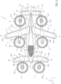
Figure 2 shows the aircraft ofFigure 1 in a top view; -
Figure 3 shows the aircraft ofFigure 1 in a front view; -
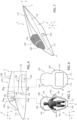
Figure 4 shows the fuselage of the aircraft ofFigure 1 in a side view, with parts removed for clarity's sake; -
Figures 5 and 6 are cross-sections along the lines V-V and VI-VI of the fuselage ofFigure 4 ; -
Figure 7 is a perspective view of the fuselage of the aircraft ofFigure 1 ; -
Figure 8 is a perspective view of the aircraft ofFigures 1 to 7 , with first components in transparency for clarity's sake; -
Figure 9 is a perspective view of the aircraft ofFigures 1 to 7 , with second components in transparency for clarity's sake; -
Figures 10 and 11 are front views of the fuselage of the aircraft ofFigures 1 to 9 , respectively with third and fourth components not shown for clarity's sake; -
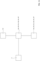
Figure 12 is a functional diagram of some components of the aircraft ofFigures 1 to 11 ; -
Figure 13 is a side view of a fuselage realized according to a second embodiment of the invention, with parts removed for clarity's sake; and -
Figure 14 is a cross-section of a fuselage realized according to a third embodiment of the invention, with parts removed for clarity's sake. - With reference to
Figures 1 to 11 , 1 denotes an aircraft capable of hovering. - In greater detail, the aircraft 1 is selectively switchable between:
- a first configuration (
Figures 1 ,2 and3 ), wherein it performs a hovering manoeuvre or moves forward along a predominantly vertical trajectory; and - a second configuration (
Figure 8 and9 ), wherein it is in a forward flight condition and proceeds along a mainly horizontal trajectory. - It must be specified that in the following present disclosure, expressions such as "above", "below", "at the front", "behind" and the like are used to refer to a normal forward or "hovering" flight condition of the convertiplane 1 shown in
Figures 1 ,2 ,3 ,8 and9 . - In a known manner, the rotations of the aircraft 1 around the axes Y, X, Z are associated with the following manoeuvres:
- roll, i.e. rotation around the axis Y;
- pitching, i.e. rotation around the axis X;
- yaw, i.e. rotation around the axis Z.
- More particularly, the aircraft 1 is intended for sports competitions or for use in a personal air mobility environment.
- The aircraft 1 essentially comprises:
- a
fuselage 2 which is elongated along the axis Y and defining anose 4 and atail 5 of the aircraft 1; - a pair of half-
wings 3 extending cantilevered from respective mutuallyopposite sidewalls 19 of thefuselage 2 and transversely to the axis Y; and - a
tail portion 6 projecting cantilevered from thetail 5 of thefuselage 2 transversely to thefuselage 2. - With reference to the normal forward flight operating condition, the aircraft 1 proceeds in a direction oriented from the
tail 5 to thenose 4 parallel to the axis Y. - The half-
wings 3 are intended to provide a first lift value to the aircraft 1 which is adapted to sustain the aircraft 1 arranged in the second configuration. - The half-
wings 3 comprise respectivefree ends 15 opposite thefuselage 2. - The half-
wings 3 extend above thefuselage 2. - The half-
wings 3 are divergent from each other proceeding from thefuselage 2 towards the respectivefree ends 15. - In the case shown, the half-
wings 3 comprise: -
respective root portions 11 projecting cantilevered fromrespective sidewalls 19; and -
respective end portions 12 arranged above thefuselage 2 and defining therespective ends 15 of the half-wings 3 themselves. - The
tail portion 6 comprises, in turn, anaerodynamic surface 8 adapted to generate a second lift/downforce value to ensure a desired degree of longitudinal stability to the aircraft 1 itself arranged in the second configuration. - In the case shown, the half-
wings 3 have negative deflection and/or negative dihedral angle. - The half-
wings 3 are, moreover, without movable aerodynamic surfaces, such as appendages or flaps, in the case shown. - Preferably, the aircraft 1 further comprises a pair of canard-type
aerodynamic surfaces 9 projecting cantilevered from respective mutually opposite sides of thenose 4 of thefuselage 2 and adapted to generate a third lift/downforce value to ensure the desired degree of longitudinal stability to the aircraft 1 itself arranged in the second configuration and to support the front propellers. - The
aerodynamic surfaces 9 comprise, in turn: -
respective root portions 17 projecting cantilevered from and connected torespective sidewalls 19 of thefuselage 2; and -
respective end portions 18 arranged on the opposite side of thecorresponding root portions 17 with respect to thefuselage 2. - In particular, the
root 17 and end 18 portions are inclined to each other (Figure 3 ). - In the case shown, the wingspan of the half-
wings 3 is greater than the wingspan of theaerodynamic surfaces 8. - The wingspan of the
aerodynamic surfaces 9 is greater than the wingspan of theaerodynamic surfaces 8. - In this description, the term "wingspan" means the distance between opposite free ends 15, of the respective half-
wings 3 and of theaerodynamic surfaces - The
aerodynamic surfaces 9 are arranged below the half-wings 3 (Figure 3 ). - The
fuselage 2 further comprises (Figures 4 to 7 ): - a pair of
portions nose 4 towards thetail 5; and - an electric power source 102 (only schematically shown in
Figures 4, 6 and8 ) arranged inside theportion 101 of thefuselage 2. - The
source 102 could comprise a plurality of electric batteries, a plurality of fuel cells, or an electric generator. - The
portion 100 defines ahousing 104 for afirst crew member 105. - The
portions second section 110, 111 (Figures 5, 6 and11 ) in a plane orthogonal to the axis Y. - Advantageously, the
portion 101 further comprises a pair ofair intakes 120 that are open towards the outside of thefuselage 2, oriented towards thenose 4, and fluidically connected with thesource 102 so as to convey, in use, a flow of cooling air onto thesource 102 itself, following the forward motion of aircraft 1; - the
section 111 has a larger area than thesection 110; - the air intakes 120 are arranged externally to said
portion 100 and on respective mutuallyopposite sidewalls 19 of theportion 100, in a view of the aircraft 1 according to a direction parallel to the axis Y. - The
fuselage 2 houses a conveying duct 109 (Figure 4 ) adapted to convey fresh cooling air onto thesource 102 and fluidically connected with theair intakes 120. - The
section 111 is symmetrical with respect to the axes Z, Y and comprises, in turn (Figure 6 ): - an
area 130; and - an
area 131 with greater extension than thearea 130, housing thesource 102 and defining saidair intakes 120. - The
area 131 is arranged below thearea 130 with respect to the axis Z, with reference to the normal forward position of the aircraft 1. - The
area 131 projects laterally from both sides of thearea 130, with reference to the axis X. - The
fuselage 2 further comprises atransparent dome 140 adapted to cover thehousing 104 for thefirst crew member 105. - The
dome 140 is carried by theportion 100. - The
dome 140 can slide or be opened laterally or towards thetail 5, in the case shown. - The
section 110 is also symmetrical with respect to the axes Y, Z and comprises, in turn (Figure 5 ): - an
area 145 arranged at thearea 130 along the axis Y; and - an
area 146 arranged at thearea 131 along the axis Y and arranged below thearea 145 with respect to the axis Z, with reference to the normal forward position of the aircraft 1. - The
area 145 is contained in thearea 130 and thearea 146 is contained in thearea 131, in a view of the aircraft 1 parallel to the axis Y. - The
section 110 further comprises anarea 150 interposed between theareas - The
area 145 is shaped to accommodate the head of thefirst crew member 105 and thearea 146 is shaped to support the legs of the aforesaidfirst crew member 105. - The
area 150 projects from both sides of theareas lateral fairings 142 adapted to accommodate respective arms of thefirst crew member 105. - In this way, the
section 100 defines a safety cell for thefirst crew member 105. - The aircraft 1 further comprises (
Figures 1 ): - a
portion 107 interposed between thenose 4 and theportion 100 along the axis Y; and - a
portion 108 interposed between theportion 101 and thetail 5 along the axis Y. - The half-
wings 3 are fixed to theportion 108. - The
portions respective stretches - The
stretch 112 extends between thedome 140 and thenose 4 along the axis Y. Thestretch 112 is inclined with respect to the axis Y and extends below thedome 140 at progressively increasing distances from thedome 140 proceeding towards thenose 4 and measured along the axis Z. - The
stretch 113 extends between theportion 101 and thetail 5 along the axis Y. Thestretch 113 is inclined with respect to the axis Y and extends below theportion 101 at progressively increasing distances from thedome 140 proceeding towards thetail 5 and measured along the axis Z. - The
portions - The
aerodynamic surfaces 9 comprise respective foam inserts 201, 202 carried respectively by the correspondingroot 17 and end 18 portions (Figure 2 ). - The half-
wings 3 comprise respective foam inserts 203, 204 carried respectively by the correspondingroot 11 and end 12 portions. - The
aerodynamic surface 8 comprises a cup of foam inserts 205 arranged symmetrically with respect to the axis Y. - The
inserts aerodynamic surfaces 9, to the half-wings 3 and to theaerodynamic surfaces 8, and confer buoyancy capacity to the aircraft 1. - The aircraft 1 further comprises (
Figures 1 to 3 ): - a pair of
rotors fuselage 2; - a pair of
rotors fuselage 2; and - a pair of
rotors Figure 2 ) between a first position that is assumed when the aircraft 1 is in the first configuration (Figures 1 to 3 ) and a second position that is assumed when the aircraft 1 is in the second configuration (Figures 8 and9 ). - In the shown case, the axes F, G of the
rotors nose 4 or thetail 5 with respect to the axis Z. - The aircraft 1 further comprises:
- a plurality of
electric powertrains Figure 12 ) adapted to be electrically powered wholly or partly by thesource 102 and to drag into rotationrespective rotors - a control unit 71 (only schematically shown in
Figure 12 ) receiving as input a plurality of control signals provided by the crew or by an autopilot or a remote control system, and programmed to provide as output a plurality of commands to command theelectric powertrains respective rotors - In greater detail, the
control unit 71 is programmed to command therotors - More particularly, the
control unit 71 is programmed to command therotors - The
control unit 71 is programmed to command therotors - The axes B, C; D, E and F, G are arranged symmetrically to the axis Y.
- In the case shown, the axes B, C, D and E are parallel to each other and parallel to the axis Z.
- The axes B, D, F; C, E, G are aligned with each other orthogonally to the axis Y when the aircraft 1 is arranged in the first configuration.
- The axes F, G are arranged parallel to the axis Z when the
rotors - The axes F, G are arranged orthogonally to the axes B, C; D, E and parallel to the axis Y when the
rotors - In one embodiment, the
rotors - The aircraft 1 further comprises (
Figures 2 ): - a pair of
supports respective rotors aerodynamic surfaces 9; - a pair of
supports respective rotors wings 3 and to thetail portion 6; and - a pair of
supports respective rotors wings 3 in an inclinable manner with respect to the axis H. - Preferably, the
supports ends 15 of the respective half-wings 3, with reference to an extension direction of the same half-wings 3. - The
supports aerodynamic surfaces 9, with reference to an extension direction of the sameaerodynamic surfaces 9. - In particular, the
supports aerodynamic surfaces 9 in front of thenose 4 and lying on respective planes orthogonal to the direction Y and arranged vertically in the normal position of the aircraft 1 (Figure 1 ). - The axes B, C are arranged in front of the
nose 4. - The axes D, E are arranged in front of the respective
aerodynamic surfaces 8. - The
rotors wings 3 and thenose 4 along the axis Y both when the aircraft 1 is arranged in the first configuration and when the aircraft 1 is arranged in the second configuration. - The
rotors wings 3 when the aircraft 1 is arranged in the first configuration (Figures 1 ,2 and3 ), and in front of the respective half-wings 3 when the aircraft 1 is arranged in the second configuration (Figures 8 and9 ) . - With particular reference to
Figure 9 , thetail portion 6 essentially comprises: - the
aerodynamic surface 8 extending from respective mutually opposite sides of thetail 5 and lying on a plane substantially orthogonal to the axis Z; and - a pair of
drifts 52 projecting cantilevered from mutually opposite ends 53 of thesurface 8. - In greater detail, each
rotor 52 essentially comprises: - a
portion 54 extending upwards starting from therelative end 53 with reference to the normal position of the aircraft 1 and lying on a plane inclined with respect to the axes Y, Z; and - a
portion 55 extending downwards starting from therelative end 53 with reference to the normal position of the aircraft 1, inclined with respect to theportion 54, and lying on a plane orthogonal to the axis X. - The
supports wing 3 and theportion 55 of arespective drift 52. - The
portions rotors - In particular, the
surface 8 comprises (Figure 8 ): - a
main portion 60; and - an appendage 61 (visible only in
Figure 8 ) movably connected to themain portion 60. - In the shown case, the
appendage 61 is arranged behind themain portion 60 with reference to the normal forward position of the aircraft 1, and is hinged to themain portion 60 around an axis parallel to the axes H, X. - The aircraft 1 further comprises an
actuator 65 operable to rotate theappendage 61 with respect to themain portion 60 and around the axis parallel to the axes H, X. - The
actuator 65 essentially comprises (Figure 8 ): - a
fixed body 66 housed in thefuselage 2 and housing aservomotor 64; - a
rod 67 elongated parallel to the axes H, X and fixed to theappendage 61; and - a rod 68 slidable with respect to the fixed
body 66 parallel to the direction Y following actuation of theservomotor 64 and hinged, on the opposite side of the fixedbody 66, to therod 67 around the axis parallel to the axes H, X. - The aircraft 1 further comprises (
Figures 1 and8 ): - a pair of
carriages 45 carried by respectiveaerodynamic surfaces 9; and - a pair of
carriages 46 carried byrespective portions 55 from thedrift 52 on the side opposite thesurface 8. - The
carriages aerodynamic surfaces 9 and to theportions 55, respectively. - The following describes the operation of the aircraft 1, with reference to a use in a sports competition and/or in a personal/urban air vehicle (PAV) environment.
- The
first crew member 105 accesses theportion 100 through the sliding or laterallyopenable dome 140. - Next, the
first crew member 105 is accommodated in theportion 100 of thefuselage 2. - The
source 102 powers, in whole or in part thepowertrains - The air intakes 120 convey fresh air into the
duct 109, which continuously cools thesource 102. - The
control unit 71 receives as input a plurality of control signals provided by the crew, by an autopilot or a remote control system, provides as output a plurality of commands to command theelectric powertrains respective rotors - The aircraft 1 lands and takes off arranged in the first configuration with the
rotors Figures 1 ,2 and3 ). - The aircraft 1 moves forward cruising in the second configuration with the
rotors Figures 8 and9 ). - In the first configuration, the lift required to sustain the aircraft 1 is provided by the
rotors - In the second configuration, the lift required to sustain the aircraft 1 is mostly provided by the half-
wings 3. Therotors - The control and the manoeuvrability of the aircraft around the axes X, Y, Z is obtained by appropriately acting on the values of the thrusts generated by the
rotors rotors - With reference to the second configuration, the variation of the angle of inclination of the
appendage 61 through theactuator 65 contributes to controlling and manoeuvring the aircraft 1 with respect to the axis X. - With reference to
Figure 13 , 2' denotes a fuselage according to a second embodiment of the present invention. - The fuselage 2' is similar to the
fuselage 2 and will be described below only in so far as it differs from the latter; equal or equivalent parts of thefuselages 2, 2' will be marked, where possible, with the same reference numbers. - In particular, the fuselage 2' differs from the
fuselage 2 in that theportion 101 defines a housing 104' for asecond crew member 106 arranged behind thehousing 104 along the axis Y. In particular, the housing 104' allows thesecond member 106 to sit astride at least a front portion of thesource 102. - The dome 140' also extends beyond the
portion 101 towards thetail 5 so as to be arranged above the housing 104'. - The operation of the fuselage 2' is completely similar to that of the
fuselage 2 and is therefore not described in detail. - With reference to
Figure 14 ,2 " denotes a fuselage according to a third embodiment of the present invention. - The
fuselage 2" is similar to thefuselage 2 and will be described below only in so far as it differs from the latter; equal or equivalent parts of thefuselages 2, 2'' will be marked, where possible, with the same reference numbers. - In particular, the fuselage 2'' differs from the
fuselage 2 in that theportion 101 defines ahousing 104" for a second and athird crew member 106a", 106b" side by side along the axis X. - The
section 111" is conformed similarly to thesection 111 of thefuselage 2 but has increased overall dimensions in order to accommodate the two crew members. - In a nutshell, the
section 111" comprises: - an
area 145"; and - an
area 146" arranged below thearea 146", with reference to the normal forward position of the aircraft 1; and - an
area 150" interposed between theareas - The
area 145" is shaped to accommodate the heads of the first andsecond crew members 106a", 106b" and thearea 146" is shaped to support the legs of the aforesaid first andsecond crew member - The
area 150" projects from both sides of theareas 145", 146", with reference to the axis X, so as to define twolateral fairings 142" adapted to accommodate the arms of thefirst member 105 and of thesecond member 106 of the crew. - The operation of the
fuselage 2" is completely similar to that of thefuselage 2 and is therefore not described in detail. - From an examination of the characteristics of the
fuselage - In greater detail, the
section 111 of theportion 101 has a larger area than thesection 110 and defines the air intakes 120 intended to convey the cooling air towards thesource 102. - In other words, the
fuselage 2, 2' 2'' comprises theportion 100 defining thehousing 104 for thefirst crew member 105, and theportion 101 defining the air intakes 120 and housing thesource 102. - It is thus possible to use the
same fuselage first member 105 and to cool thesource 102. - The
sections fuselage - The position and/or shaping of the air intakes 120 that are lateral to the
section 111 contributes to decreasing the aerodynamic drag of thefuselage - This makes it possible to realize a
fuselage 2, 2', 2'' particularly suitable for the aircraft 1 intended for sports competitions or for use in an urban air mobility scenario. - The
section 110 of theportion 100 defines a safety cell for thefirst crew member 105 formed by: - the
area 145 shaped to accommodate the head of thefirst crew member 105; - the
area 146 shaped to support the legs of the aforesaidfirst crew member 105; and - the
area 150 projecting from both sides of theareas lateral fairings 142 adapted to accommodate respective arms of thefirst crew member 105. - Similarly, the
section 111" of the fuselage 2'' defines a safety cell for the second andthird crew member 106a", 106b". - The
sections dome 140, 140', measured parallel to the axis Z and proceeding towards thenose 4 and thetail 5 of thefuselage - This arrangement combined with the conformation of the
sections housing housing - The
fuselage 2, 2', 2'' supports and connects the half-wings 3 and theaerodynamic surfaces housing - The
fuselage body 66 of theactuator 65 adapted to control the position of theappendage 61 with respect to themain portion 60 of the tail plane 50, thereby greatly reducing the aerodynamic drag of the aircraft 1 with respect to the solutions of the known type. - Preferably, the half-
wings 3 have negative deflection and/or negative dihedral angle. - Thus, the half-
wings 3 are optimized for forward flight in the first high-speed configuration and ensure high stability to the aircraft 1 in the aforesaid first configuration. - The half-
wings 3 have no movable ailerons, thus resulting in a particularly simple shape and geometry. - The foam inserts 201, 202; 203, 204; and 205 arranged in the
aerodynamic surfaces 9, in the half-wings 3, and in theaerodynamic surface 8 confer structural strength buoyancy capacity to the aircraft 1. - The density of such foam inserts 201, 202; 203, 204; 205 is determined based on the construction needs and the performance requirements of the aircraft 1.
- This makes aircraft 1 particularly suitable for competition scenarios or for use in sufficiently large portions of the sea, lakes or rivers.
- It is clear that the
fuselage - In particular, the
fuselage 2, 2', 2'' could comprise asingle air intake 120 arranged at arelative sidewall 19. - The
housing 104 could accommodate twofirst crew members 105 arranged side by side parallel to the axis X. - The aircraft 1 could comprise instead of the
rotors fuselage 2, and configured to generate a thrust parallel to the axis Y under forward flight conditions. - The aircraft 1 may not comprise the
aerodynamic surfaces 8. - The axes B, C; D, E may not be parallel to the axis Z and may be inclined with respect to the axis Z by an angle ranging between - 15 and + 15 degrees. In particular, the axes B, C (D, E) could converge in the axis Z above or below the
fuselage 2. - Some or all of the
rotors - The
carriages - Finally, the aircraft 1 may not comprise the
aerodynamic surface 8. In this case, thetail portion 6 would comprise a pair of drifts projecting cantilevered downwards from thetail 5 and diverging symmetrically to the axis Y starting from thetail 5 downwards.
Claims (15)
- - Fuselage (2, 2', 2") for a convertible aircraft (1), comprising:- a nose (4) and a tail (5) arranged at mutually opposite sides along a first longitudinal axis (Y) of said fuselage (2, 2', 2");- a first portion (100) and a second portion (101) arranged one after the other, proceeding along said first axis (Y) from said nose (4) towards said tail (5); and- an electric power source (102) connectable with at least one electric powertrain (40a, 40b, 40c, 40d, 40e, 40f) of said aircraft (1) and arranged inside said second portion (101);said first and second portion (100, 101) defining a first and second section (110, 111, 111") respectively in a plane orthogonal to said first axis (Y);characterized in that said second section (111) defines at least one air intake (120) that is open towards the outside of the fuselage (2) itself and fluidically connected with said source (102) so as to convey, in use, a flow of cooling air onto the source (102) itself following the forward motion of said aircraft (1);said second section (111, 111") having a larger area than said first section (110);said air intake (120) being arranged at one sidewall (19) of said second portion (101);said air intake (120) being arranged externally to said first portion (100) and in a view of said fuselage (2, 2', 2") parallel to said first axis (Y).
- - Fuselage according to claim 1, characterized in that said first section (110) comprises, in turn:- a first area (145); and- a second area (146) arranged below said first area (145), with reference to said normal forward motion position of said fuselage (2, 2', 2").
- - Fuselage according to claim 2, characterized in that said first section (110) defines a first housing (104) for a first crew member (105);said first section (110) comprising a third area (150) interposed between said first and second area (145, 146) along a second axis (Z) orthogonal to said first axis (Y);said third area (150) projecting from both sides of said first and second area (145, 146), with reference to a third axis (X) orthogonal to said first axis (Y) and to said second axis (Z), so as to define two lateral fairings (142) adapted to accommodate respective arms of said first member (105) of said crew.
- - Fuselage according to claim 2 or 3, characterized in that said second section (111, 111") comprises, in turn:- a fourth area (130) arranged at said first area (145) along said first axis (Y); and- a fifth area (131) with greater extension than said fourth area (130), arranged at said second area (146), and housing said source (102) and defining said air intake (120);said fifth area (131) being arranged below said fourth area (130), with reference to a normal position of said aircraft (1);said fifth area (131) projecting laterally from both sides of said fourth area (130).
- - Fuselage according to claim 3 or 4, characterized in that said second portion (101) defines a second housing (104') for a second member (106) of the crew or a third housing (104") for a second and third member (106a", 106b") of said crew that are arranged side by side, in use, along said third axis (X);
said second section (111) defining a pair of lateral fairings (142") interposed along said second axis (Z) between said fourth and fifth area (145, 146), and projecting laterally from said fourth and fifth area (145, 146) parallel to said third axis (X). - - Fuselage according to any one of the preceding claims, characterized in that said first and second portion (100, 101) are joined together; and/or
characterized in that it comprises:- a transparent dome (140, 140') extending partially within at least one of said first and second portion (100, 101) ;- a first stretch (112) extending from said dome (140, 140') towards said nose (4) at progressively increasing distances from the dome (140, 140') itself measured along said second axis (Z); and- a second stretch (113) extending from said dome (140) towards said tail (5) at progressively increasing distances from the dome (140, 140') itself measured along said second axis (Z). - - Convertible aircraft (1) comprising:- a fuselage (2, 2', 2") according to any one of the preceding claims; and- a pair of half-wings (3) arranged on respective mutually opposite lateral sides of said fuselage (2, 2', 2') and generating, in use, a first lift value;- a first and a second rotor (22a, 22b) carried by respective said half-wings (3), respectively rotatable around a fourth and fifth axis (F, G) inclinable with respect to said fuselage (2, 2', 2"), and operable independently of each other;said fourth and fifth axis (F, G) being arranged on respective mutually opposite lateral sides of said fuselage (2, 2', 2") and symmetrically with respect to said first axis (Y);said aircraft (1) being switchable between:- a first hovering or take-off/landing flight configuration wherein said fourth and fifth axis (F, G) are arranged orthogonal to said first axis (Y); and- a second forward flight configuration wherein said fourth and fifth axis (F, G) are arranged parallel to or inclined with respect to said first axis (Y).
- - Aircraft according to claim 7, characterized in that said half-wings (3) are fixed to a third portion (108) of said fuselage (2, 2', 2");
said third portion (108) being interposed between said second portion (101) and said tail (5) along said first axis (Y). - - Aircraft according to claim 7 or 8, characterized in that said half-wings (3) have negative deflection and/or negative dihedral angle; and/or
characterized in that said half-wings (3) have no respective aerodynamic surfaces movable with respect to said half-wings (3) themselves. - - Aircraft according to any one of claims 7 to 9, characterized in that it comprises:- a tail portion (6) extending from both sides of said tail (6); and- an actuator (65) operable to move said appendage (61) ;said tail portion (6) comprises, in turn:- a second aerodynamic surface (8) adapted to provide a second lift/downforce value and projecting cantilevered from respective mutually opposite lateral sides of said tail (5) of said fuselage (2); and- an appendage (61) movable with respect to said second aerodynamic surface (8);said actuator (65) comprising, in turn:- a fixed body (66) housed inside said fuselage (2); and- a rod (67) operatively connected to said fixed body (66) and to said appendage (61).
- - Aircraft according to any one of claims 8 to 10, characterized in that it comprises a pair of third aerodynamic surfaces (9) adapted to provide third lift/downforce values and projecting cantilevered from respective mutually opposite lateral sides of said nose (4) of said fuselage (2).
- - Aircraft according to any one of claims 8 to 11, characterized in that it comprises:- a third and fourth rotor (21a, 21b) respectively rotatable around a sixth and a seventh axis (D, E) that are fixed with respect to said fuselage (2); and- a fifth and sixth rotor (20a, 20b) respectively rotatable around an eighth and ninth axis (B, C) that are fixed with respect to said fuselage (2, 2', 2").
- - Aircraft according to claim 12, characterized in that said fourth and fifth axis (F, G), sixth and seventh axis (D, E), eighth and ninth axis (B, C) are arranged symmetrically with respect to said first axis (Y); and/or
characterized in that said fourth, sixth and eighth axis (F, D, B) and said fifth, seventh and ninth axis (G, E, C) are aligned parallel to said first axis (Y) when said aircraft is in said first configuration. - - Aircraft according to any one of claims 8 to 13, characterized in that it comprises at least one electric powertrain (40a, 40b, 40c, 40d, 40e, 40f) operatively connected with said source (102) and with at least one of said first, second, third, fourth, fifth and sixth rotor (20a, 20b, 21a, 21b, 22a, 22b);
at least one pair of said first, second, third, fourth, fifth and sixth rotor (20a, 20b, 21a, 21b, 22a, 22b) being operable independently of each other. - - Aircraft according to any one of claims 11 to 14, characterized in that at least one of said half-wings (3), second aerodynamic surface (8) and third aerodynamic surfaces (9) comprises a foam insert at respective end zones of the fuselage (2).
Priority Applications (5)
| Application Number | Priority Date | Filing Date | Title |
|---|---|---|---|
| EP22174037.6A EP4279390B1 (en) | 2022-05-18 | 2022-05-18 | Fuselage for a vertical take-off and landing aircraft |
| CN202380041229.7A CN119233930A (en) | 2022-05-18 | 2023-04-21 | Fuselage for a convertible aircraft capable of hovering |
| PCT/IB2023/054080 WO2023223119A1 (en) | 2022-05-18 | 2023-04-21 | Fuselage for a convertible aircraft capable of hovering |
| KR1020247041941A KR20250033154A (en) | 2022-05-18 | 2023-04-21 | Fuselage for a convertible aircraft capable of hovering |
| US18/865,800 US12503245B2 (en) | 2022-05-18 | 2023-04-21 | Fuselage for a convertible aircraft capable of hovering |
Applications Claiming Priority (1)
| Application Number | Priority Date | Filing Date | Title |
|---|---|---|---|
| EP22174037.6A EP4279390B1 (en) | 2022-05-18 | 2022-05-18 | Fuselage for a vertical take-off and landing aircraft |
Publications (2)
| Publication Number | Publication Date |
|---|---|
| EP4279390A1 true EP4279390A1 (en) | 2023-11-22 |
| EP4279390B1 EP4279390B1 (en) | 2024-07-03 |
Family
ID=82446423
Family Applications (1)
| Application Number | Title | Priority Date | Filing Date |
|---|---|---|---|
| EP22174037.6A Active EP4279390B1 (en) | 2022-05-18 | 2022-05-18 | Fuselage for a vertical take-off and landing aircraft |
Country Status (5)
| Country | Link |
|---|---|
| US (1) | US12503245B2 (en) |
| EP (1) | EP4279390B1 (en) |
| KR (1) | KR20250033154A (en) |
| CN (1) | CN119233930A (en) |
| WO (1) | WO2023223119A1 (en) |
Cited By (4)
| Publication number | Priority date | Publication date | Assignee | Title |
|---|---|---|---|---|
| US20250083809A1 (en) * | 2022-01-11 | 2025-03-13 | Glen Newman | Evtol aircraft |
| WO2025219682A1 (en) * | 2024-04-19 | 2025-10-23 | Ascendance Flight Technologies | Control system for cooling on-board equipment of a vertical take-off and landing aircraft |
| EP4653316A1 (en) | 2024-05-24 | 2025-11-26 | Leonardo S.p.a. | Convertible aircraft capable of hovering |
| EP4653315A1 (en) | 2024-05-24 | 2025-11-26 | Leonardo S.p.a. | Convertible aircraft capable of hovering |
Citations (11)
| Publication number | Priority date | Publication date | Assignee | Title |
|---|---|---|---|---|
| DE19647594A1 (en) * | 1996-11-18 | 1997-04-30 | Karl Dipl Ing Bauer | Streamlined cover for para glider pilots |
| EP2604519A1 (en) * | 2011-10-17 | 2013-06-19 | Yu Tian | Composite aircraft consisting of fixed-wing and electrically driven propellers |
| KR20150020892A (en) * | 2013-08-19 | 2015-02-27 | 한국항공우주연구원 | Wind pressure interconnected variable vane system for engine clooing of tilt-rotor-aircraft |
| US10011349B2 (en) | 2016-08-31 | 2018-07-03 | Bell Helicopter Textron Inc. | Tiltrotor aircraft having rotatable wing extensions |
| US20190127056A1 (en) * | 2017-10-27 | 2019-05-02 | Elroy Air, Inc. | Compound multi-copter aircraft |
| US10577075B1 (en) * | 2017-05-03 | 2020-03-03 | Northrop Grumman Systems Corporation | Interlocking device for aircraft cockpit frames |
| WO2020105045A1 (en) | 2018-11-25 | 2020-05-28 | Israel Aerospace Industries Ltd. | Air vehicle and method of operation of air vehicle |
| US20200398968A1 (en) * | 2019-06-20 | 2020-12-24 | Tsc, Llc | Integrated Pultruded Composite Profiles and Method for Making Same |
| US20210094374A1 (en) * | 2019-09-30 | 2021-04-01 | Subaru Corporation | Land-and-air vehicle and method of operating land-and-air vehicle |
| WO2021112954A2 (en) * | 2019-10-09 | 2021-06-10 | Kitty Hawk Corporation | Tilting mechanism with telescoping actuator |
| US20210284333A1 (en) * | 2020-03-16 | 2021-09-16 | Anthony Windisch | Small light vertical take-off and landing capable delta wing aircraft |
Family Cites Families (16)
| Publication number | Priority date | Publication date | Assignee | Title |
|---|---|---|---|---|
| US6488232B2 (en) | 1998-12-16 | 2002-12-03 | Trek Aerospace, Inc. | Single passenger aircraft |
| US20020113165A1 (en) | 2000-12-13 | 2002-08-22 | Michael Moshier | Aircraft and control system |
| US6464166B1 (en) | 2001-05-29 | 2002-10-15 | Romeo Yankee Ltd. | Ducted fan vehicles particularly useful as VTOL aircraft |
| US20030062442A1 (en) * | 2001-10-02 | 2003-04-03 | Milde Karl F. | VTOL personal aircraft |
| JP2003137192A (en) | 2001-10-31 | 2003-05-14 | Mitsubishi Heavy Ind Ltd | Vertical taking-off/landing craft |
| US20040094662A1 (en) | 2002-01-07 | 2004-05-20 | Sanders John K. | Vertical tale-off landing hovercraft |
| US7461811B2 (en) | 2002-09-11 | 2008-12-09 | Milde Jr Karl F | VTOL personal aircraft |
| US6892979B2 (en) | 2002-09-11 | 2005-05-17 | Karl F. Milde, Jr. | VTOL personal aircraft |
| US7472863B2 (en) | 2004-07-09 | 2009-01-06 | Steve Pak | Sky hopper |
| US20060226281A1 (en) | 2004-11-17 | 2006-10-12 | Walton Joh-Paul C | Ducted fan vertical take-off and landing vehicle |
| US7857254B2 (en) | 2004-12-22 | 2010-12-28 | Aurora Flight Sciences Corporation | System and method for utilizing stored electrical energy for VTOL aircraft thrust enhancement and attitude control |
| US7267300B2 (en) | 2005-02-25 | 2007-09-11 | The Boeing Company | Aircraft capable of vertical and short take-off and landing |
| US8152096B2 (en) * | 2005-10-18 | 2012-04-10 | Smith Frick A | Apparatus and method for vertical take-off and landing aircraft |
| US20080054121A1 (en) | 2006-05-11 | 2008-03-06 | Urban Aeronautics Ltd. | Ducted fan VTOL vehicles |
| IL199009A (en) | 2009-05-27 | 2013-11-28 | Israel Aerospace Ind Ltd | Air vehicle |
| US10577091B2 (en) * | 2017-04-24 | 2020-03-03 | Bcg Digital Ventures Gmbh | Vertical take-off and landing aircraft |
-
2022
- 2022-05-18 EP EP22174037.6A patent/EP4279390B1/en active Active
-
2023
- 2023-04-21 KR KR1020247041941A patent/KR20250033154A/en active Pending
- 2023-04-21 US US18/865,800 patent/US12503245B2/en active Active
- 2023-04-21 CN CN202380041229.7A patent/CN119233930A/en active Pending
- 2023-04-21 WO PCT/IB2023/054080 patent/WO2023223119A1/en not_active Ceased
Patent Citations (11)
| Publication number | Priority date | Publication date | Assignee | Title |
|---|---|---|---|---|
| DE19647594A1 (en) * | 1996-11-18 | 1997-04-30 | Karl Dipl Ing Bauer | Streamlined cover for para glider pilots |
| EP2604519A1 (en) * | 2011-10-17 | 2013-06-19 | Yu Tian | Composite aircraft consisting of fixed-wing and electrically driven propellers |
| KR20150020892A (en) * | 2013-08-19 | 2015-02-27 | 한국항공우주연구원 | Wind pressure interconnected variable vane system for engine clooing of tilt-rotor-aircraft |
| US10011349B2 (en) | 2016-08-31 | 2018-07-03 | Bell Helicopter Textron Inc. | Tiltrotor aircraft having rotatable wing extensions |
| US10577075B1 (en) * | 2017-05-03 | 2020-03-03 | Northrop Grumman Systems Corporation | Interlocking device for aircraft cockpit frames |
| US20190127056A1 (en) * | 2017-10-27 | 2019-05-02 | Elroy Air, Inc. | Compound multi-copter aircraft |
| WO2020105045A1 (en) | 2018-11-25 | 2020-05-28 | Israel Aerospace Industries Ltd. | Air vehicle and method of operation of air vehicle |
| US20200398968A1 (en) * | 2019-06-20 | 2020-12-24 | Tsc, Llc | Integrated Pultruded Composite Profiles and Method for Making Same |
| US20210094374A1 (en) * | 2019-09-30 | 2021-04-01 | Subaru Corporation | Land-and-air vehicle and method of operating land-and-air vehicle |
| WO2021112954A2 (en) * | 2019-10-09 | 2021-06-10 | Kitty Hawk Corporation | Tilting mechanism with telescoping actuator |
| US20210284333A1 (en) * | 2020-03-16 | 2021-09-16 | Anthony Windisch | Small light vertical take-off and landing capable delta wing aircraft |
Cited By (8)
| Publication number | Priority date | Publication date | Assignee | Title |
|---|---|---|---|---|
| US20250083809A1 (en) * | 2022-01-11 | 2025-03-13 | Glen Newman | Evtol aircraft |
| US12612159B2 (en) * | 2022-01-11 | 2026-04-28 | Glen Newman | EVTOL aircraft |
| WO2025219682A1 (en) * | 2024-04-19 | 2025-10-23 | Ascendance Flight Technologies | Control system for cooling on-board equipment of a vertical take-off and landing aircraft |
| FR3161416A1 (en) * | 2024-04-19 | 2025-10-24 | Ascendance Flight Technologies | Control system for cooling on-board equipment of a vertical takeoff and landing aircraft |
| EP4653316A1 (en) | 2024-05-24 | 2025-11-26 | Leonardo S.p.a. | Convertible aircraft capable of hovering |
| EP4653315A1 (en) | 2024-05-24 | 2025-11-26 | Leonardo S.p.a. | Convertible aircraft capable of hovering |
| WO2025243115A1 (en) | 2024-05-24 | 2025-11-27 | Leonardo S.P.A. | Convertible aircraft capable of hovering |
| WO2025243114A1 (en) | 2024-05-24 | 2025-11-27 | Leonardo S.P.A. | Convertible aircraft capable of hovering |
Also Published As
| Publication number | Publication date |
|---|---|
| EP4279390B1 (en) | 2024-07-03 |
| US20250313336A1 (en) | 2025-10-09 |
| WO2023223119A1 (en) | 2023-11-23 |
| KR20250033154A (en) | 2025-03-07 |
| US12503245B2 (en) | 2025-12-23 |
| CN119233930A (en) | 2024-12-31 |
Similar Documents
| Publication | Publication Date | Title |
|---|---|---|
| EP3704019B1 (en) | VERTICALLY TAKE-OFF AND LANDING (VTOL) AIRCRAFT WITH FIXED-WING AND ROTARY-WING CONFIGURATIONS | |
| US11873086B2 (en) | Variable-sweep wing aerial vehicle with VTOL capabilites | |
| KR20220074826A (en) | New Aircraft Design Using Tandem Wings and Distributed Propulsion System | |
| US12503245B2 (en) | Fuselage for a convertible aircraft capable of hovering | |
| RU2661277C1 (en) | Unmanned carrier-based convertible rotorcraft | |
| CN111498109A (en) | Vertical take-off and landing aircraft | |
| US12486055B2 (en) | Series of convertible aircrafts capable of hovering and method for configuring a convertible aircraft capable of hovering | |
| EP3860912B1 (en) | Vertical and short takeoff and landing (vstol) aircraft | |
| WO2015200345A1 (en) | Five-wing aircraft to permit smooth transitions between vertical and horizontal flight | |
| US20240300644A1 (en) | Vertical take-off box wing aircraft | |
| US12404046B2 (en) | Series of convertible aircraft capable of hovering and method for configuring a convertible aircraft capable of hovering | |
| RU2674622C1 (en) | Convertiplane | |
| US12358617B2 (en) | Convertible aircraft capable of hovering | |
| CN116635298A (en) | Vertical take-off and landing aircraft with fuselage and wings integrated into aerodynamic airfoils | |
| US12552529B2 (en) | Convertible aircraft capable of hovering | |
| RU208853U1 (en) | VTOL unmanned aerial vehicle designed for aerial surveying | |
| RU222496U1 (en) | Vertical take-off and landing unmanned aerial vehicle | |
| EP4653316A1 (en) | Convertible aircraft capable of hovering |
Legal Events
| Date | Code | Title | Description |
|---|---|---|---|
| STAA | Information on the status of an ep patent application or granted ep patent |
Free format text: STATUS: EXAMINATION IS IN PROGRESS |
|
| PUAI | Public reference made under article 153(3) epc to a published international application that has entered the european phase |
Free format text: ORIGINAL CODE: 0009012 |
|
| 17P | Request for examination filed |
Effective date: 20221216 |
|
| AK | Designated contracting states |
Kind code of ref document: A1 Designated state(s): AL AT BE BG CH CY CZ DE DK EE ES FI FR GB GR HR HU IE IS IT LI LT LU LV MC MK MT NL NO PL PT RO RS SE SI SK SM TR |
|
| RIC1 | Information provided on ipc code assigned before grant |
Ipc: B64U 101/61 20230101ALI20231220BHEP Ipc: B64C 1/00 20060101ALI20231220BHEP Ipc: B64C 1/14 20060101ALI20231220BHEP Ipc: B64C 7/00 20060101ALI20231220BHEP Ipc: B64C 29/00 20060101ALI20231220BHEP Ipc: B64D 33/08 20060101ALI20231220BHEP Ipc: B64D 27/24 20060101AFI20231220BHEP |
|
| GRAP | Despatch of communication of intention to grant a patent |
Free format text: ORIGINAL CODE: EPIDOSNIGR1 |
|
| STAA | Information on the status of an ep patent application or granted ep patent |
Free format text: STATUS: GRANT OF PATENT IS INTENDED |
|
| INTG | Intention to grant announced |
Effective date: 20240201 |
|
| GRAS | Grant fee paid |
Free format text: ORIGINAL CODE: EPIDOSNIGR3 |
|
| GRAA | (expected) grant |
Free format text: ORIGINAL CODE: 0009210 |
|
| STAA | Information on the status of an ep patent application or granted ep patent |
Free format text: STATUS: THE PATENT HAS BEEN GRANTED |
|
| P01 | Opt-out of the competence of the unified patent court (upc) registered |
Effective date: 20240508 |
|
| AK | Designated contracting states |
Kind code of ref document: B1 Designated state(s): AL AT BE BG CH CY CZ DE DK EE ES FI FR GB GR HR HU IE IS IT LI LT LU LV MC MK MT NL NO PL PT RO RS SE SI SK SM TR |
|
| REG | Reference to a national code |
Ref country code: CH Ref legal event code: EP |
|
| REG | Reference to a national code |
Ref country code: DE Ref legal event code: R096 Ref document number: 602022004256 Country of ref document: DE |
|
| REG | Reference to a national code |
Ref country code: LT Ref legal event code: MG9D |
|
| REG | Reference to a national code |
Ref country code: NL Ref legal event code: MP Effective date: 20240703 |
|
| PG25 | Lapsed in a contracting state [announced via postgrant information from national office to epo] |
Ref country code: PT Free format text: LAPSE BECAUSE OF FAILURE TO SUBMIT A TRANSLATION OF THE DESCRIPTION OR TO PAY THE FEE WITHIN THE PRESCRIBED TIME-LIMIT Effective date: 20241104 |
|
| REG | Reference to a national code |
Ref country code: AT Ref legal event code: MK05 Ref document number: 1699585 Country of ref document: AT Kind code of ref document: T Effective date: 20240703 |
|
| PG25 | Lapsed in a contracting state [announced via postgrant information from national office to epo] |
Ref country code: NL Free format text: LAPSE BECAUSE OF FAILURE TO SUBMIT A TRANSLATION OF THE DESCRIPTION OR TO PAY THE FEE WITHIN THE PRESCRIBED TIME-LIMIT Effective date: 20240703 |
|
| PG25 | Lapsed in a contracting state [announced via postgrant information from national office to epo] |
Ref country code: PT Free format text: LAPSE BECAUSE OF FAILURE TO SUBMIT A TRANSLATION OF THE DESCRIPTION OR TO PAY THE FEE WITHIN THE PRESCRIBED TIME-LIMIT Effective date: 20241104 Ref country code: NL Free format text: LAPSE BECAUSE OF FAILURE TO SUBMIT A TRANSLATION OF THE DESCRIPTION OR TO PAY THE FEE WITHIN THE PRESCRIBED TIME-LIMIT Effective date: 20240703 |
|
| PG25 | Lapsed in a contracting state [announced via postgrant information from national office to epo] |
Ref country code: NO Free format text: LAPSE BECAUSE OF FAILURE TO SUBMIT A TRANSLATION OF THE DESCRIPTION OR TO PAY THE FEE WITHIN THE PRESCRIBED TIME-LIMIT Effective date: 20241003 |
|
| PG25 | Lapsed in a contracting state [announced via postgrant information from national office to epo] |
Ref country code: FI Free format text: LAPSE BECAUSE OF FAILURE TO SUBMIT A TRANSLATION OF THE DESCRIPTION OR TO PAY THE FEE WITHIN THE PRESCRIBED TIME-LIMIT Effective date: 20240703 Ref country code: PL Free format text: LAPSE BECAUSE OF FAILURE TO SUBMIT A TRANSLATION OF THE DESCRIPTION OR TO PAY THE FEE WITHIN THE PRESCRIBED TIME-LIMIT Effective date: 20240703 Ref country code: GR Free format text: LAPSE BECAUSE OF FAILURE TO SUBMIT A TRANSLATION OF THE DESCRIPTION OR TO PAY THE FEE WITHIN THE PRESCRIBED TIME-LIMIT Effective date: 20241004 |
|
| PG25 | Lapsed in a contracting state [announced via postgrant information from national office to epo] |
Ref country code: BG Free format text: LAPSE BECAUSE OF FAILURE TO SUBMIT A TRANSLATION OF THE DESCRIPTION OR TO PAY THE FEE WITHIN THE PRESCRIBED TIME-LIMIT Effective date: 20240703 |
|
| PG25 | Lapsed in a contracting state [announced via postgrant information from national office to epo] |
Ref country code: LV Free format text: LAPSE BECAUSE OF FAILURE TO SUBMIT A TRANSLATION OF THE DESCRIPTION OR TO PAY THE FEE WITHIN THE PRESCRIBED TIME-LIMIT Effective date: 20240703 |
|
| PG25 | Lapsed in a contracting state [announced via postgrant information from national office to epo] |
Ref country code: IS Free format text: LAPSE BECAUSE OF FAILURE TO SUBMIT A TRANSLATION OF THE DESCRIPTION OR TO PAY THE FEE WITHIN THE PRESCRIBED TIME-LIMIT Effective date: 20241103 Ref country code: AT Free format text: LAPSE BECAUSE OF FAILURE TO SUBMIT A TRANSLATION OF THE DESCRIPTION OR TO PAY THE FEE WITHIN THE PRESCRIBED TIME-LIMIT Effective date: 20240703 |
|
| PG25 | Lapsed in a contracting state [announced via postgrant information from national office to epo] |
Ref country code: HR Free format text: LAPSE BECAUSE OF FAILURE TO SUBMIT A TRANSLATION OF THE DESCRIPTION OR TO PAY THE FEE WITHIN THE PRESCRIBED TIME-LIMIT Effective date: 20240703 Ref country code: CZ Free format text: LAPSE BECAUSE OF FAILURE TO SUBMIT A TRANSLATION OF THE DESCRIPTION OR TO PAY THE FEE WITHIN THE PRESCRIBED TIME-LIMIT Effective date: 20240703 |
|
| PG25 | Lapsed in a contracting state [announced via postgrant information from national office to epo] |
Ref country code: RS Free format text: LAPSE BECAUSE OF FAILURE TO SUBMIT A TRANSLATION OF THE DESCRIPTION OR TO PAY THE FEE WITHIN THE PRESCRIBED TIME-LIMIT Effective date: 20241003 Ref country code: ES Free format text: LAPSE BECAUSE OF FAILURE TO SUBMIT A TRANSLATION OF THE DESCRIPTION OR TO PAY THE FEE WITHIN THE PRESCRIBED TIME-LIMIT Effective date: 20240703 |
|
| PG25 | Lapsed in a contracting state [announced via postgrant information from national office to epo] |
Ref country code: RS Free format text: LAPSE BECAUSE OF FAILURE TO SUBMIT A TRANSLATION OF THE DESCRIPTION OR TO PAY THE FEE WITHIN THE PRESCRIBED TIME-LIMIT Effective date: 20241003 Ref country code: PL Free format text: LAPSE BECAUSE OF FAILURE TO SUBMIT A TRANSLATION OF THE DESCRIPTION OR TO PAY THE FEE WITHIN THE PRESCRIBED TIME-LIMIT Effective date: 20240703 Ref country code: NO Free format text: LAPSE BECAUSE OF FAILURE TO SUBMIT A TRANSLATION OF THE DESCRIPTION OR TO PAY THE FEE WITHIN THE PRESCRIBED TIME-LIMIT Effective date: 20241003 Ref country code: LV Free format text: LAPSE BECAUSE OF FAILURE TO SUBMIT A TRANSLATION OF THE DESCRIPTION OR TO PAY THE FEE WITHIN THE PRESCRIBED TIME-LIMIT Effective date: 20240703 Ref country code: IS Free format text: LAPSE BECAUSE OF FAILURE TO SUBMIT A TRANSLATION OF THE DESCRIPTION OR TO PAY THE FEE WITHIN THE PRESCRIBED TIME-LIMIT Effective date: 20241103 Ref country code: HR Free format text: LAPSE BECAUSE OF FAILURE TO SUBMIT A TRANSLATION OF THE DESCRIPTION OR TO PAY THE FEE WITHIN THE PRESCRIBED TIME-LIMIT Effective date: 20240703 Ref country code: GR Free format text: LAPSE BECAUSE OF FAILURE TO SUBMIT A TRANSLATION OF THE DESCRIPTION OR TO PAY THE FEE WITHIN THE PRESCRIBED TIME-LIMIT Effective date: 20241004 Ref country code: FI Free format text: LAPSE BECAUSE OF FAILURE TO SUBMIT A TRANSLATION OF THE DESCRIPTION OR TO PAY THE FEE WITHIN THE PRESCRIBED TIME-LIMIT Effective date: 20240703 Ref country code: ES Free format text: LAPSE BECAUSE OF FAILURE TO SUBMIT A TRANSLATION OF THE DESCRIPTION OR TO PAY THE FEE WITHIN THE PRESCRIBED TIME-LIMIT Effective date: 20240703 Ref country code: CZ Free format text: LAPSE BECAUSE OF FAILURE TO SUBMIT A TRANSLATION OF THE DESCRIPTION OR TO PAY THE FEE WITHIN THE PRESCRIBED TIME-LIMIT Effective date: 20240703 Ref country code: BG Free format text: LAPSE BECAUSE OF FAILURE TO SUBMIT A TRANSLATION OF THE DESCRIPTION OR TO PAY THE FEE WITHIN THE PRESCRIBED TIME-LIMIT Effective date: 20240703 Ref country code: AT Free format text: LAPSE BECAUSE OF FAILURE TO SUBMIT A TRANSLATION OF THE DESCRIPTION OR TO PAY THE FEE WITHIN THE PRESCRIBED TIME-LIMIT Effective date: 20240703 |
|
| REG | Reference to a national code |
Ref country code: DE Ref legal event code: R097 Ref document number: 602022004256 Country of ref document: DE |
|
| PG25 | Lapsed in a contracting state [announced via postgrant information from national office to epo] |
Ref country code: DK Free format text: LAPSE BECAUSE OF FAILURE TO SUBMIT A TRANSLATION OF THE DESCRIPTION OR TO PAY THE FEE WITHIN THE PRESCRIBED TIME-LIMIT Effective date: 20240703 Ref country code: RO Free format text: LAPSE BECAUSE OF FAILURE TO SUBMIT A TRANSLATION OF THE DESCRIPTION OR TO PAY THE FEE WITHIN THE PRESCRIBED TIME-LIMIT Effective date: 20240703 Ref country code: SM Free format text: LAPSE BECAUSE OF FAILURE TO SUBMIT A TRANSLATION OF THE DESCRIPTION OR TO PAY THE FEE WITHIN THE PRESCRIBED TIME-LIMIT Effective date: 20240703 |
|
| PG25 | Lapsed in a contracting state [announced via postgrant information from national office to epo] |
Ref country code: EE Free format text: LAPSE BECAUSE OF FAILURE TO SUBMIT A TRANSLATION OF THE DESCRIPTION OR TO PAY THE FEE WITHIN THE PRESCRIBED TIME-LIMIT Effective date: 20240703 |
|
| PG25 | Lapsed in a contracting state [announced via postgrant information from national office to epo] |
Ref country code: SK Free format text: LAPSE BECAUSE OF FAILURE TO SUBMIT A TRANSLATION OF THE DESCRIPTION OR TO PAY THE FEE WITHIN THE PRESCRIBED TIME-LIMIT Effective date: 20240703 |
|
| PLBE | No opposition filed within time limit |
Free format text: ORIGINAL CODE: 0009261 |
|
| STAA | Information on the status of an ep patent application or granted ep patent |
Free format text: STATUS: NO OPPOSITION FILED WITHIN TIME LIMIT |
|
| 26N | No opposition filed |
Effective date: 20250404 |
|
| PGFP | Annual fee paid to national office [announced via postgrant information from national office to epo] |
Ref country code: DE Payment date: 20250528 Year of fee payment: 4 |
|
| PGFP | Annual fee paid to national office [announced via postgrant information from national office to epo] |
Ref country code: IT Payment date: 20250531 Year of fee payment: 4 |
|
| PGFP | Annual fee paid to national office [announced via postgrant information from national office to epo] |
Ref country code: FR Payment date: 20250526 Year of fee payment: 4 |
|
| PGFP | Annual fee paid to national office [announced via postgrant information from national office to epo] |
Ref country code: CH Payment date: 20250601 Year of fee payment: 4 |
|
| PG25 | Lapsed in a contracting state [announced via postgrant information from national office to epo] |
Ref country code: SE Free format text: LAPSE BECAUSE OF FAILURE TO SUBMIT A TRANSLATION OF THE DESCRIPTION OR TO PAY THE FEE WITHIN THE PRESCRIBED TIME-LIMIT Effective date: 20240703 |
|
| PG25 | Lapsed in a contracting state [announced via postgrant information from national office to epo] |
Ref country code: LU Free format text: LAPSE BECAUSE OF NON-PAYMENT OF DUE FEES Effective date: 20250518 |
|
| REG | Reference to a national code |
Ref country code: BE Ref legal event code: MM Effective date: 20250531 |
|
| PG25 | Lapsed in a contracting state [announced via postgrant information from national office to epo] |
Ref country code: MC Free format text: LAPSE BECAUSE OF FAILURE TO SUBMIT A TRANSLATION OF THE DESCRIPTION OR TO PAY THE FEE WITHIN THE PRESCRIBED TIME-LIMIT Effective date: 20240703 |
|
| PG25 | Lapsed in a contracting state [announced via postgrant information from national office to epo] |
Ref country code: IE Free format text: LAPSE BECAUSE OF NON-PAYMENT OF DUE FEES Effective date: 20250518 |
|
| PG25 | Lapsed in a contracting state [announced via postgrant information from national office to epo] |
Ref country code: BE Free format text: LAPSE BECAUSE OF NON-PAYMENT OF DUE FEES Effective date: 20250531 |