EP4279363A1 - Chassis for recreational vehicle - Google Patents
Chassis for recreational vehicle Download PDFInfo
- Publication number
- EP4279363A1 EP4279363A1 EP23173436.9A EP23173436A EP4279363A1 EP 4279363 A1 EP4279363 A1 EP 4279363A1 EP 23173436 A EP23173436 A EP 23173436A EP 4279363 A1 EP4279363 A1 EP 4279363A1
- Authority
- EP
- European Patent Office
- Prior art keywords
- chassis
- aperture
- holding tank
- sewage
- sewage line
- Prior art date
- Legal status (The legal status is an assumption and is not a legal conclusion. Google has not performed a legal analysis and makes no representation as to the accuracy of the status listed.)
- Withdrawn
Links
Images



Classifications
-
- B—PERFORMING OPERATIONS; TRANSPORTING
- B62—LAND VEHICLES FOR TRAVELLING OTHERWISE THAN ON RAILS
- B62D—MOTOR VEHICLES; TRAILERS
- B62D21/00—Understructures, i.e. chassis frame on which a vehicle body may be mounted
- B62D21/18—Understructures, i.e. chassis frame on which a vehicle body may be mounted characterised by the vehicle type and not provided for in groups B62D21/02 - B62D21/17
-
- B—PERFORMING OPERATIONS; TRANSPORTING
- B60—VEHICLES IN GENERAL
- B60R—VEHICLES, VEHICLE FITTINGS, OR VEHICLE PARTS, NOT OTHERWISE PROVIDED FOR
- B60R15/00—Arrangements or adaptations of sanitation devices
- B60R15/04—Toilet facilities
-
- B—PERFORMING OPERATIONS; TRANSPORTING
- B60—VEHICLES IN GENERAL
- B60R—VEHICLES, VEHICLE FITTINGS, OR VEHICLE PARTS, NOT OTHERWISE PROVIDED FOR
- B60R16/00—Electric or fluid circuits specially adapted for vehicles and not otherwise provided for; Arrangement of elements of electric or fluid circuits specially adapted for vehicles and not otherwise provided for
- B60R16/08—Electric or fluid circuits specially adapted for vehicles and not otherwise provided for; Arrangement of elements of electric or fluid circuits specially adapted for vehicles and not otherwise provided for fluid
-
- B—PERFORMING OPERATIONS; TRANSPORTING
- B62—LAND VEHICLES FOR TRAVELLING OTHERWISE THAN ON RAILS
- B62D—MOTOR VEHICLES; TRAILERS
- B62D21/00—Understructures, i.e. chassis frame on which a vehicle body may be mounted
- B62D21/18—Understructures, i.e. chassis frame on which a vehicle body may be mounted characterised by the vehicle type and not provided for in groups B62D21/02 - B62D21/17
- B62D21/20—Understructures, i.e. chassis frame on which a vehicle body may be mounted characterised by the vehicle type and not provided for in groups B62D21/02 - B62D21/17 trailer type, i.e. a frame specifically constructed for use in a non-powered vehicle
Definitions
- the following description relates to a chassis for a recreational vehicle, and more particularly a chassis having an aperture for accommodating a utility member of the recreational vehicle.
- a recreational vehicle is a trailer or motorized vehicle that includes one or more living quarters designed for accommodation such as, for example, a kitchen, a bathroom, and/or one or more sleeping facilities.
- Common types of recreational vehicles include motorhomes, campervans, caravans (also known as travel trailers and camper trailers), fifth-wheel trailers, popup campers, and truck campers.
- recreational vehicles typically include a cabin body that is supported by a chassis.
- recreational vehicles can include one or more utility systems for the cabin body (e.g., water systems, electrical systems, etc.), and each utility system can comprise a network of different members (e.g., pipes, conduits, wires, etc.).
- a utility member can be arranged below the cabin.
- the structure of the chassis may interfere with its placement. To avoid such interference, the utility member can be routed below the chassis.
- the utility member at such a low elevation can get damaged if, for example, an object on the ground (or the ground itself) impacts the utility member.
- a chassis for a recreational vehicle includes a plurality of beams fixed together to form a rigid body, at least one beam having a plurality of walls that define an interior space of the beam, the plurality of walls including a first wall and a second wall that respectively define a first aperture and second aperture.
- the chassis further includes a reinforcement tube provided in the interior space, the reinforcement tube defining a channel therethrough. The first aperture, second aperture, and channel are aligned to accommodate a utility member therethrough.
- a chassis assembly for a recreational vehicle includes a chassis having a plurality of beams fixed together to form a rigid body, wherein at least one beam defines a first aperture.
- the chassis assembly further includes a utility member extending through the first aperture
- a recreational vehicle 10 that includes a cabin 12 and a chassis assembly 14 that supports the cabin 12.
- the cabin 12 includes a first shell member 20a and a second shell member 20b that are separately molded and then assembled together to form a main body 22 of cabin 12.
- the cabin 12 further includes a plurality of windows 26 and a door 28 for providing selective access to an interior of the cabin 12.
- the chassis assembly 14 includes a rigid chassis 34 that supports the cabin 12, and a plurality of wheels 36 that are rotatably coupled to and support the chassis 34.
- the recreational vehicle 10 in the present example is a non-motorized trailer that offers mobile living accommodations within its interior (e.g., a kitchen, a bathroom, and one or more sleeping facilities) and can be coupled to a motorized vehicle 40 for towing.
- the recreational vehicle 10 can be other types of recreational vehicles in other embodiments such as, for example, a self-propelled motorhome.
- the recreational vehicle 10 can include various utility systems for servicing the vehicle 10.
- the recreational vehicle 10 in the present embodiment includes a plurality of fluid handling units (i.e., a toilet 50, a shower 52, a bathroom sink 54, and a kitchen sink 56) and a sewage system 60 for handling sewage from the fluid handling units 50, 52, 54, 56.
- a fluid handling unit i.e., a toilet 50, a shower 52, a bathroom sink 54, and a kitchen sink 56
- sewage system 60 for handling sewage from the fluid handling units 50, 52, 54, 56.
- the sewage system 60 includes a first holding tank 66 that can receive and hold sewage from the shower 52 and bathroom sink 54; a second holding tank 68 that can receive and hold sewage from the kitchen sink 56; and a third holding tank 70 that can receive and hold sewage from the toilet 50.
- Each holding tank 66, 68, 70 comprises a substantially-closed container body having a single inlet 74 and single outlet 76.
- the shower 52 is fluidly coupled to the inlet 74 of the first holding tank 66 via a sewage line 78a
- the bathroom sink 54 is fluidly coupled to the inlet 74 of the first holding tank 66 via a sewage line 78b that feeds into the sewage line 78a.
- the kitchen sink 56 and toilet 50 are respectively fluidly coupled to the inlets 74 of the second and third holding tanks 68, 70 via sewage lines 78c, 78d.
- the sewage system 60 further includes a discharge outlet 82 and a pair of valves 84, 86 that are operable to provide selective fluid communication between the discharge outlet 82 and the holding tanks 66, 68, 70.
- the outlet 76 of the first holding tank 66 is fluidly coupled to an inlet of the valve 84 via a sewage line 78e
- the outlet 76 of the second holding tank 68 is fluidly coupled to the inlet of the valve 84 via a sewage line 78f that feeds into the sewage line 78e.
- the outlet 76 of the third holding tank 70 is fluidly coupled to an inlet of the valve 86 via a sewage line 78g.
- the outlets of the valves 84, 86 are fluidly connected to a common sewage line 78h that terminates at the discharge outlet 82.
- Each valve 84, 86 in the present embodiment is a knife gate valve having an actuator that is operable to switch the valve between open and closed states in order to provide selective fluid communication between the sewage lines at its inlet and outlet.
- the sewage lines 78 described above can each comprise any configuration of one or more fluid elements that are configured to convey fluid from one end of the sewage line to the other (for the purpose of this disclosure, a "fluid element” is any element configured to contain fluid and/or convey fluid therethrough such as, for example, a pipe, tube, hose, pipe fitting, pump, valve, holding tank, etc.).
- the first and second holding tanks 66, 68 of the sewage system 60 are mounted on the chassis 34 outside of the cabin 12. Indeed, most elements of the sewage system 60 in the present embodiment are arranged outside of the cabin 12 except for portions of the sewage lines 78a-d. However, it is to be appreciated that other portions of the sewage system 60 may be arranged within the cabin 12 in some embodiments without departing from the scope of the disclosure. Moreover, in some examples, the entire sewage system 60 can be arranged outside of the cabin 12.
- the sewage system 60 is preferably configured such that sewage within the system 60 will be biased towards the valves 84, 86 and discharge outlet 82 via gravity.
- the valves 84, 86 and discharge outlet 82 can be arranged at elevations below the fluid handling devices 50, 52, 54, 56, and the sewage lines 78 can be configured to extend at downward slopes from the fluid handling devices 50, 52, 54, 56 to the holding tanks 66, 68, 70, valves 84, 86, and discharge outlet 82. In this manner, sewage from the fluid handling devices 50, 52, 54, 56 will flow naturally through the system 60 toward the valves 84, 86 and discharge outlet 82.
- valves 84, 86 When the valves 84, 86 are closed, sewage from the fluid handling devices 50, 52, 54, 56 will accumulate within the sewage lines 78 and holding tanks 66, 68, 70 depending on its total volume. When the valves 84, 86 are later opened, any sewage accumulated within the system 60 will flow naturally toward and out of the discharge outlet 82.
- one or more portions of the sewage system 60 may convey fluid against gravity in some embodiments.
- certain segments of a sewage line 78 may convey sewage at an uphill slope.
- the sewage system 60 may comprise one or more pumps that are operable to motivate sewage through the system 60.
- the sewage system 60 can comprise other numbers of holding tanks, valves, sewage lines, and discharge outlets than disclosed in the present embodiment.
- the sewage system 60 can comprise any configuration of one or more fluid elements that are configured and/or operable to convey sewage from one or more fluid handling devices of the vehicle 10 to one or more discharge outlets.
- the vehicle 10 can include other utility systems such as, for example, a water system for containing clean water and/or conveying water to its fluid handling devices; a gas system for storing gas (e.g., propane, natural gas, etc.) and/or supplying gas to one or more gas appliances (e.g., stove, furnace, etc.); or an electrical system for storing electricity and/or conveying electricity to one or more electric appliances (e.g., refrigerator, air conditioner, etc.).
- each utility system of the vehicle 10 can comprise its own configuration of one or more utility members.
- a "utility member” is any element of a utility system configured to contain, store, and/or convey the system's associated commodity (e.g., water, electricity, gas, etc.) or influent (e.g., sewage).
- a utility member of the sewage system 60 would be any element of the system configured to contain and/or convey sewage from the fluid handling devices 50, 52, 54, 56, while a utility member of an electrical system would be any element of the system configured to store and/or convey electricity for the vehicle 10.
- the wheels 36 of the assembly are coupled to opposite ends of an axle 92, which is rotatably coupled to the chassis 34.
- the chassis 34 comprises a plurality of beams 96 that are welded together to form a rigid body.
- the chassis 34 includes a plurality of beams 96a-c that extend longitudinally in a first direction Di; a plurality of beams 96d-j that extend longitudinally in a second direction D 2 that is substantially perpendicular to the first direction Di; and a plurality of beams 96h, 96i that extend longitudinally in directions oblique to the first and second directions D 1 , D 2 (for the purposes of this disclosure, "substantially perpendicular” as used herein means within 10° or less of perpendicular, and preferably within 5° or less of perpendicular).
- the beams 96a, 96b, 96d, 96j form a rectangular frame, while the beams 96e-i form crossmembers within the frame that extend completely across the frame.
- the beams 96 are preferably rectangular beams with a hollow interior to mitigate their weight. When arranged and welded together as shown in FIG. 3 , the beams 96 can form a strong and rigid chassis 34 that can support the cabin 12 above. Moreover, the chassis 34 can include various mounting elements for supporting or fixing structure thereto.
- the chassis 34 can include mounting brackets 102 that are fixed to and extend along bottom sides of the beams 96d-f for supporting the first and second holding tanks 66, 68.
- the mounting brackets 102 and beams 96d-f can define receiving spaces 104, 106 that can respectively accommodate the first and second holding tanks 66, 68.
- the first and second holding tanks 66, 68 can rest on the mounting brackets 102 and in some examples, be fixed to the mounting brackets 102 and/or adjacent beams 96 using fasteners and/or straps that hold the tanks 66, 68 in place.
- the cabin 12 can then be mounted on the chassis 34 such that it sits over and covers the spaces 104, 106, further securing the tanks 66, 68 within.
- the cabin 12 can be fixed to the chassis 34 using, for example, fasteners or other conventional means.
- the shape, number, and configuration of the beams 96 and any mounting structure for the chassis 34 can vary by embodiment.
- the beams 96 can be fixed together using other means besides welding such as, for example, fasteners.
- the chassis 34 can comprise any number and configuration of beams that are fixed together to form a rigid body for supporting the cabin 12.
- the recreational vehicle 10 can comprise one or more utility systems, each system comprising one or more utility members for containing, storing, and/or conveying the system's associated commodity or influent.
- a utility member may be located under the cabin 12.
- the beams 96 of the chassis 34 may interfere with its placement.
- the utility member can be routed below one or more beams 96.
- the utility member at such a low elevation can get damaged if, for example, an object on the ground (or the ground itself) impacts the utility member.
- the sewage system 60 has multiple components arranged below the cabin 12, including the first and second holding tanks 66, 68 and sewage lines 78e, 78f.
- the sewage lines 78e, 78f extend respectively across beams 96c, 96e. Therefore, to avoid interference with these 96c, 96e without having to route the sewage lines 78e, 78f at a lower elevation, a new and useful configuration of the beams 96c, 96e and sewage lines 78e, 78f will now be described.
- the beam 96c is a hollow, rectangular beam having an upper wall 112, a bottom wall 114, a first side wall 116, and a second side wall 118 that collectively define an interior space 120 of the beam 96c.
- the first and second side walls 116, 118 respectively define first and second apertures 126, 128, and a pipe segment of the sewage line 78e is routed through the first and second apertures 126, 128. In this manner, the sewage line 78e can extend across the beam 96c without having to route it below, thereby mitigating a risk of the damage to the sewage line 78e.
- a reinforcement tube 132 may be provided in the space 120 of the beam 96c to preserve its strength. More specifically, the reinforcement tube 132 is a cylindrical body defining a channel 134 that is aligned with the first and second apertures 126, 128 such that the sewage line 78e can extend therethrough.
- the tube 132 has a first end portion 136 that is provided in the first aperture 126 and welded to the first side wall 116; and a second end portion 138 that is provided in the second aperture 128 and welded to the second side wall 118.
- the reinforcement tube 132 preferably has an outer diameter that is substantially similar to but smaller than the inner diameters of the first and second apertures 126, 128 (for the purposes of this disclosure, two diameters are substantially similar if a difference between the diameters is 1 ⁇ 4 inch or less, preferably 1/8 inch or less, and more preferably 1/16 inch or less). In this manner, the tube 132 can fit within the first and second apertures 126, 128 but still be close enough to their outer edges to enable welding thereto. However, larger differences between the two diameters may still be possible in some embodiments.
- the tube 132 as configured can reinforce the beam 96c at its points of attachment and thus compensate for any loss of strength that may occur due to the presence of the apertures 126, 128.
- the tube 132 may extend completely through one or both apertures 126, 128 in some examples.
- reinforcement plates or brackets can be welded to the sides walls 116, 118 near and/or around the apertures 126, 128.
- the beam 96c can comprise other shapes and configurations with one or more apertures that permit the sewage line 78e to extend therethrough.
- the beam 96c may be a solid wall with a single aperture that the line 78e passes through.
- the beam 96c can accommodate additional and/or alternative utility members through its aperture(s).
- the beam 96c may accommodate different portions of the sewage system 60 therethrough and/or utility members of other systems (e.g., electrical wires of an electrical system, water lines of a water system, etc.).
- the beam 96c can comprise any configuration defining one or more apertures that accommodate a utility member therethrough.
- the beam 96e of the present embodiment has a configuration similar to the beam 96c which accommodates the sewage line 78f therethrough.
Landscapes
- Engineering & Computer Science (AREA)
- Mechanical Engineering (AREA)
- Chemical & Material Sciences (AREA)
- Combustion & Propulsion (AREA)
- Transportation (AREA)
- Health & Medical Sciences (AREA)
- Epidemiology (AREA)
- General Health & Medical Sciences (AREA)
- Public Health (AREA)
- Vehicle Waterproofing, Decoration, And Sanitation Devices (AREA)
Abstract
A chassis for a recreational vehicle includes a plurality of beams fixed together to form a rigid body, at least one beam having a plurality of walls that define an interior space of the beam, the plurality of walls including a first wall and a second wall that respectively define a first aperture and second aperture. The chassis further includes a reinforcement tube provided in the interior space, the reinforcement tube defining a channel therethrough. The first aperture, second aperture, and channel are aligned to accommodate a utility member therethrough.
Description
- The following description relates to a chassis for a recreational vehicle, and more particularly a chassis having an aperture for accommodating a utility member of the recreational vehicle.
- A recreational vehicle is a trailer or motorized vehicle that includes one or more living quarters designed for accommodation such as, for example, a kitchen, a bathroom, and/or one or more sleeping facilities. Common types of recreational vehicles include motorhomes, campervans, caravans (also known as travel trailers and camper trailers), fifth-wheel trailers, popup campers, and truck campers.
- Recreational vehicles typically include a cabin body that is supported by a chassis. Moreover, recreational vehicles can include one or more utility systems for the cabin body (e.g., water systems, electrical systems, etc.), and each utility system can comprise a network of different members (e.g., pipes, conduits, wires, etc.). In some cases, a utility member can be arranged below the cabin. However, the structure of the chassis may interfere with its placement. To avoid such interference, the utility member can be routed below the chassis. However, the utility member at such a low elevation can get damaged if, for example, an object on the ground (or the ground itself) impacts the utility member.
- In accordance with a first aspect, a chassis for a recreational vehicle includes a plurality of beams fixed together to form a rigid body, at least one beam having a plurality of walls that define an interior space of the beam, the plurality of walls including a first wall and a second wall that respectively define a first aperture and second aperture. The chassis further includes a reinforcement tube provided in the interior space, the reinforcement tube defining a channel therethrough. The first aperture, second aperture, and channel are aligned to accommodate a utility member therethrough.
- In accordance with a second aspect, a chassis assembly for a recreational vehicle includes a chassis having a plurality of beams fixed together to form a rigid body, wherein at least one beam defines a first aperture. The chassis assembly further includes a utility member extending through the first aperture
- Embodiments of the invention are better understood when the following detailed description is read with reference to the accompanying drawings, in which:
-
FIG. 1 is a perspective view of an example recreational vehicle; -
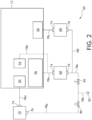
FIG. 2 is a schematic view of a sewage system for the recreational vehicle; -
FIG. 3 is a top view of a chassis assembly for the recreational vehicle; -
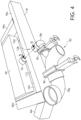
FIG. 4 is an enlarged perspective view of a portion of the chassis assembly; and -
FIG. 5 is a cross-section view of the chassis assembly taken along line 5-5 inFIG. 4 . - Turning to
FIG. 1 , arecreational vehicle 10 is shown that includes acabin 12 and achassis assembly 14 that supports thecabin 12. Thecabin 12 includes afirst shell member 20a and asecond shell member 20b that are separately molded and then assembled together to form amain body 22 ofcabin 12. Thecabin 12 further includes a plurality ofwindows 26 and adoor 28 for providing selective access to an interior of thecabin 12. Thechassis assembly 14 includes arigid chassis 34 that supports thecabin 12, and a plurality ofwheels 36 that are rotatably coupled to and support thechassis 34. - The
recreational vehicle 10 in the present example is a non-motorized trailer that offers mobile living accommodations within its interior (e.g., a kitchen, a bathroom, and one or more sleeping facilities) and can be coupled to a motorizedvehicle 40 for towing. However, therecreational vehicle 10 can be other types of recreational vehicles in other embodiments such as, for example, a self-propelled motorhome. - The
recreational vehicle 10 can include various utility systems for servicing thevehicle 10. For example, as shown inFIG. 2 , therecreational vehicle 10 in the present embodiment includes a plurality of fluid handling units (i.e., atoilet 50, a shower 52, abathroom sink 54, and a kitchen sink 56) and asewage system 60 for handling sewage from thefluid handling units - The
sewage system 60 includes afirst holding tank 66 that can receive and hold sewage from the shower 52 andbathroom sink 54; asecond holding tank 68 that can receive and hold sewage from thekitchen sink 56; and athird holding tank 70 that can receive and hold sewage from thetoilet 50. Eachholding tank single inlet 74 andsingle outlet 76. The shower 52 is fluidly coupled to theinlet 74 of thefirst holding tank 66 via asewage line 78a, and thebathroom sink 54 is fluidly coupled to theinlet 74 of thefirst holding tank 66 via asewage line 78b that feeds into thesewage line 78a. Thekitchen sink 56 andtoilet 50 are respectively fluidly coupled to theinlets 74 of the second andthird holding tanks sewage lines - The
sewage system 60 further includes adischarge outlet 82 and a pair ofvalves discharge outlet 82 and theholding tanks outlet 76 of thefirst holding tank 66 is fluidly coupled to an inlet of thevalve 84 via asewage line 78e, and theoutlet 76 of thesecond holding tank 68 is fluidly coupled to the inlet of thevalve 84 via asewage line 78f that feeds into thesewage line 78e. Moreover, theoutlet 76 of thethird holding tank 70 is fluidly coupled to an inlet of thevalve 86 via asewage line 78g. Finally, the outlets of thevalves common sewage line 78h that terminates at thedischarge outlet 82. - Each
valve - As discussed further below, the first and
second holding tanks sewage system 60 are mounted on thechassis 34 outside of thecabin 12. Indeed, most elements of thesewage system 60 in the present embodiment are arranged outside of thecabin 12 except for portions of thesewage lines 78a-d. However, it is to be appreciated that other portions of thesewage system 60 may be arranged within thecabin 12 in some embodiments without departing from the scope of the disclosure. Moreover, in some examples, theentire sewage system 60 can be arranged outside of thecabin 12. - The
sewage system 60 is preferably configured such that sewage within thesystem 60 will be biased towards thevalves discharge outlet 82 via gravity. For example, thevalves discharge outlet 82 can be arranged at elevations below thefluid handling devices fluid handling devices holding tanks valves discharge outlet 82. In this manner, sewage from thefluid handling devices system 60 toward thevalves discharge outlet 82. When thevalves fluid handling devices holding tanks valves system 60 will flow naturally toward and out of thedischarge outlet 82. - It is to be appreciated that one or more portions of the
sewage system 60 may convey fluid against gravity in some embodiments. For instance, certain segments of a sewage line 78 may convey sewage at an uphill slope. In such embodiments, thesewage system 60 may comprise one or more pumps that are operable to motivate sewage through thesystem 60. Moreover, it is to be appreciated that thesewage system 60 can comprise other numbers of holding tanks, valves, sewage lines, and discharge outlets than disclosed in the present embodiment. Broadly speaking, thesewage system 60 can comprise any configuration of one or more fluid elements that are configured and/or operable to convey sewage from one or more fluid handling devices of thevehicle 10 to one or more discharge outlets. - The
vehicle 10 can include other utility systems such as, for example, a water system for containing clean water and/or conveying water to its fluid handling devices; a gas system for storing gas (e.g., propane, natural gas, etc.) and/or supplying gas to one or more gas appliances (e.g., stove, furnace, etc.); or an electrical system for storing electricity and/or conveying electricity to one or more electric appliances (e.g., refrigerator, air conditioner, etc.). Moreover, each utility system of thevehicle 10 can comprise its own configuration of one or more utility members. For the purpose of this disclosure, a "utility member" is any element of a utility system configured to contain, store, and/or convey the system's associated commodity (e.g., water, electricity, gas, etc.) or influent (e.g., sewage). For instance, a utility member of thesewage system 60 would be any element of the system configured to contain and/or convey sewage from thefluid handling devices vehicle 10. - Turning to
FIG. 3 , thechassis assembly 14 of thevehicle 10 will now be described in further detail. Thewheels 36 of the assembly are coupled to opposite ends of anaxle 92, which is rotatably coupled to thechassis 34. Meanwhile, thechassis 34 comprises a plurality of beams 96 that are welded together to form a rigid body. - In particular, the
chassis 34 includes a plurality ofbeams 96a-c that extend longitudinally in a first direction Di; a plurality ofbeams 96d-j that extend longitudinally in a second direction D2 that is substantially perpendicular to the first direction Di; and a plurality ofbeams beams beams 96e-i form crossmembers within the frame that extend completely across the frame. - The beams 96 are preferably rectangular beams with a hollow interior to mitigate their weight. When arranged and welded together as shown in
FIG. 3 , the beams 96 can form a strong andrigid chassis 34 that can support thecabin 12 above. Moreover, thechassis 34 can include various mounting elements for supporting or fixing structure thereto. - For example, the
chassis 34 can include mountingbrackets 102 that are fixed to and extend along bottom sides of thebeams 96d-f for supporting the first andsecond holding tanks brackets 102 andbeams 96d-f can define receivingspaces second holding tanks second holding tanks brackets 102 and in some examples, be fixed to the mountingbrackets 102 and/or adjacent beams 96 using fasteners and/or straps that hold thetanks cabin 12 can then be mounted on thechassis 34 such that it sits over and covers thespaces tanks cabin 12 can be fixed to thechassis 34 using, for example, fasteners or other conventional means. - It is to be appreciated that the shape, number, and configuration of the beams 96 and any mounting structure for the
chassis 34 can vary by embodiment. Moreover, the beams 96 can be fixed together using other means besides welding such as, for example, fasteners. Broadly speaking, thechassis 34 can comprise any number and configuration of beams that are fixed together to form a rigid body for supporting thecabin 12. - As discussed above, the
recreational vehicle 10 can comprise one or more utility systems, each system comprising one or more utility members for containing, storing, and/or conveying the system's associated commodity or influent. In some cases, a utility member may be located under thecabin 12. However, the beams 96 of thechassis 34 may interfere with its placement. To avoid such interference, the utility member can be routed below one or more beams 96. However, the utility member at such a low elevation can get damaged if, for example, an object on the ground (or the ground itself) impacts the utility member. - In the present embodiment, the
sewage system 60 has multiple components arranged below thecabin 12, including the first andsecond holding tanks sewage lines sewage lines beams sewage lines beams sewage lines - As shown in the
FIGS. 4 and5 , thebeam 96c is a hollow, rectangular beam having anupper wall 112, abottom wall 114, afirst side wall 116, and asecond side wall 118 that collectively define aninterior space 120 of thebeam 96c. The first andsecond side walls second apertures sewage line 78e is routed through the first andsecond apertures sewage line 78e can extend across thebeam 96c without having to route it below, thereby mitigating a risk of the damage to thesewage line 78e. - Notably, the
apertures beam 96c as compared to a similar beam having solid walls without any apertures. Accordingly, areinforcement tube 132 may be provided in thespace 120 of thebeam 96c to preserve its strength. More specifically, thereinforcement tube 132 is a cylindrical body defining achannel 134 that is aligned with the first andsecond apertures sewage line 78e can extend therethrough. Thetube 132 has afirst end portion 136 that is provided in thefirst aperture 126 and welded to thefirst side wall 116; and asecond end portion 138 that is provided in thesecond aperture 128 and welded to thesecond side wall 118. To facilitate such welding, thereinforcement tube 132 preferably has an outer diameter that is substantially similar to but smaller than the inner diameters of the first andsecond apertures 126, 128 (for the purposes of this disclosure, two diameters are substantially similar if a difference between the diameters is ¼ inch or less, preferably 1/8 inch or less, and more preferably 1/16 inch or less). In this manner, thetube 132 can fit within the first andsecond apertures - The
tube 132 as configured can reinforce thebeam 96c at its points of attachment and thus compensate for any loss of strength that may occur due to the presence of theapertures beam 96c. For instance, thetube 132 may extend completely through one or bothapertures sides walls apertures - Still further, the
beam 96c can comprise other shapes and configurations with one or more apertures that permit thesewage line 78e to extend therethrough. For instance, thebeam 96c may be a solid wall with a single aperture that theline 78e passes through. Moreover, thebeam 96c can accommodate additional and/or alternative utility members through its aperture(s). For instance, thebeam 96c may accommodate different portions of thesewage system 60 therethrough and/or utility members of other systems (e.g., electrical wires of an electrical system, water lines of a water system, etc.). Broadly speaking, thebeam 96c can comprise any configuration defining one or more apertures that accommodate a utility member therethrough. The same applies for any other beam(s) 96 of thechassis 34. For instance, thebeam 96e of the present embodiment has a configuration similar to thebeam 96c which accommodates thesewage line 78f therethrough. - Illustrative embodiments have been described, hereinabove. It will be apparent to those skilled in the art that the above apparatuses and methods may incorporate changes and modifications without departing from the scope of this disclosure. The invention is therefore not limited to particular details of this disclosure, and will encompass modifications and adaptions thereof within the spirit and the scope of the appended claims.
Claims (15)
- A chassis for a recreational vehicle, comprising:a plurality of beams fixed together to form a rigid body, wherein at least one beam comprises a plurality of walls that define an interior space of the beam, the plurality of walls including a first wall and a second wall that respectively define a first aperture and second aperture; anda reinforcement tube provided in the interior space, the reinforcement tube defining a channel therethrough,wherein the first aperture, second aperture, and channel are aligned to accommodate a utility member therethrough.
- The chassis according to claim 1, wherein the reinforcement tube has a first end portion welded to the first wall and a second end portion welded to the second wall.
- The chassis according to claim 2, wherein the first end portion is provided in the first aperture and the second end portion is provided in the second aperture.
- The chassis according to claim 3, wherein:the first aperture has a first inner diameter,the second aperture has a second inner diameter, andthe reinforcement tube has an outer diameter that is substantially similar to but smaller than the first inner diameter and second inner diameter.
- A chassis assembly comprising:the chassis according to claim 1; andthe utility member extending through the first aperture, second aperture, and channel of the chassis.
- The chassis assembly according to claim 5, wherein the utility member is a sewage line.
- The chassis assembly according to claim 6, further comprising a holding tank supported by the chassis, wherein the sewage line is fluidly coupled to an outlet of the holding tank.
- The chassis assembly according to claim 7, wherein the chassis defines a receiving space that accommodates the holding tank.
- The chassis assembly according to claim 7, further comprising a discharge outlet, wherein the sewage line is fluidly coupled between the discharge outlet and holding tank such that fluid being conveyed from the holding tank to the discharge outlet passes through the sewage line and the first aperture, second aperture, and channel of the chassis.
- The chassis assembly according to claim 9, further comprising a valve fluidly coupled between the discharge outlet and the sewage line, the valve being operable between an open state and a closed state to provide selective fluid communication between the discharge outlet and the sewage line.
- A chassis assembly for a recreational vehicle, comprising:a chassis including a plurality of beams fixed together to form a rigid body, wherein at least one beam defines a first aperture; anda utility member extending through the first aperture.
- The chassis assembly according to claim 11, wherein the utility member is a sewage line.
- The chassis assembly according to claim 12, further comprising a holding tank supported by the chassis, wherein the sewage line is fluidly coupled to an outlet of the holding tank.
- The chassis assembly according to claim 13, wherein the chassis defines a receiving space that accommodates the holding tank.
- The chassis assembly according to claim 13, further comprising a discharge outlet, wherein the sewage line is fluidly coupled between the discharge outlet and holding tank such that fluid being conveyed from the holding tank to the discharge outlet passes through the sewage line and the first aperture of the chassis.
Applications Claiming Priority (1)
| Application Number | Priority Date | Filing Date | Title |
|---|---|---|---|
| US17/663,922 US20220274649A1 (en) | 2022-05-18 | 2022-05-18 | Chassis for recreational vehicle |
Publications (1)
| Publication Number | Publication Date |
|---|---|
| EP4279363A1 true EP4279363A1 (en) | 2023-11-22 |
Family
ID=83007016
Family Applications (1)
| Application Number | Title | Priority Date | Filing Date |
|---|---|---|---|
| EP23173436.9A Withdrawn EP4279363A1 (en) | 2022-05-18 | 2023-05-15 | Chassis for recreational vehicle |
Country Status (2)
| Country | Link |
|---|---|
| US (1) | US20220274649A1 (en) |
| EP (1) | EP4279363A1 (en) |
Citations (3)
| Publication number | Priority date | Publication date | Assignee | Title |
|---|---|---|---|---|
| US5135258A (en) * | 1989-06-29 | 1992-08-04 | Buxton Jon S | Trailer with fuel tanks and means for pumping fuel |
| EP1486401A1 (en) * | 2003-06-10 | 2004-12-15 | Deere & Company | Frame |
| DE102017106299A1 (en) * | 2017-03-23 | 2018-09-27 | Vöhringer GmbH & Co. KG | Multifunctional support of a substructure of a vehicle |
Family Cites Families (4)
| Publication number | Priority date | Publication date | Assignee | Title |
|---|---|---|---|---|
| US3051339A (en) * | 1957-12-30 | 1962-08-28 | Terho Mikko | Loading and unloading equipment for a motor truck |
| US20030085562A1 (en) * | 2001-11-02 | 2003-05-08 | Sparling James Douglas | Modular passenger semi-trailer with pneumatic unipoint suspension |
| FR2864808B1 (en) * | 2004-01-02 | 2006-03-10 | Renault Sas | FUEL TANK ARRANGEMENT IN A MOTOR VEHICLE |
| NL2027627B1 (en) * | 2021-02-23 | 2022-09-20 | Fortitude Holdings As | Apparatus and method for controlling weed growing on a ground surface |
-
2022
- 2022-05-18 US US17/663,922 patent/US20220274649A1/en not_active Abandoned
-
2023
- 2023-05-15 EP EP23173436.9A patent/EP4279363A1/en not_active Withdrawn
Patent Citations (3)
| Publication number | Priority date | Publication date | Assignee | Title |
|---|---|---|---|---|
| US5135258A (en) * | 1989-06-29 | 1992-08-04 | Buxton Jon S | Trailer with fuel tanks and means for pumping fuel |
| EP1486401A1 (en) * | 2003-06-10 | 2004-12-15 | Deere & Company | Frame |
| DE102017106299A1 (en) * | 2017-03-23 | 2018-09-27 | Vöhringer GmbH & Co. KG | Multifunctional support of a substructure of a vehicle |
Also Published As
| Publication number | Publication date |
|---|---|
| US20220274649A1 (en) | 2022-09-01 |
Similar Documents
| Publication | Publication Date | Title |
|---|---|---|
| US20240101015A1 (en) | Fluid transportation and delivery apparatus | |
| US9174531B2 (en) | Modular fuel storage system | |
| US20190126744A1 (en) | Vehicle fluid handling systems | |
| US20150035266A1 (en) | Integral tank in frame | |
| US20120012196A1 (en) | Water transport system | |
| US4332040A (en) | Self-contained, compact towable facility having maximized balanced water storage drain water collection and waste water isolation systems | |
| CN109073161A (en) | LNG truck and method for assembling LNG truck | |
| US6095429A (en) | Wheeled fire hydrant diffuser | |
| US20220274649A1 (en) | Chassis for recreational vehicle | |
| WO2019241643A1 (en) | Vertical fluid storage tank with connecting ports | |
| US3995871A (en) | Vapor recovery overturn rail | |
| CN112313113B (en) | Caravan with ladder-shaped frame | |
| JP2000190866A (en) | Working vehicle for rescue team | |
| US20260028076A1 (en) | Trailer System | |
| US20050087975A1 (en) | Fluid storage and transport system | |
| US20230098463A1 (en) | Chassis for recreational vehicles having a transport area for a fluid storage vessel | |
| US20220194290A1 (en) | Tank trailer with fluid collection system | |
| US20230356782A1 (en) | Chassis for recreational vehicles having a transport area for a fluid storage vessel | |
| US20170120796A1 (en) | Novel Frac Tank and Trailer Assembly | |
| AU2008255248A1 (en) | Pressure vessel | |
| EP1502785A1 (en) | Camping car or caravan with evaporative cooler | |
| US20040070264A1 (en) | Integrated air dryer module for vehicle air brake | |
| KR102543390B1 (en) | Fresh water tank assembly for camping vehicle | |
| US20200384906A1 (en) | Vacuum Tank Liquid Trailer | |
| US20050001078A1 (en) | Implement with plumbing lines through a main frame tube |
Legal Events
| Date | Code | Title | Description |
|---|---|---|---|
| PUAI | Public reference made under article 153(3) epc to a published international application that has entered the european phase |
Free format text: ORIGINAL CODE: 0009012 |
|
| STAA | Information on the status of an ep patent application or granted ep patent |
Free format text: STATUS: THE APPLICATION HAS BEEN PUBLISHED |
|
| AK | Designated contracting states |
Kind code of ref document: A1 Designated state(s): AL AT BE BG CH CY CZ DE DK EE ES FI FR GB GR HR HU IE IS IT LI LT LU LV MC ME MK MT NL NO PL PT RO RS SE SI SK SM TR |
|
| P01 | Opt-out of the competence of the unified patent court (upc) registered |
Effective date: 20231220 |
|
| STAA | Information on the status of an ep patent application or granted ep patent |
Free format text: STATUS: THE APPLICATION IS DEEMED TO BE WITHDRAWN |
|
| 18D | Application deemed to be withdrawn |
Effective date: 20240523 |