EP4279353A1 - Point machine and method for operating a point machine - Google Patents
Point machine and method for operating a point machine Download PDFInfo
- Publication number
- EP4279353A1 EP4279353A1 EP22174265.3A EP22174265A EP4279353A1 EP 4279353 A1 EP4279353 A1 EP 4279353A1 EP 22174265 A EP22174265 A EP 22174265A EP 4279353 A1 EP4279353 A1 EP 4279353A1
- Authority
- EP
- European Patent Office
- Prior art keywords
- point
- railway
- point machine
- rod
- detector rod
- Prior art date
- Legal status (The legal status is an assumption and is not a legal conclusion. Google has not performed a legal analysis and makes no representation as to the accuracy of the status listed.)
- Pending
Links
Images
Classifications
-
- B—PERFORMING OPERATIONS; TRANSPORTING
- B61—RAILWAYS
- B61L—GUIDING RAILWAY TRAFFIC; ENSURING THE SAFETY OF RAILWAY TRAFFIC
- B61L5/00—Local operating mechanisms for points or track-mounted scotch-blocks; Visible or audible signals; Local operating mechanisms for visible or audible signals
- B61L5/06—Electric devices for operating points or scotch-blocks, e.g. using electromotive driving means
-
- B—PERFORMING OPERATIONS; TRANSPORTING
- B61—RAILWAYS
- B61L—GUIDING RAILWAY TRAFFIC; ENSURING THE SAFETY OF RAILWAY TRAFFIC
- B61L27/00—Central railway traffic control systems; Trackside control; Communication systems specially adapted therefor
- B61L27/50—Trackside diagnosis or maintenance, e.g. software upgrades
- B61L27/53—Trackside diagnosis or maintenance, e.g. software upgrades for trackside elements or systems, e.g. trackside supervision of trackside control system conditions
-
- B—PERFORMING OPERATIONS; TRANSPORTING
- B61—RAILWAYS
- B61L—GUIDING RAILWAY TRAFFIC; ENSURING THE SAFETY OF RAILWAY TRAFFIC
- B61L5/00—Local operating mechanisms for points or track-mounted scotch-blocks; Visible or audible signals; Local operating mechanisms for visible or audible signals
- B61L5/10—Locking mechanisms for points; Means for indicating the setting of points
Definitions
- the invention relates to a point machine for moving a railway point, comprising at least one main rod that moves the railway point, at least one detector rod that is connected to the railway point and follows the movement of the railway point, and at least one locking device that can lock the movement of the detector rod in at least one predetermined locking position of the railway point.
- the invention relates to a method for operating a point machine, comprising at least one main rod that moves the railway point, at least one detector rod that is connected to the railway point and follows the movement of the railway point, and at least one locking device that can lock the movement of the detector rod in predetermined end positions of the railway point, the method comprises the following step: moving the railway point via the main rod.
- Such devices and methods are known from prior art and are used to move a railway point to its different positions.
- the point machine moves a switch blade of the railway point to its different end positions.
- the main rod is connected to the switch blade and moved by a driving motor of the point machine.
- the detector rod allows point machines to confirm that they are in their end position.
- the locking device locks the movement of the detector rod in the end positions. Therefore, the end positions are also called locking positions.
- There are gaps in the detector rod where the locking device fits in and locks the movement of the detector rod mechanically. Although the gaps in the detector rod are wider than the locking device, sometimes the position of the gap of the detector rod and the locking device does not fit and therefore the point machine cannot be locked. The reason for this can be different and is not completely known. In this case, the point machine reports a failure as it is not secured that its end position has been reached. Such failures stop the train traffic until maintenance has been done to the point machine and the locking device works properly.
- the invented solution has the advantage that it is very simple to install and therefore is not very cost effective.
- a displacement of the detector rod By measuring the position of the detector rod in the longitudinal direction, it is possible to detect a displacement of the detector rod relative to a reference position i.e., to the locking device.
- the reference position can for example be determined in an installation phase of the point machine and represents the position where the locking device fits in the gap in the detector rod and where the operation of the locking device is guaranteed.
- By implementing the sensor device it is possible to detect very early if a displacement relative to the reference position is happening.
- a small displacement does not mean a failure of the point immediately, because usually there is a small clearance.
- the clearance is made by design and is for example 2.5 mm. If the displacement above a predetermined amount is detected, further additional action can be done.
- a maintenance technician can be sent to the point machine and readjust the setting of the detector rod.
- the adjustment can be done more easily with the invention because the actual positioning of the detector rod can be seen permanently by the help of the first sensor device.
- an easy maintenance is possible.
- the first sensor device may comprise at least one linear encoder. This has the advantage that the position of the detector rod is available immediately also after restart of the sensor device and/or the point machine. Therefore, it is possible to switch off the point machine and the sensor device while it is not in use.
- the at least one detector rod comprises at least one adjustment device, which allows an adjustment of the length of the detector rod in the longitudinal direction.
- the adjustment device can for example be designed very simple as a clutch with an adjuster nut and lock nut, so that the distance of the clutch parts can be regulated by the adjuster nut.
- the point machine comprises at least one communication device, which can communicate data with an external device.
- the point machine comprises at least one second sensor device, which measures an ambient temperature.
- the temperature can influence the material of the detector rod and, therefore, its length. So it is useful to take this into account.
- the point machine comprises at least one evaluation device, which is connected to the first sensor device and is designed to evaluate the measured position of the detector rod relative to a reference position.
- the evaluation device is designed to evaluate a maintenance plan using the measured position, wherein the maintenance plan for example includes work instructions for adjusting the length of the detector rod.
- the maintenance plan can for example include instruction how many rotations of an adjuster nut in which direction are needed. Therefore, the maintenance worker can work faster and more accurate.
- an ambient temperature of the point machine can be measured by a second sensor device. This has the already further above-mentioned advantage that the temperature can be considered as the temperature can have an influence.
- evaluating a maintenance plan using the measured position wherein the maintenance plan includes work instructions for adjusting the length of the detector rod.
- the invention further relates to a computer program product, comprising instructions for performing the method of the above-mentioned embodiments.
- a railway facility 1 comprises railway tracks with railway points 2, one of these railway points 2 is shown in fig. 1 .
- This railway point 2 comprises a point machine 3, stock rails 4, and point blades 5, wherein the point machine 3 moves the point blades 5 between the stock rails 4.
- the point machine 3 comprises a housing 6, a drive motor 7, a main rod 8, and 2 detector rods 9.
- the main rod 8 is connected to the point blades 5 and driven by the drive motor 7 via a gear box 10. So, the main rod 8 is driven in a longitudinal direction 11 by the drive motor 7 to move the point blades 5 between its end positions. In each of the two end positions, one of the two point blades 5 is adjacent to one of the stock rails 4 in a well-known manner. Therefore, in the end positions a safe movement of the trains over the point is possible.
- the detector rods 9 are respectively connected to one of the point blades 5 and follow their movement. Therefore, by the detector rods 9 the position of the point blades 5 can be detected.
- the locking devices 12 respectively fit into gaps 13 in the detector rods 9. If the point blades 5 are in one of their end positions, the gap 13 is aligned with the locking device 12, and the locking device 12 is moved in a direction rectangular to the longitudinal direction 11 so that the detector rod 9 is mechanically locked.
- the point machine 3 further comprises first sensor devices 15.
- Each first sensor device 15 comprises at least one absolute linear encoder 16 that is fixed to the housing 6 and one magnetic slider 17 that is connected to the detector rod 9. By the sensor device 15 each movement of the detector rod 9 can be measured.
- To integrate the magnetic slider 17 it could be useful to extended the detector rods 9 and do some milling at the end to place the magnetic slider 17. It is also possible to place the first sensor devices 15 on different locations at the different detector rods 9. This can be advantageous if the space in the housing 6 is limited.
- the point machine 3 further comprises a second sensor device 18.
- the second sensor device 18 comprises at least one temperature sensor 19 that measures an ambient temperature.
- the second sensor device 18 is outside the housing 6, but it can alternatively also be in the housing 6.
- the point machine 3 further comprises an evaluation device 20 that is connected to the first sensor device 15 and the second sensor device 18.
- the connection can be done wirelessly.
- the evaluation device 20 is designed to evaluate the measured position of the detector rod relative to a reference position. This has the advantage that findings out of the measurements can be evaluated automatically.
- the evaluation device is designed to evaluate a maintenance plan using the measured position.
- the maintenance plan includes work instructions for adjusting the length of the detector rod. This has the advantage that a much faster maintenance is possible. Maintenance work on railway points has very often a lot of time pressure. Therefore, faster maintenance is very advantageous.
- every detector rod in the exemplary embodiment of the figures comprises one adjustment device 24.
- Each adjustment device 24 allows an adjustment of the length of the detector rod 9 in the longitudinal direction 11. This has the advantage that the position of the gap 13 can be changed very quick and easy.
- the adjustment is done by rotating a adjuster nut (not shown).
- a locking nut (not shown) for example locks the adjustment device 24 after the adjustment. By that it is guaranteed the no unintentional length change is done.
- the maintenance plan can for example include instructions how many rotations of the adjuster nut in which direction are needed. Therefore, the maintenance worker can change the length of the detector rod 9 very quickly.
- an automatic adjustment device could be included or a tool that automatically adjusts the adjustment device 24 according to the working plan of the evaluation device 20.
- the point machine 3 further comprises a communication device 21 by which data generated by the evaluation device 20 can be communicated externally.
- This communication can for example be to a cloud storage 22.
- the cloud storage 22 enables a long-term monitoring of the detector rods 9 generating useful insights on several railway points 2. For example, it generates a global view on the condition of several point machines 3 that are equipped with the invention.
- the data generated by the evaluation device 20 can be used for predictive maintenance of the point machine 3 and/or the whole railway facility 1. Further, via the temperature data gathered with the displacement information, it will be possible to predict the detector rods 9 displacement based on weather forecast. Finally, with all these information it could be possible to generate a planning for each technician to send them onsite and thus avoid as much as possible disruptions on the railway facility 1 while optimizing the schedule of every technician currently devoted to this task.
- the point machine 3 may further comprise a local visualization device 23, by which data or maintenance advice can be shown locally, for example to a service technician that works on the railway point 2.
- Figure 4 shows a side view of the detector rod 9 with its gap 13 and the locking device 12 that moves in the gap 13.
- the gap 13 has a width B in the longitudinal direction 11 of 21 mm.
- the locking device 12 has a width A in the longitudinal direction of 16 mm. thus, there is a designed clearance of 2.5 mm on each side of the locking device 12 in theory.
- the clearance can change. Due to the invention these changes do not lead to problems and down time of the railway point 2.
Landscapes
- Engineering & Computer Science (AREA)
- Mechanical Engineering (AREA)
- Health & Medical Sciences (AREA)
- Biomedical Technology (AREA)
- General Health & Medical Sciences (AREA)
- Train Traffic Observation, Control, And Security (AREA)
Abstract
Description
- The invention relates to a point machine for moving a railway point, comprising at least one main rod that moves the railway point, at least one detector rod that is connected to the railway point and follows the movement of the railway point, and at least one locking device that can lock the movement of the detector rod in at least one predetermined locking position of the railway point.
- Further, the invention relates to a method for operating a point machine, comprising at least one main rod that moves the railway point, at least one detector rod that is connected to the railway point and follows the movement of the railway point, and at least one locking device that can lock the movement of the detector rod in predetermined end positions of the railway point, the method comprises the following step: moving the railway point via the main rod.
- Such devices and methods are known from prior art and are used to move a railway point to its different positions. The point machine moves a switch blade of the railway point to its different end positions. The main rod is connected to the switch blade and moved by a driving motor of the point machine. The detector rod allows point machines to confirm that they are in their end position. The locking device locks the movement of the detector rod in the end positions. Therefore, the end positions are also called locking positions. There are gaps in the detector rod where the locking device fits in and locks the movement of the detector rod mechanically. Although the gaps in the detector rod are wider than the locking device, sometimes the position of the gap of the detector rod and the locking device does not fit and therefore the point machine cannot be locked. The reason for this can be different and is not completely known. In this case, the point machine reports a failure as it is not secured that its end position has been reached. Such failures stop the train traffic until maintenance has been done to the point machine and the locking device works properly.
- Therefore, it is the purpose of the present invention to provide a point machine and the method of the above-mentioned type in order to reduce the number of failures in operation.
- The problem is solved by the subject matter of the independent patent claims.
- The invented solution has the advantage that it is very simple to install and therefore is not very cost effective. By measuring the position of the detector rod in the longitudinal direction, it is possible to detect a displacement of the detector rod relative to a reference position i.e., to the locking device. The reference position can for example be determined in an installation phase of the point machine and represents the position where the locking device fits in the gap in the detector rod and where the operation of the locking device is guaranteed. By implementing the sensor device, it is possible to detect very early if a displacement relative to the reference position is happening. A small displacement does not mean a failure of the point immediately, because usually there is a small clearance. The clearance is made by design and is for example 2.5 mm. If the displacement above a predetermined amount is detected, further additional action can be done. For example, a maintenance technician can be sent to the point machine and readjust the setting of the detector rod. During this maintenance work, the adjustment can be done more easily with the invention because the actual positioning of the detector rod can be seen permanently by the help of the first sensor device. Thus, an easy maintenance is possible.
- The invention can be extended by the following advantageous embodiments.
- In one embodiment, the first sensor device may comprise at least one linear encoder. This has the advantage that the position of the detector rod is available immediately also after restart of the sensor device and/or the point machine. Therefore, it is possible to switch off the point machine and the sensor device while it is not in use.
- In another embodiment, the at least one detector rod comprises at least one adjustment device, which allows an adjustment of the length of the detector rod in the longitudinal direction. This has the advantage that a displacement of the detector rod can be maintained very quickly and easily. The adjustment device can for example be designed very simple as a clutch with an adjuster nut and lock nut, so that the distance of the clutch parts can be regulated by the adjuster nut.
- Further, in order to transfer the measured data to a separate device or database, the point machine comprises at least one communication device, which can communicate data with an external device.
- In another advantageous embodiment, the point machine comprises at least one second sensor device, which measures an ambient temperature. This has the advantage that also the temperature is monitored. The temperature can influence the material of the detector rod and, therefore, its length. So it is useful to take this into account.
- In another embodiment, the point machine comprises at least one evaluation device, which is connected to the first sensor device and is designed to evaluate the measured position of the detector rod relative to a reference position. This has the advantage that findings out of the measurements can be evaluated automatically. For example, the evaluation device is designed to evaluate a maintenance plan using the measured position, wherein the maintenance plan for example includes work instructions for adjusting the length of the detector rod. This has the advantage that a much faster maintenance is possible. Maintenance work on railway points has very often a lot of time pressure. Therefore, faster maintenance is very useful. The maintenance plan can for example include instruction how many rotations of an adjuster nut in which direction are needed. Therefore, the maintenance worker can work faster and more accurate.
- In an embodiment of the inventive method, an ambient temperature of the point machine can be measured by a second sensor device. This has the already further above-mentioned advantage that the temperature can be considered as the temperature can have an influence.
- In another embodiment, evaluating a maintenance plan using the measured position, wherein the maintenance plan includes work instructions for adjusting the length of the detector rod. This has the already above-mentioned advantage that the maintenance work can be accelerated.
- Finally, the invention further relates to a computer program product, comprising instructions for performing the method of the above-mentioned embodiments.
- In the following, the invention will be further described related to the exemplary embodiment in the attached drawings.
- It shows:
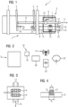
- Fig. 1
- schematic drawing of an exemplary embodiment of a point machine according to the invention;
- Fig. 2
- schematic detailed drawing of the point machine of
fig. 1 ; - Fig. 3
- a schematic drawing of the point machine of
fig. 2 with additional details; - Fig. 4
- a side view of
fig. 3 . - In the following, the invention is described related to the exemplary embodiment in
fig. 1 to fig. 4 . - A
railway facility 1 comprises railway tracks withrailway points 2, one of theserailway points 2 is shown infig. 1 . Thisrailway point 2 comprises apoint machine 3,stock rails 4, andpoint blades 5, wherein thepoint machine 3 moves thepoint blades 5 between thestock rails 4. - The
point machine 3 comprises ahousing 6, adrive motor 7, amain rod detector rods 9. Themain rod 8 is connected to thepoint blades 5 and driven by thedrive motor 7 via agear box 10. So, themain rod 8 is driven in alongitudinal direction 11 by thedrive motor 7 to move thepoint blades 5 between its end positions. In each of the two end positions, one of the twopoint blades 5 is adjacent to one of the stock rails 4 in a well-known manner. Therefore, in the end positions a safe movement of the trains over the point is possible. - The
detector rods 9 are respectively connected to one of thepoint blades 5 and follow their movement. Therefore, by thedetector rods 9 the position of thepoint blades 5 can be detected. Within thehousing 6 of thepoint machine 3 there are two lockingdevices 12. Thelocking devices 12 respectively fit intogaps 13 in thedetector rods 9. If thepoint blades 5 are in one of their end positions, thegap 13 is aligned with the lockingdevice 12, and thelocking device 12 is moved in a direction rectangular to thelongitudinal direction 11 so that thedetector rod 9 is mechanically locked. - The
point machine 3 according to the invention further comprisesfirst sensor devices 15. Eachfirst sensor device 15 comprises at least one absolutelinear encoder 16 that is fixed to thehousing 6 and onemagnetic slider 17 that is connected to thedetector rod 9. By thesensor device 15 each movement of thedetector rod 9 can be measured. To integrate themagnetic slider 17 it could be useful to extended thedetector rods 9 and do some milling at the end to place themagnetic slider 17. It is also possible to place thefirst sensor devices 15 on different locations at thedifferent detector rods 9. This can be advantageous if the space in thehousing 6 is limited. - The
point machine 3 according to the invention further comprises asecond sensor device 18. Thesecond sensor device 18 comprises at least onetemperature sensor 19 that measures an ambient temperature. In the exemplary embodiment in the figures thesecond sensor device 18 is outside thehousing 6, but it can alternatively also be in thehousing 6. - The
point machine 3 further comprises anevaluation device 20 that is connected to thefirst sensor device 15 and thesecond sensor device 18. Advantageously, the connection can be done wirelessly. Theevaluation device 20 is designed to evaluate the measured position of the detector rod relative to a reference position. This has the advantage that findings out of the measurements can be evaluated automatically. In the exemplary embodiment of the figures the evaluation device is designed to evaluate a maintenance plan using the measured position. The maintenance plan includes work instructions for adjusting the length of the detector rod. This has the advantage that a much faster maintenance is possible. Maintenance work on railway points has very often a lot of time pressure. Therefore, faster maintenance is very advantageous. - Further, every detector rod in the exemplary embodiment of the figures comprises one
adjustment device 24. Eachadjustment device 24 allows an adjustment of the length of thedetector rod 9 in thelongitudinal direction 11. This has the advantage that the position of thegap 13 can be changed very quick and easy. The adjustment is done by rotating a adjuster nut (not shown). A locking nut (not shown) for example locks theadjustment device 24 after the adjustment. By that it is guaranteed the no unintentional length change is done. - The maintenance plan can for example include instructions how many rotations of the adjuster nut in which direction are needed. Therefore, the maintenance worker can change the length of the
detector rod 9 very quickly. In a future embodiment an automatic adjustment device could be included or a tool that automatically adjusts theadjustment device 24 according to the working plan of theevaluation device 20. - The
point machine 3 further comprises acommunication device 21 by which data generated by theevaluation device 20 can be communicated externally. This communication can for example be to acloud storage 22. Thecloud storage 22 enables a long-term monitoring of thedetector rods 9 generating useful insights on several railway points 2. For example, it generates a global view on the condition ofseveral point machines 3 that are equipped with the invention. The data generated by theevaluation device 20 can be used for predictive maintenance of thepoint machine 3 and/or thewhole railway facility 1. Further, via the temperature data gathered with the displacement information, it will be possible to predict thedetector rods 9 displacement based on weather forecast. Finally, with all these information it could be possible to generate a planning for each technician to send them onsite and thus avoid as much as possible disruptions on therailway facility 1 while optimizing the schedule of every technician currently devoted to this task. - Additionally or alternatively, the
point machine 3 may further comprise alocal visualization device 23, by which data or maintenance advice can be shown locally, for example to a service technician that works on therailway point 2. -
Figure 4 shows a side view of thedetector rod 9 with itsgap 13 and thelocking device 12 that moves in thegap 13. In the exemplary embodiment of the figures thegap 13 has a width B in thelongitudinal direction 11 of 21 mm. The lockingdevice 12 has a width A in the longitudinal direction of 16 mm. thus, there is a designed clearance of 2.5 mm on each side of thelocking device 12 in theory. However, as already mentioned during service of therailway point 2 the clearance can change. Due to the invention these changes do not lead to problems and down time of therailway point 2.
Claims (11)
- Point machine (3) for moving a railway point (2), comprisingat least one main rod (8) that moves the railway point (2), at least one detector rod (9) that is connected to the railway point (2) and follows the movement of the railway point (2), andat least one locking device (12) that can lock the movement of the detector rod (9) in at least one predetermined locking position of the railway point (2),characterised in thatthe point machine (3) comprises at least one first sensor device (15) which is designed to measure the position of the at least one detector rod (9) in a longitudinal direction (11) in the locking position.
- Point machine (3) according to claim 1,
characterised in that
the first sensor device (15) comprises at least one absolute linear encoder (16). - Point machine (3) according to claim 1 or 2,
characterised in that
the at least one detector rod (9) comprises at least one adjustment device (24), which allows an adjustment of the length of the detector rod (9) in the longitudinal direction (11) . - Point machine (3) according to one of the preceding claims,
characterised in that
the point machine (3) comprises at least one second sensor device (18), which measures an ambient temperature. - Point machine (3) according to one of the preceding claims,
characterised in that
the point machine (3) comprises at least one communication device (21), which can communicate data with an external device. - Point machine (3) according to one of the preceding claims,
characterised in that
the point machine (3) comprises at least one evaluation device (20), which is connected to the first sensor device (15) and is designed to evaluate the measured position of the detector rod (9) relative to a reference position. - Point machine (3) according to claim 6,
characterised in that
the evaluation device (20) is designed to evaluate a maintenance plan using the measured position, wherein the maintenance plan includes work instructions for adjusting the length of the detector rod (9). - Method for operating a point machine (3) comprising at least one main rod (8) that moves the railway point (2), at least one detector rod (9) that is connected to the railway point (2) and follows the movement of the railway point (2), andat least one locking device (12) that can lock the movement of the detector rod (9) in predetermined end positions of the railway point (2),the method comprises the following steps:- moving the railway point (2) via the main rod (8),characterised in that- measuring the position of the at least one detector rod (9) in a longitudinal direction (11) in the locking position of the railway point (2) by a first sensor device (15).
- Method according to claim 8,
characterised in that
measuring an ambient temperature of the point machine (3) by a second sensor device (18). - Method according to claim 8 or 9,
characterised in that
evaluating a maintenance plan using the measured position, wherein the maintenance plan includes work instructions for adjusting the length of the detector rod (9). - Computer program product comprising instructions for performing the method according to claims 8 to 10.
Priority Applications (1)
| Application Number | Priority Date | Filing Date | Title |
|---|---|---|---|
| EP22174265.3A EP4279353A1 (en) | 2022-05-19 | 2022-05-19 | Point machine and method for operating a point machine |
Applications Claiming Priority (1)
| Application Number | Priority Date | Filing Date | Title |
|---|---|---|---|
| EP22174265.3A EP4279353A1 (en) | 2022-05-19 | 2022-05-19 | Point machine and method for operating a point machine |
Publications (1)
| Publication Number | Publication Date |
|---|---|
| EP4279353A1 true EP4279353A1 (en) | 2023-11-22 |
Family
ID=81749549
Family Applications (1)
| Application Number | Title | Priority Date | Filing Date |
|---|---|---|---|
| EP22174265.3A Pending EP4279353A1 (en) | 2022-05-19 | 2022-05-19 | Point machine and method for operating a point machine |
Country Status (1)
| Country | Link |
|---|---|
| EP (1) | EP4279353A1 (en) |
Cited By (2)
| Publication number | Priority date | Publication date | Assignee | Title |
|---|---|---|---|---|
| EP4585490A1 (en) | 2024-01-15 | 2025-07-16 | Siemens Mobility GmbH | Method for point diagnosis for a railway switch, simulation model and computing device |
| WO2025181340A1 (en) * | 2024-02-29 | 2025-09-04 | Voestalpine Signaling Sainerholz Gmbh | Method for carrying out inspections of safety-relevant states |
Citations (4)
| Publication number | Priority date | Publication date | Assignee | Title |
|---|---|---|---|---|
| JP2000159106A (en) * | 1998-11-26 | 2000-06-13 | Railway Technical Res Inst | Lock out-of-lock detector and setting method of lock out-of-order judgment value |
| WO2002090166A1 (en) * | 2001-05-08 | 2002-11-14 | Safetran Systems Corporation | Condition monitoring system |
| DE202010010698U1 (en) * | 2010-06-22 | 2011-11-14 | Vae Gmbh | Device for end position testing of moving parts of a rail switch |
| CN114089215A (en) * | 2020-10-19 | 2022-02-25 | 广东毓秀科技有限公司 | A cluster-based fault identification method for switch machines |
-
2022
- 2022-05-19 EP EP22174265.3A patent/EP4279353A1/en active Pending
Patent Citations (4)
| Publication number | Priority date | Publication date | Assignee | Title |
|---|---|---|---|---|
| JP2000159106A (en) * | 1998-11-26 | 2000-06-13 | Railway Technical Res Inst | Lock out-of-lock detector and setting method of lock out-of-order judgment value |
| WO2002090166A1 (en) * | 2001-05-08 | 2002-11-14 | Safetran Systems Corporation | Condition monitoring system |
| DE202010010698U1 (en) * | 2010-06-22 | 2011-11-14 | Vae Gmbh | Device for end position testing of moving parts of a rail switch |
| CN114089215A (en) * | 2020-10-19 | 2022-02-25 | 广东毓秀科技有限公司 | A cluster-based fault identification method for switch machines |
Cited By (2)
| Publication number | Priority date | Publication date | Assignee | Title |
|---|---|---|---|---|
| EP4585490A1 (en) | 2024-01-15 | 2025-07-16 | Siemens Mobility GmbH | Method for point diagnosis for a railway switch, simulation model and computing device |
| WO2025181340A1 (en) * | 2024-02-29 | 2025-09-04 | Voestalpine Signaling Sainerholz Gmbh | Method for carrying out inspections of safety-relevant states |
Similar Documents
| Publication | Publication Date | Title |
|---|---|---|
| EP4279353A1 (en) | Point machine and method for operating a point machine | |
| CA3218228C (en) | Laboratory testing-based valve prognostics | |
| US11668192B2 (en) | Tunnel boring machine and tunnelling method | |
| Wang et al. | Early failure analysis of machining centers: a case study | |
| JP7179444B2 (en) | Sign detection system and sign detection method | |
| DE102008029672B3 (en) | Device and method for condition monitoring and condition diagnosis of a machine, machine component or system | |
| AU2019269456B2 (en) | Method and apparatus for monitoring a state of a passenger transport system by using a digital double | |
| JP2017097839A (en) | Abnormality analysis system and analysis apparatus | |
| CN111003022B (en) | Magnetic grid measurement-based turnout operation overall process monitoring method and device | |
| CA2944774C (en) | Data collection system and method | |
| EP3650388B1 (en) | A method and a system for detecting a malfunction of an elevator system | |
| KR20080000603A (en) | Predictive Maintenance Method | |
| KR102404889B1 (en) | Field Data Based Equipment Life Prediction System and Prediction Method of the Same | |
| Lesage et al. | Maintenance & quality control: a first methodological approach for maintenance policy optimization | |
| CN110427011A (en) | A kind of intelligent monitoring for automation equipment and real-time compensation system and method | |
| US20190242785A1 (en) | Method for Configuring and Monitoring an Installation | |
| Starr et al. | Failure analysis of mature robots in automated production | |
| GB2313611A (en) | Monitoring railway point electric operating mechanisms | |
| Johansson et al. | Context driven remaining useful life estimation | |
| US20250328128A1 (en) | Method and device for detecting measurement data of a machine, and tire heating press having a device for detecting measurement data | |
| CN112996708A (en) | Switch machine arrangement and method for diagnosing a switch | |
| US6028304A (en) | Precision displacement reference system | |
| Bhardwaj et al. | Computational study reliability of diesel engine through electrical assembly | |
| CN120316955A (en) | Method, simulation model and calculation unit for switch diagnosis of railway switches | |
| Al-Najjar | Establishing and running a condition-based maintenance policy: applied example of vibration-based maintenance |
Legal Events
| Date | Code | Title | Description |
|---|---|---|---|
| PUAI | Public reference made under article 153(3) epc to a published international application that has entered the european phase |
Free format text: ORIGINAL CODE: 0009012 |
|
| STAA | Information on the status of an ep patent application or granted ep patent |
Free format text: STATUS: THE APPLICATION HAS BEEN PUBLISHED |
|
| AK | Designated contracting states |
Kind code of ref document: A1 Designated state(s): AL AT BE BG CH CY CZ DE DK EE ES FI FR GB GR HR HU IE IS IT LI LT LU LV MC MK MT NL NO PL PT RO RS SE SI SK SM TR |
|
| STAA | Information on the status of an ep patent application or granted ep patent |
Free format text: STATUS: REQUEST FOR EXAMINATION WAS MADE |
|
| 17P | Request for examination filed |
Effective date: 20231205 |
|
| RBV | Designated contracting states (corrected) |
Designated state(s): AL AT BE BG CH CY CZ DE DK EE ES FI FR GB GR HR HU IE IS IT LI LT LU LV MC MK MT NL NO PL PT RO RS SE SI SK SM TR |
|
| RAP3 | Party data changed (applicant data changed or rights of an application transferred) |
Owner name: SIEMENS MOBILITY GMBH |