EP4279302A1 - Air outlet assembly, and vehicle - Google Patents
Air outlet assembly, and vehicle Download PDFInfo
- Publication number
- EP4279302A1 EP4279302A1 EP21918243.3A EP21918243A EP4279302A1 EP 4279302 A1 EP4279302 A1 EP 4279302A1 EP 21918243 A EP21918243 A EP 21918243A EP 4279302 A1 EP4279302 A1 EP 4279302A1
- Authority
- EP
- European Patent Office
- Prior art keywords
- air outlet
- air
- channel
- main body
- body component
- Prior art date
- Legal status (The legal status is an assumption and is not a legal conclusion. Google has not performed a legal analysis and makes no representation as to the accuracy of the status listed.)
- Granted
Links
Images


Classifications
-
- B—PERFORMING OPERATIONS; TRANSPORTING
- B60—VEHICLES IN GENERAL
- B60H—ARRANGEMENTS OF HEATING, COOLING, VENTILATING OR OTHER AIR-TREATING DEVICES SPECIALLY ADAPTED FOR PASSENGER OR GOODS SPACES OF VEHICLES
- B60H1/00—Heating, cooling or ventilating devices
- B60H1/34—Nozzles; Air-diffusers
-
- B—PERFORMING OPERATIONS; TRANSPORTING
- B60—VEHICLES IN GENERAL
- B60H—ARRANGEMENTS OF HEATING, COOLING, VENTILATING OR OTHER AIR-TREATING DEVICES SPECIALLY ADAPTED FOR PASSENGER OR GOODS SPACES OF VEHICLES
- B60H1/00—Heating, cooling or ventilating devices
- B60H1/34—Nozzles; Air-diffusers
- B60H1/3414—Nozzles; Air-diffusers with means for adjusting the air stream direction
- B60H1/3428—Nozzles; Air-diffusers with means for adjusting the air stream direction using a set of pivoting shutters and a pivoting frame
-
- B—PERFORMING OPERATIONS; TRANSPORTING
- B60—VEHICLES IN GENERAL
- B60H—ARRANGEMENTS OF HEATING, COOLING, VENTILATING OR OTHER AIR-TREATING DEVICES SPECIALLY ADAPTED FOR PASSENGER OR GOODS SPACES OF VEHICLES
- B60H1/00—Heating, cooling or ventilating devices
- B60H1/34—Nozzles; Air-diffusers
- B60H2001/3471—Details of actuators
- B60H2001/3478—Details of actuators acting on additional damper doors
Definitions
- the present invention relates to the field of vehicles, in particular to an air outlet assembly, and a vehicle.
- an air outlet of a traditional car has mainly guided air by virtue of an air outlet blade, and an air outlet assembly has been fixed to an instrument desk or an auxiliary instrument desk so as to be incapable of rotating.
- an air flow at an air outlet has to be upwards blown over the head and downwards blown to the waist. Due to such a demand, the arrangement position of the outlet is limited, and facilitate the development of modeling creativity is also limited by the exposed blade.
- the present invention is proposed to provide an air outlet assembly overcoming the above-mentioned problems or at least partially solving the above-mentioned problems, and a vehicle.
- One objective of a first aspect of the present invention is to provide a novel air outlet assembly capable of reducing the limitations on the arrangement position of an outlet, and facilitating the development of modeling creativity.
- the other objective of the present invention is to widen a coverage range of an air flow at an air outlet.
- One objective of a second aspect of the present invention is to provide a vehicle including the above-mentioned air outlet assembly.
- the vehicle is little in limitations on the arrangement position of an outlet, and facilitates the development of modeling creativity.
- an air outlet assembly including:
- the end, close to the driver compartment, of the air channel is configured to gradually expand in a direction pointing to the driver compartment, and an appearance of the end, close to the driver compartment, of the air outlet main body component is configured to gradually shrink in the direction pointing to the driver compartment, so that an expansion opening is formed in the end, close to the driver compartment, of the second channel.
- the air outlet assembly further includes:
- the at least one damper blade is configured to block the air channel when the air outlet main body component is located on an initial position and to be in gradual communication with the air channel when the air outlet main body component moves from the initial position to the driver compartment.
- the at least one damper blade is further configured to be in communication with the air channel to the greatest extent when the air outlet main body component moves to be partially exposed out of the instrument panel decorative plate.
- the air outlet main body component includes: an air outlet housing in which the first channel is formed, the second channel being formed by an outer surface of the air outlet housing and the inner wall face of the air channel.
- a plurality of air outlet nozzles configured to partition an air flow inside the first channel into a plurality of paths of air flows are formed on the end, close to the driver compartment, of the air outlet housing.
- each of the air outlet nozzles is configured to gradually shrink in the direction pointing to the driver compartment.
- the air outlet main body component further includes:
- the air outlet main body component further includes:
- the first rotating shafts are arranged in the transverse direction of the vehicle, and the second rotating shafts are arranged in the vertical direction of the vehicle.
- the linkage mechanism includes:
- the gear sheet is sheet-like, and the thickness direction thereof is parallel to the axes of the third rotating shafts; and the number of the second gears is two, and the two second gears are respectively arranged on two sides in the width direction of the gear sheet and are respectively meshed with the second gear teeth opposite thereto.
- the air outlet assembly further includes:
- the other aspect of an embodiment of the present invention provides a vehicle, including an air conditioner air guide pipe and any one air outlet assembly mentioned above.
- one air outlet main body component is arranged alone in the air channel in the instrument panel decorative plate, and the air outlet main body component is capable of moving and rotating relative to the instrument panel decorative plate.
- the position and orientation of the first channel inside the air outlet main body component are changed by controlling the movement and rotation of the air outlet main body component, and thus, flowing directions of air flows in the first channel and the second channel and a coverage range of an air flow flowing out of the air outlet assembly are changed.
- the present invention provides a brand new air outlet assembly, that is, the air outlet main body component is arranged alone in the instrument panel decorative plate, and the air direction and the coverage range of the air flow are adjusted by controlling the movement and rotation of the air outlet main body component, so that the coverage range of the air flow is widened, the comfort level of a user is improved, the arrangement position of an air outlet can be selected within a wider range, there are more choices for the modeling creativity of the air outlet, and the development of the modeling creativity is facilitated.
- an appearance of a front end of the air outlet main body component (which is specifically the air outlet housing of the air outlet main body component) gradually shrinks in a direction pointing to the driver compartment, and the end, close to the driver compartment, of the air channel at the inside of the instrument panel decorative plate gradually expands in the direction pointing to the driver compartment, so that an expansion opening is formed in the end, close to the driver compartment, of the second channel formed between the air outlet housing and the instrument panel decorative plate, and then, the coverage range of the air flow is widened.
- the air flow is jointly guided by the modeling of the instrument panel decorative plate and the appearance of the air outlet main body component, the traditional blade modeling is abandoned, and the selectivity of the modeling creativity of the air outlet is further enriched.
- a plurality of air outlet nozzles configured to partition an air flow inside the first channel into a plurality of paths of air flows are formed on the end, close to the driver compartment, of the air outlet housing.
- the plurality of air outlet nozzles formed on the air outlet housing can effectively disperse the air flow into a plurality of air paths to increase the flow velocity of the air flow here, so that warm air or cold air rapidly and centrally blows to the driver compartment, and the user experience is improved.
- the air outlet nozzles are all configured to gradually shrink in the direction pointing to the driver compartment, in this way, the cross section of an air flow channel can be further reduced, the air flow can be better centralized, and the flow velocity can be increased.
- FIG. 1 is a cross-sectional view of an air outlet assembly 100 and an air conditioner air guide pipe 200 according to an embodiment of the present invention.
- FIG. 2 is a cross-sectional view shown when an air outlet main body component 20 of the air outlet assembly 100 rotates to a first angle according to an embodiment of the present invention.
- FIG. 3 is a cross-sectional view shown when the air outlet main body component 20 of the air outlet assembly 100 rotates to a second angle according to an embodiment of the present invention. Arrows in FIG. 1 to FIG. 3 represent a trend of an air flow.
- the air outlet assembly 100 in the present invention includes an instrument panel decorative plate 10 and the air outlet main body component 20.
- An air channel which is in communication with the air conditioner air guide pipe 200 of a vehicle is arranged at the inside of the instrument panel decorative plate 10, and an opening at the end, away from the air conditioner air guide pipe 200, of the air channel faces a driver compartment.
- the air outlet main body component 20 is arranged in the air channel.
- a first channel which is capable of being opened and closed is arranged in the air outlet main body component 20, a second channel is formed by an outer surface of the air outlet main body component 20 and an inner wall face of the air channel, and the air outlet main body component 20 is configured to be controlled to move in the axial direction of the air channel and rotate around a preset axis (as shown in FIG. 2 and FIG. 3 ).
- the preset axis is parallel to a vertical plane in the axial direction of the air channel.
- the shape of the air outlet main body component 20 can be adaptively designed according to the shape of the air channel, for example, when the air channel is a square channel, the air outlet main body component 20 can also be set to be of an approximately square shape, and when the air channel is shaped like a circular pipe, the air outlet main body component 20 can also be set to have a circular cross section.
- the air outlet main body component 20 in this position state makes an air flow basically blown out in the axial direction of the air channel.
- the air outlet main body component 20 in FIG. 2 upwarps so that the air flow is obliquely and upwards blown out from the second channel and the first channel which are located above the air outlet main body component 20.
- the air outlet main body component 20 in FIG. 3 is downwards inclined so that the air flow is obliquely and downwards blown out from the second channel and the first channel which are located below the air outlet main body component 20.
- the air outlet main body component 20 moves forwards and backwards so that the air outlet assembly 100 can cover an air flow direction within a wider range.
- one air outlet main body component 20 is arranged alone in the air channel in the instrument panel decorative plate 10, and the air outlet main body component 20 is capable of moving and rotating relative to the instrument panel decorative plate 10.
- the position and orientation of the first channel inside the air outlet main body component 20 are changed by controlling the movement and rotation of the air outlet main body component 20, and thus, flowing directions of air flows in the first channel and the second channel and a coverage range of an air flow flowing out of the air outlet assembly 100 are changed.
- the present invention provides a brand new air outlet assembly 100, that is, the air outlet main body component 20 is arranged alone in the instrument panel decorative plate 10, and the air direction and the coverage range of the air flow are adjusted by controlling the movement and rotation of the air outlet main body component 20, so that the coverage range of the air flow is widened, the comfort level of a user is improved, the arrangement position of an air outlet can be selected within a wider range, there are more choices for the modeling creativity of the air outlet, and the development of the modeling creativity is facilitated.
- the end, close to the driver compartment, of the air channel is configured to gradually expand in a direction pointing to the driver compartment, and an appearance of the end, close to the driver compartment, of the air outlet main body component 20 is configured to gradually shrink in the direction pointing to the driver compartment, so that an expansion opening is formed in the end, close to the driver compartment, of the second channel.
- the instrument panel decorative plate 10 it is equivalent to arrangement of a flanging for guidance at the end, close to the driver compartment, of the instrument panel decorative plate 10.
- a space is left between the air outlet main body component 20 and the instrument panel decorative plate 10 to enable the air flow to flow along a surface of the flanging, so that an area covered by the air flow is further expanded.
- the air flow is jointly guided by the modeling of the instrument panel decorative plate 10 and the appearance of the air outlet main body component 20, the traditional blade modeling is abandoned, and the selectivity of the modeling creativity of the air outlet is further enriched.
- FIG. 4 is a schematic structural view of the air outlet assembly 100 and the air conditioner air guide pipe 200 according to an embodiment of the present invention.
- the air outlet assembly 100 further includes at least one damper blade 30 rotatably connected to the inside of the air channel (with reference to FIG. 1 ) and configured to be in communication with or block the air channel.
- the air outlet assembly 100 further includes a linkage mechanism 40 configured to connect the at least one damper blade 30 and the air outlet main body component 20, so that the air outlet main body component 20 drives the at least one damper blade 30 to rotate during movement.
- the at least one damper blade 30 is configured to block the air channel when the air outlet main body component 20 is located on an initial position and to be in gradual communication with the air channel when the air outlet main body component 20 moves from the initial position to the driver compartment. It can be imagined that the air channel can be completely closed when the damper blades 30 rotate for 90° clockwise or counterclockwise from a state in FIG. 1 . Due to the arrangement of the linkage mechanism 40, the movement of the air outlet main body component 20 may drive the rotation of the damper blades 30, and then, the flow rate of the air flow is distributed, that is, the amount and angle of the air flow flowing out of the damper blades 30 are controlled.
- the damper blades 30 may also be rotatably connected to the air conditioner air guide pipe 200 to control the blockage or communication of the air channel inside the air conditioner air guide pipe 200.
- the damper blades 30 are arranged in the air channel of the instrument panel decorative plate 10 to conveniently form an assembly with the air outlet assembly 100, thereby facilitating assembly.
- the at least one damper blade 30 is further configured to be in communication with the air channel to the greatest extent when the air outlet main body component 20 moves to be partially exposed out of the instrument panel decorative plate 10 (with reference to FIG. 4 ), at the moment, states of the damper blades 30 are shown in FIG. 1 .
- the position of the air outlet main body component 20 and the states of the damper blades 30 can also be correspondingly set, for example, the damper blades 30 are completely opened when the front end of the air outlet main body component 20 is flushed with the instrument panel decorative plate 10.
- the position of the air outlet main body component 20 and the states of the damper blades 30 of the air outlet assembly 100 on a different position can also be designed to be the same or different, and thus, the comfort level is improved.
- the air outlet main body component 20 includes an air outlet housing 21 in which the first channel is formed, the second channel is formed by an outer surface of the air outlet housing 21 and the inner wall face of the air channel. It can be seen from FIG. 1 that an appearance of a front end of the air outlet housing 21 gradually shrinks in a direction pointing to the driver compartment, and the end, close to the driver compartment, of the air channel at the inside of the instrument panel decorative plate 10 gradually expands in the direction pointing to the driver compartment, so that an expansion opening is formed in the end, close to the driver compartment, of the second channel formed between the air outlet housing 21 and the instrument panel decorative plate 10, and then, the coverage range of the air flow is widened.
- a plurality of air outlet nozzles 211 configured to partition an air flow inside the first channel into a plurality of paths of air flows are formed on the end, close to the driver compartment, of the air outlet housing 21.
- the plurality of air outlet nozzles 211 formed on the air outlet housing 21 can effectively disperse the air flow into a plurality of air paths to increase the flow velocity of the air flow here, so that warm air or cold air rapidly and centrally blows to the driver compartment, and the user experience is improved.
- the air outlet nozzles 211 are all configured to gradually shrink in the direction pointing to the driver compartment, in this way, the cross section of an air flow channel can be further reduced, the air flow can be better centralized, and the flow velocity can be increased.
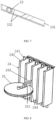
- FIG. 5 is a schematic structural view of the air outlet assembly 100 with the air conditioner air guide pipe 10 being hidden according to an embodiment of the present invention.
- FIG. 6 is a schematic structural view of the air outlet assembly 100 with damper blades 30 and a linkage mechanism 40 being hidden according to an embodiment of the present invention.
- FIG. 7 is a partial enlarged view of part A in FIG. 6 .
- the air outlet main body component 20 further includes two first rotating shafts 22 aligned to the preset axis and two first gears 23.
- the two first rotating shafts 22 are respectively arranged on two sides of the outer surface of the air outlet housing 21.
- Each of the first gears 23 rotatably sleeves each of the first rotating shafts 22.
- FIG. 5 is a schematic structural view of the air outlet assembly 100 with the air conditioner air guide pipe 10 being hidden according to an embodiment of the present invention.
- FIG. 6 is a schematic structural view of the air outlet assembly 100 with damper blades 30 and a linkage mechanism 40 being hidden according to an embodiment of the
- the instrument panel decorative plate 10 is provided with strip-shaped gear holes 101 corresponding to each of the first gears 23, length directions of the strip-shaped gear holes 101 are parallel to the axial direction of the air channel, and at least one inner wall in the length directions of the strip-shaped gear holes 101 is provided with a plurality of first gear teeth 102 meshed with the first gears 23 (with reference to FIG. 7 ). That is, one inner wall in the length directions of the strip-shaped gear holes 101 is provided with the first gear teeth 102 or two inner walls are both provided with the first gear teeth 102. Generally, the first gear teeth 102 are preferably arranged on an inner wall at the downside in the vertical direction of the vehicle. When the two inner walls of the strip-shaped gear holes 101 are both provided with the first gear teeth 102, up-and-down exchange is enabled during assembly, and therefore, the assembling difficulty can be lowered, and rework can be reduced.
- the first gears 23 and the first rotating shafts 22 move together in the length direction of the strip-shaped gear holes 101, and thus, the movement of the air outlet main body component 20 in the axial direction of the air channel is controlled.
- the first rotating shafts 22 rotate along axes thereof (at the moment, the first gears 23 does not rotate with the first rotating shafts 22), thereby driving the air outlet main body component 20 to rotate.
- the above-mentioned force driving the first gears 23 or the first rotating shaft 22 to move may be implemented by arranging a mechanical mechanism such as a long rod with one end being connected to the first gears 23 or the first rotating shafts 22, and the other ends being controlled by a driver.
- a first motor configured to controlling the air outlet main body component 20 to move may also be additionally arranged, the first motor may output a certain displacement and be connected to the first gears 23 or the first rotating shafts 22, and the movement of the first gears 23 or the first rotating shafts 22 is controlled by controlling the starting or stopping of the first motor.
- a moment enabling the first rotating shafts 22 to rotate may also be implemented by arranging a mechanical mechanism or a second motor, and the second motor may output a torque and configured to control the air outlet main body component 20 to rotate.
- FIG. 8 is a schematic assembling view of an integrated lower-layer blade 24 and an impeller 25 of the air outlet assembly 100 according to an embodiment of the present invention.
- the air outlet main body component 20 further includes an integrated lower-layer blade 24 and an impeller 25.
- the integrated lower-layer blade 24 includes a plurality of second rotating shafts 241 and a plurality of blinkers 242 in one-to-one correspondence to each other, the plurality of blinkers 242 are linked, each of the second rotating shafts 241 is configured to rotatably connect the corresponding blinker 242 to the air outlet housing 21, one of the blinkers 242 is fixedly provided with a toggling frame 243, and the toggling frame 243 is provided with a through hole 244 vertically passing through the blinker 242.
- the impeller 25 is rotatably connected to the air outlet housing 21, the axial direction of the impeller 25 is parallel to axial directions of the second rotating shafts 241, the impeller 25 is provided with a gap 251 with an opening facing the integrated lower-layer blade 24, at least parts of the toggling frame 243 extend into the gap 251, and therefore, when the impeller 25 rotates, the toggling frame 243 drives the integrated lower-layer blade 24 to overturn to close or be in communication with the first channel.
- the integrated lower-layer blade 24 and the impeller 25 are arranged in the air outlet housing 21, the impeller 25 may drive the plurality of blinkers 242 of the integrated lower-layer blade 24 to rotate at the same time, and then, a flowing direction of an air flow in the air outlet housing 21 can be changed by different rotation angles of the blinkers 242 under the condition that the first channel is in communication, so that an adjustment direction is increased for the air direction of the air flow flowing through the first channel to better serve for users and meet diversified demands of the users.
- the first rotating shafts 22 are arranged in the transverse direction of the vehicle, and the second rotating shafts 241 are arranged in the vertical direction of the vehicle.
- the axial direction of the air channel is regarded as the longitudinal direction of the vehicle, i.e. a direction directly facing the front of the driver, at the moment, the rotation of the air outlet main body component 20 meets a demand of adjusting an air direction in the vertical direction of the vehicle, and the rotation of the integrated lower-layer blade 24 meets a demand of adjusting an air direction in the horizontal direction of the vehicle.
- the foregoing air outlet main body component 20 may move in the axial direction of the air channel, that is, the air outlet main body component 20 may move in the longitudinal direction of the vehicle, so that the air outlet range of the overall air outlet assembly 100 can meet air outlet demands in all directions of the driver compartment, and the user experience is improved.
- the rotation of the air outlet main body component 20 can meet the air outlet demand of the vehicle in the vertical direction, so that an arrangeable area of the air outlet assembly 100 in a vertical space of the vehicle is larger, and the development of modeling creativity is facilitated.
- the linkage mechanism 40 includes at least one second gear 41, third rotating shafts 42 corresponding to each of the second gears 41, and a gear sheet 43.
- Each of the third rotating shafts 42 is fixed to a rotation center of each of the second gears 41 and is fixedly connected to each of the damper blades 30, wherein axes of the third rotating shafts 42 are parallel to axes of the first rotating shafts 22.
- the gear sheet 43 extends in the axial direction of the air channel, one end of the gear sheet 43 sleeves one of the first rotating shafts 22, and a plurality of second gear teeth 431 meshed with the second gears 41 are arranged in the length direction of the gear sheet 43, so that the air outlet main body component 20 drives each of the damper blades 30 to rotate during movement.
- the gear sheet 43 is sheet-like, and the thickness direction thereof is parallel to the axes of the third rotating shafts 42.
- the number of the second gears 41 is two, and the two second gears 41 are respectively arranged on two sides in the width direction of the gear sheet 43 and are respectively meshed with the second gear teeth 431 opposite thereto.
- the present embodiment shows a specific form of a linkage mechanism 40.
- the first rotating shafts 22 drive the gear sheet 43 to move, thereby driving the second gears 41 meshed with the gear sheet 43 and the third rotating shafts 42 to rotate; and the third rotating shafts 42 rotates to drive the damper blades 30 to overturn, thereby controlling the opening or closing of the first air channel.
- a corresponding relationship between a rotation angle of each of the damper blades 30 and a movement amount of the air outlet main body component 20 may be designed, thereby better meeting an air outlet demand.
- the present invention further provides a vehicle including an air conditioner air guide pipe 200 and at least one air outlet assembly 100 mentioned above.
- the air outlet assembly 100 is provided with one air outlet main body component 20 alone in the air channel in the instrument panel decorative plate 10, and the air outlet main body component 20 is capable of moving and rotating relative to the instrument panel decorative plate 10.
- the position and orientation of the first channel inside the air outlet main body component 20 are changed by controlling the movement and rotation of the air outlet main body component 20, and thus, flowing directions of air flows in the first channel and the second channel and a coverage range of an air flow flowing out of the air outlet assembly 100 are changed.
- the present invention provides a brand new air outlet assembly 100, that is, the air outlet main body component 20 is arranged alone in the instrument panel decorative plate 10, and the air direction and the coverage range of the air flow are adjusted by controlling the movement and rotation of the air outlet main body component 20, so that the coverage range of the air flow is widened, the comfort level of a user is improved, the arrangement position of an air outlet can be selected within a wider range, there are more choices for the modeling creativity of the air outlet, and the development of the modeling creativity is facilitated.
Landscapes
- Physics & Mathematics (AREA)
- Thermal Sciences (AREA)
- Engineering & Computer Science (AREA)
- Mechanical Engineering (AREA)
- Air-Flow Control Members (AREA)
- Air-Conditioning For Vehicles (AREA)
Abstract
Description
- The present invention relates to the field of vehicles, in particular to an air outlet assembly, and a vehicle.
- At present, an air outlet of a traditional car has mainly guided air by virtue of an air outlet blade, and an air outlet assembly has been fixed to an instrument desk or an auxiliary instrument desk so as to be incapable of rotating. For the need of human-machine comfort, an air flow at an air outlet has to be upwards blown over the head and downwards blown to the waist. Due to such a demand, the arrangement position of the outlet is limited, and facilitate the development of modeling creativity is also limited by the exposed blade.
- In view of the above-mentioned problems, the present invention is proposed to provide an air outlet assembly overcoming the above-mentioned problems or at least partially solving the above-mentioned problems, and a vehicle.
- One objective of a first aspect of the present invention is to provide a novel air outlet assembly capable of reducing the limitations on the arrangement position of an outlet, and facilitating the development of modeling creativity.
- The other objective of the present invention is to widen a coverage range of an air flow at an air outlet.
- One objective of a second aspect of the present invention is to provide a vehicle including the above-mentioned air outlet assembly. The vehicle is little in limitations on the arrangement position of an outlet, and facilitates the development of modeling creativity.
- Particularly, one aspect of an embodiment of the present invention provides an air outlet assembly, including:
- an instrument panel decorative plate, an air channel which is in communication with an air conditioner air guide pipe of a vehicle being arranged at the inside of the instrument panel decorative plate, and an opening at the end, away from the air conditioner air guide pipe, of the air channel facing a driver compartment; and
- an air outlet main body component arranged in the air channel, a first channel which is capable of being opened and closed being arranged in the air outlet main body component, a second channel being formed by an outer surface of the air outlet main body component and an inner wall face of the air channel, the air outlet main body component being configured to be controlled to move in the axial direction of the air channel and rotate around a preset axis, and the preset axis being parallel to a vertical plane in the axial direction of the air channel.
- Optionally, the end, close to the driver compartment, of the air channel is configured to gradually expand in a direction pointing to the driver compartment, and an appearance of the end, close to the driver compartment, of the air outlet main body component is configured to gradually shrink in the direction pointing to the driver compartment, so that an expansion opening is formed in the end, close to the driver compartment, of the second channel.
- Optionally, the air outlet assembly further includes:
- at least one damper blade rotatably connected to the inside of the air channel and configured to be in communication with or block the air channel; and
- a linkage mechanism configured to connect the at least one damper blade and the air outlet main body component, so that the air outlet main body component drives the at least one damper blade to rotate during movement.
- Optionally, the at least one damper blade is configured to block the air channel when the air outlet main body component is located on an initial position and to be in gradual communication with the air channel when the air outlet main body component moves from the initial position to the driver compartment.
- Optionally, the at least one damper blade is further configured to be in communication with the air channel to the greatest extent when the air outlet main body component moves to be partially exposed out of the instrument panel decorative plate.
- Optionally, the air outlet main body component includes:
an air outlet housing in which the first channel is formed, the second channel being formed by an outer surface of the air outlet housing and the inner wall face of the air channel. - Optionally, a plurality of air outlet nozzles configured to partition an air flow inside the first channel into a plurality of paths of air flows are formed on the end, close to the driver compartment, of the air outlet housing.
- Optionally, each of the air outlet nozzles is configured to gradually shrink in the direction pointing to the driver compartment.
- Optionally, the air outlet main body component further includes:
- two first rotating shafts aligned to the preset axis and respectively arranged on two sides of the outer surface of the air outlet housing; and
- two first gears, each of the first gears rotatably sleeving each of the first rotating shafts;
- the instrument panel decorative plate being provided with strip-shaped gear holes corresponding to each of the first gears, length directions of the strip-shaped gear holes being parallel to the axial direction of the air channel, and at least one inner wall in the length directions of the strip-shaped gear holes being provided with a plurality of first gear teeth meshed with the first gears.
- Optionally, the air outlet main body component further includes:
- an integrated lower-layer blade including a plurality of second rotating shafts and a plurality of blinkers in one-to-one correspondence to each other, the plurality of blinkers being linked, each of the second rotating shafts being configured to rotatably connect the corresponding blinker to the air outlet housing, one of the blinkers being fixedly provided with a toggling frame, and the toggling frame being provided with a through hole vertically passing through the blinker; and
- an impeller rotatably connected to the air outlet housing, the axial direction of the impeller being parallel to axial directions of the second rotating shafts, the impeller being provided with a gap with an opening facing the integrated lower-layer blade, at least parts of the toggling frame extending into the gap, and therefore, when the impeller rotates, the toggling frame drives the integrated lower-layer blade to overturn to close or be in communication with the first channel and adjust a direction of an air flow flowing through the first channel under the condition that the first channel is in communication.
- Optionally, the first rotating shafts are arranged in the transverse direction of the vehicle, and the second rotating shafts are arranged in the vertical direction of the vehicle.
- Optionally, the linkage mechanism includes:
- at least one second gear;
- third rotating shafts corresponding to each of the second gears, each of the third rotating shafts being fixed to a rotation center of each of the second gears and being fixedly connected to each of the damper blades, wherein axes of the third rotating shafts are parallel to axes of the first rotating shafts; and
- a gear sheet extending in the axial direction of the air channel, one end of the gear sheet sleeving one of the first rotating shafts, and a plurality of second gear teeth meshed with the second gears being arranged in the length direction of the gear sheet, so that the air outlet main body component drives each of the damper blades to rotate during movement.
- Optionally, the gear sheet is sheet-like, and the thickness direction thereof is parallel to the axes of the third rotating shafts; and
the number of the second gears is two, and the two second gears are respectively arranged on two sides in the width direction of the gear sheet and are respectively meshed with the second gear teeth opposite thereto. - Optionally, the air outlet assembly further includes:
- a first motor configured to control the air outlet main body component to move; and
- a second motor configured to control the air outlet main body component to rotate.
- Particularly, the other aspect of an embodiment of the present invention provides a vehicle, including an air conditioner air guide pipe and any one air outlet assembly mentioned above.
- According to the present invention, one air outlet main body component is arranged alone in the air channel in the instrument panel decorative plate, and the air outlet main body component is capable of moving and rotating relative to the instrument panel decorative plate. The position and orientation of the first channel inside the air outlet main body component are changed by controlling the movement and rotation of the air outlet main body component, and thus, flowing directions of air flows in the first channel and the second channel and a coverage range of an air flow flowing out of the air outlet assembly are changed. Compared with an existing structure that an air outlet blade is directly connected to the instrument panel decorative plate and an air direction is adjusted by changing an angle of the air outlet blade, the present invention provides a brand new air outlet assembly, that is, the air outlet main body component is arranged alone in the instrument panel decorative plate, and the air direction and the coverage range of the air flow are adjusted by controlling the movement and rotation of the air outlet main body component, so that the coverage range of the air flow is widened, the comfort level of a user is improved, the arrangement position of an air outlet can be selected within a wider range, there are more choices for the modeling creativity of the air outlet, and the development of the modeling creativity is facilitated.
- Further, an appearance of a front end of the air outlet main body component (which is specifically the air outlet housing of the air outlet main body component) gradually shrinks in a direction pointing to the driver compartment, and the end, close to the driver compartment, of the air channel at the inside of the instrument panel decorative plate gradually expands in the direction pointing to the driver compartment, so that an expansion opening is formed in the end, close to the driver compartment, of the second channel formed between the air outlet housing and the instrument panel decorative plate, and then, the coverage range of the air flow is widened. Moreover, in the present invention, the air flow is jointly guided by the modeling of the instrument panel decorative plate and the appearance of the air outlet main body component, the traditional blade modeling is abandoned, and the selectivity of the modeling creativity of the air outlet is further enriched.
- Further, a plurality of air outlet nozzles configured to partition an air flow inside the first channel into a plurality of paths of air flows are formed on the end, close to the driver compartment, of the air outlet housing. The plurality of air outlet nozzles formed on the air outlet housing can effectively disperse the air flow into a plurality of air paths to increase the flow velocity of the air flow here, so that warm air or cold air rapidly and centrally blows to the driver compartment, and the user experience is improved.
- Further, the air outlet nozzles are all configured to gradually shrink in the direction pointing to the driver compartment, in this way, the cross section of an air flow channel can be further reduced, the air flow can be better centralized, and the flow velocity can be increased.
- The above-mentioned description is merely a summary of the technical solutions of the present invention. In order to more clearly know about the technical means of the present invention, they may be implemented according to the content of the description. Moreover, in order to make the above-mentioned and other objectives, features, and advantages of the present disclosure more obvious and comprehensible, the specific implementations of the present invention will be listed below.
- According to the following detailed description of the specific embodiments of the present invention in combination with accompanying drawings, the skilled in the art will better know about the above-mentioned and other objectives, advantages and characteristics of the present invention.
- Hereinafter, some specific embodiments of the present invention will be described in detail with reference to accompanying drawings in an exemplary way instead of a restrictive way. The same reference numerals in the accompanying drawings indicate the same or similar components or parts. It should be understood by the skilled in the art that these accompanying drawings are not necessarily drawn according to a proportion. In the accompanying drawings:
-
FIG. 1 is a cross-sectional view of an air outlet assembly and an air conditioner air guide pipe according to an embodiment of the present invention; -
FIG. 2 is a cross-sectional view shown when an air outlet main body component of the air outlet assembly rotates to a first angle according to an embodiment of the present invention; -
FIG. 3 is a cross-sectional view shown when the air outlet main body component of the air outlet assembly rotates to a second angle according to an embodiment of the present invention; -
FIG. 4 is a schematic structural view of the air outlet assembly and the air conditioner air guide pipe according to an embodiment of the present invention; -
FIG. 5 is a schematic structural view of the air outlet assembly with the air conditioner air guide pipe being hidden according to an embodiment of the present invention; -
FIG. 6 is a schematic structural view of the air outlet assembly with damper blades and a linkage mechanism being hidden according to an embodiment of the present invention; -
FIG. 7 is a partial enlarged view of part A inFIG. 6 ; and -
FIG. 8 is a schematic assembling view of an integrated lower-layer blade and an impeller of the air outlet assembly according to an embodiment of the present invention. - Exemplary embodiments in the present disclosure will be described in more detail below with reference to the accompanying drawings. Although the exemplary embodiments in the present disclosure are shown in the accompanying drawings, it should be understood that the present disclosure can be implemented in various forms, but should not be limited by the embodiments described herein. On the contrary, these embodiments are provided for understanding the present disclosure more thoroughly and integrally transmitting the scope of the present disclosure to the skilled in the art.
-
FIG. 1 is a cross-sectional view of anair outlet assembly 100 and an air conditionerair guide pipe 200 according to an embodiment of the present invention.FIG. 2 is a cross-sectional view shown when an air outletmain body component 20 of theair outlet assembly 100 rotates to a first angle according to an embodiment of the present invention.FIG. 3 is a cross-sectional view shown when the air outletmain body component 20 of theair outlet assembly 100 rotates to a second angle according to an embodiment of the present invention. Arrows inFIG. 1 to FIG. 3 represent a trend of an air flow. As shown inFIG. 1 , in an embodiment, theair outlet assembly 100 in the present invention includes an instrument paneldecorative plate 10 and the air outletmain body component 20. An air channel which is in communication with the air conditionerair guide pipe 200 of a vehicle is arranged at the inside of the instrument paneldecorative plate 10, and an opening at the end, away from the air conditionerair guide pipe 200, of the air channel faces a driver compartment. The air outletmain body component 20 is arranged in the air channel. A first channel which is capable of being opened and closed is arranged in the air outletmain body component 20, a second channel is formed by an outer surface of the air outletmain body component 20 and an inner wall face of the air channel, and the air outletmain body component 20 is configured to be controlled to move in the axial direction of the air channel and rotate around a preset axis (as shown inFIG. 2 andFIG. 3 ). The preset axis is parallel to a vertical plane in the axial direction of the air channel. Herein, the shape of the air outletmain body component 20 can be adaptively designed according to the shape of the air channel, for example, when the air channel is a square channel, the air outletmain body component 20 can also be set to be of an approximately square shape, and when the air channel is shaped like a circular pipe, the air outletmain body component 20 can also be set to have a circular cross section. - As shown in
FIG. 1 , the air outletmain body component 20 in this position state makes an air flow basically blown out in the axial direction of the air channel. The air outletmain body component 20 inFIG. 2 upwarps so that the air flow is obliquely and upwards blown out from the second channel and the first channel which are located above the air outletmain body component 20. The air outletmain body component 20 inFIG. 3 is downwards inclined so that the air flow is obliquely and downwards blown out from the second channel and the first channel which are located below the air outletmain body component 20. In addition, the air outletmain body component 20 moves forwards and backwards so that theair outlet assembly 100 can cover an air flow direction within a wider range. - In the present embodiment, one air outlet
main body component 20 is arranged alone in the air channel in the instrument paneldecorative plate 10, and the air outletmain body component 20 is capable of moving and rotating relative to the instrument paneldecorative plate 10. The position and orientation of the first channel inside the air outletmain body component 20 are changed by controlling the movement and rotation of the air outletmain body component 20, and thus, flowing directions of air flows in the first channel and the second channel and a coverage range of an air flow flowing out of theair outlet assembly 100 are changed. Compared with an existing structure that an air outlet blade is directly connected to the instrument paneldecorative plate 10 and an air direction is adjusted by changing an angle of the air outlet blade, the present invention provides a brand newair outlet assembly 100, that is, the air outletmain body component 20 is arranged alone in the instrument paneldecorative plate 10, and the air direction and the coverage range of the air flow are adjusted by controlling the movement and rotation of the air outletmain body component 20, so that the coverage range of the air flow is widened, the comfort level of a user is improved, the arrangement position of an air outlet can be selected within a wider range, there are more choices for the modeling creativity of the air outlet, and the development of the modeling creativity is facilitated. - As shown in
FIG. 1 , in a further embodiment, the end, close to the driver compartment, of the air channel is configured to gradually expand in a direction pointing to the driver compartment, and an appearance of the end, close to the driver compartment, of the air outletmain body component 20 is configured to gradually shrink in the direction pointing to the driver compartment, so that an expansion opening is formed in the end, close to the driver compartment, of the second channel. - Herein, it is equivalent to arrangement of a flanging for guidance at the end, close to the driver compartment, of the instrument panel
decorative plate 10. A space is left between the air outletmain body component 20 and the instrument paneldecorative plate 10 to enable the air flow to flow along a surface of the flanging, so that an area covered by the air flow is further expanded. In the present embodiment, the air flow is jointly guided by the modeling of the instrument paneldecorative plate 10 and the appearance of the air outletmain body component 20, the traditional blade modeling is abandoned, and the selectivity of the modeling creativity of the air outlet is further enriched. -
FIG. 4 is a schematic structural view of theair outlet assembly 100 and the air conditionerair guide pipe 200 according to an embodiment of the present invention. Theair outlet assembly 100 further includes at least onedamper blade 30 rotatably connected to the inside of the air channel (with reference toFIG. 1 ) and configured to be in communication with or block the air channel. In another embodiment, theair outlet assembly 100 further includes alinkage mechanism 40 configured to connect the at least onedamper blade 30 and the air outletmain body component 20, so that the air outletmain body component 20 drives the at least onedamper blade 30 to rotate during movement. Optionally, the at least onedamper blade 30 is configured to block the air channel when the air outletmain body component 20 is located on an initial position and to be in gradual communication with the air channel when the air outletmain body component 20 moves from the initial position to the driver compartment. It can be imagined that the air channel can be completely closed when thedamper blades 30 rotate for 90° clockwise or counterclockwise from a state inFIG. 1 . Due to the arrangement of thelinkage mechanism 40, the movement of the air outletmain body component 20 may drive the rotation of thedamper blades 30, and then, the flow rate of the air flow is distributed, that is, the amount and angle of the air flow flowing out of thedamper blades 30 are controlled. - Of course, the
damper blades 30 may also be rotatably connected to the air conditionerair guide pipe 200 to control the blockage or communication of the air channel inside the air conditionerair guide pipe 200. In the present embodiment, thedamper blades 30 are arranged in the air channel of the instrument paneldecorative plate 10 to conveniently form an assembly with theair outlet assembly 100, thereby facilitating assembly. - In a further embodiment, the at least one
damper blade 30 is further configured to be in communication with the air channel to the greatest extent when the air outletmain body component 20 moves to be partially exposed out of the instrument panel decorative plate 10 (with reference toFIG. 4 ), at the moment, states of thedamper blades 30 are shown inFIG. 1 . Of course, in other embodiments, the position of the air outletmain body component 20 and the states of thedamper blades 30 can also be correspondingly set, for example, thedamper blades 30 are completely opened when the front end of the air outletmain body component 20 is flushed with the instrument paneldecorative plate 10. During applications to a specific vehicle, the position of the air outletmain body component 20 and the states of thedamper blades 30 of theair outlet assembly 100 on a different position can also be designed to be the same or different, and thus, the comfort level is improved. - As shown in
FIG. 1 , in the present embodiment, the air outletmain body component 20 includes anair outlet housing 21 in which the first channel is formed, the second channel is formed by an outer surface of theair outlet housing 21 and the inner wall face of the air channel. It can be seen fromFIG. 1 that an appearance of a front end of theair outlet housing 21 gradually shrinks in a direction pointing to the driver compartment, and the end, close to the driver compartment, of the air channel at the inside of the instrument paneldecorative plate 10 gradually expands in the direction pointing to the driver compartment, so that an expansion opening is formed in the end, close to the driver compartment, of the second channel formed between theair outlet housing 21 and the instrument paneldecorative plate 10, and then, the coverage range of the air flow is widened. - In a further embodiment, as shown in
FIG. 1 , a plurality ofair outlet nozzles 211 configured to partition an air flow inside the first channel into a plurality of paths of air flows are formed on the end, close to the driver compartment, of theair outlet housing 21. The plurality ofair outlet nozzles 211 formed on theair outlet housing 21 can effectively disperse the air flow into a plurality of air paths to increase the flow velocity of the air flow here, so that warm air or cold air rapidly and centrally blows to the driver compartment, and the user experience is improved. - Optionally, the
air outlet nozzles 211 are all configured to gradually shrink in the direction pointing to the driver compartment, in this way, the cross section of an air flow channel can be further reduced, the air flow can be better centralized, and the flow velocity can be increased. -
FIG. 5 is a schematic structural view of theair outlet assembly 100 with the air conditionerair guide pipe 10 being hidden according to an embodiment of the present invention.FIG. 6 is a schematic structural view of theair outlet assembly 100 withdamper blades 30 and alinkage mechanism 40 being hidden according to an embodiment of the present invention.FIG. 7 is a partial enlarged view of part A inFIG. 6 . In an embodiment, as shown inFIG. 5 , the air outletmain body component 20 further includes two firstrotating shafts 22 aligned to the preset axis and twofirst gears 23. The two firstrotating shafts 22 are respectively arranged on two sides of the outer surface of theair outlet housing 21. Each of thefirst gears 23 rotatably sleeves each of the firstrotating shafts 22. As shown inFIG. 6 , the instrument paneldecorative plate 10 is provided with strip-shaped gear holes 101 corresponding to each of thefirst gears 23, length directions of the strip-shaped gear holes 101 are parallel to the axial direction of the air channel, and at least one inner wall in the length directions of the strip-shaped gear holes 101 is provided with a plurality offirst gear teeth 102 meshed with the first gears 23 (with reference toFIG. 7 ). That is, one inner wall in the length directions of the strip-shaped gear holes 101 is provided with thefirst gear teeth 102 or two inner walls are both provided with thefirst gear teeth 102. Generally, thefirst gear teeth 102 are preferably arranged on an inner wall at the downside in the vertical direction of the vehicle. When the two inner walls of the strip-shaped gear holes 101 are both provided with thefirst gear teeth 102, up-and-down exchange is enabled during assembly, and therefore, the assembling difficulty can be lowered, and rework can be reduced. - When a force in the axial direction of the air channel is applied to the
first gears 23 or the firstrotating shafts 22, thefirst gears 23 and the firstrotating shafts 22 move together in the length direction of the strip-shaped gear holes 101, and thus, the movement of the air outletmain body component 20 in the axial direction of the air channel is controlled. By applying a torque to the firstrotating shafts 22, the firstrotating shafts 22 rotate along axes thereof (at the moment, thefirst gears 23 does not rotate with the first rotating shafts 22), thereby driving the air outletmain body component 20 to rotate. - Optionally, the above-mentioned force driving the
first gears 23 or the firstrotating shaft 22 to move may be implemented by arranging a mechanical mechanism such as a long rod with one end being connected to thefirst gears 23 or the firstrotating shafts 22, and the other ends being controlled by a driver. For example, corresponding keys are arranged in the driver compartment to control the other end of the long rod, thereby pushing thefirst gears 23 or the firstrotating shafts 22. Of course, a first motor configured to controlling the air outletmain body component 20 to move may also be additionally arranged, the first motor may output a certain displacement and be connected to thefirst gears 23 or the firstrotating shafts 22, and the movement of thefirst gears 23 or the firstrotating shafts 22 is controlled by controlling the starting or stopping of the first motor. Similarly, a moment enabling the firstrotating shafts 22 to rotate may also be implemented by arranging a mechanical mechanism or a second motor, and the second motor may output a torque and configured to control the air outletmain body component 20 to rotate. -
FIG. 8 is a schematic assembling view of an integrated lower-layer blade 24 and animpeller 25 of theair outlet assembly 100 according to an embodiment of the present invention. As shown inFIG. 8 , in the present embodiment, the air outletmain body component 20 further includes an integrated lower-layer blade 24 and animpeller 25. The integrated lower-layer blade 24 includes a plurality of secondrotating shafts 241 and a plurality ofblinkers 242 in one-to-one correspondence to each other, the plurality ofblinkers 242 are linked, each of the secondrotating shafts 241 is configured to rotatably connect thecorresponding blinker 242 to theair outlet housing 21, one of theblinkers 242 is fixedly provided with atoggling frame 243, and thetoggling frame 243 is provided with a throughhole 244 vertically passing through theblinker 242. Theimpeller 25 is rotatably connected to theair outlet housing 21, the axial direction of theimpeller 25 is parallel to axial directions of the secondrotating shafts 241, theimpeller 25 is provided with agap 251 with an opening facing the integrated lower-layer blade 24, at least parts of the togglingframe 243 extend into thegap 251, and therefore, when theimpeller 25 rotates, the togglingframe 243 drives the integrated lower-layer blade 24 to overturn to close or be in communication with the first channel. - Moreover, in the present embodiment, the integrated lower-
layer blade 24 and theimpeller 25 are arranged in theair outlet housing 21, theimpeller 25 may drive the plurality ofblinkers 242 of the integrated lower-layer blade 24 to rotate at the same time, and then, a flowing direction of an air flow in theair outlet housing 21 can be changed by different rotation angles of theblinkers 242 under the condition that the first channel is in communication, so that an adjustment direction is increased for the air direction of the air flow flowing through the first channel to better serve for users and meet diversified demands of the users. - In an embodiment, the first
rotating shafts 22 are arranged in the transverse direction of the vehicle, and the secondrotating shafts 241 are arranged in the vertical direction of the vehicle. At the moment, the axial direction of the air channel is regarded as the longitudinal direction of the vehicle, i.e. a direction directly facing the front of the driver, at the moment, the rotation of the air outletmain body component 20 meets a demand of adjusting an air direction in the vertical direction of the vehicle, and the rotation of the integrated lower-layer blade 24 meets a demand of adjusting an air direction in the horizontal direction of the vehicle. In addition, the foregoing air outletmain body component 20 may move in the axial direction of the air channel, that is, the air outletmain body component 20 may move in the longitudinal direction of the vehicle, so that the air outlet range of the overallair outlet assembly 100 can meet air outlet demands in all directions of the driver compartment, and the user experience is improved. - Further, the rotation of the air outlet
main body component 20 can meet the air outlet demand of the vehicle in the vertical direction, so that an arrangeable area of theair outlet assembly 100 in a vertical space of the vehicle is larger, and the development of modeling creativity is facilitated. - As shown in
FIG. 5 , thelinkage mechanism 40 includes at least onesecond gear 41, thirdrotating shafts 42 corresponding to each of thesecond gears 41, and agear sheet 43. Each of the thirdrotating shafts 42 is fixed to a rotation center of each of thesecond gears 41 and is fixedly connected to each of thedamper blades 30, wherein axes of the thirdrotating shafts 42 are parallel to axes of the firstrotating shafts 22. Thegear sheet 43 extends in the axial direction of the air channel, one end of thegear sheet 43 sleeves one of the firstrotating shafts 22, and a plurality ofsecond gear teeth 431 meshed with thesecond gears 41 are arranged in the length direction of thegear sheet 43, so that the air outletmain body component 20 drives each of thedamper blades 30 to rotate during movement. In a further embodiment, as shown inFIG. 5 , thegear sheet 43 is sheet-like, and the thickness direction thereof is parallel to the axes of the thirdrotating shafts 42. The number of thesecond gears 41 is two, and the twosecond gears 41 are respectively arranged on two sides in the width direction of thegear sheet 43 and are respectively meshed with thesecond gear teeth 431 opposite thereto. - The present embodiment shows a specific form of a
linkage mechanism 40. When theair outlet housing 21 starts to move under the action of an external force, the firstrotating shafts 22 drive thegear sheet 43 to move, thereby driving thesecond gears 41 meshed with thegear sheet 43 and the thirdrotating shafts 42 to rotate; and the thirdrotating shafts 42 rotates to drive thedamper blades 30 to overturn, thereby controlling the opening or closing of the first air channel. As shown above, a corresponding relationship between a rotation angle of each of thedamper blades 30 and a movement amount of the air outletmain body component 20 may be designed, thereby better meeting an air outlet demand. - The present invention further provides a vehicle including an air conditioner
air guide pipe 200 and at least oneair outlet assembly 100 mentioned above. - The
air outlet assembly 100 is provided with one air outletmain body component 20 alone in the air channel in the instrument paneldecorative plate 10, and the air outletmain body component 20 is capable of moving and rotating relative to the instrument paneldecorative plate 10. The position and orientation of the first channel inside the air outletmain body component 20 are changed by controlling the movement and rotation of the air outletmain body component 20, and thus, flowing directions of air flows in the first channel and the second channel and a coverage range of an air flow flowing out of theair outlet assembly 100 are changed. Compared with an existing structure that an air outlet blade is directly connected to the instrument paneldecorative plate 10 and an air direction is adjusted by changing an angle of the air outlet blade, the present invention provides a brand newair outlet assembly 100, that is, the air outletmain body component 20 is arranged alone in the instrument paneldecorative plate 10, and the air direction and the coverage range of the air flow are adjusted by controlling the movement and rotation of the air outletmain body component 20, so that the coverage range of the air flow is widened, the comfort level of a user is improved, the arrangement position of an air outlet can be selected within a wider range, there are more choices for the modeling creativity of the air outlet, and the development of the modeling creativity is facilitated. - So far, those skilled in the art should recognize that the exemplarily embodiments of the present invention have been shown and described in detail herein, however, many other variations or modifications conforming to the principle of the present invention can be directly determined or deduced according to the contents of the present invention without departing from the spirit and scope of the present invention. Therefore, the scope of the present invention should be understood and regarded to cover all other variations or modifications.
Claims (15)
- An air outlet assembly, characterized by comprising:an instrument panel decorative plate, an air channel which is in communication with an air conditioner air guide pipe of a vehicle being arranged at the inside of the instrument panel decorative plate, and an opening at the end, away from the air conditioner air guide pipe, of the air channel facing a driver compartment; andan air outlet main body component arranged in the air channel, a first channel which is capable of being opened and closed being arranged in the air outlet main body component, a second channel being formed by an outer surface of the air outlet main body component and an inner wall face of the air channel, the air outlet main body component being configured to be controlled to move in the axial direction of the air channel and rotate around a preset axis, and the preset axis being parallel to a vertical plane in the axial direction of the air channel.
- The air outlet assembly according to claim 1, characterized in that
the end, close to the driver compartment, of the air channel is configured to gradually expand in a direction pointing to the driver compartment, and an appearance of the end, close to the driver compartment, of the air outlet main body component is configured to gradually shrink in the direction pointing to the driver compartment, so that an expansion opening is formed in the end, close to the driver compartment, of the second channel. - The air outlet assembly according to claim 1, characterized by further comprising:at least one damper blade rotatably connected to the inside of the air channel and configured to be in communication with or block the air channel; anda linkage mechanism configured to connect the at least one damper blade and the air outlet main body component, so that the air outlet main body component drives the at least one damper blade to rotate during movement.
- The air outlet assembly according to claim 3, characterized in that
the at least one damper blade is configured to block the air channel when the air outlet main body component is located on an initial position and to be in gradual communication with the air channel when the air outlet main body component moves from the initial position to the driver compartment. - The air outlet assembly according to claim 4, characterized in that
the at least one damper blade is further configured to be in communication with the air channel to the greatest extent when the air outlet main body component moves to be partially exposed out of the instrument panel decorative plate. - The air outlet assembly according to any one of claims 3 to 5, characterized in that the air outlet main body component comprises:
an air outlet housing in which the first channel is formed, the second channel being formed by an outer surface of the air outlet housing and the inner wall face of the air channel. - The air outlet assembly according to claim 6, characterized in that
a plurality of air outlet nozzles configured to partition an air flow inside the first channel into a plurality of paths of air flows are formed on the end, close to the driver compartment, of the air outlet housing. - The air outlet assembly according to claim 7, characterized in that
each of the air outlet nozzles is configured to gradually shrink in the direction pointing to the driver compartment. - The air outlet assembly according to claim 6, characterized in that the air outlet main body component further comprises:two first rotating shafts aligned to the preset axis and respectively arranged on two sides of the outer surface of the air outlet housing; andtwo first gears, each of the first gears rotatably sleeving each of the first rotating shafts;the instrument panel decorative plate being provided with strip-shaped gear holes corresponding to each of the first gears, length directions of the strip-shaped gear holes being parallel to the axial direction of the air channel, and at least one inner wall in the length directions of the strip-shaped gear holes being provided with a plurality of first gear teeth meshed with the first gears.
- The air outlet assembly according to claim 9, characterized in that the air outlet main body component further comprises:an integrated lower-layer blade comprising a plurality of second rotating shafts and a plurality of blinkers in one-to-one correspondence to each other, the plurality of blinkers being linked, each of the second rotating shafts being configured to rotatably connect the corresponding blinker to the air outlet housing, one of the blinkers being fixedly provided with a toggling frame, and the toggling frame being provided with a through hole vertically passing through the blinker; andan impeller rotatably connected to the air outlet housing, the axial direction of the impeller being parallel to axial directions of the second rotating shafts, the impeller being provided with a gap with an opening facing the integrated lower-layer blade, at least parts of the toggling frame extending into the gap, and therefore, when the impeller rotates, the toggling frame drives the integrated lower-layer blade to overturn to close or be in communication with the first channel and adjust a direction of an air flow flowing through the first channel under the condition that the first channel is in communication.
- The air outlet assembly according to claim 10, characterized in that
the first rotating shafts are arranged in the transverse direction of the vehicle, and the second rotating shafts are arranged in the vertical direction of the vehicle. - The air outlet assembly according to claim 9, characterized in that the linkage mechanism comprises:at least one second gear;third rotating shafts corresponding to each of the second gears, each of the third rotating shafts being fixed to a rotation center of each of the second gears and being fixedly connected to each of the damper blades, wherein axes of the third rotating shafts are parallel to axes of the first rotating shafts; anda gear sheet extending in the axial direction of the air channel, one end of the gear sheet sleeving one of the first rotating shafts, and a plurality of second gear teeth meshed with the second gears being arranged in the length direction of the gear sheet, so that the air outlet main body component drives each of the damper blades to rotate during movement.
- The air outlet assembly according to claim 12, characterized in thatthe gear sheet is sheet-like, and the thickness direction thereof is parallel to the axes of the third rotating shafts; andthe number of the second gears is two, and the two second gears are respectively arranged on two sides in the width direction of the gear sheet and are respectively meshed with the second gear teeth opposite thereto.
- The air outlet assembly according to claim 1, characterized by further comprising:a first motor configured to control the air outlet main body component to move; anda second motor configured to control the air outlet main body component to rotate.
- A vehicle, characterized by comprising an air conditioner air guide pipe and at least one air outlet assembly according to any one of claims 1 to 14.
Applications Claiming Priority (1)
| Application Number | Priority Date | Filing Date | Title |
|---|---|---|---|
| PCT/CN2021/071436 WO2022151027A1 (en) | 2021-01-13 | 2021-01-13 | Air outlet assembly, and vehicle |
Publications (3)
| Publication Number | Publication Date |
|---|---|
| EP4279302A1 true EP4279302A1 (en) | 2023-11-22 |
| EP4279302A4 EP4279302A4 (en) | 2024-11-13 |
| EP4279302B1 EP4279302B1 (en) | 2026-04-22 |
Family
ID=82446849
Family Applications (1)
| Application Number | Title | Priority Date | Filing Date |
|---|---|---|---|
| EP21918243.3A Active EP4279302B1 (en) | 2021-01-13 | 2021-01-13 | Vehicle comprising an air outlet assembly |
Country Status (3)
| Country | Link |
|---|---|
| EP (1) | EP4279302B1 (en) |
| CN (1) | CN116568538A (en) |
| WO (1) | WO2022151027A1 (en) |
Families Citing this family (4)
| Publication number | Priority date | Publication date | Assignee | Title |
|---|---|---|---|---|
| CN115199595B (en) * | 2022-07-25 | 2025-01-03 | 中国华能集团清洁能源技术研究院有限公司 | Steam pressure matcher |
| CN115122877B (en) * | 2022-08-31 | 2022-12-02 | 宁波均胜群英汽车系统股份有限公司 | Air outlet with switchable air outlet direction |
| CN115195412B (en) * | 2022-09-16 | 2022-12-23 | 宁波均胜群英汽车系统股份有限公司 | Blowing method of hidden air conditioner air outlet |
| CN119567821B (en) * | 2025-01-13 | 2026-01-20 | 深蓝汽车科技有限公司 | A concealed air vent assembly and vehicle |
Family Cites Families (11)
| Publication number | Priority date | Publication date | Assignee | Title |
|---|---|---|---|---|
| JPH08197940A (en) * | 1995-01-30 | 1996-08-06 | Nippon Plast Co Ltd | Wind direction adjusting device |
| FR2886383B1 (en) * | 2005-05-26 | 2007-09-21 | Faurecia Interieur Ind Snc | AERATOR WITH ADJUSTMENT OF ORIENTATION AND FLOW AND CENTRAL AIR PASSAGE |
| DE202008008872U1 (en) * | 2008-10-13 | 2008-12-24 | Dr. Schneider Kunststoffwerke Gmbh | air nozzle |
| JP6361221B2 (en) * | 2014-03-27 | 2018-07-25 | 株式会社デンソー | Air blowing device |
| JP6260543B2 (en) * | 2015-01-13 | 2018-01-17 | トヨタ自動車株式会社 | register |
| DE102018211375A1 (en) * | 2018-07-10 | 2020-01-16 | Faurecia Automotive Industrie | Air outlet for directing an air flow in different directions into a vehicle interior |
| CN109501556A (en) * | 2018-12-28 | 2019-03-22 | 依工(宁波)电子元件紧固装置有限公司 | A kind of concealed calm sense automotive air outlet |
| DE212020000484U1 (en) * | 2019-01-07 | 2021-07-09 | Product Development Engineernanjing Tata Autocomp Systems Limited | Air outlet mechanism without front blades |
| EP3736149A1 (en) * | 2019-05-06 | 2020-11-11 | NIO (Anhui) Holding Co., Ltd. | Air duct assembly |
| CN210436971U (en) * | 2019-09-06 | 2020-05-01 | 上海延锋金桥汽车饰件系统有限公司 | Air outlet structure |
| CN111016585A (en) * | 2019-12-24 | 2020-04-17 | 宁波东昊汽车部件有限公司 | A car invisible air outlet |
-
2021
- 2021-01-13 WO PCT/CN2021/071436 patent/WO2022151027A1/en not_active Ceased
- 2021-01-13 EP EP21918243.3A patent/EP4279302B1/en active Active
- 2021-01-13 CN CN202180054095.3A patent/CN116568538A/en active Pending
Also Published As
| Publication number | Publication date |
|---|---|
| EP4279302A4 (en) | 2024-11-13 |
| EP4279302B1 (en) | 2026-04-22 |
| WO2022151027A1 (en) | 2022-07-21 |
| CN116568538A (en) | 2023-08-08 |
Similar Documents
| Publication | Publication Date | Title |
|---|---|---|
| EP4279302B1 (en) | Vehicle comprising an air outlet assembly | |
| CN111559226B (en) | Automobile air outlet structure | |
| JP5614963B2 (en) | Driving force transmission mechanism | |
| KR102120773B1 (en) | air vent for car | |
| KR101526808B1 (en) | An air vent for a vehicle | |
| CN102162674A (en) | Sliding door device | |
| JP2008543664A (en) | Air blowing nozzle | |
| JP2014234936A (en) | Air blower | |
| CN113580887B (en) | Air outlet device and air outlet system in car | |
| CN112046250B (en) | Hidden air conditioner air outlet, air conditioning equipment, motor vehicle and air guiding method | |
| EP3372428B1 (en) | Internal air vent for vehicles | |
| CN114013249B (en) | Vehicle air conditioning outlet regulating device | |
| JP5009807B2 (en) | Air conditioner for automobile | |
| JP2003025835A (en) | Air blowdown device | |
| CN215260455U (en) | Air guide member and air conditioner having the same | |
| CN115056633A (en) | Air-conditioning air outlet assembly and vehicle | |
| JP2019069727A (en) | Vehicular air conditioner | |
| CN216443443U (en) | A vehicle air conditioner air outlet adjustment device | |
| JP6423996B2 (en) | Air outlet device | |
| CN216443442U (en) | Manual adjustment device for air outlet of vehicle air conditioner | |
| JPH08197940A (en) | Wind direction adjusting device | |
| CN115479386B (en) | Air guide part and air conditioner with same | |
| CN216346613U (en) | Air conditioner | |
| CN216346640U (en) | Air conditioner indoor unit and air conditioner with same | |
| CN111947292B (en) | Air guide assembly and air conditioner with dual motors |
Legal Events
| Date | Code | Title | Description |
|---|---|---|---|
| STAA | Information on the status of an ep patent application or granted ep patent |
Free format text: STATUS: THE INTERNATIONAL PUBLICATION HAS BEEN MADE |
|
| PUAI | Public reference made under article 153(3) epc to a published international application that has entered the european phase |
Free format text: ORIGINAL CODE: 0009012 |
|
| STAA | Information on the status of an ep patent application or granted ep patent |
Free format text: STATUS: REQUEST FOR EXAMINATION WAS MADE |
|
| 17P | Request for examination filed |
Effective date: 20230328 |
|
| AK | Designated contracting states |
Kind code of ref document: A1 Designated state(s): AL AT BE BG CH CY CZ DE DK EE ES FI FR GB GR HR HU IE IS IT LI LT LU LV MC MK MT NL NO PL PT RO RS SE SI SK SM TR |
|
| DAV | Request for validation of the european patent (deleted) | ||
| DAX | Request for extension of the european patent (deleted) | ||
| A4 | Supplementary search report drawn up and despatched |
Effective date: 20241014 |
|
| RIC1 | Information provided on ipc code assigned before grant |
Ipc: B60H 1/34 20060101AFI20241009BHEP |
|
| STAA | Information on the status of an ep patent application or granted ep patent |
Free format text: STATUS: EXAMINATION IS IN PROGRESS |
|
| 17Q | First examination report despatched |
Effective date: 20250602 |
|
| GRAP | Despatch of communication of intention to grant a patent |
Free format text: ORIGINAL CODE: EPIDOSNIGR1 |
|
| STAA | Information on the status of an ep patent application or granted ep patent |
Free format text: STATUS: GRANT OF PATENT IS INTENDED |
|
| INTG | Intention to grant announced |
Effective date: 20260129 |
|
| GRAS | Grant fee paid |
Free format text: ORIGINAL CODE: EPIDOSNIGR3 |
|
| GRAA | (expected) grant |
Free format text: ORIGINAL CODE: 0009210 |
|
| STAA | Information on the status of an ep patent application or granted ep patent |
Free format text: STATUS: THE PATENT HAS BEEN GRANTED |
|
| AK | Designated contracting states |
Kind code of ref document: B1 Designated state(s): AL AT BE BG CH CY CZ DE DK EE ES FI FR GB GR HR HU IE IS IT LI LT LU LV MC MK MT NL NO PL PT RO RS SE SI SK SM TR |
|
| REG | Reference to a national code |
Ref country code: CH Ref legal event code: F10 Free format text: ST27 STATUS EVENT CODE: U-0-0-F10-F00 (AS PROVIDED BY THE NATIONAL OFFICE) Effective date: 20260422 Ref country code: GB Ref legal event code: FG4D |
|
| REG | Reference to a national code |
Ref country code: DE Ref legal event code: R096 Ref document number: 602021052862 Country of ref document: DE |