EP4279300A1 - Thermal management integration module and electric vehicle - Google Patents
Thermal management integration module and electric vehicle Download PDFInfo
- Publication number
- EP4279300A1 EP4279300A1 EP22827134.2A EP22827134A EP4279300A1 EP 4279300 A1 EP4279300 A1 EP 4279300A1 EP 22827134 A EP22827134 A EP 22827134A EP 4279300 A1 EP4279300 A1 EP 4279300A1
- Authority
- EP
- European Patent Office
- Prior art keywords
- thermal management
- port
- liquid
- condenser
- integration board
- Prior art date
- Legal status (The legal status is an assumption and is not a legal conclusion. Google has not performed a legal analysis and makes no representation as to the accuracy of the status listed.)
- Pending
Links
Images





Classifications
-
- B—PERFORMING OPERATIONS; TRANSPORTING
- B60—VEHICLES IN GENERAL
- B60H—ARRANGEMENTS OF HEATING, COOLING, VENTILATING OR OTHER AIR-TREATING DEVICES SPECIALLY ADAPTED FOR PASSENGER OR GOODS SPACES OF VEHICLES
- B60H1/00—Heating, cooling or ventilating devices
- B60H1/00357—Air-conditioning arrangements specially adapted for particular vehicles
- B60H1/00385—Air-conditioning arrangements specially adapted for particular vehicles for vehicles having an electrical drive, e.g. hybrid or fuel cell
- B60H1/00392—Air-conditioning arrangements specially adapted for particular vehicles for vehicles having an electrical drive, e.g. hybrid or fuel cell for electric vehicles having only electric drive means
-
- B—PERFORMING OPERATIONS; TRANSPORTING
- B60—VEHICLES IN GENERAL
- B60H—ARRANGEMENTS OF HEATING, COOLING, VENTILATING OR OTHER AIR-TREATING DEVICES SPECIALLY ADAPTED FOR PASSENGER OR GOODS SPACES OF VEHICLES
- B60H1/00—Heating, cooling or ventilating devices
- B60H1/00485—Valves for air-conditioning devices, e.g. thermostatic valves
-
- B—PERFORMING OPERATIONS; TRANSPORTING
- B60—VEHICLES IN GENERAL
- B60H—ARRANGEMENTS OF HEATING, COOLING, VENTILATING OR OTHER AIR-TREATING DEVICES SPECIALLY ADAPTED FOR PASSENGER OR GOODS SPACES OF VEHICLES
- B60H1/00—Heating, cooling or ventilating devices
- B60H1/00007—Combined heating, ventilating, or cooling devices
- B60H1/00021—Air flow details of HVAC devices
- B60H1/00028—Constructional lay-out of the devices in the vehicle
-
- B—PERFORMING OPERATIONS; TRANSPORTING
- B60—VEHICLES IN GENERAL
- B60H—ARRANGEMENTS OF HEATING, COOLING, VENTILATING OR OTHER AIR-TREATING DEVICES SPECIALLY ADAPTED FOR PASSENGER OR GOODS SPACES OF VEHICLES
- B60H1/00—Heating, cooling or ventilating devices
- B60H1/00271—HVAC devices specially adapted for particular vehicle parts or components and being connected to the vehicle HVAC unit
- B60H1/00278—HVAC devices specially adapted for particular vehicle parts or components and being connected to the vehicle HVAC unit for the battery
-
- B—PERFORMING OPERATIONS; TRANSPORTING
- B60—VEHICLES IN GENERAL
- B60H—ARRANGEMENTS OF HEATING, COOLING, VENTILATING OR OTHER AIR-TREATING DEVICES SPECIALLY ADAPTED FOR PASSENGER OR GOODS SPACES OF VEHICLES
- B60H1/00—Heating, cooling or ventilating devices
- B60H1/00507—Details, e.g. mounting arrangements, desaeration devices
- B60H1/00557—Details of ducts or cables
- B60H1/00571—Details of ducts or cables of liquid ducts, e.g. for coolant liquids or refrigerants
-
- B—PERFORMING OPERATIONS; TRANSPORTING
- B60—VEHICLES IN GENERAL
- B60H—ARRANGEMENTS OF HEATING, COOLING, VENTILATING OR OTHER AIR-TREATING DEVICES SPECIALLY ADAPTED FOR PASSENGER OR GOODS SPACES OF VEHICLES
- B60H1/00—Heating, cooling or ventilating devices
- B60H1/02—Heating, cooling or ventilating devices the heat being derived from the propulsion plant
- B60H1/14—Heating, cooling or ventilating devices the heat being derived from the propulsion plant other than from cooling liquid of the plant
- B60H1/143—Heating, cooling or ventilating devices the heat being derived from the propulsion plant other than from cooling liquid of the plant the heat being derived from cooling an electric component, e.g. electric motors, electric circuits, fuel cells or batteries
-
- B—PERFORMING OPERATIONS; TRANSPORTING
- B60—VEHICLES IN GENERAL
- B60H—ARRANGEMENTS OF HEATING, COOLING, VENTILATING OR OTHER AIR-TREATING DEVICES SPECIALLY ADAPTED FOR PASSENGER OR GOODS SPACES OF VEHICLES
- B60H1/00—Heating, cooling or ventilating devices
- B60H1/32—Cooling devices
- B60H1/3204—Cooling devices using compression
- B60H1/3229—Cooling devices using compression characterised by constructional features, e.g. housings, mountings, conversion systems
-
- F—MECHANICAL ENGINEERING; LIGHTING; HEATING; WEAPONS; BLASTING
- F01—MACHINES OR ENGINES IN GENERAL; ENGINE PLANTS IN GENERAL; STEAM ENGINES
- F01P—COOLING OF MACHINES OR ENGINES IN GENERAL; COOLING OF INTERNAL-COMBUSTION ENGINES
- F01P11/00—Component parts, details, or accessories not provided for in, or of interest apart from, groups F01P1/00 - F01P9/00
- F01P11/04—Arrangements of liquid pipes or hoses
-
- F—MECHANICAL ENGINEERING; LIGHTING; HEATING; WEAPONS; BLASTING
- F25—REFRIGERATION OR COOLING; COMBINED HEATING AND REFRIGERATION SYSTEMS; HEAT PUMP SYSTEMS; MANUFACTURE OR STORAGE OF ICE; LIQUEFACTION SOLIDIFICATION OF GASES
- F25B—REFRIGERATION MACHINES, PLANTS OR SYSTEMS; COMBINED HEATING AND REFRIGERATION SYSTEMS; HEAT PUMP SYSTEMS
- F25B41/00—Fluid-circulation arrangements
- F25B41/40—Fluid line arrangements
-
- F—MECHANICAL ENGINEERING; LIGHTING; HEATING; WEAPONS; BLASTING
- F25—REFRIGERATION OR COOLING; COMBINED HEATING AND REFRIGERATION SYSTEMS; HEAT PUMP SYSTEMS; MANUFACTURE OR STORAGE OF ICE; LIQUEFACTION SOLIDIFICATION OF GASES
- F25B—REFRIGERATION MACHINES, PLANTS OR SYSTEMS; COMBINED HEATING AND REFRIGERATION SYSTEMS; HEAT PUMP SYSTEMS
- F25B41/00—Fluid-circulation arrangements
- F25B41/40—Fluid line arrangements
- F25B41/42—Arrangements for diverging or converging flows, e.g. branch lines or junctions
-
- B—PERFORMING OPERATIONS; TRANSPORTING
- B60—VEHICLES IN GENERAL
- B60Y—INDEXING SCHEME RELATING TO ASPECTS CROSS-CUTTING VEHICLE TECHNOLOGY
- B60Y2200/00—Type of vehicle
- B60Y2200/90—Vehicles comprising electric prime movers
- B60Y2200/91—Electric vehicles
-
- Y—GENERAL TAGGING OF NEW TECHNOLOGICAL DEVELOPMENTS; GENERAL TAGGING OF CROSS-SECTIONAL TECHNOLOGIES SPANNING OVER SEVERAL SECTIONS OF THE IPC; TECHNICAL SUBJECTS COVERED BY FORMER USPC CROSS-REFERENCE ART COLLECTIONS [XRACs] AND DIGESTS
- Y02—TECHNOLOGIES OR APPLICATIONS FOR MITIGATION OR ADAPTATION AGAINST CLIMATE CHANGE
- Y02T—CLIMATE CHANGE MITIGATION TECHNOLOGIES RELATED TO TRANSPORTATION
- Y02T10/00—Road transport of goods or passengers
- Y02T10/60—Other road transportation technologies with climate change mitigation effect
- Y02T10/70—Energy storage systems for electromobility, e.g. batteries
Definitions
- the present disclosure relates to the field of vehicle technologies, and more particularly, to a thermal management integration module and an electric vehicle.
- an electric vehicle Based on a vehicle thermal management principle diagram, an electric vehicle often requires a number of thermal management components, such as an expansion tank, at least two cooling water pumps, a heat exchanger, a water-cooled condenser, at least two water temperature sensors, a four-port solenoid valve, a three-port solenoid valve, and a cooling connection pipeline.
- thermal management components such as an expansion tank, at least two cooling water pumps, a heat exchanger, a water-cooled condenser, at least two water temperature sensors, a four-port solenoid valve, a three-port solenoid valve, and a cooling connection pipeline.
- thermal management components are dispersed. On the one hand, the dispersed thermal management components will occupy a large arrangement space.
- dispersed arrangement leads to a need to use a large number of cooling pipelines for connections among the thermal management components, but the large number of cooling pipelines bring about a complex cabin, a difficult arrangement, and higher costs.
- the dispersed arrangement also leads to an increase in lengths of the cooling connection pipelines and an air conditioning pipeline, which in turn leads to an increase in a system flow resistance and a heat leakage value, requiring a water pump having higher power and longer Positive Temperature Coefficient (PTC) heating time or increased PTC heating power to meet system requirements. This also leads to an increase of system costs. Therefore, it is an urgent to-be-solved technical problem in the related art regarding how to develop a new type of thermal management integration module that is cost-effective, lightweight, and with a reduced arrangement space.
- PTC Positive Temperature Coefficient
- thermal management integration module and an electric vehicle that overcome the above problems or at least partially solve the above problems are provided.
- An object of the present disclosure is to provide a thermal management integration module with low costs, a light weight, and a small arrangement space.
- a further object of the present disclosure is to realize a more compact arrangement of thermal management components through a reasonable layout of the thermal management components on a multi-channel integration board, and to optimize a layout of cooling connection pipelines in the multi-channel integration board, reducing manufacturing difficulty.
- a further object of the present disclosure is to make a connection pipeline of a thermal management object with both a cooling pipeline external port and an air conditioning pipeline external port of the thermal management integration module the shortest, to further reduce costs and a weight of the whole vehicle.
- a thermal management integration module includes: a multi-channel integration board having a plurality of cooling connection pipelines formed therein, the multi-channel integration board being configured as a carrier member for the thermal management integration module; and at least two thermal management components mounted on the multi-channel integration board and connected to each other by the plurality of cooling connection pipelines.
- the at least two thermal management components include at least two of an expansion tank, a multi-port valve, a water pump, a heat exchanger, a condenser, a temperature sensor, a dryer, an electronic expansion valve, a two-port proportional valve, or an air conditioning pipeline.
- the at least two thermal management components include the water pump
- at least two water pumps are provided, and the at least two water pumps are mounted on a same side of an end of the multi-channel integration board in a length direction and are arranged in a width direction of the multi-channel integration board; and when the at least two thermal management components further include the expansion tank, the expansion tank is mounted at a position on a side of the multi-channel integration board opposite to the water pump.
- the multi-port valve when the at least two thermal management components include the multi-port valve, the multi-port valve is mounted on a middle portion of a side of the multi-channel integration board, and the multi-port valve is a nine-port valve.
- the heat exchanger when the at least two thermal management components further include the heat exchanger, the heat exchanger is mounted on the same side of the multi-channel integration board as the multi-port valve and close to a position of the multi-port valve; and when the at least two thermal management components further include the condenser, the condenser is mounted at an end of the multi-channel integration board in a length direction, located on the same side of the multi-channel integration board as the heat exchanger, and adjacent to the heat exchanger.
- the dryer and the electronic expansion valve are respectively mounted at positions on the side of the multi-channel integration board opposite to the heat exchanger, and the air conditioning pipeline is connected to the dryer, the electronic expansion valve, the heat exchanger, and the condenser; or when the at least two thermal management components further include the electronic expansion valve and the air conditioning pipeline, the electronic expansion valve is mounted on the same side of the multi-channel integration board as the heat exchanger and close to a position of the heat exchanger, and the air conditioning pipeline is connected to the electronic expansion valve, the heat exchanger, and the condenser.
- the air conditioning pipeline has a built-in condenser inlet port, a built-in condenser outlet port, a compressor inlet port, and a compressor outlet port; each of the built-in condenser inlet port and the built-in condenser outlet port is configured to be connected to a refrigerant connection pipeline of a built-in condenser of an air conditioning main unit of a vehicle, and each of the compressor inlet port and the compressor outlet port is configured to be connected to a refrigerant connection pipeline of a compressor of the vehicle; and positions of the built-in condenser inlet port, the built-in condenser outlet port, the compressor inlet port, and the compressor outlet port are distributed based on arrangement positions of the built-in condenser and the compressor to enable the refrigerant connection pipeline of the built-in condenser and the refrigerant connection pipeline of the compressor to be the shortest.
- the multi-channel integration board further has a plurality of cooling pipeline external ports formed thereon, each of the plurality of cooling pipeline external ports is configured to be connected to a cooling liquid connection pipeline of a thermal management object of a vehicle, and positions of the plurality of external cooling pipeline external ports are arranged based on an arrangement position of the thermal management object to enable the cooling liquid connection pipeline of the thermal management object to be the shortest.
- the cooling pipeline external port includes a radiator liquid-inlet port, a radiator liquid-outlet port, a Direct Current-Direct Current (DC-DC) converter liquid-inlet port, a high pressure liquid heater liquid-inlet port, a high pressure liquid heater liquid-outlet port, an on-vehicle charger liquid-outlet port, a battery pack liquid-inlet port, and a battery pack liquid-outlet port;
- the radiator liquid-inlet port, the radiator liquid-outlet port, and the DC-DC converter liquid-inlet port are located at an end of the multi-channel integration board in a length direction, and the radiator liquid-inlet port and the radiator liquid-outlet port protrude towards a side of the multi-channel integration board;
- the high pressure liquid heater liquid-inlet port, the on-vehicle charger liquid-outlet port, the battery pack liquid-outlet port, the high pressure liquid heater liquid-outlet port, and the battery pack liquid-inlet port are located at the other end of the multi-channel integration board in the length direction
- an electric vehicle is further provided.
- the electric vehicle includes the thermal management integration module according to any of the above embodiments.
- the thermal management integration module of the present disclosure adopts the design of the multi-channel integration board.
- the plurality of cooling connection pipelines is formed in the multi-channel integration board.
- the multi-channel integration board can not only serve as a connection channel between different thermal management components, but also serve as a carrier member for the entire integration module to enable the thermal management components to be integrated on the multi-channel integration board, forming the thermal management integration module with low costs, a light weight, and a small arrangement space.
- the thermal management integration module of the present disclosure can allow costs of each vehicle to be reduced by more than 300 RMB and a weight of each vehicle to be reduced by more than 2 kg.
- the thermal management integration module of the present disclosure can be supplied in a modular form, which greatly optimizes supplier management and working hours of manufacturing workers.
- thermal management components which in some embodiments may include the expansion tank, the multi-port valve, the water pump, the heat exchanger, the condenser, the temperature sensor, the dryer, the electronic expansion valve, the air conditioning pipeline, or the like
- a more compact arrangement of the thermal management components is realized through a reasonable layout of the thermal management components on the multi-channel integration board, and the layout of cooling connection pipelines in the multi-channel integration board is optimized, reducing the manufacturing difficulty.
- the thermal management integration module may further provide a plurality of cooling pipeline external ports and air conditioning pipeline external ports that are configured to be connected to a connection pipeline of the thermal management object.
- positions of the cooling pipeline external ports and the air conditioning pipeline external ports are arranged based on the arrangement position of the thermal management object to enable the connection pipeline of the thermal management object to be the shortest, further reducing the costs and weight of the whole vehicle.
- the thermal management integration module of the present disclosure can save a large number of cooling connection pipelines and air conditioning pipelines, a flow resistance and a heat leakage value of the system are reduced, which can lower a power requirement of the water pump, and reduce PTC heating time or PTC heating power, further decreasing the costs and power consumption of the whole vehicle and increasing a range. It was estimated that a power requirement of the water pump can be reduced by about 20%, and PTC heating power consumption can be reduced by about 200 W, and the range can be increased by about 10 km.
- the conventional vehicle thermal management system Since thermal management components in a conventional vehicle thermal management system are arranged in a dispersed manner, the conventional vehicle thermal management system has the following problems: (1) Lengths of a cooling pipeline and an air conditioning pipeline increase, which leads to a rise in a flow resistance of the system, requiring the use of a high-power water pump to meet a system requirement. (2) Increase in the lengths of the cooling pipeline and the air conditioning pipeline further leads to an increase in a heat leakage value of the system, raising a need to lengthen PTC heating time or increase PTC heating power to meet a heating requirement of the system.
- Thermal management components such as an expansion tank, a motor water pump assembly, a battery water pump assembly, a heat exchanger, a water-cooled condenser, a water temperature sensor, two four-port solenoid valves, a three-port solenoid valve, a two-port proportional valve, an air conditioning electronic expansion valve, and an air conditioning pipeline are arranged in a dispersed manner, and connected by the cooling pipeline and the air conditioning pipeline, resulting in a complex space requirement for an arrangement.
- the above-mentioned thermal management components are supplied by different suppliers and assembled at the base, which make the working hours longer and are not conducive to supplier management.
- a large number of cooling pipelines and air conditioning pipelines need to be used, leading to an increase in costs and a weight of the whole vehicle.
- FIG. 1 illustrates a schematic structural view of a thermal management integration module 100 according to an embodiment of the present disclosure, as viewed from a side thereof.
- FIG. 2 illustrates a schematic structural view of the thermal management integration module 100 illustrated in FIG. 1 , as viewed from another side thereof.
- FIG. 6 illustrates a schematic structural view of the thermal management integration module 100 according to another embodiment of the present disclosure, as viewed from a side thereof.
- FIG. 7 illustrates a schematic structural view of the thermal management integration module 100 illustrated in FIG. 6 , as viewed from another side thereof.
- the thermal management integration module 100 may generally include a multi-channel integration board 110 and at least two thermal management components.
- the multi-channel integration board 110 has a plurality of cooling connection pipelines 111 (e.g., water lines) formed therein and configured as connection channels between different thermal management components.
- the multi-channel integration board 110 may further act as a carrier member for the entire thermal management integration module 100 to carry the thermal management components.
- the at least two thermal management components are mounted on the multi-channel integration board 110 and connected to each other by the cooling connection pipelines 111 in the multi-channel integration board 110.
- the thermal management integration module 100 adopts the design of the multi-channel integration board 110.
- the plurality of cooling connection pipelines 111 is formed in the multi-channel integration board 110.
- the multi-channel integration board 110 can not only serve as a connection channel between different thermal management components, but also serve as the carrier member for the entire integration module to enable the thermal management components to be integrated on the multi-channel integration board 110, forming the thermal management integration module 100 with low costs, a light weight, and a small arrangement space. Since the integrated thermal management components are connected to each other by using the cooling connection pipelines 111 in the multi-channel integration board 110 without an additional connection pipeline, the costs are reduced while a cabin is beautified. In addition, the thermal management components are integrated and arranged on the multi-channel integration board 110 to form a one-piece module, and thus the thermal management integration module 100 of the present disclosure can be supplied in a modular form, which greatly optimizes supplier management and working hours of manufacturing workers.
- the multi-channel integration board 110 is a key component of the thermal management integration module 100 of the present disclosure.
- the cooling connection pipeline 111 inside the multi-channel integration board 110 is designed based on a connection method for respective thermal management components in a vehicle thermal management principle diagram that is actually applied, to realize a pipeline (e.g., water line) connection between the thermal management components.
- FIG. 4 illustrates a schematic structural view of a multi-channel integration board 110 of a thermal management integration module 100 according to an embodiment of the present disclosure. As illustrated in FIG. 4 , each cooling connection pipeline 111 inside the multi-channel integration board 110 extends substantially along a length direction of the multi-channel integration board 110.
- the thermal management integration module 100 is mounted in a manner that the length direction of the multi-channel integration board 110 is substantially parallel to a horizontal direction and a width direction of the multi-channel integration board 110 is substantially perpendicular to a vehicle chassis, minimizing a flow resistance of a cooling liquid (e.g., water), flowing through each cooling connection pipeline 111, generated due to gravity.
- a cooling liquid e.g., water
- the multi-channel integration board 110 may be made of a thermally insulating plastic such as Polypropylene (PP) or Polyamide 66 (PA66).
- PP Polypropylene
- PA66 Polyamide 66
- the strength of the multi-channel integration board 110 can be ensured while ensuring thermal insulation, which can improve structural stability and durability of the thermal management integration module 100.
- a separate molding method may be used.
- the multi-channel integration board 110 is divided into a main body portion and a cover plate portion in a thickness direction of the multi-channel integration board 110.
- a cooling connection pipeline 111 having openings is formed on the main body portion.
- welding methods include, but are not limited to, hot plate welding, friction welding, laser welding, etc.
- the integrated thermal management components may be selected based on actual requirements of vehicle thermal management. Also, mounting positions of the integrated thermal management components on the multi-channel integration board 110 may be determined based on shapes and sizes of actually-selected thermal management components, a connection method and an operation method of the actually-selected thermal management components in the vehicle thermal management principle diagram, or the like. Accordingly, fixation structures for these thermal management components are designed on corresponding positions of the multi-channel integration board 110.
- the thermal management components integrated on the multi-channel integration board 110 may include at least two of an expansion tank 120, a multi-port valve 130, a water pump 140, a heat exchanger 150, a condenser 160 (e.g., a water-cooled condenser), a temperature sensor 170, a dryer 180, an electronic expansion valve 191, a two-port proportional valve 192, an air conditioning pipeline 190, or the like.
- thermal management integration module 100 of the present disclosure A specific structure of the thermal management integration module 100 of the present disclosure is described below in conjunction with embodiments.
- the multi-channel integration board 110 has a structure illustrated in FIG. 4 .
- the thermal management components integrated on the multi-channel integration board 110 may include at least two of the expansion tank 120, the multi-port valve 130, the water pump 140, the heat exchanger 150, the water-cooled condenser 160, the temperature sensor 170, the dryer 180, the electronic expansion valve 191, the two-port proportional valve 192, or the air conditioning pipeline 190.
- the thermal management components include the water pump 140
- at least two water pumps 140 are provided.
- One of the two water pumps 140 (which may be referred to as a motor water pump) is configured to drive the cooling liquid in a motor cooling loop of a vehicle to flow
- the other one of the two water pumps 140 (which may be referred to as a battery water pump) is configured to drive the cooling liquid in a battery pack cooling loop of the vehicle to flow.
- the at least two water pumps 140 may be mounted on a same side of an end of the multi-channel integration board 110 in a length direction and are arranged in a width direction of the multi-channel integration board 110.
- a pump housing of the water pump 140 has a cylindrical shape. Accordingly, as illustrated in FIG. 4 , a first fixation member having a circular ring shape is disposed at a water pump fixation position on the multi-channel integration board 110. A plurality of first fixation blocks protruding circumferentially and evenly distributed is disposed at an outer periphery of the first fixation member. A first through hole is defined in each first fixation block. A second fixation member corresponding to the first fixation member is disposed at an end of the pump housing of the water pump 140.
- a second fixation block corresponding to the first fixation block is disposed on an outer periphery of the second fixation member.
- a second through hole corresponding to the first through hole is defined in each second fixation block.
- the thermal management components may further include the expansion tank 120, and the expansion tank 120 is mounted at a position on a side of the multi-channel integration board 110 opposite to the water pump 140. Since the expansion tank 120 has a large volume and is usually connected to one of the water pumps 140, such an arrangement can minimize a length of the cooling connection pipeline 111 (connection channel) between the expansion tank 120 and the water pump 140, to reduce the flow resistance, and allow the mounting space on the multi-channel integration board 110 to be more effectively utilized, thereby saving the arrangement space.
- a pressure cover is disposed at a top of the expansion tank 120.
- the thermal management components may include the multi-port valve 130 (e.g., a four-port solenoid valve, a three-port solenoid valve, etc.).
- the multi-port valve 130 e.g., a four-port solenoid valve, a three-port solenoid valve, etc.
- ports of the multi-port valve 130 are connected to a plurality of thermal management components in a vehicle thermal management system to control on/off of different thermal management loops.
- the multi-port valve 130 may be mounted on a middle portion of a side of the multi-channel integration board 110 to facilitate a connection of the multi-port valve 130 to other thermal management components.
- the multi-port valve 130 is a nine-port valve, which can replace one conventional three-port solenoid valve and two conventional four-port solenoid valves in the vehicle thermal management system to achieve nine channels, further reducing the costs and weight of the whole vehicle.
- the multi-port valve 130 may be a one-piece nine-port valve having a plate-like mounting panel. Nine channel interfaces (i.e. ports) are intensively disposed on the mounting panel to achieve uniformity of port positions.
- the one-piece nine-port valve having such a structure can be mounted on the multi-channel integration board 110 easily, which can further reduce the arrangement space occupied by the multi-port valve 130 and greatly improve the arrangement space and aesthetics of distribution of the cooling connection pipelines 111 in communication with these ports.
- the thermal management components may further include the heat exchanger 150.
- the heat exchanger 150 may be mounted on the same side of the multi-channel integration board 110 as the multi-port valve 130 and close to a position of the multi-port valve 130, which can effectively shorten a length of a connection pipeline between the heat exchanger 150 and the port of the multi-port valve 130.
- the multi-port valve 130 may be mounted on an upper side of the middle portion of the multi-channel integration board 110 (the upper side here refers to an upper side of the thermal management integration module 100 in a vertical direction when the thermal management integration module 100 is in use).
- the heat exchanger 150 is mounted on a lower side of the middle portion. Specifically, a multi-port valve fixation position and a heat exchanger fixation position are as illustrated in FIG. 4 .
- the thermal management components may further include the condenser 160 (e.g., the water-cooled condenser 160). Since the condenser 160 in the vehicle thermal management system usually has a large volume, the condenser 160 may be mounted at an end of the multi-channel integration board 110 in a length direction to ensure that the condenser 160 has a sufficient arrangement space. In addition, the condenser 160 may be located on the same side of the multi-channel integration board 110 as the heat exchanger 150, and adjacent to the heat exchanger 150, to improve utilization of the mounting space.
- the condenser 160 e.g., the water-cooled condenser 160
- the expansion tank 120 and the condenser 160 are integrated on the multi-channel integration board 110, the expansion tank 120 and the condenser 160 are respectively mounted at two ends of the multi-channel integration board 110 in the length direction, to ensure a sufficient arrangement space for each of the expansion tank 120 and the condenser 160.
- the thermal management components may further include components in a refrigerant circulation loop of an air conditioning of the vehicle, such as the dryer 180, the electronic expansion valve 191, and the air conditioning pipeline 190.
- the dryer 180 and the electronic expansion valve 191 are respectively mounted at positions on the side of the multi-channel integration board 110 opposite to the heat exchanger 150.
- the air conditioning pipeline 190 as a refrigerant flowing pipeline, is connected to the dryer 180, the electronic expansion valve 191, the heat exchanger 150, and the condenser 160, to realize circulation of a refrigerant in a compressor of the air conditioning.
- a main body portion of the air conditioning pipeline 190 extends on the side of the multi-channel integration board 110 on which the dryer 180 is located.
- a quantity of electronic expansion valves 191 is set based on an actually-required vehicle thermal management principle diagram. For example, the quantity may be two.
- the thermal management components may further include the temperature sensor 170.
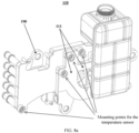
- the temperature sensor 170 is mounted on a designated cooling connection pipeline 111 on the multi-channel integration board 110, and is configured to measure a temperature of a cooling liquid (e.g., water) in the designated cooling connection pipeline 111.
- a quantity of temperature sensors 170 is set based on an actually-required vehicle thermal management principle diagram. For example, the quantity may be four.
- the thermal management components may further include the two-port proportional valve 192 (not illustrated in FIG. 1 or FIG. 2 ).
- the two-port proportional valve 192 may be an intelligent proportional valve, which is disposed on the cooling connection pipeline 111 between one of the water pumps 140 and the condenser 160.
- the embodiments of the present disclosure are about the specific integrated thermal management components (which may include the expansion tank 120, the multi-port valve 130, the water pump 140, the heat exchanger 150, the condenser 160, the temperature sensor 170, the dryer 180, the electronic expansion valve 191, the air conditioning pipeline 190, etc.).
- a more compact arrangement of the thermal management components is realized through a reasonable layout of the thermal management components on the multi-channel integration board 110, and a layout of the cooling connection pipelines 111 in the multi-channel integration board 110 is optimized, reducing manufacturing difficulty.
- the air conditioning pipeline 190 further has an air conditioning pipeline external port configured to be connected to a refrigerant connection pipeline of the thermal management object associated with the air conditioning of the vehicle.
- the thermal management object associated with the air conditioning of the vehicle includes a built-in condenser and a compressor of an air conditioning main unit
- the air conditioning pipeline external port includes a built-in condenser inlet port 193, a built-in condenser outlet port 194, a compressor inlet port 195, and a compressor outlet port 196.
- Each of the built-in condenser inlet port 193 and the built-in condenser outlet port 194 is configured to be connected to a refrigerant connection pipeline of a built-in condenser of an air conditioning main unit of a vehicle.
- Each of the compressor inlet port 195 and the compressor outlet port 196 is configured to be connected to a refrigerant connection pipeline of a compressor of the vehicle.
- Positions of the built-in condenser inlet port 193, the built-in condenser outlet port 194, the compressor inlet port 195, and the compressor outlet port 196 are distributed based on arrangement positions of the built-in condenser and the compressor to enable the refrigerant connection pipeline of the built-in condenser and the refrigerant connection pipeline of the compressor to be the shortest.
- the compressor inlet port 195 and the compressor outlet port 196 are located on a same side as the expansion tank 120 and located below the expansion tank 120, and the built-in condenser inlet port 193 and the built-in condenser outlet port 194 are located on a same side as the condenser and located below an end of the multi-channel integration board 110 at which the condenser 160 is located.
- the air conditioning pipeline external port may further include a built-in evaporator inlet port 197 configured to be connected to a refrigerant connection pipeline of a built-in evaporator of the air conditioning main unit.
- a position of the built-in evaporator inlet port 197 is distributed based on an arrangement position of the built-in evaporator to enable the refrigerant connection pipeline of the built-in evaporator to be the shortest.
- the built-in evaporator inlet port 197 is located on a same side as the condenser 160 and located below an end of the multi-channel integration board 110 at which the condenser 160 is located.
- the multi-channel integration board 110 further has a plurality of cooling pipeline external ports formed thereon.
- Each of the plurality of cooling pipeline external ports is configured to be connected to a cooling liquid connection pipeline of a thermal management object of a vehicle.
- Positions of the plurality of external cooling pipeline external ports are arranged based on an arrangement position of the thermal management object to enable the cooling liquid connection pipeline of the thermal management object to be the shortest.
- the thermal management object here may include, but is not limited to, a DC-DC converter, a High Voltage Coolant Heater (HVCH), an On-Board Charger (OBC), a battery pack, a radiator, or the like.
- thermal management integration module 100 As a whole, corresponding thermal management objects (such as the DC-DC converter, the HVCH, the OBC, the battery pack, the radiator, the compressor, the built-in condenser and the built-in evaporator of the air conditioning main unit, or the like described above) may be construed as counterparts of the entire thermal management integration module 100.
- positions of the cooling pipeline external port and the air conditioning pipeline external port are set uniformly to enable a connection pipeline of the thermal management object to be the shortest, further reducing the costs and the weight of the whole vehicle.
- the cooling pipeline external port includes a radiator liquid-inlet port 112, a radiator liquid-outlet port 113, a DC-DC converter liquid-inlet port 114, a high pressure liquid heater liquid-inlet port 115, a high pressure liquid heater liquid-outlet port 118, an on-vehicle charger liquid-outlet port 116, a battery pack liquid-inlet port 119, and a battery pack liquid-outlet port 117.
- the radiator liquid-inlet port 112, the radiator liquid-outlet port 113, and the DC-DC converter liquid-inlet port 114 are located at an end of the multi-channel integration board 110 in a length direction (in some embodiments, the end at which the water pump 140 is located).
- the radiator liquid-inlet port 112 and the radiator liquid-outlet port 113 protrude towards a side of the multi-channel integration board 110 (in some embodiments, the side on which the water pump 140 is located).
- the high pressure liquid heater liquid-inlet port 115, the on-vehicle charger liquid-outlet port 116, the battery pack liquid-outlet port 117, the high pressure liquid heater liquid-outlet port 118, and the battery pack liquid-inlet port 119 are located at the other end of the multi-channel integration board 110 in the length direction (in some embodiments, the end at which the condenser 160 is located), are arranged in a width direction of the multi-channel integration board 110 sequentially, and each have a protrusion direction identical to a protrusion direction of the radiator liquid-inlet port 112. This arrangement can take into account the space utilization, aesthetics, and the convenience of usability of ports.
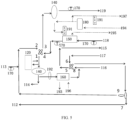
- FIG. 5 illustrates a schematic diagram of a principle of the thermal management integration module 100 according to an embodiment of the present disclosure.
- two electronic water pumps 140 which are referred to as the battery water pump and the motor water pump, respectively
- an one-piece nine-port valve a water-cooled condenser 160
- a heat exchanger 150 an expansion tank 120
- four temperature sensors 170 water temperature sensors
- an intelligent two-port proportional valve 192 a dryer 180
- two electronic expansion valves 191 and an air conditioning pipeline 190
- the one-piece nine-port valve is equivalent to two four-port solenoid valves and one three-port solenoid valve, with number 1 to number 9 indicating nine ports of the one-piece nine-port valve.
- the solid line indicates the cooling connection pipeline 111 in the multi-channel integration board 110.
- the arrow on the solid line indicates a flow direction of the cooling liquid in the cooling connection pipeline 111.
- the dotted line indicates the air conditioning pipeline 190.
- the arrow on the dotted line indicates a flow direction of the refrigerant in the air conditioning pipeline 190.
- Embodiment 2 Differences between Embodiment 2 and Embodiment 1 mainly lie in the following description.
- the thermal management components, associated with the refrigerant circulation loop of the air conditioning of the vehicle, that are integrated on the multi-channel integration board 110 include no dryer 180 and only one electronic expansion valve 191.
- the electronic expansion valve 191 is mounted on the same side of the multi-channel integration board 110 as the heat exchanger 150 and close to a position of the heat exchanger 150, and the air conditioning pipeline 190 is connected to the electronic expansion valve 191, the heat exchanger 150, and the condenser 160.
- the main body portion of the air conditioning pipeline 190 extends on the side of the multi-channel integration board 110 on which the expansion tank 120 is located, and forms the compressor outlet port 196 on the same side as the expansion tank 120 and below the expansion tank 120.
- the built-in condenser outlet port 194 is formed on a valve seat of the electronic expansion valve 191.
- the built-in condenser inlet port 193 and the compressor inlet port 195 are formed on the water-cooled condenser 160 and the heat exchanger 150, respectively.
- the multi-channel integration board 110 further has a plurality of mounting lugs 198 disposed thereon and configured for mounting and fixing the thermal management integration module 100 to a body of the vehicle.
- Each mounting lug 198 protrudes outwards from an edge of the multi-channel integration board 110, and includes a root connected to the edge of the multi-channel integration board 110 and a head facing away from the multi-channel integration board 110.
- the head has a central through hole defined thereon, and is configured to be engaged with a fastener capable of passing through the central through hole to mount and fix the thermal management integration module 100 to the body of the vehicle.
- at least three mounting lugs 198 are provided.
- three mounting lugs 198 are provided.
- the three mounting lugs 198 may be disposed on three edges of the multi-channel integration board 110, respectively.
- a ring-shaped cushion may be disposed in the central through hole of each mounting lug 198.
- a thickness of the cushion is greater than a thickness of the head of the mounting lug 198, to enable a surface of the cushion to protrude beyond the central through hole.
- the cushion can cushion a collision between the mounting lug 198 and the body of the vehicle to which the thermal management integration module 100 is fixed.
- the cushion may be made of rubber.
- the expansion tank 120 is pre-integrated on the multi-channel integration board 110 by means of hot plate welding, etc.
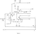
- the implementation principle of the thermal management integration module 100 is as illustrated in FIG. 9 .
- two electronic water pumps 140 which are referred to as the battery water pump and the motor water pump, respectively
- the one-piece nine-port valve the water-cooled condenser 160, the heat exchanger 150, the expansion tank 120, four temperature sensors 170 (water temperature sensors), the intelligent two-port proportional valve 192, one electronic expansion valve 191, and the air conditioning pipeline 190 are integrated on the multi-channel integration board 110.
- the one-piece nine-port valve is equivalent to two four-port solenoid valves and one three-port solenoid valve, with number 1 to number 9 indicating nine ports of the one-piece nine-port valve.
- the solid line indicates the cooling connection pipeline 111 in the multi-channel integration board 110.
- the arrow on the solid line indicates a flow direction of the cooling liquid in the cooling connection pipeline 111.
- the dotted line indicates the air conditioning pipeline 190.
- the arrow on the dotted line indicates a flow direction of the refrigerant in the air conditioning pipeline 190.
- radiator liquid-inlet port 112 (which, in some embodiments, are the radiator liquid-inlet port 112, the radiator liquid-outlet port 113, the DC-DC converter liquid-inlet port 114, the high pressure liquid heater liquid-inlet port 115, the high pressure liquid heater liquid-outlet port 118, the on-vehicle charger liquid-outlet port 116, the battery pack liquid-inlet port 119, the battery pack liquid-outlet port 117, the built-in condenser inlet port 193, the built-in condenser outlet port 194, the compressor inlet port 195, and the compressor outlet port 196) are provided to form different thermal management loops.
- the embodiments of the present disclosure further provide an electric vehicle including the thermal management integration module 100 according to any or a combination of the above-mentioned embodiments.
- the thermal management integration module 100 of the present disclosure can allow the costs of each electric vehicle adopting the thermal management integration module 100 to be reduced by more than 300 RMB and the weight of each electric vehicle to be reduced by more than 2 kg.
Landscapes
- Engineering & Computer Science (AREA)
- Mechanical Engineering (AREA)
- Physics & Mathematics (AREA)
- Thermal Sciences (AREA)
- General Engineering & Computer Science (AREA)
- Combustion & Propulsion (AREA)
- Chemical & Material Sciences (AREA)
- Life Sciences & Earth Sciences (AREA)
- Sustainable Development (AREA)
- Sustainable Energy (AREA)
- Air-Conditioning For Vehicles (AREA)
- Cooling, Air Intake And Gas Exhaust, And Fuel Tank Arrangements In Propulsion Units (AREA)
- Arrangement Or Mounting Of Propulsion Units For Vehicles (AREA)
- Electric Propulsion And Braking For Vehicles (AREA)
Abstract
Description
- The present disclosure relates to the field of vehicle technologies, and more particularly, to a thermal management integration module and an electric vehicle.
- Based on a vehicle thermal management principle diagram, an electric vehicle often requires a number of thermal management components, such as an expansion tank, at least two cooling water pumps, a heat exchanger, a water-cooled condenser, at least two water temperature sensors, a four-port solenoid valve, a three-port solenoid valve, and a cooling connection pipeline. To increase a range of a pure electric vehicle, the design of the vehicle thermal management diagram needs to be adapted to more and more working conditions, and thus more and more thermal management components are required. In the related art, these thermal management components are dispersed. On the one hand, the dispersed thermal management components will occupy a large arrangement space. On the other hand, such a dispersed arrangement leads to a need to use a large number of cooling pipelines for connections among the thermal management components, but the large number of cooling pipelines bring about a complex cabin, a difficult arrangement, and higher costs. In addition, the dispersed arrangement also leads to an increase in lengths of the cooling connection pipelines and an air conditioning pipeline, which in turn leads to an increase in a system flow resistance and a heat leakage value, requiring a water pump having higher power and longer Positive Temperature Coefficient (PTC) heating time or increased PTC heating power to meet system requirements. This also leads to an increase of system costs. Therefore, it is an urgent to-be-solved technical problem in the related art regarding how to develop a new type of thermal management integration module that is cost-effective, lightweight, and with a reduced arrangement space.
- In view of the above problems, a thermal management integration module and an electric vehicle that overcome the above problems or at least partially solve the above problems are provided.
- An object of the present disclosure is to provide a thermal management integration module with low costs, a light weight, and a small arrangement space.
- A further object of the present disclosure is to realize a more compact arrangement of thermal management components through a reasonable layout of the thermal management components on a multi-channel integration board, and to optimize a layout of cooling connection pipelines in the multi-channel integration board, reducing manufacturing difficulty.
- A further object of the present disclosure is to make a connection pipeline of a thermal management object with both a cooling pipeline external port and an air conditioning pipeline external port of the thermal management integration module the shortest, to further reduce costs and a weight of the whole vehicle.
- In particular, in an aspect, according to the embodiments of the present disclosure, a thermal management integration module is provided. The thermal management integration module includes: a multi-channel integration board having a plurality of cooling connection pipelines formed therein, the multi-channel integration board being configured as a carrier member for the thermal management integration module; and at least two thermal management components mounted on the multi-channel integration board and connected to each other by the plurality of cooling connection pipelines.
- In some embodiments, the at least two thermal management components include at least two of an expansion tank, a multi-port valve, a water pump, a heat exchanger, a condenser, a temperature sensor, a dryer, an electronic expansion valve, a two-port proportional valve, or an air conditioning pipeline.
- In some embodiments, when the at least two thermal management components include the water pump, at least two water pumps are provided, and the at least two water pumps are mounted on a same side of an end of the multi-channel integration board in a length direction and are arranged in a width direction of the multi-channel integration board; and when the at least two thermal management components further include the expansion tank, the expansion tank is mounted at a position on a side of the multi-channel integration board opposite to the water pump.
- In some embodiments, when the at least two thermal management components include the multi-port valve, the multi-port valve is mounted on a middle portion of a side of the multi-channel integration board, and the multi-port valve is a nine-port valve.
- In some embodiments, when the at least two thermal management components further include the heat exchanger, the heat exchanger is mounted on the same side of the multi-channel integration board as the multi-port valve and close to a position of the multi-port valve; and when the at least two thermal management components further include the condenser, the condenser is mounted at an end of the multi-channel integration board in a length direction, located on the same side of the multi-channel integration board as the heat exchanger, and adjacent to the heat exchanger.
- In some embodiments, when the at least two thermal management components further include the dryer, the electronic expansion valve, and the air conditioning pipeline, the dryer and the electronic expansion valve are respectively mounted at positions on the side of the multi-channel integration board opposite to the heat exchanger, and the air conditioning pipeline is connected to the dryer, the electronic expansion valve, the heat exchanger, and the condenser; or when the at least two thermal management components further include the electronic expansion valve and the air conditioning pipeline, the electronic expansion valve is mounted on the same side of the multi-channel integration board as the heat exchanger and close to a position of the heat exchanger, and the air conditioning pipeline is connected to the electronic expansion valve, the heat exchanger, and the condenser.
- In some embodiments, the air conditioning pipeline has a built-in condenser inlet port, a built-in condenser outlet port, a compressor inlet port, and a compressor outlet port; each of the built-in condenser inlet port and the built-in condenser outlet port is configured to be connected to a refrigerant connection pipeline of a built-in condenser of an air conditioning main unit of a vehicle, and each of the compressor inlet port and the compressor outlet port is configured to be connected to a refrigerant connection pipeline of a compressor of the vehicle; and positions of the built-in condenser inlet port, the built-in condenser outlet port, the compressor inlet port, and the compressor outlet port are distributed based on arrangement positions of the built-in condenser and the compressor to enable the refrigerant connection pipeline of the built-in condenser and the refrigerant connection pipeline of the compressor to be the shortest.
- In some embodiments, the multi-channel integration board further has a plurality of cooling pipeline external ports formed thereon, each of the plurality of cooling pipeline external ports is configured to be connected to a cooling liquid connection pipeline of a thermal management object of a vehicle, and positions of the plurality of external cooling pipeline external ports are arranged based on an arrangement position of the thermal management object to enable the cooling liquid connection pipeline of the thermal management object to be the shortest.
- In some embodiments, the cooling pipeline external port includes a radiator liquid-inlet port, a radiator liquid-outlet port, a Direct Current-Direct Current (DC-DC) converter liquid-inlet port, a high pressure liquid heater liquid-inlet port, a high pressure liquid heater liquid-outlet port, an on-vehicle charger liquid-outlet port, a battery pack liquid-inlet port, and a battery pack liquid-outlet port; the radiator liquid-inlet port, the radiator liquid-outlet port, and the DC-DC converter liquid-inlet port are located at an end of the multi-channel integration board in a length direction, and the radiator liquid-inlet port and the radiator liquid-outlet port protrude towards a side of the multi-channel integration board; and the high pressure liquid heater liquid-inlet port, the on-vehicle charger liquid-outlet port, the battery pack liquid-outlet port, the high pressure liquid heater liquid-outlet port, and the battery pack liquid-inlet port are located at the other end of the multi-channel integration board in the length direction, are arranged in a width direction of the multi-channel integration board sequentially, and each have a protrusion direction identical to a protrusion direction of the radiator liquid-inlet port.
- According to one embodiment of the present disclosure, an electric vehicle is further provided. The electric vehicle includes the thermal management integration module according to any of the above embodiments.
- The thermal management integration module of the present disclosure adopts the design of the multi-channel integration board. The plurality of cooling connection pipelines is formed in the multi-channel integration board. The multi-channel integration board can not only serve as a connection channel between different thermal management components, but also serve as a carrier member for the entire integration module to enable the thermal management components to be integrated on the multi-channel integration board, forming the thermal management integration module with low costs, a light weight, and a small arrangement space. Compared with a conventional vehicle thermal management system, the thermal management integration module of the present disclosure can allow costs of each vehicle to be reduced by more than 300 RMB and a weight of each vehicle to be reduced by more than 2 kg. In addition, the thermal management integration module of the present disclosure can be supplied in a modular form, which greatly optimizes supplier management and working hours of manufacturing workers.
- Further, for specific integrated thermal management components (which in some embodiments may include the expansion tank, the multi-port valve, the water pump, the heat exchanger, the condenser, the temperature sensor, the dryer, the electronic expansion valve, the air conditioning pipeline, or the like), a more compact arrangement of the thermal management components is realized through a reasonable layout of the thermal management components on the multi-channel integration board, and the layout of cooling connection pipelines in the multi-channel integration board is optimized, reducing the manufacturing difficulty.
- Further, the thermal management integration module may further provide a plurality of cooling pipeline external ports and air conditioning pipeline external ports that are configured to be connected to a connection pipeline of the thermal management object. In addition, positions of the cooling pipeline external ports and the air conditioning pipeline external ports are arranged based on the arrangement position of the thermal management object to enable the connection pipeline of the thermal management object to be the shortest, further reducing the costs and weight of the whole vehicle.
- Further, since the thermal management integration module of the present disclosure can save a large number of cooling connection pipelines and air conditioning pipelines, a flow resistance and a heat leakage value of the system are reduced, which can lower a power requirement of the water pump, and reduce PTC heating time or PTC heating power, further decreasing the costs and power consumption of the whole vehicle and increasing a range. It was estimated that a power requirement of the water pump can be reduced by about 20%, and PTC heating power consumption can be reduced by about 200 W, and the range can be increased by about 10 km.
- The above description is merely an overview of the technical solutions of the present disclosure. To facilitate a clear understanding of technical means of the present disclosure and the implementations of the technical solutions in accordance with the contents of the specification, and to clarify and explain the above and other objects, features, and advantages of the present disclosure, specific embodiments of the present disclosure will be described below.
- The above and other objects, advantages, and features of the present disclosure will be clearly understood by those skilled in the art in the light of the following detailed description of specific embodiments of the present disclosure made in conjunction with the accompanying drawings.
- Some specific embodiments of the present disclosure will be described in detail below in an exemplary and non-restrictive manner with reference to the accompanying drawings. Same or similar components or portions are denoted by same reference numerals in the accompanying drawings. It should be understood by those skilled in the art that these accompanying drawings are not necessarily drawn to scale.
-
FIG. 1 illustrates a schematic structural view of a thermal management integration module according to an embodiment of the present disclosure, as viewed from a side thereof. -
FIG. 2 illustrates a schematic structural view of the thermal management integration module illustrated inFIG. 1 , as viewed from another side thereof. -
FIG. 3 illustrates a schematic structural view of a lower right corner of the thermal management integration module illustrated inFIG. 1 , as viewed from another angle. -
FIG. 4 illustrates a schematic structural view of a multi-channel integration board of a thermal management integration module according to an embodiment of the present disclosure. -
FIG. 5 illustrates a schematic diagram of principles of a thermal management integration module according to an embodiment of the present disclosure. -
FIG. 6 illustrates a schematic structural view of a thermal management integration module according to another embodiment of the present disclosure, as viewed from a side thereof. -
FIG. 7 illustrates a schematic structural view of the thermal management integration module illustrated inFIG. 6 , as viewed from another side thereof. -
FIG. 8a illustrates a schematic structural view of a multi-channel integration board of a thermal management integration module according to another embodiment of the present disclosure, as viewed from a side of the multi-channel integration board. -
FIG. 8b illustrates a schematic structural view of the multi-channel integration board ofFIG. 8a , as viewed from another side thereof. -
FIG. 9 illustrates a schematic diagram of a principle of a thermal management integration module according to another embodiment of the present disclosure. - Some exemplary embodiments of the present disclosure will be described in detail below with reference to the accompanying drawings. Although some exemplary embodiments of the present disclosure are illustrated in the drawings, it should be understood that the present disclosure may be embodied in various forms and should not be construed as being limited to the embodiments set forth herein. Instead, these embodiments are provided for a thorough understanding of the present disclosure, and these embodiments can fully convey the scope of the present disclosure to those skilled in the art.
- Since thermal management components in a conventional vehicle thermal management system are arranged in a dispersed manner, the conventional vehicle thermal management system has the following problems: (1) Lengths of a cooling pipeline and an air conditioning pipeline increase, which leads to a rise in a flow resistance of the system, requiring the use of a high-power water pump to meet a system requirement. (2) Increase in the lengths of the cooling pipeline and the air conditioning pipeline further leads to an increase in a heat leakage value of the system, raising a need to lengthen PTC heating time or increase PTC heating power to meet a heating requirement of the system. (3) Thermal management components such as an expansion tank, a motor water pump assembly, a battery water pump assembly, a heat exchanger, a water-cooled condenser, a water temperature sensor, two four-port solenoid valves, a three-port solenoid valve, a two-port proportional valve, an air conditioning electronic expansion valve, and an air conditioning pipeline are arranged in a dispersed manner, and connected by the cooling pipeline and the air conditioning pipeline, resulting in a complex space requirement for an arrangement. (4) The above-mentioned thermal management components are supplied by different suppliers and assembled at the base, which make the working hours longer and are not conducive to supplier management. (5) A large number of cooling pipelines and air conditioning pipelines need to be used, leading to an increase in costs and a weight of the whole vehicle.
- To solve or at least partially solve the above technical problems, the embodiments of the present disclosure provide a thermal management integration module.
FIG. 1 illustrates a schematic structural view of a thermalmanagement integration module 100 according to an embodiment of the present disclosure, as viewed from a side thereof.FIG. 2 illustrates a schematic structural view of the thermalmanagement integration module 100 illustrated inFIG. 1 , as viewed from another side thereof.FIG. 6 illustrates a schematic structural view of the thermalmanagement integration module 100 according to another embodiment of the present disclosure, as viewed from a side thereof.FIG. 7 illustrates a schematic structural view of the thermalmanagement integration module 100 illustrated inFIG. 6 , as viewed from another side thereof. As illustrated inFIG. 1 ,FIG. 2 ,FIG. 6 , andFIG. 7 , the thermalmanagement integration module 100 may generally include amulti-channel integration board 110 and at least two thermal management components. Themulti-channel integration board 110 has a plurality of cooling connection pipelines 111 (e.g., water lines) formed therein and configured as connection channels between different thermal management components. In addition, themulti-channel integration board 110 may further act as a carrier member for the entire thermalmanagement integration module 100 to carry the thermal management components. The at least two thermal management components are mounted on themulti-channel integration board 110 and connected to each other by thecooling connection pipelines 111 in themulti-channel integration board 110. - The thermal
management integration module 100 according to the embodiments of the present disclosure adopts the design of themulti-channel integration board 110. The plurality ofcooling connection pipelines 111 is formed in themulti-channel integration board 110. Themulti-channel integration board 110 can not only serve as a connection channel between different thermal management components, but also serve as the carrier member for the entire integration module to enable the thermal management components to be integrated on themulti-channel integration board 110, forming the thermalmanagement integration module 100 with low costs, a light weight, and a small arrangement space. Since the integrated thermal management components are connected to each other by using thecooling connection pipelines 111 in themulti-channel integration board 110 without an additional connection pipeline, the costs are reduced while a cabin is beautified. In addition, the thermal management components are integrated and arranged on themulti-channel integration board 110 to form a one-piece module, and thus the thermalmanagement integration module 100 of the present disclosure can be supplied in a modular form, which greatly optimizes supplier management and working hours of manufacturing workers. - The
multi-channel integration board 110 is a key component of the thermalmanagement integration module 100 of the present disclosure. Thecooling connection pipeline 111 inside themulti-channel integration board 110 is designed based on a connection method for respective thermal management components in a vehicle thermal management principle diagram that is actually applied, to realize a pipeline (e.g., water line) connection between the thermal management components.FIG. 4 illustrates a schematic structural view of amulti-channel integration board 110 of a thermalmanagement integration module 100 according to an embodiment of the present disclosure. As illustrated inFIG. 4 , eachcooling connection pipeline 111 inside themulti-channel integration board 110 extends substantially along a length direction of themulti-channel integration board 110. In use, the thermalmanagement integration module 100 is mounted in a manner that the length direction of themulti-channel integration board 110 is substantially parallel to a horizontal direction and a width direction of themulti-channel integration board 110 is substantially perpendicular to a vehicle chassis, minimizing a flow resistance of a cooling liquid (e.g., water), flowing through eachcooling connection pipeline 111, generated due to gravity. - To ensure thermal insulation between respective
cooling connection pipelines 111 and to reduce a heat loss, themulti-channel integration board 110 may be made of a thermally insulating plastic such as Polypropylene (PP) or Polyamide 66 (PA66). By using themulti-channel integration board 110 made of PP or PA66, the strength of themulti-channel integration board 110 can be ensured while ensuring thermal insulation, which can improve structural stability and durability of the thermalmanagement integration module 100. To facilitate molding of themulti-channel integration board 110, a separate molding method may be used. Themulti-channel integration board 110 is divided into a main body portion and a cover plate portion in a thickness direction of themulti-channel integration board 110. Acooling connection pipeline 111 having openings is formed on the main body portion. After the main body portion and the cover plate portion are injection molded separately, the main body portion and the cover plate portion are connected and fixed by welding to obtain themulti-channel integration board 110. Welding methods include, but are not limited to, hot plate welding, friction welding, laser welding, etc. - The integrated thermal management components may be selected based on actual requirements of vehicle thermal management. Also, mounting positions of the integrated thermal management components on the
multi-channel integration board 110 may be determined based on shapes and sizes of actually-selected thermal management components, a connection method and an operation method of the actually-selected thermal management components in the vehicle thermal management principle diagram, or the like. Accordingly, fixation structures for these thermal management components are designed on corresponding positions of themulti-channel integration board 110. - In general, the thermal management components integrated on the
multi-channel integration board 110 may include at least two of anexpansion tank 120, amulti-port valve 130, awater pump 140, aheat exchanger 150, a condenser 160 (e.g., a water-cooled condenser), atemperature sensor 170, adryer 180, anelectronic expansion valve 191, a two-portproportional valve 192, anair conditioning pipeline 190, or the like. - A specific structure of the thermal
management integration module 100 of the present disclosure is described below in conjunction with embodiments. - In an embodiment, the
multi-channel integration board 110 has a structure illustrated inFIG. 4 . - As illustrated in
FIG. 1 andFIG. 2 , in the embodiment, the thermal management components integrated on themulti-channel integration board 110 may include at least two of theexpansion tank 120, themulti-port valve 130, thewater pump 140, theheat exchanger 150, the water-cooledcondenser 160, thetemperature sensor 170, thedryer 180, theelectronic expansion valve 191, the two-portproportional valve 192, or theair conditioning pipeline 190. - When the thermal management components include the
water pump 140, in accordance with the vehicle thermal management principle diagram, usually at least twowater pumps 140 are provided. One of the two water pumps 140 (which may be referred to as a motor water pump) is configured to drive the cooling liquid in a motor cooling loop of a vehicle to flow, while the other one of the two water pumps 140 (which may be referred to as a battery water pump) is configured to drive the cooling liquid in a battery pack cooling loop of the vehicle to flow. The at least twowater pumps 140 may be mounted on a same side of an end of themulti-channel integration board 110 in a length direction and are arranged in a width direction of themulti-channel integration board 110. Such an arrangement of the water pumps facilitates mounting management of the water pumps 140 and allows for more efficient use of a mounting space on themulti-channel integration board 110. In a specific embodiment, a pump housing of thewater pump 140 has a cylindrical shape. Accordingly, as illustrated inFIG. 4 , a first fixation member having a circular ring shape is disposed at a water pump fixation position on themulti-channel integration board 110. A plurality of first fixation blocks protruding circumferentially and evenly distributed is disposed at an outer periphery of the first fixation member. A first through hole is defined in each first fixation block. A second fixation member corresponding to the first fixation member is disposed at an end of the pump housing of thewater pump 140. A second fixation block corresponding to the first fixation block is disposed on an outer periphery of the second fixation member. A second through hole corresponding to the first through hole is defined in each second fixation block. During mounting, a fastener (such as a bolt) passes through the corresponding second through hole and first through hole to fix thewater pump 140 to themulti-channel integration board 110. - Further, the thermal management components may further include the
expansion tank 120, and theexpansion tank 120 is mounted at a position on a side of themulti-channel integration board 110 opposite to thewater pump 140. Since theexpansion tank 120 has a large volume and is usually connected to one of the water pumps 140, such an arrangement can minimize a length of the cooling connection pipeline 111 (connection channel) between theexpansion tank 120 and thewater pump 140, to reduce the flow resistance, and allow the mounting space on themulti-channel integration board 110 to be more effectively utilized, thereby saving the arrangement space. A pressure cover is disposed at a top of theexpansion tank 120. - The thermal management components may include the multi-port valve 130 (e.g., a four-port solenoid valve, a three-port solenoid valve, etc.). According to the vehicle thermal management principle diagram, ports of the
multi-port valve 130 are connected to a plurality of thermal management components in a vehicle thermal management system to control on/off of different thermal management loops. Thus, themulti-port valve 130 may be mounted on a middle portion of a side of themulti-channel integration board 110 to facilitate a connection of themulti-port valve 130 to other thermal management components. In some embodiments, themulti-port valve 130 is a nine-port valve, which can replace one conventional three-port solenoid valve and two conventional four-port solenoid valves in the vehicle thermal management system to achieve nine channels, further reducing the costs and weight of the whole vehicle. In some embodiments, themulti-port valve 130 may be a one-piece nine-port valve having a plate-like mounting panel. Nine channel interfaces (i.e. ports) are intensively disposed on the mounting panel to achieve uniformity of port positions. The one-piece nine-port valve having such a structure can be mounted on themulti-channel integration board 110 easily, which can further reduce the arrangement space occupied by themulti-port valve 130 and greatly improve the arrangement space and aesthetics of distribution of thecooling connection pipelines 111 in communication with these ports. - The thermal management components may further include the
heat exchanger 150. Theheat exchanger 150 may be mounted on the same side of themulti-channel integration board 110 as themulti-port valve 130 and close to a position of themulti-port valve 130, which can effectively shorten a length of a connection pipeline between theheat exchanger 150 and the port of themulti-port valve 130. In a specific embodiment, themulti-port valve 130 may be mounted on an upper side of the middle portion of the multi-channel integration board 110 (the upper side here refers to an upper side of the thermalmanagement integration module 100 in a vertical direction when the thermalmanagement integration module 100 is in use). Theheat exchanger 150 is mounted on a lower side of the middle portion. Specifically, a multi-port valve fixation position and a heat exchanger fixation position are as illustrated inFIG. 4 . - The thermal management components may further include the condenser 160 (e.g., the water-cooled condenser 160). Since the
condenser 160 in the vehicle thermal management system usually has a large volume, thecondenser 160 may be mounted at an end of themulti-channel integration board 110 in a length direction to ensure that thecondenser 160 has a sufficient arrangement space. In addition, thecondenser 160 may be located on the same side of themulti-channel integration board 110 as theheat exchanger 150, and adjacent to theheat exchanger 150, to improve utilization of the mounting space. Of course, it should be understood by those skilled in the art that, when both theexpansion tank 120 and thecondenser 160 are integrated on themulti-channel integration board 110, theexpansion tank 120 and thecondenser 160 are respectively mounted at two ends of themulti-channel integration board 110 in the length direction, to ensure a sufficient arrangement space for each of theexpansion tank 120 and thecondenser 160. - The thermal management components may further include components in a refrigerant circulation loop of an air conditioning of the vehicle, such as the
dryer 180, theelectronic expansion valve 191, and theair conditioning pipeline 190. Thedryer 180 and theelectronic expansion valve 191 are respectively mounted at positions on the side of themulti-channel integration board 110 opposite to theheat exchanger 150. Theair conditioning pipeline 190, as a refrigerant flowing pipeline, is connected to thedryer 180, theelectronic expansion valve 191, theheat exchanger 150, and thecondenser 160, to realize circulation of a refrigerant in a compressor of the air conditioning. A main body portion of theair conditioning pipeline 190 extends on the side of themulti-channel integration board 110 on which thedryer 180 is located. A quantity ofelectronic expansion valves 191 is set based on an actually-required vehicle thermal management principle diagram. For example, the quantity may be two. - The thermal management components may further include the
temperature sensor 170. Thetemperature sensor 170 is mounted on a designatedcooling connection pipeline 111 on themulti-channel integration board 110, and is configured to measure a temperature of a cooling liquid (e.g., water) in the designatedcooling connection pipeline 111. A quantity oftemperature sensors 170 is set based on an actually-required vehicle thermal management principle diagram. For example, the quantity may be four. - The thermal management components may further include the two-port proportional valve 192 (not illustrated in
FIG. 1 orFIG. 2 ). The two-portproportional valve 192 may be an intelligent proportional valve, which is disposed on thecooling connection pipeline 111 between one of the water pumps 140 and thecondenser 160. - The embodiments of the present disclosure are about the specific integrated thermal management components (which may include the
expansion tank 120, themulti-port valve 130, thewater pump 140, theheat exchanger 150, thecondenser 160, thetemperature sensor 170, thedryer 180, theelectronic expansion valve 191, theair conditioning pipeline 190, etc.). A more compact arrangement of the thermal management components is realized through a reasonable layout of the thermal management components on themulti-channel integration board 110, and a layout of thecooling connection pipelines 111 in themulti-channel integration board 110 is optimized, reducing manufacturing difficulty. - Further, as illustrated in
FIG. 2 andFIG. 3 , theair conditioning pipeline 190 further has an air conditioning pipeline external port configured to be connected to a refrigerant connection pipeline of the thermal management object associated with the air conditioning of the vehicle. In some embodiments, the thermal management object associated with the air conditioning of the vehicle includes a built-in condenser and a compressor of an air conditioning main unit, and the air conditioning pipeline external port includes a built-incondenser inlet port 193, a built-incondenser outlet port 194, acompressor inlet port 195, and acompressor outlet port 196. Each of the built-incondenser inlet port 193 and the built-incondenser outlet port 194 is configured to be connected to a refrigerant connection pipeline of a built-in condenser of an air conditioning main unit of a vehicle. Each of thecompressor inlet port 195 and thecompressor outlet port 196 is configured to be connected to a refrigerant connection pipeline of a compressor of the vehicle. Positions of the built-incondenser inlet port 193, the built-incondenser outlet port 194, thecompressor inlet port 195, and thecompressor outlet port 196 are distributed based on arrangement positions of the built-in condenser and the compressor to enable the refrigerant connection pipeline of the built-in condenser and the refrigerant connection pipeline of the compressor to be the shortest. In some embodiments, for example, thecompressor inlet port 195 and thecompressor outlet port 196 are located on a same side as theexpansion tank 120 and located below theexpansion tank 120, and the built-incondenser inlet port 193 and the built-incondenser outlet port 194 are located on a same side as the condenser and located below an end of themulti-channel integration board 110 at which thecondenser 160 is located. - The air conditioning pipeline external port may further include a built-in
evaporator inlet port 197 configured to be connected to a refrigerant connection pipeline of a built-in evaporator of the air conditioning main unit. A position of the built-inevaporator inlet port 197 is distributed based on an arrangement position of the built-in evaporator to enable the refrigerant connection pipeline of the built-in evaporator to be the shortest. In some embodiments, the built-inevaporator inlet port 197 is located on a same side as thecondenser 160 and located below an end of themulti-channel integration board 110 at which thecondenser 160 is located. - In addition, as illustrated in
FIG. 1 , themulti-channel integration board 110 further has a plurality of cooling pipeline external ports formed thereon. Each of the plurality of cooling pipeline external ports is configured to be connected to a cooling liquid connection pipeline of a thermal management object of a vehicle. Positions of the plurality of external cooling pipeline external ports are arranged based on an arrangement position of the thermal management object to enable the cooling liquid connection pipeline of the thermal management object to be the shortest. The thermal management object here may include, but is not limited to, a DC-DC converter, a High Voltage Coolant Heater (HVCH), an On-Board Charger (OBC), a battery pack, a radiator, or the like. - Considering the thermal
management integration module 100 as a whole, corresponding thermal management objects (such as the DC-DC converter, the HVCH, the OBC, the battery pack, the radiator, the compressor, the built-in condenser and the built-in evaporator of the air conditioning main unit, or the like described above) may be construed as counterparts of the entire thermalmanagement integration module 100. By fully considering arrangement positions of the counterparts, positions of the cooling pipeline external port and the air conditioning pipeline external port are set uniformly to enable a connection pipeline of the thermal management object to be the shortest, further reducing the costs and the weight of the whole vehicle. - In some embodiments, the cooling pipeline external port includes a radiator liquid-
inlet port 112, a radiator liquid-outlet port 113, a DC-DC converter liquid-inlet port 114, a high pressure liquid heater liquid-inlet port 115, a high pressure liquid heater liquid-outlet port 118, an on-vehicle charger liquid-outlet port 116, a battery pack liquid-inlet port 119, and a battery pack liquid-outlet port 117. The radiator liquid-inlet port 112, the radiator liquid-outlet port 113, and the DC-DC converter liquid-inlet port 114 are located at an end of themulti-channel integration board 110 in a length direction (in some embodiments, the end at which thewater pump 140 is located). The radiator liquid-inlet port 112 and the radiator liquid-outlet port 113 protrude towards a side of the multi-channel integration board 110 (in some embodiments, the side on which thewater pump 140 is located). The high pressure liquid heater liquid-inlet port 115, the on-vehicle charger liquid-outlet port 116, the battery pack liquid-outlet port 117, the high pressure liquid heater liquid-outlet port 118, and the battery pack liquid-inlet port 119 are located at the other end of themulti-channel integration board 110 in the length direction (in some embodiments, the end at which thecondenser 160 is located), are arranged in a width direction of themulti-channel integration board 110 sequentially, and each have a protrusion direction identical to a protrusion direction of the radiator liquid-inlet port 112. This arrangement can take into account the space utilization, aesthetics, and the convenience of usability of ports. - The components of the thermal
management integration module 100 according to the embodiment are described in detail above, and the implementation principle of the thermalmanagement integration module 100 according to the embodiment will be explained below in conjunction withFIG. 5. FIG. 5 illustrates a schematic diagram of a principle of the thermalmanagement integration module 100 according to an embodiment of the present disclosure. In the embodiment, two electronic water pumps 140 (which are referred to as the battery water pump and the motor water pump, respectively), an one-piece nine-port valve, a water-cooledcondenser 160, aheat exchanger 150, anexpansion tank 120, four temperature sensors 170 (water temperature sensors), an intelligent two-portproportional valve 192, adryer 180, twoelectronic expansion valves 191, and anair conditioning pipeline 190 are integrated on themulti-channel integration board 110. InFIG. 5 , the one-piece nine-port valve is equivalent to two four-port solenoid valves and one three-port solenoid valve, withnumber 1 tonumber 9 indicating nine ports of the one-piece nine-port valve. The solid line indicates thecooling connection pipeline 111 in themulti-channel integration board 110. The arrow on the solid line indicates a flow direction of the cooling liquid in thecooling connection pipeline 111. The dotted line indicates theair conditioning pipeline 190. The arrow on the dotted line indicates a flow direction of the refrigerant in theair conditioning pipeline 190. Through thecooling connection pipeline 111 and theair conditioning pipeline 190 in themulti-channel integration board 110, connections between respective thermal management components illustrated inFIG. 5 are achieved. In addition, the plurality of cooling pipeline external ports and the air conditioning pipeline external ports illustrated inFIG. 5 are provided to form different thermal management loops. - Differences between Embodiment 2 and
Embodiment 1 mainly lie in the following description. - The thermal management components, associated with the refrigerant circulation loop of the air conditioning of the vehicle, that are integrated on the
multi-channel integration board 110 include nodryer 180 and only oneelectronic expansion valve 191. In this case, as illustrated inFIG. 6 andFIG. 7 , theelectronic expansion valve 191 is mounted on the same side of themulti-channel integration board 110 as theheat exchanger 150 and close to a position of theheat exchanger 150, and theair conditioning pipeline 190 is connected to theelectronic expansion valve 191, theheat exchanger 150, and thecondenser 160. The main body portion of theair conditioning pipeline 190 extends on the side of themulti-channel integration board 110 on which theexpansion tank 120 is located, and forms thecompressor outlet port 196 on the same side as theexpansion tank 120 and below theexpansion tank 120. The built-incondenser outlet port 194 is formed on a valve seat of theelectronic expansion valve 191. The built-incondenser inlet port 193 and thecompressor inlet port 195 are formed on the water-cooledcondenser 160 and theheat exchanger 150, respectively. Thus, a length of theair conditioning pipeline 190 and lengths of the connection pipelines between the compressor and the built-in condenser and these corresponding ports can be effectively shortened. - As illustrated in
FIG. 8a andFIG. 8b , themulti-channel integration board 110 according to the embodiment further has a plurality of mountinglugs 198 disposed thereon and configured for mounting and fixing the thermalmanagement integration module 100 to a body of the vehicle. Each mountinglug 198 protrudes outwards from an edge of themulti-channel integration board 110, and includes a root connected to the edge of themulti-channel integration board 110 and a head facing away from themulti-channel integration board 110. The head has a central through hole defined thereon, and is configured to be engaged with a fastener capable of passing through the central through hole to mount and fix the thermalmanagement integration module 100 to the body of the vehicle. To ensure stable mounting, at least three mountinglugs 198 are provided. In some embodiments, three mountinglugs 198 are provided. The three mountinglugs 198 may be disposed on three edges of themulti-channel integration board 110, respectively. Further, a ring-shaped cushion may be disposed in the central through hole of each mountinglug 198. A thickness of the cushion is greater than a thickness of the head of the mountinglug 198, to enable a surface of the cushion to protrude beyond the central through hole. Subsequent to mounting of the thermalmanagement integration module 100 to the body of the vehicle, the cushion can cushion a collision between the mountinglug 198 and the body of the vehicle to which the thermalmanagement integration module 100 is fixed. The cushion may be made of rubber. - In addition, in the embodiment, the
expansion tank 120 is pre-integrated on themulti-channel integration board 110 by means of hot plate welding, etc. - The implementation principle of the thermal
management integration module 100 according to the embodiment is as illustrated inFIG. 9 . In the embodiment, two electronic water pumps 140 (which are referred to as the battery water pump and the motor water pump, respectively), the one-piece nine-port valve, the water-cooledcondenser 160, theheat exchanger 150, theexpansion tank 120, four temperature sensors 170 (water temperature sensors), the intelligent two-portproportional valve 192, oneelectronic expansion valve 191, and theair conditioning pipeline 190 are integrated on themulti-channel integration board 110. InFIG. 9 , the one-piece nine-port valve is equivalent to two four-port solenoid valves and one three-port solenoid valve, withnumber 1 tonumber 9 indicating nine ports of the one-piece nine-port valve. The solid line indicates thecooling connection pipeline 111 in themulti-channel integration board 110. The arrow on the solid line indicates a flow direction of the cooling liquid in thecooling connection pipeline 111. The dotted line indicates theair conditioning pipeline 190. The arrow on the dotted line indicates a flow direction of the refrigerant in theair conditioning pipeline 190. Through thecooling connection pipeline 111 and theair conditioning pipeline 190 in themulti-channel integration board 110, connections between respective thermal management components illustrated inFIG. 9 are achieved. In addition, the plurality of cooling pipeline external ports and the air conditioning pipeline external ports illustrated inFIG. 9 (which, in some embodiments, are the radiator liquid-inlet port 112, the radiator liquid-outlet port 113, the DC-DC converter liquid-inlet port 114, the high pressure liquid heater liquid-inlet port 115, the high pressure liquid heater liquid-outlet port 118, the on-vehicle charger liquid-outlet port 116, the battery pack liquid-inlet port 119, the battery pack liquid-outlet port 117, the built-incondenser inlet port 193, the built-incondenser outlet port 194, thecompressor inlet port 195, and the compressor outlet port 196) are provided to form different thermal management loops. - Based on the same technical concept, the embodiments of the present disclosure further provide an electric vehicle including the thermal
management integration module 100 according to any or a combination of the above-mentioned embodiments. - Compared with a conventional vehicle thermal management system, the thermal
management integration module 100 of the present disclosure can allow the costs of each electric vehicle adopting the thermalmanagement integration module 100 to be reduced by more than 300 RMB and the weight of each electric vehicle to be reduced by more than 2 kg. - At this point, it is conceivable for those skilled in the art that, although exemplary embodiments of the present disclosure have been shown and described in detail herein, many other variations or modifications consistent with the principle of the present disclosure can still be directly determined or deduced from the contents of the present disclosure, without departing from the spirit and scope of the present disclosure. Accordingly, the scope of the present disclosure should be construed and determined to cover all such other variations or modifications.
Claims (10)
- A thermal management integration module, comprising:a multi-channel integration board having a plurality of cooling connection pipelines formed therein, the multi-channel integration board being configured as a carrier member for the thermal management integration module; andat least two thermal management components mounted on the multi-channel integration board and connected to each other by the plurality of cooling connection pipelines.
- The thermal management integration module according to claim 1, wherein the at least two thermal management components comprise at least two of an expansion tank, a multi-port valve, a water pump, a heat exchanger, a condenser, a temperature sensor, a dryer, an electronic expansion valve, a two-port proportional valve, or an air conditioning pipeline.
- The thermal management integration module according to claim 2, wherein:when the at least two thermal management components comprise the water pump, at least two water pumps are provided, and the at least two water pumps are mounted on a same side of an end of the multi-channel integration board in a length direction and are arranged in a width direction of the multi-channel integration board; andwhen the at least two thermal management components further comprise the expansion tank, the expansion tank is mounted at a position on a side of the multi-channel integration board opposite to the water pump.
- The thermal management integration module according to claim 2, wherein when the at least two thermal management components comprise the multi-port valve, the multi-port valve is mounted on a middle portion of a side of the multi-channel integration board, and the multi-port valve is a nine-port valve.
- The thermal management integration module according to claim 4, wherein:when the at least two thermal management components further comprise the heat exchanger, the heat exchanger is mounted on the same side of the multi-channel integration board as the multi-port valve and close to a position of the multi-port valve; andwhen the at least two thermal management components further comprise the condenser, the condenser is mounted at an end of the multi-channel integration board in a length direction, located on the same side of the multi-channel integration board as the heat exchanger, and adjacent to the heat exchanger.
- The thermal management integration module according to claim 5, wherein:when the at least two thermal management components further comprise the dryer, the electronic expansion valve, and the air conditioning pipeline, the dryer and the electronic expansion valve are respectively mounted at positions on the side of the multi-channel integration board opposite to the heat exchanger, and the air conditioning pipeline is connected to the dryer, the electronic expansion valve, the heat exchanger, and the condenser; orwhen the at least two thermal management components further comprise the electronic expansion valve and the air conditioning pipeline, the electronic expansion valve is mounted on the same side of the multi-channel integration board as the heat exchanger and close to a position of the heat exchanger, and the air conditioning pipeline is connected to the electronic expansion valve, the heat exchanger, and the condenser.
- The thermal management integration module according to claim 6, wherein:the air conditioning pipeline has a built-in condenser inlet port, a built-in condenser outlet port, a compressor inlet port, and a compressor outlet port;each of the built-in condenser inlet port and the built-in condenser outlet port is configured to be connected to a refrigerant connection pipeline of a built-in condenser of an air conditioning main unit of a vehicle, and each of the compressor inlet port and the compressor outlet port is configured to be connected to a refrigerant connection pipeline of a compressor of the vehicle; andpositions of the built-in condenser inlet port, the built-in condenser outlet port, the compressor inlet port, and the compressor outlet port are distributed based on arrangement positions of the built-in condenser and the compressor to enable the refrigerant connection pipeline of the built-in condenser and the refrigerant connection pipeline of the compressor to be the shortest.
- The thermal management integration module according to any one of claims 1 to 7, wherein the multi-channel integration board further has a plurality of cooling pipeline external ports formed thereon, each of the plurality of cooling pipeline external ports is configured to be connected to a cooling liquid connection pipeline of a thermal management object of a vehicle, and positions of the plurality of external cooling pipeline external ports are arranged based on an arrangement position of the thermal management object to enable the cooling liquid connection pipeline of the thermal management object to be the shortest.
- The thermal management integration module according to claim 8, wherein:the cooling pipeline external port comprises a radiator liquid-inlet port, a radiator liquid-outlet port, a Direct Current-Direct Current (DC-DC) converter liquid-inlet port, a high pressure liquid heater liquid-inlet port, a high pressure liquid heater liquid-outlet port, an on-vehicle charger liquid-outlet port, a battery pack liquid-inlet port, and a battery pack liquid-outlet port;the radiator liquid-inlet port, the radiator liquid-outlet port, and the DC-DC converter liquid-inlet port are located at an end of the multi-channel integration board in a length direction, and the radiator liquid-inlet port and the radiator liquid-outlet port protrude towards a side of the multi-channel integration board; andthe high pressure liquid heater liquid-inlet port, the on-vehicle charger liquid-outlet port, the battery pack liquid-outlet port, the high pressure liquid heater liquid-outlet port, and the battery pack liquid-inlet port are located at the other end of the multi-channel integration board in the length direction, are arranged in a width direction of the multi-channel integration board sequentially, and each have a protrusion direction identical to a protrusion direction of the radiator liquid-inlet port.
- An electric vehicle, comprising the thermal management integration module according to any one of claims 1 to 9.
Applications Claiming Priority (2)
| Application Number | Priority Date | Filing Date | Title |
|---|---|---|---|
| CN202110703529.XA CN113276630B (en) | 2021-06-24 | 2021-06-24 | Thermal management integrated module and electric vehicle |
| PCT/CN2022/086118 WO2022267631A1 (en) | 2021-06-24 | 2022-04-11 | Thermal management integration module and electric vehicle |
Publications (2)
| Publication Number | Publication Date |
|---|---|
| EP4279300A1 true EP4279300A1 (en) | 2023-11-22 |
| EP4279300A4 EP4279300A4 (en) | 2024-10-30 |
Family
ID=77285468
Family Applications (1)
| Application Number | Title | Priority Date | Filing Date |
|---|---|---|---|
| EP22827134.2A Pending EP4279300A4 (en) | 2021-06-24 | 2022-04-11 | THERMAL MANAGEMENT AND ELECTRIC VEHICLE INTEGRATION MODULE |
Country Status (6)
| Country | Link |
|---|---|
| US (1) | US12420610B2 (en) |
| EP (1) | EP4279300A4 (en) |
| JP (1) | JP7808623B2 (en) |
| KR (1) | KR20230152769A (en) |
| CN (1) | CN113276630B (en) |
| WO (1) | WO2022267631A1 (en) |
Cited By (2)
| Publication number | Priority date | Publication date | Assignee | Title |
|---|---|---|---|---|
| DE102023005185A1 (en) * | 2023-12-15 | 2025-06-18 | Ti Automotive Technology Center Gmbh | Compact module for a temperature control circuit |
| WO2025223841A1 (en) | 2024-04-24 | 2025-10-30 | Ti Automotive Technology Center Gmbh | Stable, slim module for a temperature-control medium circuit |
Families Citing this family (49)
| Publication number | Priority date | Publication date | Assignee | Title |
|---|---|---|---|---|
| CN113276630B (en) * | 2021-06-24 | 2022-09-02 | 浙江吉利控股集团有限公司 | Thermal management integrated module and electric vehicle |
| CN113715577B (en) * | 2021-09-06 | 2023-06-13 | 浙江吉利控股集团有限公司 | Integrated channel device for non-heat pump thermal management integrated module and electric vehicle |
| CN113829857B (en) | 2021-09-27 | 2024-04-09 | 浙江吉利控股集团有限公司 | Electric vehicle and thermal management system thereof |
| CN113829832B (en) * | 2021-09-27 | 2025-02-14 | 浙江吉利控股集团有限公司 | Thermal management system and vehicle |
| CN113829831B (en) * | 2021-09-27 | 2024-06-07 | 浙江吉利控股集团有限公司 | Thermal management system, vehicle and thermal management method |
| KR20240015685A (en) * | 2021-09-27 | 2024-02-05 | 쩌지앙 길리 홀딩 그룹 씨오., 엘티디. | Thermal management systems, vehicles and thermal management methods |
| KR20230108064A (en) * | 2022-01-10 | 2023-07-18 | 한온시스템 주식회사 | Manifold refrigerant module |
| CN114905918B (en) * | 2022-01-27 | 2025-07-08 | 富奥汽车零部件股份有限公司 | Heat integration module assembly and electric automobile thermal management system |
| CN116557580A (en) * | 2022-01-27 | 2023-08-08 | 安徽威灵汽车部件有限公司 | Thermal management system and vehicle having same |
| DE102022104198A1 (en) * | 2022-02-22 | 2023-08-24 | Valeo Klimasysteme Gmbh | thermal management system |
| KR20230148639A (en) * | 2022-04-18 | 2023-10-25 | 한온시스템 주식회사 | Manifold fluid module |
| FR3134882A1 (en) * | 2022-04-22 | 2023-10-27 | Valeo Systemes Thermiques | Fluid management module for a vehicle, particularly an automobile |
| CN117002210B (en) * | 2022-04-29 | 2024-04-26 | 华为技术有限公司 | Thermal Management Components, Systems and Vehicles |
| CN115388193A (en) * | 2022-05-06 | 2022-11-25 | 浙江吉利控股集团有限公司 | Integrated valve core, multi-way valve, valve pump device and vehicle body thermal management system |
| FR3135422A1 (en) * | 2022-05-10 | 2023-11-17 | Valeo Systemes Thermiques | Thermal conditioning system comprising a fluid management module for a vehicle, particularly an automobile |
| WO2023227274A1 (en) * | 2022-05-23 | 2023-11-30 | HELLA GmbH & Co. KGaA | Refrigerant system, distribution module and thermal management system for an electric vehicle |
| US20250242666A1 (en) * | 2022-05-23 | 2025-07-31 | Hanon Systems | Manifold fluid module |
| EP4292841A3 (en) * | 2022-06-16 | 2024-08-14 | Voss Automotive GmbH | Thermal management assembly and vehicle having at least one such thermal management assembly |
| KR20240010252A (en) * | 2022-07-15 | 2024-01-23 | 한온시스템 주식회사 | Manifold fluid module |
| KR20240010251A (en) * | 2022-07-15 | 2024-01-23 | 한온시스템 주식회사 | Manifold fluid module |
| CN115257285A (en) * | 2022-07-25 | 2022-11-01 | 合众新能源汽车有限公司 | Water route runner plate structure and vehicle |
| KR20240018078A (en) * | 2022-08-02 | 2024-02-13 | 한온시스템 주식회사 | Manifold fluid module |
| JP7735976B2 (en) * | 2022-10-18 | 2025-09-09 | 豊田合成株式会社 | Tank for vehicle and method for manufacturing tank for vehicle |
| CN115782506B (en) * | 2022-10-25 | 2025-07-01 | 浙江凌昇动力科技有限公司 | A thermal management integrated module |
| DE102022128925A1 (en) * | 2022-11-02 | 2024-05-02 | Dr. Ing. H.C. F. Porsche Aktiengesellschaft | Thermal management module for the integration of components of a cooling circuit |
| CN115891569A (en) * | 2022-11-17 | 2023-04-04 | 广汽埃安新能源汽车股份有限公司 | Integrated devices, thermal management systems and vehicles |
| CN120152863A (en) * | 2022-11-24 | 2025-06-13 | 宁德时代(上海)智能科技有限公司 | Flow channel integrated component and manufacturing method thereof, thermal management system and vehicle |
| CN116141907B (en) * | 2022-12-09 | 2025-06-27 | 上海马勒热系统有限公司 | Thermal Management Module |
| DE102022213593A1 (en) | 2022-12-14 | 2024-06-20 | Robert Bosch Gesellschaft mit beschränkter Haftung | Central connection device and connection unit |
| JP2024085113A (en) * | 2022-12-14 | 2024-06-26 | ニデック株式会社 | Cooling system |
| CN115972892B (en) * | 2023-02-20 | 2025-11-18 | 一汽奔腾汽车股份有限公司 | A cooling system and control method for an electric vehicle |
| WO2024196074A1 (en) * | 2023-03-17 | 2024-09-26 | 한온시스템 주식회사 | Refrigerant module assembly |
| WO2024196088A1 (en) * | 2023-03-20 | 2024-09-26 | 한온시스템 주식회사 | Heat management fluid module for vehicle |
| WO2024219851A1 (en) * | 2023-04-20 | 2024-10-24 | 한온시스템 주식회사 | Fluid module for automotive thermal management |
| KR20240160729A (en) * | 2023-05-03 | 2024-11-12 | 한온시스템 주식회사 | Manifold fluid module |
| EP4470807A1 (en) * | 2023-05-31 | 2024-12-04 | Hanon Systems | Components module for a heat pump system of a vehicle |
| CN116552198B (en) * | 2023-06-13 | 2025-08-26 | 湖南湖大艾盛汽车技术开发有限公司 | A thermal management system for pure electric vehicles |
| KR20240178004A (en) * | 2023-06-21 | 2024-12-30 | 한온시스템 주식회사 | Integrated cooling module |
| FR3151079B1 (en) * | 2023-07-11 | 2025-05-30 | Psa Automobiles Sa | Connection block and heat pump for motor vehicles. |
| CN118163544A (en) * | 2023-08-11 | 2024-06-11 | 浙江三花智能控制股份有限公司 | Thermal Management Module |
| CN221264269U (en) * | 2023-09-04 | 2024-07-02 | 法雷奥汽车空调湖北有限公司 | Coolant plate assembly and thermal management module |
| KR20250035840A (en) * | 2023-09-06 | 2025-03-13 | 한온시스템 주식회사 | Thermal management module for vehicle |
| CN117584692B (en) * | 2023-11-06 | 2024-12-27 | 扬州华光新材料股份有限公司 | Automobile thermal management system integrated part and preparation method thereof |
| DE102024200256B4 (en) * | 2024-01-12 | 2025-12-04 | Zf Friedrichshafen Ag | Thermal management system for a vehicle and vehicle with such a system |
| CN118066091A (en) * | 2024-02-27 | 2024-05-24 | 湖州三一装载机有限公司 | Electronic water pump structure and control method thereof |
| CN222933675U (en) * | 2024-05-31 | 2025-06-03 | 法雷奥汽车空调湖北有限公司 | Thermal management device for vehicle |
| CN223001376U (en) * | 2024-08-13 | 2025-06-20 | 宁德时代(上海)智能科技有限公司 | Thermal management system and vehicle |
| CN118927932A (en) * | 2024-09-09 | 2024-11-12 | 浙江极氪智能科技有限公司 | Thermal management module and vehicle |
| CN121448094B (en) * | 2025-12-29 | 2026-04-28 | 浙江零跑科技股份有限公司 | Integrated thermal management system and vehicle |
Family Cites Families (22)
| Publication number | Priority date | Publication date | Assignee | Title |
|---|---|---|---|---|
| KR100946490B1 (en) * | 2007-12-13 | 2010-03-10 | 현대자동차주식회사 | Heat / water management system module of fuel cell vehicle |
| KR101643864B1 (en) * | 2014-08-26 | 2016-07-29 | 엘지전자 주식회사 | Driving module for vehicle |
| CN106532173B (en) * | 2015-09-15 | 2020-06-26 | 杭州三花研究院有限公司 | Heat exchanger and vehicle heat management system |
| CN108068572B (en) * | 2016-11-09 | 2022-08-05 | 杭州三花研究院有限公司 | Fluid heat exchange assembly and vehicle thermal management system |
| CN107097664B (en) | 2017-04-25 | 2024-03-19 | 上海思致汽车工程技术有限公司 | An intelligent multi-loop electric vehicle thermal management system |
| JP6724874B2 (en) | 2017-07-24 | 2020-07-15 | 株式会社デンソー | Valve device and cooling system |
| DE102018102542A1 (en) | 2018-01-29 | 2019-08-01 | Woco Industrietechnik Gmbh | Apparatus for handling fluids and method for producing the same |
| FR3086583A1 (en) * | 2018-09-27 | 2020-04-03 | Valeo Systemes Thermiques | MOTOR VEHICLE VENTILATOR |
| KR102189058B1 (en) * | 2019-07-19 | 2020-12-09 | 현대위아(주) | Reservoir tank for integrated thermal management and integrated thermal management module including the same |
| CN114502396B (en) | 2019-09-09 | 2024-03-12 | 博泽沃尔兹堡汽车零部件欧洲两合公司 | Compact module for temperature control of motor vehicles |
| CN110906589A (en) | 2019-10-29 | 2020-03-24 | 青岛海尔新能源电器有限公司 | Heat exchanger for heat pump and heat pump water heater |
| CN110816207A (en) | 2019-10-31 | 2020-02-21 | 上海思致汽车工程技术有限公司 | An integrated integrated thermal management system for electric vehicles |
| KR102817283B1 (en) | 2020-01-13 | 2025-06-05 | 현대자동차 주식회사 | Coolant suppling module |
| CN111231613B (en) * | 2020-03-04 | 2024-10-22 | 浙江银轮机械股份有限公司 | Thermal management integrated module |
| CN212765592U (en) * | 2020-07-29 | 2021-03-23 | 宁波拓普集团股份有限公司 | Heat pump assembly mounting plate of new energy automobile |
| CN112543709B (en) * | 2020-09-22 | 2022-10-28 | 华为技术有限公司 | Thermal management system and electric automobile |
| CN112319210A (en) * | 2020-11-26 | 2021-02-05 | 东风商用车有限公司 | Integrated thermal management system of new energy automobile |
| CN112606676A (en) * | 2020-12-28 | 2021-04-06 | 的卢技术有限公司 | New energy automobile thermal management system spare part layering integrated structure |
| CN113276630B (en) * | 2021-06-24 | 2022-09-02 | 浙江吉利控股集团有限公司 | Thermal management integrated module and electric vehicle |
| DE202021104430U1 (en) * | 2021-08-18 | 2021-08-25 | Ti Automotive Technology Center Gmbh | Pipe arrangement for an air conditioning device |
| CN113650528B (en) * | 2021-08-19 | 2023-12-26 | 浙江吉利控股集团有限公司 | Thermal management modules, thermal management systems and automobiles |
| CN216268565U (en) * | 2021-11-05 | 2022-04-12 | 荆州市楚泰新能源科技有限公司 | Split type air conditioner of electric motor coach integrating battery cooling function |
-
2021
- 2021-06-24 CN CN202110703529.XA patent/CN113276630B/en active Active
-
2022
- 2022-04-11 EP EP22827134.2A patent/EP4279300A4/en active Pending
- 2022-04-11 KR KR1020237035572A patent/KR20230152769A/en not_active Ceased
- 2022-04-11 JP JP2023576243A patent/JP7808623B2/en active Active
- 2022-04-11 WO PCT/CN2022/086118 patent/WO2022267631A1/en not_active Ceased
-
2023
- 2023-09-08 US US18/463,324 patent/US12420610B2/en active Active
Cited By (3)
| Publication number | Priority date | Publication date | Assignee | Title |
|---|---|---|---|---|
| DE102023005185A1 (en) * | 2023-12-15 | 2025-06-18 | Ti Automotive Technology Center Gmbh | Compact module for a temperature control circuit |
| WO2025125434A1 (en) | 2023-12-15 | 2025-06-19 | Ti Automotive Technology Center Gmbh | Compact module for a temperature control circuit |
| WO2025223841A1 (en) | 2024-04-24 | 2025-10-30 | Ti Automotive Technology Center Gmbh | Stable, slim module for a temperature-control medium circuit |
Also Published As
| Publication number | Publication date |
|---|---|
| US20230415541A1 (en) | 2023-12-28 |
| EP4279300A4 (en) | 2024-10-30 |
| CN113276630A (en) | 2021-08-20 |
| JP7808623B2 (en) | 2026-01-29 |
| CN113276630B (en) | 2022-09-02 |
| WO2022267631A1 (en) | 2022-12-29 |
| KR20230152769A (en) | 2023-11-03 |
| JP2024508569A (en) | 2024-02-27 |
| US12420610B2 (en) | 2025-09-23 |
Similar Documents
| Publication | Publication Date | Title |
|---|---|---|
| US12420610B2 (en) | Thermal management integration module and electric vehicle | |
| US12558940B2 (en) | Multi-channel cooling pipeline integration apparatus, thermal management integration module and electric vehicle | |
| EP4541614A1 (en) | Whole vehicle thermal management system and vehicle | |
| CN210680462U (en) | Fuel cell automobile thermal management system and fuel cell automobile | |
| EP4613514A1 (en) | Vehicle thermal management system and vehicle | |
| CN222786206U (en) | Flow channel and thermal management device | |
| CN222933675U (en) | Thermal management device for vehicle | |
| US12486910B2 (en) | Eight-way valve | |
| CN117284049A (en) | Thermal management integrated module and thermal management system assembly | |
| CN210733893U (en) | Electric automobile's thermal management system and electric automobile that has it | |
| EP4482694A1 (en) | Thermal management device | |
| WO2023161137A1 (en) | Heat management system | |
| US20250188863A1 (en) | Water supply module | |
| CN115891569A (en) | Integrated devices, thermal management systems and vehicles | |
| CN215850636U (en) | Heat exchange system for vehicle | |
| CN118003978A (en) | Thermal management water-side integrated components, thermal management integrated systems and electric vehicles | |
| CN223148146U (en) | Radiator assembly, thermal management system and vehicle | |
| CN222727756U (en) | Thermal management integrated device, thermal management integrated system and vehicle | |
| CN221937982U (en) | Integrated module, thermal management system and vehicle | |
| CN220528459U (en) | Flow channel plate of thermal management module, water side assembly, thermal management module and vehicle | |
| CN216683993U (en) | Vehicle air conditioning system and vehicle | |
| CN223058732U (en) | Heat exchange module, thermal management device and vehicle | |
| CN119704984B (en) | Thermal management integrated module, thermal management system and vehicle | |
| CN119348410B (en) | New energy heavy truck thermal management system and method | |
| CN224145712U (en) | Water-side integrated module of thermal management system and vehicle |
Legal Events
| Date | Code | Title | Description |
|---|---|---|---|
| STAA | Information on the status of an ep patent application or granted ep patent |
Free format text: STATUS: THE INTERNATIONAL PUBLICATION HAS BEEN MADE |
|
| PUAI | Public reference made under article 153(3) epc to a published international application that has entered the european phase |
Free format text: ORIGINAL CODE: 0009012 |
|
| STAA | Information on the status of an ep patent application or granted ep patent |
Free format text: STATUS: REQUEST FOR EXAMINATION WAS MADE |
|
| 17P | Request for examination filed |
Effective date: 20230816 |
|
| AK | Designated contracting states |
Kind code of ref document: A1 Designated state(s): AL AT BE BG CH CY CZ DE DK EE ES FI FR GB GR HR HU IE IS IT LI LT LU LV MC MK MT NL NO PL PT RO RS SE SI SK SM TR |
|
| DAV | Request for validation of the european patent (deleted) | ||
| DAX | Request for extension of the european patent (deleted) | ||
| A4 | Supplementary search report drawn up and despatched |
Effective date: 20240926 |
|
| RIC1 | Information provided on ipc code assigned before grant |
Ipc: F25B 41/42 20210101ALI20240920BHEP Ipc: F25B 41/40 20210101ALI20240920BHEP Ipc: B60H 1/00 20060101AFI20240920BHEP |
|
| RIC1 | Information provided on ipc code assigned before grant |
Ipc: B60H 1/00 20060101AFI20251127BHEP Ipc: F25B 41/40 20210101ALI20251127BHEP Ipc: F25B 41/42 20210101ALI20251127BHEP |
|
| GRAP | Despatch of communication of intention to grant a patent |
Free format text: ORIGINAL CODE: EPIDOSNIGR1 |
|
| STAA | Information on the status of an ep patent application or granted ep patent |
Free format text: STATUS: GRANT OF PATENT IS INTENDED |
|
| INTG | Intention to grant announced |
Effective date: 20260114 |
|
| GRAS | Grant fee paid |
Free format text: ORIGINAL CODE: EPIDOSNIGR3 |