EP4278944A1 - Control method for water diversion device, water diversion device and dishwasher - Google Patents
Control method for water diversion device, water diversion device and dishwasher Download PDFInfo
- Publication number
- EP4278944A1 EP4278944A1 EP22755513.3A EP22755513A EP4278944A1 EP 4278944 A1 EP4278944 A1 EP 4278944A1 EP 22755513 A EP22755513 A EP 22755513A EP 4278944 A1 EP4278944 A1 EP 4278944A1
- Authority
- EP
- European Patent Office
- Prior art keywords
- water diversion
- water
- signals
- diversion plate
- state position
- Prior art date
- Legal status (The legal status is an assumption and is not a legal conclusion. Google has not performed a legal analysis and makes no representation as to the accuracy of the status listed.)
- Granted
Links
Images


Classifications
-
- A—HUMAN NECESSITIES
- A47—FURNITURE; DOMESTIC ARTICLES OR APPLIANCES; COFFEE MILLS; SPICE MILLS; SUCTION CLEANERS IN GENERAL
- A47L—DOMESTIC WASHING OR CLEANING; SUCTION CLEANERS IN GENERAL
- A47L15/00—Washing or rinsing machines for crockery or tableware
- A47L15/42—Details
- A47L15/4214—Water supply, recirculation or discharge arrangements; Devices therefor
- A47L15/4219—Water recirculation
- A47L15/4221—Arrangements for redirection of washing water, e.g. water diverters to selectively supply the spray arms
-
- A—HUMAN NECESSITIES
- A47—FURNITURE; DOMESTIC ARTICLES OR APPLIANCES; COFFEE MILLS; SPICE MILLS; SUCTION CLEANERS IN GENERAL
- A47L—DOMESTIC WASHING OR CLEANING; SUCTION CLEANERS IN GENERAL
- A47L15/00—Washing or rinsing machines for crockery or tableware
- A47L15/0018—Controlling processes, i.e. processes to control the operation of the machine characterised by the purpose or target of the control
- A47L15/0021—Regulation of operational steps within the washing processes, e.g. optimisation or improvement of operational steps depending from the detergent nature or from the condition of the crockery
- A47L15/0028—Washing phases
-
- A—HUMAN NECESSITIES
- A47—FURNITURE; DOMESTIC ARTICLES OR APPLIANCES; COFFEE MILLS; SPICE MILLS; SUCTION CLEANERS IN GENERAL
- A47L—DOMESTIC WASHING OR CLEANING; SUCTION CLEANERS IN GENERAL
- A47L15/00—Washing or rinsing machines for crockery or tableware
- A47L15/14—Washing or rinsing machines for crockery or tableware with stationary crockery baskets and spraying devices within the cleaning chamber
- A47L15/18—Washing or rinsing machines for crockery or tableware with stationary crockery baskets and spraying devices within the cleaning chamber with movably-mounted spraying devices
- A47L15/22—Rotary spraying devices
-
- A—HUMAN NECESSITIES
- A47—FURNITURE; DOMESTIC ARTICLES OR APPLIANCES; COFFEE MILLS; SPICE MILLS; SUCTION CLEANERS IN GENERAL
- A47L—DOMESTIC WASHING OR CLEANING; SUCTION CLEANERS IN GENERAL
- A47L15/00—Washing or rinsing machines for crockery or tableware
- A47L15/42—Details
-
- A—HUMAN NECESSITIES
- A47—FURNITURE; DOMESTIC ARTICLES OR APPLIANCES; COFFEE MILLS; SPICE MILLS; SUCTION CLEANERS IN GENERAL
- A47L—DOMESTIC WASHING OR CLEANING; SUCTION CLEANERS IN GENERAL
- A47L15/00—Washing or rinsing machines for crockery or tableware
- A47L15/42—Details
- A47L15/4214—Water supply, recirculation or discharge arrangements; Devices therefor
- A47L15/4217—Fittings for water supply, e.g. valves or plumbing means to connect to cold or warm water lines, aquastops
-
- A—HUMAN NECESSITIES
- A47—FURNITURE; DOMESTIC ARTICLES OR APPLIANCES; COFFEE MILLS; SPICE MILLS; SUCTION CLEANERS IN GENERAL
- A47L—DOMESTIC WASHING OR CLEANING; SUCTION CLEANERS IN GENERAL
- A47L15/00—Washing or rinsing machines for crockery or tableware
- A47L15/42—Details
- A47L15/4278—Nozzles
- A47L15/428—Rotary nozzles
-
- A—HUMAN NECESSITIES
- A47—FURNITURE; DOMESTIC ARTICLES OR APPLIANCES; COFFEE MILLS; SPICE MILLS; SUCTION CLEANERS IN GENERAL
- A47L—DOMESTIC WASHING OR CLEANING; SUCTION CLEANERS IN GENERAL
- A47L15/00—Washing or rinsing machines for crockery or tableware
- A47L15/42—Details
- A47L15/46—Devices for the automatic control of the different phases of cleaning ; Controlling devices
-
- A—HUMAN NECESSITIES
- A47—FURNITURE; DOMESTIC ARTICLES OR APPLIANCES; COFFEE MILLS; SPICE MILLS; SUCTION CLEANERS IN GENERAL
- A47L—DOMESTIC WASHING OR CLEANING; SUCTION CLEANERS IN GENERAL
- A47L2401/00—Automatic detection in controlling methods of washing or rinsing machines for crockery or tableware, e.g. information provided by sensors entered into controlling devices
- A47L2401/07—Status of hydraulic components, e.g. open/close status of water inlet/outlet valves, operating position of water diverters
-
- A—HUMAN NECESSITIES
- A47—FURNITURE; DOMESTIC ARTICLES OR APPLIANCES; COFFEE MILLS; SPICE MILLS; SUCTION CLEANERS IN GENERAL
- A47L—DOMESTIC WASHING OR CLEANING; SUCTION CLEANERS IN GENERAL
- A47L2501/00—Output in controlling method of washing or rinsing machines for crockery or tableware, i.e. quantities or components controlled, or actions performed by the controlling device executing the controlling method
- A47L2501/03—Water recirculation, e.g. control of distributing valves for redirection of water flow
Definitions
- the present disclosure belongs to the technical field of dishwashers, and specifically provides a control method for a water diversion device, a water diversion device, and a dishwasher.
- Dishwashers on the market are typically provided with multiple spray arms. There are generally only two spray arms on a low-end dishwasher, i.e., a bottom spray arm and a top spray arm respectively, and there are three spray arms on a high-end dishwasher, i.e., a bottom spray arm, a middle spray arm and a top spray arm respectively.
- a water diversion device in order to achieve water path switching between multiple spray arms, a water diversion device is usually required; that is, different on/off states of multiple spray arms are achieved through rotation of a water diversion plate in the water diversion device.
- a gear set is usually arranged in the water diversion device, and the transmission of motion is achieved through gear meshing. That is, a driving gear drives a driven gear to rotate, and the driven gear drives the water diversion plate to rotate.
- gear transmission there can easily be transmission errors in actual control, which can cause failure of communication between the spray arms and the water diversion device, or cause incomplete communication therebetween, thereby affecting a washing effect of the dishwasher.
- the present disclosure provides a control method for a water diversion device, which includes: a driving component, on which a rotating shaft is arranged; a water diversion cover, on which water outlets are arranged; a water diversion plate, which is connected with the rotating shaft and provided with through holes, and which is communicated with different water outlets when the water diversion plate rotates to different state positions, so as to achieve switching of water path; and a position detection component, which is arranged to send signals in a process of switching the water diversion plate between two of the state positions; and the control method includes: obtaining a target state position to be reached by the water diversion plate; obtaining a current state position of the water diversion plate; controlling the driving component to work and counting the number of signals actually received; judging whether the water diversion plate has reached the target state position based on the target state position, the current state position,
- the signals include valid signals and invalid signals
- the step of "counting the number of signals actually received” further includes: respectively counting the numbers of the valid signals and the invalid signals received.
- the valid signals are high-level signals with a duration larger than a first preset time
- the invalid signals are low-level signals with a duration larger than a second preset time.
- the valid signals include an initial position valid signal and a conventional position valid signal;
- the initial position valid signal is a high-level signal with a duration larger than a third preset time
- the conventional position valid signal is a high-level signal with the duration larger than the first preset time, in which the third preset time is larger than the first preset time; and/or the first preset time is larger than the second preset time.
- control method further includes: controlling the driving component to work; judging whether the initial position valid signal and the invalid signals have been received in sequence; and if yes, controlling the driving component to stop working.
- the step of "judging whether the water diversion plate has reached the target state position based on the target state position, the current state position, and the number of signals actually received” further includes: determining a target number of signals received based on the target state position and the current state position; and judging whether the water diversion plate has reached the target state position based on the number of signals actually received and the target number of signals received.
- the present disclosure also provides a water diversion device, which includes: a driving component, on which a rotating shaft is arranged; a water diversion cover, on which water outlets are arranged; a water diversion plate, which is connected with the rotating shaft and provided with through holes, and which is communicated with different water outlets when the water diversion plate rotates to different state positions, so as to achieve switching of water path; and a position detection component, which is arranged to send signals in a process of switching the water diversion plate between two of the state positions.
- the water outlets include a first water outlet, a second water outlet and a third water outlet; circle centers of the three water outlets are located on a same dividing circle, and an included angle between the circle centers of adjacent two of the water outlets is 120°;
- the through holes include a first through hole, a second through hole, and a third through hole; circle centers of the first through hole, the second through hole and the third through hole are located on a same dividing circle; an included angle between the circle centers of the first through hole and the second through hole is 120°, and an included angle between the second through hole and the third through hole is 60°; and/or the position detection component includes a gear and a microswitch; the gear is connected with the rotating shaft, and gear teeth of the gear include a first gear tooth and multiple second gear teeth; a distance between the first gear tooth and the adjacent second gear tooth is larger than a distance between other adjacent gear teeth, and at each of the state positions, the corresponding gear teeth come into contact with the microsw
- the present disclosure also provides a dishwasher, which includes a housing, a spray arm, and the water diversion device in the above technical solutions.
- the water diversion device is the water diversion device described in the above technical solutions, and the dishwasher further includes a spray arm seat, which is connected to the water diversion cover; the spray arm is rotatably connected to the spray arm seat, and the spray arm is provided with a first water flow channel and a second water flow channel; the first water outlet is communicated with the first water flow channel through the spray arm seat, and the second water outlet is communicated with the second water flow channel through the spray arm seat; the first water flow channel is provided with a forward-rotation guidance tilt port, and the second water flow channel is provided with a reverse-rotation guidance tilt port.
- the rotation of the rotating shaft of the driving component drives the water diversion plate to rotate, so that at each of the state positions, the water diversion plate is communicated with different water outlets to achieve switching of water path;
- the water diversion device further includes a position detection component, which can send signals during the process of switching between two state positions; in the present disclosure, the number of signals actually received is counted during the operation of the driving component, and it is judged whether the water diversion plate has reached the target state position based on the target state position, the current state position and the number of signals actually received, so that the driving component stops working after the position is reached, thus ensuring effective switching of water path.
- the position detection component can send signals during the process of switching between two state positions, so that by counting the number of signals, the position of the water diversion plate can be determined, and thus the position of the water diversion plate can be controlled.
- the rotation of the water diversion plate is not driven through a transmission assembly; instead, the rotating shaft of the driving component is directly connected to the water diversion plate, thus avoiding transmission errors caused by gear transmission.
- the position of the water diversion plate is controlled according to the number of signals, thus improving the control accuracy of the rotation position of the water diversion plate.
- the rotation position of the water diversion plate can be indirectly reflected by the number of signals, so that precise control of each of the state positions of the water diversion plate can be achieved. Therefore, multi-position control of the communication between the water diversion cover with multiple water outlets and the water diversion plate can be achieved.
- the control method of the present disclosure can accurately control the six state positions of the water diversion plate.
- 1 driving component; 11: rotating shaft; 2: water diversion cover; 21: water outlet; 3: water diversion plate; 31: through hole; 311: first through hole; 312: second through hole; 313: third through hole; 4: position detection component; 41: gear; 411: first gear tooth; 412: second gear tooth; 42: microswitch; 43: light emitting device; 44: light receiving device.
- the water diversion device of the present disclosure includes: a driving component 1, on which a rotating shaft 11 is arranged; a water diversion cover 2, on which water outlets 21 are arranged; a water diversion plate 3, which is connected with the rotating shaft 11 and provided with through holes 31, and which is communicated with different water outlets 21 when the water diversion plate 3 rotates to different state positions, so as to achieve switching of water path; and a position detection component 4, which is arranged to send signals in a process of switching the water diversion plate 3 between two of the state positions.
- the driving component 1 is a motor; specifically, it can be a DC motor or an AC motor, with at least one pole controllable to ensure that the motor can be powered on and off normally.
- control method for the water diversion device of the present disclosure includes the following steps S1-S5.
- Step S1 obtaining a target state position to be reached by the water diversion plate 3.
- the control method for the water diversion device of the present disclosure first needs to determine the target state position to be reached, so as to realize precise control of the position.
- Step S2 obtaining a current state position of the water diversion plate 3.
- the current state position of the water diversion plate 3 includes a state position at which the water diversion plate 3 finally stopped when it last rotated, or a state position when it was powered on.
- Step S3 controlling the driving component 1 to work and counting the number of signals actually received.
- the above signals may take various forms, such as electrical signals, optical signals, or acoustic signals.
- the signals actually received are electrical signals, which include valid signals and invalid signals, that is, the numbers of received valid signals and invalid signals are counted respectively.
- the valid signals are high-level signals with a continuous detection time larger than a first preset time
- the invalid signals are low-level signals with a continuous detection time larger than a second preset time.
- the first preset time is larger than the second preset time.
- the valid signals include an initial position valid signal and a conventional position valid signal.
- the initial position valid signal is a high-level signal with a continuous detection time larger than a third preset time
- the conventional position valid signal is a high-level signal with a continuous detection time larger than the first preset time.
- the third preset time is larger than the first preset time.
- the third preset time is 1000ms
- the first preset time is 300ms.
- the present disclosure limits the continuous detection time of the high-level signals, and only when the continuous detection time is larger than the first preset time will the high-level signals be denoted as valid signals, that is, the counting of the number of valid signals begins; similarly, only when the continuous detection time is larger than the second preset time will the low-level signals be denoted as invalid signals.
- the continuous detection time of the low-level signals is made larger than the duration of a certain electromagnetic interference, which can effectively prevent misjudgment caused by electromagnetic interference during signal transmission, and avoid reduction in control accuracy. For example, low-level signals that were misjudged due to electromagnetic interference appear in the high-level signal segment.
- high level means that the high-level signal has been continuously detected for more than 10ms.
- the continuous detection time is larger than the first preset time (such as 300ms) will the high-level signals be denoted as valid signals.
- Step S4 judging whether the water diversion plate 3 has reached the target state position based on the target state position, the current state position, and the number of signals actually received.
- Step S5 controlling the driving component 1 to stop rotating when the water diversion plate 3 reaches the target state position.
- a target number of signals received can be first determined based on the target state position and the current state position; then, based on the number of signals actually received and the target number of signals received, it can be judged whether the water diversion plate 3 has reached the target state position. For example, as shown in FIG. 3 , if the current state position is position 1 and the target state position is position 4, it is necessary to continuously detect three high-level valid signals of T2, T3 and T4, and three low-level invalid signals.
- the low-level signal When the continuous detection time of the last low-level signal is more than 10ms, the low-level signal is denoted as an invalid signal.
- the driving component 1 When a low-level invalid signal with the continuous detection time being more than 10ms is finally detected, the driving component 1 is controlled to stop working; at this point, position 4 is reached, and position 4 is used as an initial position for the next rotation of the water diversion plate 3. If rotation to position 2 is desired next time, then when four high-level valid signals of T5, T6, T1 and T2 and four low-level invalid signals are detected, the driving component 1 is controlled to stop working.
- the rotating shaft 11 of the driving component 1 of the present disclosure is directly connected to the water diversion plate 3, thus avoiding transmission errors caused by gear transmission.
- the state position of the water diversion plate 3 is indirectly reflected by the number of signals, so that precise control of multiple state positions of the water diversion plate 3 can be achieved, thereby ensuring the washing effect of the dishwasher.
- control method of the present disclosure further includes: controlling the driving component 1 to work; judging whether the initial position valid signal and the invalid signals have been received in sequence; and if yes, controlling the driving component 1 to stop working.
- the water diversion plate 3 When the water diversion device works, the water diversion plate 3 first reaches the initial position, and the initial position is used as a reference point. For example, each time the dishwasher is powered on or off, the position of the water diversion plate 3 is adjusted so that it returns to the initial position. Alternatively, when the water diversion device initially works, the position of the water diversion plate 3 is adjusted so that it returns to the initial position, that is, a "zeroing" operation is performed, which is advantageous for counting the numbers of valid signals and invalid signals. The water diversion device is reset when it initially works, and each time it is powered on subsequently, the last final working position can be used as the base point.
- the present disclosure also provides a water diversion device, which is the water diversion device described in the above technical solutions.
- the water outlets 21 include a first water outlet, a second water outlet and a third water outlet; circle centers of the three water outlets 21 are located on a same dividing circle, and an included angle between the circle centers of adjacent two of the water outlets 21 is 120°;
- the through holes 31 include a first through hole 311, a second through hole 312, and a third through hole 313; circle centers of the first through hole 311, the second through hole 312 and the third through hole 313 are located on a same dividing circle; an included angle between the circle centers of the first through hole 311 and the second through hole 312 is 120°, and an included angle between the second through hole 312 and the third through hole 313 is 60°.
- the above arrangement has the following advantages: it can achieve water path control of six state positions, namely: the first water outlet is communicated, and the second water outlet and the third water outlet are closed; the second water outlet is communicated, and the first water outlet and the third water outlet are closed; the third water outlet is communicated, and the first water outlet and the second water outlet are closed; the first water outlet is closed, and the second water outlet and the third water outlet are opened; the second water outlet is closed, and the first water outlet and the third water outlet are opened; the third water outlet is closed, and the first water outlet and the second water outlet are opened. It can achieve switching of six different water paths, achieve good washing effect, and solve the pain point of users complaining that the dishwasher cannot achieve clean washing.
- the shape of the through holes 31 and the shape of the water outlets 21 of the present disclosure may take various forms, such as circular, elliptical, or irregular holes, so as to facilitate conducting corresponding design according to actual application scenes, making the application range wider.
- the shape of the through holes 31 is the same as that of the water outlets 21.
- the position detection component 4 includes a gear 41 and a microswitch 42; the gear 41 is connected with the rotating shaft 11, and gear teeth of the gear 41 include a first gear tooth 411 and multiple second gear teeth 412; a distance between the first gear tooth 411 and the adjacent second gear tooth 412 is smaller than a distance between other adjacent gear teeth, and at each of the state positions, the corresponding gear teeth come into contact with the microswitch 42 to trigger a signal.
- the above adjacent second gear tooth 412 to the first gear tooth 411 is an adjacent gear tooth with the same rotation direction as the gear 41. The above arrangement can minimize the contact time between the first gear tooth 411 and the microswitch 42, thus serving as the base point for determining the initial position.
- the distance between the first gear tooth 411 and the adjacent second gear tooth 412 is larger than the distance between other adjacent gear teeth.
- This alternative embodiment corresponds to the above control method for the water diversion device.
- This arrangement has the following advantages: by setting the maximum distance between the first gear tooth and adjacent gear tooth, the first gear tooth can be in contact with the microswitch 42 for the longest time, so that the triggered valid signal has the longest duration. Therefore, it can be used as the base point for the initial position, facilitating counting the number of signals.
- the position detection component 4 includes a light emitting device 43 and a light receiving device 44;
- the light emitting device 43 includes a shell and a light emitting source, the light emitting source is arranged on the rotating shaft 11, and the shell is connected with the rotating shaft 11 and covers the light emitting source;
- the shell is provided with light transmission holes, and at each of the state positions, light emitted from the corresponding light transmission hole propagates to the light receiving device 44.
- the light coming from the light emitting source can be emitted outward through the light transmission holes on the shell, and as the rotating shaft 11 rotates, at each of the state positions, the light receiving device 44 can receive the optical signals emitted from the corresponding light transmission holes. Therefore, based on the number of optical signals actually received, and by determining the position of the water diversion plate 3 based on the target state position and the current state position, precise control of the position can be achieved.
- the present disclosure also provides a dishwasher (not shown), which includes a housing, a spray arm, and the water diversion device in the above technical solutions.
- the dishwasher further includes a spray arm seat, which is connected to the water diversion cover 2; the spray arm is rotatably connected to the spray arm seat, and the spray arm is provided with a first water flow channel and a second water flow channel; the first water outlet is communicated with the first water flow channel through the spray arm seat, and the second water outlet is communicated with the second water flow channel through the spray arm seat; the first water flow channel is provided with a forward-rotation guidance tilt port, and the second water flow channel is provided with a reverse-rotation guidance tilt port.
- the first water outlet is communicated with the first water flow channel of the spray arm
- the second water outlet is communicated with the second water flow channel of the spray arm
- the forward-rotation guidance tilt port and reverse-rotation guidance tilt port are arranged, so that forward rotation and reverse rotation of the spray arm can be achieved.
- the above spray arm is a bottom spray arm, which can better wash the tableware and achieve a better cleaning effect.
- the third water outlet is communicated with a middle spray arm and a top spray arm of the dishwasher at the same time, and forward-rotation guidance tilt ports or reverse-rotation guidance tilt ports are arranged according to actual needs.
- control method for the water diversion device of the present disclosure can accurately control the position for the switching of multiple water paths of the water diversion plate 3 by determining the numbers of valid signals and invalid signals. By extending the continuous detection time of high-level and low-level signals, it can effectively prevent misjudgment caused by interference. By setting the longest or shortest distance between certain two gear teeth of the gear 41, the initial position can be determined, facilitating counting the number of signals.
- the valid signals may be low-level signals with a continuous detection time larger than the third preset time
- the invalid signals may be high-level signals with a continuous detection time larger than a fourth preset time, all of which do not deviate from the principles of the present disclosure and therefore fall within the scope of protection of the present disclosure.
- the third preset time may be smaller than the first preset time.
- the continuous detection time of the initial position valid signal is 300ms
- the continuous detection time of the conventional position valid signal is 1000ms, as long as the initial position and the conventional position can be distinguished.
- the position detection component 4 includes a light source transmitter and a light source receiver.
- the light source transmitter is located on the light source receiver, and a reflector is provided on the rotating shaft 11.
- the light emitted from the light source transmitter is reflected onto the light source receiver through the corresponding reflector and will be counted as one signal, as long as signals can be sent in the process of switching the water diversion plate 3 between two state positions.
- the water diversion device of the present disclosure can obviously be applied to other devices used for water path switching.
- the water diversion device can also be applied in a water supply system and the like.
- the dishwasher described above also includes some other well-known structures, such as a processor, a controller, a memory, etc.
- the memory includes but is not limited to random access memory, flash memory, read-only memory, programmable read-only memory, volatile memory, non-volatile memory, serial memory, parallel memory or register, etc.
- the processor includes but is not limited to CPLD/FPGA, DSP, ARM processor, MIPS processor, etc. In order not to unnecessarily obscure the embodiments of the present disclosure, these well-known structures are not shown in the drawings.
Landscapes
- Engineering & Computer Science (AREA)
- Water Supply & Treatment (AREA)
- Washing And Drying Of Tableware (AREA)
- Domestic Plumbing Installations (AREA)
Abstract
Description
- The present disclosure belongs to the technical field of dishwashers, and specifically provides a control method for a water diversion device, a water diversion device, and a dishwasher.
- Dishwashers on the market are typically provided with multiple spray arms. There are generally only two spray arms on a low-end dishwasher, i.e., a bottom spray arm and a top spray arm respectively, and there are three spray arms on a high-end dishwasher, i.e., a bottom spray arm, a middle spray arm and a top spray arm respectively.
- In the prior art, in order to achieve water path switching between multiple spray arms, a water diversion device is usually required; that is, different on/off states of multiple spray arms are achieved through rotation of a water diversion plate in the water diversion device. In order to achieve the rotation of the water diversion plate, a gear set is usually arranged in the water diversion device, and the transmission of motion is achieved through gear meshing. That is, a driving gear drives a driven gear to rotate, and the driven gear drives the water diversion plate to rotate. However, for gear transmission, there can easily be transmission errors in actual control, which can cause failure of communication between the spray arms and the water diversion device, or cause incomplete communication therebetween, thereby affecting a washing effect of the dishwasher.
- Accordingly, there is a need for a new control method for a water diversion device, a new water diversion device and a new dishwasher in the art to solve the problem of poor control accuracy of a rotation position of the water diversion plate in the water diversion device of existing dishwashers.
- In order to solve the above problem in the prior art, that is, to solve the problem of poor control accuracy of the rotation position of the water diversion plate in the water diversion device of existing dishwashers, the present disclosure provides a control method for a water diversion device, which includes: a driving component, on which a rotating shaft is arranged; a water diversion cover, on which water outlets are arranged; a water diversion plate, which is connected with the rotating shaft and provided with through holes, and which is communicated with different water outlets when the water diversion plate rotates to different state positions, so as to achieve switching of water path; and a position detection component, which is arranged to send signals in a process of switching the water diversion plate between two of the state positions; and the control method includes: obtaining a target state position to be reached by the water diversion plate; obtaining a current state position of the water diversion plate; controlling the driving component to work and counting the number of signals actually received; judging whether the water diversion plate has reached the target state position based on the target state position, the current state position, and the number of signals actually received; and controlling the driving component to stop rotating when the water diversion plate reaches the target state position.
- In a preferred technical solution of the control method for the water diversion device described above, the signals include valid signals and invalid signals, and the step of "counting the number of signals actually received" further includes: respectively counting the numbers of the valid signals and the invalid signals received.
- In a preferred technical solution of the control method for the water diversion device described above, the valid signals are high-level signals with a duration larger than a first preset time, and the invalid signals are low-level signals with a duration larger than a second preset time.
- In a preferred technical solution of the control method for the water diversion device described above, the valid signals include an initial position valid signal and a conventional position valid signal; the initial position valid signal is a high-level signal with a duration larger than a third preset time, and the conventional position valid signal is a high-level signal with the duration larger than the first preset time, in which the third preset time is larger than the first preset time; and/or the first preset time is larger than the second preset time.
- In a preferred technical solution of the control method for the water diversion device described above, the control method further includes: controlling the driving component to work; judging whether the initial position valid signal and the invalid signals have been received in sequence; and if yes, controlling the driving component to stop working.
- In a preferred technical solution of the control method for the water diversion device described above, the step of "judging whether the water diversion plate has reached the target state position based on the target state position, the current state position, and the number of signals actually received" further includes: determining a target number of signals received based on the target state position and the current state position; and judging whether the water diversion plate has reached the target state position based on the number of signals actually received and the target number of signals received.
- The present disclosure also provides a water diversion device, which includes: a driving component, on which a rotating shaft is arranged; a water diversion cover, on which water outlets are arranged; a water diversion plate, which is connected with the rotating shaft and provided with through holes, and which is communicated with different water outlets when the water diversion plate rotates to different state positions, so as to achieve switching of water path; and a position detection component, which is arranged to send signals in a process of switching the water diversion plate between two of the state positions.
- In a preferred technical solution of the water diversion device described above, the water outlets include a first water outlet, a second water outlet and a third water outlet; circle centers of the three water outlets are located on a same dividing circle, and an included angle between the circle centers of adjacent two of the water outlets is 120°; the through holes include a first through hole, a second through hole, and a third through hole; circle centers of the first through hole, the second through hole and the third through hole are located on a same dividing circle; an included angle between the circle centers of the first through hole and the second through hole is 120°, and an included angle between the second through hole and the third through hole is 60°; and/or the position detection component includes a gear and a microswitch; the gear is connected with the rotating shaft, and gear teeth of the gear include a first gear tooth and multiple second gear teeth; a distance between the first gear tooth and the adjacent second gear tooth is larger than a distance between other adjacent gear teeth, and at each of the state positions, the corresponding gear teeth come into contact with the microswitch to trigger a signal; or the position detection component includes a light emitting device and a light receiving device; the light emitting device includes a shell and a light emitting source, the light emitting source is arranged on the rotating shaft, and the shell is connected with the rotating shaft and covers the light emitting source; the shell is provided with light transmission holes, and at each of the state positions, light emitted from the corresponding light transmission holes propagate to the light receiving device.
- The present disclosure also provides a dishwasher, which includes a housing, a spray arm, and the water diversion device in the above technical solutions.
- In a preferred technical solution of the dishwasher described above, the water diversion device is the water diversion device described in the above technical solutions, and the dishwasher further includes a spray arm seat, which is connected to the water diversion cover; the spray arm is rotatably connected to the spray arm seat, and the spray arm is provided with a first water flow channel and a second water flow channel; the first water outlet is communicated with the first water flow channel through the spray arm seat, and the second water outlet is communicated with the second water flow channel through the spray arm seat; the first water flow channel is provided with a forward-rotation guidance tilt port, and the second water flow channel is provided with a reverse-rotation guidance tilt port.
- It can be understood by those skilled in the art that in the technical solutions of the present disclosure, the rotation of the rotating shaft of the driving component drives the water diversion plate to rotate, so that at each of the state positions, the water diversion plate is communicated with different water outlets to achieve switching of water path; the water diversion device further includes a position detection component, which can send signals during the process of switching between two state positions; in the present disclosure, the number of signals actually received is counted during the operation of the driving component, and it is judged whether the water diversion plate has reached the target state position based on the target state position, the current state position and the number of signals actually received, so that the driving component stops working after the position is reached, thus ensuring effective switching of water path. In other words, the position detection component can send signals during the process of switching between two state positions, so that by counting the number of signals, the position of the water diversion plate can be determined, and thus the position of the water diversion plate can be controlled.
- In the present disclosure, the rotation of the water diversion plate is not driven through a transmission assembly; instead, the rotating shaft of the driving component is directly connected to the water diversion plate, thus avoiding transmission errors caused by gear transmission. Moreover, the position of the water diversion plate is controlled according to the number of signals, thus improving the control accuracy of the rotation position of the water diversion plate. In the control method for the water diversion device of the present disclosure, the rotation position of the water diversion plate can be indirectly reflected by the number of signals, so that precise control of each of the state positions of the water diversion plate can be achieved. Therefore, multi-position control of the communication between the water diversion cover with multiple water outlets and the water diversion plate can be achieved. For example, there are three water outlets on the water diversion cover, and for a communication mode in which there are at most two water outlets in communication with the water diversion plate, there can be six combinations of communication, and the control method of the present disclosure can accurately control the six state positions of the water diversion plate.
- The water diversion device and control method of the present disclosure will be described below with reference to the accompanying drawings. In the drawings:
-
FIG. 1 is an exploded structural view of the water diversion device of the present disclosure; -
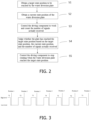
FIG. 2 is a flowchart showing steps of the control method for the water diversion device of the present disclosure; -
FIG. 3 is a schematic diagram showing signal distribution of the control method for the water diversion device of the present disclosure; -
FIG. 4 is a schematic structural diagram of a first embodiment of a position detection component of the water diversion device of the present disclosure; and -
FIG. 5 is a schematic structural diagram of a second embodiment of the position detection component of the water diversion device of the present disclosure. - 1: driving component; 11: rotating shaft; 2: water diversion cover; 21: water outlet; 3: water diversion plate; 31: through hole; 311: first through hole; 312: second through hole; 313: third through hole; 4: position detection component; 41: gear; 411: first gear tooth; 412: second gear tooth; 42: microswitch; 43: light emitting device; 44: light receiving device.
- Preferred embodiments of the present disclosure will be described below with reference to the accompanying drawings. It should be understood by those skilled in the art that these embodiments are only used to explain the technical principle of the present disclosure, and are not intended to limit the scope of protection of the present disclosure. Those skilled in the art can make adjustments to these embodiments as needed, so as to adapt to specific application scenes. For example, although the third preset time is larger than the first preset time in the description, it is obvious that the third preset time can be smaller than the first preset time in the description, as long as an initial position can be set for the purpose of distinguishing.
- As shown in
FIG. 1 , in order to solve the problem of poor control accuracy of the rotation position of thewater diversion plate 3 in the water diversion device of existing dishwashers, the water diversion device of the present disclosure includes: adriving component 1, on which arotating shaft 11 is arranged; awater diversion cover 2, on whichwater outlets 21 are arranged; awater diversion plate 3, which is connected with therotating shaft 11 and provided with throughholes 31, and which is communicated withdifferent water outlets 21 when thewater diversion plate 3 rotates to different state positions, so as to achieve switching of water path; and aposition detection component 4, which is arranged to send signals in a process of switching thewater diversion plate 3 between two of the state positions. In a possible embodiment, thedriving component 1 is a motor; specifically, it can be a DC motor or an AC motor, with at least one pole controllable to ensure that the motor can be powered on and off normally. - As shown in
FIG. 2 and with reference toFIG. 1 , the control method for the water diversion device of the present disclosure includes the following steps S1-S5. - Step S1: obtaining a target state position to be reached by the
water diversion plate 3. - During the operation of the dishwasher, in order to achieve a good washing effect, the
water diversion plate 3 will switch to different target state positions throughout the washing process to achieve switching of different water paths. Therefore, the control method for the water diversion device of the present disclosure first needs to determine the target state position to be reached, so as to realize precise control of the position. - Step S2: obtaining a current state position of the
water diversion plate 3. - The current state position of the
water diversion plate 3 includes a state position at which thewater diversion plate 3 finally stopped when it last rotated, or a state position when it was powered on. - Step S3: controlling the
driving component 1 to work and counting the number of signals actually received. - The above signals may take various forms, such as electrical signals, optical signals, or acoustic signals. In a preferred embodiment, the signals actually received are electrical signals, which include valid signals and invalid signals, that is, the numbers of received valid signals and invalid signals are counted respectively. Further, the valid signals are high-level signals with a continuous detection time larger than a first preset time, and the invalid signals are low-level signals with a continuous detection time larger than a second preset time. The first preset time is larger than the second preset time. For example, the first preset time is 300ms, and the second preset time is 10ms. Further, the valid signals include an initial position valid signal and a conventional position valid signal. The initial position valid signal is a high-level signal with a continuous detection time larger than a third preset time, and the conventional position valid signal is a high-level signal with a continuous detection time larger than the first preset time. The third preset time is larger than the first preset time. For example, the third preset time is 1000ms, and the first preset time is 300ms.
- In order to prevent interference, the present disclosure limits the continuous detection time of the high-level signals, and only when the continuous detection time is larger than the first preset time will the high-level signals be denoted as valid signals, that is, the counting of the number of valid signals begins; similarly, only when the continuous detection time is larger than the second preset time will the low-level signals be denoted as invalid signals. By extending the continuous detection time of the low-level signals, the continuous detection time of the low-level signals is made larger than the duration of a certain electromagnetic interference, which can effectively prevent misjudgment caused by electromagnetic interference during signal transmission, and avoid reduction in control accuracy. For example, low-level signals that were misjudged due to electromagnetic interference appear in the high-level signal segment. In the present application, high level means that the high-level signal has been continuously detected for more than 10ms. In a preferred embodiment, only when the continuous detection time is larger than the first preset time (such as 300ms) will the high-level signals be denoted as valid signals.
- Step S4: judging whether the
water diversion plate 3 has reached the target state position based on the target state position, the current state position, and the number of signals actually received. - Step S5: controlling the
driving component 1 to stop rotating when thewater diversion plate 3 reaches the target state position. - By judging the target state position and the current state position, and based on the number of signals actually received, it can be analyzed whether the
water diversion plate 3 has reached the target state position. In a preferred embodiment, a target number of signals received can be first determined based on the target state position and the current state position; then, based on the number of signals actually received and the target number of signals received, it can be judged whether thewater diversion plate 3 has reached the target state position. For example, as shown inFIG. 3 , if the current state position isposition 1 and the target state position isposition 4, it is necessary to continuously detect three high-level valid signals of T2, T3 and T4, and three low-level invalid signals. When the continuous detection time of the last low-level signal is more than 10ms, the low-level signal is denoted as an invalid signal. When a low-level invalid signal with the continuous detection time being more than 10ms is finally detected, thedriving component 1 is controlled to stop working; at this point,position 4 is reached, andposition 4 is used as an initial position for the next rotation of thewater diversion plate 3. If rotation toposition 2 is desired next time, then when four high-level valid signals of T5, T6, T1 and T2 and four low-level invalid signals are detected, thedriving component 1 is controlled to stop working. - In a possible embodiment, the numbers of valid signals and invalid signals Nx, x=a, b, c,..., at each state position can be set by taking the initial position as a reference, where Nx=1,..., m. If the number of signals at the current state position is Na, and the number of signals at the target state position is Nb, the target number of signals received is determined to be Nb-Na when Na<Nb, and the target number of signals received is determined to be m-Na+Nb when Na>Nb. For example, the numbers of valid signals and invalid signals at
position 2 are each set to 1, the numbers of valid signals and invalid signals atposition 3 are each set to 2, and so on. In this way, the numbers of valid signals and invalid signals at the target state position and the current state position can be obtained. For example, if the numbers of valid signals and invalid signals at the current state position are 2 respectively (i.e., position 3), and the numbers of valid signals and invalid signals at the target state position are 4 respectively (i.e., position 5), then fromposition 3 toposition 5, there are two valid signals and two invalid signals to go through. For another example, there are a total of six state positions, so m=6. If the numbers of valid signals and invalid signals at the current state position are 4 respectively (i.e., position 5), and the numbers of valid signals and invalid signals at the target state position are 1 respectively (i.e., position 2), then fromposition 5 toposition 2, there are 6-4+1=3 (three) valid signals and invalid signals to go through. - The above arrangement has the following advantages: the rotating
shaft 11 of thedriving component 1 of the present disclosure is directly connected to thewater diversion plate 3, thus avoiding transmission errors caused by gear transmission. Moreover, the state position of thewater diversion plate 3 is indirectly reflected by the number of signals, so that precise control of multiple state positions of thewater diversion plate 3 can be achieved, thereby ensuring the washing effect of the dishwasher. - In a preferred embodiment, the control method of the present disclosure further includes: controlling the
driving component 1 to work; judging whether the initial position valid signal and the invalid signals have been received in sequence; and if yes, controlling thedriving component 1 to stop working. - When the water diversion device works, the
water diversion plate 3 first reaches the initial position, and the initial position is used as a reference point. For example, each time the dishwasher is powered on or off, the position of thewater diversion plate 3 is adjusted so that it returns to the initial position. Alternatively, when the water diversion device initially works, the position of thewater diversion plate 3 is adjusted so that it returns to the initial position, that is, a "zeroing" operation is performed, which is advantageous for counting the numbers of valid signals and invalid signals. The water diversion device is reset when it initially works, and each time it is powered on subsequently, the last final working position can be used as the base point. - With continued reference to
FIG. 1 , the present disclosure also provides a water diversion device, which is the water diversion device described in the above technical solutions. In a preferred embodiment, thewater outlets 21 include a first water outlet, a second water outlet and a third water outlet; circle centers of the threewater outlets 21 are located on a same dividing circle, and an included angle between the circle centers of adjacent two of thewater outlets 21 is 120°; the throughholes 31 include a first throughhole 311, a second throughhole 312, and a third throughhole 313; circle centers of the first throughhole 311, the second throughhole 312 and the third throughhole 313 are located on a same dividing circle; an included angle between the circle centers of the first throughhole 311 and the second throughhole 312 is 120°, and an included angle between the second throughhole 312 and the third throughhole 313 is 60°. - The above arrangement has the following advantages: it can achieve water path control of six state positions, namely: the first water outlet is communicated, and the second water outlet and the third water outlet are closed; the second water outlet is communicated, and the first water outlet and the third water outlet are closed; the third water outlet is communicated, and the first water outlet and the second water outlet are closed; the first water outlet is closed, and the second water outlet and the third water outlet are opened; the second water outlet is closed, and the first water outlet and the third water outlet are opened; the third water outlet is closed, and the first water outlet and the second water outlet are opened. It can achieve switching of six different water paths, achieve good washing effect, and solve the pain point of users complaining that the dishwasher cannot achieve clean washing. In addition, the shape of the through
holes 31 and the shape of thewater outlets 21 of the present disclosure may take various forms, such as circular, elliptical, or irregular holes, so as to facilitate conducting corresponding design according to actual application scenes, making the application range wider. In a possible embodiment, the shape of the throughholes 31 is the same as that of thewater outlets 21. - As shown in
FIG. 4 and with continued reference toFIG. 1 , in a first possible embodiment, theposition detection component 4 includes agear 41 and amicroswitch 42; thegear 41 is connected with the rotatingshaft 11, and gear teeth of thegear 41 include afirst gear tooth 411 and multiplesecond gear teeth 412; a distance between thefirst gear tooth 411 and the adjacentsecond gear tooth 412 is smaller than a distance between other adjacent gear teeth, and at each of the state positions, the corresponding gear teeth come into contact with themicroswitch 42 to trigger a signal. It can be understood that the above adjacentsecond gear tooth 412 to thefirst gear tooth 411 is an adjacent gear tooth with the same rotation direction as thegear 41. The above arrangement can minimize the contact time between thefirst gear tooth 411 and themicroswitch 42, thus serving as the base point for determining the initial position. - In an alternative embodiment, the distance between the
first gear tooth 411 and the adjacentsecond gear tooth 412 is larger than the distance between other adjacent gear teeth. This alternative embodiment corresponds to the above control method for the water diversion device. This arrangement has the following advantages: by setting the maximum distance between the first gear tooth and adjacent gear tooth, the first gear tooth can be in contact with themicroswitch 42 for the longest time, so that the triggered valid signal has the longest duration. Therefore, it can be used as the base point for the initial position, facilitating counting the number of signals. - As shown in
FIG. 5 , in a second possible embodiment, theposition detection component 4 includes alight emitting device 43 and alight receiving device 44; thelight emitting device 43 includes a shell and a light emitting source, the light emitting source is arranged on therotating shaft 11, and the shell is connected with the rotatingshaft 11 and covers the light emitting source; the shell is provided with light transmission holes, and at each of the state positions, light emitted from the corresponding light transmission hole propagates to thelight receiving device 44. - The light coming from the light emitting source can be emitted outward through the light transmission holes on the shell, and as the rotating
shaft 11 rotates, at each of the state positions, thelight receiving device 44 can receive the optical signals emitted from the corresponding light transmission holes. Therefore, based on the number of optical signals actually received, and by determining the position of thewater diversion plate 3 based on the target state position and the current state position, precise control of the position can be achieved. - The present disclosure also provides a dishwasher (not shown), which includes a housing, a spray arm, and the water diversion device in the above technical solutions. In a preferred embodiment, the dishwasher further includes a spray arm seat, which is connected to the
water diversion cover 2; the spray arm is rotatably connected to the spray arm seat, and the spray arm is provided with a first water flow channel and a second water flow channel; the first water outlet is communicated with the first water flow channel through the spray arm seat, and the second water outlet is communicated with the second water flow channel through the spray arm seat; the first water flow channel is provided with a forward-rotation guidance tilt port, and the second water flow channel is provided with a reverse-rotation guidance tilt port. - In the present disclosure, the first water outlet is communicated with the first water flow channel of the spray arm, the second water outlet is communicated with the second water flow channel of the spray arm, and the forward-rotation guidance tilt port and reverse-rotation guidance tilt port are arranged, so that forward rotation and reverse rotation of the spray arm can be achieved. In a possible embodiment, the above spray arm is a bottom spray arm, which can better wash the tableware and achieve a better cleaning effect. Further, the third water outlet is communicated with a middle spray arm and a top spray arm of the dishwasher at the same time, and forward-rotation guidance tilt ports or reverse-rotation guidance tilt ports are arranged according to actual needs. Therefore, by controlling the communication state of the
water outlets 21, multiple spraying modes are achieved for the three spray arms, thus improving the cleaning rate of the dishwasher. For example, instate position 1, the bottom spray arm is in forward rotation; instate position 2, the bottom spray arm is in reverse rotation, and the middle spray arm and the top spray arm are in forward rotation; instate position 3, the bottom spray arm is in reverse rotation; instate position 4, the bottom spray arm, the middle spray arm and the top spray arm are in forward rotation; and instate position 5, the middle spray arm and the top spray arm are in forward rotation. The tableware can be flexibly sprayed and cleaned by switching between several state positions. - In summary, the control method for the water diversion device of the present disclosure can accurately control the position for the switching of multiple water paths of the
water diversion plate 3 by determining the numbers of valid signals and invalid signals. By extending the continuous detection time of high-level and low-level signals, it can effectively prevent misjudgment caused by interference. By setting the longest or shortest distance between certain two gear teeth of thegear 41, the initial position can be determined, facilitating counting the number of signals. - It should be noted that the above embodiments are only used to illustrate the principles of the present disclosure, and are not intended to limit the scope of protection of the present disclosure. Without deviating from the principles of the present disclosure, those skilled in the art can adjust the above structures so that the present disclosure can be applied in more specific application scenes.
- For example, in an alternative embodiment, the valid signals may be low-level signals with a continuous detection time larger than the third preset time, and the invalid signals may be high-level signals with a continuous detection time larger than a fourth preset time, all of which do not deviate from the principles of the present disclosure and therefore fall within the scope of protection of the present disclosure.
- For example, in another alternative embodiment, the third preset time may be smaller than the first preset time. For example, the continuous detection time of the initial position valid signal is 300ms, and the continuous detection time of the conventional position valid signal is 1000ms, as long as the initial position and the conventional position can be distinguished. These changes do not deviate from the principles of the present disclosure, and therefore will all fall within the scope of protection of the present disclosure.
- For example, in another alternative embodiment, the
position detection component 4 includes a light source transmitter and a light source receiver. The light source transmitter is located on the light source receiver, and a reflector is provided on therotating shaft 11. At each of the state positions, the light emitted from the light source transmitter is reflected onto the light source receiver through the corresponding reflector and will be counted as one signal, as long as signals can be sent in the process of switching thewater diversion plate 3 between two state positions. These changes do not deviate from the principles of the present disclosure, and therefore will all fall within the scope of protection of the present disclosure. - Finally, it should be noted that although the present disclosure is described by taking the dishwasher as an example, the water diversion device of the present disclosure can obviously be applied to other devices used for water path switching. For example, the water diversion device can also be applied in a water supply system and the like.
- It can be understood by those skilled in the art that the dishwasher described above also includes some other well-known structures, such as a processor, a controller, a memory, etc. The memory includes but is not limited to random access memory, flash memory, read-only memory, programmable read-only memory, volatile memory, non-volatile memory, serial memory, parallel memory or register, etc. The processor includes but is not limited to CPLD/FPGA, DSP, ARM processor, MIPS processor, etc. In order not to unnecessarily obscure the embodiments of the present disclosure, these well-known structures are not shown in the drawings.
- In the above embodiments, although the steps have been described in the order described above, it can be understood by those skilled in the art that in order to achieve the effects of the embodiments, different steps do not necessarily need to be executed in this order. They can be executed simultaneously (in parallel) or in a reverse order. For example, the current state position of the water diversion plate is obtained first, and then the target state position to be reached by the water diversion plate is obtained. These simple changes are all within the scope of protection of the present disclosure.
- Hitherto, the technical solutions of the present disclosure have been described in connection with the preferred embodiments shown in the accompanying drawings, but it is easily understood by those skilled in the art that the scope of protection of the present disclosure is obviously not limited to these specific embodiments. Without departing from the principles of the present disclosure, those skilled in the art can make equivalent changes or replacements to relevant technical features, and all the technical solutions after these changes or replacements will fall within the scope of protection of the present disclosure.
Claims (10)
- A control method for a water diversion device, wherein the water diversion device comprises:a driving component, on which a rotating shaft is arranged;a water diversion cover, on which water outlets are arranged;a water diversion plate, which is connected with the rotating shaft and provided with through holes, and which is communicated with different water outlets when the water diversion plate rotates to different state positions, so as to achieve switching of water path; anda position detection component, which is arranged to send signals in a process of switching the water diversion plate between two of the state positions;the control method comprises:obtaining a target state position to be reached by the water diversion plate;obtaining a current state position of the water diversion plate;controlling the driving component to work and counting the number of signals actually received;judging whether the water diversion plate has reached the target state position based on the target state position, the current state position, and the number of signals actually received; andcontrolling the driving component to stop rotating when the water diversion plate reaches the target state position.
- The control method for the water diversion device according to claim 1, wherein the signals comprise valid signals and invalid signals, and the step of "counting the number of signals actually received" further comprises:
respectively counting the numbers of the valid signals and the invalid signals received. - The control method for the water diversion device according to claim 2, wherein the valid signals are high-level signals with a duration larger than a first preset time, and the invalid signals are low-level signals with a duration larger than a second preset time.
- The control method for the water diversion device according to claim 3, wherein the valid signals comprise an initial position valid signal and a conventional position valid signal; the initial position valid signal is a high-level signal with a duration larger than a third preset time, and the conventional position valid signal is a high-level signal with the duration larger than the first preset time, wherein the third preset time is larger than the first preset time; and/or
the first preset time is larger than the second preset time. - The control method for the water diversion device according to claim 4, further comprising:controlling the driving component to work;judging whether the initial position valid signal and the invalid signals have been received in sequence; andif yes, controlling the driving component to stop working.
- The control method for the water diversion device according to claim 1, wherein the step of "judging whether the water diversion plate has reached the target state position based on the target state position, the current state position, and the number of signals actually received" further comprises:determining a target number of signals received based on the target state position and the current state position; andjudging whether the water diversion plate has reached the target state position based on the number of signals actually received and the target number of signals received.
- A water diversion device, comprising:a driving component, on which a rotating shaft is arranged;a water diversion cover, on which water outlets are arranged;a water diversion plate, which is connected with the rotating shaft and provided with through holes, and which is communicated with different water outlets when the water diversion plate rotates to different state positions, so as to achieve switching of water path; anda position detection component, which is arranged to send signals in a process of switching the water diversion plate between two of the state positions.
- The water diversion device according to claim 7, wherein the water outlets comprise a first water outlet, a second water outlet and a third water outlet; circle centers of the three water outlets are located on a same dividing circle, and an included angle between the circle centers of adjacent two of the water outlets is 120°; the through holes comprise a first through hole, a second through hole, and a third through hole; circle centers of the first through hole, the second through hole and the third through hole are located on a same dividing circle; an included angle between the circle centers of the first through hole and the second through hole is 120°, and an included angle between the second through hole and the third through hole is 60°; and/orthe position detection component comprises a gear and a microswitch; the gear is connected with the rotating shaft, and gear teeth of the gear comprise a first gear tooth and multiple second gear teeth; a distance between the first gear tooth and the adjacent second gear tooth is larger than a distance between other adjacent gear teeth, and at each of the state positions, the corresponding gear teeth come into contact with the microswitch to trigger a signal; orthe position detection component comprises a light emitting device and a light receiving device; the light emitting device comprises a shell and a light emitting source, the light emitting source is arranged on the rotating shaft, and the shell is connected with the rotating shaft and covers the light emitting source; the shell is provided with light transmission holes, and at each of the state positions, light emitted from the corresponding light transmission holes propagate to the light receiving device.
- A dishwasher, comprising a housing, a spray arm, and the water diversion device according to claim 7 or 8.
- The dishwasher according to claim 9 depending from claim 8, further comprising:a spray arm seat, which is connected to the water diversion cover;wherein the spray arm is rotatably connected to the spray arm seat, and the spray arm is provided with a first water flow channel and a second water flow channel; the first water outlet is communicated with the first water flow channel through the spray arm seat, and the second water outlet is communicated with the second water flow channel through the spray arm seat; the first water flow channel is provided with a forward-rotation guidance tilt port, and the second water flow channel is provided with a reverse-rotation guidance tilt port.
Applications Claiming Priority (2)
| Application Number | Priority Date | Filing Date | Title |
|---|---|---|---|
| CN202110191874.XA CN114947674A (en) | 2021-02-19 | 2021-02-19 | Control method of water distribution device, water distribution device and dish washing machine |
| PCT/CN2022/075391 WO2022174740A1 (en) | 2021-02-19 | 2022-02-07 | Control method for water diversion device, water diversion device and dishwasher |
Publications (4)
| Publication Number | Publication Date |
|---|---|
| EP4278944A1 true EP4278944A1 (en) | 2023-11-22 |
| EP4278944A4 EP4278944A4 (en) | 2024-07-17 |
| EP4278944C0 EP4278944C0 (en) | 2025-09-10 |
| EP4278944B1 EP4278944B1 (en) | 2025-09-10 |
Family
ID=82932073
Family Applications (1)
| Application Number | Title | Priority Date | Filing Date |
|---|---|---|---|
| EP22755513.3A Active EP4278944B1 (en) | 2021-02-19 | 2022-02-07 | Control method for water diversion device, water diversion device and dishwasher |
Country Status (4)
| Country | Link |
|---|---|
| US (1) | US12543917B2 (en) |
| EP (1) | EP4278944B1 (en) |
| CN (1) | CN114947674A (en) |
| WO (1) | WO2022174740A1 (en) |
Families Citing this family (1)
| Publication number | Priority date | Publication date | Assignee | Title |
|---|---|---|---|---|
| CN116570201A (en) * | 2023-05-11 | 2023-08-11 | 广东万和电气有限公司 | Method and device for resetting water diversion valve and dishwasher |
Family Cites Families (13)
| Publication number | Priority date | Publication date | Assignee | Title |
|---|---|---|---|---|
| DE10133130A1 (en) * | 2001-07-07 | 2003-01-16 | Miele & Cie | Circulation pump with/without heating device, especially for supplying washing liquid to dishwasher spray arms, has water switch integrated into circulation pump |
| DE102008016171A1 (en) * | 2008-03-28 | 2009-10-01 | BSH Bosch und Siemens Hausgeräte GmbH | Water-conducting household appliance |
| DE102010031235B4 (en) * | 2010-07-12 | 2016-07-21 | BSH Hausgeräte GmbH | household appliance |
| US9763552B2 (en) * | 2014-06-12 | 2017-09-19 | Haier Us Appliance Solutions, Inc. | Dishwasher diverter valves with continuous calibration |
| CN204542006U (en) * | 2015-03-19 | 2015-08-12 | 青岛海尔洗碗机有限公司 | A kind of dish-washing machine bifurcation structure and dish-washing machine |
| IT201700048530A1 (en) * | 2017-05-05 | 2018-11-05 | J P Ind S P A | Improved flow diverter for dishwashing machine or similar. |
| CN110495837B (en) * | 2018-05-17 | 2022-10-04 | 青岛海尔洗碗机有限公司 | Dishwasher water separator, dishwasher and control method thereof |
| CN110495841B (en) * | 2018-05-17 | 2022-10-04 | 青岛海尔洗碗机有限公司 | Water distribution device of dish washing machine, dish washing machine and control method of dish washing machine |
| CN110495828B (en) * | 2018-05-17 | 2022-10-04 | 青岛海尔洗碗机有限公司 | Dishwasher water separator, dishwasher and control method thereof |
| CN209564102U (en) * | 2019-01-17 | 2019-11-01 | 杭州老板电器股份有限公司 | Shunt valve and dish-washing machine |
| CN210643953U (en) * | 2019-04-30 | 2020-06-02 | 广东易得电器有限公司 | Water diversion device and dish washing machine |
| CN112674680B (en) * | 2019-10-18 | 2024-01-26 | 青岛海尔洗碗机有限公司 | A dishwasher with a water-dividing path detection function and a control method thereof |
| CN111012275B (en) * | 2019-12-24 | 2021-05-11 | 珠海格力电器股份有限公司 | Dish washer divides liquid device and dish washer |
-
2021
- 2021-02-19 CN CN202110191874.XA patent/CN114947674A/en active Pending
-
2022
- 2022-02-07 EP EP22755513.3A patent/EP4278944B1/en active Active
- 2022-02-07 US US18/546,993 patent/US12543917B2/en active Active
- 2022-02-07 WO PCT/CN2022/075391 patent/WO2022174740A1/en not_active Ceased
Also Published As
| Publication number | Publication date |
|---|---|
| CN114947674A (en) | 2022-08-30 |
| EP4278944A4 (en) | 2024-07-17 |
| WO2022174740A1 (en) | 2022-08-25 |
| EP4278944C0 (en) | 2025-09-10 |
| EP4278944B1 (en) | 2025-09-10 |
| US12543917B2 (en) | 2026-02-10 |
| US20240130600A1 (en) | 2024-04-25 |
| US20240225409A9 (en) | 2024-07-11 |
Similar Documents
| Publication | Publication Date | Title |
|---|---|---|
| US11633081B2 (en) | Dishwasher with image-based diagnostics | |
| US11766160B2 (en) | Dishwasher with image-based position sensor | |
| EP4278944B1 (en) | Control method for water diversion device, water diversion device and dishwasher | |
| US11877711B2 (en) | Dishwasher with image-based detergent sensing | |
| US20210093155A1 (en) | Dishwasher with image-based fluid condition sensing | |
| US11399690B2 (en) | Dishwasher with cam-based position sensor | |
| US5494062A (en) | Electromechanical controller for dishwasher with alternating flow | |
| BRPI0302846B1 (en) | apparatus and method for obtaining communication signals from equipment | |
| US12453453B2 (en) | Control method for layered washing in dishwasher and dishwasher | |
| CN100581082C (en) | Method and device for optical communication via a low intensity indicator in the device | |
| US7091932B2 (en) | Method and apparatus for independent control of low intensity indicators used for optical communication in an appliance | |
| CN112674680B (en) | A dishwasher with a water-dividing path detection function and a control method thereof | |
| US7280769B2 (en) | Method and apparatus for operating an optical receiver for low intensity optical communication in a high speed mode | |
| US20050025493A1 (en) | Method and apparatus for using a close proximity probe for optical communication with a device external to the probe | |
| CN224003203U (en) | Shunt valve structure and dish washer | |
| US7321732B2 (en) | Method and apparatus for improving noise immunity for low intensity optical communication | |
| CN114521853A (en) | Dish washing machine | |
| CN119878862A (en) | Water diversion valve structure, dish washer and control method | |
| CN114521854A (en) | Dish washing machine | |
| CN116115149B (en) | Cleaning apparatus and control method | |
| US20260102041A1 (en) | Dispensing cup monitoring for a dishwasher appliance | |
| CN121080874A (en) | Dish washer | |
| KR950008355B1 (en) | Washing or rinsing machines for crockery valve sensers | |
| AU2023443819A1 (en) | Dishwasher comprisng improved flow controllor assembly | |
| CN121971013A (en) | A dishwasher, a smart home system and a lighting control method |
Legal Events
| Date | Code | Title | Description |
|---|---|---|---|
| STAA | Information on the status of an ep patent application or granted ep patent |
Free format text: STATUS: THE INTERNATIONAL PUBLICATION HAS BEEN MADE |
|
| PUAI | Public reference made under article 153(3) epc to a published international application that has entered the european phase |
Free format text: ORIGINAL CODE: 0009012 |
|
| STAA | Information on the status of an ep patent application or granted ep patent |
Free format text: STATUS: REQUEST FOR EXAMINATION WAS MADE |
|
| 17P | Request for examination filed |
Effective date: 20230817 |
|
| AK | Designated contracting states |
Kind code of ref document: A1 Designated state(s): AL AT BE BG CH CY CZ DE DK EE ES FI FR GB GR HR HU IE IS IT LI LT LU LV MC MK MT NL NO PL PT RO RS SE SI SK SM TR |
|
| DAV | Request for validation of the european patent (deleted) | ||
| DAX | Request for extension of the european patent (deleted) | ||
| A4 | Supplementary search report drawn up and despatched |
Effective date: 20240619 |
|
| RIC1 | Information provided on ipc code assigned before grant |
Ipc: A47L 15/42 20060101AFI20240613BHEP |
|
| STAA | Information on the status of an ep patent application or granted ep patent |
Free format text: STATUS: EXAMINATION IS IN PROGRESS |
|
| 17Q | First examination report despatched |
Effective date: 20240729 |
|
| GRAP | Despatch of communication of intention to grant a patent |
Free format text: ORIGINAL CODE: EPIDOSNIGR1 |
|
| STAA | Information on the status of an ep patent application or granted ep patent |
Free format text: STATUS: GRANT OF PATENT IS INTENDED |
|
| INTG | Intention to grant announced |
Effective date: 20250422 |
|
| GRAS | Grant fee paid |
Free format text: ORIGINAL CODE: EPIDOSNIGR3 |
|
| GRAA | (expected) grant |
Free format text: ORIGINAL CODE: 0009210 |
|
| STAA | Information on the status of an ep patent application or granted ep patent |
Free format text: STATUS: THE PATENT HAS BEEN GRANTED |
|
| AK | Designated contracting states |
Kind code of ref document: B1 Designated state(s): AL AT BE BG CH CY CZ DE DK EE ES FI FR GB GR HR HU IE IS IT LI LT LU LV MC MK MT NL NO PL PT RO RS SE SI SK SM TR |
|
| REG | Reference to a national code |
Ref country code: GB Ref legal event code: FG4D |
|
| REG | Reference to a national code |
Ref country code: CH Ref legal event code: EP |
|
| REG | Reference to a national code |
Ref country code: DE Ref legal event code: R096 Ref document number: 602022021256 Country of ref document: DE |
|
| REG | Reference to a national code |
Ref country code: IE Ref legal event code: FG4D |
|
| U01 | Request for unitary effect filed |
Effective date: 20251001 |
|
| U07 | Unitary effect registered |
Designated state(s): AT BE BG DE DK EE FI FR IT LT LU LV MT NL PT RO SE SI Effective date: 20251010 |
|
| PG25 | Lapsed in a contracting state [announced via postgrant information from national office to epo] |
Ref country code: NO Free format text: LAPSE BECAUSE OF FAILURE TO SUBMIT A TRANSLATION OF THE DESCRIPTION OR TO PAY THE FEE WITHIN THE PRESCRIBED TIME-LIMIT Effective date: 20251210 |
|
| PG25 | Lapsed in a contracting state [announced via postgrant information from national office to epo] |
Ref country code: HR Free format text: LAPSE BECAUSE OF FAILURE TO SUBMIT A TRANSLATION OF THE DESCRIPTION OR TO PAY THE FEE WITHIN THE PRESCRIBED TIME-LIMIT Effective date: 20250910 |
|
| PG25 | Lapsed in a contracting state [announced via postgrant information from national office to epo] |
Ref country code: GR Free format text: LAPSE BECAUSE OF FAILURE TO SUBMIT A TRANSLATION OF THE DESCRIPTION OR TO PAY THE FEE WITHIN THE PRESCRIBED TIME-LIMIT Effective date: 20251211 |
|
| PG25 | Lapsed in a contracting state [announced via postgrant information from national office to epo] |
Ref country code: PL Free format text: LAPSE BECAUSE OF FAILURE TO SUBMIT A TRANSLATION OF THE DESCRIPTION OR TO PAY THE FEE WITHIN THE PRESCRIBED TIME-LIMIT Effective date: 20250910 |
|
| PG25 | Lapsed in a contracting state [announced via postgrant information from national office to epo] |
Ref country code: RS Free format text: LAPSE BECAUSE OF FAILURE TO SUBMIT A TRANSLATION OF THE DESCRIPTION OR TO PAY THE FEE WITHIN THE PRESCRIBED TIME-LIMIT Effective date: 20251210 |
|
| PG25 | Lapsed in a contracting state [announced via postgrant information from national office to epo] |
Ref country code: ES Free format text: LAPSE BECAUSE OF FAILURE TO SUBMIT A TRANSLATION OF THE DESCRIPTION OR TO PAY THE FEE WITHIN THE PRESCRIBED TIME-LIMIT Effective date: 20250910 |
|
| U20 | Renewal fee for the european patent with unitary effect paid |
Year of fee payment: 5 Effective date: 20260225 |
|
| PG25 | Lapsed in a contracting state [announced via postgrant information from national office to epo] |
Ref country code: SM Free format text: LAPSE BECAUSE OF FAILURE TO SUBMIT A TRANSLATION OF THE DESCRIPTION OR TO PAY THE FEE WITHIN THE PRESCRIBED TIME-LIMIT Effective date: 20250910 |
|
| PG25 | Lapsed in a contracting state [announced via postgrant information from national office to epo] |
Ref country code: IS Free format text: LAPSE BECAUSE OF FAILURE TO SUBMIT A TRANSLATION OF THE DESCRIPTION OR TO PAY THE FEE WITHIN THE PRESCRIBED TIME-LIMIT Effective date: 20260110 |
|
| PG25 | Lapsed in a contracting state [announced via postgrant information from national office to epo] |
Ref country code: CZ Free format text: LAPSE BECAUSE OF FAILURE TO SUBMIT A TRANSLATION OF THE DESCRIPTION OR TO PAY THE FEE WITHIN THE PRESCRIBED TIME-LIMIT Effective date: 20250910 |
|
| PG25 | Lapsed in a contracting state [announced via postgrant information from national office to epo] |
Ref country code: SK Free format text: LAPSE BECAUSE OF FAILURE TO SUBMIT A TRANSLATION OF THE DESCRIPTION OR TO PAY THE FEE WITHIN THE PRESCRIBED TIME-LIMIT Effective date: 20250910 |
|
| PLBE | No opposition filed within time limit |
Free format text: ORIGINAL CODE: 0009261 |
|
| STAA | Information on the status of an ep patent application or granted ep patent |
Free format text: STATUS: NO OPPOSITION FILED WITHIN TIME LIMIT |
|
| REG | Reference to a national code |
Ref country code: CH Ref legal event code: L10 Free format text: ST27 STATUS EVENT CODE: U-0-0-L10-L00 (AS PROVIDED BY THE NATIONAL OFFICE) Effective date: 20260722 |