EP4278876A2 - Method and system for precise planting based on planned paths - Google Patents
Method and system for precise planting based on planned paths Download PDFInfo
- Publication number
- EP4278876A2 EP4278876A2 EP23160059.4A EP23160059A EP4278876A2 EP 4278876 A2 EP4278876 A2 EP 4278876A2 EP 23160059 A EP23160059 A EP 23160059A EP 4278876 A2 EP4278876 A2 EP 4278876A2
- Authority
- EP
- European Patent Office
- Prior art keywords
- path
- exclusion zone
- implement
- vehicle
- planter
- Prior art date
- Legal status (The legal status is an assumption and is not a legal conclusion. Google has not performed a legal analysis and makes no representation as to the accuracy of the status listed.)
- Granted
Links
Images




Classifications
-
- A—HUMAN NECESSITIES
- A01—AGRICULTURE; FORESTRY; ANIMAL HUSBANDRY; HUNTING; TRAPPING; FISHING
- A01B—SOIL WORKING IN AGRICULTURE OR FORESTRY; PARTS, DETAILS, OR ACCESSORIES OF AGRICULTURAL MACHINES OR IMPLEMENTS, IN GENERAL
- A01B79/00—Methods for working soil
- A01B79/02—Methods for working soil combined with other agricultural processing, e.g. fertilising, planting
-
- A—HUMAN NECESSITIES
- A01—AGRICULTURE; FORESTRY; ANIMAL HUSBANDRY; HUNTING; TRAPPING; FISHING
- A01B—SOIL WORKING IN AGRICULTURE OR FORESTRY; PARTS, DETAILS, OR ACCESSORIES OF AGRICULTURAL MACHINES OR IMPLEMENTS, IN GENERAL
- A01B69/00—Steering of agricultural machines or implements; Guiding agricultural machines or implements on a desired track
- A01B69/007—Steering or guiding of agricultural vehicles, e.g. steering of the tractor to keep the plough in the furrow
- A01B69/008—Steering or guiding of agricultural vehicles, e.g. steering of the tractor to keep the plough in the furrow automatic
-
- A—HUMAN NECESSITIES
- A01—AGRICULTURE; FORESTRY; ANIMAL HUSBANDRY; HUNTING; TRAPPING; FISHING
- A01B—SOIL WORKING IN AGRICULTURE OR FORESTRY; PARTS, DETAILS, OR ACCESSORIES OF AGRICULTURAL MACHINES OR IMPLEMENTS, IN GENERAL
- A01B79/00—Methods for working soil
- A01B79/005—Precision agriculture
-
- A—HUMAN NECESSITIES
- A01—AGRICULTURE; FORESTRY; ANIMAL HUSBANDRY; HUNTING; TRAPPING; FISHING
- A01C—PLANTING; SOWING; FERTILISING
- A01C21/00—Methods of fertilising, sowing or planting
- A01C21/005—Following a specific plan, e.g. pattern
-
- G—PHYSICS
- G01—MEASURING; TESTING
- G01S—RADIO DIRECTION-FINDING; RADIO NAVIGATION; DETERMINING DISTANCE OR VELOCITY BY USE OF RADIO WAVES; LOCATING OR PRESENCE-DETECTING BY USE OF THE REFLECTION OR RERADIATION OF RADIO WAVES; ANALOGOUS ARRANGEMENTS USING OTHER WAVES
- G01S19/00—Satellite radio beacon positioning systems; Determining position, velocity or attitude using signals transmitted by such systems
- G01S19/01—Satellite radio beacon positioning systems transmitting time-stamped messages, e.g. GPS [Global Positioning System], GLONASS [Global Orbiting Navigation Satellite System] or GALILEO
- G01S19/13—Receivers
- G01S19/23—Testing, monitoring, correcting or calibrating of receiver elements
-
- G—PHYSICS
- G05—CONTROLLING; REGULATING
- G05D—SYSTEMS FOR CONTROLLING OR REGULATING NON-ELECTRIC VARIABLES
- G05D1/00—Control of position, course, altitude or attitude of land, water, air or space vehicles, e.g. using automatic pilots
- G05D1/02—Control of position or course in two dimensions
- G05D1/021—Control of position or course in two dimensions specially adapted to land vehicles
- G05D1/0212—Control of position or course in two dimensions specially adapted to land vehicles with means for defining a desired trajectory
- G05D1/0219—Control of position or course in two dimensions specially adapted to land vehicles with means for defining a desired trajectory ensuring the processing of the whole working surface
-
- G—PHYSICS
- G05—CONTROLLING; REGULATING
- G05D—SYSTEMS FOR CONTROLLING OR REGULATING NON-ELECTRIC VARIABLES
- G05D1/00—Control of position, course, altitude or attitude of land, water, air or space vehicles, e.g. using automatic pilots
- G05D1/02—Control of position or course in two dimensions
- G05D1/021—Control of position or course in two dimensions specially adapted to land vehicles
- G05D1/0268—Control of position or course in two dimensions specially adapted to land vehicles using internal positioning means
- G05D1/027—Control of position or course in two dimensions specially adapted to land vehicles using internal positioning means comprising intertial navigation means, e.g. azimuth detector
-
- A—HUMAN NECESSITIES
- A01—AGRICULTURE; FORESTRY; ANIMAL HUSBANDRY; HUNTING; TRAPPING; FISHING
- A01B—SOIL WORKING IN AGRICULTURE OR FORESTRY; PARTS, DETAILS, OR ACCESSORIES OF AGRICULTURAL MACHINES OR IMPLEMENTS, IN GENERAL
- A01B63/00—Lifting or adjusting devices or arrangements for agricultural machines or implements
- A01B63/14—Lifting or adjusting devices or arrangements for agricultural machines or implements for implements drawn by animals or tractors
- A01B63/24—Tools or tool-holders adjustable relatively to the frame
- A01B63/32—Tools or tool-holders adjustable relatively to the frame operated by hydraulic or pneumatic means without automatic control
-
- A—HUMAN NECESSITIES
- A01—AGRICULTURE; FORESTRY; ANIMAL HUSBANDRY; HUNTING; TRAPPING; FISHING
- A01C—PLANTING; SOWING; FERTILISING
- A01C7/00—Sowing
- A01C7/08—Broadcast seeders; Seeders depositing seeds in rows
- A01C7/10—Devices for adjusting the seed-box ; Regulation of machines for depositing quantities at intervals
- A01C7/102—Regulating or controlling the seed rate
Definitions
- This disclosure relates to a method and system for precise planting based on planned paths.
- a planter can control selectively the row units of an implement, such as a planter.
- an automatic guidance system may be used to guide a vehicle, or its implement to track a path plan.
- previous planting paths of an implement during the same season may interfere with subsequent planting paths of the implement during the same season, which can reduce crop yields and waste crop inputs, like seeds.
- a buffer zone or headlands region around the field could be left unplanted to reduce such interferences albeit with a potential yield penalty for the unplanted buffer zone.
- a method and system for precise planting based on planned paths e.g., to efficiently use crop inputs for maximum potential yield).
- a method and system facilitates precise planting based on planned paths.
- a path planning module or electronic data processor is configured to establish a path plan for an implement (e.g., planter) to cover a first area of the field at least once with a sequence of path segments in which some path segments are generally parallel to each other and spaced apart.
- a path interference estimator or the electronic data processor is configured to estimate potential interference between two or more path segments with respect to a first path segment and a second path segment, wherein the first path segment is associated with an earlier scheduled portion of the sequence and the second path segment is associated with a later scheduled portion of the sequence.
- An exclusion zone module or the electronic data processor is configured to determine an exclusion zone for the implement (e.g., row units of a planter) to prohibit planting of one or more rows of seeds or seedlings within the exclusion zone based on the estimated potential interference. Responsive to user input via the user interface, the electronic data processor is configured to activate or execute the path plan and determined exclusion zone in accordance with the established path plan and determined exclusion zone.
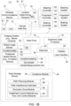
- FIG. 1A is one embodiment of a block diagram of a system 11 for determining a path plan for an off-road vehicle (e.g., 82 in FIG. 4 ) to control an implement (e.g., 83 in FIG. 4 ).
- the system 11 is capable of detecting motion data and attitude data by one or more sensors, such as one or more location-determining receivers (10, 210), one or more accelerometers (54, 56), gyroscope 55, or an internal measurement unit (IMU) (53, 153) that use accelerometers or gyroscopes.
- sensors such as one or more location-determining receivers (10, 210), one or more accelerometers (54, 56), gyroscope 55, or an internal measurement unit (IMU) (53, 153) that use accelerometers or gyroscopes.
- IMU internal measurement unit
- the system 11 may send a path plan or data message to an operator or end user of the detection system 11 via a wireless communications channel and via a user interface 22 that is incorporated into a vehicle, such as a display 25.
- a user interface 22 and display 25 may be located remotely from the vehicle via a wireless link to support remote control or tele-operation of the vehicle by the operator.
- the system 11 comprises an electronic data processing system 14 that is coupled to a location-determining receiver 10 directly, or via a vehicle data bus 12.
- vehicle data bus 12 The optional connection via vehicle data bus 12 is shown in dashed lines because it is optional and the connection between the electronic data processing system 14 and location-determining receiver 10 may be direct, as indicated by transmission line 13, which can be used separately or cumulatively with the interconnection via the vehicle data bus 12.
- the location-determining receiver 10 may have an antenna 81 mounted on the vehicle, on the implement or both.
- a first location-determining receiver 10 and its antenna 81 are on or in the vehicle (e.g., 82 in FIG. 2 ); a second location-determining receiver 210 (in FIG. 1B ) and its antenna are on or in the implement (e.g., 83 in FIG. 2 ), where both the first location-determining receiver 10 and the second-location determining receiver 210 may comprise satellite navigation receivers (with or without differential correction data) or other location-determining receivers.
- the electronic data processing system 14 comprises an electronic data processor 18, one or more data ports 16, a user interface 22 and a data storage device 24 coupled to a data bus 20.
- the electronic data processor 18 may comprise a processor, a microcontroller, a digital signal processor, an application specific integrated circuit (ASIC), a programmable logic array, a programmable logic device, a logic circuit, an arithmetic logic unit, a Boolean logic device, or another data processing device.
- the data storage device 24 may comprise one or more of the following: electronic memory, nonvolatile electronic memory, an optical data storage device, a magnetic data storage device, or other device for storing digital or analog data.
- the data storage device 24 may store, retrieve, read and write one or more of the following items: a guidance module 26, a path planning module 57, a path interference estimator 58, an exclusion zone module 59, and an implement control module 60 (e.g., row unit control module).
- a module means software, electronics, or both, where software can include software instructions, executable files, data structures, and libraries, among other things.
- configured to, adapted to and arranged to may refer any of the following items: (1) software or program instructions that are stored in the data storage device 24 or other data storage and executable by the data processor 18 to perform certain functions, software, (2) software or embedded firmware that are stored in the location-determining receiver (10, 210) or its memory or data storage to perform certain functions, or (3) electronic, electrical circuits or modules that can perform substantially equivalent functions to the software, embedded firmware or program instructions.
- Any data port 16 may comprise a data transceiver, buffer memory, or both.
- the user interface 22 may comprise one or more of the following: a display 25 (e.g., display), a touch screen display, a keypad, a keyboard, a control panel, a pointing device (e.g., electronic mouse), or another device for entry or output of data from the data processing system 14.
- a wheel angle sensor 51, one or more accelerometers (54, 56), a rotational speed sensor 52, an optional IMU (53, 153) and a data bus 20 are coupled to the data ports 16.
- the electronic data processing system 14 communicates to data ports 16 directly, or indirectly via the data bus 20.
- the data ports 16 support the communication of data messages to, from or between, or among any of the following: the electronic data processor 18, the data storage device 24, any modules, data, files, libraries, or software within the data storage device 24, the location-determining receiver (10, 210) the wheel angle sensor 51, one or more accelerometers (54, 56), a rotational speed sensor 52, an optional IMU and a data bus 20.
- the optional IMU 53 is a separate device, whereas in other embodiments, the IMU 153 is integral with the location-determining receiver 10.
- the optional separate IMU 53 comprises one or more accelerometers 54 and a gyroscope 55, where the accelerometers 54 may be arranged on orthogonal axes with respect to each other to facilitate detection of vehicle attitude, such as roll angle, pitch angle and yaw angle of a vehicle.
- the steering controller 40, the propulsion controller 44 and the braking controller 48 are coupled to the vehicle data bus 12.
- the data processing system 14 can communicate with the steering controller 40, the propulsion controller 44 and the braking controller 48, and vice versa.
- the steering controller 40 is coupled to the steering system 42, such as an electrical motor or electrohydraulic device that is mechanically coupled to a steering mechanism (e.g., rack-and-pinion or Ackerman steering system) for controlling the angular orientation of one or more wheels about a generally vertical axis.
- the propulsion controller 44 may comprise an electronic engine controller for controlling a throttle or fuel metering system of a propulsion system 46, such as internal combustion engine.
- a propulsion controller 44 may comprise an inverter or motor controller for controlling a propulsion system 46, such as a drive motor of a hybrid or electric vehicle.
- the braking controller 48 interfaces with a braking system 50, such as hydraulic braking system, an electrohydraulic braking system, a cable braking system, or an electromechanical braking system to stop or decelerate the vehicle.
- the guidance module 26 controls the vehicle to track or follow a path plan, a planned path, such as sequence of one or more interconnected path segments, where one or more path segments may comprise any of the following: generally straight path segments, curved path segments, arced path segments, or otherwise.
- a guidance module 26 or path planning module 57 is configured to execute or process a previous or prior path segment before execution or processing of a present, subsequent or later path segment.
- a path plan may comprise a generally linear path plan, a curved path plan, a contour path plan, a spiral path plan, a coverage area path plan, or other path plan,
- a path plan may comprise any of the following: one or more linear path segments or rows, curved path segments or turns, such as an end turn, a key-hole end turn, a loop end turn, a row-skipping end turn.
- the guidance module 26 can control the steering, propulsion, and braking of the vehicle.
- the guidance module 26 can communicate with one or more of the following controllers to direct and guide the vehicle: steering controller 40, propulsion controller 44 and braking controller 48.
- the system 11 comprises one or more location-determining receivers (10, 210) for estimating a position, motion, and attitude data of the vehicle (82 in FIG. 2 ), or its implement (e.g., 83 in FIG. 2 ), or both.
- attitude refers to roll angle, pitch angle and yaw angle, or motion data associated with roll angle, pitch angle and yaw angle.
- motion data comprises velocity data (e.g., speed data), acceleration data, or both.
- the velocity data and acceleration data may be expressed as vectors.
- a yaw angle or heading can refer to: (1) an angular direction of travel of the vehicle with reference to due North or magnetic North, or (2) a yaw or yaw angle of the vehicle with reference to coordinate system, such as a Cartesian coordinate system.
- a first location-determining receiver 10 or its antenna 81 is mounted on the vehicle for estimating a position, motion or attitude data of the vehicle (82 in FIG. 4 ) and a second location-determining receiver 210 is mounted on the implement (e.g., 83 in FIG. 2 ) for estimating a position, motion or attitude data of the implement that is coupled to the vehicle; position, motion and attitude data is available for the vehicle, its implement or both for processing by the electronic data processor 18 to execute the software instructions associated with modules, estimators, or other components within the data storage device 24.
- the location-determining receiver (10, 210) (e.g., satellite navigation receiver), alone or together with a wireless communications device, has a pair of antennas 81 that are spaced apart with a known orientation. Further, the location-determining receiver (10, 210) or the electronic data processor 18 can couple (e.g., selectively or switchably in rapid succession during the same epoch) either antenna 81 of the pair of antennas 81 to support estimation of the attitude of the pair of antennas when the vehicle or implement is at a fixed position or substantially the same position.
- the location-determining receiver (10, 210) e.g., satellite navigation receiver
- the electronic data processor 18 can couple (e.g., selectively or switchably in rapid succession during the same epoch) either antenna 81 of the pair of antennas 81 to support estimation of the attitude of the pair of antennas when the vehicle or implement is at a fixed position or substantially the same position.
- the pair of antennas 81 are spaced apart by a known distance on an axis with a known or fixed orientation (e.g., compound angular offset in one or more dimensions) to the longitudinal axis (in the direction of travel of the vehicle) and vertical axis of the vehicle.
- the location-determining receiver (10, 210) may estimate a first position (e.g., in three dimensions) of the first antenna 81 and a second position (e.g., in three dimensions) of the second antenna 81.
- the data processor or the location-determining receiver (10, 210) may estimate the precise attitude (e.g., yaw data, roll data, or both) of the vehicle, or its implement, based on the first position and the second position for the same epoch or measurement period, with or without augmentation by the correction data.
- the precise attitude e.g., yaw data, roll data, or both
- a wireless communications device (47, 147) is coupled to a data port of a location-determining receiver (10, 210) or a vehicle data bus 12 to augment the received satellite signals and associated carrier phase measurements of the received satellite signals (e.g., of at least four satellites) at the location-determining receiver (10, 210).
- the wireless communications device (47, 147) may comprise a separate receiver or transceiver (e.g., satellite, cellular, or wireless device) may receive the correction data or differential correction data via a wireless signal transmitted from a satellite or a terrestrial base station (e.g., real-time kinematic (RTK) base station).
- RTK real-time kinematic
- the wireless communications device (47, 147) may receive correction data from one or more of the following sources of correction data: (a) differential correction data from local base stations or local reference receivers operating in a real-time-kinematic (RTK) mode, (b) correction data associated with a precise-point-position (PPP) satellite navigation system with precise orbital correction data for satellites and satellite clocks in a PPP mode, (c) correction data applicable to a satellite navigation system, and correction data (e.g., carrier-phase offset or position vector offset) provided from a hub or central processing center in communication a network of reference satellite navigation receivers, and (d) other correction data is commercially available from local, wide-area, regional, or global correction or satellite data augmentation services.
- RTK real-time-kinematic
- the location-determining receiver (10, 210) provides one or more of the following types of data for a vehicle, and/or its implement: yaw data (e.g., heading data), roll data, pitch data, position data, velocity data, and acceleration data (e.g., as vectors or in two or three dimensional coordinates).
- the location-determining receiver (10, 210) may comprise a satellite navigation receiver, a Global Navigation Satellite System (GNSS) receiver, a Global Positioning System (GPS) receiver, or another receiver for determining position data, motion data or attitude data.
- GNSS Global Navigation Satellite System
- GPS Global Positioning System
- a location-determining receiver (10, 210) provides location data, path heading data, vehicle heading data, velocity data, and acceleration data along target path or path plan to the data processing system 14 or guidance module 26.
- an optional separate inertial measurement unit 53 may be separate from the location-determining receiver 10 or an optional integral IMU 153 may be integrated with the location determining receiver 10.
- the optional nature of the separate IMU 53 and the integral IMU 153 is indicated by dashed lines in FIG. 1A .
- the separate IMU 53 or the integral IMU 153 can estimate the attitude, yaw angle, yaw rate, roll, roll rate, pitch angle, pitch rate for the vehicle, or its implement, for instance.
- the yaw rate may refer to yaw angular velocity, yaw angular acceleration or both; the roll rate may refer to roll angular velocity, roll angular acceleration or both; the pitch rate may refer to pitch angular velocity, pitch angular acceleration or both.
- the data processing system 14 comprises a roll sensor, pitch sensor and a yaw sensor.
- Any roll sensor, pitch sensor and yaw sensor may comprise an accelerometer (e.g., 54, 56), a three-axis accelerometer, a gyroscope, an IMU, or another sensor.
- each sensor, such as roll sensor which is based on accelerometer measurements and/or gyroscope measurements, is subject to bias in their measurements that may arise over time, unless the sensor is calibrated or recalibrated (e.g., by the carrier phase measurements of the location-determining receiver (10, 210).)
- the roll sensor comprises a first accelerometer 56 that is configured to measure roll angle, roll angular velocity, and/or roll angular acceleration of the vehicle.
- the pitch sensor comprises a second accelerometer 156 that is configured to measure pitch angle, pitch angular velocity and/or pitch angular acceleration of the vehicle.
- the roll sensor and the pitch sensor may provide attitude data and motion data, such as roll data and pitch data, that the electronic data processor 18 can use to determine a surface roughness estimate.
- the accelerometers (56, 156), gyroscopes 55 or IMU (53, 153) of the data processing system 14 detect or measure one or more of the following: pitch angle, pitch motion data, roll angle and roll motion data.
- a motion sensor is configured to detect motion data of an off-road vehicle traversing a field or work site during a sampling interval.
- the motion data comprises ground speed or velocity of the off-road vehicle, or its implement.
- a first sensor e.g., accelerometer 56 or IMU (53, 153)
- IMU IMU
- a second sensor (e.g., accelerometer 156 or IMU (53, 153)) is configured to: (a) detect roll data of the off-road vehicle, or its implement, for the sampling interval to obtain a roll acceleration, or (b) detect roll angular acceleration data of the off-road vehicle, or its implement, for the sampling interval. If the first sensor only detects pitch angle with respect to time, the electronic data processor 18 is configured to derive the pitch angle acceleration from a derivative of the detected pitch angle with respect to time. Similarly, if the second sensor only detects roll angle with respect to time, an electronic data processor 18 is configured to derive the roll angle acceleration from a derivative of the detected roll angle with respect to time.
- a rotational speed sensor 52 is configured to measure a drivetrain-derived wheel speed.
- the electronic data processor 18 or a path planning module 57 is configured to determine a path plan, such as prior path plan comprising one or more prior path segments and later path plan comprising one or more later path segments.
- the exclusion zone module 59 may be configured to estimate exclusion points or exclusion zones (e.g., cells) with reference to the path plan, planned paths or any constituent prior path segments, later path segments or both, as a vehicle (e.g., 82 in FIG. 2 ) prepares to traverse or traverses the field or work site over multiple sampling intervals.
- An electronic data processor 18 or path planning module 57 is configured to generate a graphical display 25 that illustrates one or more estimated zones (e.g., exclusions zones 104 or exclusion points 110) of corresponding path plan within the field or work site. Further, an end user interface 22 is adapted to display 25 the graphical display 25 to a user or operator of the vehicle. In some configurations, the graphical display that illustrates proposed, candidate or existing path plans and exclusion zones (e.g., 104) for the vehicle 82 and/or implement 83, although graphical representations fall within the scope of the disclosure and appended claims.
- a location-determining receiver (10, 210) can determine a position of a vehicle (82), or its implement (83), in the field or in the work site with respect to the estimated zones, such as headland regions of a field, a central region of a field, exclusion zones and exclusion points along a path plan or path segment.
- the exclusion zone module 59 can be operated in accordance with various techniques, which may be applied separately or cumulatively. Under a first technique, an exclusion zone module 59 is configured to estimate exclusion-zone settings (e.g., target exclusion-zone settings) for the implement 83 consistent with alignment and/or overlap of the determined position (e.g., in two or three dimensional coordinates) of the implement 83 (or vehicle 82) and the estimated exclusion zones 104 or exclusion points 110.
- exclusion-zone settings e.g., target exclusion-zone settings
- an exclusion zone module 59 configured to estimate exclusion-zone settings (e.g., target exclusion-zone settings) associated with the corresponding row units 66 of the implement 83 consistent with alignment and/or overlap of the determined position of the implement 83 and the estimated exclusion zones 104 or exclusion points 110, where different row units 66 can have different exclusion-zone settings if the different row units 66 of the implement fall within different estimated exclusion-zones of the corresponding exclusion zone ranges.
- exclusion-zone settings e.g., target exclusion-zone settings
- the implement control module 60 or actuator controller 63 can be operated in accordance with various procedures that may be applied separately or cumulatively. Under a first procedure, an implement control module 60, the actuator controller 63, or both are configured to control an actuator (71, 72) (e.g., via an interface (64, 65)) to adjust the estimated down-force setting for corresponding zones.
- an implement control module 60, actuator controller 63, or both are configured to control an actuator (71, 72) (e.g., via an interface 64, 65) to increase or increment the down-force setting for a primary corresponding zones of a field, or to decrease or decrement the down-force setting for a secondary corresponding zones of a field to transition between different down-force settings.
- the system 111 of FIG. 1B is similar to the system 11 of FIG. 1A , except the system 111 further comprises an imaging system 61, a second location determining receiver 210, a wireless communications device 147. As illustrated the imaging system 61 is coupled to one or more data ports 16 of the data processing system 14. Like reference numbers in FIG. 1A and FIG. 1B indicate like features or elements.
- the imaging system 61 is configured to collect image data of the field or work site in a forward field of view of the vehicle in one or more electromagnetic frequency bands or wavelengths, such as humanly visible light, infra-red radiation, ultra-violet radiation, or the like.
- the imaging system 61 may comprise a stereo imaging system or stereo camera for collecting stereoscopic images or three-dimensional image clouds or three-dimensional image constellations of ground regions within the field of view (e.g., forward facing region or zone in front of the vehicle 82).
- the imaging system 61 or electronic data processor 18 can align (e.g., or stitch together) successive local images to assemble an aggregate view of an entire field or work area that is traversed or surveyed by the off-road vehicle equipped with the imaging system 61.
- the imaging system 61 or electronic data processor 18 may assign or identify two or three dimensional reference points in successive local images to spatially align successive images to assemble an aggregate view of an entire field or work area.
- the second location-determining receiver 210 is the same or similar to the location-determining receiver 10, which may be referred to as the first location determining receiver. However, the first location-determining receiver 10 may be mounted on or in the vehicle 82, or its implement 83. If both a first location-determining receiver 10 and second location-determining receiver 210 are present, the second location-determining receiver 210 is typically mounted on or in the implement 83 and the first location-determining receiver 10 is mounted on or in the vehicle 82.
- the wireless communications device 147 is the same or similar to the wireless communications device 47. For example, the wireless communications device 147 is coupled to the second location-determining receiver 210 to provide correction data to it.
- a method and system facilitates precise planting based on planned paths, consistent with exclusion points 110 or exclusion zones 104 along paths where seeds are not planted for one or more row units 66 to reduce potential damage to previously planted seeds or seedlings near or within the exclusion points 110 or exclusion zones 104.
- the system comprises an electronic data processor 18 is coupled to data storage device 24 for storing one or more modules or software instructions that are executable by the data processor 18.
- the system comprises a path planning module 57 or electronic data processor 18 configured to establish a path plan for a planter to cover a first area of the field at least once with a sequence of path segments in which some of the path segments are generally parallel to each other and spaced apart.
- a path interference estimator 58 or the electronic data processor 18 is configured to estimate potential interference between two or more path segments with respect to a first path segment (e.g., earlier or prior path segment) and a second path segment (e.g., present or later path segment), wherein the first path segment is associated with an earlier scheduled portion of the sequence and the second path segment is associated with a later scheduled portion of a sequence of path segments within a planned path or path plan.
- An exclusion zone module 59 or the electronic data processor 18 is configured to determine an exclusion zone 104 for one or more row units 66 of the implement (e.g., planter) to prohibit planting of one or more rows of seeds or seedlings within the exclusion zone 104 based on the estimated potential interference.
- the electronic data processor 18 is configured to activate or execute the path plan and determined exclusion zone 104 in accordance with the established path plan and determined exclusion zone 104.
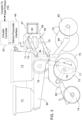
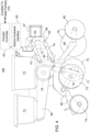
- FIG. 2 is a perspective view of an off-road vehicle 82 (e.g., tractor) that is towing a planting implement 83 of multiple row units 66 with adjustable down-force in accordance with a data map (301, 321) of down-force zones (e.g., cells or adjoining hexagonal cells that comprise a field).
- Row units 66 are associated with the implement 83 that is coupled to the off-road vehicle 82.
- electronic data processor 18 or implement control module 60 of the data processing system 14 may selectively activate seeding or planting of one or more row units 66, independently from other row units (e.g., as the implement traverses a path plan or path segment of a path plan).
- the implement 83 or planter comprises a first row unit 66 through an Nth row unit, where N equals any positive integer greater than two
- one or more of the row units 66, among the first row unit to the Nth row unit, inclusive may be activated for a corresponding geographic zone, cell or row segment, path segment or portion of the field, and/or during a certain activation time interval, which may be proportional to the velocity and speed of the implement 83 or planter, or a particular row unit 66. (e.g., stop, pause or suspend seeding or planting for time period).
- FIG. 3 is a side view of one embodiment of a row unit 66, with adjustable down-force and adjustable seeding rate to pause, disable, stop, or interrupt seeding for a no-planting time period within an exclusion zone 104 or at one or more successive exclusion points 110, of the planting implement of FIG. 3 .
- Each row unit 66 is mounted on a traverse member 67 of an implement 83 by a bracket 68 that is spaced apart from a horizontal frame member 69.
- One or more arms 70 are pivotably connected to the bracket 68 and to the horizontal frame member 69 at pivot points 84 to allow the vertical height of the horizontal frame member 69 to vary (e.g., with respect to the ground) from the vertical height of the transverse member 67; hence, to allow for some adjustment in the down-force applied to any of the following: the closer 74, the planting disk 75, and the opener 79.
- a pneumatic cylinder 71 is secured to the bracket 68 at one end (or an upper bracket portion) and secured (e.g., pivotably attached) to one of the arms 70 on the opposite end to adjust the down-force applied to any of the following: the closer 74, the planting disk 75, and the opener 79; or alternately, or cumulatively, to allow for the adjustment of the depth of the planted seed or the seed tube 76.
- a block diagram is associated with the pneumatic cylinder 71, where the block diagram comprises an actuator controller 63 that is coupled to an electro-pneumatic interface 64.
- the actuator controller 63 can be coupled to the data ports 16 of the data processing system 14 of FIG. 1A or FIG. 1B , for example.
- the electro-pneumatic interface 64 may be associated with pneumatic system or pump to control the pressure or flow of air or nitrogen in the pneumatic cylinder 71 to control the planting depth or down-force of the row unit 66, or in tandem with one or more other row units 66 of the implement 83.
- a seed container 73 or seed hopper is supported by or above the horizontal frame member 69.
- the seed container 73 feeds seeds into a seed metering device 78 that is generally below the seed container 73.
- the seed metering device 78 meters or controls the spacing of the seeds (planted in a row, furrow, depression or trench in the soil) based on or proportional to the ground speed of the implement 83 (e.g., planter).
- an opener 79 or opening wheel 80 that opens a furrow or trench in the soil.
- planting disk 75 that is associated with an end of a seed tube 76 or seed exit 77 in which seeds are dispensed into the opened furrow or trench in the soil.
- a closer 74 closes the trench or furrow or covers the planted seed with soil.
- the support 85 supports the opener 80, planting disk 75, and the closer 74.
- FIG. 4 is a side view of another embodiment of a row unit 166, with adjustable down-force, of the planting implement of FIG. 2 .
- the row unit 166 of FIG. 4 is similar the row unit 66 of FIG. 3 , except the row unit 166 replaces the pneumatic cylinder 71 with a hydraulic cylinder 72, or an electric actuator (e.g., linear motor or rotary electric motor with a screw assembly).
- an electric actuator e.g., linear motor or rotary electric motor with a screw assembly.
- the hydraulic cylinder 72 is secured to the bracket 68 at one end (or to an upper bracket portion) and secured to one of the arms 70 on the opposite end to allow for some adjustment in the down-force applied to any of the following: the closer 74, the planting disk 75, and the opener 79; alternately or cumulatively, the allow for adjustment of the depth of the planted seed or the seed exit 77 of the seed tube 76.
- a block diagram is associated with the hydraulic cylinder 72, where the block diagram comprises an actuator controller 63 that is coupled to an electro-hydraulic interface 65.
- the actuator controller 63 can be coupled to the data ports 16 of the data processing system 14 of FIG. 1A or FIG. 1B , for example.
- the electro-hydraulic interface 65 may be associated with hydraulic system or pump to control the pressure or flow of hydraulic fluid in the hydraulic cylinder 72 to control the planting depth or down-force of the row unit 66, or in tandem with one or more other row units 66 of the implement 83.
- the electrohydraulic interface 65 is optional and is not required if the hydraulic cylinder 72 is replaced with an electric actuator.
- the exclusion zone 104 comprises a travel segment configured to the width of the vehicle 82 or the implement 83.
- the travel segment may comprise a path segment or set of path segments that are joined together end to end to form a continuous or circuitous path for the vehicle 82 or implement 83, where each path segment may be substantially straight, curved (e.g., Bezier curve), arced, or otherwise configured in into a path or set of path segments that the vehicle or implement is capable of tracking, given width, dimensions, turning radius and other components.
- FIG. 5 illustrates a possible path plan 126 of a gap 83 in planted seeds or seedlings in a headland region 121 where, in a basic or simple configuration, all row units 66 of an implement 83 simultaneously stop, pause or suspend planting of seeds for a time period.
- central path segments 122 e.g., generally linear path segments
- headland path segments 123 e.g., an outer lap, outer pass, or segment that is generally linear in FIG. 5
- the vehicle 82 and/or implement 83 may track or traverse path segments, passes, rows or sequences of path segments, passes or rows.
- path segments and passes may be regarded as synonymous terms; similarly, path segments and rows may be regarded as synonymous terms.
- Rows may also refer to rows of seeds, seedlings or plants that have been planted or seeded during a prior path segment or previously by one or more row units 66 of the implement 83.
- the headland region 121 is a zone of the field that is bounded or defined by an inner boundary (e.g., inner substantially rectangular border with rounded corners) and an outer boundary (e.g., outer substantially rectangular border with rounded corners).
- the central region 125 of the field is the region within the inner boundary of the headland region 121.
- the vehicle 82 and/or the implement 83 traverses the dashed lines (122, 123) that are generally perpendicular to each other and also a curved path segment 124 of an end turn of FIG. 5 .
- the implement 83 e.g., planter automatically or responsive to operator (manual) commands
- the implement 83 (e.g., planter) makes a generally linear headland pass or traverses a substantially linear headland path segment 123 with gaps 128 illustrated in the headland path segments 123. No seeds or seedlings are planted within the gaps 128 or within one or more rows or row units 66 of the implement 83.
- the implement 83 After the implement 83 traverses in a direction of travel along the path segments 122, the implement 83 completes a curved path segment 124 or end turn (e.g., end of row turn) in the headland region 121. At least a portion of the end turn or curved path segment 124 of the implement 83 may be aligned with the gap 128 in the previous or upcoming headland path segments 123 to avoid or minimize potential damage to seeds, seedlings or plants in the headland region 121.
- end turn or curved path segment 124 of the implement 83 may be aligned with the gap 128 in the previous or upcoming headland path segments 123 to avoid or minimize potential damage to seeds, seedlings or plants in the headland region 121.
- the curved path segment 124 tends to extend outside the gap 128 before it can be aligned with (e.g., turned at approximately a right angle to align with) the headland path segment (123 or 127); hence, in the headland region 121 damage to previously planted seeds or seedlings may occur because of some inherent misalignment of the gap 128 with the vehicle and/or implement path, and its curved path segment 124.
- FIG. 6 illustrates a possible subsequent or later path plan 102 that an off-road vehicle and/or a towed implement may follow or track in a field or work area.
- the later path plan 102 or its later path segments are indicated with bold dashed lines in FIG. 6 .
- any path segment is a straight section, curved section, or contour section of a path plan of the vehicle, and/or a towed implement, where the section or segment is bounded by two points on the path plan and where the two points on the path plan may be defined with reference to, or translated to, real world coordinates of the vehicle, and/or its implement along a center-line of the vehicle and/or implement in the direction of travel.
- a previous or prior path plan 108 or its prior path segments are indicated by parallel contour segments.
- a complete path plan may comprise the prior path segments of a prior path plan 108 and the later path segments of a later path plan 102, or a sequence of the prior path segments of a prior path plan 108 and the later path segments of a later path plan 102.
- one or more prior path segments and later path segments of the complete path plan (102, 108) overlap with each other during turning or a curved path segment 109 of an off-road vehicle and/or towed planting implement in accordance with the disclosure.
- the prior headland path segment (of prior path plan 108) of the implement can interfere with or overlap with a present or later curved path segment 109 or end-turn segment of the implement (e.g., after the implement exits a central portion 105 of the field and enters the headland region 103).
- the interference or overlap defines exclusion points 110, which can be bounded by exclusion zones 104 or aggregated to define exclusion zones (e.g., to account for any uncertainty in the estimated position, heading, velocity, acceleration and/or attitude (pitch, roll or yaw angle) of the vehicle or implement).
- exclusion points 110 are indicated by X's on or that intercept the present or later path plan 102.
- the exclusion zones 104 are indicated as rectangles, although they could be defined as substantially hexagonal, circular, polygonal, elliptical or with other suitable geometric shapes.
- the prior pass or prior segment of prior path plan 108 (e.g., in the headland region 103) is somewhat parallel to the later pass or later segment of the present or later path plan 102 for one or more row units of the implement, but does not have proper full row alignment between the prior path segment and the later path segment of the implement.
- the closer spacing makes the seeds or seedlings in the plant rows susceptible to damage from tires, wheels or tracks of the vehicle 82 and/or implement 83, unless an exclusion zone 104 is used to compensate for the closer spacing. Accordingly, with an exclusion zone 104 or for a series of successive exclusion points 104 along a later path segment, one or row units 66 of the implement that are not adequately aligned to full proper target row spacings or prior seed or seedling rows from prior path segments, can be temporarily disabled or shut down, until adequate alignment of each row unit 66, on an individual and independent basis from other row units 66 (e.g., whose row unit paths establish plant rows when seeding is active), is later realized .
- the exclusion zone module 59 or electronic data processor 18 may identify "don't-plant” zones along previously planned paths or path segments of a sequence of path segments, where the seeds or seedlings would otherwise overlap or intersect with the tires, wheels or tracks of the implement 83 and/or vehicle 82.
- This information includes one or more of the following: (1) path segments, rows, or passes where the vehicle 83 (e.g., tractor) and implement 83 (e.g., planter) will travel through the field; and (2) path segments, rows, or passes where the vehicle 82 (e.g., tractor) and implement 83 (e.g., planter) will turn for end turns in the headlands (e.g., which defines where the turns will take place).
- the row units 66 of the implement 83 e.g., planter
- the implement 83 are capable of row-by-row unit 66, on/off planting control on a dynamic.
- the system and method of the disclosure are well-suite to support efficient planting operations to save seed and reduce crop damage that can be predicted ahead of time (e.g., in virtual or simulated the path planning process or preplanning process before the vehicle enters the field or on a dynamic basis once the vehicle and implement are engaged in a planting operation).
- the turn and headland vehicle passes can be managed determine possible interactions between tire/wheels/tracks and plants to automatically avoid planting rows, or portions of rows, along a series of exclusion points 110 or in exclusion zones 104, where damage or overlapping planting is likely to happen.
- the guidance module 26 and implement control module 60 operate collectively in accordance with a path plan provided by the path planning module 57 and exclusion zones provided by the exclusion zone module 59.
- the implement control module 60 is configured to support planter section control, planter row unit control or row units 66, variable planted seed (population) density or seedling (population) density by row or rows of the implement 83 (e.g., planter), and precision seed-planting equipment to accurately avoid planting exclusion points or exclusion zones where vehicle, the implement, or its or their tracks or tires are likely to cause seeds, seedling or plant damage.
- the path planning module 57 comprises an open field path planning system that determines the estimated passes that the vehicle 82 (e.g., tractor) and implement 83 (e.g., planter) will take to cover or traverse the entire field (in field passes as well as boundary or headland passes). Further, the path planning module 57 may determine parallel passes (e.g., to plant generally parallel rows of plants or crop in the field with defined row separation or spacing) and end turns near a boundary, edge or headland.
- the vehicle 82 e.g., tractor
- implement 83 e.g., planter
- the path interference estimator 58 or data processor estimates interference zones or overlapping passes of the vehicle and/or implement based on any of the following: (a) the planned path (e.g., coverage area that comprises parallel pass segments and end turn segments), (b) application of the planned path to specific equipment parameters, such as the parameters of vehicle 82 and implement 83 (e.g., planter), like planter width, row spacing of row units, turning radius of implement, turning radius of vehicle 82, hitch parameters of any hitch interconnecting the vehicle 82 and implement 83, and the like.
- the exclusion zone module 59 estimates exclusion points or exclusion zones based on predicted interference or overlap of vehicle and/or implement passes.
- the exclusion zone module 59 or data processor 18 marks no-plant zones, such as keep-out areas, coverage area boundaries, boundaries, flags or other techniques, to alert the vehicle and/or implement (e.g., planter) where it should turn planting of seeds or seedlings on/off to avoid later damage to seeds, seedlings or plants resulting therefrom.
- no-plant zones such as keep-out areas, coverage area boundaries, boundaries, flags or other techniques, to alert the vehicle and/or implement (e.g., planter) where it should turn planting of seeds or seedlings on/off to avoid later damage to seeds, seedlings or plants resulting therefrom.
- projections to tire paths or tracks of the vehicle and/or implement could be made from the raw path plans to understand each of the ground contact points near or in the exclusion zones.
- the exclusion zone module 59 is configured to map interaction points, exclusion points, or exclusion zones.
- the exclusion zones or exclusion points are uploaded to the guidance module 26 of the vehicle and/or implement and the implement control module 60 in addition to the navigation paths or planned paths of the path planning module 57 for the planting operation.
- the vehicle e.g., tractor
- towed implement e.g., planter
- FIG. 7 illustrates a possible path plan that comprises an earlier or prior path plan 208 of prior path plan segments and a subsequent or later path plan 102 of present or later path segments, where the later path segments can overlap with the prior path segments of the vehicle 82, and/or implement 83. Further, FIG. 7 illustrates exclusion points 110 along the present or later path segments and various exclusion zones 104 that can be defined about the exclusion points 110. As illustrated in the example of FIG. 7 , there is a core exclusion zone or central path exclusion zone 209 and the extended exclusion zone 204 (e.g., implement-width exclusion zone). As illustrated in FIG.
- the guidance module 26 defines a central guidance path 106, indicated by alternating long and short dashes, for the prior path plan 208 (e.g., that comprises contour path segments) and a central guidance path, indicated by bold dashes, for a present or later path plan 102 (e.g., that comprises a curved path segment, turn or end turn).
- FIG. 7 provides at least three discrete levels of exclusion zones for the planting row units to avoid damaging prior seeds or seedlings in rows and to avoid overplanting or double planting of interference regions.
- a first level e.g., minimum level
- the exclusion zone module 59, implement control module 60, or electronic data processor 18 is configured to deactivate (e.g., stop, pause or suspend seeding or planting for time period to suspend dispensing seeds into furrows of soil) the row unit or row units 66 at one or more exclusion points 110 (e.g., series of exclusion points) that intercept or cross the prior path segments of the prior path plan 208 in a sequence of path segments.
- exclusion points 110 e.g., series of exclusion points
- a second level e.g., intermediate level
- the exclusion zone module 59, implement control module 60, or electronic data processor 18 is configured to deactivate (e.g., stop, pause or suspend seeding or planting for time period) the row unit or row units 66 for central path exclusion zone 209 (e.g., series of exclusion points) that intercept or cross the portions of prior path segments of the prior path plan 208 in a sequence of path segments.
- the exclusion zone module 59, implement control module 60, or electronic data processor 18 is adapted to set or define one or more edges of the central path exclusion zone 209 by deactivating inner row units 66 on both sides of the implement 83 with respect to the central guidance path (e.g., or later path plan 102).
- a third level e.g., maximum level
- the exclusion zone module 59, implement control module 60, or electronic data processor 18 is configured to deactivate (e.g., stop, pause or suspend seeding or planting for time period) the row unit or row units 66 for extended exclusion zone 204 (e.g., series of exclusion points) that intercept or cross the portions of prior path segments of the prior path plan 208 in a sequence of path segments.
- the exclusion zone module 59, implement control module 60, or electronic data processor 18 is adapted to set or define one or more edges of the central path exclusion zone 209 (e.g., even up to the implement width 112 or swath width of the implement 83) by deactivating one or more row units 66 on both sides of the implement 83.
- FIG. 8 illustrates another possible later path plan 302 of later path segments of the vehicle 82 and/or implement 83 that can overlap or interfere with a earlier or prior path plan 306.
- the later path plan 302 indicated by bold dashed lines
- the prior path plan 306 indicated by bold solid lines
- the sets of parallel rows may define plant rows of seeds or seedlings, which are established by any number of active row units of the implement 83 via substantially linear path segments, curved path segments (e.g., as curved as contour lines), or both.
- the temporal exclusion zone 304 may be defined for a prior path plan or one or more prior path segments by a polygonal, trapezoidal, or other region where the later path segments or prior path segments overlap, whereas the temporal exclusion zone 304 expires for the present or later path plan to allow one set of (unidirectional) plant parallel plant rows 408 (e.g., vertical contour rows) to be planted.
- unidirectional plant parallel plant rows 408 e.g., vertical contour rows
- FIG. 8 may address potential intersection of seed, seedling or plant rows inside or outside of the headland region.
- the later path plan 302 (e.g., later pass) of the sequence of path segment is suspended, paused or discontinuously planted by row units 66 with zero seed or seedling population rate (or with a minimal seed or seedling population rate) for one or more rows in the temporal exclusion zone(s) 304 to maintain an average plant population per field area, and to avoid damage by the vehicle and/or implement during the later path plan 302 (e.g., later pass) of the sequence of the path plan.
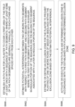
- FIG. 9 is a flow chart of one embodiment of a method for precise planting based on planned paths. The method of FIG. 9 begins in step S900.
- the path planning module 57 or electronic data processor 18 is configured to establish a path plan for a planter to cover a first area of the field at least once with a sequence of path segments, where at least some of the path segments are generally parallel to each other and spaced apart from each other.
- Any path segment may comprise one or more of the following: a generally straight path segment, a curved path segment, an arced path segment, a straight section, curved section, an arced section, or contour section of a path plan of the vehicle 82, and/or a towed implement 83, where the section or segment is bounded by two points on the path plan and where the two points on the path plan may be defined with reference to, or translated to, real world coordinates of the vehicle, and/or its implement along a center-line of the vehicle and/or implement in the direction of travel.
- a previous or prior path plan e.g., 108) or its prior path segments are indicated by parallel contour segments.
- a complete path plan may comprise the prior path segments of a prior path plan (e.g., 108, 208, 308) and the later path segments of a later path plan 102, or a sequence of the prior path segments of a prior path plan (e.g., 108, 208, 308) and the later path segments of a later path plan (e.g., 102).
- the path interference estimator 58 or electronic data processor 18 is configured to estimate potential interference between two or more path segments with respect to a first path segment and a second path segment, the first path segment (e.g., prior path segment) associated with an earlier scheduled portion of the sequence and the second path segment (e.g., later path segment) associated with a later scheduled portion of the sequence.
- Step S902 is carried out in accordance with various techniques, which may be applied separately or cumulatively.
- the potential interference is indicative of intersection or overlap of at least one previously scheduled row of planted seeds or seedlings for the first path segment (e.g., prior path segment) with the second path segment of the vehicle that is configured to propel the planter through the field.
- the potential interference is indicative intersection or overlap of a set of previously scheduled rows of planted seeds or seedlings for the first path segment (e.g., prior path segment) with the second path segment (e.g., later path segment) of the vehicle that is configured to propel the planter through the field.
- the potential interference is indicative of an intersection or overlap of a set of scheduled row of planted seeds or seedlings for the first path segment (e.g., prior path segment) with the second path segment (e.g., present or later path segment) of the implement or planter that is configured to propel the planter through the field.
- the exclusion zone module 59 or electronic data processor 18 is configured to estimate or to define an exclusion zone for the planter to prohibit planting of one or more rows of seeds or seedlings within the exclusion zone based on the estimated potential interference.
- the user interface or display supports an operator's inputting, obtaining or accepting the established path plan and determined exclusion zone.
- Step S904 may be executed in accordance with various examples, which may be applied separately or cumulatively.
- the previously scheduled rows are generally parallel to each other and wherein the exclusion zone has a generally rectangular boundary.
- the previously scheduled rows define contour segments that are parallel to each other and wherein the exclusion zone has a generally curved boundary that tracks the defined contour segments or path segments.
- an exclusion zone is within a headland of a field and comprises a unplanted travel path that is used and reused to traverse the established path plan to minimize damage from wheels, tracks or tires of the vehicle and the implement to previously planted seeds or plants.
- the exclusion zone comprises an unplanted travel path that is used and reused to traverse the established path plan to minimize damage from wheels, tracks or tires of the vehicle and the implement to previously planted seeds or plants during a subsequent agricultural operation, such as spraying, fertilizing, irrigating or applying other crop inputs.
- the exclusion zone comprises a segment of subsequent path plan for the vehicle or implement to travel or align the implement to a target location and pose on the field or an uncovered, remaining or untreated region of the field.
- step S906 the guidance module 26, implement control module 60 and/or electronic data processor 18 is configured to activating or executing the path plan and determined exclusion zone in accordance with the established path plan and determined exclusion zone.
- a (complete) path plan can comprise a sequence of prior path segments (of a prior path plan) and later path segments (of a later path plan), for example.
- the method and system of the disclosure is well-suited for avoiding soil compaction or concentrating the soil compaction into an unplanted exclusion zone (e.g., travel segment configured to the width of the vehicle or the implement) for travel of the vehicle amidst and adj acent to adjoining crop.
- an unplanted exclusion zone e.g., travel segment configured to the width of the vehicle or the implement
- the method and system described in this document can potentially reduce damage to planted seed or seedlings in the field by directing the vehicle tires, wheels, or tracks through the unplanted exclusion zone. Further, the method and system can facilitate use of less seeds or seedlings planted throughout the field.
Landscapes
- Engineering & Computer Science (AREA)
- Life Sciences & Earth Sciences (AREA)
- Remote Sensing (AREA)
- Radar, Positioning & Navigation (AREA)
- Soil Sciences (AREA)
- Environmental Sciences (AREA)
- Mechanical Engineering (AREA)
- Physics & Mathematics (AREA)
- General Physics & Mathematics (AREA)
- Aviation & Aerospace Engineering (AREA)
- Automation & Control Theory (AREA)
- Computer Networks & Wireless Communication (AREA)
- Control Of Position, Course, Altitude, Or Attitude Of Moving Bodies (AREA)
- Transplanting Machines (AREA)
- Guiding Agricultural Machines (AREA)
Abstract
Description
- This disclosure relates to a method and system for precise planting based on planned paths.
- In some background art, a planter can control selectively the row units of an implement, such as a planter. Further, an automatic guidance system may be used to guide a vehicle, or its implement to track a path plan. However, previous planting paths of an implement during the same season may interfere with subsequent planting paths of the implement during the same season, which can reduce crop yields and waste crop inputs, like seeds. With some agricultural practices, a buffer zone or headlands region around the field could be left unplanted to reduce such interferences albeit with a potential yield penalty for the unplanted buffer zone. Thus, there is a need a method and system for precise planting based on planned paths (e.g., to efficiently use crop inputs for maximum potential yield).
- In accordance with one embodiment, a method and system facilitates precise planting based on planned paths. A path planning module or electronic data processor is configured to establish a path plan for an implement (e.g., planter) to cover a first area of the field at least once with a sequence of path segments in which some path segments are generally parallel to each other and spaced apart. A path interference estimator or the electronic data processor is configured to estimate potential interference between two or more path segments with respect to a first path segment and a second path segment, wherein the first path segment is associated with an earlier scheduled portion of the sequence and the second path segment is associated with a later scheduled portion of the sequence. An exclusion zone module or the electronic data processor is configured to determine an exclusion zone for the implement (e.g., row units of a planter) to prohibit planting of one or more rows of seeds or seedlings within the exclusion zone based on the estimated potential interference. Responsive to user input via the user interface, the electronic data processor is configured to activate or execute the path plan and determined exclusion zone in accordance with the established path plan and determined exclusion zone.
-
-
FIG. 1A is a block diagram of one embodiment of a system for precise planting based on planned paths. -
FIG. 1B is a block diagram of another embodiment of a system for precise planting based on planned paths. -
FIG. 2 is a perspective view of a off-road vehicle that is towing a planting implement of multiple row units in accordance with planned paths. -
FIG. 3 is a side view of one embodiment of a row unit of the planting implement ofFIG. 2 . -
FIG. 4 is a side view of another embodiment of a row unit of the planting implement ofFIG. 2 . -
FIG. 5 illustrates a typical path plan where there tends to be overlap of rows in a headland region. -
FIG. 6 illustrates a possible path plan where path segments overlap with each other during turning of an off-road vehicle and a towed planting implement in accordance with the disclosure. -
FIG. 7 illustrates a possible path plan and associated exclusion zone where path segments overlap with each other during turning of an off-road vehicle and a towed implement. -
FIG. 8 illustrates another possible path plan where path segments overlap with each other. -
FIG. 9 is a flow chart of one embodiment of a method for precise planting based on planned paths. -
FIG. 1A is one embodiment of a block diagram of asystem 11 for determining a path plan for an off-road vehicle (e.g., 82 inFIG. 4 ) to control an implement (e.g., 83 inFIG. 4 ). InFIG. 1A , alone or together withFIG. 1B , thesystem 11 is capable of detecting motion data and attitude data by one or more sensors, such as one or more location-determining receivers (10, 210), one or more accelerometers (54, 56),gyroscope 55, or an internal measurement unit (IMU) (53, 153) that use accelerometers or gyroscopes. In one example, thesystem 11 may send a path plan or data message to an operator or end user of thedetection system 11 via a wireless communications channel and via auser interface 22 that is incorporated into a vehicle, such as adisplay 25. In an alternate embodiment, theuser interface 22 anddisplay 25 may be located remotely from the vehicle via a wireless link to support remote control or tele-operation of the vehicle by the operator. - In one embodiment, the
system 11 comprises an electronicdata processing system 14 that is coupled to a location-determiningreceiver 10 directly, or via avehicle data bus 12. The optional connection viavehicle data bus 12 is shown in dashed lines because it is optional and the connection between the electronicdata processing system 14 and location-determiningreceiver 10 may be direct, as indicated bytransmission line 13, which can be used separately or cumulatively with the interconnection via thevehicle data bus 12. The location-determiningreceiver 10 may have anantenna 81 mounted on the vehicle, on the implement or both. - In an alternate embodiment, a first location-determining
receiver 10 and itsantenna 81 are on or in the vehicle (e.g., 82 inFIG. 2 ); a second location-determining receiver 210 (inFIG. 1B ) and its antenna are on or in the implement (e.g., 83 inFIG. 2 ), where both the first location-determiningreceiver 10 and the second-location determining receiver 210 may comprise satellite navigation receivers (with or without differential correction data) or other location-determining receivers. - In one embodiment, the electronic
data processing system 14 comprises anelectronic data processor 18, one ormore data ports 16, auser interface 22 and adata storage device 24 coupled to adata bus 20. Theelectronic data processor 18 may comprise a processor, a microcontroller, a digital signal processor, an application specific integrated circuit (ASIC), a programmable logic array, a programmable logic device, a logic circuit, an arithmetic logic unit, a Boolean logic device, or another data processing device. Thedata storage device 24 may comprise one or more of the following: electronic memory, nonvolatile electronic memory, an optical data storage device, a magnetic data storage device, or other device for storing digital or analog data. - In one embodiment, the
data storage device 24 may store, retrieve, read and write one or more of the following items: aguidance module 26, apath planning module 57, apath interference estimator 58, anexclusion zone module 59, and an implement control module 60 (e.g., row unit control module). A module means software, electronics, or both, where software can include software instructions, executable files, data structures, and libraries, among other things. - As used in this document, configured to, adapted to and arranged to may refer any of the following items: (1) software or program instructions that are stored in the
data storage device 24 or other data storage and executable by thedata processor 18 to perform certain functions, software, (2) software or embedded firmware that are stored in the location-determining receiver (10, 210) or its memory or data storage to perform certain functions, or (3) electronic, electrical circuits or modules that can perform substantially equivalent functions to the software, embedded firmware or program instructions. - Any
data port 16 may comprise a data transceiver, buffer memory, or both. Theuser interface 22 may comprise one or more of the following: a display 25 (e.g., display), a touch screen display, a keypad, a keyboard, a control panel, a pointing device (e.g., electronic mouse), or another device for entry or output of data from thedata processing system 14. - In one embodiment, a
wheel angle sensor 51, one or more accelerometers (54, 56), arotational speed sensor 52, an optional IMU (53, 153) and adata bus 20 are coupled to thedata ports 16. The electronicdata processing system 14 communicates todata ports 16 directly, or indirectly via thedata bus 20. Further, thedata ports 16 support the communication of data messages to, from or between, or among any of the following: theelectronic data processor 18, thedata storage device 24, any modules, data, files, libraries, or software within thedata storage device 24, the location-determining receiver (10, 210) thewheel angle sensor 51, one or more accelerometers (54, 56), arotational speed sensor 52, an optional IMU and adata bus 20. - In one embodiment, the optional IMU 53 is a separate device, whereas in other embodiments, the IMU 153 is integral with the location-determining
receiver 10. The optional separate IMU 53 comprises one ormore accelerometers 54 and agyroscope 55, where theaccelerometers 54 may be arranged on orthogonal axes with respect to each other to facilitate detection of vehicle attitude, such as roll angle, pitch angle and yaw angle of a vehicle. - In
FIG. 1A , thesteering controller 40, thepropulsion controller 44 and thebraking controller 48 are coupled to thevehicle data bus 12. For example, thedata processing system 14 can communicate with thesteering controller 40, thepropulsion controller 44 and thebraking controller 48, and vice versa. In one embodiment, thesteering controller 40 is coupled to thesteering system 42, such as an electrical motor or electrohydraulic device that is mechanically coupled to a steering mechanism (e.g., rack-and-pinion or Ackerman steering system) for controlling the angular orientation of one or more wheels about a generally vertical axis. In one embodiment, thepropulsion controller 44 may comprise an electronic engine controller for controlling a throttle or fuel metering system of apropulsion system 46, such as internal combustion engine. In another embodiment, apropulsion controller 44 may comprise an inverter or motor controller for controlling apropulsion system 46, such as a drive motor of a hybrid or electric vehicle. In one embodiment, thebraking controller 48 interfaces with abraking system 50, such as hydraulic braking system, an electrohydraulic braking system, a cable braking system, or an electromechanical braking system to stop or decelerate the vehicle. - In one configuration, the
guidance module 26 controls the vehicle to track or follow a path plan, a planned path, such as sequence of one or more interconnected path segments, where one or more path segments may comprise any of the following: generally straight path segments, curved path segments, arced path segments, or otherwise. Within a sequence of a path plan or planned path, aguidance module 26 orpath planning module 57 is configured to execute or process a previous or prior path segment before execution or processing of a present, subsequent or later path segment. Further, a path plan may comprise a generally linear path plan, a curved path plan, a contour path plan, a spiral path plan, a coverage area path plan, or other path plan, For example, a path plan may comprise any of the following: one or more linear path segments or rows, curved path segments or turns, such as an end turn, a key-hole end turn, a loop end turn, a row-skipping end turn. In the automated guidance mode, in certain vehicle configurations theguidance module 26 can control the steering, propulsion, and braking of the vehicle. For example, in the automated guidance mode, theguidance module 26 can communicate with one or more of the following controllers to direct and guide the vehicle:steering controller 40,propulsion controller 44 andbraking controller 48. - In
FIG. 1A in accordance with one embodiment, thesystem 11 comprises one or more location-determining receivers (10, 210) for estimating a position, motion, and attitude data of the vehicle (82 inFIG. 2 ), or its implement (e.g., 83 inFIG. 2 ), or both. As used in the disclosure, attitude refers to roll angle, pitch angle and yaw angle, or motion data associated with roll angle, pitch angle and yaw angle. As used in the disclosure, motion data comprises velocity data (e.g., speed data), acceleration data, or both. The velocity data and acceleration data may be expressed as vectors. As used in the disclosure, a yaw angle or heading can refer to: (1) an angular direction of travel of the vehicle with reference to due North or magnetic North, or (2) a yaw or yaw angle of the vehicle with reference to coordinate system, such as a Cartesian coordinate system. - In an alternate embodiment, a first location-determining
receiver 10 or itsantenna 81 is mounted on the vehicle for estimating a position, motion or attitude data of the vehicle (82 inFIG. 4 ) and a second location-determiningreceiver 210 is mounted on the implement (e.g., 83 inFIG. 2 ) for estimating a position, motion or attitude data of the implement that is coupled to the vehicle; position, motion and attitude data is available for the vehicle, its implement or both for processing by theelectronic data processor 18 to execute the software instructions associated with modules, estimators, or other components within thedata storage device 24. - In one embodiment, the location-determining receiver (10, 210) (e.g., satellite navigation receiver), alone or together with a wireless communications device, has a pair of
antennas 81 that are spaced apart with a known orientation. Further, the location-determining receiver (10, 210) or theelectronic data processor 18 can couple (e.g., selectively or switchably in rapid succession during the same epoch) eitherantenna 81 of the pair ofantennas 81 to support estimation of the attitude of the pair of antennas when the vehicle or implement is at a fixed position or substantially the same position. For example, the pair ofantennas 81 are spaced apart by a known distance on an axis with a known or fixed orientation (e.g., compound angular offset in one or more dimensions) to the longitudinal axis (in the direction of travel of the vehicle) and vertical axis of the vehicle. The location-determining receiver (10, 210) may estimate a first position (e.g., in three dimensions) of thefirst antenna 81 and a second position (e.g., in three dimensions) of thesecond antenna 81. Accordingly, the data processor or the location-determining receiver (10, 210) may estimate the precise attitude (e.g., yaw data, roll data, or both) of the vehicle, or its implement, based on the first position and the second position for the same epoch or measurement period, with or without augmentation by the correction data. - In one embodiment, a wireless communications device (47, 147) is coupled to a data port of a location-determining receiver (10, 210) or a
vehicle data bus 12 to augment the received satellite signals and associated carrier phase measurements of the received satellite signals (e.g., of at least four satellites) at the location-determining receiver (10, 210). For example, the wireless communications device (47, 147) may comprise a separate receiver or transceiver (e.g., satellite, cellular, or wireless device) may receive the correction data or differential correction data via a wireless signal transmitted from a satellite or a terrestrial base station (e.g., real-time kinematic (RTK) base station). The wireless communications device (47, 147) may receive correction data from one or more of the following sources of correction data: (a) differential correction data from local base stations or local reference receivers operating in a real-time-kinematic (RTK) mode, (b) correction data associated with a precise-point-position (PPP) satellite navigation system with precise orbital correction data for satellites and satellite clocks in a PPP mode, (c) correction data applicable to a satellite navigation system, and correction data (e.g., carrier-phase offset or position vector offset) provided from a hub or central processing center in communication a network of reference satellite navigation receivers, and (d) other correction data is commercially available from local, wide-area, regional, or global correction or satellite data augmentation services. - In one embodiment, the location-determining receiver (10, 210) provides one or more of the following types of data for a vehicle, and/or its implement: yaw data (e.g., heading data), roll data, pitch data, position data, velocity data, and acceleration data (e.g., as vectors or in two or three dimensional coordinates). The location-determining receiver (10, 210) may comprise a satellite navigation receiver, a Global Navigation Satellite System (GNSS) receiver, a Global Positioning System (GPS) receiver, or another receiver for determining position data, motion data or attitude data. In one embodiment, a location-determining receiver (10, 210) provides location data, path heading data, vehicle heading data, velocity data, and acceleration data along target path or path plan to the
data processing system 14 orguidance module 26. - In one embodiment, an optional separate inertial measurement unit 53 (IMU) may be separate from the location-determining
receiver 10 or an optionalintegral IMU 153 may be integrated with thelocation determining receiver 10. The optional nature of theseparate IMU 53 and theintegral IMU 153 is indicated by dashed lines inFIG. 1A . Theseparate IMU 53 or theintegral IMU 153 can estimate the attitude, yaw angle, yaw rate, roll, roll rate, pitch angle, pitch rate for the vehicle, or its implement, for instance. The yaw rate may refer to yaw angular velocity, yaw angular acceleration or both; the roll rate may refer to roll angular velocity, roll angular acceleration or both; the pitch rate may refer to pitch angular velocity, pitch angular acceleration or both. - In one configuration, the
data processing system 14 comprises a roll sensor, pitch sensor and a yaw sensor. Any roll sensor, pitch sensor and yaw sensor may comprise an accelerometer (e.g., 54, 56), a three-axis accelerometer, a gyroscope, an IMU, or another sensor. In general, each sensor, such as roll sensor, which is based on accelerometer measurements and/or gyroscope measurements, is subject to bias in their measurements that may arise over time, unless the sensor is calibrated or recalibrated (e.g., by the carrier phase measurements of the location-determining receiver (10, 210).) - In one embodiment, the roll sensor comprises a
first accelerometer 56 that is configured to measure roll angle, roll angular velocity, and/or roll angular acceleration of the vehicle. Similarly, the pitch sensor comprises asecond accelerometer 156 that is configured to measure pitch angle, pitch angular velocity and/or pitch angular acceleration of the vehicle. In one configuration, the roll sensor and the pitch sensor may provide attitude data and motion data, such as roll data and pitch data, that theelectronic data processor 18 can use to determine a surface roughness estimate. - In another embodiment, the accelerometers (56, 156),
gyroscopes 55 or IMU (53, 153) of thedata processing system 14 detect or measure one or more of the following: pitch angle, pitch motion data, roll angle and roll motion data. - In one embodiment, a motion sensor is configured to detect motion data of an off-road vehicle traversing a field or work site during a sampling interval. The motion data comprises ground speed or velocity of the off-road vehicle, or its implement. A first sensor (e.g.,
accelerometer 56 or IMU (53, 153)) is configured to: (a) detect pitch data of the off-road vehicle, or its implement, for the sampling interval to obtain a pitch acceleration, or (b) detect pitch angular acceleration data for the sampling interval. A second sensor (e.g.,accelerometer 156 or IMU (53, 153)) is configured to: (a) detect roll data of the off-road vehicle, or its implement, for the sampling interval to obtain a roll acceleration, or (b) detect roll angular acceleration data of the off-road vehicle, or its implement, for the sampling interval. If the first sensor only detects pitch angle with respect to time, theelectronic data processor 18 is configured to derive the pitch angle acceleration from a derivative of the detected pitch angle with respect to time. Similarly, if the second sensor only detects roll angle with respect to time, anelectronic data processor 18 is configured to derive the roll angle acceleration from a derivative of the detected roll angle with respect to time. - In one embodiment, a
rotational speed sensor 52 is configured to measure a drivetrain-derived wheel speed. - In
FIG. 1A , theelectronic data processor 18 or apath planning module 57 is configured to determine a path plan, such as prior path plan comprising one or more prior path segments and later path plan comprising one or more later path segments. Theexclusion zone module 59 may be configured to estimate exclusion points or exclusion zones (e.g., cells) with reference to the path plan, planned paths or any constituent prior path segments, later path segments or both, as a vehicle (e.g., 82 inFIG. 2 ) prepares to traverse or traverses the field or work site over multiple sampling intervals. - An
electronic data processor 18 orpath planning module 57 is configured to generate agraphical display 25 that illustrates one or more estimated zones (e.g.,exclusions zones 104 or exclusion points 110) of corresponding path plan within the field or work site. Further, anend user interface 22 is adapted to display 25 thegraphical display 25 to a user or operator of the vehicle. In some configurations, the graphical display that illustrates proposed, candidate or existing path plans and exclusion zones (e.g., 104) for thevehicle 82 and/or implement 83, although graphical representations fall within the scope of the disclosure and appended claims. - A location-determining receiver (10, 210) can determine a position of a vehicle (82), or its implement (83), in the field or in the work site with respect to the estimated zones, such as headland regions of a field, a central region of a field, exclusion zones and exclusion points along a path plan or path segment.
- In one embodiment, the
exclusion zone module 59 can be operated in accordance with various techniques, which may be applied separately or cumulatively. Under a first technique, anexclusion zone module 59 is configured to estimate exclusion-zone settings (e.g., target exclusion-zone settings) for the implement 83 consistent with alignment and/or overlap of the determined position (e.g., in two or three dimensional coordinates) of the implement 83 (or vehicle 82) and the estimatedexclusion zones 104 or exclusion points 110. Under a second technique, anexclusion zone module 59 configured to estimate exclusion-zone settings (e.g., target exclusion-zone settings) associated with thecorresponding row units 66 of the implement 83 consistent with alignment and/or overlap of the determined position of the implement 83 and the estimatedexclusion zones 104 or exclusion points 110, wheredifferent row units 66 can have different exclusion-zone settings if thedifferent row units 66 of the implement fall within different estimated exclusion-zones of the corresponding exclusion zone ranges. - As illustrated in
FIG. 1A in conjunction withFIG. 3 orFIG. 4 , the implementcontrol module 60 oractuator controller 63 can be operated in accordance with various procedures that may be applied separately or cumulatively. Under a first procedure, an implementcontrol module 60, theactuator controller 63, or both are configured to control an actuator (71, 72) (e.g., via an interface (64, 65)) to adjust the estimated down-force setting for corresponding zones. Under a second procedure, an implementcontrol module 60,actuator controller 63, or both are configured to control an actuator (71, 72) (e.g., via aninterface 64, 65) to increase or increment the down-force setting for a primary corresponding zones of a field, or to decrease or decrement the down-force setting for a secondary corresponding zones of a field to transition between different down-force settings. - The
system 111 ofFIG. 1B is similar to thesystem 11 ofFIG. 1A , except thesystem 111 further comprises animaging system 61, a secondlocation determining receiver 210, awireless communications device 147. As illustrated theimaging system 61 is coupled to one ormore data ports 16 of thedata processing system 14. Like reference numbers inFIG. 1A andFIG. 1B indicate like features or elements. - In one embodiment, the
imaging system 61 is configured to collect image data of the field or work site in a forward field of view of the vehicle in one or more electromagnetic frequency bands or wavelengths, such as humanly visible light, infra-red radiation, ultra-violet radiation, or the like. For example, theimaging system 61 may comprise a stereo imaging system or stereo camera for collecting stereoscopic images or three-dimensional image clouds or three-dimensional image constellations of ground regions within the field of view (e.g., forward facing region or zone in front of the vehicle 82). In some configurations, theimaging system 61 orelectronic data processor 18 can align (e.g., or stitch together) successive local images to assemble an aggregate view of an entire field or work area that is traversed or surveyed by the off-road vehicle equipped with theimaging system 61. For example, theimaging system 61 orelectronic data processor 18 may assign or identify two or three dimensional reference points in successive local images to spatially align successive images to assemble an aggregate view of an entire field or work area. - The second location-determining
receiver 210 is the same or similar to the location-determiningreceiver 10, which may be referred to as the first location determining receiver. However, the first location-determiningreceiver 10 may be mounted on or in thevehicle 82, or its implement 83. If both a first location-determiningreceiver 10 and second location-determiningreceiver 210 are present, the second location-determiningreceiver 210 is typically mounted on or in the implement 83 and the first location-determiningreceiver 10 is mounted on or in thevehicle 82. Thewireless communications device 147 is the same or similar to thewireless communications device 47. For example, thewireless communications device 147 is coupled to the second location-determiningreceiver 210 to provide correction data to it. - In accordance with one embodiment, a method and system facilitates precise planting based on planned paths, consistent with
exclusion points 110 orexclusion zones 104 along paths where seeds are not planted for one ormore row units 66 to reduce potential damage to previously planted seeds or seedlings near or within the exclusion points 110 orexclusion zones 104. The system comprises anelectronic data processor 18 is coupled todata storage device 24 for storing one or more modules or software instructions that are executable by thedata processor 18. In one embodiment, the system comprises apath planning module 57 orelectronic data processor 18 configured to establish a path plan for a planter to cover a first area of the field at least once with a sequence of path segments in which some of the path segments are generally parallel to each other and spaced apart. Apath interference estimator 58 or theelectronic data processor 18 is configured to estimate potential interference between two or more path segments with respect to a first path segment (e.g., earlier or prior path segment) and a second path segment (e.g., present or later path segment), wherein the first path segment is associated with an earlier scheduled portion of the sequence and the second path segment is associated with a later scheduled portion of a sequence of path segments within a planned path or path plan. Anexclusion zone module 59 or theelectronic data processor 18 is configured to determine anexclusion zone 104 for one ormore row units 66 of the implement (e.g., planter) to prohibit planting of one or more rows of seeds or seedlings within theexclusion zone 104 based on the estimated potential interference. Responsive to user input via theuser interface 22, theelectronic data processor 18 is configured to activate or execute the path plan anddetermined exclusion zone 104 in accordance with the established path plan anddetermined exclusion zone 104. -
FIG. 2 is a perspective view of an off-road vehicle 82 (e.g., tractor) that is towing a planting implement 83 ofmultiple row units 66 with adjustable down-force in accordance with a data map (301, 321) of down-force zones (e.g., cells or adjoining hexagonal cells that comprise a field).Row units 66 are associated with the implement 83 that is coupled to the off-road vehicle 82. Moreover,electronic data processor 18 or implementcontrol module 60 of thedata processing system 14 may selectively activate seeding or planting of one ormore row units 66, independently from other row units (e.g., as the implement traverses a path plan or path segment of a path plan). For example, if the implement 83 or planter comprises afirst row unit 66 through an Nth row unit, where N equals any positive integer greater than two, one or more of therow units 66, among the first row unit to the Nth row unit, inclusive, may be activated for a corresponding geographic zone, cell or row segment, path segment or portion of the field, and/or during a certain activation time interval, which may be proportional to the velocity and speed of the implement 83 or planter, or aparticular row unit 66. (e.g., stop, pause or suspend seeding or planting for time period). -
FIG. 3 is a side view of one embodiment of arow unit 66, with adjustable down-force and adjustable seeding rate to pause, disable, stop, or interrupt seeding for a no-planting time period within anexclusion zone 104 or at one or more successive exclusion points 110, of the planting implement ofFIG. 3 . - Each
row unit 66 is mounted on atraverse member 67 of an implement 83 by abracket 68 that is spaced apart from ahorizontal frame member 69. One ormore arms 70 are pivotably connected to thebracket 68 and to thehorizontal frame member 69 at pivot points 84 to allow the vertical height of thehorizontal frame member 69 to vary (e.g., with respect to the ground) from the vertical height of thetransverse member 67; hence, to allow for some adjustment in the down-force applied to any of the following: the closer 74, theplanting disk 75, and theopener 79. - As illustrated in
FIG. 3 apneumatic cylinder 71 is secured to thebracket 68 at one end (or an upper bracket portion) and secured (e.g., pivotably attached) to one of thearms 70 on the opposite end to adjust the down-force applied to any of the following: the closer 74, theplanting disk 75, and theopener 79; or alternately, or cumulatively, to allow for the adjustment of the depth of the planted seed or theseed tube 76. - In
FIG. 3 , a block diagram is associated with thepneumatic cylinder 71, where the block diagram comprises anactuator controller 63 that is coupled to an electro-pneumatic interface 64. Theactuator controller 63 can be coupled to thedata ports 16 of thedata processing system 14 ofFIG. 1A orFIG. 1B , for example. Meanwhile, the electro-pneumatic interface 64 may be associated with pneumatic system or pump to control the pressure or flow of air or nitrogen in thepneumatic cylinder 71 to control the planting depth or down-force of therow unit 66, or in tandem with one or moreother row units 66 of the implement 83. - In one embodiment, a
seed container 73 or seed hopper is supported by or above thehorizontal frame member 69. Theseed container 73 feeds seeds into aseed metering device 78 that is generally below theseed container 73. In some configurations, theseed metering device 78 meters or controls the spacing of the seeds (planted in a row, furrow, depression or trench in the soil) based on or proportional to the ground speed of the implement 83 (e.g., planter). - In the front of the planter, there is an
opener 79 oropening wheel 80 that opens a furrow or trench in the soil. Behind theopener 79, there is plantingdisk 75 that is associated with an end of aseed tube 76 orseed exit 77 in which seeds are dispensed into the opened furrow or trench in the soil. Behind theplanting disk 75 and theseed exit 77, a closer 74 closes the trench or furrow or covers the planted seed with soil. As illustrated, thesupport 85 supports theopener 80,planting disk 75, and the closer 74. -
FIG. 4 is a side view of another embodiment of arow unit 166, with adjustable down-force, of the planting implement ofFIG. 2 . Like reference numbers in any two drawings, such asFIG. 1A ,FIG. 1B ,FIG. 2 ,FIG. 3 andFIG. 4 indicate like elements. For example, therow unit 166 ofFIG. 4 is similar therow unit 66 ofFIG. 3 , except therow unit 166 replaces thepneumatic cylinder 71 with ahydraulic cylinder 72, or an electric actuator (e.g., linear motor or rotary electric motor with a screw assembly). - As illustrated in
FIG. 4 , thehydraulic cylinder 72 is secured to thebracket 68 at one end (or to an upper bracket portion) and secured to one of thearms 70 on the opposite end to allow for some adjustment in the down-force applied to any of the following: the closer 74, theplanting disk 75, and theopener 79; alternately or cumulatively, the allow for adjustment of the depth of the planted seed or theseed exit 77 of theseed tube 76. - In
FIG. 4 , a block diagram is associated with thehydraulic cylinder 72, where the block diagram comprises anactuator controller 63 that is coupled to an electro-hydraulic interface 65. Theactuator controller 63 can be coupled to thedata ports 16 of thedata processing system 14 ofFIG. 1A orFIG. 1B , for example. Meanwhile, the electro-hydraulic interface 65 may be associated with hydraulic system or pump to control the pressure or flow of hydraulic fluid in thehydraulic cylinder 72 to control the planting depth or down-force of therow unit 66, or in tandem with one or moreother row units 66 of the implement 83. In an alternate embodiment, theelectrohydraulic interface 65 is optional and is not required if thehydraulic cylinder 72 is replaced with an electric actuator. - Under one technique, the
exclusion zone 104 comprises a travel segment configured to the width of thevehicle 82 or the implement 83. The travel segment may comprise a path segment or set of path segments that are joined together end to end to form a continuous or circuitous path for thevehicle 82 or implement 83, where each path segment may be substantially straight, curved (e.g., Bezier curve), arced, or otherwise configured in into a path or set of path segments that the vehicle or implement is capable of tracking, given width, dimensions, turning radius and other components. -
FIG. 5 illustrates a possible path plan 126 of agap 83 in planted seeds or seedlings in aheadland region 121 where, in a basic or simple configuration, allrow units 66 of an implement 83 simultaneously stop, pause or suspend planting of seeds for a time period. InFIG. 5 , there tends to be overlap of central path segments 122 (e.g., generally linear path segments) that exit acentral region 125 of the field with headland path segments 123 (e.g., an outer lap, outer pass, or segment that is generally linear inFIG. 5 ) within aheadland region 121 or headland zone. As used throughout this document, thevehicle 82 and/or implement 83 may track or traverse path segments, passes, rows or sequences of path segments, passes or rows. For example, path segments and passes may be regarded as synonymous terms; similarly, path segments and rows may be regarded as synonymous terms. Rows may also refer to rows of seeds, seedlings or plants that have been planted or seeded during a prior path segment or previously by one ormore row units 66 of the implement 83. As illustrated inFIG. 5 , theheadland region 121 is a zone of the field that is bounded or defined by an inner boundary (e.g., inner substantially rectangular border with rounded corners) and an outer boundary (e.g., outer substantially rectangular border with rounded corners). Thecentral region 125 of the field is the region within the inner boundary of theheadland region 121. - In one illustrative example the
vehicle 82 and/or the implement 83 traverses the dashed lines (122, 123) that are generally perpendicular to each other and also acurved path segment 124 of an end turn ofFIG. 5 . In theheadland region 121, to the extent that the implement 83 crosses or traverses in the direction of travel along generally linearheadland path segments 123, for a planting-suspension time period the implement 83 (e.g., planter automatically or responsive to operator (manual) commands) may stop planting seeds or seedlings for allrow units 66 of an implement 83 in a simple configuration during a common time period (e.g. or for one ormore row units 66 in a complex configuration for various discrete time periods). Here, inFIG. 5 , the implement 83 (e.g., planter) makes a generally linear headland pass or traverses a substantially linearheadland path segment 123 withgaps 128 illustrated in theheadland path segments 123. No seeds or seedlings are planted within thegaps 128 or within one or more rows orrow units 66 of the implement 83. - After the implement 83 traverses in a direction of travel along the
path segments 122, the implement 83 completes acurved path segment 124 or end turn (e.g., end of row turn) in theheadland region 121. At least a portion of the end turn orcurved path segment 124 of the implement 83 may be aligned with thegap 128 in the previous or upcomingheadland path segments 123 to avoid or minimize potential damage to seeds, seedlings or plants in theheadland region 121. However, thecurved path segment 124 tends to extend outside thegap 128 before it can be aligned with (e.g., turned at approximately a right angle to align with) the headland path segment (123 or 127); hence, in theheadland region 121 damage to previously planted seeds or seedlings may occur because of some inherent misalignment of thegap 128 with the vehicle and/or implement path, and itscurved path segment 124. -
FIG. 6 illustrates a possible subsequent or later path plan 102 that an off-road vehicle and/or a towed implement may follow or track in a field or work area. The later path plan 102 or its later path segments are indicated with bold dashed lines inFIG. 6 . As used throughout this document, any path segment is a straight section, curved section, or contour section of a path plan of the vehicle, and/or a towed implement, where the section or segment is bounded by two points on the path plan and where the two points on the path plan may be defined with reference to, or translated to, real world coordinates of the vehicle, and/or its implement along a center-line of the vehicle and/or implement in the direction of travel. Meanwhile, a previous or prior path plan 108 or its prior path segments are indicated by parallel contour segments. A complete path plan may comprise the prior path segments of aprior path plan 108 and the later path segments of alater path plan 102, or a sequence of the prior path segments of aprior path plan 108 and the later path segments of alater path plan 102. - In
FIG. 6 , one or more prior path segments and later path segments of the complete path plan (102, 108) overlap with each other during turning or acurved path segment 109 of an off-road vehicle and/or towed planting implement in accordance with the disclosure. For example, the prior headland path segment (of prior path plan 108) of the implement can interfere with or overlap with a present or later curvedpath segment 109 or end-turn segment of the implement (e.g., after the implement exits acentral portion 105 of the field and enters the headland region 103). - In one example, as the curvature of
curved path segment 109 of an end turn (e.g., later or subsequent pass or segment of a sequence of the path plan) exceeds the curvature of the prior path segments of prior path plan 108 (e.g., prior headland pass or prior segment of a sequence of the path plan) the interference or overlap defines exclusion points 110, which can be bounded byexclusion zones 104 or aggregated to define exclusion zones (e.g., to account for any uncertainty in the estimated position, heading, velocity, acceleration and/or attitude (pitch, roll or yaw angle) of the vehicle or implement). Here, inFIG. 6 , the exclusion points 110 are indicated by X's on or that intercept the present orlater path plan 102. Similarly, theexclusion zones 104 are indicated as rectangles, although they could be defined as substantially hexagonal, circular, polygonal, elliptical or with other suitable geometric shapes. - In another example, the prior pass or prior segment of prior path plan 108 (e.g., in the headland region 103) is somewhat parallel to the later pass or later segment of the present or later path plan 102 for one or more row units of the implement, but does not have proper full row alignment between the prior path segment and the later path segment of the implement. For instance, there may be an intermediate or fractional row alignment between the prior path segment and the later path segment of the implement and its row units, which is consistent with closer spacing than a standard row separation or standard row spacing between potential seeds or seedlings of the prior path segment and later path segment for one or more row units. The closer spacing makes the seeds or seedlings in the plant rows susceptible to damage from tires, wheels or tracks of the
vehicle 82 and/or implement 83, unless anexclusion zone 104 is used to compensate for the closer spacing. Accordingly, with anexclusion zone 104 or for a series of successive exclusion points 104 along a later path segment, one orrow units 66 of the implement that are not adequately aligned to full proper target row spacings or prior seed or seedling rows from prior path segments, can be temporarily disabled or shut down, until adequate alignment of eachrow unit 66, on an individual and independent basis from other row units 66 (e.g., whose row unit paths establish plant rows when seeding is active), is later realized . For example, theexclusion zone module 59 orelectronic data processor 18 may identify "don't-plant" zones along previously planned paths or path segments of a sequence of path segments, where the seeds or seedlings would otherwise overlap or intersect with the tires, wheels or tracks of the implement 83 and/orvehicle 82. - With the advent of path planning for agricultural operations, more information about the future planter path segments or implement 83 passes is known up-front before planting begins. This information includes one or more of the following: (1) path segments, rows, or passes where the vehicle 83 (e.g., tractor) and implement 83 (e.g., planter) will travel through the field; and (2) path segments, rows, or passes where the vehicle 82 (e.g., tractor) and implement 83 (e.g., planter) will turn for end turns in the headlands (e.g., which defines where the turns will take place). In
FIG. 2 , therow units 66 of the implement 83 (e.g., planter) are capable of row-by-row unit 66, on/off planting control on a dynamic. The system and method of the disclosure are well-suite to support efficient planting operations to save seed and reduce crop damage that can be predicted ahead of time (e.g., in virtual or simulated the path planning process or preplanning process before the vehicle enters the field or on a dynamic basis once the vehicle and implement are engaged in a planting operation). The turn and headland vehicle passes can be managed determine possible interactions between tire/wheels/tracks and plants to automatically avoid planting rows, or portions of rows, along a series of exclusion points 110 or inexclusion zones 104, where damage or overlapping planting is likely to happen. - In one configuration, the
guidance module 26 and implementcontrol module 60 operate collectively in accordance with a path plan provided by thepath planning module 57 and exclusion zones provided by theexclusion zone module 59. Further, the implementcontrol module 60 is configured to support planter section control, planter row unit control orrow units 66, variable planted seed (population) density or seedling (population) density by row or rows of the implement 83 (e.g., planter), and precision seed-planting equipment to accurately avoid planting exclusion points or exclusion zones where vehicle, the implement, or its or their tracks or tires are likely to cause seeds, seedling or plant damage. - In some configurations, the
path planning module 57 comprises an open field path planning system that determines the estimated passes that the vehicle 82 (e.g., tractor) and implement 83 (e.g., planter) will take to cover or traverse the entire field (in field passes as well as boundary or headland passes). Further, thepath planning module 57 may determine parallel passes (e.g., to plant generally parallel rows of plants or crop in the field with defined row separation or spacing) and end turns near a boundary, edge or headland. Thepath interference estimator 58 or data processor estimates interference zones or overlapping passes of the vehicle and/or implement based on any of the following: (a) the planned path (e.g., coverage area that comprises parallel pass segments and end turn segments), (b) application of the planned path to specific equipment parameters, such as the parameters ofvehicle 82 and implement 83 (e.g., planter), like planter width, row spacing of row units, turning radius of implement, turning radius ofvehicle 82, hitch parameters of any hitch interconnecting thevehicle 82 and implement 83, and the like. Theexclusion zone module 59 estimates exclusion points or exclusion zones based on predicted interference or overlap of vehicle and/or implement passes. Theexclusion zone module 59 ordata processor 18 marks no-plant zones, such as keep-out areas, coverage area boundaries, boundaries, flags or other techniques, to alert the vehicle and/or implement (e.g., planter) where it should turn planting of seeds or seedlings on/off to avoid later damage to seeds, seedlings or plants resulting therefrom. Optionally, projections to tire paths or tracks of the vehicle and/or implement could be made from the raw path plans to understand each of the ground contact points near or in the exclusion zones. - In one configuration, the
exclusion zone module 59 is configured to map interaction points, exclusion points, or exclusion zones. The exclusion zones or exclusion points are uploaded to theguidance module 26 of the vehicle and/or implement and the implementcontrol module 60 in addition to the navigation paths or planned paths of thepath planning module 57 for the planting operation. During planting, the vehicle (e.g., tractor) and towed implement (e.g., planter) will follow the planned paths and areas of predicted interaction, such as exclusion points and exclusion zones, will not be planted with seeds or seedlings to avoid later damage to such seeds or seedlings that would otherwise likely occur. -
FIG. 7 illustrates a possible path plan that comprises an earlier or prior path plan 208 of prior path plan segments and a subsequent or later path plan 102 of present or later path segments, where the later path segments can overlap with the prior path segments of thevehicle 82, and/or implement 83. Further,FIG. 7 illustrates exclusion points 110 along the present or later path segments andvarious exclusion zones 104 that can be defined about the exclusion points 110. As illustrated in the example ofFIG. 7 , there is a core exclusion zone or centralpath exclusion zone 209 and the extended exclusion zone 204 (e.g., implement-width exclusion zone). As illustrated inFIG. 7 , in accordance with a path plan or planned path outputted by thepath planning module 57 to accomplish a planting mission or other agricultural task, theguidance module 26 defines acentral guidance path 106, indicated by alternating long and short dashes, for the prior path plan 208 (e.g., that comprises contour path segments) and a central guidance path, indicated by bold dashes, for a present or later path plan 102 (e.g., that comprises a curved path segment, turn or end turn). -
FIG. 7 provides at least three discrete levels of exclusion zones for the planting row units to avoid damaging prior seeds or seedlings in rows and to avoid overplanting or double planting of interference regions. Under a first level (e.g., minimum level) of exclusion zones, as thevehicle 82 and/or implement 83, via theguidance module 26 in accordance with the path plan or planned path, tracks thelater path plan 102, theexclusion zone module 59, implementcontrol module 60, orelectronic data processor 18 is configured to deactivate (e.g., stop, pause or suspend seeding or planting for time period to suspend dispensing seeds into furrows of soil) the row unit orrow units 66 at one or more exclusion points 110 (e.g., series of exclusion points) that intercept or cross the prior path segments of the prior path plan 208 in a sequence of path segments. - Under a second level (e.g., intermediate level) of exclusion zones, as the
vehicle 82 and/or implement 83, via theguidance module 26 in accordance with the path plan or planned path, tracks thelater path plan 102, theexclusion zone module 59, implementcontrol module 60, orelectronic data processor 18 is configured to deactivate (e.g., stop, pause or suspend seeding or planting for time period) the row unit orrow units 66 for central path exclusion zone 209 (e.g., series of exclusion points) that intercept or cross the portions of prior path segments of the prior path plan 208 in a sequence of path segments. For example, theexclusion zone module 59, implementcontrol module 60, orelectronic data processor 18 is adapted to set or define one or more edges of the centralpath exclusion zone 209 by deactivatinginner row units 66 on both sides of the implement 83 with respect to the central guidance path (e.g., or later path plan 102). - Under a third level (e.g., maximum level) of exclusion zones, as the
vehicle 82 and/or implement 83, via theguidance module 26 in accordance with the path plan or planned path, tracks thelater path plan 102, theexclusion zone module 59, implementcontrol module 60, orelectronic data processor 18 is configured to deactivate (e.g., stop, pause or suspend seeding or planting for time period) the row unit orrow units 66 for extended exclusion zone 204 (e.g., series of exclusion points) that intercept or cross the portions of prior path segments of the prior path plan 208 in a sequence of path segments. For example, theexclusion zone module 59, implementcontrol module 60, orelectronic data processor 18 is adapted to set or define one or more edges of the central path exclusion zone 209 (e.g., even up to the implementwidth 112 or swath width of the implement 83) by deactivating one ormore row units 66 on both sides of the implement 83. -
FIG. 8 illustrates another possible later path plan 302 of later path segments of thevehicle 82 and/or implement 83 that can overlap or interfere with a earlier orprior path plan 306. On one or both sides of thelater path plan 302, indicated by bold dashed lines, there is a set of parallel rows that are tracked by thevehicle 82 and/or implement 83. Similarly, on one or both sides of theprior path plan 306, indicated by bold solid lines, there is set of parallel rows that are tracked by the vehicle and/or implement. The sets of parallel rows may define plant rows of seeds or seedlings, which are established by any number of active row units of the implement 83 via substantially linear path segments, curved path segments (e.g., as curved as contour lines), or both. Here, thetemporal exclusion zone 304, may be defined for a prior path plan or one or more prior path segments by a polygonal, trapezoidal, or other region where the later path segments or prior path segments overlap, whereas thetemporal exclusion zone 304 expires for the present or later path plan to allow one set of (unidirectional) plant parallel plant rows 408 (e.g., vertical contour rows) to be planted. -
FIG. 8 may address potential intersection of seed, seedling or plant rows inside or outside of the headland region. - In an alternate embodiment of
FIG. 8 , while the prior path plan 306 (e.g., earlier pass) of a sequence of path segments is generally continuously planted byrow units 66 with uniform rate or variable rate seed population per row, amongrows 308, the later path plan 302 (e.g., later pass) of the sequence of path segment is suspended, paused or discontinuously planted byrow units 66 with zero seed or seedling population rate (or with a minimal seed or seedling population rate) for one or more rows in the temporal exclusion zone(s) 304 to maintain an average plant population per field area, and to avoid damage by the vehicle and/or implement during the later path plan 302 (e.g., later pass) of the sequence of the path plan. -
FIG. 9 is a flow chart of one embodiment of a method for precise planting based on planned paths. The method ofFIG. 9 begins in step S900. - In step S900, the
path planning module 57 orelectronic data processor 18 is configured to establish a path plan for a planter to cover a first area of the field at least once with a sequence of path segments, where at least some of the path segments are generally parallel to each other and spaced apart from each other. Any path segment may comprise one or more of the following: a generally straight path segment, a curved path segment, an arced path segment, a straight section, curved section, an arced section, or contour section of a path plan of thevehicle 82, and/or a towed implement 83, where the section or segment is bounded by two points on the path plan and where the two points on the path plan may be defined with reference to, or translated to, real world coordinates of the vehicle, and/or its implement along a center-line of the vehicle and/or implement in the direction of travel. A previous or prior path plan (e.g., 108) or its prior path segments are indicated by parallel contour segments. A complete path plan may comprise the prior path segments of a prior path plan (e.g., 108, 208, 308) and the later path segments of alater path plan 102, or a sequence of the prior path segments of a prior path plan (e.g., 108, 208, 308) and the later path segments of a later path plan (e.g., 102). - In step S902, the
path interference estimator 58 orelectronic data processor 18 is configured to estimate potential interference between two or more path segments with respect to a first path segment and a second path segment, the first path segment (e.g., prior path segment) associated with an earlier scheduled portion of the sequence and the second path segment (e.g., later path segment) associated with a later scheduled portion of the sequence. - Step S902 is carried out in accordance with various techniques, which may be applied separately or cumulatively. Under a first technique, the potential interference is indicative of intersection or overlap of at least one previously scheduled row of planted seeds or seedlings for the first path segment (e.g., prior path segment) with the second path segment of the vehicle that is configured to propel the planter through the field. Under a second technique, the potential interference is indicative intersection or overlap of a set of previously scheduled rows of planted seeds or seedlings for the first path segment (e.g., prior path segment) with the second path segment (e.g., later path segment) of the vehicle that is configured to propel the planter through the field. Under a third technique, the potential interference is indicative of an intersection or overlap of a set of scheduled row of planted seeds or seedlings for the first path segment (e.g., prior path segment) with the second path segment (e.g., present or later path segment) of the implement or planter that is configured to propel the planter through the field.
- In step S904, the
exclusion zone module 59 orelectronic data processor 18 is configured to estimate or to define an exclusion zone for the planter to prohibit planting of one or more rows of seeds or seedlings within the exclusion zone based on the estimated potential interference. For example, the user interface or display supports an operator's inputting, obtaining or accepting the established path plan and determined exclusion zone. - Step S904 may be executed in accordance with various examples, which may be applied separately or cumulatively. Under a first example, the previously scheduled rows are generally parallel to each other and wherein the exclusion zone has a generally rectangular boundary. Under a second example, the previously scheduled rows define contour segments that are parallel to each other and wherein the exclusion zone has a generally curved boundary that tracks the defined contour segments or path segments. Under a third example, an exclusion zone is within a headland of a field and comprises a unplanted travel path that is used and reused to traverse the established path plan to minimize damage from wheels, tracks or tires of the vehicle and the implement to previously planted seeds or plants. Under a fourth example, the exclusion zone comprises an unplanted travel path that is used and reused to traverse the established path plan to minimize damage from wheels, tracks or tires of the vehicle and the implement to previously planted seeds or plants during a subsequent agricultural operation, such as spraying, fertilizing, irrigating or applying other crop inputs. Under a fifth example, the exclusion zone comprises a segment of subsequent path plan for the vehicle or implement to travel or align the implement to a target location and pose on the field or an uncovered, remaining or untreated region of the field.
- In step S906, the
guidance module 26, implementcontrol module 60 and/orelectronic data processor 18 is configured to activating or executing the path plan and determined exclusion zone in accordance with the established path plan and determined exclusion zone. A (complete) path plan can comprise a sequence of prior path segments (of a prior path plan) and later path segments (of a later path plan), for example. - The method and system of the disclosure is well-suited for avoiding soil compaction or concentrating the soil compaction into an unplanted exclusion zone (e.g., travel segment configured to the width of the vehicle or the implement) for travel of the vehicle amidst and adj acent to adjoining crop. The method and system described in this document can potentially reduce damage to planted seed or seedlings in the field by directing the vehicle tires, wheels, or tracks through the unplanted exclusion zone. Further, the method and system can facilitate use of less seeds or seedlings planted throughout the field.
- This document describes various illustrative embodiments which can be varied in many ways. Such variations are not to be regarded as a departure from the spirit and scope of illustrative embodiments, and all such variations or modifications as would be obvious to one skilled in the art are intended to be included within the scope of the claims.
- Examples of the present disclosure may be described by the following numbered clauses:
- Clause 1. A method for precise planting based on planned paths, the method comprising:
- establishing a path plan for a planter to cover a first area of the field at least once with a sequence of path segments that are generally parallel to each other and spaced apart;
- estimating potential interference between two or more path segments with respect to a first path segment and a second path segment, the first path segment associated with an earlier scheduled portion of the sequence and the second path segment associated with a later scheduled portion of the sequence;
- determining an exclusion zone for the planter to prohibit planting of one or more rows of seeds or seedlings within the exclusion zone based on the estimated potential interference; and
- activating or executing the path plan and determined exclusion zone in accordance with the established path plan and determined exclusion zone.
- Clause 2. The method according to clause 1 further comprising: inputting, obtaining or accepting the established path plan and determined exclusion zone.
- Clause 3. The method according to clause 1 or 2 wherein the potential interference is indicative of intersection or overlap of at least one previously scheduled row of planted seeds or seedlings for the first path segment with the second path segment of a vehicle that is configured to propel the planter through the field.
- Clause 4. The method according to clause 1 or 2 wherein the potential interference is indicative intersection or overlap of a set of previously scheduled rows of planted seeds or seedlings for the first path segment with the second path segment of a vehicle that is configured to propel the planter through the field.
- Clause 5. The method according to clause 4 wherein the previously scheduled rows are generally parallel to each other and wherein the exclusion zone has a generally rectangular boundary.
- Clause 6. The method according to clause 4 wherein the previously scheduled rows define contour segments that are parallel to each other and wherein the exclusion zone has a generally curved boundary that tracks the defined contour segments.
- Clause 7. The method according to clause 1 or 2 wherein the potential interference is indicative of an intersection or overlap of a set of scheduled row of planted seeds or seedlings for the first path segment with the second path segment of a planting implement or the planter that is configured to propel the planter through the field.
- Clause 8. The method according to any of clauses 1 to 7 wherein the exclusion zone is within a headland of a field and comprises an unplanted travel path that is used and reused to traverse the established path plan to minimize damage from wheels, tracks or tires of a vehicle and an implement to previously planted seeds or plants.
- Clause 9. The method according to any of clauses 1 to 6 wherein the exclusion zone comprises an unplanted travel path that is used and reused to traverse the established path plan to minimize damage from wheels, tracks or tires of a vehicle and an implement to previously planted seeds or plants during a subsequent agricultural operation, such as spraying, fertilizing, irrigating or applying other crop inputs.
-
Clause 10. The method according to any of clauses 1 to 7 wherein the exclusion zone comprises a segment of subsequent path plan for a vehicle or an implement to travel or align the implement to a target location and pose on the field or an uncovered, remaining or untreated region of the field.
Claims (15)
- A system for precise planting based on planned paths, the system comprising an electronic data processor coupled to a data storage device for storing one or more modules or software instructions that are executable by the data processor, the system comprising:a path planning module or electronic data processor configured to establish a path plan for a planter to cover a first area of the field at least once with a sequence of path segments that are generally parallel to each other and spaced apart;a path interference estimator or the electronic data processor configured to estimate potential interference between two or more path segments with respect to a first path segment and a second path segment, the first path segment associated with an earlier scheduled portion of the sequence and the second path segment associated with a later scheduled portion of the sequence;an exclusion zone module or the electronic data processor configured to determine an exclusion zone for the planter to prohibit planting of one or more rows of seeds or seedlings within the exclusion zone based on the estimated potential interference; andresponsive to user input via the user interface, the electronic data processor configured to activate or execute the path plan and determined exclusion zone in accordance with the established path plan and determined exclusion zone.
- The system according to claim 1 further comprising:
the user interface configured to support inputting, obtaining or accepting the established path plan and determined exclusion zone. - The system according to claim 1 or 2 further comprising:
a first wireless communications device coupled to the data port for receiving wireless communication data or data messages related to the established path plan and determined exclusion zone from a second wireless communication device associated with a server, computer, computer network, or cloud service. - The system according to any of claims 1 to 3 wherein the potential interference is indicative of an intersection or overlap of at least one previously scheduled row of planted seeds or seedlings for the first path segment with the second path segment of the vehicle that is configured to propel the planter through the field.
- The system according to any of claims 1 to 3 wherein the potential interference is indicative of an intersection or overlap of a set of previously scheduled rows of planted seeds or seedlings for the first path segment with the second path segment of the vehicle that is configured to propel the planter through the field.
- The system according to claim 5 wherein the previously scheduled rows are generally parallel to each other and wherein the exclusion zone has a generally rectangular boundary.
- The system according to claim 5 wherein the previously scheduled rows define contour segments that are parallel to each other and wherein the exclusion zone has a generally curved boundary that tracks the defined contour segments.
- The system according to any of claims 1 to 3 wherein the potential interference is indicative of an intersection or overlap of a set of scheduled row of planted seeds or seedlings for the first path segment with the second path segment of a planting implement or the planter that is configured to propel the planter through the field.
- The system according to any of claims 1 to 8 wherein the exclusion zone is within a headland of a field and comprises an unplanted travel path that is used and reused to traverse the established path plan to minimize damage from wheels, tracks or tires of the vehicle and a planting implement to previously planted seeds or plants.
- The system according to any of claims 1 to 7 wherein the exclusion zone comprises an unplanted travel path that is used and reused to traverse the established path plan to minimize damage from wheels, tracks or tires of the vehicle and an implement to previously planted seeds or plants during a subsequent agricultural operation, such as spraying, fertilizing, irrigating or applying other crop inputs.
- The system according to any of claims 1 to 8 wherein the exclusion zone comprises a segment of subsequent path plan for the vehicle or a planting implement to travel or align the planting implement to a target location and pose on the field or an uncovered, remaining or untreated region of the field.
- A method for precise planting based on planned paths, the method comprising:establishing a path plan for a planter to cover a first area of the field at least once with a sequence of path segments that are generally parallel to each other and spaced apart;estimating potential interference between two or more path segments with respect to a first path segment and a second path segment, the first path segment associated with an earlier scheduled portion of the sequence and the second path segment associated with a later scheduled portion of the sequence;determining an exclusion zone for the planter to prohibit planting of one or more rows of seeds or seedlings within the exclusion zone based on the estimated potential interference; andactivating or executing the path plan and determined exclusion zone in accordance with the established path plan and determined exclusion zone.
- The method according to claim 1 wherein the potential interference is indicative of intersection or overlap of at least one previously scheduled row of planted seeds or seedlings for the first path segment with the second path segment of the vehicle that is configured to propel the planter through the field.
- The method according to claim 1 wherein the potential interference is indicative intersection or overlap of a set of previously scheduled rows of planted seeds or seedlings for the first path segment with the second path segment of the vehicle that is configured to propel the planter through the field.
- The method according to claim 1 wherein the potential interference is indicative of an intersection or overlap of a set of scheduled row of planted seeds or seedlings for the first path segment with the second path segment of a planting implement or the planter that is configured to propel the planter through the field.
Applications Claiming Priority (1)
| Application Number | Priority Date | Filing Date | Title |
|---|---|---|---|
| US17/664,240 US20230371417A1 (en) | 2022-05-20 | 2022-05-20 | Method and system for precise planting based on planned paths |
Publications (3)
| Publication Number | Publication Date |
|---|---|
| EP4278876A2 true EP4278876A2 (en) | 2023-11-22 |
| EP4278876A3 EP4278876A3 (en) | 2023-11-29 |
| EP4278876B1 EP4278876B1 (en) | 2025-03-26 |
Family
ID=85477905
Family Applications (1)
| Application Number | Title | Priority Date | Filing Date |
|---|---|---|---|
| EP23160059.4A Active EP4278876B1 (en) | 2022-05-20 | 2023-03-03 | Method and system for precise planting based on planned paths |
Country Status (2)
| Country | Link |
|---|---|
| US (1) | US20230371417A1 (en) |
| EP (1) | EP4278876B1 (en) |
Families Citing this family (1)
| Publication number | Priority date | Publication date | Assignee | Title |
|---|---|---|---|---|
| WO2025231661A1 (en) * | 2024-05-08 | 2025-11-13 | Greenworks (Jiangsu) Co., Ltd | Methods, mowers, systems and computer program products for planning path of work area |
Family Cites Families (7)
| Publication number | Priority date | Publication date | Assignee | Title |
|---|---|---|---|---|
| US7216033B2 (en) * | 2003-03-31 | 2007-05-08 | Deere & Company | Path planner and method for planning a contour path of a vehicle |
| US7228214B2 (en) * | 2003-03-31 | 2007-06-05 | Deere & Company | Path planner and method for planning a path plan having a spiral component |
| US7110881B2 (en) * | 2003-10-07 | 2006-09-19 | Deere & Company | Modular path planner |
| DE112019000065B4 (en) * | 2018-02-02 | 2025-01-09 | Nvidia Corporation | SAFETY PROCEDURE ANALYSIS FOR OBSTACLE AVOIDANCE IN AN AUTONOMOUS VEHICLE |
| US11966838B2 (en) * | 2018-06-19 | 2024-04-23 | Nvidia Corporation | Behavior-guided path planning in autonomous machine applications |
| US11778934B2 (en) * | 2019-07-02 | 2023-10-10 | Bear Flag Robotics, Inc. | Agricultural lane following |
| EP4114165B1 (en) * | 2020-03-02 | 2025-08-27 | Raven Industries, Inc. | Guidance systems and methods |
-
2022
- 2022-05-20 US US17/664,240 patent/US20230371417A1/en active Pending
-
2023
- 2023-03-03 EP EP23160059.4A patent/EP4278876B1/en active Active
Also Published As
| Publication number | Publication date |
|---|---|
| EP4278876A3 (en) | 2023-11-29 |
| EP4278876B1 (en) | 2025-03-26 |
| US20230371417A1 (en) | 2023-11-23 |
Similar Documents
| Publication | Publication Date | Title |
|---|---|---|
| EP3874928B1 (en) | Method and system for estimating surface roughness of ground for an off-road vehicle to control an implement | |
| EP3878255B1 (en) | Method and system for estimating surface roughness of ground for an off-road vehicle to control steering | |
| US11718304B2 (en) | Method and system for estimating surface roughness of ground for an off-road vehicle to control an implement | |
| US11667171B2 (en) | Method and system for estimating surface roughness of ground for an off-road vehicle to control steering | |
| US11685381B2 (en) | Method and system for estimating surface roughness of ground for an off-road vehicle to control ground speed | |
| USRE48509E1 (en) | Raster-based contour swathing for guidance and variable-rate chemical application | |
| US11753016B2 (en) | Method and system for estimating surface roughness of ground for an off-road vehicle to control ground speed | |
| US7689356B2 (en) | Method and apparatus for creating curved swath patterns for farm machinery | |
| EP4278876B1 (en) | Method and system for precise planting based on planned paths | |
| JP3236487B2 (en) | Work vehicle guidance control device | |
| BR102021003756B1 (en) | METHOD AND SYSTEM FOR ESTIMATING THE SURFACE ROUGHNESS OF A SOIL | |
| AU2011211346A1 (en) | Raster-based contour swathing for guidance and variable-rate chemical application |
Legal Events
| Date | Code | Title | Description |
|---|---|---|---|
| PUAI | Public reference made under article 153(3) epc to a published international application that has entered the european phase |
Free format text: ORIGINAL CODE: 0009012 |
|
| STAA | Information on the status of an ep patent application or granted ep patent |
Free format text: STATUS: THE APPLICATION HAS BEEN PUBLISHED |
|
| PUAL | Search report despatched |
Free format text: ORIGINAL CODE: 0009013 |
|
| AK | Designated contracting states |
Kind code of ref document: A2 Designated state(s): AL AT BE BG CH CY CZ DE DK EE ES FI FR GB GR HR HU IE IS IT LI LT LU LV MC ME MK MT NL NO PL PT RO RS SE SI SK SM TR |
|
| AK | Designated contracting states |
Kind code of ref document: A3 Designated state(s): AL AT BE BG CH CY CZ DE DK EE ES FI FR GB GR HR HU IE IS IT LI LT LU LV MC ME MK MT NL NO PL PT RO RS SE SI SK SM TR |
|
| RIC1 | Information provided on ipc code assigned before grant |
Ipc: G05D 1/02 20200101ALI20231020BHEP Ipc: A01B 79/00 20060101ALI20231020BHEP Ipc: A01B 69/04 20060101AFI20231020BHEP |
|
| STAA | Information on the status of an ep patent application or granted ep patent |
Free format text: STATUS: REQUEST FOR EXAMINATION WAS MADE |
|
| 17P | Request for examination filed |
Effective date: 20240123 |
|
| RBV | Designated contracting states (corrected) |
Designated state(s): AL AT BE BG CH CY CZ DE DK EE ES FI FR GB GR HR HU IE IS IT LI LT LU LV MC ME MK MT NL NO PL PT RO RS SE SI SK SM TR |
|
| RIC1 | Information provided on ipc code assigned before grant |
Ipc: G05D 1/00 20060101ALI20241009BHEP Ipc: A01B 79/00 20060101ALI20241009BHEP Ipc: A01B 69/04 20060101AFI20241009BHEP |
|
| GRAP | Despatch of communication of intention to grant a patent |
Free format text: ORIGINAL CODE: EPIDOSNIGR1 |
|
| STAA | Information on the status of an ep patent application or granted ep patent |
Free format text: STATUS: GRANT OF PATENT IS INTENDED |
|
| INTG | Intention to grant announced |
Effective date: 20241122 |
|
| GRAS | Grant fee paid |
Free format text: ORIGINAL CODE: EPIDOSNIGR3 |
|
| GRAA | (expected) grant |
Free format text: ORIGINAL CODE: 0009210 |
|
| STAA | Information on the status of an ep patent application or granted ep patent |
Free format text: STATUS: THE PATENT HAS BEEN GRANTED |
|
| AK | Designated contracting states |
Kind code of ref document: B1 Designated state(s): AL AT BE BG CH CY CZ DE DK EE ES FI FR GB GR HR HU IE IS IT LI LT LU LV MC ME MK MT NL NO PL PT RO RS SE SI SK SM TR |
|
| REG | Reference to a national code |
Ref country code: GB Ref legal event code: FG4D |
|
| REG | Reference to a national code |
Ref country code: CH Ref legal event code: EP |
|
| REG | Reference to a national code |
Ref country code: DE Ref legal event code: R096 Ref document number: 602023002534 Country of ref document: DE |
|
| REG | Reference to a national code |
Ref country code: IE Ref legal event code: FG4D |
|
| PG25 | Lapsed in a contracting state [announced via postgrant information from national office to epo] |
Ref country code: RS Free format text: LAPSE BECAUSE OF FAILURE TO SUBMIT A TRANSLATION OF THE DESCRIPTION OR TO PAY THE FEE WITHIN THE PRESCRIBED TIME-LIMIT Effective date: 20250626 |
|
| PG25 | Lapsed in a contracting state [announced via postgrant information from national office to epo] |
Ref country code: FI Free format text: LAPSE BECAUSE OF FAILURE TO SUBMIT A TRANSLATION OF THE DESCRIPTION OR TO PAY THE FEE WITHIN THE PRESCRIBED TIME-LIMIT Effective date: 20250326 |
|
| REG | Reference to a national code |
Ref country code: LT Ref legal event code: MG9D |
|
| PG25 | Lapsed in a contracting state [announced via postgrant information from national office to epo] |
Ref country code: NO Free format text: LAPSE BECAUSE OF FAILURE TO SUBMIT A TRANSLATION OF THE DESCRIPTION OR TO PAY THE FEE WITHIN THE PRESCRIBED TIME-LIMIT Effective date: 20250626 |
|
| PG25 | Lapsed in a contracting state [announced via postgrant information from national office to epo] |
Ref country code: HR Free format text: LAPSE BECAUSE OF FAILURE TO SUBMIT A TRANSLATION OF THE DESCRIPTION OR TO PAY THE FEE WITHIN THE PRESCRIBED TIME-LIMIT Effective date: 20250326 |
|
| PG25 | Lapsed in a contracting state [announced via postgrant information from national office to epo] |
Ref country code: LV Free format text: LAPSE BECAUSE OF FAILURE TO SUBMIT A TRANSLATION OF THE DESCRIPTION OR TO PAY THE FEE WITHIN THE PRESCRIBED TIME-LIMIT Effective date: 20250326 |
|
| PG25 | Lapsed in a contracting state [announced via postgrant information from national office to epo] |
Ref country code: BG Free format text: LAPSE BECAUSE OF FAILURE TO SUBMIT A TRANSLATION OF THE DESCRIPTION OR TO PAY THE FEE WITHIN THE PRESCRIBED TIME-LIMIT Effective date: 20250326 Ref country code: GR Free format text: LAPSE BECAUSE OF FAILURE TO SUBMIT A TRANSLATION OF THE DESCRIPTION OR TO PAY THE FEE WITHIN THE PRESCRIBED TIME-LIMIT Effective date: 20250627 |
|
| REG | Reference to a national code |
Ref country code: NL Ref legal event code: MP Effective date: 20250326 |
|
| PG25 | Lapsed in a contracting state [announced via postgrant information from national office to epo] |
Ref country code: NL Free format text: LAPSE BECAUSE OF FAILURE TO SUBMIT A TRANSLATION OF THE DESCRIPTION OR TO PAY THE FEE WITHIN THE PRESCRIBED TIME-LIMIT Effective date: 20250326 |
|
| PG25 | Lapsed in a contracting state [announced via postgrant information from national office to epo] |
Ref country code: SE Free format text: LAPSE BECAUSE OF FAILURE TO SUBMIT A TRANSLATION OF THE DESCRIPTION OR TO PAY THE FEE WITHIN THE PRESCRIBED TIME-LIMIT Effective date: 20250326 |
|
| REG | Reference to a national code |
Ref country code: AT Ref legal event code: MK05 Ref document number: 1778080 Country of ref document: AT Kind code of ref document: T Effective date: 20250326 |
|
| PG25 | Lapsed in a contracting state [announced via postgrant information from national office to epo] |
Ref country code: SM Free format text: LAPSE BECAUSE OF FAILURE TO SUBMIT A TRANSLATION OF THE DESCRIPTION OR TO PAY THE FEE WITHIN THE PRESCRIBED TIME-LIMIT Effective date: 20250326 |
|
| PG25 | Lapsed in a contracting state [announced via postgrant information from national office to epo] |
Ref country code: ES Free format text: LAPSE BECAUSE OF FAILURE TO SUBMIT A TRANSLATION OF THE DESCRIPTION OR TO PAY THE FEE WITHIN THE PRESCRIBED TIME-LIMIT Effective date: 20250326 Ref country code: PT Free format text: LAPSE BECAUSE OF FAILURE TO SUBMIT A TRANSLATION OF THE DESCRIPTION OR TO PAY THE FEE WITHIN THE PRESCRIBED TIME-LIMIT Effective date: 20250728 |
|
| PG25 | Lapsed in a contracting state [announced via postgrant information from national office to epo] |
Ref country code: IT Free format text: LAPSE BECAUSE OF FAILURE TO SUBMIT A TRANSLATION OF THE DESCRIPTION OR TO PAY THE FEE WITHIN THE PRESCRIBED TIME-LIMIT Effective date: 20250326 Ref country code: PL Free format text: LAPSE BECAUSE OF FAILURE TO SUBMIT A TRANSLATION OF THE DESCRIPTION OR TO PAY THE FEE WITHIN THE PRESCRIBED TIME-LIMIT Effective date: 20250326 |
|
| PG25 | Lapsed in a contracting state [announced via postgrant information from national office to epo] |
Ref country code: AT Free format text: LAPSE BECAUSE OF FAILURE TO SUBMIT A TRANSLATION OF THE DESCRIPTION OR TO PAY THE FEE WITHIN THE PRESCRIBED TIME-LIMIT Effective date: 20250326 |
|
| PG25 | Lapsed in a contracting state [announced via postgrant information from national office to epo] |
Ref country code: EE Free format text: LAPSE BECAUSE OF FAILURE TO SUBMIT A TRANSLATION OF THE DESCRIPTION OR TO PAY THE FEE WITHIN THE PRESCRIBED TIME-LIMIT Effective date: 20250326 |
|
| PG25 | Lapsed in a contracting state [announced via postgrant information from national office to epo] |
Ref country code: RO Free format text: LAPSE BECAUSE OF FAILURE TO SUBMIT A TRANSLATION OF THE DESCRIPTION OR TO PAY THE FEE WITHIN THE PRESCRIBED TIME-LIMIT Effective date: 20250326 |
|
| PG25 | Lapsed in a contracting state [announced via postgrant information from national office to epo] |
Ref country code: SK Free format text: LAPSE BECAUSE OF FAILURE TO SUBMIT A TRANSLATION OF THE DESCRIPTION OR TO PAY THE FEE WITHIN THE PRESCRIBED TIME-LIMIT Effective date: 20250326 |
|
| PG25 | Lapsed in a contracting state [announced via postgrant information from national office to epo] |
Ref country code: IS Free format text: LAPSE BECAUSE OF FAILURE TO SUBMIT A TRANSLATION OF THE DESCRIPTION OR TO PAY THE FEE WITHIN THE PRESCRIBED TIME-LIMIT Effective date: 20250726 |
|
| REG | Reference to a national code |
Ref country code: DE Ref legal event code: R097 Ref document number: 602023002534 Country of ref document: DE |
|
| PG25 | Lapsed in a contracting state [announced via postgrant information from national office to epo] |
Ref country code: DK Free format text: LAPSE BECAUSE OF FAILURE TO SUBMIT A TRANSLATION OF THE DESCRIPTION OR TO PAY THE FEE WITHIN THE PRESCRIBED TIME-LIMIT Effective date: 20250326 |
|
| PG25 | Lapsed in a contracting state [announced via postgrant information from national office to epo] |
Ref country code: CZ Free format text: LAPSE BECAUSE OF FAILURE TO SUBMIT A TRANSLATION OF THE DESCRIPTION OR TO PAY THE FEE WITHIN THE PRESCRIBED TIME-LIMIT Effective date: 20250326 |
|
| PLBE | No opposition filed within time limit |
Free format text: ORIGINAL CODE: 0009261 |
|
| STAA | Information on the status of an ep patent application or granted ep patent |
Free format text: STATUS: NO OPPOSITION FILED WITHIN TIME LIMIT |
|
| REG | Reference to a national code |
Ref country code: CH Ref legal event code: L10 Free format text: ST27 STATUS EVENT CODE: U-0-0-L10-L00 (AS PROVIDED BY THE NATIONAL OFFICE) Effective date: 20260211 |
|
| 26N | No opposition filed |
Effective date: 20260105 |
|
| PGFP | Annual fee paid to national office [announced via postgrant information from national office to epo] |
Ref country code: DE Payment date: 20260219 Year of fee payment: 4 |
|
| PGFP | Annual fee paid to national office [announced via postgrant information from national office to epo] |
Ref country code: FR Payment date: 20260325 Year of fee payment: 4 |