EP4277090A1 - Terminal unit and compressor - Google Patents
Terminal unit and compressor Download PDFInfo
- Publication number
- EP4277090A1 EP4277090A1 EP22752544.1A EP22752544A EP4277090A1 EP 4277090 A1 EP4277090 A1 EP 4277090A1 EP 22752544 A EP22752544 A EP 22752544A EP 4277090 A1 EP4277090 A1 EP 4277090A1
- Authority
- EP
- European Patent Office
- Prior art keywords
- insulating
- insulating portion
- terminal
- housing
- base part
- Prior art date
- Legal status (The legal status is an assumption and is not a legal conclusion. Google has not performed a legal analysis and makes no representation as to the accuracy of the status listed.)
- Withdrawn
Links
Images


Classifications
-
- F—MECHANICAL ENGINEERING; LIGHTING; HEATING; WEAPONS; BLASTING
- F04—POSITIVE - DISPLACEMENT MACHINES FOR LIQUIDS; PUMPS FOR LIQUIDS OR ELASTIC FLUIDS
- F04B—POSITIVE-DISPLACEMENT MACHINES FOR LIQUIDS; PUMPS
- F04B39/00—Component parts, details, or accessories, of pumps or pumping systems specially adapted for elastic fluids, not otherwise provided for in, or of interest apart from, groups F04B25/00 - F04B37/00
-
- F—MECHANICAL ENGINEERING; LIGHTING; HEATING; WEAPONS; BLASTING
- F04—POSITIVE - DISPLACEMENT MACHINES FOR LIQUIDS; PUMPS FOR LIQUIDS OR ELASTIC FLUIDS
- F04B—POSITIVE-DISPLACEMENT MACHINES FOR LIQUIDS; PUMPS
- F04B35/00—Piston pumps specially adapted for elastic fluids and characterised by the driving means to their working members, or by combination with, or adaptation to, specific driving engines or motors, not otherwise provided for
- F04B35/04—Piston pumps specially adapted for elastic fluids and characterised by the driving means to their working members, or by combination with, or adaptation to, specific driving engines or motors, not otherwise provided for the means being electric
-
- F—MECHANICAL ENGINEERING; LIGHTING; HEATING; WEAPONS; BLASTING
- F04—POSITIVE - DISPLACEMENT MACHINES FOR LIQUIDS; PUMPS FOR LIQUIDS OR ELASTIC FLUIDS
- F04B—POSITIVE-DISPLACEMENT MACHINES FOR LIQUIDS; PUMPS
- F04B37/00—Pumps having pertinent characteristics not provided for in, or of interest apart from, groups F04B25/00 - F04B35/00
- F04B37/10—Pumps having pertinent characteristics not provided for in, or of interest apart from, groups F04B25/00 - F04B35/00 for special use
- F04B37/18—Pumps having pertinent characteristics not provided for in, or of interest apart from, groups F04B25/00 - F04B35/00 for special use for specific elastic fluids
-
- F—MECHANICAL ENGINEERING; LIGHTING; HEATING; WEAPONS; BLASTING
- F04—POSITIVE - DISPLACEMENT MACHINES FOR LIQUIDS; PUMPS FOR LIQUIDS OR ELASTIC FLUIDS
- F04B—POSITIVE-DISPLACEMENT MACHINES FOR LIQUIDS; PUMPS
- F04B39/00—Component parts, details, or accessories, of pumps or pumping systems specially adapted for elastic fluids, not otherwise provided for in, or of interest apart from, groups F04B25/00 - F04B37/00
- F04B39/12—Casings; Cylinders; Cylinder heads; Fluid connections
- F04B39/121—Casings
-
- F—MECHANICAL ENGINEERING; LIGHTING; HEATING; WEAPONS; BLASTING
- F04—POSITIVE - DISPLACEMENT MACHINES FOR LIQUIDS; PUMPS FOR LIQUIDS OR ELASTIC FLUIDS
- F04C—ROTARY-PISTON, OR OSCILLATING-PISTON, POSITIVE-DISPLACEMENT MACHINES FOR LIQUIDS; ROTARY-PISTON, OR OSCILLATING-PISTON, POSITIVE-DISPLACEMENT PUMPS
- F04C23/00—Combinations of two or more pumps, each being of rotary-piston or oscillating-piston type, specially adapted for elastic fluids; Pumping installations specially adapted for elastic fluids; Multi-stage pumps specially adapted for elastic fluids
- F04C23/008—Hermetic pumps
-
- H—ELECTRICITY
- H02—GENERATION; CONVERSION OR DISTRIBUTION OF ELECTRIC POWER
- H02K—DYNAMO-ELECTRIC MACHINES
- H02K5/00—Casings; Enclosures; Supports
- H02K5/04—Casings or enclosures characterised by the shape, form or construction thereof
- H02K5/22—Auxiliary parts of casings not covered by groups H02K5/06-H02K5/20, e.g. shaped to form connection boxes or terminal boxes
- H02K5/225—Terminal boxes or connection arrangements
-
- F—MECHANICAL ENGINEERING; LIGHTING; HEATING; WEAPONS; BLASTING
- F04—POSITIVE - DISPLACEMENT MACHINES FOR LIQUIDS; PUMPS FOR LIQUIDS OR ELASTIC FLUIDS
- F04B—POSITIVE-DISPLACEMENT MACHINES FOR LIQUIDS; PUMPS
- F04B2201/00—Pump parameters
- F04B2201/08—Cylinder or housing parameters
- F04B2201/0803—Leakage
-
- F—MECHANICAL ENGINEERING; LIGHTING; HEATING; WEAPONS; BLASTING
- F04—POSITIVE - DISPLACEMENT MACHINES FOR LIQUIDS; PUMPS FOR LIQUIDS OR ELASTIC FLUIDS
- F04C—ROTARY-PISTON, OR OSCILLATING-PISTON, POSITIVE-DISPLACEMENT MACHINES FOR LIQUIDS; ROTARY-PISTON, OR OSCILLATING-PISTON, POSITIVE-DISPLACEMENT PUMPS
- F04C18/00—Rotary-piston pumps specially adapted for elastic fluids
- F04C18/02—Rotary-piston pumps specially adapted for elastic fluids of arcuate-engagement type, i.e. with circular translatory movement of co-operating members, each member having the same number of teeth or tooth-equivalents
- F04C18/0207—Rotary-piston pumps specially adapted for elastic fluids of arcuate-engagement type, i.e. with circular translatory movement of co-operating members, each member having the same number of teeth or tooth-equivalents both members having co-operating elements in spiral form
- F04C18/0215—Rotary-piston pumps specially adapted for elastic fluids of arcuate-engagement type, i.e. with circular translatory movement of co-operating members, each member having the same number of teeth or tooth-equivalents both members having co-operating elements in spiral form where only one member is moving
-
- F—MECHANICAL ENGINEERING; LIGHTING; HEATING; WEAPONS; BLASTING
- F04—POSITIVE - DISPLACEMENT MACHINES FOR LIQUIDS; PUMPS FOR LIQUIDS OR ELASTIC FLUIDS
- F04C—ROTARY-PISTON, OR OSCILLATING-PISTON, POSITIVE-DISPLACEMENT MACHINES FOR LIQUIDS; ROTARY-PISTON, OR OSCILLATING-PISTON, POSITIVE-DISPLACEMENT PUMPS
- F04C2240/00—Components
- F04C2240/40—Electric motor
-
- F—MECHANICAL ENGINEERING; LIGHTING; HEATING; WEAPONS; BLASTING
- F04—POSITIVE - DISPLACEMENT MACHINES FOR LIQUIDS; PUMPS FOR LIQUIDS OR ELASTIC FLUIDS
- F04C—ROTARY-PISTON, OR OSCILLATING-PISTON, POSITIVE-DISPLACEMENT MACHINES FOR LIQUIDS; ROTARY-PISTON, OR OSCILLATING-PISTON, POSITIVE-DISPLACEMENT PUMPS
- F04C2240/00—Components
- F04C2240/80—Other components
- F04C2240/803—Electric connectors or cables; Fittings therefor
-
- H—ELECTRICITY
- H02—GENERATION; CONVERSION OR DISTRIBUTION OF ELECTRIC POWER
- H02K—DYNAMO-ELECTRIC MACHINES
- H02K11/00—Structural association of dynamo-electric machines with electric components or with devices for shielding, monitoring or protection
- H02K11/30—Structural association with control circuits or drive circuits
- H02K11/33—Drive circuits, e.g. power electronics
-
- H—ELECTRICITY
- H02—GENERATION; CONVERSION OR DISTRIBUTION OF ELECTRIC POWER
- H02K—DYNAMO-ELECTRIC MACHINES
- H02K3/00—Details of windings
- H02K3/46—Fastening of windings on the stator or rotor structure
- H02K3/50—Fastening of winding heads, equalising connectors, or connections thereto
-
- H—ELECTRICITY
- H02—GENERATION; CONVERSION OR DISTRIBUTION OF ELECTRIC POWER
- H02K—DYNAMO-ELECTRIC MACHINES
- H02K5/00—Casings; Enclosures; Supports
- H02K5/04—Casings or enclosures characterised by the shape, form or construction thereof
- H02K5/12—Casings or enclosures characterised by the shape, form or construction thereof specially adapted for operating in liquid or gas
Definitions
- the present disclosure relates to a terminal unit and a compressor.
- a compressor in which both a compression mechanism for compressing a refrigerant and an electric motor for supplying a drive force to the compression mechanism are housed in a housing is known.
- a power supply unit and the electric motor are connected to each other via a connection member to supply power to the electric motor from the power supply unit. Since the power supply unit is disposed outside the housing, an opening through which the connection member is inserted is formed in the housing.
- PTL 1 discloses a compressor in which a stator coil is electrically connected to a motor drive circuit provided outside a housing via a connection device.
- a lead wire extends from the stator coil. Further, the lead wire is inserted through a through-hole formed in an end cover, and is led to the outside of an end cover.
- the present disclosure has been made in consideration of such circumstances, and an object of the present disclosure is to provide a terminal unit and a compressor that can improve an insulating property.
- a terminal unit and a compressor employ the following means.
- a terminal unit includes: a plate-like base part; a first insulating portion that covers a plate surface of the base part; a terminal that extends in a predetermined direction, which is a direction intersecting the plate surface of the base part, and penetrates the base part and the first insulating portion; and a second insulating portion that extends from the first insulating portion in the predetermined direction and covers a side surface of the terminal.
- the first insulating portion and the second insulating portion are integrally molded.
- Fig. 1 shows a longitudinal sectional view of an electric compressor (compressor) 1 according to the present embodiment.
- the electric compressor 1 is an inverter-integrated electric compressor in which an inverter (not shown) for driving a motor 17 is integrally built.
- the electric compressor 1 includes a housing 2 that forms an outer shell, a scroll compression mechanism 7 that is housed in the housing 2, and a motor 17 that drives the scroll compression mechanism 7.
- the housing 2 is made of, for example, a metallic material.
- the housing 2 includes a cylindrical first housing 3 that extends along a central axis, and a second housing 4 that closes one end side (a lower end side in Fig. 1 ) of the first housing 3 in a direction of the central axis. That is, the first housing 3 defines the side of the internal space S1. Further, the second housing 4 defines the lower side of the internal space S1.
- the upper side of the internal space S1 is defined by an inverter housing unit 25. Details of the inverter housing unit 25 will be described later.
- the scroll compression mechanism 7 is built in on one end side of the housing 2.
- the scroll compression mechanism 7 includes a pair of scrolls, that is, a fixed scroll 5 and an orbiting scroll 6.
- the scroll compression mechanism 7 compresses refrigerant gas.
- the high-pressure refrigerant gas compressed by the scroll compression mechanism 7 is discharged into a discharge chamber 10 via a discharge port 8.
- the discharge port 8 is formed at the center of the fixed scroll 5.
- the refrigerant gas discharged into the discharge chamber 10 is discharged to the outside of the electric compressor 1 via a discharge port (not shown) provided in the housing 2.
- the fixed scroll 5 is fixed to the second housing 4 by fasteners (not shown), such as bolts 31.
- the orbiting scroll 6 is supported by a thrust bearing 12 via a rotation prevention mechanism (not shown) such that the orbiting scroll 6 can orbit.
- the orbiting scroll 6 orbits with respect to the fixed scroll 5.
- the fixed scroll 5 and the orbiting scroll 6 are engaged with each other to mesh with each other.
- a compression chamber 14 is formed between the fixed scroll 5 and the orbiting scroll 6.
- the scroll compression mechanism 7 compresses the refrigerant present in the compression chamber 14.
- the motor 17 is built in on the other end side of the cylindrical housing 2.
- the motor 17 includes a stator 15 and a rotor 16.
- a drive shaft 18 is joined to the rotor 16.
- the drive shaft 18 is rotatably supported by a bearing 20 that is installed near a central portion in the housing 2 and a bearing (not shown) that is installed near the other end portion in the housing 2.
- a crank pin 19 is provided at one end of the drive shaft 18.
- the central axis of the drive shaft 18 and the central axis of the crank pin 19 are eccentric.
- the crank pin 19 is connected to the orbiting scroll 6. That is, the drive shaft 18 connects the motor 17 and the scroll compression mechanism 7.
- the motor 17 causes the orbiting scroll 6 to orbit via the drive shaft 18.
- a driven crank mechanism (not shown) is provided between the crank pin 19 and the orbiting scroll 6.
- the driven crank mechanism makes the orbiting radius of the orbiting scroll 6 variable.
- Examples of the driven crank mechanism include a swing link type driven crank mechanism.
- the motor 17 and the inverter are connected to each other via a terminal unit 30. Details of the terminal unit 30 will be described later.
- a suction port (not shown) used to suck low-pressure refrigerant gas discharged from a refrigeration cycle is provided on the other end portion side of the housing 2.
- the refrigerant gas sucked from the suction port flows into a space portion 24 between the second housing 4 and one end of the motor 17.
- the low-pressure refrigerant gas having flowed into the space portion 24 fills the housing 2. Specifically, the low-pressure refrigerant gas having flowed into the space portion 24 flows toward the scroll compression mechanism 7, is sucked into the scroll compression mechanism 7, and is compressed.
- a lubricant is contained in the refrigerant gas.
- the lubricant contained in the refrigerant gas is supplied to the scroll compression mechanism 7 and the rotation prevention mechanism together with the refrigerant gas to lubricate each mechanism.
- the inverter housing unit 25 which houses the inverter, is provided on the other end side (an upper end side in Fig. 1 ) of the housing 2 in a direction along the central axis.
- the inverter converts DC power, which is supplied from an external battery or the like, into three-phase AC power having a required frequency and applies the three-phase AC power to the motor 17 via terminals 70 to drive the motor 17.
- the inverter includes: a power board on which a switching circuit including a plurality of power transistors, such as IGBT, which is a semiconductor switching element for power, is mounted; a control board on which a control communication circuit including an element, which operates at a low voltage, such as a CPU for controlling the switching circuit and the like, on the basis of control signals input from the outside is mounted; and electrical components such as a smoothing capacitor and a coil forming a filter circuit for removing noise.
- a switching circuit including a plurality of power transistors such as IGBT, which is a semiconductor switching element for power
- a housing space S2 in which the inverter is housed is formed in the inverter housing unit 25.
- the inverter housing unit 25 is made of, for example, a metallic material.
- the inverter housing unit 25 includes a first inverter housing 26 that defines a lower portion of the housing space S2, and a second inverter housing 34 that defines an upper portion of the housing space S2.
- the first inverter housing 26 is integrally provided with a side wall part 27 that defines the side of the housing space S2, a bottom surface part 28 that defines the lower side of the housing space S2, and a protrusion part 29 that protrudes downward from a lower surface of the bottom surface part 28.
- the side wall part 27 is erected at an outer edge portion of the bottom surface part 28.
- the bottom surface part 28 closes the other end (upper end) side of the first housing 3. That is, the lower surface of the bottom surface part 28 defines the upper side of the internal space S1.
- An opening 28a is formed in the bottom surface part 28.
- the opening 28a connects the internal space S1 and the housing space S2.
- This opening 28a is provided with the terminal unit 30.
- the bottom surface part 28 includes a bulging portion 28b that bulges upward.
- the opening 28a is formed at the center of the bulging portion 28b.
- a plurality of first bolt insertion holes (not shown) through which bolts 31 are inserted are formed at the bulging portion 28b.
- the protrusion part 29 is a cylindrical member. An outer peripheral surface of the protrusion part 29 is in contact with an inner peripheral surface of an opening formed at an upper end of the first housing 3. The protrusion part 29 is fitted into the opening formed at the upper end of the first housing 3.
- the second inverter housing 34 covers the housing space S2 from above. A lower end of the second inverter housing 34 is connected to an upper end of the side wall part 27.
- a vertical direction will be referred to as a Z-axis direction and a direction, which is orthogonal to the Z-axis direction and in which three terminals 70 are lined up, will be referred to as an X-axis direction.
- the terminal unit 30 connects the motor 17 and the inverter, and closes the opening 28a formed in the bottom surface part 28 of the second inverter housing 34.
- the terminal unit 30 includes a plate-like base part 40 that covers the opening 28a from below, an upper insulating member 50 that is provided on an upper surface of the base part 40, and a lower insulating member 60 that is provided on a lower surface of the base part 40. Further, the terminal unit 30 includes three terminals 70 that penetrate the base part 40, the upper insulating member 50, and the lower insulating member 60. Furthermore, the terminal unit 30 is fixed to the inverter housing unit 25 by a plurality of bolts 31. The plurality of bolts 31 are arranged to surround the opening 28a. Each of the bolts 31 is inserted through the first bolt insertion hole and a second bolt insertion hole.
- the base part 40 is made of a metallic material. As shown in Figs. 2 and 3 , the base part 40 is a flat plate-like member. A fixing portion 41 (exposed portion) is provided at an outer edge portion of the base part 40. The fixing portion 41 is formed to have a flat upper surface. The fixing portion 41 is not covered with the upper insulating member 50. That is, the fixing portion 41 is exposed from the upper insulating member 50. The upper surface of the fixing portion 41 is in surface contact with a lower surface of the bulging portion 28b of the first inverter housing 26. Second bolt insertion holes (not shown) penetrating in a plate thickness direction are formed in the fixing portion 41. The bolts 31 are inserted through the second bolt insertion holes.
- a plurality of (for example, four in the present embodiment) recessed portions 42 which are recessed downward, are formed at a central portion of the upper surface of the base part 40.
- the plurality of recessed portions 42 are arranged side by side at regular intervals in the X-axis direction.
- Fitting insulating portions 52 of the upper insulating member 50 to be described later are fitted into the recessed portions 42.
- a terminal through-hole penetrating in the plate thickness direction is formed in the base part 40 between the adjacent recessed portions 42. That is, three terminal through-holes are formed in the present embodiment.
- the three terminal through-holes are arranged side by side at predetermined intervals in the X-axis direction.
- a cylindrical member 44 (see Fig. 3 ) made of a glass material is fitted into each terminal through-hole.
- An inner peripheral surface of the terminal through-hole and an outer peripheral surface of the cylindrical member 44 are in contact with each other.
- a flange portion 45 extending outward in a radial direction is provided at a lower end portion of the cylindrical member 44.
- the terminal 70 is inserted through the inside of the cylindrical member 44.
- the cylindrical member 44 is not limited to the shape described in the present embodiment.
- the flange portion 45 may be omitted.
- the upper surface of the base part 40 is covered with the upper insulating member 50. Specifically, an upper surface of a portion of the base part 40 other than the fixing portion 41 is covered with the upper insulating member 50.
- Step sections which are recessed upward, are formed on the lower surface of the base part 40.
- the step section is fitted to the flange portion 45 of the cylindrical member 44.
- a central portion of the lower surface of the base part 40 is covered with the lower insulating member 60.
- the step sections may not be formed.
- the upper insulating member 50 is made of an insulating rubber material (for example, hydrogenated nitrile rubber (HNBR)). That is, the upper insulating member 50 is made of an elastic material having an elastic modulus higher than the elastic modulus of metal.
- the material of the upper insulating member 50 is not limited to HNBR.
- the upper insulating member 50 includes a plate-like insulating portion (first insulating portion) 51 that covers the upper surface of the base part 40, fitting insulating portions (first insulating portion) 52 that protrude downward from a lower surface of the plate-like insulating portion 51, and three upper cylindrical insulating portions (second insulating portion) 53 that extend upward from the plate-like insulating portion 51.
- the plate-like insulating portion 51, the upper cylindrical insulating portions 53, and the fitting insulating portions 52 are integrally molded.
- the plate-like insulating portion 51, the upper cylindrical insulating portions 53, and the fitting insulating portions 52 are not members that are separately manufactured and fixed to each other, but are molded as an integral body by, for example, injection molding or the like.
- the plate-like insulating portion 51 is placed on the upper surface of the base part 40. That is, the lower surface of the plate-like insulating portion 51 is in surface contact with the upper surface of the base part 40.
- Three upper through-holes penetrating in the plate thickness direction are formed in the plate-like insulating portion 51.
- the three upper through-holes are arranged side by side at predetermined intervals in the X-axis direction. Upper ends of the upper through-holes are connected to spaces formed in the upper cylindrical insulating portions 53. Further, lower ends of the upper through-holes are connected to spaces formed in the cylindrical members 44.
- the terminals 70 are inserted through the upper through-holes.
- the plate-like insulating portion 51 includes a plurality of insulating protrusions 55 that protrude upward from the upper surface of the plate-like insulating portion 51.
- Each of the insulating protrusions 55 is erected to surround the upper cylindrical insulating portion 53.
- the insulating protrusion 55 is disposed outside the upper cylindrical insulating portion 53 in a radial direction, and is provided over the entire region of the upper cylindrical insulating portion 53 in a circumferential direction. Upper ends of the insulating protrusions 55 are positioned below an upper end of the bulging portion 28b.
- the plate-like insulating portion 51 includes insulating recessed portions 56 each of which is formed between the adjacent insulating protrusions 55. The insulating recessed portions 56 are recessed downward from the upper surface of the plate-like insulating portion 51.
- the three upper cylindrical insulating portions 53 are arranged side by side at predetermined intervals in the X-axis direction. Each upper cylindrical portion insulating portion covers the side surface of the terminal 70. Specifically, each upper cylindrical insulating portion 53 covers a partial region of the side surface of the terminal 70 in the vertical direction. Upper ends of the upper cylindrical insulating portions 53 are positioned below the upper end of the bulging portion 28b.
- a plurality of fitting insulating portions 52 are provided. Each fitting insulating portion 52 is fitted into the recessed portion 42. In other words, each fitting insulating portion 52 covers the upper surface and the inner peripheral surface of the recessed portion 42.
- Each of the fitting insulating portions 52 which are fitted into the recessed portions 42 disposed at both ends in the X-axis direction, integrally includes a sealing protrusion 57 (see Fig. 3 ) that protrudes upward from the upper surface of the fitting insulating portion 52.
- the sealing protrusion 57 is provided over the entire region of the outer edge portion in the circumferential direction.
- the sealing protrusions 57 are provided at positions on the upper surface of the fitting insulating portion 52 facing the lower surface of the bulging portion 28b. As shown in Fig. 2 , the sealing protrusions 57 are deformed to be crushed by being pressed against the lower surface of the bulging portion 28b in a state where the terminal unit 30 is attached to the inverter housing unit 25.
- the height of the recessed portion 42 and the height of the fitting insulating portion 52 are substantially equal to each other. That is, the fitting insulating portion 52 is formed not to protrude upward from the recessed portion 42. In other words, the upper surface of the fitting insulating portion 52 and the upper surface of the fixing portion 41 of the base part 40 are flush with each other.
- the lower insulating member 60 is made of an insulating rubber material (for example, hydrogenated nitrile rubber (HNBR)). That is, the lower insulating member 60 is made of an elastic material having an elastic modulus higher than the elastic modulus of metal.
- the material of the lower insulating member 60 is not limited to HNBR.
- the lower insulating member 60 includes a flat plate-insulating portion 61 that covers the lower surface of the base part 40, and three lower cylindrical insulating portions 62 that extend downward from a lower surface of the flat plate-insulating portion 61.
- the flat plate-insulating portion 61 and the lower cylindrical insulating portions 62 are integrally molded. Specifically, the flat plate-insulating portion 61 and the lower cylindrical insulating portions 62 are not members that are separately manufactured and fixed to each other, but are molded as an integral body by, for example, injection molding or the like.
- the lower surface of the flat plate-insulating portion 61 is in surface contact with the upper surface of the base part 40.
- the flat plate-insulating portion 61 covers only the central portion of the lower surface of the base part 40. That is, the flat plate-insulating portion 61 does not cover the outer edge portion of the lower surface of the base part 40.
- Nuts 32, which are screwed to the bolts 31, are provided at the outer edge portion of the lower surface of the base part 40.
- Three lower through-holes penetrating in the plate thickness direction are formed in the flat plate-insulating portion 61.
- the three lower through-holes are arranged side by side at predetermined intervals in the X-axis direction. Lower ends of the lower through-holes are connected to spaces formed in the lower cylindrical insulating portions 62. Further, upper ends of the lower through-holes are connected to spaces formed in the cylindrical members 44.
- the terminals 70 are inserted through the lower through-holes.
- the lower cylindrical insulating portions 62 are arranged side by side at predetermined intervals in the X-axis direction. Each upper cylindrical portion insulating portion covers the side surface of the terminal 70. Specifically, each lower cylindrical insulating portion 62 covers the entire region of the side surface of the terminal 70 between a stator terminal cover 33 and the flat plate-insulating portion 61. Lower ends of the lower cylindrical insulating portions 62 are in contact with an upper surface of the stator terminal cover 33. The lower cylindrical insulating portions 62 seal between the terminals 70 and a stator terminal (not shown). Further, the lower cylindrical insulating portion 62 insulates the terminal 70.
- the three terminals 70 are arranged side by side at predetermined intervals in the X-axis direction. Each terminal 70 extends in the vertical direction (Z-axis direction). Each terminal 70 is inserted through the upper cylindrical insulating portion 53, the upper through-hole, the terminal through-hole (cylindrical member 44), the lower through-hole, and the lower cylindrical insulating portion 62. Upper portions of the terminals 70 are positioned in the housing space S2 formed in the inverter housing unit 25. Lower portions of the terminals 70 are positioned in the internal space S1 of the housing 2. Lower end portions of the terminals 70 are disposed in the stator terminal cover 33 disposed above the stator 15.
- terminals 70 are connected to the inverter. Further, lower end portions of the terminal 70 are connected to the stator 15.
- the terminals 70, the inverter, and the stator 15 may be directly connected to each other or may be indirectly connected to each other via a lead wire or the like.
- the plate-like insulating portion 51 which covers the plate surface of the base part 40, and the fitting insulating portions 52 are provided in the present embodiment. Accordingly, a creepage distance between an exposed portion of the terminal 70 and the base part 40 is a distance bypassing the plate-like insulating portion 51 and the fitting insulating portion 52. Therefore, a creepage distance between the exposed portion of the terminal 70 and the base part 40 can be increased as compared to a case where the plate-like insulating portion 51 and the fitting insulating portion 52 are not provided. Accordingly, an insulating property can be improved.
- the flat plate-insulating portion 61 and the lower cylindrical insulating portions 62 are integrally molded in the present embodiment. That is, the entire lower insulating member 60 is integrally molded. Accordingly, the number of components can be reduced as compared to a case where the flat plate-insulating portion 61 and the lower cylindrical insulating portions 62 are separately manufactured. Therefore, manufacturing work can be facilitated. Furthermore, manufacturing costs can be reduced.
- the plate-like insulating portion 51, the upper cylindrical insulating portions 53, and the fitting insulating portions 52 are integrally molded. That is, the entire upper insulating member 50 is integrally molded. Accordingly, the number of components can be reduced as compared to a case where the plate-like insulating portion 51, the upper cylindrical insulating portions 53, and the fitting insulating portions 52 are separately manufactured. Therefore, manufacturing work can be facilitated. Furthermore, manufacturing costs can be reduced.
- the internal space S1 formed in the housing 2 is filled with refrigerant gas. For this reason, it is necessary to seal the opening 28a, which is formed in the inverter housing unit 25, to suppress the leakage of refrigerant gas from the internal space S1 to the housing space S2.
- the fitting insulating portions 52 include the sealing protrusions 57. Accordingly, in a case where the terminal unit 30 is fixed to the housing (fixing target) 2, the sealing protrusions 57 are pressed against the housing 2 and are deformed to be crushed. That is, the sealing protrusions 57 are deformed to be in close contact with the housing 2. Therefore, sealing performance between the housing 2 (Specifically, the bulging portion 28b) and the terminal unit 30 (Specifically, the fitting insulating portions 52) can be improved.
- portions contributing to sealing and portions contributing to insulation are integrally molded in the upper insulating member 50 and the lower insulating member 60. Accordingly, the number of components can be reduced as compared to a case where members contributing to sealing and members contributing to insulation are separately manufactured. Therefore, manufacturing work can be facilitated and manufacturing costs can be reduced.
- both the upper insulating member 50 and the lower insulating member 60 are made of a relatively inexpensive rubber material. Accordingly, costs can be reduced as compared to a case where an expensive material (for example, ceramic) is used for the insulation of the terminals 70 and the sealing of the opening 28a.
- the base part 40 includes the fixing portion 41 that is exposed from the upper insulating member 50. Furthermore, the base part 40 is made of a metallic material. Moreover, the fixing portion 41 is in surface contact with the housing 2 and the fixing portion 41 and the housing 2 are fixed to each other by the bolts 31. As described above, in the present embodiment, the fixing portion 41 and the housing 2 are in contact with each other without using a material (for example, a rubber material or the like) having an elastic modulus higher than the elastic modulus of a metallic material. Accordingly, it is possible to make it difficult to reduce the axial forces of the bolts 31 that fasten the fixing portion 41 to the housing 2. Therefore, the base part 40 and the housing 2 can be firmly fixed to each other. Accordingly, a decrease in sealing performance between the base part 40 and the housing 2 can be suppressed.
- a material for example, a rubber material or the like
- the upper insulating member 50 and the lower insulating member 60 are made of a rubber material in the present embodiment. Accordingly, for example, in a case where the terminal unit 30 is fixed to the housing 2, the upper insulating member 50 and the lower insulating member 60 are pressed against the housing 2, so that the upper insulating member 50 and the lower insulating member 60, which are pressed, are deformed to be in close contact with the housing 2. Therefore, sealing performance between the housing 2 and the terminal unit 30 can be improved.
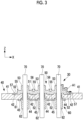
- the plate-like insulating portion 51 includes the insulating protrusions 55 in the present embodiment. Accordingly, a creepage distance between the terminal 70 and the base part 40 is a distance bypassing the insulating protrusion 55 as shown by an arrow A1 shown in Fig. 3 . Therefore, a creepage distance between the terminal 70 and the base part 40 can be increased as compared to a case where the insulating protrusion 55 is not provided. Accordingly, an insulating property can be improved.
- the upper insulating member 50 and the lower insulating member 60 are made of HNBR has been described in the embodiment, but the present disclosure is not limited thereto.
- the lower insulating member 60 which is in contact with a refrigerant during the operation of the electric compressor 1, may be made of HNBR
- the upper insulating member 50 which is less likely to be in contact with a refrigerant during the operation, may be made of silicone rubber.
- the terminal unit 30 is fixed to be in contact with the lower surface of the bottom surface part 28 of the first inverter housing 26 in the embodiment. That is, an example in which the terminal unit 30 is fixed to the first inverter housing 26 such that the base part 40 of the terminal unit 30 is positioned on a refrigerant side (in other words, in the internal space S1 of the housing 2) has been described.
- the present disclosure is not limited thereto.
- the terminal unit 30 may be fixed to be in contact with the upper surface of the bottom surface part 28 of the first inverter housing 26. That is, the terminal unit 30 may be fixed to the first inverter housing 26 such that the base part 40 of the terminal unit 30 is positioned on an atmosphere side (in other words, in the housing space S2 of the inverter housing unit 25).
- terminal unit and the compressor described in the embodiment mentioned above are grasped, for example, as follows.
- a terminal unit includes: a plate-like base part (40); a first insulating portion (51, 52) that covers a plate surface of the base part; a terminal (70) that extends in a predetermined direction (Z-axis direction), which is a direction intersecting the plate surface of the base part, and penetrates the base part and the first insulating portion; and a second insulating portion (53) that extends from the first insulating portion in the predetermined direction and covers a side surface of the terminal.
- the first insulating portion and the second insulating portion are integrally molded.
- the first insulating portion covering the plate surface of the base part is provided. Accordingly, even in a case where a part of the terminal is exposed from the second insulating portion, a creepage distance between an exposed portion of the terminal and the base part is a distance bypassing the first insulating portion. Therefore, a creepage distance between the exposed portion of the terminal and the base part can be increased as compared to a case where the first insulating portion is not provided. Accordingly, an insulating property can be improved.
- first insulating portion and the second insulating portion are integrally molded in the above-mentioned configuration. Accordingly, the number of components can be reduced as compared to a case where the first insulating portion and the second insulating portion are separately manufactured. Therefore, manufacturing work can be facilitated. Furthermore, manufacturing costs can be reduced.
- the first insulating portion includes a sealing protrusion (57) that is provided over an entire region of an outer edge portion of the first insulating portion in a circumferential direction and protrudes from a surface of the first insulating portion, and the sealing protrusion is made of an elastic material.
- the first insulating portion includes the sealing protrusion made of the elastic material. Accordingly, for example, in a case where the terminal unit is fixed to a fixing target, the sealing protrusion is deformed to be crushed by being pressed against the fixing target. That is, the sealing protrusion is deformed to be in close contact with the fixing target. Therefore, sealing performance between the fixing target and the terminal unit can be improved.
- the base part is made of a metallic material and the base part includes an exposed portion (41) that is exposed from the first insulating portion.
- the base part includes the exposed portion that is exposed from the first insulating portion. Furthermore, the base part is made of a metallic material.
- the exposed portion may be in contact with the fixing target and the exposed portion and the fixing target may be fixed to each other by a fastener.
- the exposed portion and the fixing target are in contact with each other without using a material (for example, a rubber material or the like) having an elastic modulus higher than the elastic modulus of a metallic material. Accordingly, it is possible to make it difficult to reduce the axial force of the fastener that fastens the exposed portion to the fixing target. Therefore, the base part and the fixing target can be firmly fixed to each other. Accordingly, a decrease in sealing performance between the base part and the fixing target can be suppressed.
- At least one of the first insulating portion or the second insulating portion is made of an elastic material.
- At least one of the first insulating portion or the second insulating portion is made of the elastic material. Accordingly, for example, in a case where the terminal unit is fixed to the fixing target, the first insulating portion or the second insulating portion made of the elastic material is pressed against the fixing target, so that the first insulating portion or the second insulating portion, which is pressed, is deformed to be in close contact with the fixing target. Therefore, sealing performance between the fixing target and the terminal unit can be improved.
- the elastic material examples include materials (for example, a rubber material, a resin material, and the like) having an elastic modulus higher than the elastic modulus of metal.
- the first insulating portion includes an insulating protrusion (55) that protrudes from a surface of the first insulating portion.
- the first insulating portion includes the insulating protrusion. Accordingly, a creepage distance between the exposed portion of the terminal and the base part is a distance bypassing the insulating protrusion. Therefore, a creepage distance between the exposed portion of the terminal and the base part can be increased as compared to a case where the insulating protrusion is not provided. Accordingly, an insulating property can be improved.
- a compressor according to an aspect of the present disclosure includes the terminal unit according to any one of the above.
Landscapes
- Engineering & Computer Science (AREA)
- Mechanical Engineering (AREA)
- General Engineering & Computer Science (AREA)
- Power Engineering (AREA)
- Compressor (AREA)
- Motor Or Generator Frames (AREA)
- Applications Or Details Of Rotary Compressors (AREA)
- Connection Of Motors, Electrical Generators, Mechanical Devices, And The Like (AREA)
Abstract
Description
- The present disclosure relates to a terminal unit and a compressor.
- A compressor in which both a compression mechanism for compressing a refrigerant and an electric motor for supplying a drive force to the compression mechanism are housed in a housing is known. In such a compressor, a power supply unit and the electric motor are connected to each other via a connection member to supply power to the electric motor from the power supply unit. Since the power supply unit is disposed outside the housing, an opening through which the connection member is inserted is formed in the housing.
-
PTL 1 discloses a compressor in which a stator coil is electrically connected to a motor drive circuit provided outside a housing via a connection device. In this compressor, a lead wire extends from the stator coil. Further, the lead wire is inserted through a through-hole formed in an end cover, and is led to the outside of an end cover. - [PTL 1]
Japanese Unexamined Patent Application Publication No. 2006-291926 - Incidentally, there is a compressor in which a terminal is inserted through an opening of a housing. Since the lead wire is inserted through the opening as described above in a structure disclosed in
PTL 1, a structure in which a terminal is inserted through an opening is not considered. - In a compressor in which a terminal is inserted through an opening of a housing, it is necessary to insulate the terminal to suppress the leakage of current flowing through the terminal. Since various problems occur in a case where current flowing through the terminal leaks, it is desired to improve the insulating property of the terminal.
- The present disclosure has been made in consideration of such circumstances, and an object of the present disclosure is to provide a terminal unit and a compressor that can improve an insulating property.
- In order to achieve the object, a terminal unit and a compressor according to aspects of the present disclosure employ the following means.
- A terminal unit according to an aspect of the present disclosure includes: a plate-like base part; a first insulating portion that covers a plate surface of the base part; a terminal that extends in a predetermined direction, which is a direction intersecting the plate surface of the base part, and penetrates the base part and the first insulating portion; and a second insulating portion that extends from the first insulating portion in the predetermined direction and covers a side surface of the terminal. The first insulating portion and the second insulating portion are integrally molded.
- According to the present disclosure, it is possible to improve an insulating property.
-
-
Fig. 1 is a longitudinal sectional view of a compressor according to an embodiment of the present disclosure. -
Fig. 2 is an enlarged view of a main portion (portion II) ofFig. 1 . -
Fig. 3 is a longitudinal sectional view of a terminal unit provided in the compressor shown inFig. 1 . Description of Embodiments - A terminal unit and a compressor according to an embodiment of the present disclosure will be described below with reference to the drawings.
-
Fig. 1 shows a longitudinal sectional view of an electric compressor (compressor) 1 according to the present embodiment. - The
electric compressor 1 according to the present embodiment is an inverter-integrated electric compressor in which an inverter (not shown) for driving amotor 17 is integrally built. - The
electric compressor 1 includes ahousing 2 that forms an outer shell, ascroll compression mechanism 7 that is housed in thehousing 2, and amotor 17 that drives thescroll compression mechanism 7. - An internal space S1, which houses the
scroll compression mechanism 7, themotor 17, and the like, is formed in thehousing 2. Thehousing 2 is made of, for example, a metallic material. Thehousing 2 includes a cylindricalfirst housing 3 that extends along a central axis, and a second housing 4 that closes one end side (a lower end side inFig. 1 ) of thefirst housing 3 in a direction of the central axis. That is, thefirst housing 3 defines the side of the internal space S1. Further, the second housing 4 defines the lower side of the internal space S1. The upper side of the internal space S1 is defined by aninverter housing unit 25. Details of theinverter housing unit 25 will be described later. - The
scroll compression mechanism 7 is built in on one end side of thehousing 2. Thescroll compression mechanism 7 includes a pair of scrolls, that is, afixed scroll 5 and anorbiting scroll 6. Thescroll compression mechanism 7 compresses refrigerant gas. The high-pressure refrigerant gas compressed by thescroll compression mechanism 7 is discharged into adischarge chamber 10 via a discharge port 8. The discharge port 8 is formed at the center of thefixed scroll 5. The refrigerant gas discharged into thedischarge chamber 10 is discharged to the outside of theelectric compressor 1 via a discharge port (not shown) provided in thehousing 2. - The
fixed scroll 5 is fixed to the second housing 4 by fasteners (not shown), such asbolts 31. The orbitingscroll 6 is supported by a thrust bearing 12 via a rotation prevention mechanism (not shown) such that the orbitingscroll 6 can orbit. The orbiting scroll 6 orbits with respect to thefixed scroll 5. - The
fixed scroll 5 and theorbiting scroll 6 are engaged with each other to mesh with each other. Acompression chamber 14 is formed between thefixed scroll 5 and theorbiting scroll 6. In a case where the orbiting scroll 6 orbits (revolves) such that the volume of thecompression chamber 14 is reduced from the outer peripheral side toward the central side, thescroll compression mechanism 7 compresses the refrigerant present in thecompression chamber 14. - The
motor 17 is built in on the other end side of thecylindrical housing 2. Themotor 17 includes astator 15 and arotor 16. Adrive shaft 18 is joined to therotor 16. Thedrive shaft 18 is rotatably supported by abearing 20 that is installed near a central portion in thehousing 2 and a bearing (not shown) that is installed near the other end portion in thehousing 2. Acrank pin 19 is provided at one end of thedrive shaft 18. The central axis of thedrive shaft 18 and the central axis of thecrank pin 19 are eccentric. Thecrank pin 19 is connected to the orbitingscroll 6. That is, thedrive shaft 18 connects themotor 17 and thescroll compression mechanism 7. Themotor 17 causes the orbitingscroll 6 to orbit via thedrive shaft 18. - Further, a driven crank mechanism (not shown) is provided between the
crank pin 19 and theorbiting scroll 6. The driven crank mechanism makes the orbiting radius of theorbiting scroll 6 variable. Examples of the driven crank mechanism include a swing link type driven crank mechanism. - Furthermore, the
motor 17 and the inverter are connected to each other via aterminal unit 30. Details of theterminal unit 30 will be described later. - A suction port (not shown) used to suck low-pressure refrigerant gas discharged from a refrigeration cycle is provided on the other end portion side of the
housing 2. The refrigerant gas sucked from the suction port flows into aspace portion 24 between the second housing 4 and one end of themotor 17. The low-pressure refrigerant gas having flowed into thespace portion 24 fills thehousing 2. Specifically, the low-pressure refrigerant gas having flowed into thespace portion 24 flows toward thescroll compression mechanism 7, is sucked into thescroll compression mechanism 7, and is compressed. A lubricant is contained in the refrigerant gas. The lubricant contained in the refrigerant gas is supplied to thescroll compression mechanism 7 and the rotation prevention mechanism together with the refrigerant gas to lubricate each mechanism. - The
inverter housing unit 25, which houses the inverter, is provided on the other end side (an upper end side inFig. 1 ) of thehousing 2 in a direction along the central axis. The inverter converts DC power, which is supplied from an external battery or the like, into three-phase AC power having a required frequency and applies the three-phase AC power to themotor 17 viaterminals 70 to drive themotor 17. - For example, the inverter includes: a power board on which a switching circuit including a plurality of power transistors, such as IGBT, which is a semiconductor switching element for power, is mounted; a control board on which a control communication circuit including an element, which operates at a low voltage, such as a CPU for controlling the switching circuit and the like, on the basis of control signals input from the outside is mounted; and electrical components such as a smoothing capacitor and a coil forming a filter circuit for removing noise.
- A housing space S2 in which the inverter is housed is formed in the
inverter housing unit 25. Theinverter housing unit 25 is made of, for example, a metallic material. Theinverter housing unit 25 includes afirst inverter housing 26 that defines a lower portion of the housing space S2, and asecond inverter housing 34 that defines an upper portion of the housing space S2. - The
first inverter housing 26 is integrally provided with aside wall part 27 that defines the side of the housing space S2, abottom surface part 28 that defines the lower side of the housing space S2, and aprotrusion part 29 that protrudes downward from a lower surface of thebottom surface part 28. Theside wall part 27 is erected at an outer edge portion of thebottom surface part 28. - The
bottom surface part 28 closes the other end (upper end) side of thefirst housing 3. That is, the lower surface of thebottom surface part 28 defines the upper side of the internal space S1. Anopening 28a is formed in thebottom surface part 28. Theopening 28a connects the internal space S1 and the housing space S2. Thisopening 28a is provided with theterminal unit 30. Further, thebottom surface part 28 includes a bulgingportion 28b that bulges upward. Theopening 28a is formed at the center of the bulgingportion 28b. A plurality of first bolt insertion holes (not shown) through whichbolts 31 are inserted are formed at the bulgingportion 28b. - The
protrusion part 29 is a cylindrical member. An outer peripheral surface of theprotrusion part 29 is in contact with an inner peripheral surface of an opening formed at an upper end of thefirst housing 3. Theprotrusion part 29 is fitted into the opening formed at the upper end of thefirst housing 3. - The
second inverter housing 34 covers the housing space S2 from above. A lower end of thesecond inverter housing 34 is connected to an upper end of theside wall part 27. - Next, details of the
terminal unit 30 will be described. In the following description and drawings, a vertical direction will be referred to as a Z-axis direction and a direction, which is orthogonal to the Z-axis direction and in which threeterminals 70 are lined up, will be referred to as an X-axis direction. - The
terminal unit 30 connects themotor 17 and the inverter, and closes theopening 28a formed in thebottom surface part 28 of thesecond inverter housing 34. - As shown in
Fig. 2 , theterminal unit 30 includes a plate-like base part 40 that covers theopening 28a from below, an upper insulatingmember 50 that is provided on an upper surface of thebase part 40, and a lower insulatingmember 60 that is provided on a lower surface of thebase part 40. Further, theterminal unit 30 includes threeterminals 70 that penetrate thebase part 40, the upper insulatingmember 50, and the lower insulatingmember 60. Furthermore, theterminal unit 30 is fixed to theinverter housing unit 25 by a plurality ofbolts 31. The plurality ofbolts 31 are arranged to surround theopening 28a. Each of thebolts 31 is inserted through the first bolt insertion hole and a second bolt insertion hole. - The
base part 40 is made of a metallic material. As shown inFigs. 2 and3 , thebase part 40 is a flat plate-like member. A fixing portion 41 (exposed portion) is provided at an outer edge portion of thebase part 40. The fixingportion 41 is formed to have a flat upper surface. The fixingportion 41 is not covered with the upper insulatingmember 50. That is, the fixingportion 41 is exposed from the upper insulatingmember 50. The upper surface of the fixingportion 41 is in surface contact with a lower surface of the bulgingportion 28b of thefirst inverter housing 26. Second bolt insertion holes (not shown) penetrating in a plate thickness direction are formed in the fixingportion 41. Thebolts 31 are inserted through the second bolt insertion holes. - Further, a plurality of (for example, four in the present embodiment) recessed
portions 42, which are recessed downward, are formed at a central portion of the upper surface of thebase part 40. The plurality of recessedportions 42 are arranged side by side at regular intervals in the X-axis direction. Fitting insulatingportions 52 of the upper insulatingmember 50 to be described later are fitted into the recessedportions 42. A part of the recessedportions 42 disposed at both ends in the X-axis direction overlap the bulgingportion 28b as viewed in a plan view. - A terminal through-hole penetrating in the plate thickness direction is formed in the
base part 40 between the adjacent recessedportions 42. That is, three terminal through-holes are formed in the present embodiment. The three terminal through-holes are arranged side by side at predetermined intervals in the X-axis direction. A cylindrical member 44 (seeFig. 3 ) made of a glass material is fitted into each terminal through-hole. An inner peripheral surface of the terminal through-hole and an outer peripheral surface of thecylindrical member 44 are in contact with each other. Aflange portion 45 extending outward in a radial direction is provided at a lower end portion of thecylindrical member 44. The terminal 70 is inserted through the inside of thecylindrical member 44. An inner peripheral surface of thecylindrical member 44 and an outer peripheral surface of the terminal 70 are in contact with each other. The terminal 70 is inserted through the terminal through-hole via thecylindrical member 44. The shape of thecylindrical member 44 is not limited to the shape described in the present embodiment. For example, theflange portion 45 may be omitted. - The upper surface of the
base part 40 is covered with the upper insulatingmember 50. Specifically, an upper surface of a portion of thebase part 40 other than the fixingportion 41 is covered with the upper insulatingmember 50. - Step sections, which are recessed upward, are formed on the lower surface of the
base part 40. The step section is fitted to theflange portion 45 of thecylindrical member 44. A central portion of the lower surface of thebase part 40 is covered with the lower insulatingmember 60. In a case where theflange portions 45 are not present on thecylindrical members 44, the step sections may not be formed. - The upper insulating
member 50 is made of an insulating rubber material (for example, hydrogenated nitrile rubber (HNBR)). That is, the upper insulatingmember 50 is made of an elastic material having an elastic modulus higher than the elastic modulus of metal. The material of the upper insulatingmember 50 is not limited to HNBR. The upper insulatingmember 50 includes a plate-like insulating portion (first insulating portion) 51 that covers the upper surface of thebase part 40, fitting insulating portions (first insulating portion) 52 that protrude downward from a lower surface of the plate-like insulatingportion 51, and three upper cylindrical insulating portions (second insulating portion) 53 that extend upward from the plate-like insulatingportion 51. The plate-like insulatingportion 51, the upper cylindrical insulatingportions 53, and the fitting insulatingportions 52 are integrally molded. Specifically, the plate-like insulatingportion 51, the upper cylindrical insulatingportions 53, and the fitting insulatingportions 52 are not members that are separately manufactured and fixed to each other, but are molded as an integral body by, for example, injection molding or the like. - The plate-like insulating
portion 51 is placed on the upper surface of thebase part 40. That is, the lower surface of the plate-like insulatingportion 51 is in surface contact with the upper surface of thebase part 40. Three upper through-holes penetrating in the plate thickness direction are formed in the plate-like insulatingportion 51. The three upper through-holes are arranged side by side at predetermined intervals in the X-axis direction. Upper ends of the upper through-holes are connected to spaces formed in the upper cylindrical insulatingportions 53. Further, lower ends of the upper through-holes are connected to spaces formed in thecylindrical members 44. Theterminals 70 are inserted through the upper through-holes. - Furthermore, the plate-like insulating
portion 51 includes a plurality of insulatingprotrusions 55 that protrude upward from the upper surface of the plate-like insulatingportion 51. Each of the insulatingprotrusions 55 is erected to surround the upper cylindrical insulatingportion 53. The insulatingprotrusion 55 is disposed outside the upper cylindrical insulatingportion 53 in a radial direction, and is provided over the entire region of the upper cylindrical insulatingportion 53 in a circumferential direction. Upper ends of the insulatingprotrusions 55 are positioned below an upper end of the bulgingportion 28b. Further, the plate-like insulatingportion 51 includes insulating recessedportions 56 each of which is formed between the adjacent insulatingprotrusions 55. The insulating recessedportions 56 are recessed downward from the upper surface of the plate-like insulatingportion 51. - The three upper cylindrical insulating
portions 53 are arranged side by side at predetermined intervals in the X-axis direction. Each upper cylindrical portion insulating portion covers the side surface of the terminal 70. Specifically, each upper cylindrical insulatingportion 53 covers a partial region of the side surface of the terminal 70 in the vertical direction. Upper ends of the upper cylindrical insulatingportions 53 are positioned below the upper end of the bulgingportion 28b. - A plurality of fitting insulating
portions 52 are provided. Each fitting insulatingportion 52 is fitted into the recessedportion 42. In other words, each fitting insulatingportion 52 covers the upper surface and the inner peripheral surface of the recessedportion 42. Each of the fitting insulatingportions 52, which are fitted into the recessedportions 42 disposed at both ends in the X-axis direction, integrally includes a sealing protrusion 57 (seeFig. 3 ) that protrudes upward from the upper surface of the fitting insulatingportion 52. The sealingprotrusion 57 is provided over the entire region of the outer edge portion in the circumferential direction. The sealingprotrusions 57 are provided at positions on the upper surface of the fitting insulatingportion 52 facing the lower surface of the bulgingportion 28b. As shown inFig. 2 , the sealingprotrusions 57 are deformed to be crushed by being pressed against the lower surface of the bulgingportion 28b in a state where theterminal unit 30 is attached to theinverter housing unit 25. - The height of the recessed
portion 42 and the height of the fitting insulatingportion 52 are substantially equal to each other. That is, the fitting insulatingportion 52 is formed not to protrude upward from the recessedportion 42. In other words, the upper surface of the fitting insulatingportion 52 and the upper surface of the fixingportion 41 of thebase part 40 are flush with each other. - The lower insulating
member 60 is made of an insulating rubber material (for example, hydrogenated nitrile rubber (HNBR)). That is, the lower insulatingmember 60 is made of an elastic material having an elastic modulus higher than the elastic modulus of metal. The material of the lower insulatingmember 60 is not limited to HNBR. The lower insulatingmember 60 includes a flat plate-insulatingportion 61 that covers the lower surface of thebase part 40, and three lower cylindrical insulatingportions 62 that extend downward from a lower surface of the flat plate-insulatingportion 61. The flat plate-insulatingportion 61 and the lower cylindrical insulatingportions 62 are integrally molded. Specifically, the flat plate-insulatingportion 61 and the lower cylindrical insulatingportions 62 are not members that are separately manufactured and fixed to each other, but are molded as an integral body by, for example, injection molding or the like. - The lower surface of the flat plate-insulating
portion 61 is in surface contact with the upper surface of thebase part 40. The flat plate-insulatingportion 61 covers only the central portion of the lower surface of thebase part 40. That is, the flat plate-insulatingportion 61 does not cover the outer edge portion of the lower surface of thebase part 40.Nuts 32, which are screwed to thebolts 31, are provided at the outer edge portion of the lower surface of thebase part 40. - Three lower through-holes penetrating in the plate thickness direction are formed in the flat plate-insulating
portion 61. The three lower through-holes are arranged side by side at predetermined intervals in the X-axis direction. Lower ends of the lower through-holes are connected to spaces formed in the lower cylindrical insulatingportions 62. Further, upper ends of the lower through-holes are connected to spaces formed in thecylindrical members 44. Theterminals 70 are inserted through the lower through-holes. - The lower cylindrical insulating
portions 62 are arranged side by side at predetermined intervals in the X-axis direction. Each upper cylindrical portion insulating portion covers the side surface of the terminal 70. Specifically, each lower cylindrical insulatingportion 62 covers the entire region of the side surface of the terminal 70 between astator terminal cover 33 and the flat plate-insulatingportion 61. Lower ends of the lower cylindrical insulatingportions 62 are in contact with an upper surface of thestator terminal cover 33. The lower cylindrical insulatingportions 62 seal between theterminals 70 and a stator terminal (not shown). Further, the lower cylindrical insulatingportion 62 insulates the terminal 70. - The three
terminals 70 are arranged side by side at predetermined intervals in the X-axis direction. Each terminal 70 extends in the vertical direction (Z-axis direction). Each terminal 70 is inserted through the upper cylindrical insulatingportion 53, the upper through-hole, the terminal through-hole (cylindrical member 44), the lower through-hole, and the lower cylindrical insulatingportion 62. Upper portions of theterminals 70 are positioned in the housing space S2 formed in theinverter housing unit 25. Lower portions of theterminals 70 are positioned in the internal space S1 of thehousing 2. Lower end portions of theterminals 70 are disposed in thestator terminal cover 33 disposed above thestator 15. - Upper end portions of the
terminals 70 are connected to the inverter. Further, lower end portions of the terminal 70 are connected to thestator 15. Theterminals 70, the inverter, and thestator 15 may be directly connected to each other or may be indirectly connected to each other via a lead wire or the like. - Actions and effects to be described below will be obtained in the present embodiment.
- The plate-like insulating
portion 51, which covers the plate surface of thebase part 40, and the fitting insulatingportions 52 are provided in the present embodiment. Accordingly, a creepage distance between an exposed portion of the terminal 70 and thebase part 40 is a distance bypassing the plate-like insulatingportion 51 and the fitting insulatingportion 52. Therefore, a creepage distance between the exposed portion of the terminal 70 and thebase part 40 can be increased as compared to a case where the plate-like insulatingportion 51 and the fitting insulatingportion 52 are not provided. Accordingly, an insulating property can be improved. - Further, the flat plate-insulating
portion 61 and the lower cylindrical insulatingportions 62 are integrally molded in the present embodiment. That is, the entire lower insulatingmember 60 is integrally molded. Accordingly, the number of components can be reduced as compared to a case where the flat plate-insulatingportion 61 and the lower cylindrical insulatingportions 62 are separately manufactured. Therefore, manufacturing work can be facilitated. Furthermore, manufacturing costs can be reduced. - Further, in the present embodiment, the plate-like insulating
portion 51, the upper cylindrical insulatingportions 53, and the fitting insulatingportions 52 are integrally molded. That is, the entire upper insulatingmember 50 is integrally molded. Accordingly, the number of components can be reduced as compared to a case where the plate-like insulatingportion 51, the upper cylindrical insulatingportions 53, and the fitting insulatingportions 52 are separately manufactured. Therefore, manufacturing work can be facilitated. Furthermore, manufacturing costs can be reduced. - Furthermore, the internal space S1 formed in the
housing 2 is filled with refrigerant gas. For this reason, it is necessary to seal theopening 28a, which is formed in theinverter housing unit 25, to suppress the leakage of refrigerant gas from the internal space S1 to the housing space S2. - In the present embodiment, the fitting insulating
portions 52 include the sealingprotrusions 57. Accordingly, in a case where theterminal unit 30 is fixed to the housing (fixing target) 2, the sealingprotrusions 57 are pressed against thehousing 2 and are deformed to be crushed. That is, the sealingprotrusions 57 are deformed to be in close contact with thehousing 2. Therefore, sealing performance between the housing 2 (Specifically, the bulgingportion 28b) and the terminal unit 30 (Specifically, the fitting insulating portions 52) can be improved. - As described above, in the present embodiment, portions contributing to sealing and portions contributing to insulation are integrally molded in the upper insulating
member 50 and the lower insulatingmember 60. Accordingly, the number of components can be reduced as compared to a case where members contributing to sealing and members contributing to insulation are separately manufactured. Therefore, manufacturing work can be facilitated and manufacturing costs can be reduced. - Further, in the present embodiment, both the upper insulating
member 50 and the lower insulatingmember 60 are made of a relatively inexpensive rubber material. Accordingly, costs can be reduced as compared to a case where an expensive material (for example, ceramic) is used for the insulation of theterminals 70 and the sealing of theopening 28a. - Further, in the present embodiment, the
base part 40 includes the fixingportion 41 that is exposed from the upper insulatingmember 50. Furthermore, thebase part 40 is made of a metallic material. Moreover, the fixingportion 41 is in surface contact with thehousing 2 and the fixingportion 41 and thehousing 2 are fixed to each other by thebolts 31. As described above, in the present embodiment, the fixingportion 41 and thehousing 2 are in contact with each other without using a material (for example, a rubber material or the like) having an elastic modulus higher than the elastic modulus of a metallic material. Accordingly, it is possible to make it difficult to reduce the axial forces of thebolts 31 that fasten the fixingportion 41 to thehousing 2. Therefore, thebase part 40 and thehousing 2 can be firmly fixed to each other. Accordingly, a decrease in sealing performance between thebase part 40 and thehousing 2 can be suppressed. - Further, the upper insulating
member 50 and the lower insulatingmember 60 are made of a rubber material in the present embodiment. Accordingly, for example, in a case where theterminal unit 30 is fixed to thehousing 2, the upper insulatingmember 50 and the lower insulatingmember 60 are pressed against thehousing 2, so that the upper insulatingmember 50 and the lower insulatingmember 60, which are pressed, are deformed to be in close contact with thehousing 2. Therefore, sealing performance between thehousing 2 and theterminal unit 30 can be improved. - Furthermore, the plate-like insulating
portion 51 includes the insulatingprotrusions 55 in the present embodiment. Accordingly, a creepage distance between the terminal 70 and thebase part 40 is a distance bypassing the insulatingprotrusion 55 as shown by an arrow A1 shown inFig. 3 . Therefore, a creepage distance between the terminal 70 and thebase part 40 can be increased as compared to a case where the insulatingprotrusion 55 is not provided. Accordingly, an insulating property can be improved. - The present disclosure is not limited to the invention according to each embodiment described above, and can be appropriately modified without departing from the scope of the present disclosure.
- For example, an example in which the upper insulating
member 50 and the lower insulatingmember 60 are made of HNBR has been described in the embodiment, but the present disclosure is not limited thereto. For example, the lower insulatingmember 60, which is in contact with a refrigerant during the operation of theelectric compressor 1, may be made of HNBR, and the upper insulatingmember 50, which is less likely to be in contact with a refrigerant during the operation, may be made of silicone rubber. - Further, an example in which the
terminal unit 30 is fixed to be in contact with the lower surface of thebottom surface part 28 of thefirst inverter housing 26 has been described in the embodiment. That is, an example in which theterminal unit 30 is fixed to thefirst inverter housing 26 such that thebase part 40 of theterminal unit 30 is positioned on a refrigerant side (in other words, in the internal space S1 of the housing 2) has been described. However, the present disclosure is not limited thereto. For example, theterminal unit 30 may be fixed to be in contact with the upper surface of thebottom surface part 28 of thefirst inverter housing 26. That is, theterminal unit 30 may be fixed to thefirst inverter housing 26 such that thebase part 40 of theterminal unit 30 is positioned on an atmosphere side (in other words, in the housing space S2 of the inverter housing unit 25). - The terminal unit and the compressor described in the embodiment mentioned above are grasped, for example, as follows.
- A terminal unit according to an aspect of the present disclosure includes: a plate-like base part (40); a first insulating portion (51, 52) that covers a plate surface of the base part; a terminal (70) that extends in a predetermined direction (Z-axis direction), which is a direction intersecting the plate surface of the base part, and penetrates the base part and the first insulating portion; and a second insulating portion (53) that extends from the first insulating portion in the predetermined direction and covers a side surface of the terminal. The first insulating portion and the second insulating portion are integrally molded.
- In the above-mentioned configuration, the first insulating portion covering the plate surface of the base part is provided. Accordingly, even in a case where a part of the terminal is exposed from the second insulating portion, a creepage distance between an exposed portion of the terminal and the base part is a distance bypassing the first insulating portion. Therefore, a creepage distance between the exposed portion of the terminal and the base part can be increased as compared to a case where the first insulating portion is not provided. Accordingly, an insulating property can be improved.
- Further, the first insulating portion and the second insulating portion are integrally molded in the above-mentioned configuration. Accordingly, the number of components can be reduced as compared to a case where the first insulating portion and the second insulating portion are separately manufactured. Therefore, manufacturing work can be facilitated. Furthermore, manufacturing costs can be reduced.
- Furthermore, in the terminal unit according to the aspect of the present disclosure, the first insulating portion includes a sealing protrusion (57) that is provided over an entire region of an outer edge portion of the first insulating portion in a circumferential direction and protrudes from a surface of the first insulating portion, and the sealing protrusion is made of an elastic material.
- In the above-mentioned configuration, the first insulating portion includes the sealing protrusion made of the elastic material. Accordingly, for example, in a case where the terminal unit is fixed to a fixing target, the sealing protrusion is deformed to be crushed by being pressed against the fixing target. That is, the sealing protrusion is deformed to be in close contact with the fixing target. Therefore, sealing performance between the fixing target and the terminal unit can be improved.
- Further, in the terminal unit according to the aspect of the present disclosure, the base part is made of a metallic material and the base part includes an exposed portion (41) that is exposed from the first insulating portion.
- In the above-mentioned configuration, the base part includes the exposed portion that is exposed from the first insulating portion. Furthermore, the base part is made of a metallic material.
- For example, in a case where the terminal unit is fixed to the fixing target, the exposed portion may be in contact with the fixing target and the exposed portion and the fixing target may be fixed to each other by a fastener. In this case, in the above-mentioned configuration, the exposed portion and the fixing target are in contact with each other without using a material (for example, a rubber material or the like) having an elastic modulus higher than the elastic modulus of a metallic material. Accordingly, it is possible to make it difficult to reduce the axial force of the fastener that fastens the exposed portion to the fixing target. Therefore, the base part and the fixing target can be firmly fixed to each other. Accordingly, a decrease in sealing performance between the base part and the fixing target can be suppressed.
- Further, in the terminal unit according to the aspect of the present disclosure, at least one of the first insulating portion or the second insulating portion is made of an elastic material.
- In the above-mentioned configuration, at least one of the first insulating portion or the second insulating portion is made of the elastic material. Accordingly, for example, in a case where the terminal unit is fixed to the fixing target, the first insulating portion or the second insulating portion made of the elastic material is pressed against the fixing target, so that the first insulating portion or the second insulating portion, which is pressed, is deformed to be in close contact with the fixing target. Therefore, sealing performance between the fixing target and the terminal unit can be improved.
- Examples of the elastic material include materials (for example, a rubber material, a resin material, and the like) having an elastic modulus higher than the elastic modulus of metal.
- Further, in the terminal unit according to the aspect of the present disclosure, the first insulating portion includes an insulating protrusion (55) that protrudes from a surface of the first insulating portion.
- In the above-mentioned configuration, the first insulating portion includes the insulating protrusion. Accordingly, a creepage distance between the exposed portion of the terminal and the base part is a distance bypassing the insulating protrusion. Therefore, a creepage distance between the exposed portion of the terminal and the base part can be increased as compared to a case where the insulating protrusion is not provided. Accordingly, an insulating property can be improved.
- A compressor according to an aspect of the present disclosure includes the terminal unit according to any one of the above.
-
- 1: electric compressor (compressor)
- 2: housing
- 3: first housing
- 4: second housing
- 5: fixed scroll
- 6: orbiting scroll
- 7: scroll compression mechanism
- 8: discharge port
- 10: discharge chamber
- 12: thrust bearing
- 14: compression chamber
- 15: stator
- 16: rotor
- 17: motor
- 18: drive shaft
- 19: crank pin
- 20: bearing
- 24: space portion
- 25: inverter housing unit
- 26: first inverter housing
- 27: side wall part
- 28: bottom surface part
- 28a: opening
- 28b: bulging portion
- 29: protrusion part
- 30: terminal unit
- 31: bolt
- 32: nut
- 33: stator terminal cover
- 34: second inverter housing
- 40: base part
- 41: fixing portion
- 42: recessed portion
- 44: cylindrical member
- 45: flange portion
- 50: upper insulating member
- 51: plate-like insulating portion (first insulating portion)
- 52: fitting insulating portion (first insulating portion)
- 53: upper cylindrical insulating portion (second insulating portion)
- 55: insulating protrusion
- 56: insulating recessed portion
- 57: sealing protrusion
- 60: lower insulating member
- 61: flat plate-insulating portion
- 62: lower cylindrical insulating portion
- 70: terminal
- S1: internal space
- S2: housing space
Claims (6)
- A terminal unit comprising:a plate-like base part;a first insulating portion that covers a plate surface of the base part;a terminal that extends in a predetermined direction, which is a direction intersecting the plate surface of the base part, and penetrates the base part and the first insulating portion; anda second insulating portion that extends from the first insulating portion in the predetermined direction and covers a side surface of the terminal,wherein the first insulating portion and the second insulating portion are integrally molded.
- The terminal unit according to Claim 1,wherein the first insulating portion includes a sealing protrusion that is provided over an entire region of an outer edge portion of the first insulating portion in a circumferential direction and protrudes from a surface of the first insulating portion, andthe sealing protrusion is made of an elastic material.
- The terminal unit according to Claim 1 or 2,wherein the base part is made of a metallic material, andthe base part includes an exposed portion that is exposed from the first insulating portion.
- The terminal unit according to any one of Claims 1 to 3,
wherein at least one of the first insulating portion or the second insulating portion is made of an elastic material. - The terminal unit according to any one of Claims 1 to 4,
wherein the first insulating portion includes an insulating protrusion that protrudes from a surface of the first insulating portion. - A compressor comprising:
the terminal unit according to any one of Claims 1 to 5.
Applications Claiming Priority (2)
| Application Number | Priority Date | Filing Date | Title |
|---|---|---|---|
| JP2021018908A JP7657600B2 (en) | 2021-02-09 | 2021-02-09 | Electric Compressor |
| PCT/JP2022/001860 WO2022172712A1 (en) | 2021-02-09 | 2022-01-19 | Terminal unit and compressor |
Publications (2)
| Publication Number | Publication Date |
|---|---|
| EP4277090A1 true EP4277090A1 (en) | 2023-11-15 |
| EP4277090A4 EP4277090A4 (en) | 2024-07-17 |
Family
ID=82796143
Family Applications (1)
| Application Number | Title | Priority Date | Filing Date |
|---|---|---|---|
| EP22752544.1A Withdrawn EP4277090A4 (en) | 2021-02-09 | 2022-01-19 | TERMINAL AND COMPRESSOR UNIT |
Country Status (5)
| Country | Link |
|---|---|
| US (1) | US20240117801A1 (en) |
| EP (1) | EP4277090A4 (en) |
| JP (1) | JP7657600B2 (en) |
| CN (2) | CN116830429A (en) |
| WO (1) | WO2022172712A1 (en) |
Families Citing this family (3)
| Publication number | Priority date | Publication date | Assignee | Title |
|---|---|---|---|---|
| DE102023120482A1 (en) * | 2022-10-28 | 2024-05-08 | Hanon Systems | Sealing arrangement for a device for driving a compressor and device for driving a compressor and a method for producing a connecting arrangement |
| DE102023126911A1 (en) * | 2022-11-23 | 2024-05-23 | Hanon Systems | Sealing arrangement of a device for driving a compressor |
| KR102627862B1 (en) * | 2023-03-15 | 2024-01-23 | (주)천인이엠 | Main terminal assembly for high voltage motor with integrally structured connector |
Family Cites Families (8)
| Publication number | Priority date | Publication date | Assignee | Title |
|---|---|---|---|---|
| JP3203193B2 (en) * | 1996-10-31 | 2001-08-27 | 三洋電機株式会社 | Weatherproof motor unit |
| DE102004040072B4 (en) * | 2004-08-18 | 2009-06-25 | Continental Automotive Gmbh | Sealing arrangement of a piezoelectric actuator and method for sealing a piezoelectric actuator |
| JP4829521B2 (en) | 2005-04-14 | 2011-12-07 | サンデン株式会社 | Scroll type fluid machinery |
| JP4570518B2 (en) * | 2005-06-21 | 2010-10-27 | 株式会社山田製作所 | Resin pump |
| JP4843378B2 (en) * | 2006-05-22 | 2011-12-21 | 日本電産サンキョー株式会社 | Actuator |
| DE102008000598A1 (en) * | 2008-03-11 | 2009-09-17 | Robert Bosch Gmbh | Electrical connection for an electric motor |
| DE102013217977A1 (en) * | 2013-09-09 | 2015-03-12 | Brose Fahrzeugteile GmbH & Co. Kommanditgesellschaft, Würzburg | Arrangement for producing an electrical contact, electric drive, and method |
| JP6311996B2 (en) * | 2015-06-26 | 2018-04-18 | パナソニックIpマネジメント株式会社 | CAND MOTOR PUMP AND MANUFACTURING METHOD FOR CAND MOTOR PUMP |
-
2021
- 2021-02-09 JP JP2021018908A patent/JP7657600B2/en active Active
-
2022
- 2022-01-19 CN CN202280013996.2A patent/CN116830429A/en active Pending
- 2022-01-19 WO PCT/JP2022/001860 patent/WO2022172712A1/en not_active Ceased
- 2022-01-19 EP EP22752544.1A patent/EP4277090A4/en not_active Withdrawn
- 2022-01-19 US US18/276,160 patent/US20240117801A1/en active Pending
- 2022-02-07 CN CN202220250532.0U patent/CN217216223U/en active Active
Also Published As
| Publication number | Publication date |
|---|---|
| CN116830429A (en) | 2023-09-29 |
| US20240117801A1 (en) | 2024-04-11 |
| JP7657600B2 (en) | 2025-04-07 |
| JP2022121919A (en) | 2022-08-22 |
| WO2022172712A1 (en) | 2022-08-18 |
| EP4277090A4 (en) | 2024-07-17 |
| CN217216223U (en) | 2022-08-16 |
Similar Documents
| Publication | Publication Date | Title |
|---|---|---|
| US20240117801A1 (en) | Terminal unit and compressor | |
| CN102132042B (en) | Electric compressor | |
| US8956129B2 (en) | Electric compressor | |
| CN100564875C (en) | motor driven compressor | |
| CN111120249A (en) | Electric compressor | |
| WO2007077857A1 (en) | Electric compressor | |
| CN218235375U (en) | Electric compressor | |
| US8829747B2 (en) | Electric compressor for car air conditioning | |
| US20250146484A1 (en) | Electric compressor | |
| KR20220127746A (en) | electric compressor | |
| EP1867874A1 (en) | Electric motor-driven compressor | |
| US11661944B2 (en) | Electric compressor | |
| CN115143110A (en) | Fluid machinery | |
| EP4138275A1 (en) | A cover for a housing of an electric machine | |
| US20260139674A1 (en) | Electric compressor | |
| US20250215869A1 (en) | Inverter-integrated electric compressor | |
| JP2026031074A (en) | Electric compressor | |
| US20260104187A1 (en) | Electric compressor | |
| JP2024060651A (en) | Electric Compressor | |
| JP2026031078A (en) | Electric compressor | |
| WO2022113974A1 (en) | An electric machine | |
| JP2025118219A (en) | Electric compressor | |
| KR20240156188A (en) | Elecrtic compressor | |
| CN119317778A (en) | Electric compressor and method for manufacturing the same | |
| CN120332130A (en) | Electric compressor |
Legal Events
| Date | Code | Title | Description |
|---|---|---|---|
| STAA | Information on the status of an ep patent application or granted ep patent |
Free format text: STATUS: THE INTERNATIONAL PUBLICATION HAS BEEN MADE |
|
| PUAI | Public reference made under article 153(3) epc to a published international application that has entered the european phase |
Free format text: ORIGINAL CODE: 0009012 |
|
| STAA | Information on the status of an ep patent application or granted ep patent |
Free format text: STATUS: REQUEST FOR EXAMINATION WAS MADE |
|
| 17P | Request for examination filed |
Effective date: 20230807 |
|
| AK | Designated contracting states |
Kind code of ref document: A1 Designated state(s): AL AT BE BG CH CY CZ DE DK EE ES FI FR GB GR HR HU IE IS IT LI LT LU LV MC MK MT NL NO PL PT RO RS SE SI SK SM TR |
|
| DAV | Request for validation of the european patent (deleted) | ||
| DAX | Request for extension of the european patent (deleted) | ||
| A4 | Supplementary search report drawn up and despatched |
Effective date: 20240618 |
|
| RIC1 | Information provided on ipc code assigned before grant |
Ipc: H02K 5/12 20060101ALI20240612BHEP Ipc: H02K 3/50 20060101ALI20240612BHEP Ipc: F04C 23/00 20060101ALI20240612BHEP Ipc: F04C 18/02 20060101ALI20240612BHEP Ipc: F04B 39/12 20060101ALI20240612BHEP Ipc: F04B 39/00 20060101ALI20240612BHEP Ipc: F04B 35/04 20060101ALI20240612BHEP Ipc: H02K 5/22 20060101AFI20240612BHEP |
|
| STAA | Information on the status of an ep patent application or granted ep patent |
Free format text: STATUS: THE APPLICATION HAS BEEN WITHDRAWN |
|
| 18W | Application withdrawn |
Effective date: 20251107 |