EP4277082A1 - Control method, and control system for a substation - Google Patents
Control method, and control system for a substation Download PDFInfo
- Publication number
- EP4277082A1 EP4277082A1 EP22173037.7A EP22173037A EP4277082A1 EP 4277082 A1 EP4277082 A1 EP 4277082A1 EP 22173037 A EP22173037 A EP 22173037A EP 4277082 A1 EP4277082 A1 EP 4277082A1
- Authority
- EP
- European Patent Office
- Prior art keywords
- merging unit
- ied
- control
- substation
- conditional
- Prior art date
- Legal status (The legal status is an assumption and is not a legal conclusion. Google has not performed a legal analysis and makes no representation as to the accuracy of the status listed.)
- Granted
Links
Images

Classifications
-
- H—ELECTRICITY
- H02—GENERATION; CONVERSION OR DISTRIBUTION OF ELECTRIC POWER
- H02J—ELECTRIC POWER NETWORKS; CIRCUIT ARRANGEMENTS OR SYSTEMS FOR SUPPLYING OR DISTRIBUTING ELECTRIC POWER; SYSTEMS FOR STORING ELECTRIC ENERGY
- H02J3/00—Circuit arrangements for AC mains or AC distribution networks
- H02J3/001—Arrangements for handling faults or abnormalities, e.g. emergencies or contingencies
- H02J3/0012—Arrangements for handling faults or abnormalities, e.g. emergencies or contingencies characterised by the contingency detection means in AC networks, e.g. using phasor measurement units [PMU], synchrophasors or contingency analysis
-
- H—ELECTRICITY
- H02—GENERATION; CONVERSION OR DISTRIBUTION OF ELECTRIC POWER
- H02J—ELECTRIC POWER NETWORKS; CIRCUIT ARRANGEMENTS OR SYSTEMS FOR SUPPLYING OR DISTRIBUTING ELECTRIC POWER; SYSTEMS FOR STORING ELECTRIC ENERGY
- H02J3/00—Circuit arrangements for AC mains or AC distribution networks
- H02J3/001—Arrangements for handling faults or abnormalities, e.g. emergencies or contingencies
-
- G—PHYSICS
- G08—SIGNALLING
- G08C—TRANSMISSION SYSTEMS FOR MEASURED VALUES, CONTROL OR SIMILAR SIGNALS
- G08C19/00—Electric signal transmission systems
-
- H—ELECTRICITY
- H02—GENERATION; CONVERSION OR DISTRIBUTION OF ELECTRIC POWER
- H02H—EMERGENCY PROTECTIVE CIRCUIT ARRANGEMENTS
- H02H1/00—Details of emergency protective circuit arrangements
- H02H1/0061—Details of emergency protective circuit arrangements concerning transmission of signals
-
- H—ELECTRICITY
- H02—GENERATION; CONVERSION OR DISTRIBUTION OF ELECTRIC POWER
- H02J—ELECTRIC POWER NETWORKS; CIRCUIT ARRANGEMENTS OR SYSTEMS FOR SUPPLYING OR DISTRIBUTING ELECTRIC POWER; SYSTEMS FOR STORING ELECTRIC ENERGY
- H02J13/00—Circuit arrangements for providing remote monitoring or remote control of equipment in a power distribution network
- H02J13/10—Circuit arrangements for providing remote monitoring or remote control of equipment in a power distribution network characterised by displaying of information or by user interaction, e.g. supervisory control and data acquisition [SCADA] systems
-
- H—ELECTRICITY
- H02—GENERATION; CONVERSION OR DISTRIBUTION OF ELECTRIC POWER
- H02J—ELECTRIC POWER NETWORKS; CIRCUIT ARRANGEMENTS OR SYSTEMS FOR SUPPLYING OR DISTRIBUTING ELECTRIC POWER; SYSTEMS FOR STORING ELECTRIC ENERGY
- H02J13/00—Circuit arrangements for providing remote monitoring or remote control of equipment in a power distribution network
- H02J13/12—Monitoring network conditions, e.g. electrical magnitudes or operational status
-
- H—ELECTRICITY
- H02—GENERATION; CONVERSION OR DISTRIBUTION OF ELECTRIC POWER
- H02J—ELECTRIC POWER NETWORKS; CIRCUIT ARRANGEMENTS OR SYSTEMS FOR SUPPLYING OR DISTRIBUTING ELECTRIC POWER; SYSTEMS FOR STORING ELECTRIC ENERGY
- H02J13/00—Circuit arrangements for providing remote monitoring or remote control of equipment in a power distribution network
- H02J13/13—Circuit arrangements for providing remote monitoring or remote control of equipment in a power distribution network characterised by the transmission of data to equipment in the power network
- H02J13/1321—Circuit arrangements for providing remote monitoring or remote control of equipment in a power distribution network characterised by the transmission of data to equipment in the power network using a wired telecommunication network or a data transmission bus
-
- H—ELECTRICITY
- H02—GENERATION; CONVERSION OR DISTRIBUTION OF ELECTRIC POWER
- H02J—ELECTRIC POWER NETWORKS; CIRCUIT ARRANGEMENTS OR SYSTEMS FOR SUPPLYING OR DISTRIBUTING ELECTRIC POWER; SYSTEMS FOR STORING ELECTRIC ENERGY
- H02J13/00—Circuit arrangements for providing remote monitoring or remote control of equipment in a power distribution network
- H02J13/13—Circuit arrangements for providing remote monitoring or remote control of equipment in a power distribution network characterised by the transmission of data to equipment in the power network
- H02J13/1337—Circuit arrangements for providing remote monitoring or remote control of equipment in a power distribution network characterised by the transmission of data to equipment in the power network involving the use of Internet protocols
-
- H—ELECTRICITY
- H02—GENERATION; CONVERSION OR DISTRIBUTION OF ELECTRIC POWER
- H02J—ELECTRIC POWER NETWORKS; CIRCUIT ARRANGEMENTS OR SYSTEMS FOR SUPPLYING OR DISTRIBUTING ELECTRIC POWER; SYSTEMS FOR STORING ELECTRIC ENERGY
- H02J13/00—Circuit arrangements for providing remote monitoring or remote control of equipment in a power distribution network
- H02J13/14—Circuit arrangements for providing remote monitoring or remote control of equipment in a power distribution network the power network being locally controlled, e.g. home energy management systems [HEMS]
-
- H—ELECTRICITY
- H02—GENERATION; CONVERSION OR DISTRIBUTION OF ELECTRIC POWER
- H02J—ELECTRIC POWER NETWORKS; CIRCUIT ARRANGEMENTS OR SYSTEMS FOR SUPPLYING OR DISTRIBUTING ELECTRIC POWER; SYSTEMS FOR STORING ELECTRIC ENERGY
- H02J13/00—Circuit arrangements for providing remote monitoring or remote control of equipment in a power distribution network
- H02J13/18—Circuit arrangements for providing remote monitoring or remote control of equipment in a power distribution network characterised by the remotely-controlled equipment, e.g. converters or transformers
- H02J13/333—Circuit arrangements for providing remote monitoring or remote control of equipment in a power distribution network characterised by the remotely-controlled equipment, e.g. converters or transformers the equipment forming part of substations
-
- H—ELECTRICITY
- H02—GENERATION; CONVERSION OR DISTRIBUTION OF ELECTRIC POWER
- H02J—ELECTRIC POWER NETWORKS; CIRCUIT ARRANGEMENTS OR SYSTEMS FOR SUPPLYING OR DISTRIBUTING ELECTRIC POWER; SYSTEMS FOR STORING ELECTRIC ENERGY
- H02J13/00—Circuit arrangements for providing remote monitoring or remote control of equipment in a power distribution network
- H02J13/18—Circuit arrangements for providing remote monitoring or remote control of equipment in a power distribution network characterised by the remotely-controlled equipment, e.g. converters or transformers
- H02J13/34—Circuit arrangements for providing remote monitoring or remote control of equipment in a power distribution network characterised by the remotely-controlled equipment, e.g. converters or transformers the equipment being switches, relays or circuit breakers
-
- H—ELECTRICITY
- H04—ELECTRIC COMMUNICATION TECHNIQUE
- H04L—TRANSMISSION OF DIGITAL INFORMATION, e.g. TELEGRAPHIC COMMUNICATION
- H04L12/00—Data switching networks
- H04L12/28—Data switching networks characterised by path configuration, e.g. LAN [Local Area Networks] or WAN [Wide Area Networks]
- H04L12/40—Bus networks
- H04L12/40006—Architecture of a communication node
-
- H—ELECTRICITY
- H04—ELECTRIC COMMUNICATION TECHNIQUE
- H04L—TRANSMISSION OF DIGITAL INFORMATION, e.g. TELEGRAPHIC COMMUNICATION
- H04L69/00—Network arrangements, protocols or services independent of the application payload and not provided for in the other groups of this subclass
- H04L69/26—Special purpose or proprietary protocols or architectures
-
- H—ELECTRICITY
- H04—ELECTRIC COMMUNICATION TECHNIQUE
- H04Q—SELECTING
- H04Q9/00—Arrangements in telecontrol or telemetry systems for selectively calling a substation from a main station, in which substation desired apparatus is selected for applying a control signal thereto or for obtaining measured values therefrom
-
- G—PHYSICS
- G01—MEASURING; TESTING
- G01R—MEASURING ELECTRIC VARIABLES; MEASURING MAGNETIC VARIABLES
- G01R19/00—Arrangements for measuring currents or voltages or for indicating presence or sign thereof
- G01R19/25—Arrangements for measuring currents or voltages or for indicating presence or sign thereof using digital measurement techniques
- G01R19/2513—Arrangements for monitoring electric power systems, e.g. power lines or loads; Logging
-
- H—ELECTRICITY
- H02—GENERATION; CONVERSION OR DISTRIBUTION OF ELECTRIC POWER
- H02J—ELECTRIC POWER NETWORKS; CIRCUIT ARRANGEMENTS OR SYSTEMS FOR SUPPLYING OR DISTRIBUTING ELECTRIC POWER; SYSTEMS FOR STORING ELECTRIC ENERGY
- H02J13/00—Circuit arrangements for providing remote monitoring or remote control of equipment in a power distribution network
- H02J13/18—Circuit arrangements for providing remote monitoring or remote control of equipment in a power distribution network characterised by the remotely-controlled equipment, e.g. converters or transformers
- H02J13/34—Circuit arrangements for providing remote monitoring or remote control of equipment in a power distribution network characterised by the remotely-controlled equipment, e.g. converters or transformers the equipment being switches, relays or circuit breakers
- H02J13/36—Circuit arrangements for providing remote monitoring or remote control of equipment in a power distribution network characterised by the remotely-controlled equipment, e.g. converters or transformers the equipment being switches, relays or circuit breakers specially adapted for protection systems
-
- H—ELECTRICITY
- H04—ELECTRIC COMMUNICATION TECHNIQUE
- H04Q—SELECTING
- H04Q2209/00—Arrangements in telecontrol or telemetry systems
- H04Q2209/30—Arrangements in telecontrol or telemetry systems using a wired architecture
-
- Y—GENERAL TAGGING OF NEW TECHNOLOGICAL DEVELOPMENTS; GENERAL TAGGING OF CROSS-SECTIONAL TECHNOLOGIES SPANNING OVER SEVERAL SECTIONS OF THE IPC; TECHNICAL SUBJECTS COVERED BY FORMER USPC CROSS-REFERENCE ART COLLECTIONS [XRACs] AND DIGESTS
- Y02—TECHNOLOGIES OR APPLICATIONS FOR MITIGATION OR ADAPTATION AGAINST CLIMATE CHANGE
- Y02E—REDUCTION OF GREENHOUSE GAS [GHG] EMISSIONS, RELATED TO ENERGY GENERATION, TRANSMISSION OR DISTRIBUTION
- Y02E60/00—Enabling technologies; Technologies with a potential or indirect contribution to GHG emissions mitigation
Definitions
- the disclosure generally relates to a control method for a control system in a substation, and a control system for a substation.
- reaction time has an immediate effect on device equipment and supply security, reaction time referring to the time period between fault occurrence and fault clearance. For instance, overcurrents can build up while a fault occurs, such as a short-circuit, until the fault is resolved by troubleshooting. Thus, length of reaction time has an immediate effect on the magnitude overcurrents build up to. Accordingly, reducing the reaction time for troubleshooting limits the current magnitude.
- Device equipment for fault isolation and restoration such as switchgear
- a central protection device is provided within a substation.
- the device centralizes all protection and control functionality into a single entity on the substation level which allows for a cost-efficient operation.
- the protection device complies with standardized requirements, e.g. IEC 61850, that define communication protocols between the protection device and equipment located within the substation.
- the requirements also define a reaction time, i.e. one-way delay, which must not be exceeded when communicating a control command for troubleshooting. It is, however, favorable to further reduce the reaction time for preserving existing equipment, thereby extending its lifetime, and also for development of new equipment.
- a control method is provided.
- the control method is configured for a control system in a substation.
- the control system comprises a substation feeder, an intelligent electronic device, IED, a merging unit, and BUS network which connects the IED and the merging unit.
- the control method includes providing measurement signals by the substation feeder to the merging unit. Further, the method includes transmitting, by the merging unit, measurement data based on the measurement signals of the substation feeder to the IED via the BUS network, and identifying, by the IED, a fault condition based on the measurement data, the fault condition being indicative of an actual or potentially forthcoming fault.
- the method also comprises transmitting, by the IED, a conditional control command to the merging unit via the BUS network, the conditional control command comprising a control measure and a condition for executing the control measure, determining, by the merging unit, whether the condition of the conditional control command is met, and if so initiating, by the merging unit, the control measure of the substation feeder circuit.
- An IED refers to a real-time protection and control entity of a substation.
- a substation may have multiple decentralized IEDs, or a single, centralized IED. In the latter case, the IED benefits from a more global view spanning multiple/ all merging units, while also providing substation-wide visibility. Yet, a centralized IED forfeits proximity to the sensors and switchgear bay of feeders which implies longer decision paths, including both communication and decision logic, and thereby reaction times.
- the IED may provide a human-machine interface (HMI) for input by a user and displaying and/or providing data to a user.
- HMI human-machine interface
- the IED may also allow for disturbance recordings for the entire substation.
- the IED typically receives measurement data from the merging unit via the BUS network. It includes logic to process the measurement data in order to identify a fault condition and to issue a conditional control command.
- the logic includes both, hardware components, e.g. a microprocessor, and software components. Besides issuing a conditional control command, the IED may also be configured to issue a control command without a condition that the merging unit executes in any case.
- a merging unit refers to an entity which is configured to merging measurement signals from the feeder into measurement data of a standard digital output format.
- the merging unit may include converting analog measurement signals into digital measurement data.
- the merging unit may also include sampling the measurement signal and further data processing, such as filtering.
- the merging unit may provide the measurement data in digital data packets such as IP packets (e.g., TCP/IP packets such as Ethernet frames) for communication over the BUS network.
- IP packets e.g., TCP/IP packets such as Ethernet frames
- the data packets may be unicast, multicast or broadcast frames.
- the BUS network may be an IP packet-based network such as an Ethernet-based network, for instance a local area network (LAN), or internet-based, for instance a wide area network (WAN), the latter using IP in some cases.
- the BUS Network can also be based on other technologies such as MPLS (Multiprotocol Label Switching).
- the condition of the conditional control command typically comprises a control decision model based on the measurement data.
- the decision path between the merging unit and the switchgear bay is generally shorter than between the IED and the switchgear bay. Thus, there may be a reduction in reaction time depending on where the decision model is executed.
- the decision path may be adapted accordingly, for instance in systems with distributed set-ups or non-local components. Therefore, control models are provided that vary with respect to where parts or the entire control model is executed.
- control model relies on communication between the IED and the merging unit which complies to a standard communication protocol, such as the IEC 61850 standard for communication and interoperability in the digital substations.
- the IED may issue the conditional control command complying to a control model defined as Generic Object Oriented Substation Events (GOOSE) by the IEC 61850.
- GOOSE Generic Object Oriented Substation Events
- the conditional command may adhere to one or more of the following characteristics of GOOSE: GOOSE requires the IED to transmit the conditional control commands within a typical period of less than 10 milliseconds (e.g., 3 milliseconds or 4 milliseconds) to the merging unit.
- GOOSE may adhere to a publisher/subscriber model, in which a publisher transmits unacknowledged data to subscribers.
- a GOOSE command may include, for instance, a specified control measure, such as closing a circuit breaker.
- communication between the IED and the merging unit adheres to a hierarchical control model.
- such communication may be implemented as an extension to the above-described GOOSE control model.
- a GOOSE command may be provided with a condition specifying under what condition the merging unit is to carry out the GOOSE command.
- Such an extended GOOSE command may include, for instance, a specified control measure plus a conditional instruction, such as an elapse of a time period to execute the control measure.
- the hierarchical control model may further enable the IED to dynamically transmit small pieces of flexible programming code, referred to herein as codelet, over the BUS network and to install such a codelet at the merging unit.
- codelets are configured to be executed at the merging unit.
- the merging unit processes this codelet to take simple decisions locally.
- Codelets may comprise functionalities such as condition-based status updates, if-else decision trees evaluating multiple signals, or even a trained machine learning model. Also, the codelets may provide a potential action to take.
- the codelets may be generic or tuned to one or more target merging units. As the merging unit is arranged in proximity to the feeder with its sensors and switchgear bay, the decision path and, thereby, the reaction time is reduced.
- the merging unit may provide the measurement data complying to sampled values (SV) or sampled measure values (SMV), the latter being defined by the IEC 61850-9-2 standard.
- the measurement data may be published by the merging unit at a specific rate for a specific grid frequency, for instance at 4000 frames per second for a grid frequency of 50 Hz and 4800 frames per second for 60 Hz.
- SMV may adhere to a publisher/subscriber model, in which a publisher transmits unacknowledged data to subscribers.
- the merging unit typically offers a physical interface to a switchgear bay of the feeder.
- the switchgear bay may be configured for executing a control measure initiated by the merging unit.
- a control measure typically includes an operation, in particular a protective operation, within the substation feeder circuit by the switchgear bay, such as separating a feeder from the substation if the feeder has a fault, or closing a breaker of the substation feeder circuit after a fault is resolved, in particular tripping circuit breakers, or also raising/lowering tap position in order to maintain desired voltage level.
- the switchgear bay may provide the hardware equipment to execute a respective control measure.
- Fault condition being indicative of a potentially forthcoming fault is used herein to describe anomalies in the measurement data, such as a loss of voltage, overcurrent or frequency deviation.
- control system comprises at least one second merging unit and at least one second substation feeder.
- the BUS network connects the IED and the at least one second merging unit.
- the method further comprises providing measurement signals by the at least one second substation feeder to the at least one second merging unit.
- the method also comprises transmitting, by the at least one second merging unit, second measurement data based on the measurement signals of the at least one second substation feeder to the IED via the BUS network.
- the method may further comprise identifying, by the protection device, a second fault condition based on the second measurement data, the fault condition being indicative of a potentially forthcoming fault, and transmitting, by the protection device, a conditional control command to the at least one second merging unit via the BUS network.
- transmitting the conditional control command via the BUS network complies with a hierarchical communication protocol.
- the merging unit is located at a lower hierarchical level than the IED within the hierarchical communication protocol.
- the measurement data may optionally also be transmitted via the BUS network, according to the hierarchical or to a non-hierarchical communication protocol.
- control method further includes encoding the condition of the conditional control command in a codelet by the IED and transmitting the codelet by the IED to the merging unit via the BUS network.
- the method also includes processing the codelet by the merging unit.
- the merging unit may encompass a codelet interpreter for processing the codelet.
- the codelet may include a sequence of instructions that the merging unit executes. Such instructions may include functional statements such as "IF I > 100 A, Trip breaker, ENDIF".
- condition of the conditional control command comprises a specified reaction time period until initiation of the protection measure.
- a "timed” command is issued to execute a specific protection measure after expiration of the set reaction time.
- Devices in substations are typically synchronized and thereby refer to a common time.
- the reaction time of the "timed" command may be calculated based on the common reference frame.
- condition of the conditional control command comprises a specified fault threshold for the measurement data.
- condition comprises a specified fault threshold for the measurement data over a specified time period.
- condition of the conditional control command comprises a zero-crossing condition for a measured current and/or voltage.
- Examples for specifying the condition may consider applications such as zero-point switching of a circuit breaker. Thereby, the merging unit may locally determine the moment when to initiate the control action, that is when an alternating current of the feeder passes through zero. That way, potential switching arcs and other hazards are prevented.
- the measurement signals typically comprise at least one of a voltage signals, current signals, temperature signals, and frequency signals.
- the measurement data typically comprises at least one of a current data, voltage data, and frequency data based on the respective measurement signals.
- control measure further comprises operating at least one switchgear bay of the substation.
- the switchgear bay preferably comprises at least one of a circuit breaker, a disconnector, load switch or switch disconnector.
- the switch disconnector may comprise common switch disconnectors or fuse switch disconnectors. The operating preferably comprising a control action.
- control method further comprises identifying, by the IED, a no-fault condition based on the measurement data, the no-fault condition being indicative of the conditional control command being no longer necessary, and transmitting, by the IED, a cancel command for cancelling the conditional control command to the merging unit.
- a merging unit for a control system for a substation.
- the merging unit comprises a feeder-facing interface for receiving the measurement signals from at least one substation feeder.
- the merging unit also comprises a signal converter for providing measurement data based on the measurement signals of the at least one substation feeder.
- the merging unit has a BUS interface for transmitting the measurement data via a BUS network to an IED and for receiving a conditional control command from the IED.
- the conditional control command comprises a control measure and a condition for executing the control measure.
- the merging unit also comprises logic configured for determining whether the condition of the conditional control command is met, and if so, for initiating the control measure of the substation feeder circuit.
- a control system for a substation comprises at least one substation feeder with sensors for providing measurement signals, at least one merging unit, an IED, and a BUS network.
- the BUS network connects the at least one merging unit with the IED.
- the at least one merging unit has a feeder-facing interface for receiving the measurement signals from the at least one substation feeder, a signal converter for providing measurement data based on the measurement signals of the at least one substation feeder, and a BUS interface for transmitting the measurement data via the BUS network to the IED.
- the IED has a BUS interface for receiving the measurement data.
- the IED has also logic for identifying, based on the measurement data, a fault condition indicative of a potentially forthcoming fault and for providing a conditional control command.
- the BUS interface is configured for transmitting the conditional control command via the BUS network to the at least one merging unit.
- the conditional control command comprises a control measure and a condition for executing the control measure.
- the merging unit has logic configured for determining whether the condition of the conditional control command is met, and if so, for initiating the control measure of the substation feeder circuit.
- the BUS network between the IED and the merging unit complies with a hierarchical communication protocol.
- the at least one merging unit is located at a lower hierarchical level than the IED within the hierarchical communication protocol.
- conditional control command is encoded as a codelet
- the merging unit has logic configured for carrying out the codelet.
- the codelet may be precompiled or created on the fly by the IED.
- the codelet may be generic or targeting a specific merging unit or a group of merging units.
- the codelet may encompass functional statements, a compute graph or machine learning model used to take the decision on a control action.
- control system further comprises at least one switchgear bay.
- the switchgear bay preferably comprises at least one of a circuit breaker, a disconnector, load switch or switch disconnector.
- the control measure preferably comprises a control action.
- the circuit breaker may be a gas-insulated or an air-insulated circuit breaker.
- the switchgear system may be configured for low voltage (up to, e.g. 1 KV), medium voltage (e.g. 3 KV to 36 KV) or high voltage (e.g. above 36 KV).
- the switchgear may use communication standards which are different from the IEC 61850 standard, for instance OPC-UA, MODBUS, IEC 60870, DNP3. These standards may be extended to carry a conditional control command and/or a codelet.
- the control system is further configured for carrying out above-described method or parts thereof.
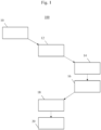
- Fig. 1 illustrates a control method 100 for a control system in a substation.
- the control system and its components which include a substation feeder, an intelligent electronic device, IED, a merging unit, and BUS network connecting the IED and the merging unit are described in more detail with reference to Fig. 3 below.
- Fig. 1 with its horizontal arrangement of boxes is intended to illustrate the control system's component carrying out the respective method step.
- the method step symbolized by the box furthest left is carried out by a substation feeder; the method steps symbolized by the middle boxes are carried out by the merging unit; while the method steps symbolized by the boxed furthest right are carried out by the IED.
- the control method 100 comprises providing measurement signals 10 by the substation feeder to the merging unit.
- the method provides for transmitting, by the merging unit, measurement data based on the measurement signals of the substation feeder to the IED via the BUS network.
- the method foresees identifying 14, by the IED, a fault condition based on the measurement data, the fault condition being indicative of a potentially forthcoming fault, and transmitting 16, by the IED, a conditional control command to the merging unit via the BUS network 38a, 38b, the conditional control command comprising a control measure and a condition for executing the control measure.
- control method 100 provides for determining 18, by the merging unit, whether the condition of the conditional control command is met, and if so initiating 20, by the merging unit, the control measure of the substation feeder circuit.
- a schematic diagram of a BUS network of a substation complying with a hierarchical communication protocol is illustrated.
- the hierarchical communication protocol connects different levels, with the merging units MU being allocated at a lower level and the IED being allocated at a higher level.
- a human-machine interface HMI, supervisory control and data acquisition SCADA and/or gateway are allocated at the highest level.
- multiple IED are shown, some embodiments may provide for a single, centralized IED within entire substation. In this case, the IED provides for substation-wide visibility.
- the IED is configured to send and install codelet, via the hierarchical communication protocol, to a single or multiple merging units.
- the hierarchical communication protocol can be an extension to above-described GOOSE model, or any other suitable hierarchical protocol.
- control system 300 for a substation according to the present disclosure is illustrated.
- the components of control system 300 include a substation feeder 30 with sensors 32 for providing measurement signals and a switchgear bay 40 for operating a control action.
- the switchgear bay is configured for operating a control action, such as to separate the feeder 30 from the substation if the feeder 30 is faulted.
- the switchgear bay can close a breaker after a fault is resolved.
- the control system 300 further includes a merging unit 34, an IED 36, and a BUS network 38a, 38b. Although only one merging unit is displayed, the principles described herein apply equally to a control system with more than one merging unit.
- the BUS network 38a, 38b connects the merging unit 34 with the IED 36.
- the BUS network provides for two connections 38a and 38b. Connection 38a serves for transmitting the measurement data, in some cases complying with SMV, to the IED 36, while connection 38b serves for transmitting the conditional control command to the merging unit by the IED, the conditional control command comprising a control measure and a condition for executing the control measure.
- connection 38b complies with GOOSE
- connection 38b complies with an extension to GOOSE such that a hierarchical communication protocol between the IED 36 and the merging unit 34 is established
- connection 38b complies to a hierarchical communication protocol irrespective of GOOSE.
- the merging unit 34 has a feeder-facing interface for receiving the measurement signals from the sensors 32 of the substation feeder 30 and for initiating control measure by the switchgear by 40.
- the merging unit 34 has a BUS interface for transmitting the measurement data via the BUS network to the IED 36 and for receiving the conditional control commands by the IED.
- the IED 36 also has a BUS interface for receiving the measurement data and for transmitting the conditional control command via the BUS network to the merging unit 34.
- Embodiments and/or features described herein with respect to the control method may be implemented equally within the control system and vice versa.
Landscapes
- Engineering & Computer Science (AREA)
- Power Engineering (AREA)
- Computer Networks & Wireless Communication (AREA)
- Physics & Mathematics (AREA)
- Signal Processing (AREA)
- Electromagnetism (AREA)
- General Physics & Mathematics (AREA)
- Computing Systems (AREA)
- Computer Security & Cryptography (AREA)
- Remote Monitoring And Control Of Power-Distribution Networks (AREA)
Abstract
Description
- The disclosure generally relates to a control method for a control system in a substation, and a control system for a substation.
- As automation of substations is advancing, measures for reliable fault identification and troubleshooting are vital. Besides reliability, swiftness of troubleshooting also plays an important role as it has been observed that reaction time has an immediate effect on device equipment and supply security, reaction time referring to the time period between fault occurrence and fault clearance. For instance, overcurrents can build up while a fault occurs, such as a short-circuit, until the fault is resolved by troubleshooting. Thus, length of reaction time has an immediate effect on the magnitude overcurrents build up to. Accordingly, reducing the reaction time for troubleshooting limits the current magnitude.
- Device equipment for fault isolation and restoration, such as switchgear, needs to be adapted to resist respective overcurrent magnitudes. Consequently, by reducing reaction time, existing device equipment can be preserved while new equipment can be developed to resist smaller overcurrents, thereby reducing equipment size and costs.
- According to the conventional technology, for example, a central protection device is provided within a substation. The device centralizes all protection and control functionality into a single entity on the substation level which allows for a cost-efficient operation. The protection device complies with standardized requirements, e.g. IEC 61850, that define communication protocols between the protection device and equipment located within the substation. The requirements also define a reaction time, i.e. one-way delay, which must not be exceeded when communicating a control command for troubleshooting. It is, however, favorable to further reduce the reaction time for preserving existing equipment, thereby extending its lifetime, and also for development of new equipment.
- According to an aspect, a control method is provided. The control method is configured for a control system in a substation. The control system comprises a substation feeder, an intelligent electronic device, IED, a merging unit, and BUS network which connects the IED and the merging unit. The control method includes providing measurement signals by the substation feeder to the merging unit. Further, the method includes transmitting, by the merging unit, measurement data based on the measurement signals of the substation feeder to the IED via the BUS network, and identifying, by the IED, a fault condition based on the measurement data, the fault condition being indicative of an actual or potentially forthcoming fault. The method also comprises transmitting, by the IED, a conditional control command to the merging unit via the BUS network, the conditional control command comprising a control measure and a condition for executing the control measure, determining, by the merging unit, whether the condition of the conditional control command is met, and if so initiating, by the merging unit, the control measure of the substation feeder circuit.
- An IED, as used herein, refers to a real-time protection and control entity of a substation. A substation may have multiple decentralized IEDs, or a single, centralized IED. In the latter case, the IED benefits from a more global view spanning multiple/ all merging units, while also providing substation-wide visibility. Yet, a centralized IED forfeits proximity to the sensors and switchgear bay of feeders which implies longer decision paths, including both communication and decision logic, and thereby reaction times.
- The IED may provide a human-machine interface (HMI) for input by a user and displaying and/or providing data to a user. The IED may also allow for disturbance recordings for the entire substation. The IED typically receives measurement data from the merging unit via the BUS network. It includes logic to process the measurement data in order to identify a fault condition and to issue a conditional control command. The logic includes both, hardware components, e.g. a microprocessor, and software components. Besides issuing a conditional control command, the IED may also be configured to issue a control command without a condition that the merging unit executes in any case.
- A merging unit, as used herein, refers to an entity which is configured to merging measurement signals from the feeder into measurement data of a standard digital output format. The merging unit may include converting analog measurement signals into digital measurement data. The merging unit may also include sampling the measurement signal and further data processing, such as filtering. The merging unit may provide the measurement data in digital data packets such as IP packets (e.g., TCP/IP packets such as Ethernet frames) for communication over the BUS network. The data packets may be unicast, multicast or broadcast frames.
- The BUS network may be an IP packet-based network such as an Ethernet-based network, for instance a local area network (LAN), or internet-based, for instance a wide area network (WAN), the latter using IP in some cases. The BUS Network can also be based on other technologies such as MPLS (Multiprotocol Label Switching).
- The condition of the conditional control command typically comprises a control decision model based on the measurement data. The decision path between the merging unit and the switchgear bay is generally shorter than between the IED and the switchgear bay. Thus, there may be a reduction in reaction time depending on where the decision model is executed. The decision path may be adapted accordingly, for instance in systems with distributed set-ups or non-local components. Therefore, control models are provided that vary with respect to where parts or the entire control model is executed.
- In some embodiments, the control model relies on communication between the IED and the merging unit which complies to a standard communication protocol, such as the IEC 61850 standard for communication and interoperability in the digital substations.
- Accordingly, the IED may issue the conditional control command complying to a control model defined as Generic Object Oriented Substation Events (GOOSE) by the IEC 61850. Irrespective of whether or not the conditional command is a GOOSE command, the conditional command may adhere to one or more of the following characteristics of GOOSE: GOOSE requires the IED to transmit the conditional control commands within a typical period of less than 10 milliseconds (e.g., 3 milliseconds or 4 milliseconds) to the merging unit. GOOSE may adhere to a publisher/subscriber model, in which a publisher transmits unacknowledged data to subscribers. In the case of an event, a burst of messages with new data is transmitted thereby minimizing the chance of message loss. As GOOSE-commands are published under a topic, the subscriber, i.e. the merging unit, filters only messages identified by a subscribed topic. A GOOSE command may include, for instance, a specified control measure, such as closing a circuit breaker.
- Alternatively, communication between the IED and the merging unit adheres to a hierarchical control model. In some cases, such communication may be implemented as an extension to the above-described GOOSE control model. As an example, a GOOSE command may be provided with a condition specifying under what condition the merging unit is to carry out the GOOSE command. Such an extended GOOSE command may include, for instance, a specified control measure plus a conditional instruction, such as an elapse of a time period to execute the control measure.
- The hierarchical control model may further enable the IED to dynamically transmit small pieces of flexible programming code, referred to herein as codelet, over the BUS network and to install such a codelet at the merging unit. Such codelets are configured to be executed at the merging unit. The merging unit processes this codelet to take simple decisions locally. Codelets may comprise functionalities such as condition-based status updates, if-else decision trees evaluating multiple signals, or even a trained machine learning model. Also, the codelets may provide a potential action to take. The codelets may be generic or tuned to one or more target merging units. As the merging unit is arranged in proximity to the feeder with its sensors and switchgear bay, the decision path and, thereby, the reaction time is reduced. As a result, both benefits, the IED's global view and the short path from the merging units to the switchgear bay are combined. Moreover, delegating tasks to the merging unit also frees the IED from having to take actions at the desired point in time allowing it to process another task. This provides an opportunity for the IED to outsource actions, thereby providing additional processing resources.
- The merging unit may provide the measurement data complying to sampled values (SV) or sampled measure values (SMV), the latter being defined by the IEC 61850-9-2 standard. The measurement data may be published by the merging unit at a specific rate for a specific grid frequency, for instance at 4000 frames per second for a grid frequency of 50 Hz and 4800 frames per second for 60 Hz. SMV may adhere to a publisher/subscriber model, in which a publisher transmits unacknowledged data to subscribers.
- The merging unit typically offers a physical interface to a switchgear bay of the feeder. The switchgear bay may be configured for executing a control measure initiated by the merging unit. A control measure, as used herein, typically includes an operation, in particular a protective operation, within the substation feeder circuit by the switchgear bay, such as separating a feeder from the substation if the feeder has a fault, or closing a breaker of the substation feeder circuit after a fault is resolved, in particular tripping circuit breakers, or also raising/lowering tap position in order to maintain desired voltage level. The switchgear bay may provide the hardware equipment to execute a respective control measure.
- Fault condition being indicative of a potentially forthcoming fault, is used herein to describe anomalies in the measurement data, such as a loss of voltage, overcurrent or frequency deviation.
- In one embodiment, the control system comprises at least one second merging unit and at least one second substation feeder. The BUS network connects the IED and the at least one second merging unit. The method further comprises providing measurement signals by the at least one second substation feeder to the at least one second merging unit. The method also comprises transmitting, by the at least one second merging unit, second measurement data based on the measurement signals of the at least one second substation feeder to the IED via the BUS network.
- In this embodiment, the method may further comprise identifying, by the protection device, a second fault condition based on the second measurement data, the fault condition being indicative of a potentially forthcoming fault, and transmitting, by the protection device, a conditional control command to the at least one second merging unit via the BUS network. This enables the IED to take a more global perspective of multiple substation feeders and to derive therefrom a potential fault condition for a specific substation feeder and to instruct a respective merging unit.
- In a further embodiment, transmitting the conditional control command via the BUS network complies with a hierarchical communication protocol. The merging unit is located at a lower hierarchical level than the IED within the hierarchical communication protocol. The measurement data may optionally also be transmitted via the BUS network, according to the hierarchical or to a non-hierarchical communication protocol.
- In one embodiment, the control method further includes encoding the condition of the conditional control command in a codelet by the IED and transmitting the codelet by the IED to the merging unit via the BUS network. The method also includes processing the codelet by the merging unit. The merging unit may encompass a codelet interpreter for processing the codelet. For instance, the codelet may include a sequence of instructions that the merging unit executes. Such instructions may include functional statements such as "IF I > 100 A, Trip breaker, ENDIF".
- In an alternative embodiment, the condition of the conditional control command comprises a specified reaction time period until initiation of the protection measure. Such a "timed" command is issued to execute a specific protection measure after expiration of the set reaction time. Devices in substations are typically synchronized and thereby refer to a common time. Thus, the reaction time of the "timed" command may be calculated based on the common reference frame.
- Alternatively or additionally, the condition of the conditional control command comprises a specified fault threshold for the measurement data. In some cases, the condition comprises a specified fault threshold for the measurement data over a specified time period.
- Alternatively or additionally, the condition of the conditional control command comprises a zero-crossing condition for a measured current and/or voltage.
- Examples for specifying the condition may consider applications such as zero-point switching of a circuit breaker. Thereby, the merging unit may locally determine the moment when to initiate the control action, that is when an alternating current of the feeder passes through zero. That way, potential switching arcs and other hazards are prevented.
- The measurement signals typically comprise at least one of a voltage signals, current signals, temperature signals, and frequency signals. The measurement data typically comprises at least one of a current data, voltage data, and frequency data based on the respective measurement signals.
- In another embodiment, the control measure further comprises operating at least one switchgear bay of the substation. The switchgear bay preferably comprises at least one of a circuit breaker, a disconnector, load switch or switch disconnector. The switch disconnector may comprise common switch disconnectors or fuse switch disconnectors. The operating preferably comprising a control action.
- In yet another embodiment, the control method further comprises identifying, by the IED, a no-fault condition based on the measurement data, the no-fault condition being indicative of the conditional control command being no longer necessary, and transmitting, by the IED, a cancel command for cancelling the conditional control command to the merging unit.
- According to another aspect, a merging unit for a control system for a substation is provided. The merging unit comprises a feeder-facing interface for receiving the measurement signals from at least one substation feeder. The merging unit also comprises a signal converter for providing measurement data based on the measurement signals of the at least one substation feeder. Further, the merging unit has a BUS interface for transmitting the measurement data via a BUS network to an IED and for receiving a conditional control command from the IED. The conditional control command comprises a control measure and a condition for executing the control measure. The merging unit also comprises logic configured for determining whether the condition of the conditional control command is met, and if so, for initiating the control measure of the substation feeder circuit.
- According to a further aspect, a control system for a substation is provided. The control system comprises at least one substation feeder with sensors for providing measurement signals, at least one merging unit, an IED, and a BUS network. The BUS network connects the at least one merging unit with the IED. The at least one merging unit has a feeder-facing interface for receiving the measurement signals from the at least one substation feeder, a signal converter for providing measurement data based on the measurement signals of the at least one substation feeder, and a BUS interface for transmitting the measurement data via the BUS network to the IED. The IED has a BUS interface for receiving the measurement data. The IED has also logic for identifying, based on the measurement data, a fault condition indicative of a potentially forthcoming fault and for providing a conditional control command. The BUS interface is configured for transmitting the conditional control command via the BUS network to the at least one merging unit. The conditional control command comprises a control measure and a condition for executing the control measure. The merging unit has logic configured for determining whether the condition of the conditional control command is met, and if so, for initiating the control measure of the substation feeder circuit.
- Further features are derivable from the dependent claims.
- In an embodiment, the BUS network between the IED and the merging unit complies with a hierarchical communication protocol. The at least one merging unit is located at a lower hierarchical level than the IED within the hierarchical communication protocol.
- In an alternative embodiment, the conditional control command is encoded as a codelet, and the merging unit has logic configured for carrying out the codelet. The codelet may be precompiled or created on the fly by the IED. The codelet may be generic or targeting a specific merging unit or a group of merging units. The codelet may encompass functional statements, a compute graph or machine learning model used to take the decision on a control action.
- In yet another embodiment, the control system further comprises at least one switchgear bay. The switchgear bay preferably comprises at least one of a circuit breaker, a disconnector, load switch or switch disconnector. The control measure preferably comprises a control action. The circuit breaker may be a gas-insulated or an air-insulated circuit breaker. The switchgear system may be configured for low voltage (up to, e.g. 1 KV), medium voltage (e.g. 3 KV to 36 KV) or high voltage (e.g. above 36 KV). The switchgear may use communication standards which are different from the IEC 61850 standard, for instance OPC-UA, MODBUS, IEC 60870, DNP3. These standards may be extended to carry a conditional control command and/or a codelet.
- The control system is further configured for carrying out above-described method or parts thereof.
-
-
Fig. 1 illustrates a schematic diagram of a control method for a control system in a substation according to an embodiment; -
Fig. 2 illustrates a schematic diagram of a BUS network of a substation complying with a hierarchical communication protocol according to an embodiment; -
Fig. 3 illustrates a schematic circuit diagram of a control system for a substation according to embodiments described herein. - In the following, embodiments are set forth to describe specific examples presented herein. The person skilled in the art will recognize that one or more other examples and/or variations of these examples may be practiced without all the specific details outlined below. Also, well known features may not be described in detail so as not to obscure the description of the examples herein. For the ease of illustration, like reference numerals are used in different figures to refer to the same elements or additional instances of the same element.
- Referring now to the drawings,
Fig. 1 illustrates acontrol method 100 for a control system in a substation. The control system and its components which include a substation feeder, an intelligent electronic device, IED, a merging unit, and BUS network connecting the IED and the merging unit are described in more detail with reference toFig. 3 below.Fig. 1 with its horizontal arrangement of boxes is intended to illustrate the control system's component carrying out the respective method step. Thereby, the method step symbolized by the box furthest left is carried out by a substation feeder; the method steps symbolized by the middle boxes are carried out by the merging unit; while the method steps symbolized by the boxed furthest right are carried out by the IED. - The
control method 100 comprises providingmeasurement signals 10 by the substation feeder to the merging unit. Instep 12, the method provides for transmitting, by the merging unit, measurement data based on the measurement signals of the substation feeder to the IED via the BUS network. Next, the method foresees identifying 14, by the IED, a fault condition based on the measurement data, the fault condition being indicative of a potentially forthcoming fault, and transmitting 16, by the IED, a conditional control command to the merging unit via theBUS network control method 100 provides for determining 18, by the merging unit, whether the condition of the conditional control command is met, and if so initiating 20, by the merging unit, the control measure of the substation feeder circuit. - Referring now to
Fig. 2 , a schematic diagram of a BUS network of a substation complying with a hierarchical communication protocol according to an embodiment of the present disclosure is illustrated. As shown, the hierarchical communication protocol connects different levels, with the merging units MU being allocated at a lower level and the IED being allocated at a higher level. Lastly, a human-machine interface HMI, supervisory control and data acquisition SCADA and/or gateway are allocated at the highest level. Although multiple IED are shown, some embodiments may provide for a single, centralized IED within entire substation. In this case, the IED provides for substation-wide visibility. The IED is configured to send and install codelet, via the hierarchical communication protocol, to a single or multiple merging units. The hierarchical communication protocol can be an extension to above-described GOOSE model, or any other suitable hierarchical protocol. - Referring now to
Fig. 3 , a schematic circuit diagram of acontrol system 300 for a substation according to the present disclosure is illustrated. The components ofcontrol system 300 include asubstation feeder 30 withsensors 32 for providing measurement signals and aswitchgear bay 40 for operating a control action. The switchgear bay is configured for operating a control action, such as to separate thefeeder 30 from the substation if thefeeder 30 is faulted. Likewise, the switchgear bay can close a breaker after a fault is resolved. - The
control system 300 further includes a mergingunit 34, anIED 36, and aBUS network BUS network unit 34 with theIED 36. The BUS network provides for twoconnections Connection 38a serves for transmitting the measurement data, in some cases complying with SMV, to theIED 36, whileconnection 38b serves for transmitting the conditional control command to the merging unit by the IED, the conditional control command comprising a control measure and a condition for executing the control measure. In some cases,connection 38b complies with GOOSE, inother cases connection 38b complies with an extension to GOOSE such that a hierarchical communication protocol between theIED 36 and the mergingunit 34 is established, in yet other cases,connection 38b complies to a hierarchical communication protocol irrespective of GOOSE. - Interfaces of the merging
unit 34 and theIED 36 are not illustrated with separate reference sign for reasons of clarity, but are located at the arrows' endpoints, respectively. In particular, the mergingunit 34 has a feeder-facing interface for receiving the measurement signals from thesensors 32 of thesubstation feeder 30 and for initiating control measure by the switchgear by 40. To connect to the BUS network, the mergingunit 34 has a BUS interface for transmitting the measurement data via the BUS network to theIED 36 and for receiving the conditional control commands by the IED. TheIED 36 also has a BUS interface for receiving the measurement data and for transmitting the conditional control command via the BUS network to the mergingunit 34. - Embodiments and/or features described herein with respect to the control method may be implemented equally within the control system and vice versa.
Claims (15)
- A control method (100) for a control system in a substation, the control system comprising a substation feeder (30), an intelligent electronic device, IED, (36), a merging unit (34), and BUS network (38a, 38b) connecting the IED (36) and the merging unit (34), the control method comprising:- providing (10) measurement signals by the substation feeder (30) to the merging unit (34),- transmitting (12), by the merging unit (34), measurement data based on the measurement signals of the substation feeder to the IED (36) via the BUS network (38a, 38b),- identifying (14), by the IED (36), a fault condition based on the measurement data, the fault condition being indicative of a potentially forthcoming fault,- transmitting (16), by the IED (36), a conditional control command to the merging unit (34) via the BUS network (38a, 38b), the conditional control command comprising a control measure and a condition for executing the control measure,- determining (18), by the merging unit, whether the condition of the conditional control command is met, and if so- initiating (20), by the merging unit, the control measure of the substation feeder circuit.
- The control method of claim 1, wherein the control system comprises at least one second merging unit and at least one second substation feeder, the BUS network connecting the IED and the at least one second merging unit, the method further comprising:- providing measurement signals by the at least one second substation feeder to the at least one second merging unit- transmitting, by the at least one second merging unit, second measurement data based on the measurement signals of the at least one second substation feeder to the IED via the BUS network.
- The control method of any of the previous claims, wherein transmitting the conditional control command via the BUS network complies with a hierarchical communication protocol, wherein the merging unit is located at a lower hierarchical level than the IED within the hierarchical communication protocol.
- The control method of any of the previous claims, further comprising:- encoding the condition of the conditional control command in a codelet by the IED and transmitting the codelet by the IED to the merging unit via the BUS network- processing the codelet by the merging unit.
- The control method of any of the preceding claims, wherein the condition of the conditional control command comprises a specified reaction time period until initiation of the protection measure.
- The control method of any of the preceding claims, wherein the condition of the conditional control command comprises a specified fault threshold for the measurement data.
- The control method of any of the preceding claims, wherein the condition of the conditional control command comprises a control decision model based on measurement data, the control decision model preferably comprising a zero-crossing condition for a measured current and/or voltage.
- The control method of any of the previous claims, wherein the measurement signals comprise at least one of a voltage signals, current signals, temperature signals, and frequency signals.
- The control method of any of the previous claims, wherein the control measure comprises operating at least one switchgear bay (40) of the substation, the switchgear bay preferably comprising at least one of a circuit breaker, a disconnector, load switch or switch disconnector, the operating preferably comprising a control action.
- The control method of any of the previous claims, further comprising- identifying (14), by the IED (36), a no-fault condition based on the measurement data, the no-fault condition being indicative of the conditional control command being no longer necessary, and- transmitting, by the IED, a cancel command for cancelling the conditional control command to the merging unit.
- A merging unit (34) for a control system for a substation, the merging unit comprising:- a feeder-facing interface for receiving measurement signals from at least one substation feeder of the substation;- a signal converter for providing measurement data based on the measurement signals of the at least one substation feeder;- a BUS interface for transmitting the measurement data via a BUS network to an IED and for receiving a conditional control command from the IED, wherein the conditional control command comprises a control measure and a condition for executing the control measure; and- logic configured for determining (18) whether the condition of the conditional control command is met, and if so, for initiating (20) the control measure of the substation feeder circuit.
- A control system for a substation, the control system comprising:- at least one substation feeder (30) with sensors (32) for providing measurement signals,- at least one merging unit (34) according to claim 11,- a IED (36); and- a BUS network (38a, 38b) connecting the at least one merging unit (34) with the IED (36), whereinthe IED has a BUS interface for receiving the measurement data; logic for identifying, based on the measurement data, a fault condition indicative of a potentially forthcoming fault and for providing a conditional control command, wherein the BUS interface is configured for transmitting the conditional control command via the BUS network to the at least one merging unit.
- The control system of claim 12, wherein the BUS network between the IED and the merging unit complies with a hierarchical communication protocol, wherein the at least one merging unit is located at a lower hierarchical level than the IED within the hierarchical communication protocol.
- The control system of claim 12 or 13, wherein the conditional control command is encoded as a codelet, and wherein the merging unit has logic configured for carrying out the codelet.
- The control system of any of claims 12 - 14, further comprising at least one switchgear bay, the switchgear bay preferably comprising at least one of a circuit breaker, a disconnector, load switch or switch disconnector, the control measure preferably comprising a control action.
Priority Applications (3)
| Application Number | Priority Date | Filing Date | Title |
|---|---|---|---|
| EP22173037.7A EP4277082B1 (en) | 2022-05-12 | 2022-05-12 | Control method, and control system for a substation |
| US18/195,889 US20230369853A1 (en) | 2022-05-12 | 2023-05-10 | Control method, and control system for a substation |
| CN202310521723.5A CN117060569A (en) | 2022-05-12 | 2023-05-10 | Control method and control system for substation |
Applications Claiming Priority (1)
| Application Number | Priority Date | Filing Date | Title |
|---|---|---|---|
| EP22173037.7A EP4277082B1 (en) | 2022-05-12 | 2022-05-12 | Control method, and control system for a substation |
Publications (2)
| Publication Number | Publication Date |
|---|---|
| EP4277082A1 true EP4277082A1 (en) | 2023-11-15 |
| EP4277082B1 EP4277082B1 (en) | 2025-09-24 |
Family
ID=81648260
Family Applications (1)
| Application Number | Title | Priority Date | Filing Date |
|---|---|---|---|
| EP22173037.7A Active EP4277082B1 (en) | 2022-05-12 | 2022-05-12 | Control method, and control system for a substation |
Country Status (3)
| Country | Link |
|---|---|
| US (1) | US20230369853A1 (en) |
| EP (1) | EP4277082B1 (en) |
| CN (1) | CN117060569A (en) |
Families Citing this family (2)
| Publication number | Priority date | Publication date | Assignee | Title |
|---|---|---|---|---|
| CN117856456B (en) * | 2024-03-08 | 2024-05-17 | 江苏中能汇宏经济发展有限公司 | Energy storage cabinet operation self-checking system and control method thereof |
| CN118214164B (en) * | 2024-04-11 | 2024-12-13 | 湖北兴盛通电气设备有限公司 | A pre-installed substation management system and method |
Citations (2)
| Publication number | Priority date | Publication date | Assignee | Title |
|---|---|---|---|---|
| US20150318739A1 (en) * | 2013-05-21 | 2015-11-05 | Mitsubishi Electric Corporation | Process bus associated protective control system, merging unit, and calculation device |
| US20180089057A1 (en) * | 2016-09-29 | 2018-03-29 | Schweitzer Engineering Laboratories, Inc. | Systems and methods for routing sampled values upon loss of primary measurement equipment |
Family Cites Families (2)
| Publication number | Priority date | Publication date | Assignee | Title |
|---|---|---|---|---|
| US11119128B2 (en) * | 2019-10-10 | 2021-09-14 | Schweitzer Engineering Laboratories, Inc. | Loopback testing of electric power protection systems |
| US12506360B2 (en) * | 2022-02-04 | 2025-12-23 | Schweitzer Engineering Laboratories, Inc. | Redundant generic object oriented substation event (GOOSE) messages with live and test power system data |
-
2022
- 2022-05-12 EP EP22173037.7A patent/EP4277082B1/en active Active
-
2023
- 2023-05-10 CN CN202310521723.5A patent/CN117060569A/en active Pending
- 2023-05-10 US US18/195,889 patent/US20230369853A1/en active Pending
Patent Citations (2)
| Publication number | Priority date | Publication date | Assignee | Title |
|---|---|---|---|---|
| US20150318739A1 (en) * | 2013-05-21 | 2015-11-05 | Mitsubishi Electric Corporation | Process bus associated protective control system, merging unit, and calculation device |
| US20180089057A1 (en) * | 2016-09-29 | 2018-03-29 | Schweitzer Engineering Laboratories, Inc. | Systems and methods for routing sampled values upon loss of primary measurement equipment |
Also Published As
| Publication number | Publication date |
|---|---|
| EP4277082B1 (en) | 2025-09-24 |
| US20230369853A1 (en) | 2023-11-16 |
| CN117060569A (en) | 2023-11-14 |
Similar Documents
| Publication | Publication Date | Title |
|---|---|---|
| US9048697B2 (en) | Intelligent process interface and substation automation system | |
| US20230369853A1 (en) | Control method, and control system for a substation | |
| EP2086088B1 (en) | Determining a bus bar voltage | |
| CN110573972A (en) | Transient simulation modeling of dynamic remedial action scenarios updated with real-time protection settings | |
| CN107884707A (en) | High-voltage circuit-breaker switching on-off time on-Line Monitor Device and method | |
| CN104917160B (en) | A kind of distributed feed line automatization system permissive type fault handling method based on FTU | |
| US11050234B2 (en) | Integration of primary protection relays for electric power delivery systems | |
| EP2388879A1 (en) | Protection of power lines | |
| CN108092248A (en) | A kind of intelligent distributed feeder line fault of distribution network quickly cuts off shielding system and its method | |
| Mnukwa et al. | SCADA and substation automation systems for the port of durban power supply upgrade | |
| CN108233345A (en) | A kind of intelligent distributed feeder line fault of distribution network quickly cuts off partition method | |
| WO2010101522A1 (en) | Method for detecting errors in an electrical power substation network | |
| Wester et al. | IEC61850 protocol-practical applications in industrial facilities | |
| Apostolov | IEC 61850 9-2 process bus applications and benefits | |
| CN100440671C (en) | An Integrated Protection System Based on Multiple Protection Techniques | |
| Ali et al. | Sampled values packet loss impact on IEC 61850 distance relay performance | |
| Brunner | The impact of IEC 61850 on protection | |
| Franco et al. | Case study: increasing reliability, dependability, and security of digital signals via redundancy and supervision | |
| KR101830630B1 (en) | Closed transition transfer switch logical node modelling system and method based on IEC 61850 | |
| US20240413629A1 (en) | Voltage selection control scheme for synchronism check in digital substations | |
| US20230164220A1 (en) | Messaging in an electric power system | |
| CN101170028A (en) | Omnipotent breaker with reclosing device and its control method | |
| Nickell et al. | Modernization of an Industrial Power Distribution and Automation System-Lessons Learned | |
| EP2802052B1 (en) | An apparatus and method for sectioning the phase conductors of an electric power distribution network | |
| Li et al. | Evaluation of data flow control performance for Architecture of Secondary Substation System |
Legal Events
| Date | Code | Title | Description |
|---|---|---|---|
| PUAI | Public reference made under article 153(3) epc to a published international application that has entered the european phase |
Free format text: ORIGINAL CODE: 0009012 |
|
| STAA | Information on the status of an ep patent application or granted ep patent |
Free format text: STATUS: THE APPLICATION HAS BEEN PUBLISHED |
|
| AK | Designated contracting states |
Kind code of ref document: A1 Designated state(s): AL AT BE BG CH CY CZ DE DK EE ES FI FR GB GR HR HU IE IS IT LI LT LU LV MC MK MT NL NO PL PT RO RS SE SI SK SM TR |
|
| STAA | Information on the status of an ep patent application or granted ep patent |
Free format text: STATUS: REQUEST FOR EXAMINATION WAS MADE |
|
| 17P | Request for examination filed |
Effective date: 20240220 |
|
| RBV | Designated contracting states (corrected) |
Designated state(s): AL AT BE BG CH CY CZ DE DK EE ES FI FR GB GR HR HU IE IS IT LI LT LU LV MC MK MT NL NO PL PT RO RS SE SI SK SM TR |
|
| GRAP | Despatch of communication of intention to grant a patent |
Free format text: ORIGINAL CODE: EPIDOSNIGR1 |
|
| STAA | Information on the status of an ep patent application or granted ep patent |
Free format text: STATUS: GRANT OF PATENT IS INTENDED |
|
| RIC1 | Information provided on ipc code assigned before grant |
Ipc: G01R 19/25 20060101ALN20250512BHEP Ipc: H02H 1/00 20060101ALI20250512BHEP Ipc: H02J 3/00 20060101ALI20250512BHEP Ipc: H02J 13/00 20060101AFI20250512BHEP |
|
| INTG | Intention to grant announced |
Effective date: 20250521 |
|
| GRAS | Grant fee paid |
Free format text: ORIGINAL CODE: EPIDOSNIGR3 |
|
| GRAA | (expected) grant |
Free format text: ORIGINAL CODE: 0009210 |
|
| STAA | Information on the status of an ep patent application or granted ep patent |
Free format text: STATUS: THE PATENT HAS BEEN GRANTED |
|
| AK | Designated contracting states |
Kind code of ref document: B1 Designated state(s): AL AT BE BG CH CY CZ DE DK EE ES FI FR GB GR HR HU IE IS IT LI LT LU LV MC MK MT NL NO PL PT RO RS SE SI SK SM TR |
|
| REG | Reference to a national code |
Ref country code: GB Ref legal event code: FG4D |
|
| REG | Reference to a national code |
Ref country code: CH Ref legal event code: EP |
|
| REG | Reference to a national code |
Ref country code: DE Ref legal event code: R096 Ref document number: 602022021828 Country of ref document: DE |
|
| REG | Reference to a national code |
Ref country code: IE Ref legal event code: FG4D |
|
| PG25 | Lapsed in a contracting state [announced via postgrant information from national office to epo] |
Ref country code: NO Free format text: LAPSE BECAUSE OF FAILURE TO SUBMIT A TRANSLATION OF THE DESCRIPTION OR TO PAY THE FEE WITHIN THE PRESCRIBED TIME-LIMIT Effective date: 20251224 |
|
| REG | Reference to a national code |
Ref country code: LT Ref legal event code: MG9D |
|
| PG25 | Lapsed in a contracting state [announced via postgrant information from national office to epo] |
Ref country code: FI Free format text: LAPSE BECAUSE OF FAILURE TO SUBMIT A TRANSLATION OF THE DESCRIPTION OR TO PAY THE FEE WITHIN THE PRESCRIBED TIME-LIMIT Effective date: 20250924 |
|
| PG25 | Lapsed in a contracting state [announced via postgrant information from national office to epo] |
Ref country code: HR Free format text: LAPSE BECAUSE OF FAILURE TO SUBMIT A TRANSLATION OF THE DESCRIPTION OR TO PAY THE FEE WITHIN THE PRESCRIBED TIME-LIMIT Effective date: 20250924 |
|
| PG25 | Lapsed in a contracting state [announced via postgrant information from national office to epo] |
Ref country code: GR Free format text: LAPSE BECAUSE OF FAILURE TO SUBMIT A TRANSLATION OF THE DESCRIPTION OR TO PAY THE FEE WITHIN THE PRESCRIBED TIME-LIMIT Effective date: 20251225 |
|
| PG25 | Lapsed in a contracting state [announced via postgrant information from national office to epo] |
Ref country code: SE Free format text: LAPSE BECAUSE OF FAILURE TO SUBMIT A TRANSLATION OF THE DESCRIPTION OR TO PAY THE FEE WITHIN THE PRESCRIBED TIME-LIMIT Effective date: 20250924 |
|
| PG25 | Lapsed in a contracting state [announced via postgrant information from national office to epo] |
Ref country code: LV Free format text: LAPSE BECAUSE OF FAILURE TO SUBMIT A TRANSLATION OF THE DESCRIPTION OR TO PAY THE FEE WITHIN THE PRESCRIBED TIME-LIMIT Effective date: 20250924 |
|
| PG25 | Lapsed in a contracting state [announced via postgrant information from national office to epo] |
Ref country code: BG Free format text: LAPSE BECAUSE OF FAILURE TO SUBMIT A TRANSLATION OF THE DESCRIPTION OR TO PAY THE FEE WITHIN THE PRESCRIBED TIME-LIMIT Effective date: 20250924 |
|
| PG25 | Lapsed in a contracting state [announced via postgrant information from national office to epo] |
Ref country code: RS Free format text: LAPSE BECAUSE OF FAILURE TO SUBMIT A TRANSLATION OF THE DESCRIPTION OR TO PAY THE FEE WITHIN THE PRESCRIBED TIME-LIMIT Effective date: 20251224 |
|
| REG | Reference to a national code |
Ref country code: NL Ref legal event code: MP Effective date: 20250924 |
|
| PG25 | Lapsed in a contracting state [announced via postgrant information from national office to epo] |
Ref country code: NL Free format text: LAPSE BECAUSE OF FAILURE TO SUBMIT A TRANSLATION OF THE DESCRIPTION OR TO PAY THE FEE WITHIN THE PRESCRIBED TIME-LIMIT Effective date: 20250924 |
|
| REG | Reference to a national code |
Ref country code: AT Ref legal event code: MK05 Ref document number: 1841180 Country of ref document: AT Kind code of ref document: T Effective date: 20250924 |
|
| PG25 | Lapsed in a contracting state [announced via postgrant information from national office to epo] |
Ref country code: SM Free format text: LAPSE BECAUSE OF FAILURE TO SUBMIT A TRANSLATION OF THE DESCRIPTION OR TO PAY THE FEE WITHIN THE PRESCRIBED TIME-LIMIT Effective date: 20250924 |
|
| PG25 | Lapsed in a contracting state [announced via postgrant information from national office to epo] |
Ref country code: ES Free format text: LAPSE BECAUSE OF FAILURE TO SUBMIT A TRANSLATION OF THE DESCRIPTION OR TO PAY THE FEE WITHIN THE PRESCRIBED TIME-LIMIT Effective date: 20250924 |
|
| PG25 | Lapsed in a contracting state [announced via postgrant information from national office to epo] |
Ref country code: AT Free format text: LAPSE BECAUSE OF FAILURE TO SUBMIT A TRANSLATION OF THE DESCRIPTION OR TO PAY THE FEE WITHIN THE PRESCRIBED TIME-LIMIT Effective date: 20250924 |
|
| PG25 | Lapsed in a contracting state [announced via postgrant information from national office to epo] |
Ref country code: IT Free format text: LAPSE BECAUSE OF FAILURE TO SUBMIT A TRANSLATION OF THE DESCRIPTION OR TO PAY THE FEE WITHIN THE PRESCRIBED TIME-LIMIT Effective date: 20250924 |
|
| PG25 | Lapsed in a contracting state [announced via postgrant information from national office to epo] |
Ref country code: IS Free format text: LAPSE BECAUSE OF FAILURE TO SUBMIT A TRANSLATION OF THE DESCRIPTION OR TO PAY THE FEE WITHIN THE PRESCRIBED TIME-LIMIT Effective date: 20260124 |
|
| PG25 | Lapsed in a contracting state [announced via postgrant information from national office to epo] |
Ref country code: PT Free format text: LAPSE BECAUSE OF FAILURE TO SUBMIT A TRANSLATION OF THE DESCRIPTION OR TO PAY THE FEE WITHIN THE PRESCRIBED TIME-LIMIT Effective date: 20260126 Ref country code: CZ Free format text: LAPSE BECAUSE OF FAILURE TO SUBMIT A TRANSLATION OF THE DESCRIPTION OR TO PAY THE FEE WITHIN THE PRESCRIBED TIME-LIMIT Effective date: 20250924 |
|
| PG25 | Lapsed in a contracting state [announced via postgrant information from national office to epo] |
Ref country code: PL Free format text: LAPSE BECAUSE OF FAILURE TO SUBMIT A TRANSLATION OF THE DESCRIPTION OR TO PAY THE FEE WITHIN THE PRESCRIBED TIME-LIMIT Effective date: 20250924 |
|
| PG25 | Lapsed in a contracting state [announced via postgrant information from national office to epo] |
Ref country code: SK Free format text: LAPSE BECAUSE OF FAILURE TO SUBMIT A TRANSLATION OF THE DESCRIPTION OR TO PAY THE FEE WITHIN THE PRESCRIBED TIME-LIMIT Effective date: 20250924 Ref country code: EE Free format text: LAPSE BECAUSE OF FAILURE TO SUBMIT A TRANSLATION OF THE DESCRIPTION OR TO PAY THE FEE WITHIN THE PRESCRIBED TIME-LIMIT Effective date: 20250924 |