EP4277058A1 - Switchgear and gas-insulated switchgear - Google Patents
Switchgear and gas-insulated switchgear Download PDFInfo
- Publication number
- EP4277058A1 EP4277058A1 EP21917459.6A EP21917459A EP4277058A1 EP 4277058 A1 EP4277058 A1 EP 4277058A1 EP 21917459 A EP21917459 A EP 21917459A EP 4277058 A1 EP4277058 A1 EP 4277058A1
- Authority
- EP
- European Patent Office
- Prior art keywords
- side terminal
- movable
- fixed
- insulation support
- electrode rod
- Prior art date
- Legal status (The legal status is an assumption and is not a legal conclusion. Google has not performed a legal analysis and makes no representation as to the accuracy of the status listed.)
- Granted
Links
Images




Classifications
-
- H—ELECTRICITY
- H01—ELECTRIC ELEMENTS
- H01H—ELECTRIC SWITCHES; RELAYS; SELECTORS; EMERGENCY PROTECTIVE DEVICES
- H01H33/00—High-tension or heavy-current switches with arc-extinguishing or arc-preventing means
- H01H33/02—Details
- H01H33/28—Power arrangements internal to the switch for operating the driving mechanism
- H01H33/40—Power arrangements internal to the switch for operating the driving mechanism using spring motor
-
- H—ELECTRICITY
- H01—ELECTRIC ELEMENTS
- H01H—ELECTRIC SWITCHES; RELAYS; SELECTORS; EMERGENCY PROTECTIVE DEVICES
- H01H1/00—Contacts
- H01H1/50—Means for increasing contact pressure, preventing vibration of contacts, holding contacts together after engagement, or biasing contacts to the open position
- H01H1/52—Contacts adapted to act as latches
-
- H—ELECTRICITY
- H01—ELECTRIC ELEMENTS
- H01H—ELECTRIC SWITCHES; RELAYS; SELECTORS; EMERGENCY PROTECTIVE DEVICES
- H01H31/00—Air-break switches for high tension without arc-extinguishing or arc-preventing means
- H01H31/02—Details
- H01H31/023—Base and stationary contacts mounted thereon
-
- H—ELECTRICITY
- H01—ELECTRIC ELEMENTS
- H01H—ELECTRIC SWITCHES; RELAYS; SELECTORS; EMERGENCY PROTECTIVE DEVICES
- H01H31/00—Air-break switches for high tension without arc-extinguishing or arc-preventing means
- H01H31/26—Air-break switches for high tension without arc-extinguishing or arc-preventing means with movable contact that remains electrically connected to one line in open position of switch
- H01H31/32—Air-break switches for high tension without arc-extinguishing or arc-preventing means with movable contact that remains electrically connected to one line in open position of switch with rectilinearly-movable contact
-
- H—ELECTRICITY
- H01—ELECTRIC ELEMENTS
- H01H—ELECTRIC SWITCHES; RELAYS; SELECTORS; EMERGENCY PROTECTIVE DEVICES
- H01H33/00—High-tension or heavy-current switches with arc-extinguishing or arc-preventing means
- H01H33/60—Switches wherein the means for extinguishing or preventing the arc do not include separate means for obtaining or increasing flow of arc-extinguishing fluid
- H01H33/64—Switches wherein the means for extinguishing or preventing the arc do not include separate means for obtaining or increasing flow of arc-extinguishing fluid wherein the break is in gas
Definitions
- the present disclosure relates to a switch and a gas-insulated switchgear.
- the quick-acting mechanism is such a feature that, at the time of opening contacts, the contact opening speed is increased and an arc is elongated to a length needed for arc extinction within a time not causing contact damage, thus improving the interruption performance.
- the applicant has proposed a switch having a structure in which a quick-acting mechanism is not provided in a limited space on the movable electrode rod side (see, for example, Patent Document 1).
- the switch disclosed in Patent Document 1 operates such that, at the time of closing, a movable electrode rod provided inside a movable-side terminal provided so as to be opposed to a fixed-side terminal is moved to ensure conduction between the fixed-side terminal and the movable-side terminal, and at the time of opening, current between the fixed-side terminal and the movable electrode rod is interrupted by the quick-acting mechanism provided at the fixed-side terminal.
- Patent Document 1 Japanese Patent No. 5179278
- the quick-acting mechanism described in Patent Document 1 includes a shaft rod electrically connected to the fixed-side terminal, a contact for receiving an arc generated at the time of opening at an end of the shaft rod, an engagement portion for engaging the shaft rod and the movable electrode rod with each other, and a spring for driving the shaft rod in a direction opposite to the movable-side terminal. Then, at the time of closing between the fixed-side terminal and the movable-side terminal, the movable electrode rod and the shaft rod are engaged with each other, and at the time of opening, the spring is released at a predetermined position, thereby separating the movable electrode rod and the shaft rod from each other and interrupting current.
- the present disclosure has been made to solve the above problem, and an object of the present disclosure is to provide a switch having a stable current interruption function while dispersing an impact force occurring at the time of interrupting current.
- a switch includes: a fixed-side terminal having a movable contact; and a movable-side terminal which is provided so as to be opposed to the fixed-side terminal and includes a movable electrode rod which ensures electric conduction to the fixed-side terminal and is contactable therewith/separable therefrom.
- the movable-side terminal is fixed on a side opposite to a side where the movable-side terminal is opposed to the fixed-side terminal.
- the movable contact has a shaft rod movable coaxially with the movable electrode rod, and a spring biasing the shaft rod. At a time of closing between the fixed-side terminal and the movable-side terminal, an end of the movable electrode rod is engaged with the movable contact.
- the movable electrode rod moves toward the movable-side terminal, so that the spring is energized, and when the movable electrode rod reaches a predetermined position, the spring is released, so that the shaft rod moves toward the fixed-side terminal, thus separating the movable contact from the movable electrode rod.
- the fixed-side terminal is supported by a plurality of insulation support portions provided at symmetric positions with respect to an axis on which the movable electrode rod moves, an end of each insulation support portion being fixed.
- the fixed-side terminal is supported from a plurality of directions that are symmetric with respect to the axial direction, whereby an impact force occurring at the time of interrupting current (at the time of closing) is dispersed, thus obtaining a stable current interruption function.
- a switch according to each embodiment is used for a gas-insulated switchgear installed at a power reception point of a general consumer or a substation of an electric power company, for example.
- FIG. 1 is a specific part sectional view showing the structure of the switch according to embodiment 1.
- the switch 100 is in an opened state.
- upper parts of a movable-side terminal 1 and a fixed-side terminal 2 are supported by a first insulation support portion 5 having an end fixed to a flange 4, and the movable-side terminal 1 and the fixed-side terminal 2 are arranged so as to be opposed to each other.
- a lower part of the movable-side terminal 1 is supported by a support conductor 6 on the movable side connected to the flange 4.
- a coupling portion 13 is provided for coupling with a second insulation support portion 7, and the second insulation support portion 7 fixed to the support conductor 6 supports the fixed-side terminal 2 by being coupled via the coupling portion 13.
- the support conductor 6 is connected to and supported by a bushing 16 fixed to the flange 4 and having a conductor at the center and an insulating material surrounding the conductor.
- the coupling portion 13 has therein counterbores in two directions perpendicular to each other.
- the fixed-side terminal 2 and the coupling portion 13 are connected by the counterbore on one side, and the second insulation support portion 7 and the coupling portion 13 are connected by the counterbore on the other side perpendicular thereto. Bolts used for the connections protrude from the coupling portion 13, thus suppressing occurrence of electric field concentration.
- the outer shape of the fixed-side terminal 2 is a cylindrical shape.
- a shaft rod 9 of a movable contact 8 is provided along the axis of the cylinder, and a spring 10 is provided around the shaft rod 9.
- the movable electrode rod 3 is provided coaxially with the shaft rod 9 of the fixed-side terminal 2.
- the switch 100 is closed by engaging one end of the movable electrode rod 3 with the movable contact 8, and the switch 100 is opened by releasing engagement between the movable electrode rod 3 and the movable contact 8.
- Another end of the movable electrode rod 3 is connected to a movable shaft 11, and the movable shaft 11 is connected to an operation mechanism portion 12 outside the flange 4 via, for example, bellows.
- the movable shaft 11, the movable electrode rod 3, and the shaft rod 9 are coaxial with each other.
- FIG. 2 is a partial enlarged view of the fixed-side terminal 2 and shows the structure of the movable contact 8.
- the movable contact 8 includes the shaft rod 9 and the spring 10 provided therearound.
- one end of the movable electrode rod 3 is engaged with the movable contact 8 and thus is electrically connected to the shaft rod 9.
- the shaft rod 9 is positioned by a stationary end 14 at the time of opening.
- FIG. 3 shows a closed state of the switch 100.
- FIG. 4 shows shifting from the closed state in FIG. 3 to the opened state in FIG. 1 , i.e., an opening operation.
- the movable electrode rod 3 moves toward the fixed-side terminal 2 via the movable shaft 11 by the operation mechanism portion 12. Then, the movable electrode rod 3 is inserted into the fixed-side terminal 2, to push the spring 10 and engage with the movable contact 8, so that the movable-side terminal 1 and the fixed-side terminal 2 become electrically conductive to each other.
- FIG. 5 shows a comparative example of embodiment 1, and is different from FIG. 1 in that the second insulation support portion 7 is not provided and the fixed-side terminal 2 is not supported from below.
- the movable contact 8 is stored into the fixed-side terminal 2 and the shaft rod 9 comes into contact with the stationary end 14, so that an impact force occurs.
- a load acts on the fixed-side terminal 2 in the horizontal direction. Since the fixed-side terminal 2 is supported with a cantilever structure by the first insulation support portion 5, a load acts on the first insulation support portion 5 upward as shown by an arrow in FIG. 5 .
- the load of the spring 10 is increased to increase the opening/closing speed.
- increase in the impact force depending on the stored energy of the spring 10 might cause deformation or breakage of the first insulation support portion 5.
- the upper part of the fixed-side terminal 2 is supported by the first insulation support portion 5, and the lower part of the fixed-side terminal 2 located at a symmetric position with respect to the movable shaft 11 is supported by the second insulation support portion 7.
- the first insulation support portion 5 and the second insulation support portion 7 support the fixed-side terminal 2 so as to be parallel and symmetric with respect to the movable shaft 11. That is, the first insulation support portion 5 and the second insulation support portion 7 are provided such that, in FIG. 1 , a distance L1 between the movable shaft 11 and the first insulation support portion 5, and a distance L2 between the movable shaft 11 and the second insulation support portion 7, are almost equal to each other.
- the structure of the switch for one phase is shown in FIG. 1 , FIG. 3 , and FIG. 4 .
- three of such devices are arranged in the horizontal direction. That is, the switch is configured such that three devices are arranged in the depth direction in the drawings.
- the first insulation support portions 5 and the second insulation support portions supporting the fixed-side terminals 2 are arranged on the upper and lower sides, whereby the distances between the devices for three phases can be reduced.
- the first insulation support portion 5 and the second insulation support portion 7 are formed by using, for example, epoxy resin, etc., and are adjusted such that the elastic deformation amounts of the first insulation support portion 5 and the second insulation support portion 7 become equivalent to each other when an opening/closing impact occurs, thus forming such a structure that a load does not act unevenly on only one of the first insulation support portion 5 and the second insulation support portion 7. With this structure, propagation of an impact force to the flange 4 supporting the switch 100 can be suppressed. Thus, without increasing the strength of the flange 4, it becomes possible to increase the opening/closing speed so as to improve the current interruption performance.
- the fixed-side terminal 2 is supported by the first insulation support portion 5 and the second insulation support portion 7 at symmetric positions with respect to the movable shaft 11, and the first insulation support portion 5 and the second insulation support portion 7 are parallel with the movable shaft 11 and each have an end fixed by the flange 4.
- an impact force in an opening/closing operation of the switch 100 can be dispersed by the first insulation support portion 5 and the second insulation support portion 7, whereby it becomes possible to provide a switch having a stable current interruption function.
- the fixed-side terminal 2 is supported by the first insulation support portion 5 and the second insulation support portion 7 and thus a load is dispersed therebetween, whereby the mechanical strengths of the first insulation support portion 5, the second insulation support portion 7, and the operation mechanism portion 12 can be designed to be lower than in conventional art.
- the switch can be downsized, thus leading to reduction in the installation space of the switch and cost reduction of the switch.
- FIG. 6 is a specific part sectional view showing the structure of the switch according to embodiment 2.
- the switch 100 is in an opened state.
- Difference from FIG. 1 is that a lower part of the fixed-side terminal 2 is supported by a second insulation support portion 15 directly fixed to the flange 4.
- the other structures are the same as those in embodiment 1 and therefore description thereof is omitted.
- the second insulation support portion 15 is directly fixed to the flange 4, and the support conductor 6 on the movable side is fixed to the flange 4 independently of the second insulation support portion 15.
- the second insulation support portion 15 and the first insulation support portion 5 are arranged at symmetric positions with respect to the movable shaft 11 and in parallel with the movable shaft 11 such that the distance L1 between the movable shaft 11 and the first insulation support portion 5, and the distance L2 between the movable shaft 11 and the second insulation support portion 15, are almost equal to each other.
- the second insulation support portion 15 and the first insulation support portion 5 are adjusted such that their elastic deformation amounts become equivalent to each other.
- the coupling portion 13 need not be provided as in embodiment 1, so that the number of components can be decreased.
- the movable-side terminal 1 is supported by the first insulation support portion 5 and the support conductor 6 fixed to the flange 4.
- the above embodiments 1 and 2 have shown the examples in which the fixed-side terminal 2 is supported by the insulation support portions from the upper and lower parts as symmetric positions with respect to the movable shaft 11.
- the support positions are not limited to the upper and lower parts.
- the support positions may be symmetric positions at an angle shifted from the vertical direction, or may be positions in the horizontal direction with respect to the movable shaft 11.
- the above embodiments 1 and 2 have shown the examples in which the fixed-side terminal 2 is supported by the insulation support portions from the upper and lower parts as symmetric positions with respect to the movable shaft 11.
- the number of the insulation support portions is not limited to two.
- the insulation support portions may be arranged at equal distances from the movable shaft 11 and at equiangular positions around the movable shaft 11 so that a load can be dispersed.
- components other than the operation mechanism portion e.g., the movable-side terminal, the fixed-side terminal, the insulation support portions, and the like are stored in a hermetic container in which SF 6 gas, dry air, or the like is sealed, and an opening/closing operation is performed via the operation mechanism portion from the outside of the hermetic container.
Landscapes
- Arc-Extinguishing Devices That Are Switches (AREA)
- Push-Button Switches (AREA)
- Gas-Insulated Switchgears (AREA)
- Driving Mechanisms And Operating Circuits Of Arc-Extinguishing High-Tension Switches (AREA)
- Transformer Cooling (AREA)
Abstract
Description
- The present disclosure relates to a switch and a gas-insulated switchgear.
- There is known a switch having a quick-acting mechanism (quick-trip mechanism) as an arc extinguishing structure in order to improve the current interruption performance of the switch. The quick-acting mechanism is such a feature that, at the time of opening contacts, the contact opening speed is increased and an arc is elongated to a length needed for arc extinction within a time not causing contact damage, thus improving the interruption performance.
- The applicant has proposed a switch having a structure in which a quick-acting mechanism is not provided in a limited space on the movable electrode rod side (see, for example, Patent Document 1). The switch disclosed in Patent Document 1 operates such that, at the time of closing, a movable electrode rod provided inside a movable-side terminal provided so as to be opposed to a fixed-side terminal is moved to ensure conduction between the fixed-side terminal and the movable-side terminal, and at the time of opening, current between the fixed-side terminal and the movable electrode rod is interrupted by the quick-acting mechanism provided at the fixed-side terminal.
- Patent Document 1:
Japanese Patent No. 5179278 - The quick-acting mechanism described in Patent Document 1 includes a shaft rod electrically connected to the fixed-side terminal, a contact for receiving an arc generated at the time of opening at an end of the shaft rod, an engagement portion for engaging the shaft rod and the movable electrode rod with each other, and a spring for driving the shaft rod in a direction opposite to the movable-side terminal. Then, at the time of closing between the fixed-side terminal and the movable-side terminal, the movable electrode rod and the shaft rod are engaged with each other, and at the time of opening, the spring is released at a predetermined position, thereby separating the movable electrode rod and the shaft rod from each other and interrupting current. Therefore, by the spring being released at the time of opening, after the movable electrode rod and the shaft rod are separated, an impact force occurs when a movable contact comes into contact with the fixed-side terminal. Conventionally, the movable-side terminal and the fixed-side terminal are supported in a cantilever manner, and great loads occur in directions of support portions of the fixed-side terminal and the movable-side terminal by the impact force occurring at the time of opening/closing. Thus, there have been such constraints that interruption current to an extent that can withstand the impact force needs to be addressed or increase in the speed of the quick-acting mechanism is limited because the impact force increases.
- The present disclosure has been made to solve the above problem, and an object of the present disclosure is to provide a switch having a stable current interruption function while dispersing an impact force occurring at the time of interrupting current.
- A switch according to the present disclosure includes: a fixed-side terminal having a movable contact; and a movable-side terminal which is provided so as to be opposed to the fixed-side terminal and includes a movable electrode rod which ensures electric conduction to the fixed-side terminal and is contactable therewith/separable therefrom. The movable-side terminal is fixed on a side opposite to a side where the movable-side terminal is opposed to the fixed-side terminal. The movable contact has a shaft rod movable coaxially with the movable electrode rod, and a spring biasing the shaft rod. At a time of closing between the fixed-side terminal and the movable-side terminal, an end of the movable electrode rod is engaged with the movable contact. At a time of opening between the fixed-side terminal and the movable-side terminal, in a state in which the movable electrode rod is engaged with the movable contact, the movable electrode rod moves toward the movable-side terminal, so that the spring is energized, and when the movable electrode rod reaches a predetermined position, the spring is released, so that the shaft rod moves toward the fixed-side terminal, thus separating the movable contact from the movable electrode rod. The fixed-side terminal is supported by a plurality of insulation support portions provided at symmetric positions with respect to an axis on which the movable electrode rod moves, an end of each insulation support portion being fixed.
- In the switch according to the present disclosure, the fixed-side terminal is supported from a plurality of directions that are symmetric with respect to the axial direction, whereby an impact force occurring at the time of interrupting current (at the time of closing) is dispersed, thus obtaining a stable current interruption function.
-
- [
FIG. 1] FIG. 1 is a specific part sectional view of a switch (opened state) according to embodiment 1. - [
FIG. 2] FIG. 2 is a partially enlarged view of a fixed-side terminal of the switch according to embodiment 1. - [
FIG. 3] FIG. 3 is a specific part sectional view of the switch (closed state) according to embodiment 1. - [
FIG. 4] FIG. 4 is a specific part sectional view of the switch (during opening operation) according to embodiment 1. - [
FIG. 5] FIG. 5 is a specific part sectional view of a switch in a comparative example of embodiment 1. - [
FIG. 6] FIG. 6 is a specific part sectional view of a switch (opened state) according toembodiment 2. - Hereinafter, embodiments will be described with reference to the drawings. In the drawings, the same reference characters denote the same or corresponding parts.
- A switch according to each embodiment is used for a gas-insulated switchgear installed at a power reception point of a general consumer or a substation of an electric power company, for example.
- Hereinafter, a switch according to embodiment 1 will be described with reference to the drawings.
-
FIG. 1 is a specific part sectional view showing the structure of the switch according to embodiment 1. InFIG. 1 , theswitch 100 is in an opened state. In theswitch 100, upper parts of a movable-side terminal 1 and a fixed-side terminal 2 are supported by a firstinsulation support portion 5 having an end fixed to aflange 4, and the movable-side terminal 1 and the fixed-side terminal 2 are arranged so as to be opposed to each other. A lower part of the movable-side terminal 1 is supported by asupport conductor 6 on the movable side connected to theflange 4. At a lower part of the fixed-side terminal 2, acoupling portion 13 is provided for coupling with a secondinsulation support portion 7, and the secondinsulation support portion 7 fixed to thesupport conductor 6 supports the fixed-side terminal 2 by being coupled via thecoupling portion 13. Thesupport conductor 6 is connected to and supported by abushing 16 fixed to theflange 4 and having a conductor at the center and an insulating material surrounding the conductor. Thecoupling portion 13 has therein counterbores in two directions perpendicular to each other. The fixed-side terminal 2 and thecoupling portion 13 are connected by the counterbore on one side, and the secondinsulation support portion 7 and thecoupling portion 13 are connected by the counterbore on the other side perpendicular thereto. Bolts used for the connections protrude from thecoupling portion 13, thus suppressing occurrence of electric field concentration. - The outer shape of the fixed-
side terminal 2 is a cylindrical shape. On the movable-side terminal 1 side, ashaft rod 9 of amovable contact 8 is provided along the axis of the cylinder, and aspring 10 is provided around theshaft rod 9. - In the movable-side terminal 1, the
movable electrode rod 3 is provided coaxially with theshaft rod 9 of the fixed-side terminal 2. Theswitch 100 is closed by engaging one end of themovable electrode rod 3 with themovable contact 8, and theswitch 100 is opened by releasing engagement between themovable electrode rod 3 and themovable contact 8. Another end of themovable electrode rod 3 is connected to amovable shaft 11, and themovable shaft 11 is connected to anoperation mechanism portion 12 outside theflange 4 via, for example, bellows. Themovable shaft 11, themovable electrode rod 3, and theshaft rod 9 are coaxial with each other. - Next, a quick-acting mechanism having a current interruption function in the
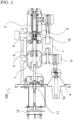
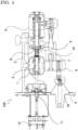
switch 100 will be described.FIG. 2 is a partial enlarged view of the fixed-side terminal 2 and shows the structure of themovable contact 8. As described above, themovable contact 8 includes theshaft rod 9 and thespring 10 provided therearound. As described below, at the time of closing, one end of themovable electrode rod 3 is engaged with themovable contact 8 and thus is electrically connected to theshaft rod 9. Theshaft rod 9 is positioned by astationary end 14 at the time of opening.FIG. 3 shows a closed state of theswitch 100.FIG. 4 shows shifting from the closed state inFIG. 3 to the opened state inFIG. 1 , i.e., an opening operation. - In
FIG. 3 , at the time of closing, themovable electrode rod 3 moves toward the fixed-side terminal 2 via themovable shaft 11 by theoperation mechanism portion 12. Then, themovable electrode rod 3 is inserted into the fixed-side terminal 2, to push thespring 10 and engage with themovable contact 8, so that the movable-side terminal 1 and the fixed-side terminal 2 become electrically conductive to each other. - In
FIG. 4 , when theswitch 100 starts an opening operation, themovable electrode rod 3 moves toward the movable-side terminal 1 side by theoperation mechanism portion 12, and theshaft rod 9 of themovable contact 8 moves toward the movable-side terminal 1 side while engaging with themovable electrode rod 3, so that thespring 10 composing themovable contact 8 is energized so as to extend. When themovable electrode rod 3 or theshaft rod 9 reaches a predetermined position, engagement of themovable contact 8 and themovable electrode rod 3 is released, so that thespring 10 is released. Themovable contact 8 is stored into the fixed-side terminal 2 and themovable electrode rod 3 is stored into the movable-side terminal 1, whereby the opening operation is completed, thus coming into the opened state inFIG. 1 . - During the opening operation to shift from the state in
FIG. 4 to the state inFIG. 1 , when thespring 10 is released, themovable contact 8 moves into the fixed-side terminal 2 and theshaft rod 9 comes into contact with thestationary end 14, so that an impact force occurs. The switch needs to have a structure for withstanding the impact force.FIG. 5 shows a comparative example of embodiment 1, and is different fromFIG. 1 in that the secondinsulation support portion 7 is not provided and the fixed-side terminal 2 is not supported from below. In the structure as shown inFIG. 5 , at the time of opening, themovable contact 8 is stored into the fixed-side terminal 2 and theshaft rod 9 comes into contact with thestationary end 14, so that an impact force occurs. At this time, a load acts on the fixed-side terminal 2 in the horizontal direction. Since the fixed-side terminal 2 is supported with a cantilever structure by the firstinsulation support portion 5, a load acts on the firstinsulation support portion 5 upward as shown by an arrow inFIG. 5 . In this structure, for improving the current interruption performance, it is conceivable that the load of thespring 10 is increased to increase the opening/closing speed. However, increase in the impact force depending on the stored energy of thespring 10 might cause deformation or breakage of the firstinsulation support portion 5. - In embodiment 1, as shown in
FIG. 1 ,FIG. 3 , andFIG. 4 , the upper part of the fixed-side terminal 2 is supported by the firstinsulation support portion 5, and the lower part of the fixed-side terminal 2 located at a symmetric position with respect to themovable shaft 11 is supported by the secondinsulation support portion 7. The firstinsulation support portion 5 and the secondinsulation support portion 7 support the fixed-side terminal 2 so as to be parallel and symmetric with respect to themovable shaft 11. That is, the firstinsulation support portion 5 and the secondinsulation support portion 7 are provided such that, inFIG. 1 , a distance L1 between themovable shaft 11 and the firstinsulation support portion 5, and a distance L2 between themovable shaft 11 and the secondinsulation support portion 7, are almost equal to each other. - In embodiment 1, the structure of the switch for one phase is shown in
FIG. 1 ,FIG. 3 , andFIG. 4 . However, in a switch for three phases, three of such devices are arranged in the horizontal direction. That is, the switch is configured such that three devices are arranged in the depth direction in the drawings. In this case, the firstinsulation support portions 5 and the second insulation support portions supporting the fixed-side terminals 2 are arranged on the upper and lower sides, whereby the distances between the devices for three phases can be reduced. - Desirably, the first
insulation support portion 5 and the secondinsulation support portion 7 are formed by using, for example, epoxy resin, etc., and are adjusted such that the elastic deformation amounts of the firstinsulation support portion 5 and the secondinsulation support portion 7 become equivalent to each other when an opening/closing impact occurs, thus forming such a structure that a load does not act unevenly on only one of the firstinsulation support portion 5 and the secondinsulation support portion 7. With this structure, propagation of an impact force to theflange 4 supporting theswitch 100 can be suppressed. Thus, without increasing the strength of theflange 4, it becomes possible to increase the opening/closing speed so as to improve the current interruption performance. - As described above, in the
switch 100 according to embodiment 1, the fixed-side terminal 2 is supported by the firstinsulation support portion 5 and the secondinsulation support portion 7 at symmetric positions with respect to themovable shaft 11, and the firstinsulation support portion 5 and the secondinsulation support portion 7 are parallel with themovable shaft 11 and each have an end fixed by theflange 4. Thus, an impact force in an opening/closing operation of theswitch 100 can be dispersed by the firstinsulation support portion 5 and the secondinsulation support portion 7, whereby it becomes possible to provide a switch having a stable current interruption function. - In addition, the fixed-
side terminal 2 is supported by the firstinsulation support portion 5 and the secondinsulation support portion 7 and thus a load is dispersed therebetween, whereby the mechanical strengths of the firstinsulation support portion 5, the secondinsulation support portion 7, and theoperation mechanism portion 12 can be designed to be lower than in conventional art. As a result, the switch can be downsized, thus leading to reduction in the installation space of the switch and cost reduction of the switch. - Hereinafter, a switch according to
embodiment 2 will be described with reference toFIG. 6 . -
FIG. 6 is a specific part sectional view showing the structure of the switch according toembodiment 2. InFIG. 6 , theswitch 100 is in an opened state. Difference fromFIG. 1 is that a lower part of the fixed-side terminal 2 is supported by a secondinsulation support portion 15 directly fixed to theflange 4. The other structures are the same as those in embodiment 1 and therefore description thereof is omitted. - In
FIG. 6 , the secondinsulation support portion 15 is directly fixed to theflange 4, and thesupport conductor 6 on the movable side is fixed to theflange 4 independently of the secondinsulation support portion 15. As in embodiment 1, the secondinsulation support portion 15 and the firstinsulation support portion 5 are arranged at symmetric positions with respect to themovable shaft 11 and in parallel with themovable shaft 11 such that the distance L1 between themovable shaft 11 and the firstinsulation support portion 5, and the distance L2 between themovable shaft 11 and the secondinsulation support portion 15, are almost equal to each other. In addition, the secondinsulation support portion 15 and the firstinsulation support portion 5 are adjusted such that their elastic deformation amounts become equivalent to each other. Thus, since the lower part of the fixed-side terminal 2 is directly supported by the secondinsulation support portion 15, thecoupling portion 13 need not be provided as in embodiment 1, so that the number of components can be decreased. The movable-side terminal 1 is supported by the firstinsulation support portion 5 and thesupport conductor 6 fixed to theflange 4. - As described above, according to
embodiment 2, the same effects as those in embodiment 1 are provided, and in addition, it is possible to obtain a switch having such a structure that the fixed-side terminal 2 is supported from two directions and loads acting on the firstinsulation support portion 5 and the secondinsulation support portion 15 are dispersed, with a decreased number of components. - The
above embodiments 1 and 2 have shown the examples in which the fixed-side terminal 2 is supported by the insulation support portions from the upper and lower parts as symmetric positions with respect to themovable shaft 11. However, as long as designing can be made such that a load at the time of opening/closing is equivalently dispersed between two support members supporting the fixed-side terminal 2, the support positions are not limited to the upper and lower parts. The support positions may be symmetric positions at an angle shifted from the vertical direction, or may be positions in the horizontal direction with respect to themovable shaft 11. - The
above embodiments 1 and 2 have shown the examples in which the fixed-side terminal 2 is supported by the insulation support portions from the upper and lower parts as symmetric positions with respect to themovable shaft 11. However, the number of the insulation support portions is not limited to two. The insulation support portions may be arranged at equal distances from themovable shaft 11 and at equiangular positions around themovable shaft 11 so that a load can be dispersed. - In a case of using the switch according to any of the
above embodiments 1 and 2 and the other embodiments for a gas-insulated switchgear, components other than the operation mechanism portion, e.g., the movable-side terminal, the fixed-side terminal, the insulation support portions, and the like are stored in a hermetic container in which SF6 gas, dry air, or the like is sealed, and an opening/closing operation is performed via the operation mechanism portion from the outside of the hermetic container. - Although the disclosure is described above in terms of various exemplary embodiments and implementations, it should be understood that the various features, aspects, and functionality described in one or more of the individual embodiments are not limited in their applicability to the particular embodiment with which they are described, but instead can be applied, alone or in various combinations to one or more of the embodiments of the disclosure.
- It is therefore understood that numerous modifications which have not been exemplified can be devised without departing from the scope of the present disclosure. For example, at least one of the constituent components may be modified, added, or eliminated. At least one of the constituent components mentioned in at least one of the preferred embodiments may be selected and combined with the constituent components mentioned in another preferred embodiment.
-
- 1 movable-side terminal
- 2 fixed-side terminal
- 3 movable electrode rod
- 4 flange
- 5 first insulation support portion
- 6 support conductor
- 7, 15 second insulation support portion
- 8 movable contact
- 9 shaft rod
- 10 spring
- 11 movable shaft
- 12 operation mechanism portion
- 13 coupling portion
- 14 stationary end
- 16 bushing
- 100 switch
- L1 distance between movable shaft and first insulation support portion
- L2 distance between movable shaft and second insulation support portion
Claims (7)
- A switch comprising:a fixed-side terminal having a movable contact; anda movable-side terminal which is provided so as to be opposed to the fixed-side terminal and includes a movable electrode rod which ensures electric conduction to the fixed-side terminal and is contactable therewith/separable therefrom, whereinthe movable-side terminal is fixed on a side opposite to a side where the movable-side terminal is opposed to the fixed-side terminal,the movable contact has a shaft rod movable coaxially with the movable electrode rod, and a spring biasing the shaft rod,at a time of closing between the fixed-side terminal and the movable-side terminal, an end of the movable electrode rod is engaged with the movable contact,at a time of opening between the fixed-side terminal and the movable-side terminal, in a state in which the movable electrode rod is engaged with the movable contact, the movable electrode rod moves toward the movable-side terminal, so that the spring is energized, and when the movable electrode rod reaches a predetermined position, the spring is released, so that the shaft rod moves toward the fixed-side terminal, thus separating the movable contact from the movable electrode rod, andthe fixed-side terminal is supported by a plurality of insulation support portions provided at symmetric positions with respect to an axis on which the movable electrode rod moves, an end of each insulation support portion being fixed.
- The switch according to claim 1, wherein
the plurality of insulation support portions are provided in parallel with and at equal distances from the axis on which the movable electrode rod moves. - The switch according to claim 1 or 2, wherein
the plurality of insulation support portions are made of resin and adjusted to be equivalent in elastic deformation amount. - The switch according to any one of claims 1 to 3, wherein
one of the plurality of insulation support portions supports both of the fixed-side terminal and the movable-side terminal. - The switch according to claim 4, wherein
one of the plurality of insulation support portions is provided at a position symmetric with the insulation support portion supporting both of the fixed-side terminal and the movable-side terminal, with respect to the axis on which the movable electrode rod moves. - The switch according to any one of claims 1 to 5, whereina number of the insulation support portions is two, andone of the insulation support portions supports an upper part of the fixed-side terminal, and another one supports a lower part of the fixed-side terminal.
- A gas-insulated switchgear comprising the switch according to any one of claims 1 to 6.
Applications Claiming Priority (1)
| Application Number | Priority Date | Filing Date | Title |
|---|---|---|---|
| PCT/JP2021/000292 WO2022149232A1 (en) | 2021-01-07 | 2021-01-07 | Switchgear and gas-insulated switchgear |
Publications (3)
| Publication Number | Publication Date |
|---|---|
| EP4277058A1 true EP4277058A1 (en) | 2023-11-15 |
| EP4277058A4 EP4277058A4 (en) | 2024-02-14 |
| EP4277058B1 EP4277058B1 (en) | 2025-02-26 |
Family
ID=81255847
Family Applications (1)
| Application Number | Title | Priority Date | Filing Date |
|---|---|---|---|
| EP21917459.6A Active EP4277058B1 (en) | 2021-01-07 | 2021-01-07 | Switchgear and gas-insulated switchgear |
Country Status (4)
| Country | Link |
|---|---|
| EP (1) | EP4277058B1 (en) |
| JP (1) | JP7046272B1 (en) |
| TW (1) | TWI798927B (en) |
| WO (1) | WO2022149232A1 (en) |
Family Cites Families (4)
| Publication number | Priority date | Publication date | Assignee | Title |
|---|---|---|---|---|
| US3348001A (en) * | 1965-07-26 | 1967-10-17 | Westinghouse Electric Corp | Electric distribution system |
| JPS6025792Y2 (en) * | 1978-09-07 | 1985-08-02 | 株式会社明電舎 | Disconnector for excitation current switching |
| JP5179278B2 (en) * | 2008-07-23 | 2013-04-10 | 三菱電機株式会社 | Switch |
| JP5980103B2 (en) * | 2012-11-21 | 2016-08-31 | 三菱電機株式会社 | Gas insulated switchgear |
-
2021
- 2021-01-07 JP JP2021522569A patent/JP7046272B1/en active Active
- 2021-01-07 WO PCT/JP2021/000292 patent/WO2022149232A1/en not_active Ceased
- 2021-01-07 EP EP21917459.6A patent/EP4277058B1/en active Active
- 2021-11-11 TW TW110141980A patent/TWI798927B/en active
Also Published As
| Publication number | Publication date |
|---|---|
| EP4277058B1 (en) | 2025-02-26 |
| EP4277058A4 (en) | 2024-02-14 |
| JP7046272B1 (en) | 2022-04-01 |
| TWI798927B (en) | 2023-04-11 |
| WO2022149232A1 (en) | 2022-07-14 |
| TW202228174A (en) | 2022-07-16 |
| JPWO2022149232A1 (en) | 2022-07-14 |
Similar Documents
| Publication | Publication Date | Title |
|---|---|---|
| EP1826791A2 (en) | Three-position vacuum interrupter disconnect switch providing current interruption, disconnection and grounding | |
| US9082563B2 (en) | Power breaker | |
| EP2020668A2 (en) | Vacuum insulated switch and vacuum insulated switchgear | |
| KR20010024332A (en) | Switch gear | |
| JP2000268685A (en) | Switchgear | |
| KR102850154B1 (en) | A medium voltage switching apparatus | |
| EP4276872B1 (en) | A medium voltage switching apparatus | |
| EP4277058B1 (en) | Switchgear and gas-insulated switchgear | |
| KR102385436B1 (en) | Vacuum interrupter and vacuum circuit breaker having the same | |
| US12387890B2 (en) | Medium voltage switching apparatus | |
| EP4276869A1 (en) | A medium voltage switching apparatus | |
| CN101248503A (en) | Contact devices with limiting elements limiting the deflection of movable contacts | |
| US4736079A (en) | Puffer type electrical circuit breaker having a high dielectric withstand | |
| EP4459653B1 (en) | A switching apparatus for electrical systems | |
| JP4470228B2 (en) | Vacuum switch | |
| SU1089659A1 (en) | Vacuum circuit breaker | |
| EP4276871B1 (en) | A method for assembling a switching apparatus for medium voltage electric systems and a mounting assembly for a medium voltage switching apparatus | |
| US20250372324A1 (en) | Medium voltage switching apparatus | |
| EP4641601A1 (en) | A switching apparatus for electrical systems | |
| EP4435815A1 (en) | A switching apparatus for medium voltage electrical systems | |
| JP4945211B2 (en) | Three-phase collective earthing switch | |
| JP2016163499A (en) | Switchgear | |
| EP4411773A1 (en) | Ring-shaped coil spring of switchgear and switchgear using same | |
| CN118471712A (en) | Low-voltage switch pole | |
| JP2019096447A (en) | Solid insulated switchgear |
Legal Events
| Date | Code | Title | Description |
|---|---|---|---|
| STAA | Information on the status of an ep patent application or granted ep patent |
Free format text: STATUS: THE INTERNATIONAL PUBLICATION HAS BEEN MADE |
|
| PUAI | Public reference made under article 153(3) epc to a published international application that has entered the european phase |
Free format text: ORIGINAL CODE: 0009012 |
|
| STAA | Information on the status of an ep patent application or granted ep patent |
Free format text: STATUS: REQUEST FOR EXAMINATION WAS MADE |
|
| 17P | Request for examination filed |
Effective date: 20230424 |
|
| AK | Designated contracting states |
Kind code of ref document: A1 Designated state(s): AL AT BE BG CH CY CZ DE DK EE ES FI FR GB GR HR HU IE IS IT LI LT LU LV MC MK MT NL NO PL PT RO RS SE SI SK SM TR |
|
| REG | Reference to a national code |
Ref country code: DE Ref legal event code: R079 Free format text: PREVIOUS MAIN CLASS: H02B0013035000 Ipc: H01H0031020000 Ref country code: DE Ref legal event code: R079 Ref document number: 602021026944 Country of ref document: DE Free format text: PREVIOUS MAIN CLASS: H02B0013035000 Ipc: H01H0031020000 |
|
| A4 | Supplementary search report drawn up and despatched |
Effective date: 20240116 |
|
| RIC1 | Information provided on ipc code assigned before grant |
Ipc: H01H 33/40 20060101ALI20240111BHEP Ipc: H01H 31/32 20060101ALI20240111BHEP Ipc: H02B 13/035 20060101ALI20240111BHEP Ipc: H01H 31/02 20060101AFI20240111BHEP |
|
| DAV | Request for validation of the european patent (deleted) | ||
| DAX | Request for extension of the european patent (deleted) | ||
| GRAP | Despatch of communication of intention to grant a patent |
Free format text: ORIGINAL CODE: EPIDOSNIGR1 |
|
| STAA | Information on the status of an ep patent application or granted ep patent |
Free format text: STATUS: GRANT OF PATENT IS INTENDED |
|
| RIC1 | Information provided on ipc code assigned before grant |
Ipc: H01H 33/40 20060101ALI20240911BHEP Ipc: H01H 31/32 20060101ALI20240911BHEP Ipc: H02B 13/035 20060101ALI20240911BHEP Ipc: H01H 31/02 20060101AFI20240911BHEP |
|
| INTG | Intention to grant announced |
Effective date: 20240920 |
|
| RIN1 | Information on inventor provided before grant (corrected) |
Inventor name: YOSHIOKA, YOSHIKI Inventor name: ONISHI, KENJI Inventor name: MIYATAKE, HIDEKI Inventor name: KAGAWA, KOICHI Inventor name: MATSUNAGA, TOSHIHIRO Inventor name: YOSHIDA, TADAHIRO Inventor name: MORI, TAKAHIRO |
|
| GRAS | Grant fee paid |
Free format text: ORIGINAL CODE: EPIDOSNIGR3 |
|
| GRAA | (expected) grant |
Free format text: ORIGINAL CODE: 0009210 |
|
| STAA | Information on the status of an ep patent application or granted ep patent |
Free format text: STATUS: THE PATENT HAS BEEN GRANTED |
|
| AK | Designated contracting states |
Kind code of ref document: B1 Designated state(s): AL AT BE BG CH CY CZ DE DK EE ES FI FR GB GR HR HU IE IS IT LI LT LU LV MC MK MT NL NO PL PT RO RS SE SI SK SM TR |
|
| REG | Reference to a national code |
Ref country code: GB Ref legal event code: FG4D |
|
| REG | Reference to a national code |
Ref country code: CH Ref legal event code: EP |
|
| REG | Reference to a national code |
Ref country code: DE Ref legal event code: R096 Ref document number: 602021026944 Country of ref document: DE |
|
| REG | Reference to a national code |
Ref country code: IE Ref legal event code: FG4D |
|
| REG | Reference to a national code |
Ref country code: NL Ref legal event code: MP Effective date: 20250226 |
|
| PG25 | Lapsed in a contracting state [announced via postgrant information from national office to epo] |
Ref country code: RS Free format text: LAPSE BECAUSE OF FAILURE TO SUBMIT A TRANSLATION OF THE DESCRIPTION OR TO PAY THE FEE WITHIN THE PRESCRIBED TIME-LIMIT Effective date: 20250526 |
|
| PG25 | Lapsed in a contracting state [announced via postgrant information from national office to epo] |
Ref country code: FI Free format text: LAPSE BECAUSE OF FAILURE TO SUBMIT A TRANSLATION OF THE DESCRIPTION OR TO PAY THE FEE WITHIN THE PRESCRIBED TIME-LIMIT Effective date: 20250226 |
|
| PG25 | Lapsed in a contracting state [announced via postgrant information from national office to epo] |
Ref country code: PL Free format text: LAPSE BECAUSE OF FAILURE TO SUBMIT A TRANSLATION OF THE DESCRIPTION OR TO PAY THE FEE WITHIN THE PRESCRIBED TIME-LIMIT Effective date: 20250226 |
|
| PG25 | Lapsed in a contracting state [announced via postgrant information from national office to epo] |
Ref country code: ES Free format text: LAPSE BECAUSE OF FAILURE TO SUBMIT A TRANSLATION OF THE DESCRIPTION OR TO PAY THE FEE WITHIN THE PRESCRIBED TIME-LIMIT Effective date: 20250226 |
|
| REG | Reference to a national code |
Ref country code: LT Ref legal event code: MG9D |
|
| PG25 | Lapsed in a contracting state [announced via postgrant information from national office to epo] |
Ref country code: IS Free format text: LAPSE BECAUSE OF FAILURE TO SUBMIT A TRANSLATION OF THE DESCRIPTION OR TO PAY THE FEE WITHIN THE PRESCRIBED TIME-LIMIT Effective date: 20250626 Ref country code: NO Free format text: LAPSE BECAUSE OF FAILURE TO SUBMIT A TRANSLATION OF THE DESCRIPTION OR TO PAY THE FEE WITHIN THE PRESCRIBED TIME-LIMIT Effective date: 20250526 |
|
| PG25 | Lapsed in a contracting state [announced via postgrant information from national office to epo] |
Ref country code: NL Free format text: LAPSE BECAUSE OF FAILURE TO SUBMIT A TRANSLATION OF THE DESCRIPTION OR TO PAY THE FEE WITHIN THE PRESCRIBED TIME-LIMIT Effective date: 20250226 |
|
| PG25 | Lapsed in a contracting state [announced via postgrant information from national office to epo] |
Ref country code: HR Free format text: LAPSE BECAUSE OF FAILURE TO SUBMIT A TRANSLATION OF THE DESCRIPTION OR TO PAY THE FEE WITHIN THE PRESCRIBED TIME-LIMIT Effective date: 20250226 |
|
| PG25 | Lapsed in a contracting state [announced via postgrant information from national office to epo] |
Ref country code: PT Free format text: LAPSE BECAUSE OF FAILURE TO SUBMIT A TRANSLATION OF THE DESCRIPTION OR TO PAY THE FEE WITHIN THE PRESCRIBED TIME-LIMIT Effective date: 20250626 Ref country code: LV Free format text: LAPSE BECAUSE OF FAILURE TO SUBMIT A TRANSLATION OF THE DESCRIPTION OR TO PAY THE FEE WITHIN THE PRESCRIBED TIME-LIMIT Effective date: 20250226 |
|
| PG25 | Lapsed in a contracting state [announced via postgrant information from national office to epo] |
Ref country code: GR Free format text: LAPSE BECAUSE OF FAILURE TO SUBMIT A TRANSLATION OF THE DESCRIPTION OR TO PAY THE FEE WITHIN THE PRESCRIBED TIME-LIMIT Effective date: 20250527 Ref country code: BG Free format text: LAPSE BECAUSE OF FAILURE TO SUBMIT A TRANSLATION OF THE DESCRIPTION OR TO PAY THE FEE WITHIN THE PRESCRIBED TIME-LIMIT Effective date: 20250226 |
|
| REG | Reference to a national code |
Ref country code: AT Ref legal event code: MK05 Ref document number: 1771533 Country of ref document: AT Kind code of ref document: T Effective date: 20250226 |
|
| PG25 | Lapsed in a contracting state [announced via postgrant information from national office to epo] |
Ref country code: SE Free format text: LAPSE BECAUSE OF FAILURE TO SUBMIT A TRANSLATION OF THE DESCRIPTION OR TO PAY THE FEE WITHIN THE PRESCRIBED TIME-LIMIT Effective date: 20250226 |
|
| P01 | Opt-out of the competence of the unified patent court (upc) registered |
Free format text: CASE NUMBER: UPC_APP_4952_4277058/2025 Effective date: 20250827 |
|
| PG25 | Lapsed in a contracting state [announced via postgrant information from national office to epo] |
Ref country code: SM Free format text: LAPSE BECAUSE OF FAILURE TO SUBMIT A TRANSLATION OF THE DESCRIPTION OR TO PAY THE FEE WITHIN THE PRESCRIBED TIME-LIMIT Effective date: 20250226 |
|
| PG25 | Lapsed in a contracting state [announced via postgrant information from national office to epo] |
Ref country code: DK Free format text: LAPSE BECAUSE OF FAILURE TO SUBMIT A TRANSLATION OF THE DESCRIPTION OR TO PAY THE FEE WITHIN THE PRESCRIBED TIME-LIMIT Effective date: 20250226 |
|
| PG25 | Lapsed in a contracting state [announced via postgrant information from national office to epo] |
Ref country code: AT Free format text: LAPSE BECAUSE OF FAILURE TO SUBMIT A TRANSLATION OF THE DESCRIPTION OR TO PAY THE FEE WITHIN THE PRESCRIBED TIME-LIMIT Effective date: 20250226 |
|
| PG25 | Lapsed in a contracting state [announced via postgrant information from national office to epo] |
Ref country code: EE Free format text: LAPSE BECAUSE OF FAILURE TO SUBMIT A TRANSLATION OF THE DESCRIPTION OR TO PAY THE FEE WITHIN THE PRESCRIBED TIME-LIMIT Effective date: 20250226 Ref country code: CZ Free format text: LAPSE BECAUSE OF FAILURE TO SUBMIT A TRANSLATION OF THE DESCRIPTION OR TO PAY THE FEE WITHIN THE PRESCRIBED TIME-LIMIT Effective date: 20250226 |
|
| PG25 | Lapsed in a contracting state [announced via postgrant information from national office to epo] |
Ref country code: RO Free format text: LAPSE BECAUSE OF FAILURE TO SUBMIT A TRANSLATION OF THE DESCRIPTION OR TO PAY THE FEE WITHIN THE PRESCRIBED TIME-LIMIT Effective date: 20250226 |
|
| PG25 | Lapsed in a contracting state [announced via postgrant information from national office to epo] |
Ref country code: SK Free format text: LAPSE BECAUSE OF FAILURE TO SUBMIT A TRANSLATION OF THE DESCRIPTION OR TO PAY THE FEE WITHIN THE PRESCRIBED TIME-LIMIT Effective date: 20250226 |
|
| REG | Reference to a national code |
Ref country code: DE Ref legal event code: R097 Ref document number: 602021026944 Country of ref document: DE |
|
| PLBE | No opposition filed within time limit |
Free format text: ORIGINAL CODE: 0009261 |
|
| STAA | Information on the status of an ep patent application or granted ep patent |
Free format text: STATUS: NO OPPOSITION FILED WITHIN TIME LIMIT |
|
| PGFP | Annual fee paid to national office [announced via postgrant information from national office to epo] |
Ref country code: FR Payment date: 20251128 Year of fee payment: 6 |
|
| 26N | No opposition filed |
Effective date: 20251127 |
|
| PGFP | Annual fee paid to national office [announced via postgrant information from national office to epo] |
Ref country code: DE Payment date: 20251203 Year of fee payment: 6 |
|
| PGFP | Annual fee paid to national office [announced via postgrant information from national office to epo] |
Ref country code: IT Payment date: 20251219 Year of fee payment: 6 |