EP4277057A1 - Gas-insulated switching device - Google Patents
Gas-insulated switching device Download PDFInfo
- Publication number
- EP4277057A1 EP4277057A1 EP21917458.8A EP21917458A EP4277057A1 EP 4277057 A1 EP4277057 A1 EP 4277057A1 EP 21917458 A EP21917458 A EP 21917458A EP 4277057 A1 EP4277057 A1 EP 4277057A1
- Authority
- EP
- European Patent Office
- Prior art keywords
- electrode
- movable electrode
- movable
- fixed electrode
- contact
- Prior art date
- Legal status (The legal status is an assumption and is not a legal conclusion. Google has not performed a legal analysis and makes no representation as to the accuracy of the status listed.)
- Granted
Links
Images




Classifications
-
- H—ELECTRICITY
- H01—ELECTRIC ELEMENTS
- H01H—ELECTRIC SWITCHES; RELAYS; SELECTORS; EMERGENCY PROTECTIVE DEVICES
- H01H31/00—Air-break switches for high tension without arc-extinguishing or arc-preventing means
- H01H31/26—Air-break switches for high tension without arc-extinguishing or arc-preventing means with movable contact that remains electrically connected to one line in open position of switch
- H01H31/32—Air-break switches for high tension without arc-extinguishing or arc-preventing means with movable contact that remains electrically connected to one line in open position of switch with rectilinearly-movable contact
-
- H—ELECTRICITY
- H01—ELECTRIC ELEMENTS
- H01H—ELECTRIC SWITCHES; RELAYS; SELECTORS; EMERGENCY PROTECTIVE DEVICES
- H01H1/00—Contacts
- H01H1/50—Means for increasing contact pressure, preventing vibration of contacts, holding contacts together after engagement, or biasing contacts to the open position
- H01H1/52—Contacts adapted to act as latches
-
- H—ELECTRICITY
- H01—ELECTRIC ELEMENTS
- H01H—ELECTRIC SWITCHES; RELAYS; SELECTORS; EMERGENCY PROTECTIVE DEVICES
- H01H1/00—Contacts
- H01H1/12—Contacts characterised by the manner in which co-operating contacts engage
- H01H1/36—Contacts characterised by the manner in which co-operating contacts engage by sliding
- H01H1/38—Plug-and-socket contacts
-
- H—ELECTRICITY
- H01—ELECTRIC ELEMENTS
- H01H—ELECTRIC SWITCHES; RELAYS; SELECTORS; EMERGENCY PROTECTIVE DEVICES
- H01H33/00—High-tension or heavy-current switches with arc-extinguishing or arc-preventing means
- H01H33/02—Details
- H01H33/04—Means for extinguishing or preventing arc between current-carrying parts
- H01H33/12—Auxiliary contacts on to which the arc is transferred from the main contacts
- H01H33/121—Load break switches
Definitions
- the present disclosure relates to a gas insulated switchgear.
- a gas insulated switchgear includes a switch for interrupting current.
- the switch includes a movable-side terminal having a movable electrode, a fixed-side terminal provided so as to be opposed to the movable-side terminal, and a driving portion for linearly driving the movable electrode toward the fixed-side terminal.
- the fixed-side terminal has a fixed electrode, a latch portion for engaging the fixed electrode with the movable electrode, and an opening mechanism for separating the fixed electrode from the movable electrode.
- the opening mechanism has an opening spring for driving the fixed electrode in a direction to separate from the movable electrode.
- the driving portion drives the movable electrode in a direction to approach the fixed electrode, so as to engage the movable electrode and the fixed electrode with each other.
- the driving portion drives the movable electrode in a direction away from the fixed electrode.
- the fixed electrode is pulled together with the movable electrode, whereby the opening spring of the opening mechanism is contracted.
- engagement of the latch portion is released by a restoring force of the opening spring.
- the fixed electrode is separated from the movable electrode, whereby the switch is opened.
- a conventional latch portion of a switch has a plate spring structure of which one end is fixed and another end has a claw portion (see, for example, Patent Document 1).
- Patent Document 1 Japanese Laid-Open Patent Publication No. 2010-27479
- the claw portion needs to have both a function of keeping engagement between the movable electrode and the fixed electrode against a spring load of the opening spring, and a function of releasing the engagement in accordance with the position of the fixed electrode. Therefore, because of axial misalignment between the movable electrode and the fixed electrode, change in a frictional force at the claw portion and a part engaged with the claw portion, and the like, the position where the fixed electrode is separated from the movable electrode is not stabilized, and since an engagement retaining force is weak, an opening spring having a great spring load cannot be applied, and thus the interruption speed cannot be increased.
- the present disclosure has been made to solve the above problem, and an object of the present disclosure is to provide a gas insulated switchgear having a switch that enables adjustment of the interruption speed while stabilizing the position where the fixed electrode is separated from the movable electrode.
- a gas insulated switchgear includes: a movable electrode; a fixed electrode provided on a same axis as the movable electrode; a driving portion which linearly drives the movable electrode in a direction of the axis so that the movable electrode contacts with/separates from the fixed electrode; and an opening mechanism which separates the fixed electrode from the movable electrode.
- the movable electrode has a taper portion having a recessed surface toward the axis, at a part to contact with the fixed electrode, and has a protrusion protruding toward the axis, at an outer circumferential part of the taper portion.
- the fixed electrode includes a latch portion composed of a claw having an engagement portion to be engaged with the protrusion and a slope portion to contact with the taper portion, and a contact-pressure spring applying a restoring force to the claw in a direction crossing the axis.
- the fixed electrode includes the latch portion composed of the claw having the engagement portion to be engaged with the protrusion and the slope portion to contact with the taper portion, and the contact-pressure spring applying the restoring force to the claw in the direction crossing the axis.
- FIG. 1 is a sectional view of a switch of a gas insulated switchgear according to embodiment 1.
- a switch 1 of the gas insulated switchgear shown in FIG. 1 is in an opened state.
- the switch 1 includes a flange 2, a fixed-side terminal 4 fixed to an insulation holder 3, and a movable-side terminal 5.
- a cylindrical movable electrode rod 6 having a threaded inner circumferential surface and a columnar movable-side shaft rod 7 for linearly driving the movable electrode rod 6, are provided inside the movable-side terminal 5.
- the movable electrode rod 6 and the movable-side shaft rod 7 are provided on the same axis, and the movable electrode rod 6 and the movable-side shaft rod 7 compose a movable electrode 8.
- the outer circumferential surface of the movable-side shaft rod 7 is threaded for linearly driving the movable electrode rod 6.
- An insulation rod 9 is connected to one end of the movable-side shaft rod 7.
- the insulation rod 9 is connected to a driving portion 10.
- a conductive spring component (not shown) is provided between the movable-side terminal 5 and the movable electrode rod 6.
- the longitudinal direction of the movable electrode rod 6 and the movable-side shaft rod 7 provided on the same axis is referred to as an axial direction.
- the fixed-side terminal 4 includes a base conductor 11, a cylindrical conductor 12 connected to the base conductor, a piston 13 provided inside the cylindrical conductor 12, a cylinder 14 provided between the cylindrical conductor 12 and the piston 13, a fixed electrode 15 connected to an end of the cylinder 14, and an opening spring 16 provided around the outer circumference of the cylinder 14.
- the piston 13, the cylinder 14, and the opening spring 16 compose an opening mechanism.
- the fixed electrode 15 is provided on the same axis as the movable electrode.
- An electric field relaxing shield 17 is provided at an outer circumferential part of the fixed electrode 15. The electric field relaxing shield 17 is drawn out toward the movable-side terminal 5 together with the fixed electrode 15 when the fixed electrode 15 is pulled toward the movable-side terminal 5.
- An electrode contact-pressure spring 18 is provided at an outer circumferential part of the fixed electrode 15, so as to keep contact between the movable electrode rod 6 and the fixed electrode 15 when the movable electrode rod 6 and the fixed electrode 15 are conductively in contact with each other.
- FIG. 2 is a sectional view of the fixed electrode 15.
- FIG. 3 is a plan view of the fixed electrode 15 as seen from A side in FIG. 2
- FIG. 4 is a plan view of the fixed electrode 15 as seen from B side in FIG. 2 .
- the fixed electrode 15 includes a connection rod 19 connected to the cylinder 14, a fixed-side shaft rod 20, two claws 21 radially formed in directions crossing the axial direction of the fixed-side shaft rod 20, a stopper 22 restricting movement of the claws 21 in the axial direction and the radial direction, and a contact-pressure spring 23 pushing out the claws 21 in the outer circumferential direction.
- the two claws 21 are provided at positions opposed to each other with respect to the axis.
- the two claws 21 and the contact-pressure spring 23 compose a latch portion 24.
- the claws 21 are pushed out in the outer circumferential direction by the restoring force of the contact-pressure spring 23.
- the outer periphery of each claw 21 has a circular shape, an elliptic shape, a quadrangular shape, or a shape formed by combination thereof.
- the claw 21 has an engagement portion 21a to be engaged with a protrusion formed at the movable electrode rod as described later, and a slope portion 21b to contact with a taper portion formed at the movable-side shaft rod. As shown in FIG. 2 , the engagement portions 21a of the claws 21 have a shape protruding to the outer circumferential side.
- the slope portions 21b of the claws 21 have such a shape that the distal end tapers toward the movable electrode side.
- the clearance between the fixed-side shaft rod 20 and the claws 21 in the axial direction, i.e., the horizontal direction in FIG. 2 is set to be small so as to suppress wobbling of the latch portion 24.
- the driving portion 10 rotates the insulation rod 9, for example, clockwise.
- the movable-side shaft rod 7 rotates about the axis.
- the movable electrode rod 6 is linearly driven rightward in FIG. 1 through meshing between the thread on the outer circumferential surface of the movable-side shaft rod 7 and the thread on the inner circumferential surface of the movable electrode rod 6.
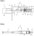
- FIG. 5 is a sectional view of the switch of the gas insulated switchgear according to the present embodiment, in a closed state.
- the distal end of the movable electrode rod 6 contacts with the fixed electrode 15.
- FIG. 6 is an enlarged sectional view of a specific part of the switch 1 in a closed state in the present embodiment.
- a taper portion 7a having a recessed surface toward the axis is formed at the distal end of the movable-side shaft rod 7.
- a protrusion 6a protruding toward the axis is formed on the inner circumferential surface at the distal end of the movable electrode rod 6.
- the engagement portion 21a of each claw 21 is engaged with the protrusion 6a, so that the fixed electrode 15 and the movable electrode 8 are electrically connected to each other.
- the driving portion 10 rotates the insulation rod 9 counterclockwise.
- the movable-side shaft rod 7 rotates about the axis.
- the movable electrode rod 6 is linearly driven leftward in FIG. 5 through meshing between the thread on the outer circumferential surface of the movable-side shaft rod 7 and the thread on the inner circumferential surface of the movable electrode rod 6.
- FIG. 7 is a sectional view of the switch of the gas insulated switchgear according to the present embodiment, just before the switch is opened.
- the fixed electrode 15 pulled by the movable electrode rod 6 linearly driven leftward enters the inside of the movable-side terminal 5, and the distal end of the fixed electrode 15 contacts with the distal end of the movable-side shaft rod 7.
- FIG. 8 is an enlarged sectional view of a specific part where the movable-side shaft rod 7 and the fixed electrode 15 contact with each other. As shown in FIG.
- FIG. 9 is a sectional view of the switch of the gas insulated switchgear according to the present embodiment, just before the engagement between the engagement portion 21a of each claw 21 and the protrusion 6a of the movable electrode rod 6 is released.
- the slope portion 21b of each claw 21 is compressed along the taper portion 7a, the engagement portion 21a moves toward the inner circumferential side, so that the engagement between the engagement portion 21a and the protrusion 6a of the movable electrode rod 6 is released.
- the fixed electrode 15 moves rightward by the restoring force of the opening spring 16 that has been compressed, so that the fixed electrode 15 is separated from the movable electrode 8.
- electric connection between the fixed electrode 15 and the movable electrode 8 is disconnected, so that the switch 1 comes into the opened state shown in FIG. 1 .
- the latch portion of the switch includes the claw having the engagement portion to be engaged with the protrusion of the movable electrode and the slope portion to contact with the taper portion of the movable electrode rod, and the contact-pressure spring applying the restoring force to the claw in the direction crossing the axis.
- the force for keeping engagement between the fixed electrode and the movable electrode against the spring load of the opening spring can be adjusted by, for example, the contact angle and the contact area between the engagement portion of the claw and the protrusion of the movable electrode rod.
- the position of the fixed electrode when the engagement is released can be adjusted by, for example, the contact angle and the contact area between the slope portion of the claw and the taper portion of the movable-side shaft rod, and the spring load of the contact-pressure spring.
- the part bearing the function of keeping engagement between the fixed electrode and the movable electrode against the spring load of the opening spring and the part bearing the function of releasing the engagement in accordance with the position of the fixed electrode can be separated from each other, and therefore the respective functions can be adjusted without influencing each other function. Further, since the clearance between the fixed-side shaft rod 20 and the claw 21 in the axial direction is set to be small, it becomes possible to increase the load of the opening spring. Thus, the opening speed can be increased.
- the latch portion of the switch includes the claw having the engagement portion to be engaged with the protrusion of the movable electrode and the slope portion to contact with the taper portion of the movable electrode rod, and the contact-pressure spring applying the restoring force to the claw in the direction crossing the axis.
- the latch portion has two claws.
- the latch portion may have three or more claws.
- FIG. 10 is a sectional view of a fixed electrode of a switch of a gas insulated switchgear according to embodiment 2.
- the structure of the switch in the present embodiment is the same as the structure of the switch in embodiment 1.
- the fixed electrode 15 according to the present embodiment includes two contact-pressure springs 23 pushing out the two claws 21 in the outer circumferential direction.
- the two contact-pressure springs 23 are respectively provided between the fixed-side shaft rod 20 and the two claws 21.
- the function of keeping engagement between the fixed electrode and the movable electrode against the spring load of the opening spring can be borne by the engagement portion, and the function of releasing the engagement in accordance with the position of the fixed electrode can be borne by the slope portion.
- the fixed electrode since the fixed electrode includes two contact-pressure springs 23 pushing out the two claws 21 in the outer circumferential direction, the two claws 21 can be operated independently of each other. As a result, it is possible to suppress variations in the contact pressures against the respective claws due to axial misalignment between the movable electrode and the fixed electrode, driving vibration, or the like.
Landscapes
- Driving Mechanisms And Operating Circuits Of Arc-Extinguishing High-Tension Switches (AREA)
- Gas-Insulated Switchgears (AREA)
- Circuit Breakers (AREA)
Abstract
Description
- The present disclosure relates to a gas insulated switchgear.
- A gas insulated switchgear includes a switch for interrupting current. The switch includes a movable-side terminal having a movable electrode, a fixed-side terminal provided so as to be opposed to the movable-side terminal, and a driving portion for linearly driving the movable electrode toward the fixed-side terminal. The fixed-side terminal has a fixed electrode, a latch portion for engaging the fixed electrode with the movable electrode, and an opening mechanism for separating the fixed electrode from the movable electrode. The opening mechanism has an opening spring for driving the fixed electrode in a direction to separate from the movable electrode.
- At the time of closing the switch, the driving portion drives the movable electrode in a direction to approach the fixed electrode, so as to engage the movable electrode and the fixed electrode with each other. At the time of opening the switch, the driving portion drives the movable electrode in a direction away from the fixed electrode. At this time, the fixed electrode is pulled together with the movable electrode, whereby the opening spring of the opening mechanism is contracted. When the fixed electrode is pulled to a predetermined position, engagement of the latch portion is released by a restoring force of the opening spring. Thus, the fixed electrode is separated from the movable electrode, whereby the switch is opened.
- A conventional latch portion of a switch has a plate spring structure of which one end is fixed and another end has a claw portion (see, for example, Patent Document 1).
- Patent Document 1:
Japanese Laid-Open Patent Publication No. 2010-27479 - In the conventional latch portion, the claw portion needs to have both a function of keeping engagement between the movable electrode and the fixed electrode against a spring load of the opening spring, and a function of releasing the engagement in accordance with the position of the fixed electrode. Therefore, because of axial misalignment between the movable electrode and the fixed electrode, change in a frictional force at the claw portion and a part engaged with the claw portion, and the like, the position where the fixed electrode is separated from the movable electrode is not stabilized, and since an engagement retaining force is weak, an opening spring having a great spring load cannot be applied, and thus the interruption speed cannot be increased.
- The present disclosure has been made to solve the above problem, and an object of the present disclosure is to provide a gas insulated switchgear having a switch that enables adjustment of the interruption speed while stabilizing the position where the fixed electrode is separated from the movable electrode.
- A gas insulated switchgear according to the present disclosure includes: a movable electrode; a fixed electrode provided on a same axis as the movable electrode; a driving portion which linearly drives the movable electrode in a direction of the axis so that the movable electrode contacts with/separates from the fixed electrode; and an opening mechanism which separates the fixed electrode from the movable electrode. The movable electrode has a taper portion having a recessed surface toward the axis, at a part to contact with the fixed electrode, and has a protrusion protruding toward the axis, at an outer circumferential part of the taper portion. The fixed electrode includes a latch portion composed of a claw having an engagement portion to be engaged with the protrusion and a slope portion to contact with the taper portion, and a contact-pressure spring applying a restoring force to the claw in a direction crossing the axis.
- In the gas insulated switchgear according to the present disclosure, the fixed electrode includes the latch portion composed of the claw having the engagement portion to be engaged with the protrusion and the slope portion to contact with the taper portion, and the contact-pressure spring applying the restoring force to the claw in the direction crossing the axis. Thus, it is possible to adjust the interruption speed while stabilizing the position where the fixed electrode is separated from the movable electrode.
-
- [
FIG. 1] FIG. 1 is a sectional view of a gas insulated switchgear according toembodiment 1. - [
FIG. 2] FIG. 2 is a sectional view of a fixed electrode according toembodiment 1. - [
FIG. 3] FIG. 3 is a plan view of the fixed electrode according toembodiment 1. - [
FIG. 4] FIG. 4 is a plan view of the fixed electrode according toembodiment 1. - [
FIG. 5] FIG. 5 is a sectional view of the gas insulated switchgear according toembodiment 1. - [
FIG. 6] FIG. 6 is an enlarged sectional view of a switch according toembodiment 1. - [
FIG. 7] FIG. 7 is a sectional view of the gas insulated switchgear according toembodiment 1. - [
FIG. 8] FIG. 8 is an enlarged sectional view of the switch according toembodiment 1. - [
FIG. 9] FIG. 9 is an enlarged sectional view of the switch according toembodiment 1. - [
FIG. 10] FIG. 10 is a sectional view of a fixed electrode according toembodiment 2. - Hereinafter, a gas insulated switchgear according to embodiments for carrying out the present disclosure will be described in detail with reference to the drawings. In the drawings, the same reference characters denote the same or corresponding parts.
-
FIG. 1 is a sectional view of a switch of a gas insulated switchgear according toembodiment 1. Aswitch 1 of the gas insulated switchgear shown inFIG. 1 is in an opened state. Theswitch 1 includes aflange 2, a fixed-side terminal 4 fixed to aninsulation holder 3, and a movable-side terminal 5. A cylindricalmovable electrode rod 6 having a threaded inner circumferential surface and a columnar movable-side shaft rod 7 for linearly driving themovable electrode rod 6, are provided inside the movable-side terminal 5. Themovable electrode rod 6 and the movable-side shaft rod 7 are provided on the same axis, and themovable electrode rod 6 and the movable-side shaft rod 7 compose amovable electrode 8. The outer circumferential surface of the movable-side shaft rod 7 is threaded for linearly driving themovable electrode rod 6. Aninsulation rod 9 is connected to one end of the movable-side shaft rod 7. Theinsulation rod 9 is connected to adriving portion 10. A conductive spring component (not shown) is provided between the movable-side terminal 5 and themovable electrode rod 6. Hereinafter, the longitudinal direction of themovable electrode rod 6 and the movable-side shaft rod 7 provided on the same axis is referred to as an axial direction. - The fixed-
side terminal 4 includes abase conductor 11, acylindrical conductor 12 connected to the base conductor, apiston 13 provided inside thecylindrical conductor 12, acylinder 14 provided between thecylindrical conductor 12 and thepiston 13, afixed electrode 15 connected to an end of thecylinder 14, and anopening spring 16 provided around the outer circumference of thecylinder 14. Thepiston 13, thecylinder 14, and theopening spring 16 compose an opening mechanism. Thefixed electrode 15 is provided on the same axis as the movable electrode. An electricfield relaxing shield 17 is provided at an outer circumferential part of the fixedelectrode 15. The electricfield relaxing shield 17 is drawn out toward the movable-side terminal 5 together with thefixed electrode 15 when thefixed electrode 15 is pulled toward the movable-side terminal 5. An electrode contact-pressure spring 18 is provided at an outer circumferential part of thefixed electrode 15, so as to keep contact between themovable electrode rod 6 and thefixed electrode 15 when themovable electrode rod 6 and thefixed electrode 15 are conductively in contact with each other. -
FIG. 2 is a sectional view of thefixed electrode 15.FIG. 3 is a plan view of thefixed electrode 15 as seen from A side inFIG. 2 , andFIG. 4 is a plan view of thefixed electrode 15 as seen from B side inFIG. 2 . Thefixed electrode 15 includes aconnection rod 19 connected to thecylinder 14, a fixed-side shaft rod 20, twoclaws 21 radially formed in directions crossing the axial direction of the fixed-side shaft rod 20, astopper 22 restricting movement of theclaws 21 in the axial direction and the radial direction, and a contact-pressure spring 23 pushing out theclaws 21 in the outer circumferential direction. The twoclaws 21 are provided at positions opposed to each other with respect to the axis. The twoclaws 21 and the contact-pressure spring 23 compose alatch portion 24. Theclaws 21 are pushed out in the outer circumferential direction by the restoring force of the contact-pressure spring 23. The outer periphery of eachclaw 21 has a circular shape, an elliptic shape, a quadrangular shape, or a shape formed by combination thereof. Theclaw 21 has anengagement portion 21a to be engaged with a protrusion formed at the movable electrode rod as described later, and aslope portion 21b to contact with a taper portion formed at the movable-side shaft rod. As shown inFIG. 2 , theengagement portions 21a of theclaws 21 have a shape protruding to the outer circumferential side. Theslope portions 21b of theclaws 21 have such a shape that the distal end tapers toward the movable electrode side. The clearance between the fixed-side shaft rod 20 and theclaws 21 in the axial direction, i.e., the horizontal direction inFIG. 2 , is set to be small so as to suppress wobbling of thelatch portion 24. - Next, operation of the
switch 1 of the gas insulated switchgear in the present embodiment will be described. - When the
switch 1 in the opened state shown inFIG. 1 is to be closed, the drivingportion 10 rotates theinsulation rod 9, for example, clockwise. As theinsulation rod 9 is rotated clockwise, the movable-side shaft rod 7 rotates about the axis. As the movable-side shaft rod 7 rotates about the axis, themovable electrode rod 6 is linearly driven rightward inFIG. 1 through meshing between the thread on the outer circumferential surface of the movable-side shaft rod 7 and the thread on the inner circumferential surface of themovable electrode rod 6. -
FIG. 5 is a sectional view of the switch of the gas insulated switchgear according to the present embodiment, in a closed state. As shown inFIG. 5 , in theswitch 1 in a closed state, the distal end of themovable electrode rod 6 contacts with the fixedelectrode 15.FIG. 6 is an enlarged sectional view of a specific part of theswitch 1 in a closed state in the present embodiment. As shown inFIG. 6 , ataper portion 7a having a recessed surface toward the axis is formed at the distal end of the movable-side shaft rod 7. Aprotrusion 6a protruding toward the axis is formed on the inner circumferential surface at the distal end of themovable electrode rod 6. In theswitch 1 in a closed state, theengagement portion 21a of eachclaw 21 is engaged with theprotrusion 6a, so that the fixedelectrode 15 and themovable electrode 8 are electrically connected to each other. - When the
switch 1 is to be opened from the closed state shown inFIG. 5 , the drivingportion 10 rotates theinsulation rod 9 counterclockwise. As theinsulation rod 9 is rotated counterclockwise, the movable-side shaft rod 7 rotates about the axis. As the movable-side shaft rod 7 rotates about the axis, themovable electrode rod 6 is linearly driven leftward inFIG. 5 through meshing between the thread on the outer circumferential surface of the movable-side shaft rod 7 and the thread on the inner circumferential surface of themovable electrode rod 6. -
FIG. 7 is a sectional view of the switch of the gas insulated switchgear according to the present embodiment, just before the switch is opened. As shown inFIG. 7 , the fixedelectrode 15 pulled by themovable electrode rod 6 linearly driven leftward enters the inside of the movable-side terminal 5, and the distal end of the fixedelectrode 15 contacts with the distal end of the movable-side shaft rod 7.FIG. 8 is an enlarged sectional view of a specific part where the movable-side shaft rod 7 and the fixedelectrode 15 contact with each other. As shown inFIG. 8 , when the fixedelectrode 15 enters the inside of the movable-side terminal 5, theslope portion 21b of eachclaw 21 is pressed to thetaper portion 7a at the distal end of the movable-side shaft rod 7. At this time, theengagement portion 21a of theclaw 21 is engaged with theprotrusion 6a of themovable electrode rod 6. When themovable electrode rod 6 is further linearly driven leftward, theprotrusion 6a moves leftward, so that theengagement portion 21a of eachclaw 21 also moves leftward. Along with this, theslope portions 21b of theclaws 21 are compressed along thetaper portions 7a. Thus, theclaws 21 slide toward the axis while compressing the contact-pressure spring 23. -
FIG. 9 is a sectional view of the switch of the gas insulated switchgear according to the present embodiment, just before the engagement between theengagement portion 21a of eachclaw 21 and theprotrusion 6a of themovable electrode rod 6 is released. As shown inFIG. 9 , when theslope portion 21b of eachclaw 21 is compressed along thetaper portion 7a, theengagement portion 21a moves toward the inner circumferential side, so that the engagement between theengagement portion 21a and theprotrusion 6a of themovable electrode rod 6 is released. When the engagement between eachengagement portion 21a and theprotrusion 6a is released, the fixedelectrode 15 moves rightward by the restoring force of theopening spring 16 that has been compressed, so that the fixedelectrode 15 is separated from themovable electrode 8. As a result, electric connection between the fixedelectrode 15 and themovable electrode 8 is disconnected, so that theswitch 1 comes into the opened state shown inFIG. 1 . - In the gas insulated switchgear of the present embodiment, the latch portion of the switch includes the claw having the engagement portion to be engaged with the protrusion of the movable electrode and the slope portion to contact with the taper portion of the movable electrode rod, and the contact-pressure spring applying the restoring force to the claw in the direction crossing the axis. Thus, the function of keeping engagement between the fixed electrode and the movable electrode against the spring load of the opening spring can be borne by the engagement portion, and the function of releasing the engagement in accordance with the position of the fixed electrode can be borne by the slope portion. As a result, it is possible to stabilize the position where the fixed electrode is separated from the movable electrode, even if axial misalignment between the movable electrode and the fixed electrode, change in the frictional force at the protrusion of the movable electrode, or the like has occurred.
- For example, in the latch portion, the force for keeping engagement between the fixed electrode and the movable electrode against the spring load of the opening spring can be adjusted by, for example, the contact angle and the contact area between the engagement portion of the claw and the protrusion of the movable electrode rod. Meanwhile, in the latch portion, the position of the fixed electrode when the engagement is released can be adjusted by, for example, the contact angle and the contact area between the slope portion of the claw and the taper portion of the movable-side shaft rod, and the spring load of the contact-pressure spring. Thus, in the latch portion, the part bearing the function of keeping engagement between the fixed electrode and the movable electrode against the spring load of the opening spring and the part bearing the function of releasing the engagement in accordance with the position of the fixed electrode can be separated from each other, and therefore the respective functions can be adjusted without influencing each other function. Further, since the clearance between the fixed-
side shaft rod 20 and theclaw 21 in the axial direction is set to be small, it becomes possible to increase the load of the opening spring. Thus, the opening speed can be increased. - As described above, in the gas insulated switchgear of the present embodiment, the latch portion of the switch includes the claw having the engagement portion to be engaged with the protrusion of the movable electrode and the slope portion to contact with the taper portion of the movable electrode rod, and the contact-pressure spring applying the restoring force to the claw in the direction crossing the axis. Thus, the gas insulated switchgear of the present embodiment makes it possible to adjust the interruption speed while stabilizing the position where the fixed electrode is separated from the movable electrode.
- In the present embodiment, the latch portion has two claws. The latch portion may have three or more claws.
-
FIG. 10 is a sectional view of a fixed electrode of a switch of a gas insulated switchgear according toembodiment 2. The structure of the switch in the present embodiment is the same as the structure of the switch inembodiment 1. As shown inFIG. 10 , the fixedelectrode 15 according to the present embodiment includes two contact-pressure springs 23 pushing out the twoclaws 21 in the outer circumferential direction. The two contact-pressure springs 23 are respectively provided between the fixed-side shaft rod 20 and the twoclaws 21. - In the gas insulated switchgear configured as described above, as in
embodiment 1, the function of keeping engagement between the fixed electrode and the movable electrode against the spring load of the opening spring can be borne by the engagement portion, and the function of releasing the engagement in accordance with the position of the fixed electrode can be borne by the slope portion. As a result, it is possible to adjust the interruption speed while stabilizing the position where the fixed electrode is separated from the movable electrode, even if axial misalignment between the movable electrode and the fixed electrode, change in the frictional force at the protrusion of the movable electrode, or the like has occurred. In addition, since the fixed electrode includes two contact-pressure springs 23 pushing out the twoclaws 21 in the outer circumferential direction, the twoclaws 21 can be operated independently of each other. As a result, it is possible to suppress variations in the contact pressures against the respective claws due to axial misalignment between the movable electrode and the fixed electrode, driving vibration, or the like. - Although the disclosure is described above in terms of various exemplary embodiments and implementations, it should be understood that the various features, aspects, and functionality described in one or more of the individual embodiments are not limited in their applicability to the particular embodiment with which they are described, but instead can be applied, alone or in various combinations to one or more of the embodiments of the disclosure.
- It is therefore understood that numerous modifications which have not been exemplified can be devised without departing from the scope of the present disclosure. For example, at least one of the constituent components may be modified, added, or eliminated. At least one of the constituent components mentioned in at least one of the preferred embodiments may be selected and combined with the constituent components mentioned in another preferred embodiment.
-
- 1
- switch
- 2
- flange
- 3
- insulation holder
- 4
- fixed-side terminal
- 5
- movable-side terminal
- 6
- movable electrode rod
- 6a
- protrusion
- 7
- movable-side shaft rod
- 7a
- taper portion
- 8
- movable electrode
- 9
- insulation rod
- 10
- driving portion
- 11
- base conductor
- 12
- cylindrical conductor
- 13
- piston
- 14
- cylinder
- 15
- fixed electrode
- 16
- opening spring
- 17
- electric field relaxing shield
- 18
- electrode contact-pressure spring
- 19
- connection rod
- 20
- fixed-side shaft rod
- 21
- claw
- 21a
- engagement portion
- 21b
- slope portion
- 22
- stopper
- 23
- contact-pressure spring
- 24
- latch portion
Claims (2)
- A gas insulated switchgear comprising:a movable electrode;a fixed electrode provided on a same axis as the movable electrode;a driving portion which linearly drives the movable electrode in a direction of the axis so that the movable electrode contacts with/separates from the fixed electrode; andan opening mechanism which separates the fixed electrode from the movable electrode, whereinthe movable electrode has a taper portion having a recessed surface toward the axis, at a part to contact with the fixed electrode, and has a protrusion protruding toward the axis, at an outer circumferential part of the taper portion, andthe fixed electrode includes a latch portion composed ofa claw having an engagement portion to be engaged with the protrusion and a slope portion to contact with the taper portion, anda contact-pressure spring applying a restoring force to the claw in a direction crossing the axis.
- The gas insulated switchgear according to claim 1, wherein
the latch portion has a plurality of the claws, and has a plurality of the contact-pressure springs respectively applying the restoring forces to the plurality of claws.
Applications Claiming Priority (1)
| Application Number | Priority Date | Filing Date | Title |
|---|---|---|---|
| PCT/JP2021/000291 WO2022149231A1 (en) | 2021-01-07 | 2021-01-07 | Gas-insulated switching device |
Publications (3)
| Publication Number | Publication Date |
|---|---|
| EP4277057A1 true EP4277057A1 (en) | 2023-11-15 |
| EP4277057A4 EP4277057A4 (en) | 2024-02-14 |
| EP4277057B1 EP4277057B1 (en) | 2024-11-27 |
Family
ID=82358117
Family Applications (1)
| Application Number | Title | Priority Date | Filing Date |
|---|---|---|---|
| EP21917458.8A Active EP4277057B1 (en) | 2021-01-07 | 2021-01-07 | Gas-insulated switching device |
Country Status (4)
| Country | Link |
|---|---|
| EP (1) | EP4277057B1 (en) |
| JP (1) | JP7391245B2 (en) |
| TW (1) | TWI772042B (en) |
| WO (1) | WO2022149231A1 (en) |
Family Cites Families (3)
| Publication number | Priority date | Publication date | Assignee | Title |
|---|---|---|---|---|
| JPS5454Y2 (en) * | 1977-12-21 | 1979-01-05 | ||
| JPH08306278A (en) * | 1995-05-10 | 1996-11-22 | Sumitomo Wiring Syst Ltd | Contact structure for circuit breaker |
| JP5179278B2 (en) | 2008-07-23 | 2013-04-10 | 三菱電機株式会社 | Switch |
-
2021
- 2021-01-07 EP EP21917458.8A patent/EP4277057B1/en active Active
- 2021-01-07 WO PCT/JP2021/000291 patent/WO2022149231A1/en not_active Ceased
- 2021-01-07 JP JP2022573854A patent/JP7391245B2/en active Active
- 2021-05-31 TW TW110119606A patent/TWI772042B/en active
Also Published As
| Publication number | Publication date |
|---|---|
| WO2022149231A1 (en) | 2022-07-14 |
| EP4277057A4 (en) | 2024-02-14 |
| JP7391245B2 (en) | 2023-12-04 |
| TWI772042B (en) | 2022-07-21 |
| TW202228173A (en) | 2022-07-16 |
| EP4277057B1 (en) | 2024-11-27 |
| JPWO2022149231A1 (en) | 2022-07-14 |
Similar Documents
| Publication | Publication Date | Title |
|---|---|---|
| US11387633B2 (en) | Closing switch and switchgear | |
| US7902478B2 (en) | Switching chamber for a gas-insulated high-voltage switch | |
| JP2015525945A (en) | Electric switch constituting a high-speed circuit breaker | |
| US20130008873A1 (en) | Electrical high-voltage on-load disconnector and method for opening the same | |
| US9082563B2 (en) | Power breaker | |
| KR101300264B1 (en) | Switchgear | |
| JP5179278B2 (en) | Switch | |
| EP4277057B1 (en) | Gas-insulated switching device | |
| EP3690910B1 (en) | Switch device | |
| JP6058230B1 (en) | Switch | |
| EP3561840B1 (en) | Gas-insulation switch device | |
| EP4412011B1 (en) | Tank type circuit-breaker | |
| EP3776616B1 (en) | Spring loaded auxiliary contact system for bus transfer switching in a center break switch | |
| EP4277056B1 (en) | Gas-insulated switching device | |
| JP7668978B1 (en) | High-speed input devices, power conversion devices, and power distribution equipment | |
| JP7714151B1 (en) | High-speed input devices, power conversion devices, and power distribution equipment | |
| EP4481785A1 (en) | Switching device | |
| JP2016163499A (en) | Switchgear | |
| CN111276364A (en) | System for actuating vacuum bottles |
Legal Events
| Date | Code | Title | Description |
|---|---|---|---|
| STAA | Information on the status of an ep patent application or granted ep patent |
Free format text: STATUS: THE INTERNATIONAL PUBLICATION HAS BEEN MADE |
|
| PUAI | Public reference made under article 153(3) epc to a published international application that has entered the european phase |
Free format text: ORIGINAL CODE: 0009012 |
|
| STAA | Information on the status of an ep patent application or granted ep patent |
Free format text: STATUS: REQUEST FOR EXAMINATION WAS MADE |
|
| 17P | Request for examination filed |
Effective date: 20230216 |
|
| AK | Designated contracting states |
Kind code of ref document: A1 Designated state(s): AL AT BE BG CH CY CZ DE DK EE ES FI FR GB GR HR HU IE IS IT LI LT LU LV MC MK MT NL NO PL PT RO RS SE SI SK SM TR |
|
| A4 | Supplementary search report drawn up and despatched |
Effective date: 20240116 |
|
| RIC1 | Information provided on ipc code assigned before grant |
Ipc: H01H 1/52 20060101ALI20240111BHEP Ipc: H02B 13/035 20060101AFI20240111BHEP |
|
| DAV | Request for validation of the european patent (deleted) | ||
| DAX | Request for extension of the european patent (deleted) | ||
| GRAP | Despatch of communication of intention to grant a patent |
Free format text: ORIGINAL CODE: EPIDOSNIGR1 |
|
| STAA | Information on the status of an ep patent application or granted ep patent |
Free format text: STATUS: GRANT OF PATENT IS INTENDED |
|
| INTG | Intention to grant announced |
Effective date: 20240626 |
|
| GRAS | Grant fee paid |
Free format text: ORIGINAL CODE: EPIDOSNIGR3 |
|
| GRAA | (expected) grant |
Free format text: ORIGINAL CODE: 0009210 |
|
| STAA | Information on the status of an ep patent application or granted ep patent |
Free format text: STATUS: THE PATENT HAS BEEN GRANTED |
|
| AK | Designated contracting states |
Kind code of ref document: B1 Designated state(s): AL AT BE BG CH CY CZ DE DK EE ES FI FR GB GR HR HU IE IS IT LI LT LU LV MC MK MT NL NO PL PT RO RS SE SI SK SM TR |
|
| REG | Reference to a national code |
Ref country code: GB Ref legal event code: FG4D |
|
| REG | Reference to a national code |
Ref country code: CH Ref legal event code: EP |
|
| REG | Reference to a national code |
Ref country code: IE Ref legal event code: FG4D |
|
| REG | Reference to a national code |
Ref country code: DE Ref legal event code: R096 Ref document number: 602021022655 Country of ref document: DE |
|
| REG | Reference to a national code |
Ref country code: LT Ref legal event code: MG9D |
|
| REG | Reference to a national code |
Ref country code: NL Ref legal event code: MP Effective date: 20241127 |
|
| PG25 | Lapsed in a contracting state [announced via postgrant information from national office to epo] |
Ref country code: HR Free format text: LAPSE BECAUSE OF FAILURE TO SUBMIT A TRANSLATION OF THE DESCRIPTION OR TO PAY THE FEE WITHIN THE PRESCRIBED TIME-LIMIT Effective date: 20241127 Ref country code: IS Free format text: LAPSE BECAUSE OF FAILURE TO SUBMIT A TRANSLATION OF THE DESCRIPTION OR TO PAY THE FEE WITHIN THE PRESCRIBED TIME-LIMIT Effective date: 20250327 Ref country code: PT Free format text: LAPSE BECAUSE OF FAILURE TO SUBMIT A TRANSLATION OF THE DESCRIPTION OR TO PAY THE FEE WITHIN THE PRESCRIBED TIME-LIMIT Effective date: 20250327 |
|
| PG25 | Lapsed in a contracting state [announced via postgrant information from national office to epo] |
Ref country code: FI Free format text: LAPSE BECAUSE OF FAILURE TO SUBMIT A TRANSLATION OF THE DESCRIPTION OR TO PAY THE FEE WITHIN THE PRESCRIBED TIME-LIMIT Effective date: 20241127 Ref country code: NL Free format text: LAPSE BECAUSE OF FAILURE TO SUBMIT A TRANSLATION OF THE DESCRIPTION OR TO PAY THE FEE WITHIN THE PRESCRIBED TIME-LIMIT Effective date: 20241127 |
|
| REG | Reference to a national code |
Ref country code: AT Ref legal event code: MK05 Ref document number: 1746661 Country of ref document: AT Kind code of ref document: T Effective date: 20241127 |
|
| PG25 | Lapsed in a contracting state [announced via postgrant information from national office to epo] |
Ref country code: BG Free format text: LAPSE BECAUSE OF FAILURE TO SUBMIT A TRANSLATION OF THE DESCRIPTION OR TO PAY THE FEE WITHIN THE PRESCRIBED TIME-LIMIT Effective date: 20241127 |
|
| PG25 | Lapsed in a contracting state [announced via postgrant information from national office to epo] |
Ref country code: ES Free format text: LAPSE BECAUSE OF FAILURE TO SUBMIT A TRANSLATION OF THE DESCRIPTION OR TO PAY THE FEE WITHIN THE PRESCRIBED TIME-LIMIT Effective date: 20241127 |
|
| PG25 | Lapsed in a contracting state [announced via postgrant information from national office to epo] |
Ref country code: NO Free format text: LAPSE BECAUSE OF FAILURE TO SUBMIT A TRANSLATION OF THE DESCRIPTION OR TO PAY THE FEE WITHIN THE PRESCRIBED TIME-LIMIT Effective date: 20250227 |
|
| PG25 | Lapsed in a contracting state [announced via postgrant information from national office to epo] |
Ref country code: GR Free format text: LAPSE BECAUSE OF FAILURE TO SUBMIT A TRANSLATION OF THE DESCRIPTION OR TO PAY THE FEE WITHIN THE PRESCRIBED TIME-LIMIT Effective date: 20250228 Ref country code: AT Free format text: LAPSE BECAUSE OF FAILURE TO SUBMIT A TRANSLATION OF THE DESCRIPTION OR TO PAY THE FEE WITHIN THE PRESCRIBED TIME-LIMIT Effective date: 20241127 Ref country code: LV Free format text: LAPSE BECAUSE OF FAILURE TO SUBMIT A TRANSLATION OF THE DESCRIPTION OR TO PAY THE FEE WITHIN THE PRESCRIBED TIME-LIMIT Effective date: 20241127 |
|
| PG25 | Lapsed in a contracting state [announced via postgrant information from national office to epo] |
Ref country code: PL Free format text: LAPSE BECAUSE OF FAILURE TO SUBMIT A TRANSLATION OF THE DESCRIPTION OR TO PAY THE FEE WITHIN THE PRESCRIBED TIME-LIMIT Effective date: 20241127 |
|
| PG25 | Lapsed in a contracting state [announced via postgrant information from national office to epo] |
Ref country code: RS Free format text: LAPSE BECAUSE OF FAILURE TO SUBMIT A TRANSLATION OF THE DESCRIPTION OR TO PAY THE FEE WITHIN THE PRESCRIBED TIME-LIMIT Effective date: 20250227 |
|
| PG25 | Lapsed in a contracting state [announced via postgrant information from national office to epo] |
Ref country code: SM Free format text: LAPSE BECAUSE OF FAILURE TO SUBMIT A TRANSLATION OF THE DESCRIPTION OR TO PAY THE FEE WITHIN THE PRESCRIBED TIME-LIMIT Effective date: 20241127 |
|
| PG25 | Lapsed in a contracting state [announced via postgrant information from national office to epo] |
Ref country code: DK Free format text: LAPSE BECAUSE OF FAILURE TO SUBMIT A TRANSLATION OF THE DESCRIPTION OR TO PAY THE FEE WITHIN THE PRESCRIBED TIME-LIMIT Effective date: 20241127 |
|
| PG25 | Lapsed in a contracting state [announced via postgrant information from national office to epo] |
Ref country code: EE Free format text: LAPSE BECAUSE OF FAILURE TO SUBMIT A TRANSLATION OF THE DESCRIPTION OR TO PAY THE FEE WITHIN THE PRESCRIBED TIME-LIMIT Effective date: 20241127 |
|
| PG25 | Lapsed in a contracting state [announced via postgrant information from national office to epo] |
Ref country code: RO Free format text: LAPSE BECAUSE OF FAILURE TO SUBMIT A TRANSLATION OF THE DESCRIPTION OR TO PAY THE FEE WITHIN THE PRESCRIBED TIME-LIMIT Effective date: 20241127 |
|
| PG25 | Lapsed in a contracting state [announced via postgrant information from national office to epo] |
Ref country code: SK Free format text: LAPSE BECAUSE OF FAILURE TO SUBMIT A TRANSLATION OF THE DESCRIPTION OR TO PAY THE FEE WITHIN THE PRESCRIBED TIME-LIMIT Effective date: 20241127 |
|
| PG25 | Lapsed in a contracting state [announced via postgrant information from national office to epo] |
Ref country code: CZ Free format text: LAPSE BECAUSE OF FAILURE TO SUBMIT A TRANSLATION OF THE DESCRIPTION OR TO PAY THE FEE WITHIN THE PRESCRIBED TIME-LIMIT Effective date: 20241127 |
|
| REG | Reference to a national code |
Ref country code: DE Ref legal event code: R097 Ref document number: 602021022655 Country of ref document: DE |
|
| REG | Reference to a national code |
Ref country code: CH Ref legal event code: PL |
|
| PG25 | Lapsed in a contracting state [announced via postgrant information from national office to epo] |
Ref country code: SE Free format text: LAPSE BECAUSE OF FAILURE TO SUBMIT A TRANSLATION OF THE DESCRIPTION OR TO PAY THE FEE WITHIN THE PRESCRIBED TIME-LIMIT Effective date: 20241127 |
|
| PG25 | Lapsed in a contracting state [announced via postgrant information from national office to epo] |
Ref country code: LU Free format text: LAPSE BECAUSE OF NON-PAYMENT OF DUE FEES Effective date: 20250107 Ref country code: MC Free format text: LAPSE BECAUSE OF FAILURE TO SUBMIT A TRANSLATION OF THE DESCRIPTION OR TO PAY THE FEE WITHIN THE PRESCRIBED TIME-LIMIT Effective date: 20241127 |
|
| P01 | Opt-out of the competence of the unified patent court (upc) registered |
Free format text: CASE NUMBER: UPC_APP_4952_4277057/2025 Effective date: 20250827 |
|
| PLBE | No opposition filed within time limit |
Free format text: ORIGINAL CODE: 0009261 |
|
| STAA | Information on the status of an ep patent application or granted ep patent |
Free format text: STATUS: NO OPPOSITION FILED WITHIN TIME LIMIT |
|
| PG25 | Lapsed in a contracting state [announced via postgrant information from national office to epo] |
Ref country code: BE Free format text: LAPSE BECAUSE OF NON-PAYMENT OF DUE FEES Effective date: 20250131 |
|
| PG25 | Lapsed in a contracting state [announced via postgrant information from national office to epo] |
Ref country code: CH Free format text: LAPSE BECAUSE OF NON-PAYMENT OF DUE FEES Effective date: 20250131 |
|
| REG | Reference to a national code |
Ref country code: BE Ref legal event code: MM Effective date: 20250131 |
|
| GBPC | Gb: european patent ceased through non-payment of renewal fee |
Effective date: 20250227 |
|
| 26N | No opposition filed |
Effective date: 20250828 |
|
| PG25 | Lapsed in a contracting state [announced via postgrant information from national office to epo] |
Ref country code: GB Free format text: LAPSE BECAUSE OF NON-PAYMENT OF DUE FEES Effective date: 20250227 |
|
| PGFP | Annual fee paid to national office [announced via postgrant information from national office to epo] |
Ref country code: FR Payment date: 20251128 Year of fee payment: 6 |
|
| PG25 | Lapsed in a contracting state [announced via postgrant information from national office to epo] |
Ref country code: IE Free format text: LAPSE BECAUSE OF NON-PAYMENT OF DUE FEES Effective date: 20250107 |
|
| PGFP | Annual fee paid to national office [announced via postgrant information from national office to epo] |
Ref country code: DE Payment date: 20251203 Year of fee payment: 6 |
|
| PGFP | Annual fee paid to national office [announced via postgrant information from national office to epo] |
Ref country code: IT Payment date: 20251219 Year of fee payment: 6 |